Embed Size (px)
Citation preview
© Festo Didactic 86370-00 11
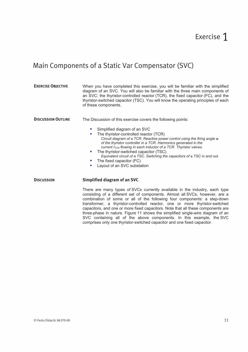
When you have completed this exercise, you will be familiar with the simplified diagram of an SVC. You will also be familiar with the three main components of an SVC: the thyristor-controlled reactor (TCR), the fixed capacitor (FC), and the thyristor-switched capacitor (TSC). You will know the operating principles of each of these components.
The Discussion of this exercise covers the following points:
Simplified diagram of an SVC
The thyristor-controlled reactor (TCR)Circuit diagram of a TCR. Reactive power control using the firing angle of the thyristor controller in a TCR. Harmonics generated in the current ITCR flowing in each inductor of a TCR. Thyristor valves.
The thyristor-switched capacitor (TSC)Equivalent circuit of a TSC. Switching the capacitors of a TSC in and out.
The fixed capacitor (FC)
Layout of an SVC substation
Simplified diagram of an SVC
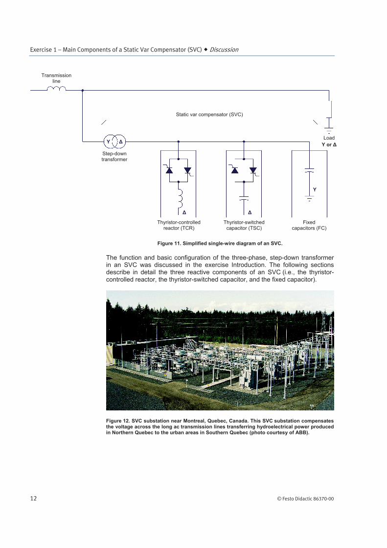
There are many types of SVCs currently available in the industry, each type consisting of a different set of components. Almost all SVCs, however, are a combination of some or all of the following four components: a step-down transformer, a thyristor-controlled reactor, one or more thyristor-switched capacitors, and one or more fixed capacitors. Note that all these components are three-phase in nature. Figure 11 shows the simplified single-wire diagram of an SVC containing all of the above components. In this example, the SVC comprises only one thyristor-switched capacitor and one fixed capacitor.
Main Components of a Static Var Compensator (SVC)
Exercise 1
EXERCISE OBJECTIVE
DISCUSSION OUTLINE
DISCUSSION
Exercise 1 – Main Components of a Static Var Compensator (SVC) Discussion
12 © Festo Didactic 86370-00
Figure 11. Simplified single-wire diagram of an SVC.
The function and basic configuration of the three-phase, step-down transformer in an SVC was discussed in the exercise Introduction. The following sections describe in detail the three reactive components of an SVC (i.e., the thyristor-controlled reactor, the thyristor-switched capacitor, and the fixed capacitor).
Figure 12. SVC substation near Montreal, Quebec, Canada. This SVC substation compensates the voltage across the long ac transmission lines transferring hydroelectrical power produced in Northern Quebec to the urban areas in Southern Quebec (photo courtesy of ABB).
Fixed capacitors (FC)
Thyristor-controlled reactor (TCR)
Thyristor-switched capacitor (TSC)
Y
Y or
Step-down transformer
Transmission line
Static var compensator (SVC)
Load Y
Exercise 1 – Main Components of a Static Var Compensator (SVC) Discussion
© Festo Didactic 86370-00 13
The thyristor-controlled reactor (TCR)
Circuit diagram of a TCR
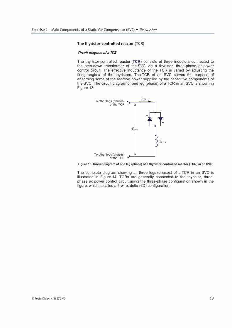
The thyristor-controlled reactor (TCR) consists of three inductors connected to the step-down transformer of the SVC via a thyristor, three-phase ac power control circuit. The effective inductance of the TCR is varied by adjusting the
firing angle of the thyristors. The TCR of an SVC serves the purpose of absorbing some of the reactive power supplied by the capacitive components of the SVC. The circuit diagram of one leg (phase) of a TCR in an SVC is shown in Figure 13.
Figure 13. Circuit diagram of one leg (phase) of a thyristor-controlled reactor (TCR) in an SVC.
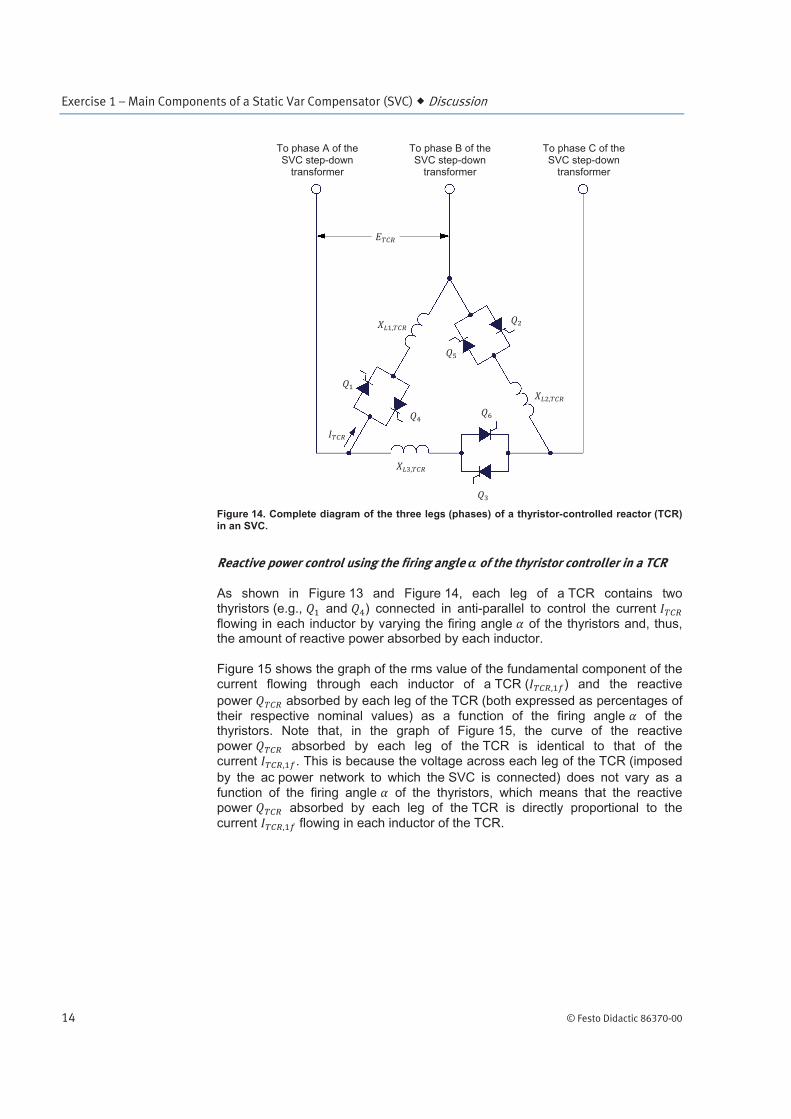
The complete diagram showing all three legs (phases) of a TCR in an SVC is illustrated in Figure 14. TCRs are generally connected to the thyristor, three-phase ac power control circuit using the three-phase configuration shown in the figure, which is called a 6-wire, delta (6D) configuration.
To other legs (phases)of the TCR
To other legs (phases)of the TCR
Exercise 1 – Main Components of a Static Var Compensator (SVC) Discussion
14 © Festo Didactic 86370-00
Figure 14. Complete diagram of the three legs (phases) of a thyristor-controlled reactor (TCR) in an SVC.
Reactive power control using the firing angle of the thyristor controller in a TCR
As shown in Figure 13 and Figure 14, each leg of a TCR contains two thyristors (e.g., and ) connected in anti-parallel to control the current
flowing in each inductor by varying the firing angle of the thyristors and, thus, the amount of reactive power absorbed by each inductor.
Figure 15 shows the graph of the rms value of the fundamental component of the current flowing through each inductor of a TCR ( ) and the reactive
power absorbed by each leg of the TCR (both expressed as percentages of
their respective nominal values) as a function of the firing angle of the thyristors. Note that, in the graph of Figure 15, the curve of the reactive
power absorbed by each leg of the TCR is identical to that of the current . This is because the voltage across each leg of the TCR (imposed
by the ac power network to which the SVC is connected) does not vary as a
function of the firing angle of the thyristors, which means that the reactive power absorbed by each leg of the TCR is directly proportional to the
current flowing in each inductor of the TCR.
To phase A of the SVC step-down
transformer
To phase C of the SVC step-down
transformer
To phase B of the SVC step-down
transformer
Exercise 1 – Main Components of a Static Var Compensator (SVC) Discussion
© Festo Didactic 86370-00 15
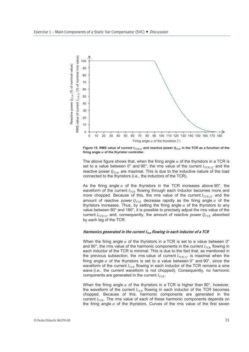
Figure 15. RMS value of current and reactive power in the TCR as a function of the
firing angle of the thyristor controller.
The above figure shows that, when the firing angle of the thyristors in a TCR is
set to a value between 0° and 90°, the rms value of the current and the
reactive power are maximal. This is due to the inductive nature of the load connected to the thyristors (i.e., the inductors of the TCR).
As the firing angle of the thyristors in the TCR increases above 90°, the waveform of the current flowing through each inductor becomes more and
more chopped. Because of this, the rms value of the current and the
amount of reactive power decrease rapidly as the firing angle of the thyristors increases. Thus, by setting the firing angle of the thyristors to any value between 90° and 180°, it is possible to precisely adjust the rms value of the
current and, consequently, the amount of reactive power absorbed
by each leg of the TCR.
Harmonics generated in the current ITCR flowing in each inductor of a TCR
When the firing angle of the thyristors in a TCR is set to a value between 0°
and 90°, the rms value of the harmonic components in the current flowing in each inductor of the TCR is minimal. This is due to the fact that, as mentioned in
the previous subsection, the rms value of current is maximal when the
firing angle of the thyristors is set to a value between 0° and 90°, since the waveform of the current flowing in each inductor of the TCR remains a sine wave (i.e., the current waveform is not chopped). Consequently, no harmonic components are generated in the current .
When the firing angle of the thyristors in a TCR is higher than 90°, however, the waveform of the current flowing in each inductor of the TCR becomes chopped. Because of this, harmonic components are generated in the
current . The rms value of each of these harmonic components depends on the firing angle of the thyristors. Curves of the rms value of the first seven
Re
active
po
we
r (
% o
f n
om
ina
l va
lue
)
Firing angle of the thyristors (°)
RM
S v
alu
e o
f cu
rre
nt
(%
of
no
min
al rm
s v
alu
e)
0 10 20 30 40 50 60 70 80 90 100 110 120 130 140 150 160 170 1800
10
20
30
40
50
60
70
80
90
100
Exercise 1 – Main Components of a Static Var Compensator (SVC) Discussion
16 © Festo Didactic 86370-00
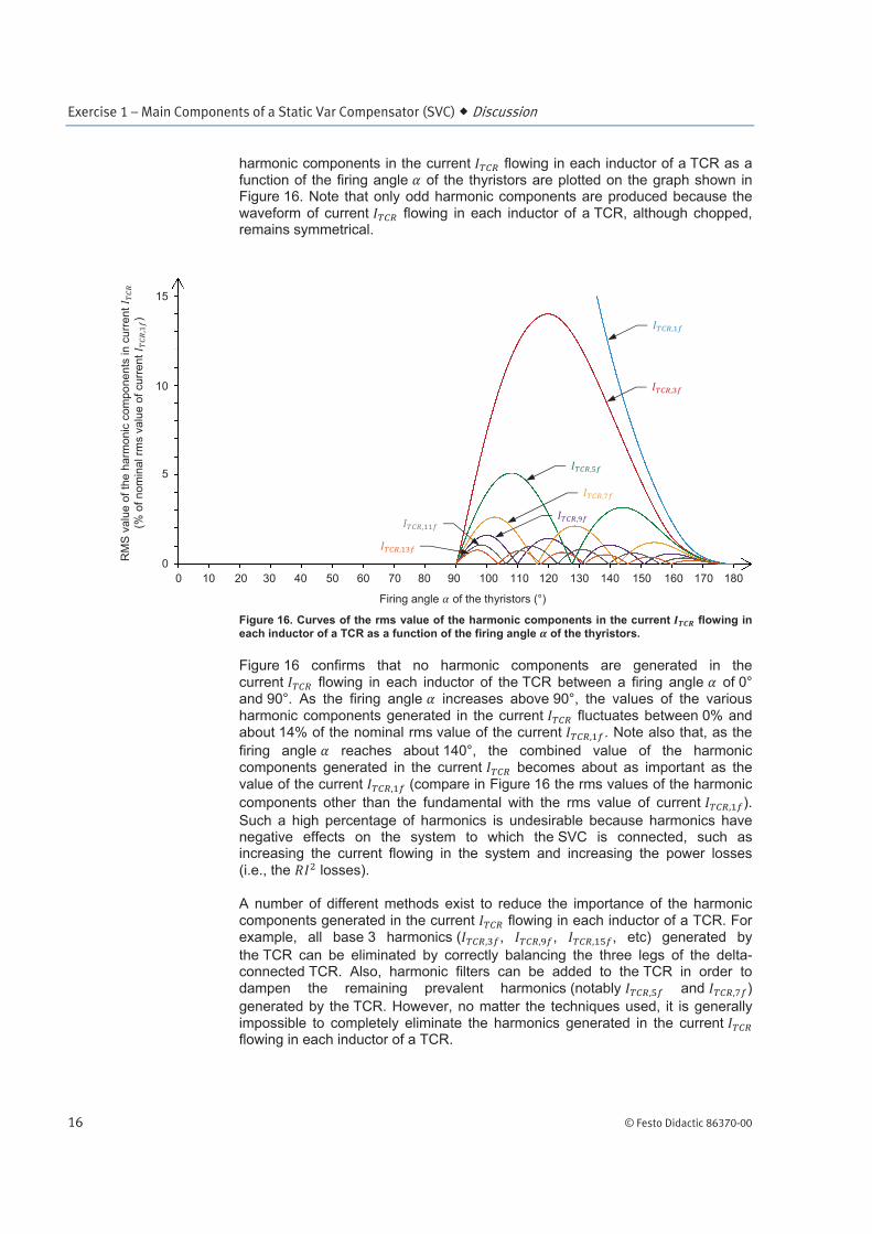
harmonic components in the current flowing in each inductor of a TCR as a function of the firing angle of the thyristors are plotted on the graph shown in Figure 16. Note that only odd harmonic components are produced because the waveform of current flowing in each inductor of a TCR, although chopped, remains symmetrical.
Figure 16. Curves of the rms value of the harmonic components in the current flowing in
each inductor of a TCR as a function of the firing angle of the thyristors.
Figure 16 confirms that no harmonic components are generated in the
current flowing in each inductor of the TCR between a firing angle of 0° and 90°. As the firing angle increases above 90°, the values of the various
harmonic components generated in the current fluctuates between 0% and about 14% of the nominal rms value of the current . Note also that, as the
firing angle reaches about 140°, the combined value of the harmonic components generated in the current becomes about as important as the
value of the current (compare in Figure 16 the rms values of the harmonic
components other than the fundamental with the rms value of current ).
Such a high percentage of harmonics is undesirable because harmonics have negative effects on the system to which the SVC is connected, such as increasing the current flowing in the system and increasing the power losses
(i.e., the losses).
A number of different methods exist to reduce the importance of the harmonic
components generated in the current flowing in each inductor of a TCR. For example, all base 3 harmonics ( , , , etc) generated by
the TCR can be eliminated by correctly balancing the three legs of the delta-connected TCR. Also, harmonic filters can be added to the TCR in order to dampen the remaining prevalent harmonics (notably and )
generated by the TCR. However, no matter the techniques used, it is generally impossible to completely eliminate the harmonics generated in the current flowing in each inductor of a TCR.
RM
S v
alu
e o
f th
e h
arm
on
ic c
om
po
ne
nts
in
cu
rre
nt
(% o
f n
om
ina
l rm
s v
alu
e o
f cu
rre
nt
)
Firing angle of the thyristors (°)
0
5
10
10 20 30 40 50 60 70 80 90 100 110 120 130 140 150 160 170 180
0
15
Exercise 1 – Main Components of a Static Var Compensator (SVC) Discussion
© Festo Didactic 86370-00 17
Thyristor valves
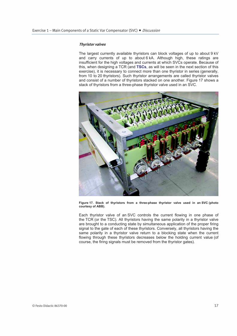
The largest currently available thyristors can block voltages of up to about 9 kV and carry currents of up to about 6 kA. Although high, these ratings are insufficient for the high voltages and currents at which SVCs operate. Because of this, when designing a TCR (and TSCs, as will be seen in the next section of this exercise), it is necessary to connect more than one thyristor in series (generally, from 10 to 20 thyristors). Such thyristor arrangements are called thyristor valves and consist of a number of thyristors stacked on one another. Figure 17 shows a stack of thyristors from a three-phase thyristor valve used in an SVC.
Figure 17. Stack of thyristors from a three-phase thyristor valve used in an SVC (photo courtesy of ABB).
Each thyristor valve of an SVC controls the current flowing in one phase of the TCR (or the TSC). All thyristors having the same polarity in a thyristor valve are brought to a conducting state by simultaneous application of the proper firing signal to the gate of each of these thyristors. Conversely, all thyristors having the same polarity in a thyristor valve return to a blocking state when the current flowing through these thyristors decreases below the holding current value (of course, the firing signals must be removed from the thyristor gates).
Exercise 1 – Main Components of a Static Var Compensator (SVC) Discussion
18 © Festo Didactic 86370-00
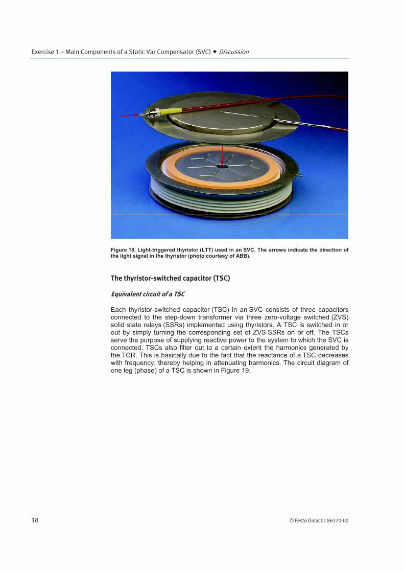
Figure 18. Light-triggered thyristor (LTT) used in an SVC. The arrows indicate the direction of the light signal in the thyristor (photo courtesy of ABB).
The thyristor-switched capacitor (TSC)
Equivalent circuit of a TSC
Each thyristor-switched capacitor (TSC) in an SVC consists of three capacitors connected to the step-down transformer via three zero-voltage switched (ZVS) solid state relays (SSRs) implemented using thyristors. A TSC is switched in or out by simply turning the corresponding set of ZVS SSRs on or off. The TSCs serve the purpose of supplying reactive power to the system to which the SVC is connected. TSCs also filter out to a certain extent the harmonics generated by the TCR. This is basically due to the fact that the reactance of a TSC decreases with frequency, thereby helping in attenuating harmonics. The circuit diagram of one leg (phase) of a TSC is shown in Figure 19.
Exercise 1 – Main Components of a Static Var Compensator (SVC) Discussion
© Festo Didactic 86370-00 19
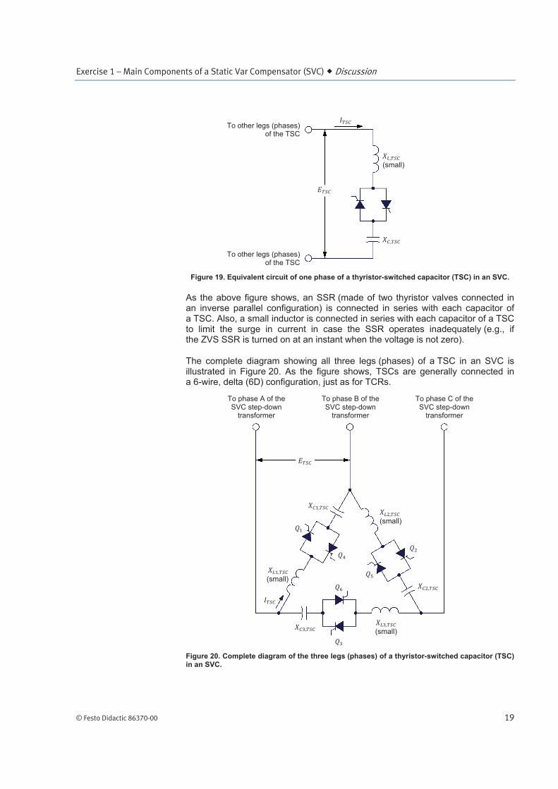
Figure 19. Equivalent circuit of one phase of a thyristor-switched capacitor (TSC) in an SVC.
As the above figure shows, an SSR (made of two thyristor valves connected in an inverse parallel configuration) is connected in series with each capacitor of a TSC. Also, a small inductor is connected in series with each capacitor of a TSC to limit the surge in current in case the SSR operates inadequately (e.g., if the ZVS SSR is turned on at an instant when the voltage is not zero).
The complete diagram showing all three legs (phases) of a TSC in an SVC is illustrated in Figure 20. As the figure shows, TSCs are generally connected in a 6-wire, delta (6D) configuration, just as for TCRs.
Figure 20. Complete diagram of the three legs (phases) of a thyristor-switched capacitor (TSC) in an SVC.
(small)
(small)
(small)
(small)
To phase A of the SVC step-down
transformer
To phase C of the SVC step-down
transformer
To phase B of the SVC step-down
transformer
To other legs (phases)of the TSC
To other legs (phases)of the TSC
Exercise 1 – Main Components of a Static Var Compensator (SVC) Discussion
20 © Festo Didactic 86370-00
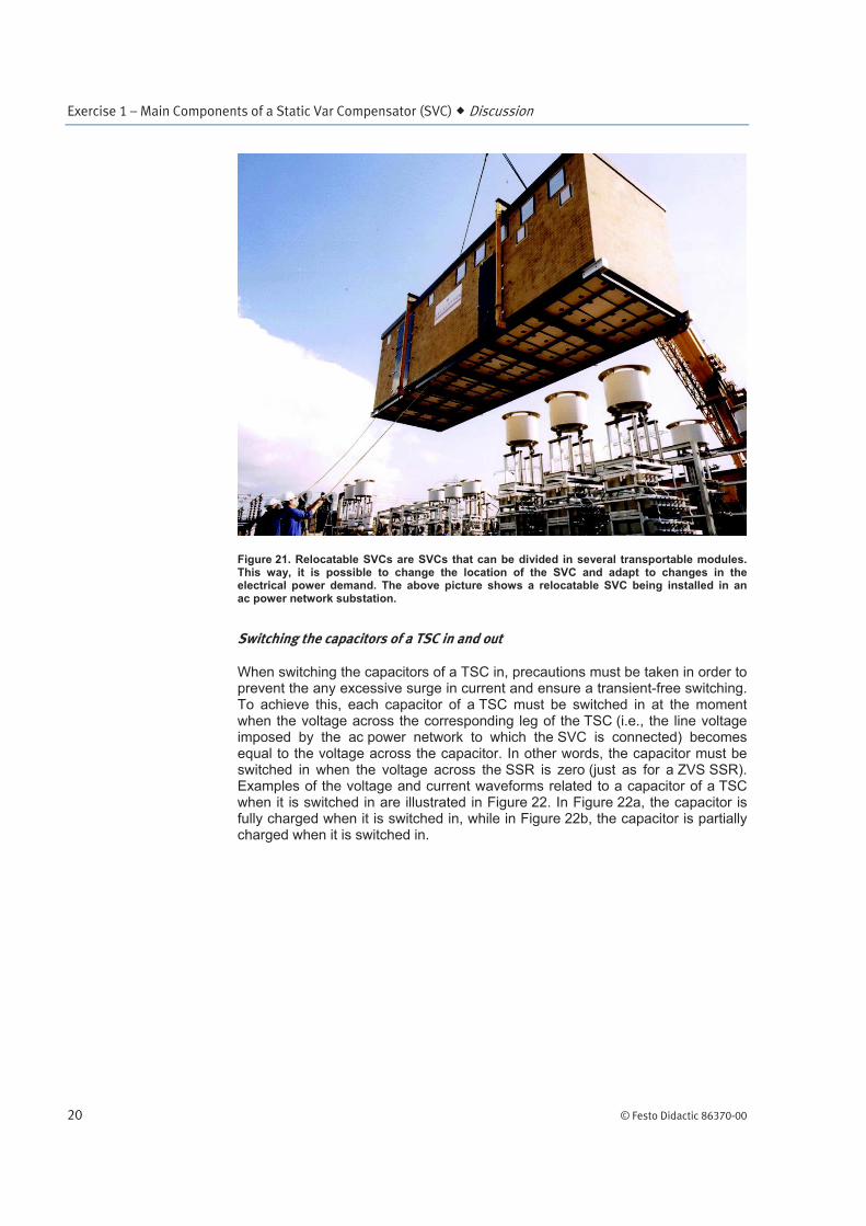
Figure 21. Relocatable SVCs are SVCs that can be divided in several transportable modules. This way, it is possible to change the location of the SVC and adapt to changes in the electrical power demand. The above picture shows a relocatable SVC being installed in an ac power network substation.
Switching the capacitors of a TSC in and out
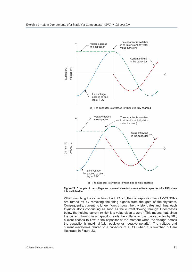
When switching the capacitors of a TSC in, precautions must be taken in order to prevent the any excessive surge in current and ensure a transient-free switching. To achieve this, each capacitor of a TSC must be switched in at the moment when the voltage across the corresponding leg of the TSC (i.e., the line voltage imposed by the ac power network to which the SVC is connected) becomes equal to the voltage across the capacitor. In other words, the capacitor must be switched in when the voltage across the SSR is zero (just as for a ZVS SSR). Examples of the voltage and current waveforms related to a capacitor of a TSC when it is switched in are illustrated in Figure 22. In Figure 22a, the capacitor is fully charged when it is switched in, while in Figure 22b, the capacitor is partially charged when it is switched in.
Exercise 1 – Main Components of a Static Var Compensator (SVC) Discussion
© Festo Didactic 86370-00 21
Figure 22. Example of the voltage and current waveforms related to a capacitor of a TSC when it is switched in.
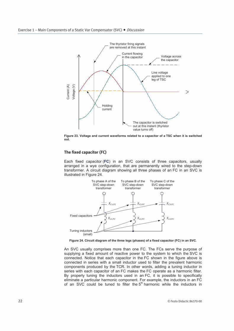
When switching the capacitors of a TSC out, the corresponding set of ZVS SSRs are turned off by removing the firing signals from the gate of the thyristors. Consequently, current no longer flows through the thyristor gates and, thus, each thyristor stops conducting as soon as the current flowing through it decreases below the holding current (which is a value close to zero). This means that, since the current flowing in a capacitor leads the voltage across the capacitor by 90°, current ceases to flow in the capacitor at the moment when the voltage across the capacitor is maximal (with positive or negative polarity). The voltage and current waveforms related to a capacitor of a TSC when it is switched out are illustrated in Figure 23.
(b) The capacitor is switched in when it is partially charged
(a) The capacitor is switched in when it is fully charged
Vo
lta
ge
(V
)
Curr
ent (A
)
The capacitor is switched in at this instant (thyristor value turns on)
Current flowingin the capacitor
Voltage across the capacitor
Vo
lta
ge
(V
)
Curr
ent (A
)
Line voltage applied to one leg of TSC
Current flowingin the capacitor
Voltage across the capacitor
Line voltage applied to one leg of TSC
The capacitor is switched in at this instant (thyristor value turns on)
Exercise 1 – Main Components of a Static Var Compensator (SVC) Discussion
22 © Festo Didactic 86370-00
Figure 23. Voltage and current waveforms related to a capacitor of a TSC when it is switched out.
The fixed capacitor (FC)
Each fixed capacitor (FC) in an SVC consists of three capacitors, usually arranged in a wye configuration, that are permanently wired to the step-down transformer. A circuit diagram showing all three phases of an FC in an SVC is illustrated in Figure 24.
Figure 24. Circuit diagram of the three legs (phases) of a fixed capacitor (FC) in an SVC.
An SVC usually comprises more than one FC. The FCs serve the purpose of supplying a fixed amount of reactive power to the system to which the SVC is connected. Notice that each capacitor in the FC shown in the figure above is connected in series with a small inductor used to filter the prevalent harmonic components produced by the TCR. In other words, adding a tuning inductor in series with each capacitor of an FC makes the FC operate as a harmonic filter. By properly tuning the inductors used in an FC, it is possible to specifically eliminate a particular harmonic component. For example, the inductors in an FC of an SVC could be tuned to filter the 5
th harmonic while the inductors in
Vo
lta
ge
(V
)
Curr
ent (A
)
Voltage across the capacitor
The capacitor is switched out at this instant (thyristor value turns off)
Holding current
The thyristor firing signals are removed at this instant
Current flowing in the capacitor
Tuning inductors(small)
Fixed capacitors
Line voltage applied to one leg of TSC
To phase A of the SVC step-down
transformer
To phase C of the SVC step-down
transformer
To phase B of the SVC step-down
transformer
Exercise 1 – Main Components of a Static Var Compensator (SVC) Discussion
© Festo Didactic 86370-00 23
another FC of the SVC could be tuned to filter the 7th harmonic. The principles
behind the tuning of the inductors used in the FCs in order to filter harmonic components are beyond the scope of this manual.
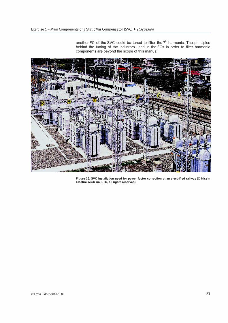
Figure 25. SVC installation used for power factor correction at an electrified railway (© Nissin Electric WuXi Co.,LTD, all rights reserved).
Exercise 1 – Main Components of a Static Var Compensator (SVC) Discussion
24 © Festo Didactic 86370-00
Layout of an SVC substation
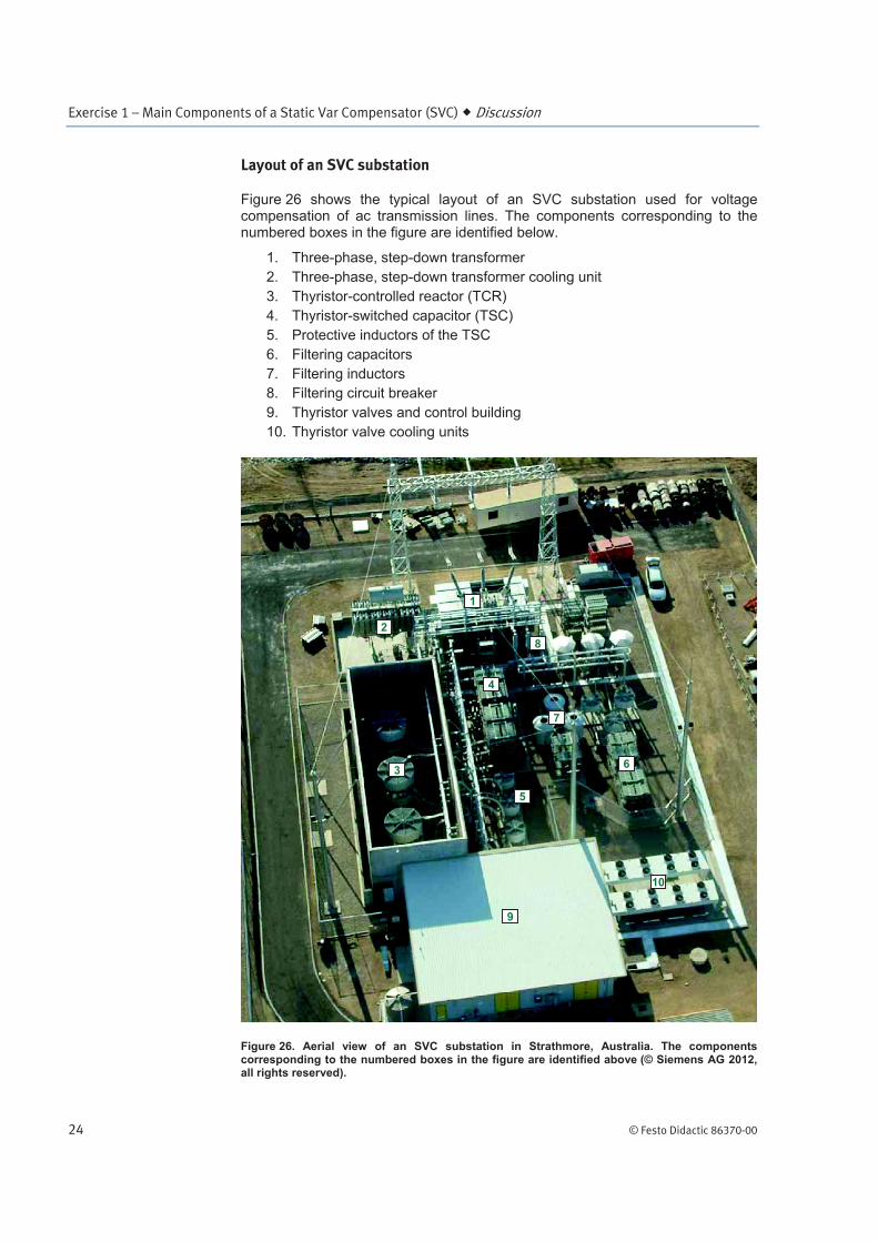
Figure 26 shows the typical layout of an SVC substation used for voltage compensation of ac transmission lines. The components corresponding to the numbered boxes in the figure are identified below.
1. Three-phase, step-down transformer
2. Three-phase, step-down transformer cooling unit
3. Thyristor-controlled reactor (TCR)
4. Thyristor-switched capacitor (TSC)
5. Protective inductors of the TSC
6. Filtering capacitors
7. Filtering inductors
8. Filtering circuit breaker
9. Thyristor valves and control building
10. Thyristor valve cooling units
Figure 26. Aerial view of an SVC substation in Strathmore, Australia. The components corresponding to the numbered boxes in the figure are identified above (© Siemens AG 2012, all rights reserved).
3
9
2
4
5
7
6
10
8
1
Exercise 1 – Main Components of a Static Var Compensator (SVC) Procedure Outline
© Festo Didactic 86370-00 25
The Procedure is divided into the following sections:
Set up and connections
TCR operation
TSC operation
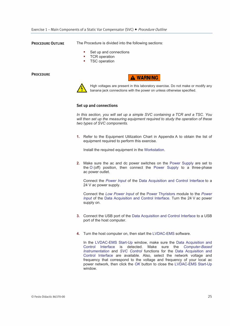
High voltages are present in this laboratory exercise. Do not make or modify any
banana jack connections with the power on unless otherwise specified.
Set up and connections
In this section, you will set up a simple SVC containing a TCR and a TSC. You will then set up the measuring equipment required to study the operation of these two types of SVC components.
1. Refer to the Equipment Utilization Chart in Appendix A to obtain the list of equipment required to perform this exercise.
Install the required equipment in the Workstation.
2. Make sure the ac and dc power switches on the Power Supply are set to the O (off) position, then connect the Power Supply to a three-phase ac power outlet.
Connect the Power Input of the Data Acquisition and Control Interface to a 24 V ac power supply.
Connect the Low Power Input of the Power Thyristors module to the Power Input of the Data Acquisition and Control Interface. Turn the 24 V ac power supply on.
3. Connect the USB port of the Data Acquisition and Control Interface to a USB port of the host computer.
4. Turn the host computer on, then start the LVDAC-EMS software.
In the LVDAC-EMS Start-Up window, make sure the Data Acquisition and Control Interface is detected. Make sure the Computer-Based Instrumentation and SVC Control functions for the Data Acquisition and Control Interface are available. Also, select the network voltage and frequency that correspond to the voltage and frequency of your local ac power network, then click the OK button to close the LVDAC-EMS Start-Up window.
PROCEDURE OUTLINE
PROCEDURE
Exercise 1 – Main Components of a Static Var Compensator (SVC) Procedure
26 © Festo Didactic 86370-00
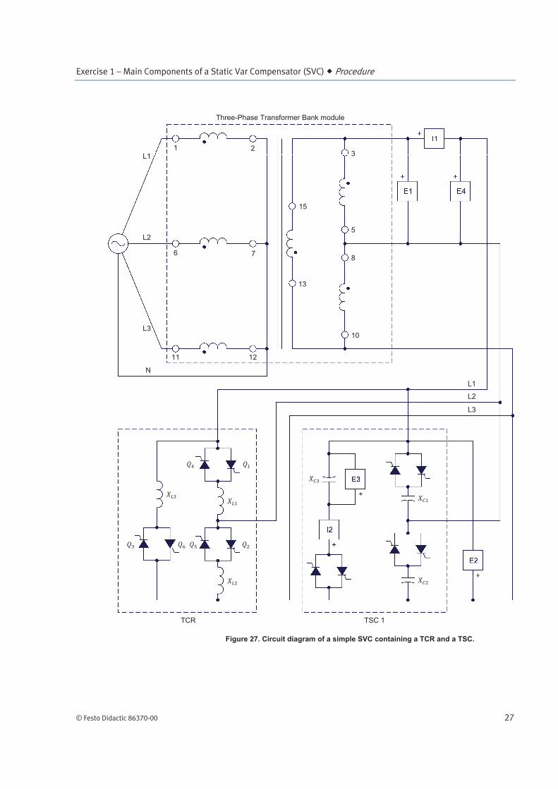
5. Connect the equipment as shown in Figure 27. Use the reactors and thyristor switched capacitor 1 (TSC 1) in the SVC Reactors/Thyristor Switched Capacitors module to implement the TCR and the TSC, respectively, shown in Figure 27. Also, use the Power Thyristors module to implement the TCR.
Before connecting the TCR, make sure that switch S1 on the Power Thyristors module is set to the O (open) position, then set switch S2 to
the I (closed) position. Doing so connects thyristor in series with thyristor , thyristor in series with thyristor , and thyristor in series
with thyristor . This reduces the number of leads required to connect the TCR.
Also, note that, in the circuit of Figure 27, the inputs used to measure the reactive power which the SVC exchanges with the ac power source (i.e., the network) and the magnitude of the harmonic components in the line currents due to the operation of the TCR and TSC of the SVC (i.e., inputs E1 and I1) are connected at the secondary windings of the three-phase, step-down transformer, instead of directly to the ac power network. This ensures that the reactive power and the magnitude of the harmonic components in the line current that are measured are produced by the TCR and the TSC in the SVC exclusively, and not by the three-phase, step-down transformer (which absorbs a small amount of reactive power and also produces harmonics in the line current).
Exercise 1 – Main Components of a Static Var Compensator (SVC) Procedure
© Festo Didactic 86370-00 27
Figure 27. Circuit diagram of a simple SVC containing a TCR and a TSC.
TCR
Three-Phase Transformer Bank module
TSC 1
1 2
6 7
11 12
15
13
3
5
8
10
L1
L2
L3
N
L1
L2
L3
Exercise 1 – Main Components of a Static Var Compensator (SVC) Procedure
28 © Festo Didactic 86370-00
a In the circuit of Figure 27, input E4 of the Data Acquisition and Control Interface is used for synchronization of the firing signals of the thyristors in the Power Thyristors module. Because of this, input E4 cannot be used for voltage measurement using the LVDAC-EMS instrumentation.
6. Connect the Digital Outputs of the Data Acquisition and Control Interface to the Firing Control Inputs of the Power Thyristors module using the provided cable with DB9 connectors. This connection conveys the firing signals to the thyristors in the Power Thyristors module. These firing control signals are provided by the Data Acquisition and Control Interface and controlled in the SVC Control window of the LVDAC-EMS software.
Also, connect Digital Output 1 of the Data Acquisition and Control Interface to the TSC 1 Switching Control Input on the SVC Reactors/Thyristor Switched Capacitors module using a miniature banana plug lead. Connect a digital (D) common terminal (white) of the Digital Outputs on the Data Acquisition and Control Interface to the common terminal of the TSC Switching Control Inputs on the SVC Reactors/Thyristor Switched Capacitors module using a miniature banana plug lead. These connections provide the switching signal that controls TSC 1 in the SVC Reactors/Thyristor Switched Capacitors module. This switching signal is provided by the Data Acquisition and Control Interface and controlled in the SVC Control window of the LVDAC-EMS software.
7. In LVDAC-EMS, open the SVC Control window and make the following settings:
Make sure the Function parameter is set to Static Var Compensator. This function is required to allow control of the firing angle of the thyristors in the TCR, as well as to switch the TSCs in and out.
Set the Control Mode parameter to Manual Control. This allows manual control of the firing angle of the thyristors in the TCR and enables manual switching of the TSCs.
Set the TCR Firing Angle parameter to 0° by entering 0 in the field next to this parameter or by using the control knob in the lower left corner of the window. This sets the firing angle of the TCR to 0°.
Make sure the TSC 1 parameter is set to Switched Out. This ensures that TSC 1 is switched out and, thus, that it does not supply any reactive power.
Start the Static Var Compensator function by clicking the Start/Stop button or by setting the Status parameter to Started.
8. In LVDAC-EMS, open the Metering window. Once in the Metering window, open the Acquisition Settings dialog box. Set the Sampling Window to 8 cycles then click OK to close the dialog box. This is necessary to be able to measure the magnitude of the harmonic components produced by the SVC.
Exercise 1 – Main Components of a Static Var Compensator (SVC) Procedure
© Festo Didactic 86370-00 29
In the Metering window, set three meters to measure the rms values (ac) of
the fundamental component and harmonic components in the current flowing in the SVC (input I1). Set one of these meters to measure the
fundamental component of the current by right-clicking the AC button, then selecting AC 1. Set the two other meters to measure the 5
th and 7
th
harmonic components of the current by right-clicking the AC button on each of these meter, then selecting AC 5 and AC 7. Finally, set a meter to
measure the three-phase reactive power in the SVC [metering function PQS1 (E1, I1) 3~].
TCR operation
In this section, you will increase the firing angle of the thyristors in the TCR from 0° to 180°. As you do so, you will observe what happens to the fundamental component (both the rms value and the waveform) of the current flowing in the TCR and the reactive power in the TCR. You will also measure the amount of reactive power absorbed by the TCR, and confirm that it is as expected. You will then repeat the process and, as you do so, observe in the Harmonic Analyzer what happens to the harmonic content of the current flowing in the TCR. Finally, you will again repeat the process, this time recording in the Data Table the rms values of the fundamental component, 5
th harmonic component,
and 7th harmonic component of the current flowing in the TCR, as well as the
reactive power in the TCR. You will then analyze the results.
9. Turn the three-phase ac power source in the Power Supply on.
10. In the SVC Control window, slowly increase by steps the TCR Firing Angle parameter to 90°. While doing so, observe in the Metering window the values
of the fundamental component of the current flowing in the SVC as well as the reactive power in the SVC.
a Since the TSC of the SVC is switched out, the current flowing in the SVC corresponds to the current flowing in the TCR. Also, the reactive power corresponds to the reactive power in the TCR.
Are the values of the fundamental component of the current and the reactive power virtually constant as the TCR firing angle is varied from 0° to 90°?
Yes No
a The fundamental component of the current (and, consequently, the reactive power ) begins to decrease when the TCR firing angle is increased above a value of about 85°, instead of 90° as stated in the theory. This is due to the fact that the inductors in the TCR are not ideal and have a certain resistance value.
Does this confirm the theory presented in this exercise discussion?
Yes No
Exercise 1 – Main Components of a Static Var Compensator (SVC) Procedure
30 © Festo Didactic 86370-00
11. In the SVC Control window, set the TCR Firing Angle parameter to 0° so that
the rms value of the fundamental component of the current is maximal.
In the Metering window, measure the nominal value of the fundamental
component of the current flowing in the TCR ( ) and the
reactive power in the TCR (i.e., the maximal values obtained when
the thyristors of the TCR are set to a full-conducting state). Record the values below.
Current A
Reactive power var
12. Observe the front panel of the SVC Reactors/ Thyristor Switched Capacitors module. Note below the reactive power rating of each reactor in the TCR.
TCR reactive power rating (each reactor) var
Is the amount of reactive power in the TCR you measured in the
previous step approximately equal to three times the reactive power rating of each reactor you just recorded?
Yes No
13. In the SVC Control window, set the TCR Firing Angle parameter to 90°.
In LVDAC-EMS, open the Oscilloscope, and display the waveform of the current flowing in the SVC (i.e., the waveform of the current flowing in the TCR).
In the SVC Control window, slowly increase the TCR Firing Angle parameter to 180°. While doing so, observe on the Oscilloscope what happens to the
waveform of the current flowing in the TCR. Also, observe in the Metering window what happens to the values of the fundamental component
of the current and the reactive power in the TCR.
What happens to the amplitude of the waveform of the current flowing in the TCR as you increase the TCR firing angle to 180°?
Exercise 1 – Main Components of a Static Var Compensator (SVC) Procedure
© Festo Didactic 86370-00 31
What happens to the values of the fundamental component of the
current and the reactive power in the TCR as you increase the TCR firing angle to 180°?
14. Considering your answers to the questions in the previous step, determine
the relationship between the fundamental component of the current flowing in the TCR, as well as the amount of reactive power in the TCR, and the TCR firing angle. Explain briefly.
15. In LVDAC-EMS, open the Harmonic Analyzer. Make sure the fundamental frequency is set to the frequency of your local ac power network, then set the number of harmonics displayed to 10. Display the harmonic content of the
current (input I1) flowing in the SVC (i.e., the harmonic content of the current flowing in the TCR). Finally, select the relative vertical scale graduated with respect to the value of the fundamental frequency component (% of 1f).
16. In the SVC Control window, set the TCR Firing Angle parameter to 0°, then slowly increase the parameter to 180°. While doing so, observe the
magnitude of the harmonic components in the current (expressed as a percentage of the fundamental component).
What happens to the magnitude of the harmonic components in the
current as you increase the TCR firing angle from 0° to 180°? Explain briefly.
Exercise 1 – Main Components of a Static Var Compensator (SVC) Procedure
32 © Festo Didactic 86370-00
Do your results confirm the theory presented in this exercise discussion?
Yes No
Close the Harmonic Analyzer.
17. In the SVC Control window, set the TCR Firing Angle parameter to 0°.
18. In LVDAC-EMS, open the Data Table window.
Set the Data Table to record the rms values of the fundamental component, 5
th harmonic component, and 7
th harmonic component of the current , as
well as the reactive power in the TCR indicated in the Metering window.
Also, set the Data Table to record the TCR firing angle indicated in the SVC Control window.
In the Data Table window, click on the Record Data button to record the values of the fundamental component, 5
th harmonic component, and 7
th
harmonic component of the current , the reactive power , and the TCR firing angle.
19. In the SVC Control window, increase the TCR firing angle to 180° by steps of 5°. For each value of the TCR firing angle, record the parameters in the Data Table.
20. In the Data Table window, save the recorded data, then export it to a spreadsheet application.
In the spreadsheet application, add three new columns for the following parameters: the fundamental component, 5
th harmonic component,
and 7th harmonic component of the current flowing in the TCR,
expressed as percentages of the nominal current . To calculate
these new parameters, divide the rms values of the fundamental component, 5
th harmonic component, and 7
th harmonic component of the current by
the rms value of the nominal current you recorded in step 11,
then multiply the results by 100 to obtain percentage values.
21. Using the recorded data, plot a graph of the fundamental component of the current flowing in the TCR, expressed as a percentage of the nominal
current , as a function of the TCR firing angle.
Plot also a graph of the reactive power in the TCR as a function of the TCR firing angle.
Exercise 1 – Main Components of a Static Var Compensator (SVC) Procedure
© Festo Didactic 86370-00 33
Observe the graphs. What happens to the fundamental component of the
current and to the reactive power as the TCR firing angle increases? Explain briefly.
22. Using the recorded values, plot a graph of the 5th and 7
th harmonic
components of the current flowing in the TCR, expressed as
percentages of the nominal current , as a function of the
TCR firing angle.
Observe the graph. What happens to the magnitude of the 5th
and 7th harmonic components of the current as the TCR firing angle
increases? Explain briefly.
Do your results confirm the theory presented in this exercise discussion?
Yes No
Exercise 1 – Main Components of a Static Var Compensator (SVC) Procedure
34 © Festo Didactic 86370-00
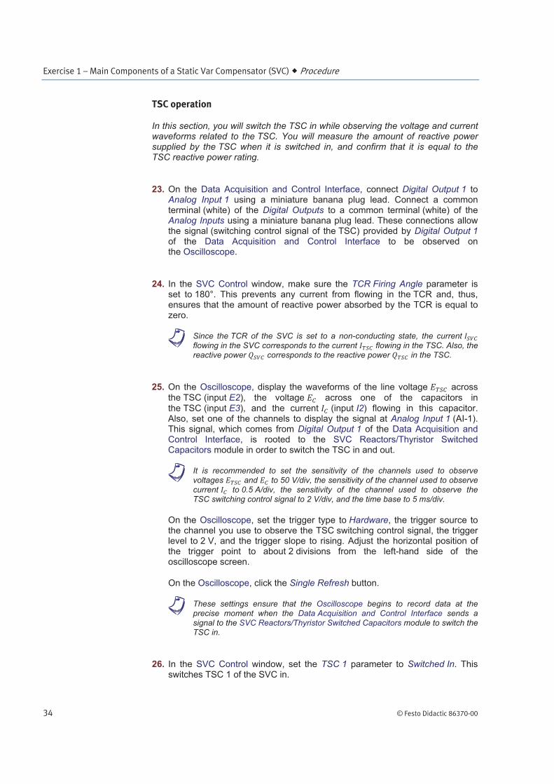
TSC operation
In this section, you will switch the TSC in while observing the voltage and current waveforms related to the TSC. You will measure the amount of reactive power supplied by the TSC when it is switched in, and confirm that it is equal to the TSC reactive power rating.
23. On the Data Acquisition and Control Interface, connect Digital Output 1 to Analog Input 1 using a miniature banana plug lead. Connect a common terminal (white) of the Digital Outputs to a common terminal (white) of the Analog Inputs using a miniature banana plug lead. These connections allow the signal (switching control signal of the TSC) provided by Digital Output 1 of the Data Acquisition and Control Interface to be observed on the Oscilloscope.
24. In the SVC Control window, make sure the TCR Firing Angle parameter is set to 180°. This prevents any current from flowing in the TCR and, thus, ensures that the amount of reactive power absorbed by the TCR is equal to zero.
a Since the TCR of the SVC is set to a non-conducting state, the current flowing in the SVC corresponds to the current flowing in the TSC. Also, the reactive power corresponds to the reactive power in the TSC.
25. On the Oscilloscope, display the waveforms of the line voltage across
the TSC (input E2), the voltage across one of the capacitors in the TSC (input E3), and the current (input I2) flowing in this capacitor. Also, set one of the channels to display the signal at Analog Input 1 (AI-1). This signal, which comes from Digital Output 1 of the Data Acquisition and Control Interface, is rooted to the SVC Reactors/Thyristor Switched Capacitors module in order to switch the TSC in and out.
a It is recommended to set the sensitivity of the channels used to observe voltages and to 50 V/div, the sensitivity of the channel used to observe current to 0.5 A/div, the sensitivity of the channel used to observe the TSC switching control signal to 2 V/div, and the time base to 5 ms/div.
On the Oscilloscope, set the trigger type to Hardware, the trigger source to the channel you use to observe the TSC switching control signal, the trigger level to 2 V, and the trigger slope to rising. Adjust the horizontal position of the trigger point to about 2 divisions from the left-hand side of the oscilloscope screen.
On the Oscilloscope, click the Single Refresh button.
a These settings ensure that the Oscilloscope begins to record data at the precise moment when the Data Acquisition and Control Interface sends a signal to the SVC Reactors/Thyristor Switched Capacitors module to switch the TSC in.
26. In the SVC Control window, set the TSC 1 parameter to Switched In. This switches TSC 1 of the SVC in.
Exercise 1 – Main Components of a Static Var Compensator (SVC) Conclusion
© Festo Didactic 86370-00 35
On the Oscilloscope, observe the voltage and current waveforms measured when the TSC is switched in.
Describe what happens when the TSC is switched in. Explain briefly.
27. In the Metering window, observe the fundamental component of the current flowing in the TSC and the amount of reactive power in the TSC when the TSC is switched in. Record the values below.
Current A
Reactive power var
28. Observe the front panel of the SVC Reactors/Thyristor Switched Capacitors module. Note below the reactive power rating of each capacitor in the TSC.
TSC reactive power rating (each capacitor) var
Is the amount of reactive power in the TSC you measured in the previous step approximately equal to three times (neglect the polarity) the reactive power rating of each capacitor you just recorded?
Yes No
29. In the SVC Control window, stop the Static Var Compensator function by clicking the Start/Stop button or by setting the Status parameter to Stopped.
30. Turn the three-phase ac power source in the Power Supply off.
31. Close LVDAC-EMS. Disconnect all leads and return them to their storage location.
In this exercise, you familiarized yourself with the simplified diagram of an SVC. You also familiarized yourself with the three main components of an SVC: the thyristor-controlled reactor (TCR), the thyristor-switched capacitor (TSC), and the fixed capacitor (FC). You learned the operating principles of each of these components.
CONCLUSION
Exercise 1 – Main Components of a Static Var Compensator (SVC) Review Questions
36 © Festo Didactic 86370-00
1. What are the two primary advantages of SVCs over shunt-capacitor substations when they are used for voltage compensation of ac transmission lines?
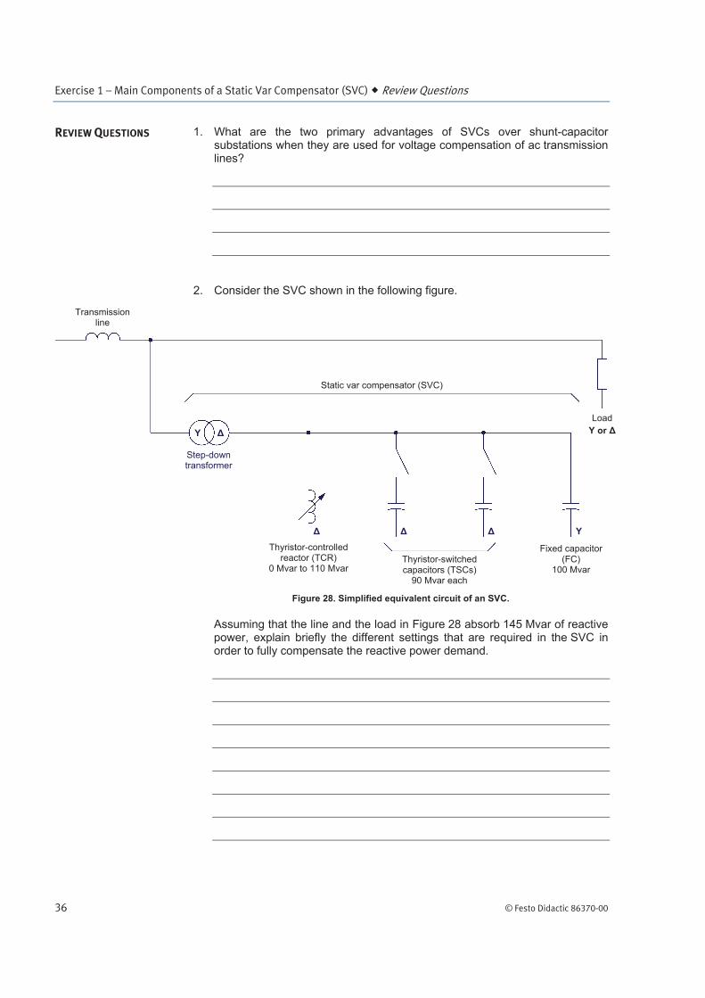
2. Consider the SVC shown in the following figure.
Figure 28. Simplified equivalent circuit of an SVC.
Assuming that the line and the load in Figure 28 absorb 145 Mvar of reactive power, explain briefly the different settings that are required in the SVC in order to fully compensate the reactive power demand.
REVIEW QUESTIONS
Static var compensator (SVC)
Step-down transformer
Transmission line
Thyristor-controlled reactor (TCR)
0 Mvar to 110 MvarThyristor-switched capacitors (TSCs)
90 Mvar each
Fixed capacitor (FC)
100 Mvar
Y
Y or
Load
Y
Exercise 1 – Main Components of a Static Var Compensator (SVC) Review Questions
© Festo Didactic 86370-00 37
3. Briefly explain how the amount of reactive power absorbed by each inductor of a TCR can be adjusted.
4. What are the two primary uses of FCs in an SVC?
5. Briefly explain the correct procedure for switching each capacitor of a TSC in.