Embed Size (px)
Citation preview

NASATechnical
Paper2973
1990
National Aeronautics andSpace Administration
Office of Management
Scientific and TechnicalInformation Division
Static Investigationof a Two-Dimensional
Convergent-DivergentExhaust Nozzle WithMultiaxis Thrust-
Vectoring Capability
John G. Taylor
Langley Research Center
Hampton, Virginia
https://ntrs.nasa.gov/search.jsp?R=19900009877 2018-05-30T01:46:34+00:00Z


Summary
An investigation was conducted in the static
test facility of the Langley 16-Foot Transonic Tun-nel to determine the internal performance of two-
dimensional convergent-divergent nozzles designed to
have simultaneous pitch and yaw thrust-vectoring ca-
pability. This concept utilized divergent flap rotation
for thrust vectoring in the pitch plane and deflection
of flat yaw flaps hinged at the end of the sidewalls
for yaw thrust vectoring. The hinge location of the
yaw flaps was varied at four positions from the nozzleexit plane to the throat plane. The yaw flaps were
designed to contain the flow laterally independent of
power setting. In order to eliminate any physical
interference between the yaw flap deflected into the
exhaust stream and the divergent flaps, the down-
stream corners of both upper and lower divergent
flaps were cut off to allow for up to 30 ° of yaw-flap
deflection. This investigation studied tile impact of
varying the nozzle pitch vector angle, throat area,
yaw-flap hinge location, yaw-flap length, and yaw-
flap deflection angle on nozzle internal performance
characteristics. High-pressure air was used to sim-
ulate the jet exhaust at nozzle pressure ratios upto 7.0.
Static results indicated that configurations with
the yaw-flap hinge located upstream of the exit planeprovided relatively high levels of thrust-vectoring
efficiency without causing large losses in resultantthrust ratio. Therefore, these configurations rep-
resent a viable concept for providing simultaneous
pitch and yaw thrust vectoring.
Introduction
Mission requirements for the next-generation
fighter will probably require fl_ture combat aircraft
to have short takeoff and landing characteristics in
order to operate from bomb-danlaged runways andto be able to cruise at supersonic speeds. These fu-
ture aircraft will probably also possess an increased
level of maneuverability at transonic and supersonic
speeds and be able to operate at higher angles of
attack than current fighters. Several investigations
have shown that significant advantages in air com-
bat are gained with the ability to perform transient
maneuvers at high angles of attack including brief
excursions into post-stall conditions (low speed, high
angle of attack). (See refs. 1 to 3.) However, ma-
neuverability at high angles of attack can be limited
because of degraded stability characteristics and in-
adequate aerodynamic control power.
One method of providing large control momentsthat do not decrease at post-stall angles of attack
(as do moments generated by aerodynamic controls)
is vcctoring of the engine exhaust. Studies have
shown that the control power provided by 15° of
simultaneous pitch and yaw thrust vectoring can
significantly enhance aircraft agility in the stall and
below-stall angle-of-attack range (refs. 4 to 6). Since
thrust vectoring provides control moments that are
essentially uncoupled from airframe aerodynamics,
its use might allow for an increase in control power
or a reduction in (or elimination of) the aerodynamiccontrol surfaces and, therefore, a reduction in aircraft
weight and drag.
Several research programs at the NASA Lang-
ley Research Center have shown that thrust vector-
ing can be provided from nonaxisymmetric multi-
function nozzles. Most of the early research focused
on vectoring of the thrust in the longitudinal plane of
the nozzle. (See the discussion of pitch vectoring in
refs. 7 to 12.) Several recent investigations have in-
eluded lateral thrust-vectoring (yaw-vectoring) con-cepts in addition to pitch thrust vectoring (refs. 13
to 18). One of several nonaxisymmetric nozzles thathave been modified for thrust vectoring is the two-
dimensional convergent-divergent (2-D C-D) nozzle.
Internal contours of a 2-D C-D nozzle provide for
compression and expansion of the flow with upper
and lower convergent and divergent flaps, respec-
tively. Nozzle sidewalls are flat internally and re-
strain the flow in the lateral plane until they termi-
nate, usually at the nozzle exit plane. Typically, the
upper and lower divergent flaps are rotated in the
same direction to provide vectoring of the thrust inthe pitch plane. Without some modifications, how-
ever, yaw thrust vectoring using the sidewalls is not
as simple; deflection of the sidewalls about some ver-
tical hinge would cause interference with the upperand lower divergent flaps. In order to avoid this inter-
ference, one investigation has studied flat yaw vanes
attached to the nozzle sidewalls at the exit plane (ex-
tending downstream) and deflected into and away
from the exhaust about a vertical hinge at the end
of the sidewalls. This concept was called post-exit
vanes and has been reported in reference 17. Another
yaw-vectoring concept used the internal geometry of
the nozzle at dry power (maximum nonaugmented),low expansion ratio, and forward-thrust conditions to
size yaw flaps installed in the sidewalls and deflected
about a hinge at the nozzle throat plane. These
yaw flaps were flush with the sidewalls when stowed,
and when deployed they were deflected symmetri-
cally into and out of the exhaust stream (referred
to as the downstream yaw-flap concept in ref. 13).
The post-exit vane concept generated thrust vec-
tor angles up to 70 percent of the yaw-vane deflec-
tion angle, but deflection of these vanes mounted
at the nozzle exit plane caused large losses in
°
resultant thrust ratio (up to a 1-percent loss per
degree of resultant yaw vector angle). These largethrust losses were attributed to the location of the
vanes which were turning supersonic flow. The down-
stream yaw-flap concept generated large thrust vec-
tor angles without causing large losses in resultantAR
thrust ratio. However, increasing the expansion ra-
tio (nozzle exit area) and/or power setting (throat
area) decreased the efficiency and effectiveness of this Aeconcept. Since the flaps were sized to be deployed be-tween the divergent flaps and fully contain the flow at Ae/At
dry power, low-expansion-ratio conditions, increas- Ating the throat and/or exit area allowed some internal
flow to pass over and under the yaw flap deflected into Cd
the exhaust without being turned. Additionally, the Fflap deflected into tile internal flow could not be de-
ployed when the divergent flaps were pitch vectored F/Fi
because of physical interference. Therefore, this con- Ficept did not represent a viable multiaxis (combinedpitch and yaw) thrust-vectoring concept.
Employing lessons learned from these two previ-
ous studies, a simultaneous pitch and yaw thrust- FNvectoring concept has been investigated in the static
test facility of the Langley 16-Foot Transonic Tun- Frnel. This concept utilized divergent flap rotation
for thrust vectoring in the pitch plane and deflec-
tion of flat yaw flaps hinged at the end of the side- Fr/F iwalls for yaw thrust vectoring. The hinge location ofthe yaw flaps was varied at four positions from the FS
exit plane of tile nozzle (similar to the post-exit vane gconcept of ref. 17) to the throat plane (similar to thedownstream flap concept of ref. 13). However, theyaw flaps were not sized to be deflected between the he
divergent flaps, but instead they were designed to htcontain the flow laterally independent of operat-
ing conditions. In order to eliminate any physical l.s
interference between the yaw flap deflected into the
exhaust stream and the divergent flaps, the down- lystream corners of both upper and lower divergentflaps were cut off to allow for up to 30 ° of yaw-flap NPR
deflection. This divergent flap cutout was necessary (NPR)dfor hinge locations upstream of the exit plane and
for the lower divergent flaps on the pitch-vectored
nozzles for the hinge location at the exit plane. This Painvestigation studied the impact of varying the nozzle
pitch vector angle, throat area, yaw-flap hinge loca- Pt,j
tion, yaw-flap length, and yaw-flap deflection angle Rjon nozzle internal performance characteristics. High-pressure air was used to simulate the jet exhaust at Tt,j
nozzle pressure ratios up to 7.0, and there was nowi
external flow (the Much number was 0).
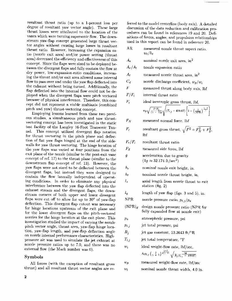
Symbols
All forces (with tile exception of resultant gross wp
thrust) and all resultant thrust vector angles are re- wt
2
ferred to the model centerline (body axis). A detailed
discussion of the data reduction and calibration pro-cedures can be found in references 19 and 20. Defi-
nitions of forces, angles, and propulsion relationshipsused in this report can be found in reference 20.
measured nozzle throat aspect ratio,
wt/ht
nominal nozzle exit area, in 2
nozzle expansion ratio
measured nozzle throat area, in 2
nozzle discharge coefficient, wp/wi
measured thrust along body axis, lbf
internal thrust ratio
ideal isentropic gross thrust, lbf,
p _ (r,,j2_n
measured normal force, lbf
resultant gross thrust, v/F 2 + F_ + F_,lbf
resultant thrust ratio
measured side force, lbf
acceleration due to gravity
(lg _ 32.174 ft/sec 2)
nonfinal nozzle exit height, in.
nominal nozzle throat height, in.
axial length from nozzle throat to exit
station (fig. 2)
length of yaw flap (figs. 3 and 5), in.
nozzle pressure ratio, Pt,j/Pa
design nozzle pressure ratio (NPR for
fully expanded flow at nozzle exit)
atmospheric pressure, psi
jet total pressure, psi
jet gas constant, 53.3643 ft/°R
jet total temperature, °F
ideal weight-flow rate, lbf/sec,
measured weight-flow rate, lbf/sec
nominal nozzle throat width, 4.0 in.

Xe axial distance from nozzle connect
station to nozzle exit (fig. 2), 4.55 in.
Xs axial distance from nozzle connect
station to yaw-flap hinge location (alsowhere sidewalls end and divergent flap
cutout begins (fig. 2)), in.
xt axial distance from nozzle connect
station to nozzle throat (fig. 2), in.
_f ratio of specific heats, 1.3997 for air
@ resultant pitch thrust vector angle,
tan-1 _t_, deg
_r resultant thrust vector angle due to
combined pitch and yaw thrust vectoring,
5v,p geometric pitch vector angle measuredfrom model centerline (positive for
downward deflection angles), based on
average rotation of upper and lower
flaps, deg
6v,v geometric yaw vector angle, flap deflec-tion about hinge location (positive to left
looking upstream), deg
div resultant yaw thrust vector angle,
tan -1 _, degx
7/r_r vectoring performance-effectivenessparameter for simultaneous pitch and
yaw thrust vectoring,
[(Fr/fi)unvectored - (fr/Fi)vectored ] /(Sr,per degree
r/r% vectoring performance-effectivenessparameter for yaw thrust vectoring,
I( f r/ Fi)unvectored -- ( Fr / Fi)vectored] /1_._1,
per degree
Abbreviations:
A/B afterburning
approx, approximate
Conf. configuration
Conv. convergent
Div. divergent
Sta. model station, in.
2-D C-D two-dimensional convergent-divergent
Apparatus and Methods
Description of Static Test Facility
Model testing was conducted in the static test
facility of the Langley 16-Foot Transonic Tunnel
(ref. 19). The model was located in a large room
where the jet exhaust from a sinmlated single-engine
propulsion system was vented to the atmosphere.
This facility utilized the same clean, dry air supplyas that used in the 16-Foot Transonic Tunnel and a
similar air control system, which included valving,
filters, and a heat exchanger (used to maintain aconstant temperature in the high-pressure plenum).
(See fig. l(a).) A remotely located control roomcontained the controls for the airflow valves and a
closed-circuit television to observe the model when
the jet was operating.
Single-Engine Propulsion Simulation
System
A sketch is presented in figure l(a) of the single-
engine air-powered nacelle model on which the vari-
ous nozzle configurations with pitch and yaw thrust-vectoring capability were tested. A photograph of the
propulsion simulation system is shown in figure l(b)
with a typical unvectored, dry power 2-D C-D con-
figuration installed.
An external high-pressure air system provideda continuous flow of clean, dry air at a controlled
temperature of approximately 85°F. The pressure
was varied during jet simulation to provide a noz-
zle pressure ratio up to 7.0 (or until balance limits
were reached). The model was secured on a dollymounted support strut through which the pressur-
ized air was routed. The air traveled through tubing
in the strut into a high-pressure plenum chamber.
From there the air was discharged perpendicularly
into the low-pressure plenum through eight multi-
holed, equally spaced sonic nozzles located around
the high-pressure plenum. (See fig. l(a).) This air-
flow system was designed to minimize any forces in-
curred during the transfer of axial momentum as theair is passed from the nonmetrie (not on the balance)
high-pressure plenum to the metric (on the balance)low-pressure plenum. A pair of flexible metal bel-
lows (shown in fig. 1(c)) scaled the air system be-
tween the metric and nonmetric parts of the model
and compensated for any axial force caused by pres-
surization. The low-pressure air then passed from the
circular low-pressure plenum through a circular-to-
rectangular transition section, a multiple-orifice rec-
tangular choke plate (flow straightener), and a rec-
tangular instrumentation section, which was commonfor all nozzle models tested. The instrumentation
section was common in geometry to the nozzle air-
flow entrance (nozzle connect section). All nozzle
configurations were attached to the instrumentation
section at model station (Sta.) 41.13.
3

Nozzle Design
At unvectored conditions, 2-D C-D nozzles consist
of two pairs of symmetric upper and lower flaps.
The flow is compressed and accelerated at subsonic
speeds by tile convergent flaps. Once tile flow is
choked at the throat, it is expanded by the divergent
flaps. At the design nozzle pressure ratio (NPR)d ,
the flow is fully expanded at the exit plane of the
nozzle. (The static pressure at the exit is equal to tile
ambient static pressure.) The sidewalls are flat and
contain tile flow laterally. To achieve positive thrust
vectoring in the pitch plane, the divergent flaps are
rotated downward (the upper flap toward the nozzlecenterline). A schematic of a typical 2-D C-D nozzle
in the forward-thrust (no pitch) and positive pitch
thrust-vectored modes is shown in figure 2(a).
Four baseline nozzle configurations were tested.
Two of the baseline nozzles simulated a dry power
setting and two represented afterburning (A/B)
power. Both forward-thrust (no pitch) and pitch
thrust-vectored modes were examined for each power
setting. The forward-thrust (6v,p = 0°) dry power
baseline nozzle used in the current test (fig. 2(b))had previously been investigated. (See refs. 12 (con-
figuration C1) and 13 (configuration S1).) The pitch
thrust-vectored baseline nozzle shown in figure 2(c)
had not been previously tested. It was designed us-
ing the geometry of the forward-thrust nozzle andassumed a constant length from the center of flap
rotation at the throat plane to the trailing edge ofthe divergent flap. (See fig. 2(a).) Using the geome-
try of the forward-thrust nozzle, this line was rotated
downward 20 ° from its original inclination to the hor-
izontal. Because of the design of the flap, a nominal
deflection of 20 ° caused the upper divergent flap tobe rotated downward by 19.33 ° and the lower diver-
gent flap to be rotated downward by 19.73 ° from the
common starting divergence angle of 1.17 ° . (Note
that the divergent flap length changed.) The averageof these rotations resulted in a geometric pitch vector
angle I_t,,p of 19.53 °.
The A/B power baseline nozzle (Sv,p = 0°) hadalso been investigated previously with nozzle inter-
nal performance reported in references 10 (configu-ration A1) and 13 (configuration $9). The geometry
for this nozzle is presented in figure 2(d). Similarly,
the geometry for the A/B pitch thrust-vectored base-
line nozzle (Sv,p = 20.26 °) is given in figure 2(e). Thenozzle internal performance for this configuration is
documented in references 10 (configuration A1V20)
and 13 (configuration $15). All four of the base-
line nozzles had full divergent flaps and sidewalls
that ended at the (unvectored) nozzle exit plane,that is, (xs - xt)/Is = 1.00. The reduction in mea-
sured throat area from the forward-thrust nozzles to
the pitch-vectored nozzles (dry and A/B power) wascaused by changes in the nozzle internal geometry
due to rotation of tile divergent flaps. As noted in fig-
ures 2(b) to 2(e), each baseline nozzle geometry had
three derivatives corresponding to the three hinge lo-
cations upstream of the exit plane. This was neces-
sary because of the varying amount of divergent flap
cutout associated with each hinge location.
In this investigation, thrust vectoring in the yaw
plane was accomplished by deflecting full-sidewall-
height yaw flaps about a vertical hinge line. Asshown in figure 3, one flap was vectored into the
internal exhaust flow and the other flap was vectored
the same amount away from the exhaust. The yaw
flaps were tested at four hinge locations illustrated in
figure 4, starting at the nozzle exit (Sta. 45.68) andprogressing upstream in equal increments. The non-
dimensional term (xs- xt)/ls describes this yaw-
flap hinge location as a percentage of the nozzle
divergent flap length, where (x_- xt)/1._ = 1.00
denotes the hinge at the nozzle exit, (x.s - xt)/ls = 0
denotes the hinge at the throat t)lane of the dry power
_v,p = 0 ° baseline nozzle, and the other two values(0.67 and 0.33) denote locations between the exit
and the throat. Although the axial positions of the
four hinge locations (Xs) were fixed throughout the
test, the A/B power nozzles had a different throat
location (zt = 2.3.5 in. as seen in fig. 2((t)). The
difference in throat location caused a change in the
value of ls because the exit plane location was fixed.
Therefore, the values of hinge location for the A/Bpower nozzles are slightly different from the values
for the dry power nozzles. (See fig. 4.) For theA/B power nozzles, the values of hinge location were
(xs - xt)/Is = 1.00, 0.66,0.31, and -0.03. A hinge
location of -0.03 implies that the hinge is locatedjust upstream of the throat plane.
In order to allow for yaw-flap deflection at the
three hinge locations upstream of the exit plane,
portions of both upper and lower divergent flaps hadto be cut out (fig. 4). This cutout was made on
both sides of the upper and lower flaps to allow
for both positive and negative yaw vector angles.The cutout started at the edge of the upper and
lower flaps where the yaw-flap hinge was located
(at the end of the sidewall) and ended at the exit
plane. Enough divergent flap was removed to allow
for a maximum of 30 ° of yaw-flap deflection in either
direction at both forward-thrust and pitch thrust-vectored conditions. (It is important to note that the
cutout, once designed into a full-scale nozzle, would
not vary. The aircraft, would always fly with thisdivergent flap cutout, and the yaw-flap length wouldremain fixed. Installed performance studies would be

requiredto fix the yaw-flaphingelocationandflaplength.)
Threedifferentlengthsof sidewallyawflapswereusedin this investigation(fig. 5), tile longestofwhichwasequalto theaxiallengthfromthethroatto the exit planeof the dry powerbaselinenozzle(ly = 2.27in.). (In this case,l_Jl_ = 1.00 for drypower, and 1.03 for A/B power.) The second and
third sets were two-thirds (ISls = 0.67 for dry powerand 0.69 for A/B power) and one-third (lu/ls = 0.33
for dry power and 0.34 for A/B power) the length
of tile long set, respectively. Each of these three
different sets of yaw flaps could be vectored at yaw
angles of 0 °, -20 °, and -30 ° . Not all yaw flapswere tested at each hinge location. Table I shows the
combinations of yaw-flap hinge location, flap length,
and flap deflection angle for which data are available.
Figure 6(a) shows photographs of four dry powernozzle configurations with the same yaw-flap length
(ly/1._ = 0.67 and hv,y = 0°) installed at the fourdifferent hinge locations. Sketches of these config-
urations are presented in figure 6(b) and are typi-
cal of sketches used throughout the data presenta-tion to aid the reader in recognizing the yaw-flap
hinge location, flap length, and flap deflection an-
gle. Figure 7 shows photographs of some typical yaw-
vectoring configurations with the trailing edge of the
yaw" flaps ending at the exit plane. Three hinge lo-cations and yaw-flap lengths are shown.
Instrumentation
The weight-flow rate of the high-pressure air
supplied to the model was deternfined from tem-
perature and pressure measurements in the high-
pressure plenum and was calibrated with standardaxisymmetric nozzles. (See ref. 21.) Nine total-
pressure probes were attached to three rakes locatedin the instrumentation section. A thermocouple was
also positioned in the instrumentation section tomeasure the jet total temperature. (See fig. l(a).) An
area-weighted average of the nine jet total-pressuremeasurements was used for the jet total pressure.
Measured values of the temperature and pressure in
the instrumentation section, along with the measured
throat area, were used to compute the ideal weight-flow rate. Details of the measured and ideal weight-
flow rate calculations can be found in reference 20.
A six-component strain-gauge balance was usedto measure the forces and moments on the model
downstream of station 20.50. The balance-moinent
reference center was located at station 26.54. The
accuracy of force balance readings is quoted at
±0.5 percent of full-scale values. The full-scale val-
ues for the balance used in this investigation are as
follows: axial force, 500 lb; normal force, +500 lb;
and side force, ±350 lb.
Data Reduction
All data were recorded on magnetic tape and
taken in ascending order of Pt,j. Fifty frames of data,taken at a rate of 10 frames per second, were used to
compute an average steady-state value for each data
point.. The basic performance parameters used in
the presentation of results were internal thrust ratio
F/Fi, resultant thrust ratio Fr/Fi, resultant pitch
thrust vector angle 5p, resultant yaw thrust vector
angle 5q, and discharge coefficient Cd.Tile internal thrust ratio F/Fi is tile ratio of
measured nozzle thrust along the body axis to ideal
thrust, where ideal thrust is based upon measured
weight-flow rate wp, jet total temperature Tt,a, andnozzle pressure ratio NPR. The balance axial-force
measurement, from which the actual nozzle thrust F
is subsequently obtained, is initially corrected for bal-
ance interactions. Although the bellows arrangement
was designed to elinfinate pressure and momentunlinteractions with the balance, small bellows tares on
the six balance compoimnts still exist. These tares
result from a small pressure difference between theends of the bellows when internal velocities are high
and from small differences in the spring constants ofthe forward and aft bellows when the bellows are
pressurized. These bellows tares were deternfined
by testing standard axisymmetric calibration nozzleswith known performance over a range of expected
longitudinal and lateral forces and moments. Thebalance data were then corrected in a rammer simi-
lar to that. discussed in reference 7 to obtain thrust
along tile body axis F, normal force FN, and side
force F5,. The resultant thrust ratio Fr/F'i, resultant
pitch vector angle 5p, and resultant yaw vector angle
5y were then determined from these corrected bal-ance data. A more detailed discussion of the data
reduction process can be found in references 19 and20.
The resultant thrust ratio Fr/Fi is tile resultant
gross thrust divided by the ideal isentropic gross
thrust. Resultant gross thrust is obtained froin
the measured axial (thrust along the l)ody axis),normal, and side components of the jet resultant
force. As long as the exhaust flow is unvectoredin either the longitudinal or lateral direction, F/Fi
and Fr/F i are equal. From the definitions of F andFr, it is obvious that the thrust along the body
axis F includes losses that result fi'om turning the
thrust vector away from the axial direction, whereas
the resultant gross thrust Fr does not. The lossesincluded in both thrust terms F and Fr are caused
by friction and pressure drags associated with the
thrust-vectoringhardware.Resultantthrust vectoranglesin the longitudinal(pitch)plane6pand thelateral(yaw)plane5y are presented for evaluating theexhaust-flow turning capability of the various thrust-
vectored nozzle configurations.
The nozzle discharge coefficient C d is the ratio
of measured weight-flow rate to ideal weight-flow
rate, where ideal weight-flow rate is dependent upon
jet total pressure Pt,j, jet total temperature Tt,j,and measured nozzle throat area At. The nozzle
discharge coefficient reflects the ability of a nozzle to
pass weight flow and is reduced by any momentum
and vena contracta losses (ref. 22).In order to compare the results from the current
investigation with the results obtained from previous
investigations, several thrust-vectoring performance-
effectiveness parameters defined in reference 16 were
used. These parameters, r]rby (for pure yaw thrust-
vectoring concepts) and 6r and rlr_T (for simultane-
ous pitch and yaw thrust-vectoring concepts), were
computed from data obtained as close to (NPR)d aspossible. They serve as figures of merit by indicating
the effectiveness of a thrust-vectoring concept; thatis, they provide a value for the loss in resultant thrust
ratio per degree of resultant thrust vector angle.
6_,,p = 20.26°:(xs - xt)/ls = 1.00 ......... 22
(Xs - xt)/l._ = 0.66 ......... 23
(xs - xt)/ls = 0.31 ......... 24
(xs - xt)/Is = -0.03 ........ 25
Summary of effects of yaw-flap deflection on
dry power nozzle ............ 26
Effect of varying yaw-flap length on nozzle
internal performance:
_v,y = 0° ............... 27
_v,y = -30 ° .............. 28
Effect of varying yaw-flap hinge location on
nozzle internal performance
(6v,y = -30 °) ............. 29
Summary of effects of yaw-flap length andhinge location on nozzle internal
performance (6v,y = -30 °) ........ 30
Effect of pitch thrust vectoring on nozzleinternal performance .......... 31
Comparison of nozzle yaw thrust-vectoring
concepts ............... 32
Comparison of combined pitch and yaw
thrust-vectoring concepts ........ 33
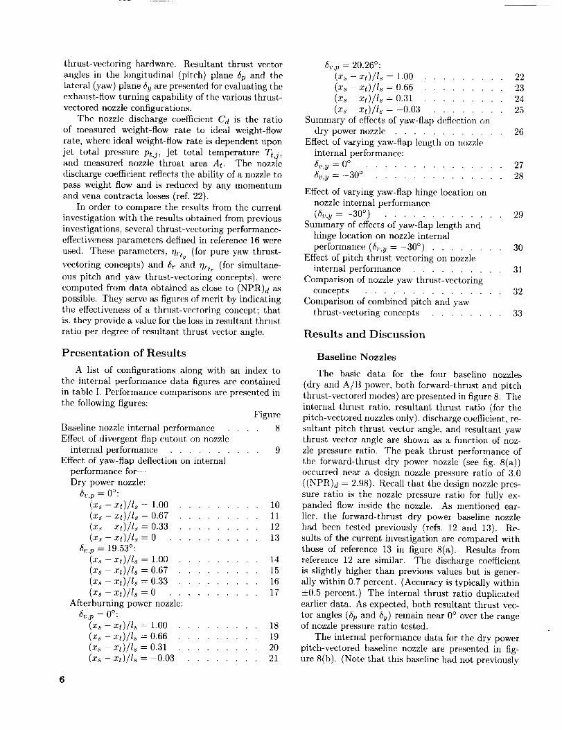
Results and Discussion
Presentation of Results
A list of configurations along with an index to
the internal performance data figures are contained
in table I. Performance comparisons are presented in
the following figures:
Figure
Baseline nozzle internal performance .... 8
Effect of divergent flap cutout on nozzle
internal performance .......... 9Effect of yaw-flap deflection on internal
performance for
Dry power nozzle:
t_v,p = 0°:(xs - xt)/ls = 1.00 ......... 10
(Xs - xt)/l._ = 0.67 ......... 11
(xs - xt)/ls = 0.33 ......... 12
(xs - xt)/ls = 0 .......... 13
6v,p = 19.53°:(xs -- xt)/ls = 1.00 ......... 14
(Xs -- xt)/ls = 0.67 ......... 15
(xs - xt)/ls = 0.33 ......... 16
(xs -- xt)/Is = 0 .......... 17
Afterburning power nozzle:
6v,p = 0°:(Xs - xt)/Is = 1.00 ......... 18
(Xs - xt)/ls = 0.66 ......... 19
(Xs - xt)/ls = 0.31 ......... 20(Xs -- xt)/l._ = --0.03 ........ 21
Baseline Nozzles
The basic data for the four baseline nozzles
(dry and A/B power, both forward-thrust and pitchthrust-vectored modes) are presented in figure 8. The
internal thrust ratio, resultant thrust ratio (for thepitch-vectored nozzles only), discharge coefficient, re-
sultant pitch thrust vector angle, and resultant yawthrust vector angle are shown as a function of noz-
zle pressure ratio. The peak thrust performance of
the forward-thrust dry power nozzle (see fig. 8(a))occurred near a design nozzle pressure ratio of 3.0
((NPR)d = 2.98). Recall that the design nozzle pres-
sure ratio is the nozzle pressure ratio for fully ex-
panded flow inside the nozzle. As mentioned ear-
lier, the forward-thrust dry power baseline nozzle
had been tested previously (refs. 12 and 13). Re-
sults of the current investigation are compared with
those of reference 13 in figure 8(a). Results from
reference 12 are similar. The discharge coefficient
is slightly higher than previous values but is gener-
ally within 0.7 percent. (Accuracy is typically within
=t=0.5 percent.) The internal thrust ratio duplicatedearlier data. As expected, both resultant thrust vec-
tor angles (6p and 5y) remain near 0° over the rangeof nozzle pressure ratio tested.
The internal performance data for the dry power
pitch-vectored baseline nozzle are presented in fig-ure 8(b). (Note that this baseline had not previously
6

beentested.) Thepeakof the resultantthrust ra-tio curveoccurredbetweena nozzlepressureratioof 4.0and5.0 ((NPR)d= 4.42). A comparison of
these two baseline nozzles (vectored and unvectored)
shows less than a 0.5-percent decrease in peak resul-
tant thrust ratio because of turning losses associated
with pitch vectoring. (For tile forward-thrust nozzle,
the internal thrust ratio equals the resultant thrust
ratio.) Static pressure data from several earlier inves-
tigations on pitch thrust-vectored 2-D C-D nozzleshave shown that the throat plane rotates from the
unvectored position to a location where it is nearlyperpendicular to tile upper divergent flap, where the
minimum geometric cross-sectional area occurs. (See
the geometry in fig. 2 and also see refs. 7 and 11.)Consequently, the internal flow is turned at subsonic
speeds which proves to be efficient, as can be seen by
the small loss in peak resultant thrust ratio betweenthese two nozzles.
At low nozzle pressure ratios, the resultant pitch
vector angle for the dry power pitch-vectored baseline
nozzle is higher than the design pitch vector angle of19.53 ° . Overturning at low nozzle pressure ratios is
typical of pitch thrust-vectored 2-D C-D nozzles at.
dry power operating conditions. This turning an-
gle decreases with increasing pressure ratio to val-
ues below the design ("metal") angle. As noted in
reference 10, this change in thrust angularity with
increasing nozzle pressure ratio is common in non-
axisymmetric nozzles whenever one flap is longer
than the other with respect to tile flow centerline.
(See fig. 2(e).) This difference in flap length pro-
rides surfaces of unequal length for the flow to ex-
pand upon so that one side of the internal flow is
contained longer by a flap while the other side of theexhaust flow is unbounded.
There was a 1.5-percent decrease in discharge co-
efficient due to pitch vectoring the dry power nozzlefrom 0° to 19.53 °. These losses are associated with
changes in throat position when the nozzle was pitchvectored.
Both A/B power baseline nozzles had been tested
previously, and their internal performance is docu-mented in references 10 and 13. Because of limita-
tions on the force balance, data were not obtained for
values of NPt/at and above peak performance levels.
The internal performance of the A/B power forward-
thrust baseline nozzle is presented in figure 8(c) andcompared with results from reference 13. Although
(NPR)d = 4.54 for this nozzle, data presented at themaximum NPR of 4.5 do not indicate that the perfor-
mance peak has been attained. In fact, results from
reference 13 indicate that peak performance occurred
at NPR = 5.0. Results from the current investiga-
tion for internal thrust ratio and discharge coefficient
agree with those of reference 13. As expected, both
resultant thrust vector angles remain near 0° for the
NPR range tested.
The internal performance of the A/B power pitch-
vectored baseline nozzle is compared with results
from reference 10 in figure 8(d). Data below NPR
= 4.0 are similar, but slight differences occur in
F/Fi, Fr/Fi, and (hp for the data points above NPR= 4.0. As discussed in reference 10, this nozzle
experiences flow" separation on the lower divergent
flap at nozzle pressure ratios below design ((NPR)d = .
6.33), and reattaehment (which occurs between NPR= 3.5 and 4.0) of the exhaust to the lower flap did
not occur at the same pressure ratio as before. A
difference of approximately 1 percent, in F/F i and 1°
in @ can be seen in figure 8(d). It is likely that thisflow separation on tile lower divergent flap at a low
NPR is caused in part by the large angle that the flow
is turned on the lower flap. As the pressure gradient
increases between the upper and lower divergent flaps
with increasing NPR (see ref. 10), the internal flowis forced to turn more in the direction of the lower
divergent flap surface. Between an NPIt of 3.5 and
4.0, the flow reattaches to the lower flap resulting
in larger turning angles. This reattachment causes
a large drop in F/Fi (over 5 percent) because the
exhaust flow is being turned farther away from theaxial direction. Concurrently, there is an increase of
7° in @. As expected, resultant yaw vector anglesremain near 0° over the range of pressure ratiostested.
Effects of Divergent Flap Cutout
The effects of divergent flap cutout on nozzle
internal performance for forward-thrust and pitch
thrust-vectored nozzles are presented in figures 9(a)
and 9(b) for dry power configurations and in fig-
ures 9(c) and 9(d) for A/B power configurations. Thehinge location has been successively moved back to
the throat while holding the yaw-flap trailing edge at
the exit such that. [(xs - xt)/Is] + l_Jls = 1.00. (Seethe symbol key in fig. 9.) Note that the yaw flapswere undeflected.
Dry power nozzles. As discussed previously,hinge locations upstream of the exit plane required
a cutout of the downstream corners of the divergent
flaps for yaw-vectoring capability. Moving the hinge
back to (xs - xt)/Is = 0.33 had no effect on nozzleinternal thrust performance. However, locating the
hinge at the throat ((x_ - xt)/ls = 0) resulted in a
0.5-percent loss in internal thrust ratio near the base-
line (NPR)d of 2.98. This loss in thrust ratio in-
creases as nozzle pressure ratio increases and is due to
a portion of the exhaust flow expanding through the
7

cutoutin thedivergentflaps(lessefficiently).Movingthehingebackto the throat (denotedby triangularsymbols)alsoresultedin a decreasein theeffectiveexpansionratio A_./At since the peak performance is
occurring at a lower nozzle pressure ratio. Therefore,
at higher values of NPR, this configuration is also ex-
periencing increased underexpansion losses because
it is operating farther from the design nozzle pres-sure ratio. These results are similar to those of ref-
erence 2a for an axisymmetric convergent-divergent
nozzle with slots in the divergent flaps. It is impor-
tant to note that these forward-thrust configurations
represent the nozzle position during cruise (which is
generally the majority of an aircraft flight profile).
As always, performance/weight trades exist, and the
adverse effect of a small loss in thrust ratio (as mea-
sured for the largest cutout) due to divergent flap
cutout might be offset by a decrease in the nozzle
weight and internal nozzle surface area to be cooled.
A decrease in discharge coefficient of 0.6 percent
can be seen from the baseline (circular symbols) to
configurations with divergent flap cutout (yaw flaps
hinged upstream of the exit). It is not understood
what caused this decrease in Cd, but two possiblereasons are presented below. The decrease in C_t
might be due to a snmll change ill geoInetry upstream
of the nozzle throat in the convergent region ofthe nozzle. Evidence of this can be seen in tile
repeatability of data for the three configurations with
increasing divergent flap cutout. However, removal ofthe downstream corners of the divergent flaps might
have also affected C d by altering the position and,therefore, the area of the throat.
Tile pitch thrust-vectored configurations
(fig. 9(b)) show a decreasing trend in resultant thrust
ratio due to increasing divergent flap cutout. Locat-
ing the yaw-flap hinge at (xs - xt)/ls = 0 results in a2.4-percent loss in resultant thrust ratio at a nozzle
pressure ratio of 4.0 (fig. 9(b)). Again, it is proba-
ble that these losses are occurring because a portion
of the exhaust flow is expanding through the cutout
in the divergent flaps, and the nozzle has less diver-
gent flap surface area on which the expanding flow
can produce thrust. It is again evident that tile effec-
tive expansion ratio has decreased because the nozzle
pressure ratio at which peak performance occurs hasdecreased.
Increased divergent flap cutout causes increased
internal thrust ratio and decreased resultant pitch
vector angle at low nozzle pressure ratios (and also
decreased thrust ratio and increased vector angle
at higher nozzle pressure ratios) when comparedwith results from the baseline nozzle. The results
from reference 11 for a pitch-vectored nozzle with
a similar geometry (to the current baseline nozzle)
show similar data trends, but the effect was caused
by sidewall cutback instead of divergent flap cutout.TILe increased thrust ratio at lower nozzle pressure
ratios in reference 11 was due in part to a slightincrease in static pressure due to sidewall cutback
that was greater on the lower divergent flap than
on the upper flap. In this configuration, as is the
case in the current, investigation, at positive pitch-
vectored conditions (lower flap down) tile upper flap
was a forward-facing surface and the lower flap was
a rearward-facing surface. The increase in pressure
on the upper flap caused a loss in axial force that
was overcome by a gain in axial force due to a larger
increase in pressure on the lower flap. The result was
an overall increased internal thrust ratio. This slight
pressure increase also caused a reduction in normal
force which, when coupled with the increased axial
force, produced a lower resultant pitch thrust vector
angle. Although no static pressures were measured in
the current investigation, the results of reference 11
are similar to those presented in figure 9(b), and itis possible that this same pressure phenomenon is
occurring at low nozzle pressure ratios because of
venting of the exhaust flow.
In the current investigation, the loss in axial force
at higher nozzle pressure ratios due to a portion of
the flow expanding through the divergent flap cutoutresults in a reduced internal thrust ratio. However,
this loss in axial force, when coupled with an increase
in nornml force, gives a larger resultant pitch thrust
vector angle. The reason for this increase in normalforce is not known.
There is very little change in discharge coefficient
due to the divergent flap cutout of the pitch-vectored
nozzle for hinge locations downstream of the throat.
The yaw-flap hinge location at (x._ -xt)/1._ = 0
is believed to be upstream of the baseline pitch-
vectored nozzle throat, and consequently there isa change in C_t for this configuration as seen in
figure 9(b). This increase in C d is probably a result
of differences in measured and actual physical throatareas. It is likely that the throat plane for this
configuration is not as skewed to the nozzle centerline
(as the baseline throat was) because of ventilation
through the cutout in the upper divergent flap. As
a result, the actual throat area is probably larger
than the measured value of At used to compute w i.
Therefore, Cd may be artificially high. If the true
physical throat area could be measured, C d wouldlikely be lower than the values shown.
A/B power nozzles. The effect of the divergent
flap cutout on unvectored A/B nozzle internal perfor-
mance is presented in figure 9(c). As discussed pre-
viously (and noted in several references), increasing

nozzleventilation,by either sidewall cutback or di-
vergent flap cutout (as in this paper), tends to reduce
tile effective expansion ratio. At lower values of NPR,
ovcrexpansion losses are simply reduced by vent.ila-tion. Therefore, the highest internal performance (at.
lower values of NPR) wouht be expected for the con-
figuration with the largest cutout. Conversely, at
higher values of NPR the most ventilated configu-rations are operating farther from the design noz-
zle pressure ratio; increased underexpansion lossesdrive these configurations to lower performance lev-els. A close exanfination of the internal performance
data would also suggest that. peak performance lev-
els decrease slightly with increasing cutout. These
losses are probably associated with local changes in
flap static pressure distribution resulting from flap
cutout. A (tivergent flap cutout of the forward-thrust
A/B power nozzle for a hinge location slightly up-stream of the throat resulted in a loss of approxi-
mately 1 percent when compared with the baseline
at an overexpanded nozzle pressure ratio of 4.5.
Pitch-vectored nozzle performance for A/B power
configurations with varying amounts of divergent flap
cutout is presented in figure 9((t). All data are at
overexpanded flow conditions_ and therefore these
configurations have not reached their peak perfor-
mance levels. Data trends for F/F i and @ at an
NPR below that for peak performance indicate that
increasing flap cutout causes an increase in F/F_ and
a decrease in @ when compared with results from thebaseline nozzle. Flap cutout corresponding to a hinge
location of -0.03 probably prevents reattachment of
the separated flow on the lower divergent flap (as dis-
cussed earlier and as indicated by the lower values of
@). At NPR = 4.0 (near where reattachment occurson the baseline nozzle), this continued flow separa-
tion leads to increased F/Fi and decreased /_p be-cause the exhaust is not being turned away from theaxial direction as nmch as before. Resultant thrust
ratios at a nozzle pressure ratio near 5.0 (the nozzle
is overexpanded at this NPIt) are not affected by flap
cutout.
Although a slight increase in discharge coefficient
can be seen for this hinge location upstream of the
throat, values are generally within data-measurement
accuracy.
Effects of Yaw-Flap Deflection
Performance characteristics for yaw thrust-
vectored configurations and combined pitch and yawthrust-vectored configurations arc presented in fig-
ures 10 to 17 for the dry power nozzles and in fig-
ures 18 to 25 for the A/B power nozzles. Each figure
presents the effects of yaw-flap deflection on nozzle
internal performance data for a constant hinge loca-
tion with yaw flaps of different lengths.
Dry power nozzles. In general, both internal
thrust ratio F/Fi and resultant thrust ratio Fr/F_
were significantly decreased by yaw-flap deflection.
The losses experienced in F/Fi are certainly expected
because flow is being directed away from the axial
direction by the yaw flaps. Losses in Fr/Fi indicate
that the yaw flaps are not, 100 percent efficient at
turning the exhaust flow. It is important to note
that the magnitude of these turning losses did not
necessarily increase with increasing b_,,y. In fact. for
configurations with the yaw faps hinged upstream of
the exit, the 6_,y = -30 ° deflections generally pro-
vided higher resultant thrust ratios than the -20 °
yaw-flap-deflection cases. (See fig. ll(a), for exam-
ple.) Further insight, into the reasons for this increase
in performance can be gained by examination of thenozzle discharge coefficient, data.
For all post-exit yaw-vectoring situations (figs. l0
and 14) and one pitch thrust-vectored configuration
with the yaw-flap hinge located just upst.ream of
the exit (fig. 15), the nozzle discharge coefficient
was independent of yaw-flap deflection. However, in
general, yaw-flap (tcfleetion about a hinge location
ui)stream of the exit plane caused losses in nozzle
discharge coefficient. (See fig. 13. for example.)
Losses in C d ranged from 0 to 3 percent for the 5_,y =-20 ° cases and up to 14 percent when the yaw flap
was deflected -30 °. These losses in C d for the yaw-
vectored configurations were caused t)y a shift in the
physical throat location from the expected location
(fig. 2(b)) to a position farther downstream andskewed relative to the nozzle ecnterline. Obviously,
the effective physical throat area was nmch smallerthan the nominal unvectored throat area used t.o
compute ideal weight-flow rate. For a given nozzle
pressure ratio, a smaller effective throat area reduces
the amount of weight flow that can pass through the
throat. Therefore, the discharge coefficient, that is,the ratio of measured to ideal weight-flow rate, was
decreased.
As a result of this rotation (skewing) of the throat
plane, it is likely that an increased amount of theinternal flow was turned at subsonic speeds. Since
subsonic flow turning is more efficient than super-
sonic flow turning (and based on the nozzle dis-
charge coefficient data shown in figs. 10 to 17), it is
believed that the -30 ° yaw-flap deflection providesmuch more subsonic flow turning (in the side-force
direction) than the -20 ° deflection. As a result, the
5v,y = -30° ease could be expected to be the moreefficient yaw-vectoring ease (higher Fr/Fi).

In addition, increasing the yaw-flap deflectionfrom -20 ° to -30 ° should eliminate some flow ven-
tilation (present on the _Sv,v = -20 ° case) out of the
gap between the yaw flap and the upper and lower
divergent flaps. This ventilation, as discussed pre-viously, is believed to result in some thrust loss. It
also appears that deflection of the yaw flaps to -30 °
resulted in a decrease in the effective expansion ra-
tio (Ae/At) of a yaw thrust-vectored configuration
because peak performance (Fr/Fi) for this case gen-erally occurred at a lower nozzle pressure ratio than
with the 6v.y = 0° configuration.
Resultant pitch and yaw thrust vector angles are
also presented in figures 10 to 17. As seen, yaw-flapdeflection had little effect on resultant pitch vector
angle for the unvectored configurations (_v,p = 0°)and the post-exit, yaw-flap pitch-vectored configura-
tions (figs. 10 to 14), but it caused decreases in 6pon the combined pitch and yaw vectoring cases withhinge locations upstream of the exit. These decreases
became larger as _Sv,ywas increased. It would appear
that the yaw flaps are generating side force at the ex-pense of both normal force and axial force on these
combined pitch and yaw thrust-vectored configura-
tions. The yaw flaps generally do provide the last
flow-turning mechanism to affect the flow, and hence
the above result might be expected. Resultant yaw
vector angle was obviously affected by yaw-flap de-
flection angle. Increases in 6v,y did provide increased
6y. In all cases, however, measured yaw vector an-
gles were less than the geometric deflection angles.
The largest resultant yaw vector angle (-24.3 ° ) isshown in figure 17(c) for a combined pitch and yaw
thrust-vectored configuration with a yaw-flap hinge
location of (xs - xt)/ls = 0 and a yaw-flap length of
ly/ls = 1.00.
A/B power nozzles. Results similar to the dry
power nozzle data can be seen for the A/B power
configurations in figures 18 to 25. However, it is im-
portant to note that all data for these A/B configura-tions are at overexpanded flow conditions because of
limitations on the force balance. In general, yaw-flap
deflection caused losses in internal thrust ratio F/F iand resultant thrust ratio Fr/Fi at nozzle pressure
ratios below design. Several configurations showed
an increase in Fr/Fi (up to 2 percent) because of
yaw-flap deflection at overexpanded nozzle pressure
ratios. (See fig. 20.) This result might be due in part
to a decrease in the effective expansion ratio of thenozzle, thereby decreasing the overexpansion losses
since the nozzle is operating closer to peak Fr/Fi.
Additionally, configurations tested with yaw-flap de-
flection angles of -20 ° and -30 ° (figs. 21, 24(b), and
25(c)) that also showed a decrease in nozzle discharge
coefficient indicated an increase in Fr/F i as the flapwas deflected from -20 ° to -30 ° . This result is at-
tributed to an increase in the amount of subsonic flow
turning in the side-force direction because of a skew-
ing of the nozzle throat plane (discussed previously).
Pitch thrust-vectored A/B configurations exhib-
ited changes in resultant pitch vector angle because of
yaw-flap deflection. In general, @ for the yaw-flap-deflected configurations was increased at low NPR
and decreased at high NPR when compared with the
undeflected yaw flaps. In figure 25(c), data at NPR =
1.8 show an increase of 5 ° in the resultant pitch vec-
tor angle associated with deflection of the yaw flaps
from 0° to -30 °. The generation of side force (by
yaw-flap deflection) resulted in an increase in mea-sured normal force and a decrease in measured axial
force. Again, the reasons for the increase in normalforce are not known.
Resultant yaw vector angle increased with in-
creasing yaw-flap deflection, as expected. However,
resultant yaw vector angle was always less than the
geometric metal (design) angle. The largest resultant
yaw vector angle (-20.9 ° ) is shown in figure 21 fora yaw-vectored configuration (no pitch) with a hinge
location (Xs - xt)/ls of -0.03 and a yaw-flap length
ly/ls of 1.03.
Figure 26 summarizes the effects of yaw-flap de-
flection on resultant thrust ratio and resultant pitch
vector angle (pitch-vectored nozzles only) for dry
power configurations from the current investigation
at a constant nozzle pressure ratio. Data are shown
at values of NPR near design for undeflected andfully deflected yaw flaps. (No data are shown for
yaw-flap deflections _v,y of -20 ° because of the lack
of configurations tested. The A/B power configura-tions have been intentionally left out because of a
lack of data at nozzle pressure ratios near peak per-formance.) For all configurations shown, losses expe-
rienced in Fr/F i due to yaw-flap deflection decreased
as the yaw-flap hinge location was moved upstream
from the exit plane toward the throat (decreasing val-ues of (Xs -xt)/Is). This result might be due to a de-
crease in the velocity of the flow that is being turnedin the side-force direction as the hinge location is
moved upstream. Note the significant resultant
thrust ratio losses on all the post-exit yaw-vectoring
configurations ((Xs -xt)/Is = 1.00). In general, dipwas decreased by yaw-flap deflection on dry power
pitch-vectored nozzle configurations at an NPR neardesign (fig. 26(b)).
Effects of Varying Yaw-Flap Length and
Yaw-Flap Hinge Location
The effects of increasing the length of undeflected
yaw flaps on the thrust and turning performance of
10

forward-thrustandpitch thrust-vectorednozzlesatdryandA/B powerarepresentedin figure27.A con-stanthingelocationof (x_- xt)/1._ = 1.00 has been
chosen as representative of the four hinge locations
investigated to illustrate the effects of increasing the
yaw-flap length. Note that data for these configura-
tions have been presented earlier in the section enti-tled "Effects of Yaw-Flap Deflection." Increasing the
length of the undeflected yaw flaps held at a constant
hinge location caused little or no change in the noz-
zle internal performance characteristics. Losses were
less than 0.5 percent for those configurations shown
in figures 27(a), 27(b), and 27(c), and they are con-sidered to be within measurement accuracy of the
balance. Only the data shown at a nozzle pressure
ratio of 4.0 for the A/B power pitch-vectored nozzle
(fig. 27(d)) exhibit, a significant change in nozzle per-formance because of increasing tile yaw-flap length.
It is obvious that the flow reattachment phenomenon
on the lower divergent flap of this nozzle (discussed
earlier) has been delayed. It is highly likely that
the differences are simply a function of the reattach-ment location. Note that the data at other pres-
sure ratios presented in figure 27(d) show less than
a +0.5-percent change due to increased yaw-flap
length. For this nozzle, increasing the length of unde-
fleeted yaw flaps has no effect on discharge coefficient
or resultant yaw thrust vector angle.
Nozzle thrust performance and resultant thrust
vector angles are presented in figure 28 for vary-
ing the yaw-flap length at a constant hinge location
for yaw thrust-vectored nozzles (yaw flaps deflected
to -30°). As before, dry and A/B power nozzles
with and without pitch thrust vectoring are shown
for a constant hinge location ((xs - xt)/ls = 0.33
for dry power and 0.31 for A/B power). Data for
the hinge location shown are typical (of the other
hinge locations tested) and indicate that increasingthe yaw-flap length decreased the internal and re-
sultant thrust ratios. Increasing the flap length al-
ways increased the resultant yaw vector angle. Thesetrends are due to an increase in side force and a de-
crease in axial force associated with increased yaw-
flap length. (This is true for all test data at or near
NPR = 4.0.) Increasing yaw-flap length at the three
hinge locations upstream of the exit decreased 5p on
the dry power configurations. Losses in discharge co-efficient appear to be more a function of hinge loca-
tion than of yaw-flap length, as is shown in figure 29.
Figure 29 presents data for varying the hinge lo-cation of a constant-length yaw flap on yaw-vectored
nozzle thrust performance and resultant thrust vec-
tor angles for dry power and A/B power nozzles with
and without pitch thrust vectoring. A flap length
ly/ls of 1.00 for dry power configurations (1.03 for
A/B power configurations) has been chosen as repre-sentative of the three lengths investigated. Configu-
rations with yaw flaps deflected about a hinge at the
exit plane exhibited the lowest, resultant thrust ratio
and lowest resultant yaw vector angle. For all config-
urations tested, moving the yaw-flap hinge upstream
of the exit plane reduced the losses in resultant thrust
ratio Fr/Fi due to yaw vectoring. These losses are
due in part. to the turning of supersonic flow. As the
hinge location is moved upstream from the exit, the
flow is turned at a lower supersonic velocity (or pos- .
sibly at subsonic speeds when the throat is skewed
to the nozzle centerline), and therefore flow-turning
losses caused by the vectored yaw flaps decrease. As
discussed previously, a result of the reduction in ef-
fec,tive throat area (due to the skewing of the throat
plane) is tile decrease in discharge coefficient seen in
figure 29. This loss in discharge coefficient occurs
for all three yaw-flap lengths on both dry and A/B
power nozzles.
Figure 30 summarizes resultant thrust ratio and
resultant thrust vector angles (except that 5p is not
shown for the b_:,p = 0° configurations) as a func-
tion of yaw-flap hinge location for the three different
yaw-flap lengths. (Note that the data presented hereconstitute one point at a single nozzle pressure ratio
for each yaw thrust-vectored configuration tested inthis investigation. Although dry power data are pre-
sented at an NPR close to peak performance, A/B
power data are at. overexpanded conditions. How-
ever, the data are the highest NPR data available
on the A/B power configurations.) Internal perfor-
mance data are presented in figures 30(a) and 30(b)
for tile dry power nozzle and in figures 30(c) and
30(d) for the A/B power nozzle.
Conclusions from figure 30 are generally made
from dry power data since not. enough A/B power
data are available for all the trends to be compared.
Yaw vectoring from flaps deflected about a hinge
location at the exit ((Zs -,rt)/ls = 1.00) causes
larger losses in resultant thrust ratio and produces
lower resultant yaw vector angles than vectoring
from .flaps deflected about the other three hinge
locations (upstream of the exit). It is also apparent.that reductions in nozzle performance (Fr/Fi) as a
function of yaw-flap length are much larger for yaw
flaps hinged at the exit than for the hinge locations
upstream of the exit. Upon further inspection of
figures 30(a) and 30(b), it becomes apparent that themaximum resultant yaw vector angle for a constant
yaw-flap length is produced by flaps that normally
have their trailing edge ending in the exit plane; i.e.,
the IJls = 0.33 flaps give maximum turning whenhinged at (zs - zt)/Is = 0.67, the ly/Is = 0.67 flaps
11

givemaximumturningwhenhingedat (xs- xt)/ls =
0.33, and the ly/Is = 1.00 flaps give maximmn
turning when hinged at (x,s - xt)/ls = 0. Thiswould seem to indicate that for maximum thrust-
voctoring capability, the hinge location and yaw-
flap length need to be chosen in such a way that
[(x_ - xt)/ls] + ly/Is = 1.00. (See fig. 7.)
An examination of data trends for a pure yaw
thrust-vectored configuration and combined pitchand yaw thrust-vectored configurations presented in
figures 30(a) and 30(b), respectively, leads to the fop
lowing hypothesis. A pair of yaw flaps hinged be-
tween (Xs -xt)/ls = 0.33 and 0 with the trailingedge extending to the exit would provide a compro-
mise that would probably produce values of resultant
thrust ratio slightly lower than those of flaps hinged
at (xs - xt)/ls = 0 for a pure yaw thrust-vectored
configuration and slightly higher than those of flaps
hinged at 0 on a combined pitch and yaw thrust-
vectored configuration. This hypothetical nozzle
would, in return, generate a compromised value ofresultant pitch thrust vector angle while maintain-
ing a large resultant yaw thrust vector angle that
would be slightly lower than that of flaps hinged at
the throat. Note that in comparison with the dry
power forward-thrust baseline nozzle (no divergent
flap cutout), this hypothetical combined pitch and
yaw thrust-vectored nozzle would have a resultant
thrust ratio that is 2 to 3 percent below that of the
forward-mode nozzle and yet be capable of generat-ing approximately 14° of resultant pitch thrust vector
angle and -20 ° of resultant yaw thrust vector angle.
Although only limited data exist for A/B power
nozzles (figs. 30(c) and 30(d)), it does appear from
observations of figure 30(d) that the "best" config-uration at A/B power also has a hinge location be-
tween (x_ - xt)/ls = 0.31 and -0.03.
The effect of pitch thrust vectoring on yaw-
vectored configurations is summarized in figure 31,where resultant thrust ratio and resultant yaw thrust
vector angle are shown as a function of yaw-flap hingelocation. Data are shown at a nozzle pressure ra-
tio near peak performance for dry power configura-
tions (NPR near design) in figure 31(a) and at over-
expanded conditions for A/B power cases (NPR less
than design) in figure 31(b). Pitch vectoring a yaw-
vectored nozzle decreased the resultant thrust ratio,
and this decrease was larger for the A/B nozzles.Pitch thrust vectoring had very little effect on the
resultant yaw vector angle. Recall from the previous
discussion, however, that yaw-flap deflection gener-
ally decreased the resultant pitch vector angle. Ide-ally from a controls standpoint, it would be desir-
12
able to have no cross coupling between the thrust-
vectoring processes.
Comparison of Thrust-Vectoring Concepts
The performance of pure yaw thrust vectoring (no
pitch) and combined pitch and yaw thrust-vectoring
dry power configurations from the current investiga-
tion is compared with the performance of the other
vectoring-nozzle concepts in figures 32 and 33, re-
spectively. Data in these figures are presented at a
nozzle pressure ratio near design for each conceptshown and therefore represent peak performance lev-
els. Data on the vertical axes are presented in theform of a ratio such that a value of 1.0 indicates a
measured resultant vector angle equal to the geo-
metric ("metal") vector angle. The vertical axes
then represent vectoring efficiency of the configura-
tions. The horizontal axes parameters indicate the
loss in resultant thrust ratio (relative to the unvec-
tored case) per degree of resultant thrust vector anglegenerated. A value of 0 indicates that there are no
resultant thrust ratio losses due to thrust vectoring.Note that the data presented here from the current
investigation are for the _v,y = -30 ° configurations,which produced less thrust loss per degree of flow
turning than the 5v,._ = -20 ° configurations.A comparison of the performance of several
2-D C-D thrust-vectoring concepts in a yaw thrust-
vectored mode (open symbols) with several concepts
from the current investigation (solid symbols) is pre-sented in figure 32, where yaw thrust-vectoring effi-
ciency 6y/Sv,y is shown as a function of a vectoring
performance-effectiveness parameter ritzy. The side-wall round-port concept produced both large losses in
resultant thrust ratio per degree of yaw vector angle
generated and relatively low levels of yaw-vectoring
efficiency. As discussed in reference 13, these lossesare probably a result of momentum losses incurred
while attempting to turn subsonic flow through 90 ° .(The. port was located upstream of the nozzle pri-
mary throat.) Low levels of yaw-vectoring effi-
ciency were attributed to the small open area of the
port. The powered rudder and post-exit flap con-
cepts show large values of vectoring performance-
effectiveness parameter because the yaw-vectoring
devices are acting on a supersonic stream. Similarresults can be seen for the best and worst cases of
post-exit yaw-flap vectoring from the current inves-
tigation. (See the solid symbols.) Note that on theseconfigurations, increasing yaw-flap length not only
increases yaw thrust-vectoring efficiency but also in-
creases resultant thrust ratio losses per degree of
vectoring. As seen, losses in F_/Fi per degree ofvectoring are on the same order as those of refer-
ence 17 for a similar post-exit flap concept.

The highestlevelsof yaw-vectoringefficiencyand the lowestlevelsof vectoringperformance-effectivenessparameterwereattainedby the twin-enginecanted-nozzlesconceptof reference15andthedownstream-flapsconceptofreference13.Sincesim-plepitchdeflectionof theupperandlowerdivergentflapsof thecanted-nozzlesconceptcanprovidebothpitchandyawvectoring,thrustlossesassociatedwiththis methodaresnlall.Whenthenozzlesarediffer-entiallydeflected,the normal-forcevectorscreatedbythetwonozzlescancelout, andtheside-forcevec-torsaddtogetherto givelargeresultantyawvectorangleswhileresultantthrust ratiolossesarekeptata minimum.It shouldbenotedthat.5v,ywassim-ply a geometricflmctionof nozzlecantangle.Flapsstowedin thesidewallsofthedownstream-flapscon-ceptandsizedto fit betweenthedivergentflapsatdrypowerturnedtile internalnozzleflowat subsonicspeeds,andthereforetheywereefficientandeffective.Howevertheflapturnedinto theexhaustcouldnotbedeployedwhenthedivergentflapswerepitchvec-tored,andthereforethisconcept,wasnot.asefficientfor combinedpitchandyawvectoring.(Seeconfigu-rationF23in fig. 33.)Lowervaluesof yaw-vectoringeffÉciencywereobtainedfromthe downstream-flapsconceptof reference14becauseof the sizingcon-straintsplacedontheseflapswhichallowedsomeex-haustto passthe internallydeflectedflap withoutbeingturned.
Othercasespresentedfrom the currentinvesti-gationareconfigurationswith yawflapshingedup-streamof theexitplaneandconfigurationswith thetrailingedgeendingat theexitplane([(xs- xt)/Is] +
ly/l_ = 1.00). These cases were chosen because
they provided the lowest resultant thrust ratio losses
per degree of resultant yaw vector angle. Resultantthrust ratio losses for these yaw-vectoring configu-
rations were slightly larger than the downstream-
flaps concept of reference 14. However, for the two
cases presented where (x_- xt)/ls <_ 0.33, values
for yaw-vectoring efficiency were higher. Althoughnot shown, increasing flap length for each of these
hinge locations improves yaw-vectoring efficiency sig-nificantly. As mentioned previously, however, resul-
tant thrust ratio losses were larger for the configura-
tions where [(Xs - xt)/ls] + ly/ls # 1.00.
The performance of combined pitch and yaw
thrust-vectoring configurations from the current in-
vestigation is compared with the performance of
previous concepts in figure 33. The vectoring
performance-effectiveness parameter r/r_ in this caseis equal to the loss in resultant thrust ratio per degreeof resultant thrust vector angle _r. (See the Symbols
section.) Thus, a concept that is theoretically ideal in
pitch thrust-vectoring efficiency (t_p/t_v, p = 1.0) will
be penalized by poor yaw thrust vectoring and vice
versa. The previously tested concepts that provide
a high level of pitch thrust-vectoring efficiency tend
to provide lower levels of yaw thrust-vectoring effi-
ciency. The twin-engine canted-nozzles concept, for
example, which had good performance for pure yaw
thrust vectoring (as it would for pure pitch), shows
a significant drop in pitch and yaw thrust-vectoringefficiency when used for simultaneous pitch and yaw
thrust vectoring. The reason for this performance
decrease is that only one nozzle is deflected to obtain .
both pitch and yaw thrust vectors; thus, only half of
the available thrust is used to generate a combined
thrust-vectoring capability. (Remember that the re-
sultant thrust vector angles are a function of the ratioof measured normal force or side force to measured
axial force. The measured axial force for this con-
figuration includes that generated by the unvectored
nozzle as well as that by the vectored one.)
Configurations presented from the current inves-
tigation for post-exit flaps produce relatively high
vahles of vectoring performance-effectiveness param-
eters (large thrust losses) that become larger with
increasing flap length. Yaw thrust-vectoring effi-
ciency increases with increasing flap length, whereas
pitch thrust-vectoring efficiency remains nearly un-
changed. As mentioned previously, concepts are alsopresented in which the yaw-flap hinge is located up-
stream of the exit plane and the trailing edge ends
at the exit. Generally, configurations from the cur-
rent investigation, with yaw flaps hinged upstream of
the exit and the trailing edge ending at the exit, pro-
vided lower values of pitch-vectoring efficiency and
higher values of yaw-vectoring efficiency than the
previously tested concepts presented in figure 33.
In conclusion, a comparison of the current config-urations with previous results indicates that these
multiaxis thrust-vectoring nozzles produce reason-
ably high levels of thrust-vectoring efficiency without
causing large losses in resultant thrust ratio per de-
gree of resultant thrust vector angle, and hence they
represent a promising simultaneous pitch and yaw
thrust-vectoring concept.
Conclusions
A static investigation has been conducted to
determine the nozzle internal performance and
flow-turning characteristics of two-dimensional
convergent-divergent (2-D C-D) nozzles modified to
provide simultaneous thrust vectors in both the
normal-force and side-force planes. This concept uti-
lized divergent flap rotation for thrust vectoring in
the pitch plane and deflection of flat yaw flaps hingedat the end of the sidewalls for yaw thrust vectoring.
The hinge location of the yaw flaps was varied at
13

four positionsfromthe exit planeof the nozzletothe throat plane. The yawflapsweredesignedtocontainthe flow laterallyindependentof operatingconditions. In orderto eliminateany physicalin-terferencebetweenthe yaw flap deflectedinto theexhauststreamand the divergentflaps,the down-streamcornersof both upperand lowerdivergentflapswerecutoffto allowforupto 30° ofyaw-flapde-flection.Thisdivergentflapcutoutwasnecessaryforthethreehingelocationsupstreamof theexit planeonall fournozzlesandfor the lowerdivergentflapson the pitch-vectorednozzlesfor the hingelocation
at the exit plane. This investigation studied the im-
pact of varying the nozzle pitch vector angle, throat
area, yaw-flap hinge location, yaw-flap length, and
yaw-flap deflection angle on nozzle internal perfor-mance characteristics. High-pressure air was used to
simulate the jet exhaust at nozzle pressure ratios upto 7.0. Data trends lead to the following conclusions:
1. Results indicate that from an internal perfor-
mance viewpoint, a 2-D C-D nozzle configurationwith yaw flaps hinged at the end of the sidewalls and
with the hinge located upstream of the exit plane
(and downstream corners of the divergent flaps cut
off) is a viable sinmltaneous pitch and yaw thrust-
vectoring concept.2. The removal of the downstream corners of the
divergent flaps for a yaw-flap hinge location at the
throat plane had very little effect on internal thrust
ratio for a low-expansion-ratio forward-thrust nozzle
(less than 0.5 percent at a nozzle pressure ratio near
design). At afterburning (A/B) power, divergent flapcutout on a forward-thrust nozzle resulted in a loss
of approximately 1 percent in internal thrust ratio at
a nozzle pressure ratio (NPR) near design for a hinge
location slightly upstream of the throat.
3. Thrust vectoring from yaw flaps hinged at the
exit plane caused large losses in resultant thrust ratio
and produced low resultant yaw thrust vector angles.
4. Dry power configurations in which the yaw-flap
hinge is located upstream of the exit and the trailing
edge ends at the exit of the nozzle produced larger
resultant yaw vector angles than configurations with
yaw flaps that end upstream or downstream of theexit plane.
5. Generally, yaw vectoring of the dry power noz-
zle to the maximum deflection angle about a hinge
location upstream of the exit plane caused the throat
to rotate in the nozzle and decrease in effective area,
thereby decreasing the discharge coefficient. This re-sult led to an increased amount of subsonic flow turn-
ing and consequently an increase in resultant thrustratio.
6. Pitch thrust vectoring of a yaw-vectored nozzle
had little effect on resultant yaw vector angle.
7. In general, yaw thrust vectoring of the pitch-
vectored nozzle decreased the resultant pitch vector
angle.
NASA Langley Research CenterHampton, VA 23665-5225February 8, 1990
References
1. Herbst, W. B.: Future Fighter Technologies. .1. Aircr.,vol. 17, no. 8, Aug. 1980, pp. 561 566.
2. Well, K. H.; Faber, B.; and Berger, E.: Optimizationof Tactical Aircraft Maneuvers Utilizing High Angles ofAttack. J. Guid., Control, _ Dyn., vol. 5, no. 2, Mar.Apr. 1982, pp. 131 137.
3. Skow, Andrew M.; Hamilton, William L.; and Taylor,John H.: Advanced Fighter Agility Metrics. AIAA-85-1779, Aug. 1985.
4. Nelson, B. D.; and Nicolai, L. M.: Application of Muhi-Function Nozzles to Advanced Fighters. AIAA-81-2618,Dec. 1981.
5. Pennington, J. E.; and Meintel, A. J., Jr.: Performanceand Human Factors Results Prone Thrust Vectoring In-vestigations in Simulated Air Combat. Proceedings ofthe 1980 Joint Automatic Control Conference, Volume 1.IEEE: 80CH1580-0, American Automatic Control Coun-
cil, c.1980, Paper TA1-A.
6. Lacey, David W.: Air Combat Advantages Prom Re-action Control Systems. SAE Tech. Paper Ser. 801177,Oct. 1980.
7. Capone, Francis J.: Static Performance of Fwe Twin-Engine Nonaxisymmetric Nozzles With Vectoring and Re-versing Capability. NASA TP-1224, 1978.
8. Capone, Francis J.; and Maiden, Donald L.: Perfor-mance of Twin Two-Dimensional Wedge Nozzles Includ-ing Thrust Vectoring and Reversing Effects at Speeds upto Math 2.20. NASA TN D-8449. 1977.
9. Capone, Francis J.; and Reubush, David E.: Effects ofVaryin9 Podded Nacelle-Nozzle Installations on TransonicAeropropulsive Characteristics of a Supersonic FighterAircraft. NASA TP-2120, 1983.
10. Re, Richard J.; and Leavitt, Laurence D.: Static Internal
Performance Includin9 Thrust Vectorin9 and Reversin9 ofTwo-Dimensional Convergent-Diver9ent Nozzles. NASATP-2253, 1984.
11. Bare, E. Ann; and Reubush, David E.: Static In-ternal Performance of a Two-Dimensional Conver9ent-Divergent Nozzle With Thrust Vectoring. NASA TP-2721,1987.
12. Berrier, Bobby L.; and Re, Richard J.: Effect of SeveralGeometric Parameters on the Static Internal Performanceof Three Nonaxisymmetric Nozzle Concepts. NASATP-1468, 1979.
13. Mason, Mary L.; and Berrier, Bobby L.: Static In-vestigation of Several Yaw Vectoring Concepts on Non-axisymmetric Nozzles. NASA TP-2432, 1985.
14

1,1. Capone, Francis ,1.; and Bare, E. Arm: Multiaz_is Control
Power From Thrust Vectoring for a Supersonic Fighter
Aircraft Model at Mach 0.20 to 2.47. NASA TP-2712,
1987.
15. Capone, Francis J.; and Mason, Mary L.: Multiaxz,s
Aircraft Control Power From Thrust Vectoring at High
Angles of Attack. NASA TM-87741, 1986.
16. Berrier, Bobby L.; and Ma,son, Mary L.: Static Perfof
_ance of az_ A:cis._mmetrie Nozzle I4'Sth Post-E:rit Vane_
for Multiazis Thrust _'_ctorin9. NASA TP-2800, 1988.
17. Mason, Mary L.; and Berrier, Bobby L.: Static Perfor-
7naTzce of Norzaxisymmetric Nozzles With Yaw Thrust-
Vectoring Vanes. NASA TP-2813, 1988.
18. Reubush, David E.; and Berrier, Bobby L.: Effects of the
hzstallation and Operation of Jet-Exhaust Yaw Vanes on
the Longitudinal and Lateral-Directional Characteristics
of the F-14 AiTplane. NASA TP-2769, 1987.
19. Peddrow, Kathryn H., compiler: ,4 User's G_ide to the
Langley 16-Foot Transonic Tunnel. NASA TM-83186,
1981.
20. Mercer, Charles E.; Berrier, Bobby L.; Capone, Fran-
cis J.; Grayston, Alan M.: and Sherman, C. D.: Compu-
tations for the 16-Foot Transonic TuTznel NASA, Lang-
ley Research Center, Revision 1. NASA TM-86319, 1987.
(Supersedes NASA TM-86319, 1984.)
21. Stratford, B. S.: The Calculation of the Discharge Coeffi-
cient of Profiled Choked Nozzles and the Optimum Profile
for Absolute Air Flow Mca_surement. J. Royal Aerormut.
Soc., vol. 68, no. 640, Apr. 1964, pp. 237 245.
22. Shapiro, Aseher H.: The Dynamics a_d Thermodynamics
of Compressible Fluid Flow, Volume I. Ronald Press Co.,
c.1953.
23. Leavitt, Laurence D.: and Bangert, Linda S.: Per-
forvuance Characteristics of Axisymmetric Convergent-
Divergent Exhaust Nozzles With Longitudinal Slots in the
Divergent Flaps. NASA TP-2013, 1982.
15

Table I. Index to Data Figures
(a) Dry power forward-thrust nozzle
with _v,p = 0 °(b) Dry power pitch-vectored nozzle
with 6v,p = 19.53 °
(xs - xt)/ls ly/Is 6v,v, deg1.00 0 0
.33 0
.33 -30
.67 0
.67 -30
1.00 0
1.00 -201.00 -3O
0.67 0.33 0.33 -20
.33 -30
.67 0
.67 -30
1.00 0
1.00 -30
0.33 0.33 0
.33 -30
.67 0
.67 -20
.67 -30
1.00 0
1.00 -30
0 0.33 0
.33 -30
.67 0
.67 -30
1.00 01.00 -20
1.00 -30
Internal
performance
figures
8(a), 9(a), 27(a)10(a), 27(a)10(a)10(b), 27(a)10(b)lO(c), 27(a)10(c)lO(c), 29(a)9(a), 11(a)IX(a)ll(a)ll(b)11(b)11(c)ll(c), 29(a)12(a)12(a), 28(a)9(a), 12(b)12(b)12(b), 28(a)12(c)12(c), 28(a), 29(a)13(a)13(a)13(b)13(5)9(a), 13(e)13(c)13(c), 29(a)
(Xs - xt)/ls ly/ls 6v,y, deg1.00 0 0
.33 0
.33 -30
.67 0
.67 -30
1.00 0
1.00 -20
1.00 -30
0.67 0.33 0
.33 -20
.33 -30
.67 0
.67 -30
1.00 0
1.00 -30
0.33 0.33 0.33 -30
.67 0
.67 -20
.67 -30
1.00 0
1.00 -30
0 0.33 0
.33 -30
.67 0
.67 -30
1.00 01.00 -20
1.00 -3O
Internal
performance
figures
8(b), 9(b), 27(b)14(a), 27(b)14(a)14(b), 27(b)14(b)14(c), 27(b)14(c)14(c), 29(b)9(5), 15(a)15(a)15(a)15(5)15(b)15(c)15(c), 29(b)16(a)16(a), 28(5)9(b), 16(b)16(b)16(b), 28(b)16(c)16(c), 28(b), 29(b)17(a)17(a)17(b)17(b)9(b), 17(c)17(c)17(c), 29(b)
16

TableI. Concluded
(c) A/B powerforward-thrustnozzlewith 6v,p = 0°
(d) A/B power pitch-vectored nozzle
with 6v,p = 20.26 °
(zs - xt)/Is1.00
0.66
0.31
-0.03
0
1.03
1.03
0.34.34
0.34
.34
.69
.691.03
1.03
1.03
1.031.03
5v,y, deg0
0
-30
Internal
performance
figures
8(c), 9(c), 27(c)
18, 27(c)18, 29(c)
0 9(c), 19-30 19
0
-300
-30
0
-30
0-20
-30
2O(a)2O(a), 28(c)9(c), 20(b)20(b), 28(c)20(c)20(c), 28(c), 29(c)9(c), 2121
21, 29(c)
(zs - zt)/l,1.00
0.66
0.31
-0.03
ly/ls0
1.03
1.03
1.03
0.34
.34
.34
0.34.34
.69
.69
.69
1.03
1.03
0.34
.34
.69
.69
1.03
1.031.03
6v_y, deg0
0
-20
-30
Internal
performance
figures
8((1), 9(d), 27(d)22.27(d)22
22, 29(d)
0 9((t), 23-20 23
-30 23
0 24(a)
-30 24(a), 28(d)
0 9(d), 24(b)
-20 24(b)
-30 24(b), 28(d)
0 24(c)
-30 24(c), 28(d), 29(d)
0 25(a)-30 25(a)
0 25(b)-30 25(b)
0 9(d), 25(c)-20 25(c)-30 25(c), 29(d)
17

0
0
_0
©
b_
©
©
<
18

ORIGINAL PAGE
BLACK AND WHITE PHOTOGRAPH
(b) Photograph.
Figure 1. Continued.
L-89-158
19
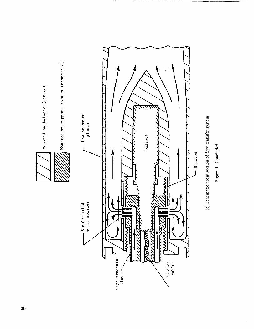
-,4
Ev
,'4
.0
0
'_
0
D
Et-o
E
o
o-
o
,ID0_xJ
Do_C
_=_
©
G_
o
O0
-6
©
2O

Airflow
path
Center of
pitch-flaprotation
",\ 20
Nozzle centerline " "" --. ,Z"_._.
20 °
1.17 °
5v,p = 0°
(forward-thrustmode)
5v, p = 19.53 °
(pitch thrust-vectored mode)
(a) Side view sketch of dry power baseline nozzles.
Figure 2. Nozzle geometry with one sidewall removed. Linear dimensions are in inches.
21

Sta, 41.13 Sta. 45.68
I r
xe 4.55
xt - 2.28 _ /'s"2.27
Th roat
ht - 1.09 I
I Nozzle
centerline
0.00 0.33
II
\
O.67 i.O0
Sidewall
h •1.18e
Variable sidewall length(yaw-flap hinge location)
(xs - xt)l_ s
2xs, in. (xs -xt)fl. s At , in Ae, in
4.55 1.00
3.79 .67
3.03 .33
2.28 0
4.33
4.41
4.42
4.40
4.72
2 Ae/A t
1.09
(b) Dry power nozzle with 6v,p = 0°.
Figure 2. Continued.
AR
3.70
3.64
3.63
3.64
22

Sta. 41.13 Sta.45.68
l_.___ xe - 4.55xt- 2.28 _-- < Is " 2.27
unvectored)
F / / /'_ .......... "i _F--Sidewall
I I
I _ 12"--,._i i - L®3
F / J_/ ]__...J Variable sidewall lenglh
//_--u.[--- --- 1 I ,-w-,,°"n_e'°ca"°°>
0.00 0. 33 0.67 I. 00 (xs - xt)//, s
xs, in. (xs-xt)/[ s At, in 2 Ae, in 2
4.984.55
3.79
3.03
2.28
1.00
.67
.33
0
3.91
3.92
3.91
3.91
Ae/A t
1.27
(c) Dry power nozzle with 6v,p
Figure 2. Continued.
AR
4.10
4. 10
4. 09
4.09
= 19.53 °.
23

Sta. 41.13 Sta. 45.68
xe - 4. 55 _ J
ht - 2.02 1
il'Nozzle centerline I I II I
s f _1 .
-0.03 0.31 0.66 1.00
II h - 2.60I e
' I
Sidewall
Variable sidewall length(yaw-flap hinge location)
(xs - xt)ll s
xs, in. (xs - xt)/l s
4.55 1.00
3.79 .66
3.03 .31
2.28 - .03
2At , in
8. 05
8.11
8.12
8.11
Ae, in 2 Ae/At
10. 40 1.29
AR
1.99
1.97
1.97
1.97
(d) A/B nozzle with _t,,p = 0°.
Figure 2. Continued.
24

Sta. 41.13 Sta. 45.68
I2.78
x - 4.55
eixt - 2.35 I _ {s : 2.20
(unvedored)
_ _ Sidewall
I, 0.74
I I I
Nozzle centerline
x _!s
/
/
i
/
I t II I I
II
II
-0.03 0.31 0.66 1.00
2.27
_L\-
Variablesidewall length(yaw-flap hinge location)
(xs - xt)II, s
xs, in.
4.55
3.79
3.03
2.28
(x s - xt)I/, s
1.00
.66
• 31
.03
At, in 2
7.97
7.98
7.99
8.00
Ae, in 2 Ae/A t
12.04 1.51
AR
2.01
2.01
2.00
2.00
(c) A/B nozzle with 6v,p = 20.26 °.
Figure 2. Concluded.
25

(xs - xt)fl, s
Upper and /lower flaps
0.00
Sidewall [ -.,-"
I1I
/Throat plane(unvectored)
IIiI
xt >
XS r
O.33 O.67 1. O0
I
I
-20_
f
f
f
Y
6v,y
Figure 3. Top view sketch of typical dry power configuration.
26

Airflow
path
r
r
x - 3.79S
7
x - 3. 03 ---------_-S
-2.28
I
J
Jj."
J
,//
.s
..J JJ J
J .."
jJ ".s
j flf'11 J
t"
I0.67 1.000.00 0. 33 Dry Ix)wer
(xs xt)fl's" -0.03 0.31 0.66 1.00 AIB power
Sta. 43. 41 44.17 44, 92 45.68
Figure 4. Top view sketch of yaw-flap hinge locations. Linear dimensions are in inches.
27

_ _ 0.7
._°
.Y,%
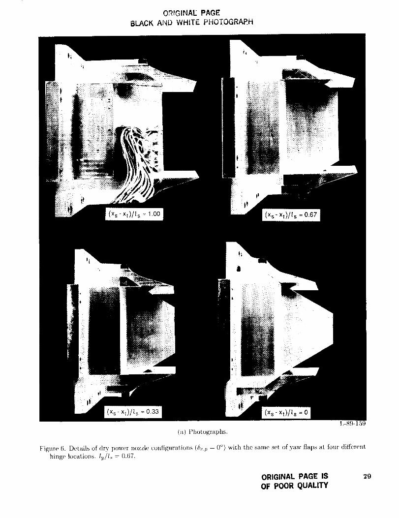
OR{GINAE PAGE
8LACK AND WHITE PHOTOGRAP.H
(×s-xt)//s = 1.00
tl
(Xs" xt)/I s = 0.67
i
(x s- xt)/l s = 0.33
(a) Photographs.
(Xs- xt)/ls = 0
L-89-15
Figure 6. Details of dry power nozzle configurations (_v,l) = 0°) with the same set of yaw flaps at four differenthinge locations, l u/l s = 0.67.
ORIGINAL PAGE IS
OF POOR QUALITY
29

F--L
(Xs- Xt)/f, s -_ 1.00
-k "-'L
(Xs" xt)/ls = 0.67
L
,7 j
--I_
(Xs" xt)/ls = 0.33
'-"L
..a-
(b) Sketches. 5z,p = 0°; a,,y = 0o; lv/l, = 0.67.
Figure 6. Concluded.
(Xs
30

OR',G!NAL PAGE
BLACK AND WHITE PHOTOGRAPH
ORIGINAL PAGE IS
OF POOR QUALITY
L-89-160
(a) (xs - xt)/Is = 0.67; ly/ls = 0.33.
Figure 7. Photographs of dry power nozzle configurations (6v,p = 0°) with different yaw-flap deflection anglesat a constant hinge location.
31

ORIGINAE PAGE
BLACK, AND WHITE PHOTOGRAPH
(b) (x_ - :rt)//_ : 0.33; lq/1, : 0.67.
Figure 7. Continued.
L-89-161
32

ORIGINAl: PAGE
BLACK AND WHITE PHOTOGRAPH
(e) (x_ - xt)/_._= 0; l;j/t._= 1.00.
Figure 7. Concluded.
L-89-162
33

34
r-e,_
'L'- ,,_:
!IO_I
o 'T,
,o'"
*: :', _ ;I :_. t*_ _:_!__ t_ :_i_-
'+.-,k-,. _4-;-kk:! _ ' --
O.
Z
" I'"-
? ± _, i--"- -
' .4_ _._,_-b_'.H_
± _,a42);:
!
Z
Z
I]
©
©=
©
©
o6

!;TT]_,rT,-H _
96 ..........
t_rtt_:
F .92 _+_++_i_Fi +'+_+++q:++++;+++:+++_
Fr 96 _
++
+ii_i+i++++;;_
+
++++-= . ++_,_
+++++++-++++++
++++++++++
+++++_ "+ + +u_,
+++I+++(NPR) d
LJtJ _;I
[IL+_:
!?;+_if+
_I:+++_=++.....'
*!i;_:itF :i;Mlii
,.+++ +,_P+tl-+L
_+ -+++:++
:Z+. +W!+_,,++....
k,ff'+,+_f_
_t+++ltZ: _L: +E+:]
.++, ++_,t+!1+_+1
8p, deg
24
2O
16
12
-++++_-, + .q¢+'+=j;
i,;!!i:.}tt_i]_F++/i_:' LU _+" ;;N';
.++++++: +U,+_:.,.- ,+ i ++l}P.i;+h]
Cd
1.oo _r+_+.++M++Ly++++++
+ :++++++_ ,+i_+ _+4
•92 ..............1
+++
3
By, deg
4
44+:4++_ ,++++4_-; 4+++-4,+++++_ +++_ ++ .,+H
I 3
....... _T _;;;++_!i++; 5 w: u:=+.... +,,, '_/,+ttt +`
+_1ff+ :
;t+%1;++_ _' H: h ._ _t;H:Ib
5 7
(b) Dry power _Sv,p= 19.53 °.
Figure 8. Continued.
NPR
35
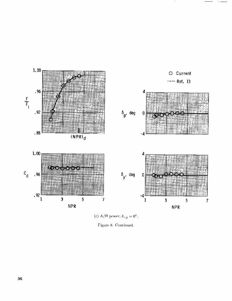
FF.
I
1.00
•96
• 92
• 88
..... _ m
(NPR) d
6p, deg 0
-4
0 Current
.... Ref. ].3
Cd
1.00
•96
.92
,,,.,,,,,_
;TIE-Fr-_R.
i!!!!!!!!i
:::::::::+
III_II1111
III_IIIN
1 3 5
NPR
!!!:_!"
ii!!iii
5y, degFm
.,m
7
(c) A/B power; b,,p = 0 °.
Figure 8. Continued.
l 3 5 7
NPR
36

I.O0
.96
F
F_ • 92I
• 88
.84
1. O0
Fr
F--_ • 96I
.92
!Reattached _liF_
. ¢. ,_4_l -]:n _!2f.
:f:ftHt+
t-t_rm .... ** _:tiW:4;
, i _p-: _+:tt
/- ;t q ;J
"i';' -'':d
:¢ ii:_t_ , ,' ....
......... ._. H./2 ! i [ t+ , **L;: :_ :I
I;ii[ : _!_!-_ii:[_ii: ;_:!r!ii,:u::: _:!z_[i_ !![]_qi
(NPR) d
6p, deg
24E:!ii!i:!
I;.. t ¢t141
',t :4H t::;
16 ..........1,4 i t4 F; _]
ii:££Zii
z2
4 .........
© Current
.... Ref. 10
Cd
NPR
(d) A/B power; _5_,p = 20.26 °.
Figure 8. Concluded.
......
1
•_++-_ t :: :1!1!7JIL-_ :::: : _ :;;.;;+_:¢4
÷_>;Mi .;s_Uj,5-++. -Hq r
'4 *--*+++_1-1-14++ ++_+* _+*+
NPR
_x _ _T_.! ttr_rtt T!',_4;tt4;I tl
H-tilt H_H _r r_t_
5
37

O
[]
<>
&
(XS
©
- xt)l[ s I-/[ s
1.00 0
• 67 .33
• 33 .67
0 1.00 F
Fi
i.O0-+-+-+-4-_--_÷
4_+4
-+-_++
96 -_• iiii+-+-4-+
Ji4ii
92f...._++s-
5 1 1. O0
Fr 96F. "
I
•92
4444
+++-_
,-_-+
Fr!!
-444-14 44-t4_4-_4
ii _ ill
IIIIIIJIl:llll
!! !!
/%
Cd
1.00 ......
• iiii
Ill',Iil;iil
92 _'_-
1 3 5 7
NPR
rr_
r_ Ir
(a) Dry power; 6v,p = 0°.
Figure 9. Effect of divergent flap cutout on nozzle internal performance characteristics for Sv,._ = 0°.
38

0 [] ©0
[]
0
(x s - xt}l[ s
1.00
.67
.33
0
{yfls
0
• 33
• 67
1.00
1.00
• 96
FF_ .92
I
• 88
.84
6p, deg
2,4
20
16
12
FTFE
_*tt
I;111
NPR
k_kH+H-H+H-H-H-I+fl
-_i i H ; ]fill <,_f!
_+÷+kH4+t+_ Hit
Fr
F.I
1.00
• 881 5
NPR
Cd
1.00 :_
• 96 I_i_
J_
.881
(b) Dry power; 6_,m = 19.53 °.
Figure 9. Continued.
7 9
39
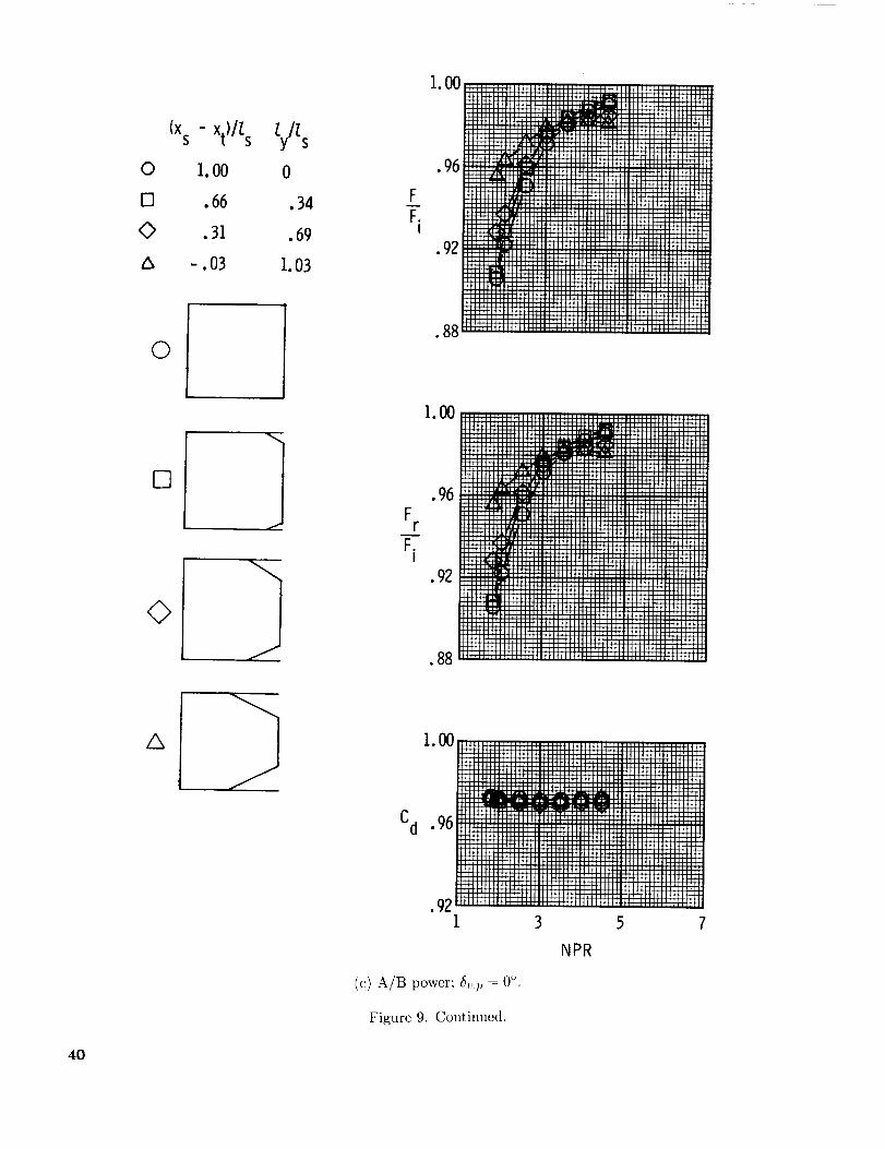
1.00
(xs - xt)/[ s Zy/_s
0 I.O0 0
E] .66 .34
0 .31 .69
Ix -. 03 I. 03
FF.
I
.96
• 92
0
[i]
0
]I
Fr
F.I
• 88
1.00
• 96
• 92
.88
z_ 1.00
Cd .96
•92i
(c) A/B power; _Sv,t,= 0°.
Figure 9. Continued.
3
NPR
40

[] 0(xs - xt)//, s 1.y/I.s
/x
0 I.O0 0
[] .66 .34
© .31 .69
/x -.03 I.03
I00
•96
F "92
I
• 8884
6p, deg
24
20
16
12
o96 ' T,, ,Jl,_, ,IL_,,,,,,,,_,_, ,, ,,L
Fr .92 .......;Li;'"'_I
•88
.Nl 3 5 7
NPR
4I 3
NPR
NPR
(d) A/B power; &,.p = 20.26 °.
Figure 9. Concluded.
41

].00
•96
FFi
.92
1.00
Fr . 96
•92
•8s
]. O0
Cd .96
.92 J3 5
NPR7
6V' y-'E3 0 I_'
"0 D -3C_
_
6p, deg .i
6y, deg
3 5 7 9NPR
(a) ly/l, = 0.33.
FigureandlO.(xsEffect_xt)/ls°f yaw-flap=1.00. deflection on internal performance characteristics of dry power nozzle for _v,p = 0°
42

1.00
FF.
I
©
[3
6V,y
0o
-30°
•88
6p, deg 0
I3
NPR
7 9
6y, deg -4
(b) ly/l,_ = 0.67.
Figure 10. Continued.
5
NPR
43

i.O0
•96
F-- .92F.
I
•88
.84
1. O0
•96F
r
•92
•88
1. O0
Cd .96
•921
":J]hd_i_ !
i!i_i::i.! _ _ii' '
i_!!i:!:! :i: r!ill
:11 il !_f;_:li:i ;iii_!i_:f!ililil',
: :-:__mx!i :!if! ;_!i]
i!ii_!]:!i:!'t _
h!i:iiif 'i_!:ili
:. ;i;it:]il,
"::"_V[._:v '/:'_ _,]_L: :.:: :: jr;il;::i:b, iitlh: ii:_i!i_ ::iL::q;: :,]
h_ !;q: t :¢.!',: b:_i:' F li !_; i _:i,:f!_!ii!i;i!i!ii!_#,_i!'!_i)_!L!ii!q!!!!!:!_ii
•! .!ffb;/,_(_iiL
_.r.<,_,ii_'i_i_...... :irLj_:
i: ',4r:!:m}:rv:
3 5
NPR
_P
7
fi_L:J_:-i_
;J'P,
tifF!!,
;r;r "
6p, deg
Y!f[:_i:i!i_t;:!i
9
6y, deg -4
JI
A
(c) lg/l_ = 1.00.
Figure 10, Concluded.
-8
-12
t aA4_t
........ kt
_thN .... :NN
.......... U:!tr;_
3
_liht,i
N
5
NPR
0
0
0
......... f .......
!l¢**i '-i" ;' _gT_
tl. tl_l:Tttl
7
6v,y
-2(P
-3_
44

6v°y
0
[] -21P
0 -30°
1.00 iiiiiii:,_:_::::_:_::_:_::. ,
6p,deg 0
_'i_i, _.
-_-..96
.92....._iiiiiii!!!_ii_iiiiiiiiiiiiii!il;!!!!iiiiiiiiiii:::":_:::: ..........
Cd
3 5 l 9
NPR
-12
I 3 5 7 9NPR
(a) l_/ls = 0.33.
Figure 11. Effect, of yaw-flap deflection on internal performance characteristics of dry power nozzle for 6_,,1_= 0 °
and (x,_ - xt)/l._ = 0.67.
45

FF.
I
1.oo
.96 _
Y
92 _• t_
W
88 _
u,
_D
.-O
5v,y
0 0o
D -30'
Fr
F.I
Cd
1.00
•92
•88
,00 i ,
1 3 5
NPR
+_-
llil[,
9
-12
-16
-20I
(b) [u/l._ = 0.67.
Figure ll. Continued.
5
NPR
i..... i '
I 9
46

FT.
I
1. O0
..... _ " i_!t
_÷i:.,,,,l,,_,,,,,_,_il/,ii:iiiii:iillllli__ , ,tHi !!!!!!!!!!!!!!!!!!_r_!!!!!!!!!]i'_i_''r': " _
:":""" U!iiiii', iii!!!!!! V,':,:,!!!!!'!!!!>_,_E_I _
• 84 II!!iiiiiii::_f:_:::i!iiii''i .............. i"!_:_:iii:::::::[_i_!"H"__J]
6p, deg
-4
I _ 6v' y0 0o
-{3 [] _30o-O
Fr
F.I
Gy,
-4
deg -8
Cd
i.O0
.96
•92
NPR
(c) l_/l._ = 1.00.
-12
-16
-2O
Figure 11. Concluded.
1 3 5 7
NPR
47

FT
Cd
F r
FI
100H_
iiii]iiiiiii!! _ iiiiiiiiii[!!!i]!!iil]]il!!iiiiiiiiiiiiiii!!![!ttt_
• i]_[[iii]!!!!iiiiiiii[[i][iiil--i_±iiiiiiiiiiiiii[iiiiiiii]_....... ::_::::::::[:!!!!:!!!!H!!iii_iiiiiiii_ii_-"£-!!il]]iii!!!!t_
• 92 ll[ll_l_l_:ll_lllIIlll]IIlJ:llll_lllll_ll_lJlll_
_HH:::H:H:H:;T:HI;::[H::::_HH:HHH::]:H::::[:;::HIIIII[_H:::I_
_iiiiii!!!!__'iW!!!!!iiiiiiiiiiiiiiiiiiiiiiiiiiiiiiiiiiil:::::::::::::::::::::::::::::::::::::::::::::::::::::::::::::::::
iiiii!!!_-_-_-_i!!!i_:_Li!!_iilWiiiiiiiiiiii!!!!!!!!
.96[iiiiiiiii[iiii[iii]i[iiiii!!!m!iiiiii_iiiii]ii_!_!!iiiiiiiiiiiiii
mmmmmmlld!iiiiiiiiiiiiiii!!!!iiiiiiiiiiiii!iiiiiiiiiiiiiiiiiiiiiiiiiiiiiiiiiiiiiiiiiiiiiiiiiiiiiiiiiiiii!!!!!!!!!iiiiiiiiiiiiiiiiiii_ ::'_
• %2 _iiiiiiiii_i]iiiii_i_iiiiii!!!!!iiiiiiii_i_iiiiiii!!!!!!!!!!iiilliiii_
_!_!!!!!!!!!_iii][!!_!!]_H_[_!!!!!_!!!!!_[_]_][iiii!!!!!ii_
:::::::::::::::::::::::: :::::::::::::::::::::::::::::::::::::::::::
_iiiiii[iii!iiiiiiiii!]![!!iiiiiiiii_ii!![iiiiiiii!!!!!!!!!!_!!]iiiiiiiiiiii_l
.96 ....._:::mliiiii_,__H!!!!!_-_:_`-_:_`2_:_L.!!_!:_:::!_}5!_:_JE_i!!!!_H_]H::]_]:.,_ ..... _-_::-_,_''"[H:Hff_':::::::.,--_:::::::::H::_[H_I]_H]H|::::::::::::::::::::::::::::::::::::::::::::::::::::::::::::::::::::::::::::::::::::::::::::::::::::::::::::::::::::::::::::::::::::::::::::::::::::: ....... F
.92immmm_m_immmmmm_mmm@iii_i__I 3 5 7 9
5y, deg
_Sv,y0 0o
_0 _30o-/ -.O 0
......................................
!iiiiiii!!!!iiiiiiiiiiiiiiilWiiiiiiiiiiiiiii_iii_m_m*t:::::::::::::::::::::::::::::::::::::::::::::::::::::::::::::::::::::
iiiiiiiiiiiiiiiiiiiiii !iiiiiiiiiiiiiiiiiiiiiiii!iiiiiiill...........iiiiii!!iii!!!iiiiiiiiiiiiiiiiiiiiiii!!!iiiiiiiiiiilNiiiiiiiiiiiiiiiiiii
I]IH::: _ H:H:IIII:::[:::iII:II::::::IIIIHIIIIII:i:iiIIIIItilITI
iiii_i__!!!_iii___i___Niiiiiiii_____iiiiiiiiiiiiiii_iiiiiiiiiiiiiiii_i____i_i__i:_:HHlltlllllHHllllllHHII_HHH
|IlIHIlllIlIHIlI_I|IIIjl:IllllIlIIlI;IllllI_llHllHI:II I +_._
-4 _ ii[]ii!!iiiiiii_il]iiiiiiiiiilh::ilil...................... J:::::::[:::::;:; ............................. ] -
::::::::::::::::::::::::::::::::::::::::::::::::::::::::::: ;_J
i]]i[iiiii_iii!;iiii_iiiiiiiiiiiiiiiil]i_iiiiii! "_r,H'ftt_'_:::]:_H::::Ht:H:T:H:::J]:::I]]_ii:::i_iI::HH÷H+H_-_I_÷+_
........... ::;:H::I:I:::::Hi::::H_]H:_;_H::II" HHH+_HH+H_H!_4_'
:IIHIHIHH:_!!!II_IHI:]IHIH::HIHHI:IH::I:]HlY_+_::::::::::::::::::::::iiiii]iiii!!]!!!!!!!!!iiiiiiili¢l_l__
-8 i iiiii iiiiiiiiiiiiiiiiiiiiii!!!iiiii!!!iiii
i]]!!!!!!]!iiilHITi_i;iiiiiiii]i:u::::::::::::::::::::un+_+n-n_ • .
__2iiiiiiiiiiiii!ii!ii_miiiiiiiiiiiiiiiiiiil]i]i_!_1 3 5 7 9
NPR NPR
(a) lu/ls = 0.33.
Figure 12. Effect. of yaw-flap deflection on internal performance characteristics of dry power nozzle for 6,,,p = 0°and (:cs - xt)/ls = 0.33.
48

1.00
.96
FF.
I
.92
ou o 0o[] -2O>
-00 -30°
_r i;.,!_.!i iiiiill ii_++i44_iiiiiiiiiill ii_![_+ •illi .......................... filial .... ',l",i,,,_
_d444N i i i i i H l ] l I [Ii __,_tffl-P+ fi4_ I-'H_ _ i i i i i i l '_I I I l I I [ I I I I I I I I l l'_ i i i " "]_l"1 .......... m' I I ' I ' ' 14 --
7,[_ i u i ,, i] ! I ,, I_ _' H I-, H4_+,u4+m _
8p,
+ ,i i _ i,<]II [ [, H 111, H I _H4" *
+ + 411 '_l '<', i I ! I ',_I_I I ', [i '_<.I ',I I l [ i _ ............... i,, ! .....
deg --,
1 3 5 7 9
NPR
1.00
F.96
F.I
•92 -4
Cd
NPR
5y,deg -8
-12
-16
-20
(b) l._/l_ = 0.67.
Figure 12. Continued.
1 3 5 7 9
NPR
49

F
F.I
|HIIIII_ LH I_ :.--"P,_",_F'--I_,"I"I"_iillIII|fillH IIIIIlIIIH IllIH IIIIIIIIIiIIIIIII
":i_i;ii_---qTFiiiiiiiFi_'_-_:::::x:i:::x::::im_:m::im::m::p:_ ........ H, :,, H H ], H+HNkH-FPg_'_ H _H H+HH+kH_I H _ H+_H+H4+kH-_
................ : H _: H t+HH_,f'i"i_ ....... :H! ...... ! ............... I
.......................... _,,,H-HJ................ ,,H,, ............. IIII_'_A4.LILI.Id_:[IIHIIhlHHHI
9 A l_ ........................................................................• " __iiiiiiiiiiiiiiiiiiiiiiiiiiiii_'iiii!!!!!!!iiiiiiii
IJd3_I_IIIMII::I:IIIII:IIII:I:HII:I:HIIHIIII_H-I._I+H4441A+_ ............... IIIHIIIIIIHHIHIfIMIIIUIIIIIIIMIIIIHIIIIIIII
IIIIIHII:IIIIIIIHHIIIIIIIIIH[IIII:I[IIIIII:IIIIIIIII:::II:::IIIII
_,+iiiiiilIiiiii_._mmm::m!!!!!!!!!ii[_iiliiiiiiiiliiiiilh:_:t_I-H_ .............. _"I""_'I"]II:::::[::::II[|::II_:;:I:HIIIIII)I
I_t-r'HM ..................................................... ,, ................
:HHHH'"H:;IH::;I:H:::::::I::::I:::::H::;;:H;;;::H_IIHHHHIHHIIIJ:I_H&FF,t_It+I_IIIIIIIIIII ............................................................................... mmHm_:::::m::::m::::mmHmm_m:__t_:::--j'_!!!!!!!!!!!!_i__!!!!!!!!!iiiiiiiiH"`h_.._H!!_.-.'_!__i_N!!!!!!_H_IIH!H-H-INH-III::II'-'-'-'I_II_IIIIIIII;IIIIIIIHIIIIHII:I:IIIIIIHIIIIIIIIIIII
[_iiiiiiiiiiiiiiiiiii_g_Jiiiiiiiiiiiiiil]iiiiiiiiiiiiiiiiiii]iiiiih_IIHIIIIII|I_IIIIII_III_I_IIIIIII:'_'_I_H_IHII_IIII_IIIIII_I_I_II_
_tI_:_H_H_H_-_P_'_-_z_::::::::_I;I_I;_I_IIIIII• _H'+IHIIH:IIIHIIIIIIHIIIIHI:I:HI:II:I::IIIIIIIIIIH;IIIIIIIIIIIII:I'"_IIIIT:IHIHIIIIHHIIIII:IIIHIIII:I:IIIh"_dI:IHIIIIIIIIIIIIIIIIIIIIMII
I_iiiiiiiiiiiii_iiiiiiiiiiiiiiiiiiiiiiiiiiiiiiiiiiiiiiiiiiiiiJiiii!!!!!!!!!!H_-H'I:IJlIHHIHIIIIIIIIIIHII:IIIIIIIIH[IIIIIII::II:IH_IIIIHIIIIII[II_H[|
,:...........i_ilII:IH::IIIIIIH:I:H:IIIIUIIII:III:II:IHIIIII:HIHIHIIIIIII
_'H_H'H+'fH-H_HH-H_'+_+HHH,.IIIHHIIIHIII]III|]III+H+FI_N-H_
8v'y0 0°
t0
-0 [] -3(?
41_qG_i_I_iiiiiiiiiiiiiii!i!!!iiiiiiiiiiiiiiii!H!!M![[!!!![_
I_T_!_!i_iiiilliiiiiiiiiiiiiiiiiiiiiiiiiiiiii!!!iiiiiiijjiiii!!!!!!!!!
__iiiiiii[il!!!!]!!!]!!]!iiiiil]_iiiiiiiii_ii!!]!![]!![![[!]_ll
0_i!!!iiiiiiiiiiiiiiii_E_i_i;iiiii:#_iiiiii2g_iiil][iiiiiiiiiiii!IH-I+I[I.,':_"=_.'_,d.._..I,_.,'_..I_..=_.I,,_.%_,.HIIIIIHII:IIHIIIIIIIMHII:I-H+H-fHerl_ Ir_P_h,'_fH 11111 _I I i I : : _4._i ;i H i;_,] I I I II I U: I :I I I I I I I: i i i i i H i.LI
......................... Ilk ............. HHIHIIIIIIIHIII ...... III'"I[:lll]ililili...................HHII+HHfH_H-I-_fH&IH_IIHIHIII:HIIIII:IIIIIIIIIHIII:IIHIIIIIHII:""
• ,_ii_4_i4_,_,._ ..... :::mi_:_miiiiiiiiii_i!!!!!!!!!!!!iiiiiiim:-4 _+,+___41_+_+m_+4m
1.00
Fr .96F.
I
•92
_HH-_ _HHI]IIIIIHHIIIIIIIIIII!_iilH:£-_:_T-_:?_i::_:ililliiiiiiii_lii!!!!!!,,_,,_!
_LIz_!_HHIHIIHI:II!IIHIIh"_:_IIIIIIlIIIIIIIIIIIIIIIIIIIIIII_'"! 'If
|_11111H ];H _,_.,_,_.i;;,'i'i_"?;.,_N ;:;:[IH-H :H illii;ii;;;;H __i_.._IllIII_IIIIIH :I_:
_:i::iiii[iiilHiHiiiiiiil:._:i_i_iiiiiiiiiiiiiiiiii_iiiiiiilliiiiiiiiiU_z_H_Hi_I_H_H_'._._H``_2_'AH`_'_`_I_:_I_H_H_I_I-H-_IHIIIIIIII:IIIIIIIIIIIIIHIIIIIII:HIII:,_4IIIIIHIIIIIIIIIIIIIIIIIIIIIII
FIIIIHIIll]IIIII]IIIIIIIIIIIII_HIIIIIIIlIIIIIIIIIIIII[IIIIIIIIIIIIII|!i]]HIIII)II:I]IIIIIIH+HI]I ...........
1.00
By,deg
Cd .92
5O
.841 3 5 7
NPR
-249
(c) ly/l_ = 1.00.
Figure 12. Concluded.
1 3 5 7 9
NPR
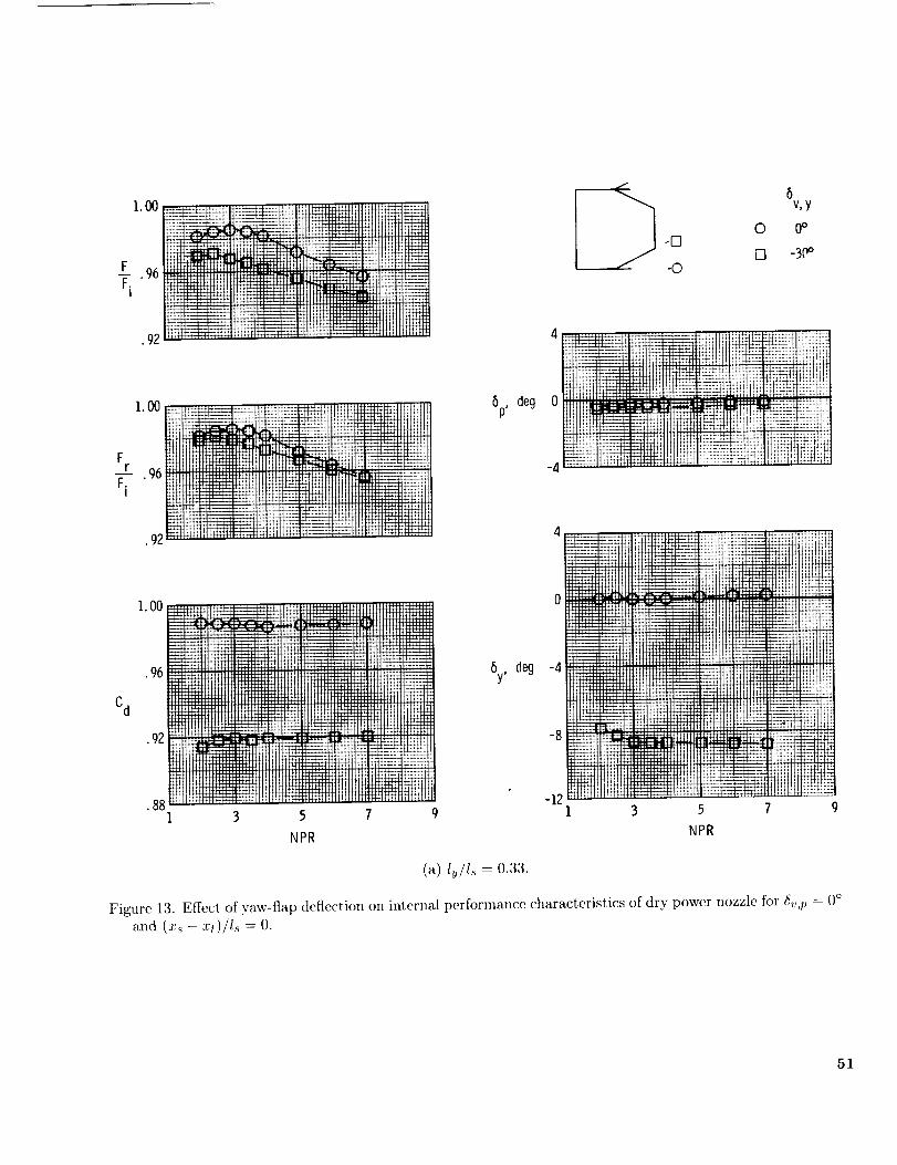
.92 _
Fr _.
Fi
N_
..... Lbl H ,_
NN4_,_N B444!
1.00 _ ,_,+,,,
..... Hill
+._ iiiii
•%_ _c_ _.92 _ ,_,__,_-_
88 m_1 3
NPR
JL '_
HU
t:t:Lt _1:$4-
t t_ tt!nff_
, i
7 9
5p,deg
By, deg -4
._ 6%Y0
-D[] -3_
-0
4 _ _ _:_t_.._i_tL__4_ _}_.;_;
....... . +. Ht.L
N NNNNN
5 7
NPR
?#;2!
NN
9
(a) l_/l_ = 0.33.
Figure 13. Effect, of yaw-flap deflection on internal performance characteristics of dry power nozzle for 6_,,p = 0°and (_'._ - .rt)/I._ = O.
51

t. O0 _• ,_....
r .96 ; _'_'_
Fi "_I': ......
_Lf : LLm&_
•92 _ ....... HI [_;_I _,_ _
Cd
1. O0.... ,.............
............. u'_l',:::::iiii]!
H_Ngt4__
•92 _
•88 _
_ ,%'I:1:I[ ......
.N 1......... _m_r3..............
'f÷_l!
iiiiii ........ 2
44* _ "
N'7
NPR
] % -
I?i!5, deg
44 t
o!_i__!!_,_; ..........
@
;G :;;;
±ftJffr_.
-4
5y, deg -8
-12
-16
-2O
(b) lv/Is = 0.67.
Figure 13. Continued.
4
'_ '4;141.
,
!
J
7H!_
NN
_rrrr
N
N_
3
tO
-O
8v,y
0 0°
[:3 -30°
5 7
NPR
52

1.00
.96
F-- .92
F1
i
• 88
.84
......_ iii
l!iiiiiH
i_iiiii
:Mt_.:t
<
I_ili!iil
_*i*:_iiiii![!i
!!!ili!i_lii_!l!i*iiililiil_ii!iII!i
! _i!!iiiiii! H
!i !i!i[i!i!,!i
©2_
-0
6v,y
0 0_
[] -20°
© -3oo
4
6p, deg 0
-41
_._ ..4.,
3 5 ?
NPR
1.00 .......... ilit ?
IIIIl!i_i_LI
Fr .96
..............iiltiti!itiifttg_.92 ............_Ht!Hiil[t)lii!ii
1.00 .............
.96 ..........
TT!!!'_!_TTTT'
'!IHFCd .921!!!_ !i!ii
,IIIIII_IIIIII
i
1 3 5
NPR
t_iH ....M: :%_
V;
t*t_
::i! ....
i!! .....t,-,_
!!!!_!i!!'!i_
...... iil _,:Hl::_tt , t_!
_:U:;Mt :_tt:11:
Mgrt_ M:
iiiiiiii i!iiii:..... _!_!i!_
...... ;U_ [!:
9
5y, deg
4
(c) Iv/ls = 1.00.
Figure 13. Concluded.
5 7
NPR
Illl+_+÷-
++++
H,i:
_ittl]T,q
53
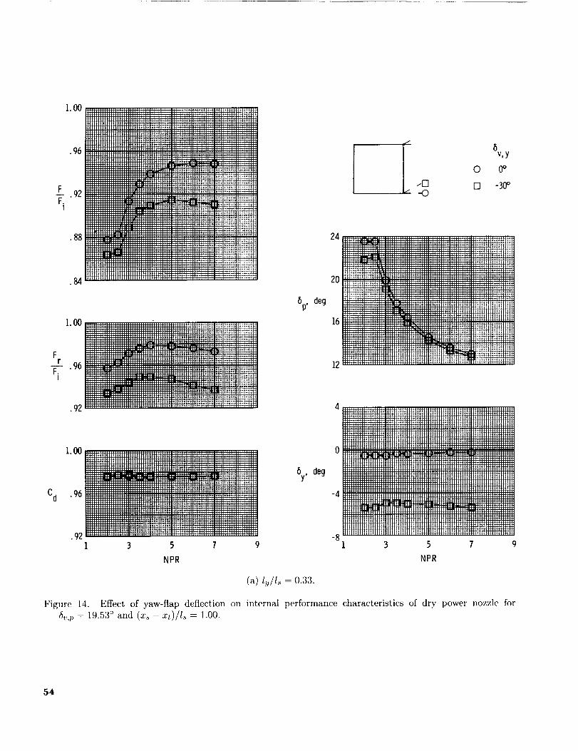
l.OO
_.F . 92Fi
"; ;H;H;;HHH;H:HIHHH;;HHH:;:: _ _+H-H_F_H+IH_fffHI-H-fH F_H| .................................... _E,: ...........,, ; ...................................... ; .......... ;, HI+PHI+HH++HH H
_iii[iiiiiiiiiiiiiiiiiiiiiJH__
iiiiiiiilliiiiliWiiiiiEiiiiiiiiiilHHEiiiiilWHiiiiiilEiiiiiiiiiiiiiiiiiill:HHHHHIHHHH:HHHHHNHH;H|HHHHHHHH:H:H:_'_H-kH-h_H+I
iii[[[I[I[[[[[I[[U[[[[[HII[[_HIU![![[[[[HHH[[[IIHH[[!!U[!!H[HIIHH[I.96 _![[!!![[[[![!!}!!!1_[[![[![![![[![[[[[[[![![![[[[[[!!!![!!!_!![[!!!![[[[!!!![![!
::::::::::::::::::::: i:-_ [ :::w::::::::;:::;:....... H:::HH:H:! ...................................... H-FH4H_FFH-PFFFH
[;_[;_:H:::::N:H:::_H::::::HHHH:HH::HH::HH:::::HHHH::HH_H-H
"iiiii!!!!!!!!!!ii_Ei!iiii_H_,_H_!._211Wi_iilHiH_[ii[[i[ii[i[iiiiii_H::::::::_[iiNHiiiii_i_i_Hilt_jilj;;[[![[[[HHL'-':[[[F:_=HHH[HH!_HHH[[HHHH[[[[I[[[HH!H[!;![4441.,H::HH:H[H:_[::_[;:H::H]H:::::H;;;H;::]HH::::[H::H:H:HH[H]:
II[H;;[;;;_[H::_[]:_::HH::II[::::H:IHHH][::::::I::I::II:]IHHHHHH]:::[:H[::HI[[I[_H:::H[[][:::H:::::]g[::HH][H:[:H::I:H::[:HH:HH[H::
• 88 ::::::::::::::::::::::::::::::::::::::::::::::::::::::::::::::::::::::::::::ii[[!!!!=:__'?iN_i_iiiiiiiiiiiiiiiiiiiiiiiiiiiiiiiiiiiiii{iiiiiiiiiiiiiiiiH[i[
EH[[HH[[H[:"'[[[HH[HHH[[[HH![[[[HH[[[[!H!HH[[[HHH[H[H_
!H[[H!!_,_'TH_H[[HH[H[[!!![![![![[![[[![H[[!HIH[[[!![[[!!!![:,_,r_ ii[iiiiiiiiiiiiiiiiiiiiiiiiiiiiii g _iiiiiiiiii_iiiiiiiiiiiiiii[iiii[i m .................... i_-_-_+*_
6p,deg
Fr . 96F.
I
24
I Ov,y0 0o
..FI [3 -3O°--0
12
• 92 4
i. 00 0[[[[[[][[![[[FH[[[_[H[[[H[[WHH[[[H[HHHHHHHH[[[[[H[[[[[[[[H[[[[iiiiii[i[illiiiiiii[iiiiiiiiiiiiiiiiiiii[illiiiiiiiiiii!!!_IiliI[[[_'_-_'T'F:_.L!![!_._H!!_!_H]H[HH[[HH[[iiiiiiiiiiiHiiiii[I_[I[[HHHH[[H[[I[I[[[HHIH[[H[[[[[[H[[H[[HH[H[[[[
Cd .96::::::::::::::::::::::::::::::::::::::::::::::::::::::::::::::::::::::::::::::::: -4!!!!!!iilllllllliiiiiiiiiiiillilillllliiiiiiiiiiiiiiiiiiiiiiillllliiiiii_
:::::::::::::::::::::::::::::::::::::::::::::::::::::::::::::::::::::::::::::::::
IIIlt
1.O0
•96
__F .92F.
I
• 88
.84
!iii!ii!;
!ii! _t!;IF:-" 1-
I:;L_ii!!i !!;
i_.'_F"
Fr
F.I
1.O0
•96
.92
•88
_.: ii
;ii!_ii,ii
Cd
1.O0 _ _ ,rZ_.; ,_H_-_
• 96 ;II_1;'] !._ ........ !,!:,! :
1 3
;t': !}':i: :i[
"i!]]iF_
5
NPR
:m:m. I{=4-;_,_:
....... l 12_212;72
........ **_÷+.÷+
7
6p, deg
6y, deg
4
0 _
. _1tttllffff
I 3
.-[3
-43
NPR
0
[]
®
6v,y
0o
-30°
4_44 _
N
N
@
55

FF.
Fr
F.I
Cd
1. O0 _ ,_.
.96!!_;_L!n_!
_!ti!ik
•92 ....
.88__?ttrt
_ i .
,00 ....... .......
,96 ...... '_
.92 N
• 88 .......
÷_.,-
G_
t:m_m
g_t;t_S_St_
I. 00
,96
•92
_i ......_4f4i........
.N421
ii!i!_ :! !_ '_:_ .........• "_ _Ft_ ............. _._
3 5 l 0
NPR
6p,deg
6y, deg
24
20
16
12
-zl
-8
-12
;:;;;:
51n_t_
!!''l[!
l
I©
0
[3
0
6v,y
0_
-20°
-3&
CT; , L
:f_Ei<
_¢_ :,_ .,._:._._
_:_rr ;;;[,:]::?}':l:
'_',_I_ [', ................
÷÷_
3
NPR
(c) 1SI_ : l.O0.
Figure 14. Concluded.
56

0
[]
<>1.00 24
•96
__F.92F.t
•88
bv,y
-- O -20°
-30°
6p, deg
ii Ji!<iii:__ 7-:--=I-÷_- l= ._..f:_<_ f_/
_,::: , T _i !: !_; :f_::iti-:ili,!Ti_i.:ii
2O
16
12
.84 8
1.00
Fr
F-'T.96I
•92 0
ii! ilia:,_'/iili i i!T7
<:i::4. .!i,: .! : :i'!
_i(/i!i!:!<:,
6y, deg -4_!iitili!i;ii!
.92 :!;{;{t{t ii!!_/i1 3 5 ?
-12
:: i,ili_T,'_: _i! ::],!_H!i]{'-t!h!! !!ir!_:i I _iit_R]iC
::_ _ '_c. _! !!ii!i _:m.}:""_:::;- !{';_ii i:_i_{i:i L:i!iEi
!_i_!Ei__:_*
;f! i", :;,.-i,:{ _.._,, ,_ .., .,., ._;_,
3 5 7 9
NPR NPR
(a) l._/l_ = 0.33.
Figure 15. Effect of yaw-flap deflection on internal performance characteristics of dr.,,, power nozzle for(_',t, = 19"53° and (xs - x_)/l_ = 0.67.
57

_ 6v'Y0 0°
I .-I-3
I . --o _ -3°°
24
20
LFi
.00 _ _ ...................................... "
|I ............................................... H-H+.N, _II[]_HH_:_HIIIHI|II;HIH::_HHH_IIHHHIIIHH[:H,.,.,,,.H_ Hi ........................................................................... :HHHH[H:_HHII:I[H:HJH"UIHh.,,IIIHJ,III
•96 iiiii!!!!!!!!iiiiiiiiiiiiiiiiiiiiiiiiiii_iiiiiiiiiiiiiiiiii__II .......................................... I
I]HH_;HHI_JHJ[IIH _,'T'-I';.'T;:HHH_:HHH_'PH-H-_ ......... ill ........
ItHHIII_IlllH]HllHZI:IIIilllHllHIIlIIIIlIHli[HIIIIHIHH_%_+_
• l_;iil;i;;:;;;_;;i_i_ii;ii;;iIIIIIIIII:IIIIII1_illi_H_[[[[IH!![_[_-'"_:::::_F__":!!_:::ii: ..........liiiiiii_iH!!i:_i!,'."_?jiiiiii,_iT:,'iiiiff
I :-.---_-'_,_ _:_HHHi::HHHH_::HHHIIIIIIHHHIIIHI ..............
iiiiiiiiiigiiiiiiiiiiiiiiiiiiiiiiiiiiiiiiiiii!!!{!!ii{igiiiii_i_• i iiii{_iiiiF{iiiiiiiiiiiii{!iii{ii{iiiifiiii;A-i4...................
I [ :H_:IiIIHII:_IIIH:HI:HIIIHIIIiIIHIIHII_+H- _
iEHi{ii[_i{[i[f_{i_{{_[{!H!![!![!{]_i_[[!!!![[[__II:IH_:H[H:HI[f]IHHHH]_
I[[H:[HH:,:IHIHI-FH-F___
141_III_I[IlIHI_IIIIUH
6p, deg
16
12
1.ooliiiiiiiii]iiii)iiiiiiiii_!!!!!ii_iiiiiiiiii:: '
Fr .96 iiii}!}!__:,:.:_iiiii_iiiiiiii[iiii::_.___ !i{iiiii_%_iiiii!iiiiiiiiiiii!!iiiiiiiiiiii_-__
iltlt;;;;;;_;[H;H:::HHHH_:[H::::/H[H]_:f:HH-H_'_H r .
iiiii[i[[Hiii[_iiillii_}]Hii_ii[iiiiH_ii[[[i[iii[ _÷_
5y, deg
-4
-8
Cd
1.oo_
.96
.92 _
1
NPR
-12
-16
-205
NPR
N
®N
58

.00 ....
.96 _i!li_
F .92 _:i:_r_
Fi f!_!_-=Jrtt:tf_tl
•s8 _
.8_ .....
1.oo
Fr 96 _i_Fi
.92 _}_
1. O0
Cd . 96
• 92
!ii E: lii
F ;'
;:'dYF:
-E3
-0
;tiHTH?
i$iHL_
i,_ i-r
NPR
0
[]
_l [ ' _ l _ _ ] _I _l l
I i! i;_'i}1!_
it
_._ii_i!]_ .
6v,y
0o
-30 °
24
2O
t,_tt_
L;X
8p, deg
16
12
6y, deg
-4
-8
-12
-16
-201
(c) 1_/1_= _.oo.
Figure 15. Conchtded.
5
NPR
;.t ;_HI
,t_ttt ?t
_dTTTT'T
_INEt
_±_rrH
N
_E
$[i: :ll 1
t[h:v-tu+,+,_.W'4_
stt:ft_N
9
59

FF.
1o00
•92 i_m_r_-mm___,_
. ,_ ' _ z
•88 !iii,I_N_,
1.O0
Fr
F--_.96I
•92
ii:,_!L,
!ti.........fl q ':_
1.oo
Cd .96
.92
__/_!ti!_i!_ ili_ff__
' ' . i} " t i _iiihi
3 5 7 9
NPR
5p, deg
16
5y, deg -4
-8
-12
24, H
12
_qi;;41&
*'TV%
t_frt_ll
:i% i_
-O
©
D
6v,y
0 o
-30°
5 7 9
NPR
(a) l_j/I.s = 0.33.
Figure 16. Effect of yaw-flap deflection on internal performance characteristics of dry power nozzle for
6:,,p = 19.53 ° and (:rs - :rt)/Is = 0.33.
6O

fJ
.... " \L_'._. _ '_:,'
•,(:." '.=_':'L:
C_ _,.
• _ _

6v,y
0 0o--F3
[] -30°-0
1.00 , ,_. .... ,,
F 92T, N
6p, deg
62
1.00
F_r .96F.
I
.92
-4
-8
Cd
88
1 3 5 7 9
NPR
6y, deg
-12
-16
-2O
-241
(c) l,_/ls = 1.00.
Figure 16. Concluded.
5
NPR
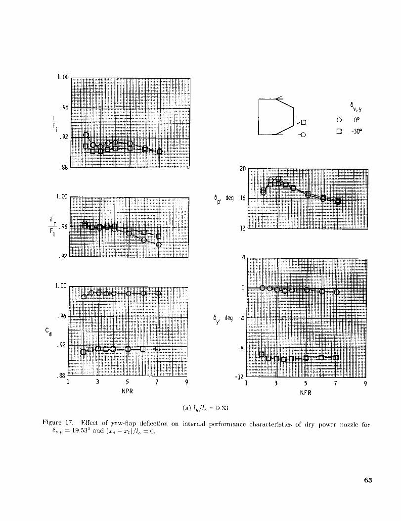
1.O0
•96
F
F.I
• 92
• 88
ALJCJ "ii::!i ......
FF_ :;;==;"
,tt_N ,-_.**
1.00
Fr 96Fo "
I
•92
Cd
1.00 :?_i?;_,_;:!_....,:_.........._.
.............. _];2! _: t t:
1 3 5 7
NPR
.... H+,;,_.I'I
I'.I[r i
tt:_tr'_ ;FZ[F;]C-
V?ttr_H
....... ii!:iii_i
I_ _.....i-::t
¢!:_T;IiHiii:i:,,,_
_p, deg
6y, deg
C 6v, y_0 0 0°
--O F1 -30 o
I;_:¢T;
12 ;;Hm :_.t,,
4 ...... ii!iilil liIL_
: t_: _%+,:l ::¢$_t¢t
.........! ;
3
I_4HflH
5 7
NPR
¢ttCd__Jmtt_
4tt.H4__/qq
H U, H '.
. ,qlttl
9
(a) lu/ls = 0.33.
Figure 17. Effect of yaw-flap deflection on internal performance characteristics of dry power nozzle for6_,p = 19.53 ° and (x.s -xt)/Is = O.
63

1.ooi iiiiiiiiiiiiilNiiiiiiiiiiiiiiiiiiiiiiiiiiiiiimiiiiii iiiiiiiiiiii iiiiiiiiiiiiiiiiiiii
i iiiiiiiiiii_i NIIIi41IIIIIII',N
IiiiiiiNi' iNIHINIIH!!! IN!HIIIIHIIINi '
-fi ti ......... ;LL,+;.......__l-#l i I '_: l: [ , , H I [ I ',: H i 14-I-F
(I HII:',IIIIII HIFHi
iiiiilNi
IIIN!!!I4-tltHlil
HHIIIII
H HH_
1.00 __:i _ ..-:!!!!!!!_.-!!!!!!_:' iiiil 17÷.,__ :'.m', :m '. .... _ ...... - ......_,,_F'_'.!! HH,,iil HH'H'IIi'!'!"H i'll '.'_
_HI'H__.','":'.:H,,,IH EHH,',N_'HN'"HIlIiiill _ii'-t_"_
1 _11[111 ......... ,, r • i zirft;_ _1
i!!!!!ll!!!llll]i: iiili tIllli!!!!iiiiii:Nii_!!!!!iilNiiii__111 ;....; ...<..,,.,.,::.,,.:,.,,,_,.<,,,:,..._...._..,.,.:,.,._:,II ,,1:1i_l ,,: ,,: :, ,,H :::: : l_i+_ +h-ri_ i_m)_m_im_:diiiiii::i::i::i::,i::,:ii,:ii_,':ii'_
I ,lllll''"Hll[lll:l:lll•88 m..................... _+_ _
.84I 3 5 l
NPR
'_ 8v,yt [3 0 0°
-"(3 [] -30°
6p, deg
lll::IIH-IIH::HH:
:::I:
:,,i,
20
ii _,4.'_ i i-._''< * +_+ i?l+,,
............. I H ,_'t4@_ :_:_+71:_£H +.
-4
By, deg -8
-12
-16
(b) ISls = 0.67.
-201 3 5 7
NPR
Figure 17. Continued.
64
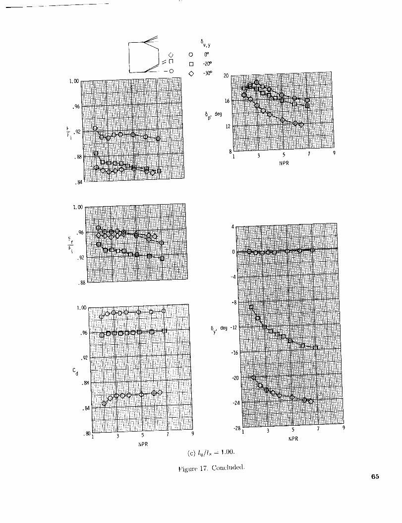
I "',I '<'>I
-0
'iii'i!_i_Li,-ii<'"_ _ 'iii_'ill_'-_'_":_......_•96 iii!ii!i!!i !I!Ii!!i!!i_,+iiiI!!i{!_I_+F:{+!!iI_F_!i!+iuiii:...... _,T,,,;:......... ....... i?,?_!
:: : .... ::i: : t_:_._._:
;:,; : :: :: :: ; : ; ; : :
==:===!!_ _ _ b;t!_!ii!iii!iilliiI!iil!_+::_'._
'" _' 'fi!l!i !,F_i_.
0
E3
o
v,y
0o
-20_
-30_
6p, deg
NPR
Fr
F.I
Cd
I. O0
.96
.g2
•88
1.00
.96
.gz!
• 88
.84
.80
!'I!+!!! ! :: ::': ;:: :: :'.i,+_it_'il_lf÷_if÷_ !_}_z_gt 11!1.
,4 ,:,, :,, ...... , +,_+_, ....................... )+,+, H_
::' ::':: ,; ,, ._ _,_ _ttt_ II+, _;l!?!i; t¢it:$_';)
..... ,........ ,, ..... _!!!!_!.................
H;,HH :::: : ............IN _ _'++'++" "+'+_"+............. _i ;_I_:_._ v+_++_ _ _::It:
4_!q+_1 !lff_I+
i :F:i "+;LI_1 t F:m :!I- ?, !t,tt _(:.;_tql d+_¢_iiIt t r "?t_tt + ...................
............. ++.++.++_........ : : : : :
..............i .......
deg -12 "_"+_' -";_' _ ....... ......
....... *+_'_+_++ -,,;..;++iZ t;tt_H:I
............ + _++s++
E_T_-As 4;_,_i _ i _ .................
-24 _tNt! t_'tt-',_-tt-_t_t ....... ' -' '............... _+"_" '¢'-_+d-'J
-28 1 3 5 7 9
.......... : .......... H!i!ii_ !ii{Ei!
:.,,_:_...... _t;:_iiiiiiiiil;ii!iiilili!!ii!i?ili!ii
i!!i!!di:ii!ii!ii ihiii_i ii_!i_ }ii!lit!il
..................._t: t.j _Si!i;}!iii?!iii!! :' .....
ii!iii!', ., _ii;_i:_] ;!,:dhh:ihH_::H:ii!:i t;; ;1!; ;:':iHi ii!ii!!il
ii'!sifii!_@il:_iii;!}iiii;tli!}iii';iii_?tllillii!_i_itZ_!_ii!F,t,m;_4!;_;_;m<:_'::: "'::" !}tl:ii!!iiiiii}..... i!!_i?'Ii;i!!_i_::ii;mi:::_!iiflifflii!:ii!ii.........!i:[!iig!:;i'iii!_
12,:H?? _ii!!i]! _::':::................ ::_':I:: H!i_!_il
3 5 1 9
NPR
(c) (_/I., = ].oo.
NPR
Figure 17. Concluded.
65

Cd
1.00
"96 t
F .92Fi
•88
.8,1
._ _iit=2_
Fr . 92 '_
.88 _
slE
¢_!i_ ]:_!F{r_i' !_'_J'F'_ i
T!!i! ihT ,i"_[i-__
i" L1 " 4 _ ,
_r'T [ .,f!
+. ; r+.;_t_ ,
I"°°i• _ _ _
"ii1 3 5 7
NPR
5v,y
0 0_
-30_
6p, deg
i_,+-I!-*.I
o;;;;;t$i,_
o_
4
,_WI
-12 _NN
1
]
_'TT:
J []
I -o
NPR
Figure6v,p=18"0° EffeCt(x.s- Ofxt)/&yaw-flap=1.00deflecti°nandly/l_°n= 1.03.internalperformance characteristics of A/B power nozzle for
66
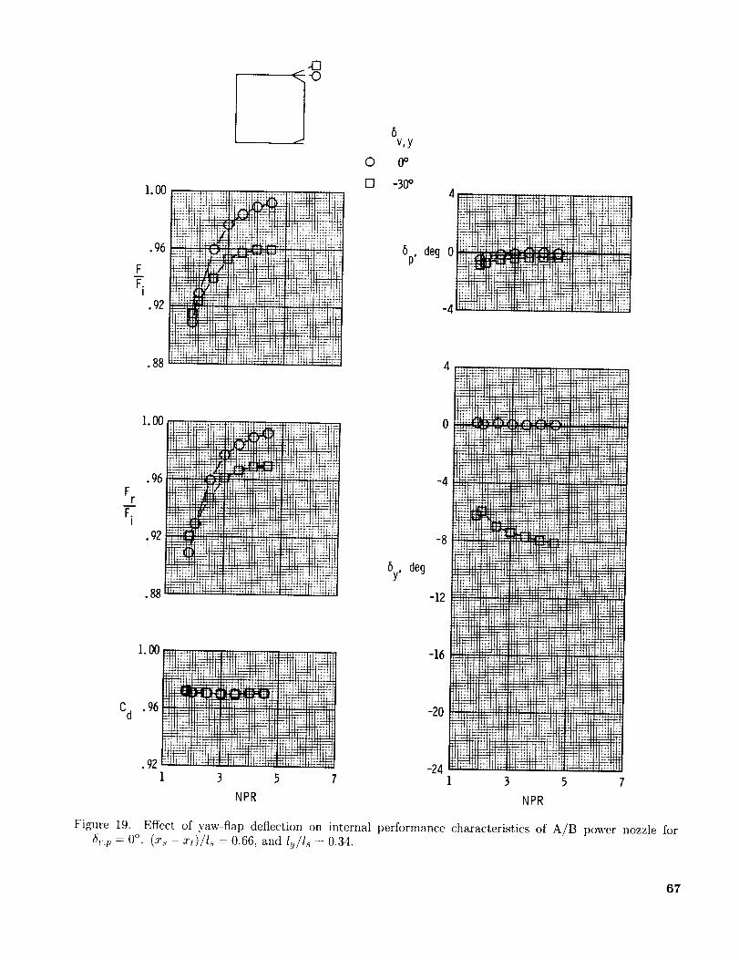
O
6v,y0o
,00 ............
Fr _ ,_.,.,._
• 92 i_
• 88 t
1.00
Cd . 96 +_
444 _44_-
3
ii++j r+ . _ _ , : ++++,._...... + ....
5 7
NPR
0 -30o4
6p, deg 0
-4
-4
-8
6y, deg
-12
-16
-20
-24
++++._+
_mmq
++_+.++,_+++
f fft-t-r_+
gg+g_
+e_rt_*q4-*+_44-
++_.+++
rt fr_l-rH_
;;;;;;J;Pl!ll
_TH_t_
fl_t44,4_4_
NI_II;[IIPIIil
writ'1ttlf_+f
3
NPR
"HlS*_+_yi_f|i I,iItI
, :!l+t!',+i
Figure 19. Effect of yaw-flap deflection on internal performance characteristics of A/B power nozzle for6v,p = 0°, (z.s - zt)/Is = 0.66, and ISI s = 0.34.
67

92
LOO ! 5_, _eg -z_
C_ 96 T12
.92 3 51
NPR
Figure 20. F_ffect o{ ),aw-flaP deflectiOn on
and (a:, - _t')/l' _ 0.31.
ta) 1,_/t.,= o.a4. o°
_uterual performance characteristics of R/B power no,zle for &_m_
6t_

IG
- _..]-0
I
Z
Fr
-KI
1.00
Cd .96
.92
•._ _ _t_
1
NPR
iHi[tt11- _ Trtt_lftl
5 7
o
6v,y
0o
-30°
8p,deg 0
-4
-4
-8
8y, deg
-12
-16
-2O
-24
(b) _/Z_ = 0.69.
' '_ ............ _::'A I" L _ "_
_+.
.++_ _
ti:*_tt:
_44444_
t11t_-
! ftff
7£;_J
tttffltt
NPR
'_+!IIii!S
**_£ :_;t H!J
1_tt _ t_t_r
ttl_
+*+*
+._+_
_÷
444_ 44_4 H4
t t_t -_bft _1_
Figure 20, Continued.
69

8v,y
1. O0 _i i_{mi_J_i_i__:_HIII _H_l',..............._{iiilHlllI_
F _i±_i!NiiiiiilNNim,!ii_
.92
.88
6p, deg
I.00
F
_L . 96F,
I
• 92
EHHIHIIHHIII_"_J
IHilII_.,_.I.'l _IH[:I[H-HHIIHI_,UIHII:
iiiiiiii_EilH!illIFHil_._._ii!!!Hilil
By, deg
-4
-8
-12
Cd
1.00 __ .................. ,1_4#,_ '...............'.,.:.;_fllH__.......... _,,,,,,,, ..... H_ ..... , H,, ii-rl"31 ili i i 71 I#llllb
.96 _
•92
1 3 5
NPR
-16
-20
-24
(c) l_/ls = 1.03.
Figure 20. Concluded.
1 3 5 7
NPR
70

1.00
.96
FF.
I.92
•88
"El
0
[]
0
6v,y
0o
-20o
-30°
°e0
1 3 5 7
NPR
1.00
Fr .96
Fi
•92
Cd .92
By, deg
-24i 3 5 7
NPR NPR
Figure 21. Effect. of yaw-flap deflection on internal performance characteristics of A/B power nozzle for
6,,p = 0°, (a:s - zt)/l.s = -0.03, and Iv/ls = 1.03.
71

F7-.
I
1.00
.96
.92
•88
.84
.80
iii
" _-t__.... 7_,
!;ii ....:' ?Ii!=i!!
++ +q_.:_.:i :Lg.kf+ ii;q+{i:
;t]:i :e_: .......
t+_ H'I: _: rt::t:'_:
+_ ........
....... ._ _ 'vk ......
;Tb:{; _::,,;i:
_!_Si[: ::m;;: mi ":
...... _:_:t: i:iI!iL
! _!b,;i"= _!;!,_ ' L.,i_ii:i;;i; _r.......
i+_ :m:." : !.:! ,:qTiil
8v,y
O 0o
O -20°
O -3°°
8p, deg
6y, deg
28
i
24
2O
16
+{:71:.1.'>': _) T{xl7
771 ii:-r' ,t{tli,!:
IZiH;:
iE!i2pli::l:_:k 7_,'_i f1!77:.7
!; i_H!! :'_"*'_I_!,:_ ililiL.it,,]ii!!_i+ii;!_;i!
12
-4
!_i:,tj_-.riifi[il11,_UH _4:lit_p! f i t [' 1_:iI
,_.,:.t_,'I:" !_;Li!!i.......
l_l_mrt_!i:::.:l!:!ii:l!:..:.,, .;.......
cd .96 i_L_- li{[ii!_i'i_+_177Ffi_f.'-i:i!:ikHi;t:::__
• 92 ..... -161 3 5 7 1
NPR
3 5
NPR
Figure 22. Effect of yaw-flap deflection on internal performance characteristics of A/B power nozzle for
6v,p = 20.26 °, (_s - .rt)/l_ = 1.00, and ISl.s = 1.03.
72

FT.
I
>
.00 .....................................
•96
•92
• 88
.84 ll-t_t+tt _tttt
tt_wTl ........ t;i*:;Ht
_'_*_ *_t N """_ .......
.......... 1_tttIH
........ N_Ef!
0
[]
<>
v,y
0o
-20_
-30°24-
20 ;_¢:H_t
_p, deg 16 fi!F
11111
81
NPR
Fr
F.I
Cd
1.00
•96
.92
•88
Ltd.
1.oo
•
1
l_rt_ trtt t
....... ++_.+÷.
......... ttt,*_ _!;;., ,
6y deg
.....
ttttt _
4 [i_:J
FLid_
r_t_ft
NP.I
112 :_'_E_1:
-15 .....
........ mttt:tf_
.... Y f _ : _lff_ _ ftt#f_, fj tf-_ft_!f
3 5 7
NPR NPR
Figure 23. Effect of yaw-flap deflection on internal performance characteristics of A/B power nozzle for
_,,;) = 20.26 °, (5% - :ct)/1.s = 0.66, and lt//I._ = 0.34.
73

5v,y
O 0_
-30o
Fr
F.I
I.O0
•96
FF.
I
• 92
6p, deg
24
2O
16
•88 12
i.O0 8
•9(5
•92
•88 0
6y, deg -4
-121 3 5 7
NPR NPR
(a) ISIs = 0.34.
Figure 24. Effect of yaw-flap deflection on internal performance characteristics of A/B power nozzle for_St,_ = 20.26 ° and (xs - xt)/ls -- 0.31.
74

_FF.
1.00
•96
•92I
• 88
.84
-'-'_:_- : ;.1,:_: .7 _; .:':l!
-
:iiX:!!ii_
:;i!ii!:ii_:.i: :lit
' ii_?!:!!fi.ii:
:::}tS,i_::.:!i!i;i;;i:#.!!i;
_l*,;:[t ":i: 'E
::i_i?iiiii:i, 1
0
rn
0
6v,y
0o
-20o
-30':'2O
16
6p, deg 12
!:! il;j!:!!!: %,.,ii2_':/_R!?:!i i1:;;::ii!it
!F:.2 -t:/-'2i;i:__i;?_!;iiF_]F: ?!.iii;: ;i:::1
_::.+4,14q_=:qli.,,.g-4:'-: $:;r,-::L::".:-:'_mt. *::1: I
_i;!ti-_:',+_; i :;,',!ili _r!;:,!tL% ..... ii T,•_i'::i_:-_4i':i':t,!!i !:!!!
....... -;aa&"E *{:.._.'._ .:a:. ....... _:
::>'i t:,_:,it?::,i::_i:{5!;,_i5i;i:f_jgq.i"i_
Fr
F.I
Cd
1. O0
•96
•92
i:::7 i:!:: ::!! 5:!i.ti!! :i!.!!:+__i;;i!ii::i__:: • :i,_:_il<: < i!:i,i-
.88 6y, deg
1,00__ , • *, _':;', _ ;1_ ; i_
• 1 3 5 7
NPR
(b) l_,/l, -- 0.69.
NPR
Figure 24. Continued.
"/5

0
[]
8v,y
0o
-30 °
/El
-O
Fr
F.I
Cd
I.O0
....
j_ H'!t_
F_..02F.I
1.00
•96
•92
•88
1.00
• 96
•92
• 88
_£: H; q: i: :H:: t -_::_ I:' ]XPfV:
itiiXt_Fq!i
ih H F
3
!!;Um::m!:i ;i;:t_it!@
E_£7i!:ji !ihfti
......
.....II ii!]$
NPR
24
2O
16
%, deg
12
i_:!ii!i!iiliN
tqi xl
::tli!i;
-4
By, deg -8
-12
-16
-207
(c) lSls = 1.03•
..... HI¢, :m_.... it
!i!!il! i_!:iJ4i'xll "_til[:::::_;atX:S/7:"41m]} "';'"!U!! t d.],
H'iif15ii; [I .,._*..._
!ifitl ! _;!1i:!Ilk l!it!t_
;[_:;]! 'ii!il}:'i ;! tl_
,u_ :'j{it_]!it!'h::T
_t4_ ;_4;N41|
;:: :HUH
"t_'t ttttrtl",t
Rft Iif@HI
:1 _N!IHIt
<:: .......
>ti:tl
T!! H ;Ikff
!HdN_tl4
Ht+++.+Nt_'Lt _t:lt
5
NPR
! i!N i .**H,,_
;ill i..... +.l_,i
NN_
@i!t ,: ii*
u'.!, NiN_,ft
,,,- .... £I; 11t
h+_H_4f:idtH,_4 F+afl:_#i@
:_!t_iU H: ,11;Ht-+H_
i:.'t,::m: Ii!!_-'_
Figure 24. Concluded.
76

/O
1.00
.96
F
F.I
.92
•88
I.O0
F
.96F.I
Cd
•92
.96
1.00
.92
•881 3 5 7
NPR
tip,deg
5y, 6eg
6v,y
0 0o
[] -30 °
--0
4
0
1 3 5
NPR
(a) ly/l_ = 0.34.
Figure 25. Effect of yaw-flap deflection on internal performance characteristics of A/B power nozzle for
6,,p = 20.26 ° and (x,_ - ,rt)/Is = -0.03.
77

1.00
•96
FFi
•92
•88
1. O0
F__it .96F.
I
•92
6p, deg
8v,y
0 0o
F'I -30°
Cd
i. O0
•96
• 92
•88
.84I
iii!i
_H4_ :tt!:; J
[:211 H: tL
3 5 7
NPR
By, deg
-4
-8
-12
-16
-2O
(b) Iv/Is = 0.69.
Figure 25. Continued.
3
NPR
78

i.oo ......... i i ............ii:i_:LLili:: i :iLii_!_iilL!.:i_i!_!!:iii_:;!iiiiL
.96_: !::: :' ii:i:i_
• 88 .... : ::,:i--i, -;--.,I : . :, :%i" :
Lode_+: t:::i:
Fr
F.I
1,00
,96
,92
•88
i:i iiiii[;i_::,!_!:ii:::i:i_i!!_i_!_:il;iil;!!/!l
_t_i_ifiii_l_ii_!l_:_:':_:_ii!i!i_il
.q6 iii_:_t:_;:lJ!':':i;_
Cd .92 _ : ;_::ii_;ii_!i'_m":':iii!ii!i!il]ii:ii![
II7!'!EI ........
_i:]:!;11!Li?}?15
i_i:]i! ..... !i!_117i i!i!
I
0
[]
0
!i!_!i!ili_:i;ii:: P,:] v/i
i_!_!ili::ti;il;i!)!
5 7
NPR
8v,y
0o
-20°
-30°
20 i; _ i:!ii:i L ::i:: ::!.!_ : :t
16 i_i;i!i!!_!):]: :!!!i,;ili;:i_!_
7__. _
:_ 1; : L : i/ i
1 3 5 7
NPR
-4
-8
By, decj
-12
-16
-20
-24
(c) lu/ls = 1.03.
-'TT-":""--'-_'_ _T : .... .
!::i i_;:ii_i:, :!:!!iFii: l.i:_i_i!: !I
_7!:_::[ _22:-' r:_ i-:-_
1: :I?':i'I
: , _ , i ,i , ;i' ,i ;_;", l
3 5 7
NPR
Figure 25. Concluded.
79

© Q
_ _ iiiiiii_iii!!!iiiiiil)iiiiii_
_!!!!_!i_i_i_iii[i]iiil]]!!i_!!![!!!iiiiiiiiiii]i_-
x
I
x
©
©
©
% o
80
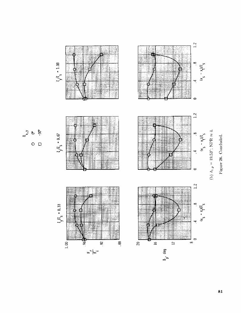
o
r.,j _
;liiiiilii;!i!_
li!i_.:t?
P:t_!p
:_:
It;;:; I
_N_58
iit;...:it_
!;i@
iiii!iii_
u}_!i!ii
oO
x
I
X_/")
O
>- IB ,,-,t
0 []
oO
It
0
,--i
iZirilY"
_1 uu
.....li!_:{X:
_4
h_
!_ii
::8 kt:i
IHI
lliiii!t
H_
!,[h;Ht:
.... E
_il!!iIoOoO
i_.:iHhi .- ,
g_
z:f ::;ii 4iXX;:
; _:; _:1_;:_;::
u _.=_, bZ)
81

1.00
FF-- .96
I
•92
LylIs
O 0
[] .33
0 .67
1.00
!:_!_!_:: i.iLi_ _ti_i_
;4ffftw+
_Ii Y!/fi:_q.i:
:-i::7_[<ii:i<
o [] <> A
r,
NPR
Cd
3 5
Nl ,i+_]=J1:i7: n 1t_::
!:i'i{'_ !:d 3;? _ "
3 5 7 9
NPR NPR
(a) Dry power; 6v,p = 0°.
Figure 27. Effect of undeflected yaw-flap length on nozzle internal performance characteristics for 5v,vand (as -xt)/Is = 1.00.
_- 0°
82

FF.
I
Fr
F.I
1.00
.96
.92
•88
.84
I.O0
.96
.92
•88
0
[]
<>
&
ly/Zs
0
.33
.67
1.00
O
Ca:: c .__T_ :. iLL:}2::_
1:iFi:t - x t! !_;i_:?i{!1:t
]
• ' : '4' " .': I: -I;1! _ !, k- ,:I • : : _:;t
I
6p,
[]
L28
24
2O
deg
16
12
NPR
Cd
1.00_,-=-._
i i!!! ilFiiii;1 ,_, HI :t:,J;.:
iii_#di,'dil_!.96 i! L.ii_;:L_,
_!ii;_;!i'!:i]
_'! i!_i_:; ' ,i!12
.92/'!ii:!! iF!!l3
_/1_ _: ,#1::! i :;ti::ii'2..]
:: .J!-_.L!_ itr: _-:,r.: _-]l.t _:::1
: i:!!i: ii i_!: _:;;i:iii; ; :Y!;ii;v:::t5 7 9
NPR
6y, deg
i.iF.i: t::;:i?::
¢ ;Y,;t_:;!!;:t!i;=_;;,_ ;;_!:ii!'i, :_;!_;;_;_Y.;!+!il!i,_ili;I`
_4i: :: ! UI!!Y 5
NPR
(b) Dry power; ?_,p = 19.53%
Figure 27. Continued.
83

Fr
F.I
1.00
•95
•92
•88
1.00
•95
•92
•88
IIHT]IIII|III]IIIIIIIIIIIH-H ........._.......
ii!iiiii_iiEiilfii_,,m,_-j!.-.._,.iijji_i_
............... ,........ i4iiiii!!!iiiii[iiiiiiiiig
!!!iii_iiiiiiiiiiiiiill}i_i!!!iiiiiiiiiiiii+II]_IM'",._,=IIIHMH|IIIIIHIIIIIIINHI_H_IIHHII_II.,,H,,,,,,,,,H,, .......,,,,,,,,,,,,,,,,,,,,,HH,,,,,
_iiiiii!!!!!!!iii_
iii Jii',iiiIH Ii',I[I',-'I_I',',I[II
"!t!!!!iiillii!!}!!i_}iim_q._,-_.i,,-_,,
I+t+I+l-t-_ I I I H
_iiiiii N iiiiirii-H41__._-_.',IIIIIIIIH"IIIIIIIF
-'H ',IH IIH JII_'?-II_;M _I',IH If',IIIf',I[I',IIIIIMIII_II;',I",I:'._',I',IIIII;II11"II',I',IIIIII_V._III'I',IM',ITIIHIIIIII,"IiIIIIIH II."IIIIIIIll II[IIIHHI IIfill
•............. _'d I+H_II H Ill M Ii_ ....... llilIlllllll',llll;I ',',Ill l[-_i'- l',;l; ll:: l l; ;i ',', ill i: l l l l _I
_!!!!!_!iiiiiii!!!!!!iii!!iii!!!!!!!,,_,,!!;J_'%ii ii }iiiii!!!!!!iil} iiiiiii'........................ H, ..........IllIIII-".'.'-'IIIIIIIIIIIIIIII-H+IIIII IIIIIII H I III IIllll II II Ill ',I ', I ', I III U, ',I ',I ',I i
i0
0
[]
[yl[s
0
1.03
[]
5p, deg 0_,,_ _'+'+_'-_'-'
....llI[_Itll{li
1. O0
Cd .96
.92
IIIIIII[IIIIIIIIMIIIIIIIMIII,,_,H_-_IIIIIIIIIIIIIIIfl
!iiiiiiiiiiiiiiiiiiiiii_m_iiiiiilh_iiiiiii____
1 3 5 7
NPR
5y, deg 0
-41 3 5 7
NPR
(c) A/B power; 6v, p = 0 °.
Figure 27. Continued.
84

_y/[s
0 0
[] 1.03
1.00
.%
FFi"
°._
1.00
Fr .96Fi
.92
0
28
24
20
16
G (legp'
12
I-1
_ri_
I. O0
Cd . 96
.921 3 5
NPR
I7
4
Gy, deg 0
-4
(d) A/B power; 6v.p --- 20 .26°-
Figure 27. Concluded.
3 5
NPR
85

I.O0
•96
F__.92F.I
•88
-F_; ! i_::i*l_ :'. ii
8p, deg 0
:_!i-T_I,_ _:I-'-_
r':_ t_:!_:H,;:
-41 3
* + "" I _ 'iI r I H
";iu-itl!<, EIi_: :iJ;l:_::_-:+_
5 7 9
NPR
.84
1.00
FrF__.96
I
•92
ii!_fi;ii!'_d_/ ,:w ,' i1:Y
T;:iF_
!11!:' ti+;::!_:-l_,:, li:::_','_
2;i !1i:;'
i!;iiii
iU_;_i:l!ily ii
0
---%I
I
__J
[]
[y/Is
O 0.33
[] .67
Cd
1. O0
•96
.92
•88
iiiii!:;ti: /i -8
!Li]Lii];;! T+=_:ii ::_;,,L; -12i_4m-'_]!!--.!i_
_+: t t;_:: 5y, deg -16
£2riis
-241 3 5 7 9
NPR
........ F++++W+_p}H!_F:_F+S +++IL,+ilT+_++u,++-!
+++"++"+ "+-++++"+_+++_+_++@i_++++_;_+::j t[ i!q_+++,
__ ...... i_
.,_+.+.++,___ _+_++.+. ,, •
.............. , ....................... -- ...... F;;; 1++_1
3 5 7 9
NPR
(a) Dry power; 6v,p = 0°; (x+ - xt)/ls = 0.33•
Figure 28. Effect of deflected yaw-flap length on nozzle internal performance characteristics for 6v,y = -30 °.
86

0
[]
0
[yRs
0.33
.67
1._
0
1.00
.96
F__.92F.I
.88
.84
Lq:!ii!El::jl.m_vx:lF:(tt-:_;
ii..=,.::q:tiF!:::i,
_:;"t$L:; 1:::, !
p hh,TMi:n ;t::
Film!:;:ii!
i_.:iii!!!ii!:::i_:L'iii!:: ft!qi_:
!!!i¢ii ii!ii:!i!:
Ut_T4_t:i]V:i;1; _
ii:iKiii !::::i;.';:: .:;:t;:-:
,!ii t_:i:iiiii:: :-i:;!_!il_i: :_:_iiii:_::i]...... :: :i::.!i!!L:i :i:
'.!::i_!5.... 'd.::,i:
I:!;" _ :iF !i!'m:::_:_;::CI.q.*:.........
_m:ii x: :_::::h:
24
2O
12
!*i_::ii_Is:S'i;ii:['¢:i i::!i'.:i!!, :ubu L_:
:,_ _!.............: _::::, :i: :::i;il}!:_,.!i!;i!/:ii
_iiii!¢i'_iT?i:i
?iU. i U:iii':: !!_iF! " :7. !:!: !:i!!'.xt :ii:t!ii_
3 5 7 9
NPR
I. O0 ............. :
Fr .%_gi x_ ....
92 ........
Cd
,00 ......................
i:_-__£_ _ .....
5 7 9
NPR
....... - • L; ,+;iiF_
.:_H..L .. n_., ,
" L::_ . =.i ,-.._ t_-.£4
T:_ :-::m::2:i _.t-;T_::i:
3 5
NPR
:qt -'; .....:;:i:h_l_!::ii::i:
:i¢ii:!
!!_i!;il:i"ii;_}i
7
!d::_Tq:::t+it' qr'
_Hi!F:i
ifi_.-b:[_:_:i;fl,i:
(b) Dr}' power; _,,p = 19.53°; (x.s - xt)/1,s = 0.33.
Figure 28. Continued.
87

1.00
.96
FFi
•92
•88
1.00
F.._[.r.96F.I
•92
Cd
.......
V , iE
M_tl
;SI
i:_i;"':_¸¸....
i°_ _i ._
_ _.
1.00
•96 _,_-_-,_*_._.+._+_.................... Itll
.................... _||liI'IIiiii_ .........
•92 ' ' i_'1 3 5 7
NPR
0
[]
<>
ly/l s
0._
.69
1.03
6p,
Oj _j
4
deg 0 __
I__t___
-8
6y, deg -12
-16
-20
-241
1t:
3
NPR
(c) A/B power 6¢,,p= 0°; (xs - xt)/Is = 0.31.
Figure 28. Continued.
lJ_]g_
a4_
if!
g
N
5
ms_m
T,.'T_,_'? *?..'_T_:
44t-I .M4444_; I
NN
i;i;[_4}i
44444 **44441
7
88
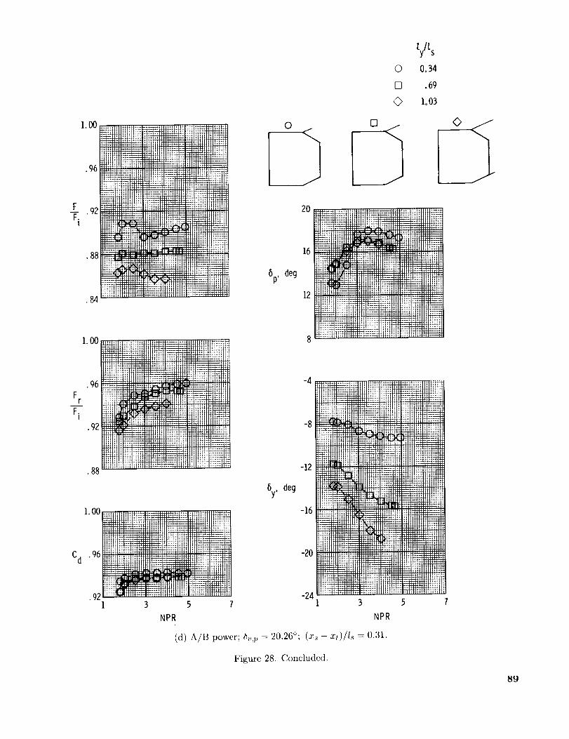
[] .69
© ioO3
__F .92Fi
•88__,
_o0___
ffl_NNIRN_
Cd
i. O0 " " _ ' _L
•96
•___iI 3 5 7
NPR
5p,
5y,
0
deg
deg
12
I" t_ ¸
-4
-8
-12
-16
-20
-241 3 5 7
NPR
(d) A/B power; _v,l, = 20.26°; (Zs - zt)/ls = 0.31.
Figure 28. Concluded.
<>
89
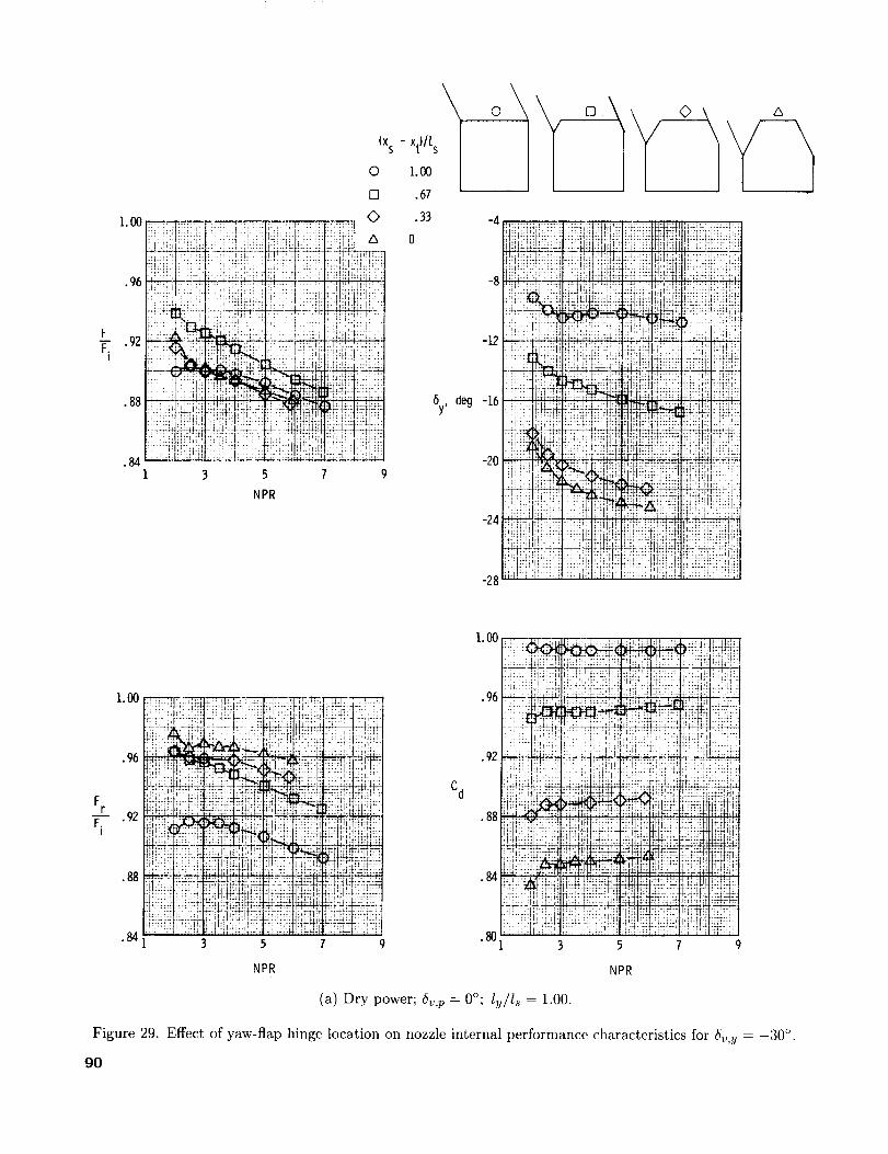
1.00
.96
FF_ .92I
•88
'il]!li_ii_!il.84
3
NPR
(XS
0
0
7 9
- xt)llsI1.00
•67
.33
0
By, deg -16
A
1.00
.96
Fr
F-'_'-"92I
•88
.84,
_ t,+i" i':'L.:di .'d!:brLl;h; i!t_l.qlh{i
:,_T¢ ':; . : _;;.i i ;_i1_ A ',J +,T!];1 7]
:i{'Tq_i
•%i_; _ _, _: _t_ _.. ,=. . .... .+. ].++f -
:!fi i:A'_:;!:{ !itr.Tii,:_ iLi:: :,::;E i]i,i7i77
;!:;,:, ri+]:,: tLIL:I_I;£ELIhL_u_: ;_!!!;:i_II'._i_t+.,,<_I!11!! I,:.: .,J; _tt:iim
.88 ;:i[??::'mr.<:-m+/,[::i Hi-:l!fit _ i:t4 ] r ;:T]:_ +I4;H'IIi{_]]r{. +.,: t:I ;;i:+:_ _)_,] ;:TjCr;:]
._F_74JI <7
84 .+-, '17 (+ii/_ v:wr. .mi:_ _
• !:lJ-i t(Fr;; :dx ::.ti_iii_l_:!::!_:_¢:4",.... '_, ' '"801 3 5 7 9
• 92
Cd
NPR NPR
(a) Dry power; 6,,,,p = 0°; ly/ls = 1.00.
Figure 29. Effect of yaw-flap hinge location on nozzle internal performance characteristics for 6,, v = -30 °.
go

1.O0
•96
.92
•88
FF.
I
(xs - xt)/[ s
0 l.O0
[] .O?
0 .33
L_ 024
20
16
6p, deg
12
4I 3 5
NPR
1.00 ii_iiii i::lli!iI _ii_%ii::i::!i
.96 i:_lii:_! !_I.... _i::,
........iilL•92!i!!il':_':!!!_'_
c_ i!!!_i:_:"._ _'_[_h;!lll_.
•84!ii!!! !ii!!i I_!_::!!:=,::i_'.-¢_!l!ii
"801 3
H+,-_t,
....... _H
_4+i.... . _iitE
:: _i :_:_ H;:!:--+!!!
, _i _ T:!l:i_i!!li.:]i'_ ,iii!!!_!
fi i!_idi'-::
i!_lii!_;Nt
ti::t *:: ::P :! , :!i _'ti ili_::!ii_!
5 Z
6y, deg
NPR
(b) Dry power; G,,p = 19.53°; luffs = 1.00.
5
NPR
Figure 29. Continued.
®
.-4++:
1
;;,.:
:/iiiH
::v:
H_H_
i!Ci
9
91
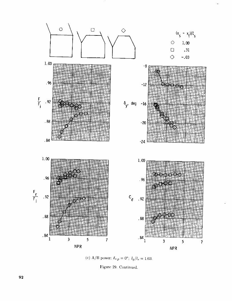
lI. O0
•96
F_ .92
I
•88
.84
0 \ []
..... i'" I!"I .......
]_Itltllllll_l_l_ .... . t. ' Iil ' ] [ ' I' _q ,
By, deg
-8
-12
-16
--20
-24
(xs - xt)It s
0 1.00
[] .31
0 -.o3
!12,, "
................... :::_i ' j
.96
F iiiiiiiii!!!iiliH41_iiiiiiiiiiiiiiiiiiiiiliii_
.92I
•88
.84
l::r_ :":_L_,':;:::::::_ ..... : !!_,"';i];;_.............. llJ •::: .............. iiiiiiiiiiiiiiiiiiii:-_iiiii::::_::::!!!!!!!!i!!!!!iiii,,[lll
iiiiii_=!:i::/!!!'"'_
3 5 7
NPR
1.00
•96
Cd .92
•88
.841 3 5
NPR
(c) A/B power _Sv,p = 0°; ly/l_ = 1.03.
Figure 29. Continued.
92

.92
•88
FF.
I
.84
.80
i.O0
•96
Fr
-- .92F.I
•88
•84
I. O0
.96
Cd .92
•88
.84
H:_::I;! 'ili:!i i!iih!q
i!il)i!i!;!_jili;i:_
i!_ml;iil}!iii!ill;!_!'_l:
!iq?iig
i!i!ii_L::,,:! ........i_i_!_i:i!i!iii!i;iii
;!ii.i_il -:'v'i_!;:iihq i;_;_!].,i!;h:u _
L" :_hili!;!_
r:r:_i:l: , ....._!b!!i_. :_: i!i:
iii_ %"
ilii_: :}2 :I::t d: :H
_i,)!i!!il
)li!t:i:i
_ii!:!:!
i!iiii4_
tHiEE:
i 4b:!
!i:ti!_i!ii!i_iill
!iLiilh_
dili!!i!
H:i_;I!i:
iii!_$111_i!ilii!i
i,i!i)i_i
qI:b:_:
ily_"•j!!i_
_i!iUiil
i!); k
r!H,,i_
ii.iii I
!_PiL:i
i1!:th;_
!'_ !ib::L];:i!i i i_i
!Ei!ih:
!li!d :i
i'J::!;
11!11!1
_:hi:i:
.........ii!}!ilil)!i!i!ii!lil;!_i!!iH<i_:......iIi!_i;_
....*..... lil !i .....
::I_M!?tih!i_!ii_i_{ {ilili
:*::Fq_
_!_}i!I,!!;i!i!i
:i !itS:: i[fi!i!!ii ;;:i!ii_i,:Gq.:; :_:T:,lqii!i:!iili;_iiih:i:!i!:!i!i<;iiii ii:iii:i__;;>,_:
\
i0
_p, deg
(xs - xt)//,s
0 1 O0
[] 31
-.o_
\
28
!r:,_:/i.U
_i)ii!i;i_17"'_,
i_!))i)Uj_l(ii!F,
_):i:;:ki:
)))jL.'-))#__)),_)
)i)iU!))l:"'i _: ::='_
-4
_iili i_ii ii_i!ih !{_!::::: '::_":'_:!) iii:!iii:iji':!ii!J}_
;H:;;:d i_!_Eiiii
::::,a:,::h_!}_E[ii_!E!)!Em:t::t__,;:,;;_,,,._:iiiii,ii!iii{$i_ii
_ili!i!L!i!!fiiiiiii_ii!?}}iiiiiiii!tili)!)iii.......::!,t.i,,.1!_!! ...... :]: -,! _-i F I:t[:!_ t?t!i[Lt!
-12
6y, deg
-16
1:$ $_:,::
);i_);;E!-8
-2O
-243 5 7 I
NPR
i: ) it'_:t :I:!f_:{!,
(d) A/B power; 6,,z, = 20.26 ° l u/Is = 1.03.
NPR
Figure 29. Concluded.
93

I
_ r _t
_111
" _...... !!!:rill , r ,, ,_
_. __:F_ _
/ I [_ J I I ] ] I"' , ......... H-H_tbU-[_H
ell elll
i I I
oo©
II]lrl •,_ J_-H-H_-I:LIIt[/!
:il;_;iiA i_H!!!!!tJ!!i!!!J[ii!iiii iiiiii:,i_
[ l] ] [ii [ [Ill} ill 13 II
_IH .................. lllll
-I" "P-_t_ irriirrlill:
........ f PNt_........... I[III I I11 I_l I1 }l / I i
I! IJ I I [! I Ilrirrl ] ']IFII _ t lilt I I_11_]l!l : _lli i r l_[llilll
IIIII
Fr
F i
1.00
.96
.92 _
• 88
N-4
-8
0 O. 33
[] .67
© ioOO
20
16
6p, deg 12
8
0 .4 .8 t.2
(xs - xtJ/t s
-12
-IO
-20
-240
(b) Dry power; _,,p = 19.53°; NPR _ 4.0.
Figure 30. Continued.
.4 .8
(x s - xt)/t s
1.2
95
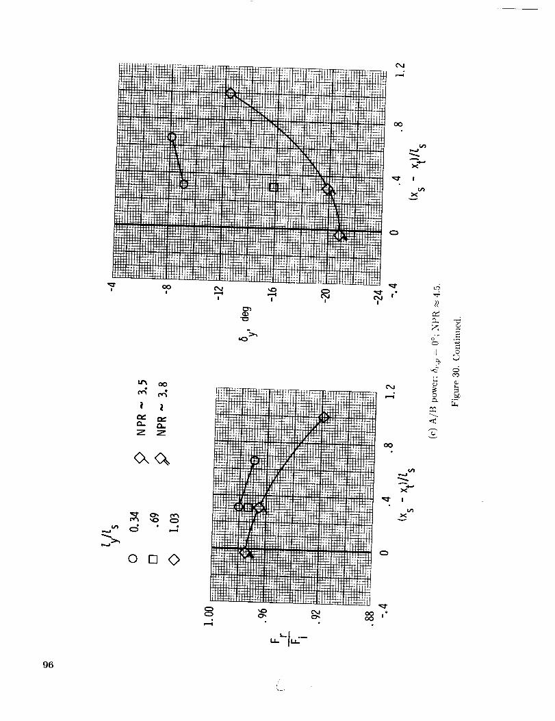
oo
x
96
!!
0- 0.
Z Z
_ °
I I
/
I
IJ c
c_

o
Z
0,,
i •
o©
ili,!iiitili!
oOoO
i
oO
I!iii ii!_'i!ii'_ii!!_1_ ff'M i °
;2,
©
97

1.O0
.%F
r
F.I
•92
i_! _ :_:_tiL_
/Is " 0.33
it:; '"_
V,I:}
0 0_
n 19.5_o
Jls " 0.67
i_I)i{
._ _._
!!:!ii?iiiiitli)!ii?_
.......................
(NPR ~ 3.0)
(NPR-
:/:!i)!_iii::!ii.....
:': _i U)ii
!= _ii!_'"'=
y
..... :_:'.I__iti!!ii
_y, deg
::rTrm:
_r_
'2I_r_
_++ +)
1.2
LTT:_.
))!i
)!))iliiii_ii::]!)_Hii_i.!)_iii
.....!_i!_i!iii!}_!ii_iii_ i£iiIiii!...... _"-:11._[:::,_!ii!i .. ;:;__i_t,:_!!
_'-+" ........ ' [!!2
r ?T!?)_TT
.4 .8 1.2
(xs -xt)/ls
i_::)i::::!::11)i)?i':i))!):£)i))))))))})E ""
_Fki_ r_
0 .4
;:_i;)i:.))ii)i:::.ii))':_))i:))i)))1))::)))))Ji!)i,_T_!_T_))))
_Z2_22 :!2.
.8 1.2
(xs - xt)/(s
(a) Dry power.
Figure 31. Effect of pitch thrust vectoring on nozzle internal performance characteristics for 6v,g = -30 ° andNPR _ 4.5 unless otherwise indicated.
g8

? i!ii!iii,i_i_!i_ii!ii:iiili_iiiii__!ii_!i!
f
i•
O- Q. rEZ" Z Z
o, o_n,
© []
i
i•
-4
©
,<
©
i
Z":>,
99

Symbol
O
[]
<>z_
E,
[3
8y effector
Round port
1 powered rudder
2 post-exit flaps
2 downstream flaps
2 downstream flaps
Div. flaps (of cantednozzles)
Previous concepts; NPR near design
5v,y, Powerdeg setting
+_5.9 Dry
_+20
A/B
Dry
Approx.AR
3.7
3.7
4.6
3.7
2.8
3.5
Reference
13
13
17
13
14
15
Comments
Conf. P1
Conf. R4
Vane Vl
Conf. F6
Conf. 3 (Dihedralangle = 45 °)
1.0 m
%
.8
.6
_y •
5v,y Ix.4
.2
00
Current test; 5v,y = -30°; dry power; AR = 3.9
Symbol _y effector (x s - xt)/[ s
2 post-exit flaps
2 post-exit flaps
2 post-exit flaps
2 sidewall flaps
2 sidewall flaps
2 sidewall flaps
1.00
1.00
1.00
.67
.33
0
[y/Is
0.33
.67
1.00
.33
.67
1.00
[]
• O
I I I I I I I.002 .004 .006 .008 .010 .012 .014
qr_y, perdegree
O
tIncreasing
performance
I I.016 .018
Figure 32. Comparison of yaw thrust-vectoring concepts of 2-D C-D nozzle at an NPR near design. Yaw-vectoring efficiency is given as function of vectoring performance-effectiveness parameter.
100

Symbol 5p effector
O
[]
O
A
r,.
r-x
(_ v,p '
deg
Div. flaps +_20.3
Div. flaps _+20.3
Conv./div. flaps +_11.7
Div. flaps ± 20.3
Conv./div. flaps +_15
Div. flaps (of canted +_14.1nozzles)
aConf. 3 (Dihedral angle = 45°; twin
Previous concepts; NPR near design
5v,y, Power5y eflector deg setting
Round port -+5.3 A/B 2.0
1 powered rudder _+20 AJB 2.0
2 post-exit flaps Dry 4.0
1 downstream flap : AJt3 2.0
2 downstream flaps 1 A/B 2.3
Div. flaps (of canted _+14.1 Dry 3.5nozzles)
engine; single nozzle deflection of 20°).
Approx. Reference CommentsAR
Current test; dry power; AR = 3.9
Symbol _p effector
• Div. flaps
5v,p, ,_ effector 5v'Y'deg vy deg
+_19.5 2 yaw flaps +_30I
IiI
(Xs-xt)/Zs
1.00
1.00
1.00
.67
.33
0
13
13
17
13
14
15
Conf. P16
Conf. R16
Vane V1
Conf. t=23
(a)
[y//s
0.33
.67
1.00
.33
.67
1.00
1.2 -- 1.2 --
5p
5v,p
1.0
.8
.6
.4
.2
0 (3
-- &
_F-- Increasingperformance
1.0
.8--
6y
-- .6 _--L5v,y
E,.4 --
.2-- /x• Increasing
_ performance
o I I I o I I I0 .002 .004 .006 0 .002 .004 .006
qrsr, per degree qr_r , per degree
Figure 33. Comparison of multiaxis thrust-vectoring concepts of 2-D C-D nozzle at an NPR near design. Pitch
and yaw thrust-vectoring efficiency is given as fimction of vectoring performance-effectiveness parameter.
101

Report Documentation Page_a0c,_a_ Ae_Jna _llc_ anaS_ace Ad-n,n,Mn]tJ_,r!
1. ReportNAsANO.wP_2973 12. Government Accession No. 3.
4. Title and Subtitle 5.
Static Investigation of a Two-Dimensional Convergent-Divergent
Exhaust Nozzle With Multiaxis Thrust-Vectoring Capability 6.
Recipient's Catalog No.
Report Date
April 1990
Performing Organization Code
8. Performing Organization Report No.
L-16632
10. Work Unit No.
505-62-71-01
11. Contract or Grant No.
13. Type of Report and Period Covered
Technical Paper
14. Sponsoring Agency Code
7. Author(s)John G. Taylor
9. Performing Organization Name and Address
NASA Langley Research CenterHampton, VA 23665-5225
12. Sponsoring Agency Name and Address
National Aeronautics and Space AdministrationWashington, DC 20546-0001
15, Supplementary Notes
16. Abstract
An investigation has been conducted in the static test facility of the Langley 16-Foot TransonicTunnel to determine the internal performance of two-dimensional convergent-divergent nozzlesdesigned to have simultaneous pitch and yaw thrust-vectoring capability. This concept utilizeddivergent flap rotation of thrust vectoring in the pitch plane and deflection of flat yaw flapshinged at the end of the sidewalls for yaw thrust vectoring. The hinge location of the yaw flapswas varied at four positions from the nozzle exit plane to the throat plane. The yaw flaps weredesigned to contain the flow laterally independent of power setting. In order to eliminate anyphysical interference between the yaw flap deflected into the exhaust stream and the divergentflaps, the downstream corners of both upper and lower divergent flaps were cut off to allow forup to 30° of yaw-flap deflection. This investigation studied the impact of varying the nozzle pitchvector angle, throat area, yaw-flap hinge location, yaw-flap length, and yaw-flap deflection angleon nozzle internal performance characteristics. High-pressure air was used to simulate the jetexhaust at nozzle pressure ratios up to 7.0.
17. Key Words (Suggested by Authors(s))
Nonaxisymmetric nozzlesMultiaxis thrust vectoringStatic internal performanceTwo-dimensional convergent-divergent nozzles
18. Distribution Statement
Unclassified--Unlimited
Subject Category 0219. Security Classif. (of this report)
Unclassified ]20. SecurityClassif. (of this page)Unclassified 121' N°' °f Pages]22' Price102 A06
NASA FORM 162{} OCT s6
For sale by the National Technical Information Service, Springfield, Virginia 22161-2171
NASA-Langley, 1990