Embed Size (px)
Citation preview
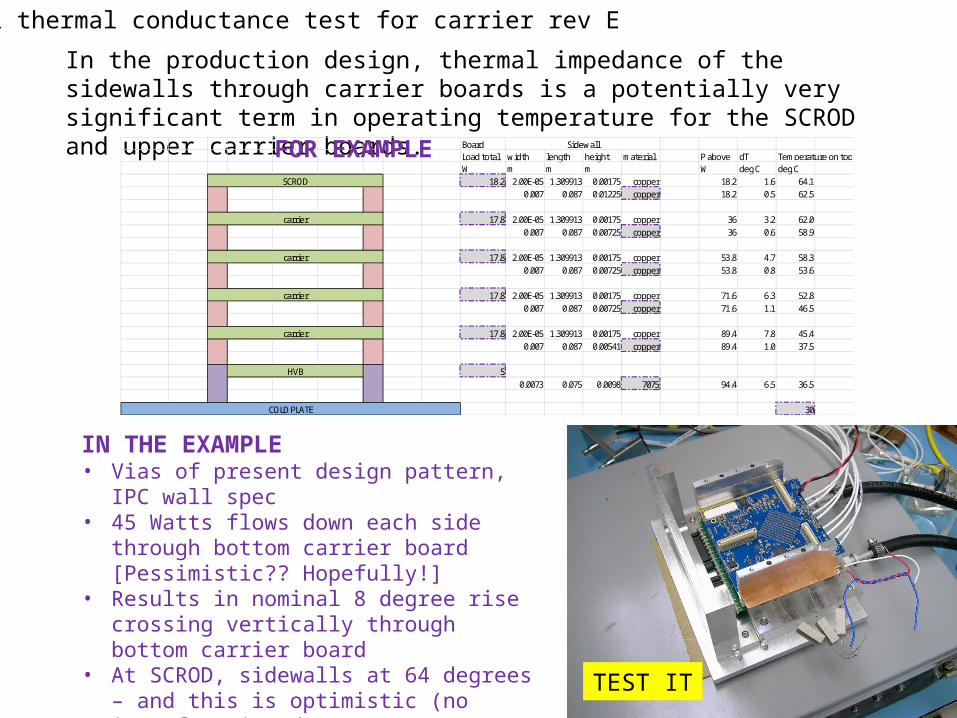
Vertical thermal conductance test for carrier rev E
In the production design, thermal impedance of the sidewalls through carrier boards is a potentially very significant term in operating temperature for the SCROD and upper carrier boards.
BoardLoad total width length height material P above dT Temperature on topW m m m W deg C deg C
18.2 2.00E-05 1.309913 0.00175 copper 18.2 1.6 64.10.007 0.087 0.01225 copper 18.2 0.5 62.5
17.8 2.00E-05 1.309913 0.00175 copper 36 3.2 62.00.007 0.087 0.00725 copper 36 0.6 58.9
17.8 2.00E-05 1.309913 0.00175 copper 53.8 4.7 58.30.007 0.087 0.00725 copper 53.8 0.8 53.6
17.8 2.00E-05 1.309913 0.00175 copper 71.6 6.3 52.80.007 0.087 0.00725 copper 71.6 1.1 46.5
17.8 2.00E-05 1.309913 0.00175 copper 89.4 7.8 45.40.007 0.087 0.00541 copper 89.4 1.0 37.5
50.0073 0.075 0.0098 7075 94.4 6.5 36.5
30
Sidewall
COLD PLATE
SCROD
carrier
carrier
carrier
carrier
HVB
FOR EXAMPLE
IN THE EXAMPLE• Vias of present design pattern, IPC wall spec• 45 Watts flows down each side through bottom
carrier board [Pessimistic?? Hopefully!]• Results in nominal 8 degree rise crossing
vertically through bottom carrier board• At SCROD, sidewalls at 64 degrees – and this is
optimistic (no interface impedance!)• At the SCROD, 22 degree rise relative to infinitely
thermally conducting carrier boards TEST IT
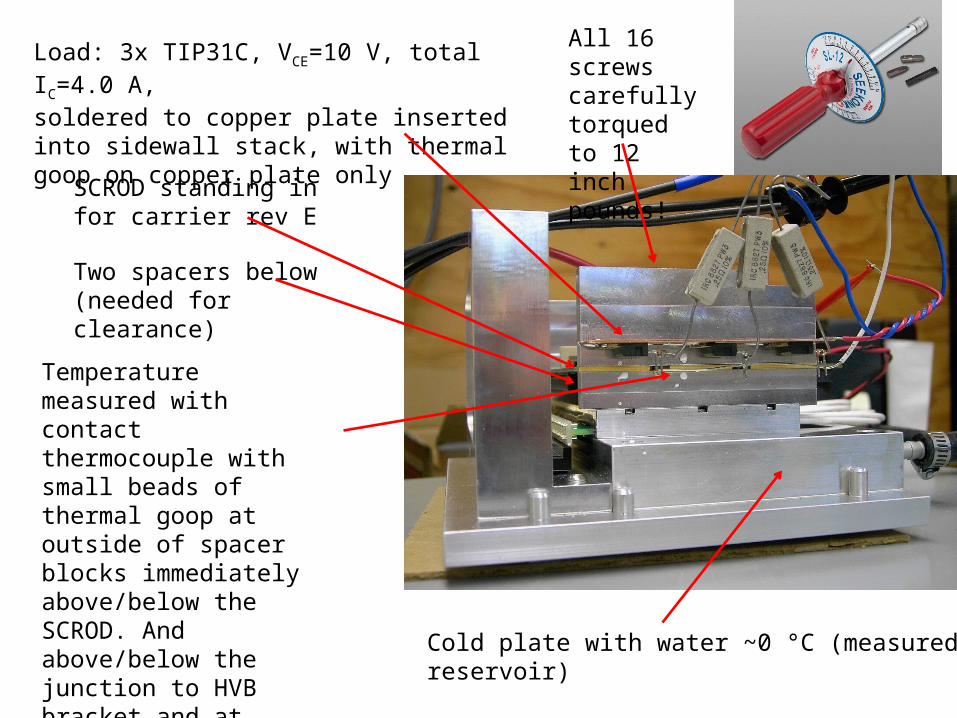
Load: 3x TIP31C, VCE=10 V, total IC=4.0 A,soldered to copper plate inserted into sidewall stack, with thermal goop on copper plate only
Cold plate with water ~0 °C (measured inreservoir)
Temperature measured with contact thermocouple with small beads of thermal goop at outside of spacer blocks immediately above/below the SCROD. And above/below the junction to HVB bracket and at bottom of HVB bracket, and top of cold plate nearby.
SCROD standing in for carrier rev E
All 16 screws carefully torqued to 12 inch pounds!
Two spacers below (needed for clearance)
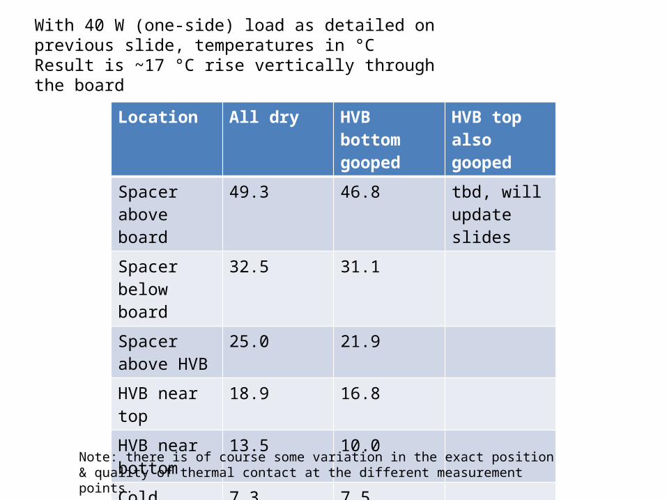
Location All dry HVB bottom gooped
HVB top also gooped
Spacer above board
49.3 46.8 tbd, will update slides
Spacer below board
32.5 31.1
Spacer above HVB
25.0 21.9
HVB near top 18.9 16.8
HVB near bottom
13.5 10.0
Cold plate nearby
7.3 7.5
With 40 W (one-side) load as detailed on previous slide, temperatures in °CResult is ~17 °C rise vertically through the board
Note: there is of course some variation in the exact position & quality of thermal contact at the different measurement points.
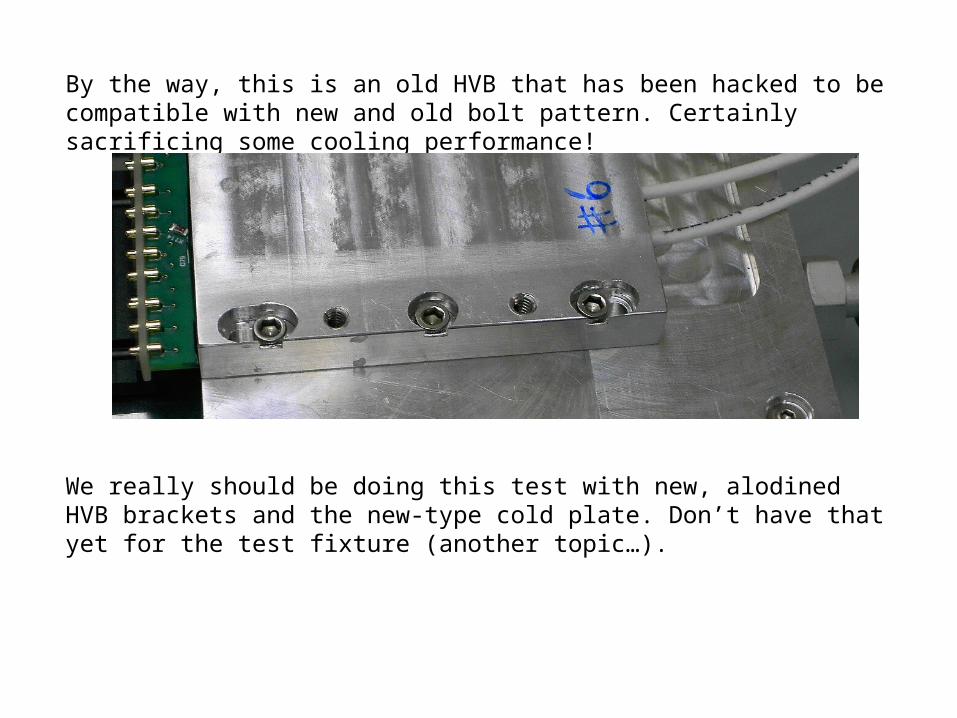
By the way, this is an old HVB that has been hacked to be compatible with new and old bolt pattern. Certainly sacrificing some cooling performance!
We really should be doing this test with new, alodined HVB brackets and the new-type cold plate. Don’t have that yet for the test fixture (another topic…).
UPDATE 12/12/2014
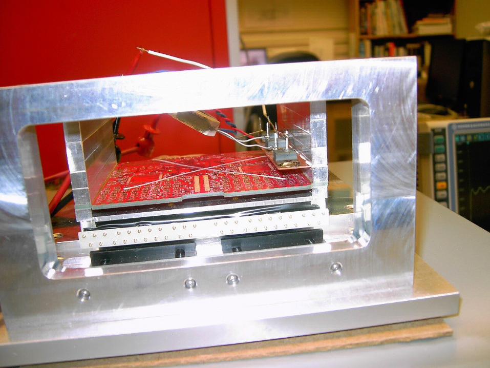
First reconfirmed ~same results as before
Then, switched to real carrier rev E, and relocated the heater slightly (it should be in “next” carrier board position for more accurate results, but wasn’t possible using the SCROD as a stand-in; also the SCROD couldn’t be put in place of bottom carrier board (connector conflicts with HVB bracket)).
Now, real carrier board, in bottom position, ~40W heater in next carrier board position.
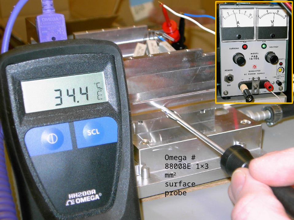
Omega # 88008E 1×3 mm2 surface probe
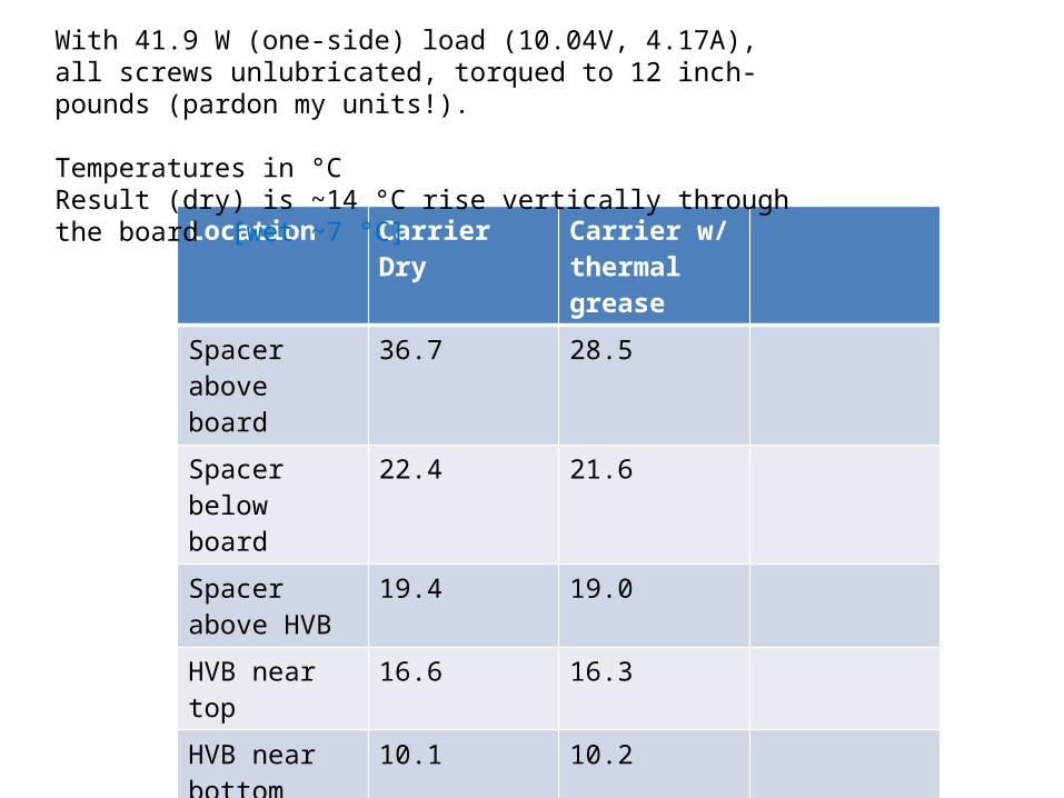
Location Carrier Dry Carrier w/ thermal grease
Spacer above board
36.7 28.5
Spacer below board
22.4 21.6
Spacer above HVB
19.4 19.0
HVB near top 16.6 16.3
HVB near bottom
10.1 10.2
Cold plate nearby
7.0 6.6
With 41.9 W (one-side) load (10.04V, 4.17A),all screws unlubricated, torqued to 12 inch-pounds (pardon my units!).
Temperatures in °CResult (dry) is ~14 °C rise vertically through the board [wet ~7 °C]