Embed Size (px)
Citation preview

Document Format Revision (5/1/09))
SCOPE OF WORK
PIPING SYSTEM UPGRADES
NJ Record Storage Center & Library for the Blind
West Trenton, Mercer County, N.J.
PROJECT NO. A1028-00
STATE OF NEW JERSEY Honorable Jon S. Corzine, Governor
DEPARTMENT OF THE TREASURY
R. David Rousseau, State Treasurer
DIVISION OF PROPERTY MANAGEMENT AND CONSTRUCTION
Steven Sutkin, Director
Richard Flodmand, Deputy Director
Raymond A. Arcario, Deputy Director
Date: December3, 2009

PROJECT NAME: Piping System Upgrades
PROJECT LOCATION: NJ Record Storage & Library for the Blind
PROJECT NO: A1028-00
DATE: December 3, 2009
PAGE 2
TABLE OF CONTENTS
SECTION PAGE
I. OBJECTIVE ...........................................................................................7
II. CONSULTANT QUALIFICATIONS ..................................................7
A. CONSULTANT & SUB-CONSULTANT PRE-QUALIFICATIONS
III. PROJECT BUDGET ..............................................................................7
A. CONSTRUCTION COST ESTIMATE (CCE)
B. CURRENT WORKING ESTIMATE (CWE)
C. COST ESTIMATING
D. CONSULTANT'S FEES
IV. PROJECT SCHEDULE .........................................................................9
A. SCOPE OF WORK DESIGN & CONSTRUCTION SCHEDULE
B. CONSULTANT'S PROPOSED DESIGN & CONSTRUCTION SCHEDULE
C. CONSULTANT DESIGN SCHEDULE
D. BID DOCUMENT CONSTRUCTION SCHEDULE
E. CONTRACTOR CONSTRUCTION PROGRESS SCHEDULE
V. PROJECT SITE LOCATION & TEAM MEMBERS ..................... 11
A. PROJECT SITE ADDRESS
B. PROJECT TEAM MEMBER DIRECTORY
1. DPMC Project Manager
2. Client Agency Representative
VI. PROJECT DEFINITION .................................................................... 12
A. BACKGROUND
B. DESCRIPTION OF THE BUILDING
C. DESCRIPTION OF THE HEATING & COOLING SYSTEM

PROJECT NAME: Piping System Upgrades
PROJECT LOCATION: NJ Record Storage & Library for the Blind
PROJECT NO: A1028-00
DATE: December 3, 2009
PAGE 3
VII. CONSULTANT DESIGN RESPONSIBILITIES ............................. 14
A. HEATING 7 COOLING SYSTEM REPAIR ANALYSIS
1. System Analysis
2. Piping
3. Hangers, Guides, and Expansion Fittings
4. Isolation Valves
5. Controls
6. Construction Schedule
7. System Repair Recommendation Report
8. System Repair Recommendation Presentation
B. HEATING & COOLING SYSTEM REPAIR DESIGN CRITERIA
1. Demolition Requirements
2. Interruption of Existing Utilities
3. Fire Protection Plan
4. Design Documents
5. Piping System Tests
C. GENERAL REQUIREMENTS
1. Contractor's Use of the Premises
D. GENERAL DESIGN OVERVIEW
1. Design Detail
2. Specification Format
E. PROJECT COMMENCEMENT
1. Project Directory
2. Site Access
3. Project Coordination
4. Existing Documentation
5. Scope of Work
6. Project Schedule
F. BUILDING & SITE INFORMATION
1. Building Classification
2. Building Block & Lot Number
3. Building Site Plan
4. Site Location Map
G. DESIGN MEETINGS & PRESENTATIONS
1. Design Meetings
2. Design Presentations
VIII. CONSULTANT CONSTRUCTION RESPONSIBILITIES ............ 23
A. GENERAL CONSTRUCTION ADMINISTRATION OVERVIEW
B. PRE-BID MEETING
C. BID OPENING

PROJECT NAME: Piping System Upgrades
PROJECT LOCATION: NJ Record Storage & Library for the Blind
PROJECT NO: A1028-00
DATE: December 3, 2009
PAGE 4
D. POST BID REVIEW MEETING, RECOMMENDATION FOR AWARD
1. Post Bid Review
2. Review meeting
3. Substitutions
4. Schedule
5. Performance
6. Superintendent
7. Letter of Recommendation
8. Conformed Drawings
E. DIRECTOR'S HEARING
F. CONSTRUCTION JOB MEETINGS, SCHEDULES, LOGS
1. Meetings
2. Schedules
3. Submittal Log
G. CONSTRUCTION SITE ADMINISTRATION SERVICES
H. SUB-CONSULTANT PARTICIPATION
I. DRAWINGS
1. Shop Drawings
2. As-Built & Record Set Drawings
J. CONSTRUCTION DEFICIENCY LIST
K. INSPECTIONS: SUBSTANTIAL & FINAL COMPLETION
L. CLOSE-OUT DOCUMENTS
M. CLOSE-OUT ACTIVITY TIME
N. TESTING, TRAINING, MANUALS, AND ATTIC STOCK
1. Testing
2. Training
3. Manuals
4. Attic Stock
O. CHANGE ORDERS
1. Consultant
2. Contractor
3. Recommendation for Award
4. Code Review
5. Cost Estimate
6. Time Extension
7. Submission
8. Meetings
9. Consultant Fee

PROJECT NAME: Piping System Upgrades
PROJECT LOCATION: NJ Record Storage & Library for the Blind
PROJECT NO: A1028-00
DATE: December 3, 2009
PAGE 5
IX. PERMITS & APPROVALS ................................................................ 34
A. REGULATORY AGENCY PERMITS
1. NJ Uniform Construction Code Permit
2. Other Regulatory Agency Approvals & Permits
3. Prior Approval Certification Letters
B. BARRIER FREE REQUIREMENTS
C. STATE INSURANCE APPROVAL
D. PUBLIC EMPLOYEES OCCUPATIONAL SAFETY & HEALTH PROGRAM
E. MULTI-BUILDING OR MULTI-SITE PERMITS
F. PERMIT MEETINGS
G. MANDATORY NOTIFICATIONS
H. CONSTRUCTION TRAILER PERMITS
I. SPECIAL INSPECTIONS
X. GENERAL REQUIREMENTS .......................................................... 39
A. SCOPE CHANGES
B. ERRORS & OMISSIONS
C. ENERGY INCENTIVE PROGRAM
D. AIR POLLUTION FROM ARCHITECTURAL COATINGS
XI. ALLOWANCES ................................................................................... 40
A. PERMIT ALLOWANCE
1. Permits
2. Permit Costs
3. Applications
4. Consultant Fee
XII. SUBMITTAL REQUIREMENTS ...................................................... 41
A. CONTRACT DELIVERABLES
B. CATALOG CUTS
C. PROJECT DOCUMENT BOOKLET
D. DESIGN DOCUMENT CHANGES
E. SINGLE-PRIME CONTRACT
XIII. SOW SIGNATURE APPROVAL SHEET ........................................ 43
XIV. CONTRACT DELIVERABLES ......................................................... 44

PROJECT NAME: Piping System Upgrades
PROJECT LOCATION: NJ Record Storage & Library for the Blind
PROJECT NO: A1028-00
DATE: December 3, 2009
PAGE 6
XV. EXHIBITS ............................................................................................. 50
A. SAMPLE PROJECT SCHEDULE FORMAT, 4 pages
B. PROJECT SITE PLAN
C. FORENSIC ANALYSIS & REPORT, 23 pages
D. BUILDING FLOOR PLAN
E. EXISTING HVAC PIPING PLAN WITH HIGHLIGHTED CHANGES

PROJECT NAME: Piping System Upgrades
PROJECT LOCATION: NJ Record Storage & Library for the Blind
PROJECT NO: A1028-00
DATE: December 3, 2009
PAGE 7
I. OBJECTIVE
The objective of this project is to upgrade various components of the heating and cooling piping
distribution system of the NJ Record Storage Center & Library for the Blind Building located in West
Trenton, NJ.
II. CONSULTANT QUALIFICATIONS
A. CONSULTANT & SUB-CONSULTANT PRE-QUALIFICATIONS
The Consultant shall be a firm pre-qualified with the Division of Property Management &
Construction (DPMC) in the P003 HVAC Engineering Discipline and have in-house capabilities or
Sub-Consultants pre-qualified with DPMC in all other Engineering and Specialty Disciplines
necessary to complete the project as described in this Scope of Work (SOW).
III. PROJECT BUDGET
A. CONSTRUCTION COST ESTIMATE (CCE)
The initial Construction Cost Estimate (CCE) for this project is $180,000.
The Consultant shall use their cost estimating experience to evaluate this SOW and provide in writing
an independent CCE for this project with their technical proposal. The Consultant shall provide a
detailed description identifying the development of the CCE.
B. CURRENT WORKING ESTIMATE (CWE)
The Current Working Estimate (CWE) for this project is $252,000.
The CWE includes the construction cost estimate and all consulting, permitting and administrative
fees.

PROJECT NAME: Piping System Upgrades
PROJECT LOCATION: NJ Record Storage & Library for the Blind
PROJECT NO: A1028-00
DATE: December 3, 2009
PAGE 8
The CWE is the Client Agency’s financial budget based on this project Scope of Work and shall not
be exceeded during the design and construction phases of the project unless DPMC approves the
change in Scope of Work through a Contract amendment.
C. COST ESTIMATING
All CCE under $750,000 may be prepared by the Consultant’s in-house staff or their Sub-Consultant’s
staff during each design phase of the project. However, if the CCE is $750,000 or larger, the
Consultant or Sub-Consultant providing the estimate must be pre-qualified with DPMC in the P025
Estimating/Cost Analysis Specialty Discipline.
All cost estimates shall be adjusted for regional location, site factors, construction phasing, premium
time, building use group, location of work within the building, temporary swing space, security issues,
and inflation factors based on the year in which the work is to be performed.
All cost estimates must be submitted on a DPMC-38 Project Cost Analysis form at each design phase
of the project with a detailed construction cost analysis in CSI format (2004 Edition) for all
appropriate divisions and sub-divisions. The Project Manager will provide cost figures for those items
which may be in addition to the CCE such as art inclusion, CM services, etc. and must be included as
part of the CWE. This cost analysis must be submitted for all projects regardless of the Construction
Cost Estimate amount.
D. CONSULTANT‟S FEES
The construction cost estimate for this project shall not be used as a basis for the Consultant’s design
and construction administration fees. The Consultant’s fees shall be based on the information
contained in this Scope of Work document and the observations made and/or the additional
information received during the pre-proposal meeting.

PROJECT NAME: Piping System Upgrades
PROJECT LOCATION: NJ Record Storage & Library for the Blind
PROJECT NO: A1028-00
DATE: December 3, 2009
PAGE 9
IV. PROJECT SCHEDULE
A. SCOPE OF WORK DESIGN & CONSTRUCTION SCHEDULE
The following schedule identifies the estimated design and construction phases for this project and the
estimated durations.
PROJECT PHASE ESTIMATED DURATION (Calendar Days)
1. Design Development Phase 50% (Minimum) 35
Project Team & DPMC Plan/Code Unit Review & Comment 14
2. Final Design Phase 100% 28
Project Team & DPMC Plan/Code Unit Review & Approval 14
3. Permit Application Phase 7
Issue Permit
4. Bid Phase 35
5. Award Phase 21
6. Construction Phase 120
B. CONSULTANT‟S PROPOSED DESIGN & CONSTRUCTION SCHEDULE
The Consultant shall submit a project design and construction bar chart schedule with their technical
proposal that is similar in format and detail to the schedule depicted in Exhibit „A‟. The bar chart
schedule developed by the Consultant shall reflect their recommended project phases, phase activities,
activity durations.
The Consultant shall estimate the duration of the project Close-Out Phase based on the anticipated
time required to complete each deliverable identified in Section XIV of this document entitled “Project
Close-Out Phase Contract Deliverables” and include this information in the bar chart schedule
submitted.

PROJECT NAME: Piping System Upgrades
PROJECT LOCATION: NJ Record Storage & Library for the Blind
PROJECT NO: A1028-00
DATE: December 3, 2009
PAGE 10
A written narrative shall also be included with the technical proposal explaining the schedule
submitted and the reasons why and how it can be completed in the time frame proposed by the
Consultant.
This schedule and narrative will be reviewed by the Consultant Selection Committee as part of the
evaluation process and will be assigned a score commensurate with clarity and comprehensiveness of
the submission.
C. CONSULTANT DESIGN SCHEDULE
The Project Manager will issue the Consultant’s approved project schedule at the first design kickoff
meeting. This schedule will be binding for the Consultant’s activities and will include the start and
completion dates for each design activity. The Consultant and Project Team members shall use this
schedule to ensure that all design milestone dates are being met for the project. The Consultant shall
update the schedule to reflect performance periodically (minimally at each design phase) for the
Project Team review and approval. Any recommendations for deviations from the approved design
schedule must be explained in detail as to the causes for the deviation(s) and impact to the schedule.
D. BID DOCUMENT CONSTRUCTION SCHEDULE
The Consultant shall include a construction schedule in Division 1 of the specification bid document.
This schedule shall contain, at minimum, the major activities and their durations for each trade
specified for the project. This schedule shall be in “bar chart” format and will be used by the
Contractors as an aid in determining their bid price. It shall reflect special sequencing or phased
construction requirements including, but not limited to: special hours for building access, weather
restrictions, imposed constraints caused by Client Agency program schedules, security needs, lead
times for materials and equipment, anticipated delivery dates for critical items, utility interruption and
shut-down constraints, and concurrent construction activities of other projects at the site and any other
item identified by the Consultant during the design phases of the project.
E. CONTRACTOR CONSTRUCTION PROGRESS SCHEDULE
The Contractor shall be responsible for preparing a coordinated combined progress schedule with the
Sub-Contractors after the award of the contract. This schedule shall meet all of the requirements
identified in the Consultant’s construction schedule. The construction schedule shall be completed in
accordance with the latest edition of the Instructions to Bidders and General Conditions entitled,
“Article 9, Construction Progress Schedule” (No CPM).

PROJECT NAME: Piping System Upgrades
PROJECT LOCATION: NJ Record Storage & Library for the Blind
PROJECT NO: A1028-00
DATE: December 3, 2009
PAGE 11
The Consultant must review and analyze this progress schedule and recommend approval/disapproval
to the Project Team until a satisfactory version is approved by the Project Team. The Project Team
must approve the baseline schedule prior to the start of construction and prior to the Contractor
submitting invoices for payment.
The Consultant shall note in Division 1 of the specification that the State will not accept the progress
schedule until it meets the project contract requirements and any delays to the start of the construction
work will be against the Contractor until the date of acceptance by the State.
The construction progress schedule shall be reviewed, approved, and updated by the Contractor of
schedule, Consultant, and Project Team members at each regularly scheduled construction job meeting
and the Consultant shall note the date and trade(s) responsible for project delays (as applicable).
V. PROJECT SITE LOCATION & TEAM MEMBERS
A. PROJECT SITE ADDRESS
The location of the project site is:
NJ Record Storage Center & Library for the Blind & Handicapped
2300 Stuyvesant Avenue
Trenton, NJ
See Exhibit „B‟ for the project site plan.
B. PROJECT TEAM MEMBER DIRECTORY
The following are the names, addresses, and phone numbers of the Project Team members.
1. DPMC Project Manager:
Name: David Lapidus, Project Manager
Address: Division Property Management & Construction
20 West State Street, 3rd
Floor
Trenton, NJ 08625
Phone No: (609) 984-9707
E-Mail No: [email protected]

PROJECT NAME: Piping System Upgrades
PROJECT LOCATION: NJ Record Storage & Library for the Blind
PROJECT NO: A1028-00
DATE: December 3, 2009
PAGE 12
2. Client Agency Representative:
Name: Gary Karr, Manager
Address: Division Property Management & Construction
20 West State Street, 3rd
Floor
Trenton, NJ 08625
Phone No: (609) 984-5933
E-Mail No: [email protected]
VI. PROJECT DEFINITION
A. BACKGROUND
The NJ Record Storage Center & Library for the Blind and Handicapped Building was constructed in
the early 1980’s and the heating and cooling is provided by 61 water source heat pumps which are
located throughout various areas of the building. The piping to and from each of the heat pumps is
Poly Vinyl Chloride (PVC) plastic, which is original to the building and has experienced numerous
failures which subjected the facility and valuable objects contained therein to potential water damage.
One recent failure occurred after normal business hours and the facility was forced to close for one
week while the cleanup operation was conducted at a cost of approximately $60,000.
In October 2008, DPMC hired a Consulting firm to conduct a study of the piping system and related
components in order to determine the cause of the failures, and make recommendations to mitigate the
problem(s). See Exhibit „C‟ for a copy of the final Forensic Analysis Report dated May 27, 2009. The
Consultant for this project shall review the report and prioritize the implementation of the
recommended repairs recognizing the cost-benefit and level of risk reduction achieved for each item.
The Consultant must also be aware that the recommended repairs for this project cannot exceed the
available project construction funding of $180,000.
B. DESCRIPTION OF THE BUILDING
The NJ Record Storage Center & Library for the Blind and Handicapped Building consists of a single
story structure of approximately 94,000 square feet, including a central core, office and work rooms,
storage areas, library and mechanical spaces. See Exhibit „D‟ for the building floor plan. The record
storage section of the building is used to archive large quantities of valuable State documents and the
library for the blind section is used to provide audio discs and Braille books for distribution to the
State’s visually impaired.

PROJECT NAME: Piping System Upgrades
PROJECT LOCATION: NJ Record Storage & Library for the Blind
PROJECT NO: A1028-00
DATE: December 3, 2009
PAGE 13
C. DESCRIPTION OF THE HEATING & COOLING SYSTEM
The building was constructed in the early 1980’s and the existing systems are now approximately 28
years old. The majority of the mechanical equipment appears to be in fair operational condition,
though some of the heat pumps have been replaced. The heat pump piping within the mechanical room
and out to the fluid cooler is black steel pipe. The heat pump water loop system beyond the mechanical
room appears to be a mixture of schedule 40 and schedule 80 PVC pipe. Recently many of the
schedule 40 portions of the piping loop have experienced failures and in many visible areas the
schedule 40 piping is in poor condition. The recent piping failures have resulted in leaks and damage
throughout the building.
The existing heating and cooling system is a water source heat pump arrangement consisting of a
central mechanical space which houses the heat pump water supply loop pumps, electric boiler and
storage tank. The habitable spaces throughout the building are served by horizontal heat pumps
mounted throughout the hung ceiling spaces. Two roof mount heat recovery units with reheat features
provide ventilation for the office and other non-storage areas, by circulating outside air into the ceiling
plenums. The archive storage areas at the rear of the building are served by roof mounted water source
heat pumps. A three cell fluid cooler on grade provides the heat rejection as required to keep the water
loop below the designated temperature. Conversely, the electric boiler will add heat to the loop as
required in the winter to maintain a minimum loop temperature. The heat pump loop temperature is
designed for a nominal range between 70 F and 90 F. Since the original 1980 installation various
pieces of equipment have been either repaired or replaced and appear to be in acceptable condition,
with the exception of various piping loop sections. See Exhibit „E‟ for a schematic drawing of the
heating and cooling system piping plan. Note that full size drawings will be made available to the
design Consultant.
The original heat pumps were manufactured by Command-Aire which was later purchased and
absorbed by the Trane Company. All of the replacements have been made with Trane Units, which is
the same product line as the original. The 61 heat pumps range in size from ¾ Ton to 5 Tons. Each
heat pump is connected to the piping system with a set of braided stainless steel flexible hoses, the
majority of the units are made with nominal 1” connections, however, there are some units with ¾ “
connections as well as some with 1¼ “ connections. After the hoses, there is additional piping and
valves that are referred to as the “Trim” package on the unit

PROJECT NAME: Piping System Upgrades
PROJECT LOCATION: NJ Record Storage & Library for the Blind
PROJECT NO: A1028-00
DATE: December 3, 2009
PAGE 14
VII. CONSULTANT DESIGN RESPONSIBILITIES
A. HEATING & COOLING SYSTEM REPAIR ANALYSIS
1. System Analysis:
DPMC is recommending that the Consultant consider the repairs recommended in Option 1 of the
Forensic Analysis Report. Since the recommended repairs and related costs are beyond the available
funding for this project, the Consultant shall analyze the condition of the piping distribution system
and prioritize the implementation of the repairs based on the cost-benefit and level of risk reduction
achieved for each item. Special priority shall be given to system upgrades in the critical areas of the
building such as the archive area and library storage area.
See Exhibit „C‟ for the Forensic Analysis Report. The total construction cost for the prioritized items
shall not exceed the available project construction funding of $180,000.
2. System Piping:
It should be noted that all system piping failures have only occurred in the smaller branch piping and it
is recommended that only the piping section sizes up to 1¼” be considered for replacement. See
Exhibit „E‟ for the pipe sections recommended for repairs highlighted in yellow.
The Consultant shall also review replacing the plastic pipe with copper tubing. A cost analysis shall be
made of the two piping materials considering material and installation costs and a recommendation
shall be made of the piping to be used for this project. Consideration shall be given to bidding one of
the materials as an Alternate.
3. Hangers, Guides, and Expansion Fittings:
Conduct a visual inspection of the piping system using the report as a guide, and recommend the
additional pipe hangers, anchors, guides, and expansion fittings to be added in the areas of the piping
system with greatest potential for failure.
Determine appropriate locations for the expansion joints so they will absorb axial cyclical pipe
movement resulting from thermal expansion, contraction, and vibration. Also determine where to
provide factory-built or field-fabricated guides to restrain the lateral pipe motion and direct the axial
pipe movement into the expansion joints.
Determine the appropriate location of the pipe hangers to prevent sagging of the piping and prevent
excessive forces, moments, and stresses from being imposed on any equipment and support system.

PROJECT NAME: Piping System Upgrades
PROJECT LOCATION: NJ Record Storage & Library for the Blind
PROJECT NO: A1028-00
DATE: December 3, 2009
PAGE 15
4. Isolation Valves:
Approximately one half of the heat pumps do not have isolation valves. Review and recommend the
heat pumps that should have isolation valves installed on them based on their age, physical condition,
and the critical nature of the area they serve.
5. Controls:
Heat pump controls shall be modified so they shut down on loss of flow. Conduct an analysis and
recommend the heat pumps that should have shut down control switches based their age, physical
condition, and the critical nature of the area they serve.
6. Construction Schedule:
Analyze and recommend the approach for phased construction of the piping system repairs
considering that the system will need to be shut down and drained to replace the heat pump isolation
valves, piping sections, expansion fittings, etc.
Seasonal considerations, allowable time for system shutdown, temporary bypass loops to allow shut
down of piping sections, premium time requirements, safety procedures and methods to protect the
building’s library and archive materials during construction, manpower requirements to optimize the
amount of work that can be accomplished during the piping system shutdown, and any other critical
issues shall be analyzed. A preliminary schedule shall be provided for the recommended upgrades to
the piping system.
7. System Repair Recommendation Report:
Provide 6 copies of a preliminary report identifying the prioritized repairs recommended for the
heating and cooling system and related components of the NJ Record Storage & Library for the Blind
Building to the Project Team. The document shall have a table of contents itemizing the sections
contained in the document and their related page numbers. An Executive Summary shall be included
that provides the overall objective of the project and the justifications for the system repairs
recommended in the report. Each recommendation shall have a cost estimate for reference.
All supporting documentation such as the systems survey information collected, calculations,
photographs, drawings, catalog cuts, cost analysis data, correspondence, meeting minutes, and any
other data collected shall be included in the report appendix for reference.
All cost data shall be in sufficient detail for each related division of the new CSI 2004 format and shall
be summarized on the DPMC 38 Cost Analysis form
Also provide a preliminary project construction schedule for the recommendations made.

PROJECT NAME: Piping System Upgrades
PROJECT LOCATION: NJ Record Storage & Library for the Blind
PROJECT NO: A1028-00
DATE: December 3, 2009
PAGE 16
8. System Repair Recommendation Presentation:
An oral presentation shall be made to the Project Team describing the recommendations proposed for
the heating and cooling system repairs with backup justifications. The Consultant may not proceed
with the design phase of the project until the Project Team has reviewed the report and approved the
recommendations for this project.
Note that 6 copies of the final approved report shall be provided to the Project Manager that has been
edited to reflect the piping system repairs approved, the project construction cost, and schedule.
B. HEATING & COOLING SYSTEM REPAIR DESIGN CRITERIA
This section of the scope of work is intended to describe the minimum amount of information to be
included in the design documents for this project. It is not to be considered all inclusive and the final
design criteria shall be determined by the Consultant based on their experience with projects similar in
size and scope.
1. Demolition Requirements:
The design documents shall state that all piping sections and related components that are removed
shall be disposed by the Contractor in a dumpster located in an area on site approved by the Client
Agency. Scrap materials may not be stored in the building.
Indicate the location and dimensioned details for any temporary construction partition plastic barriers
for dust and dirt containment, and details of special protective covers for equipment and stored library
and archived media. Describe the acceptable standards of cleanliness that the Contractor must meet
each workday in the construction area and other public areas of the building (if appropriate).
Issues such as noise & dust control, protection of equipment and interior finishes, fire safety measures,
and procedures for the security of valuable archived materials and office equipment located in the
construction areas must be established and included in the design documents.
2. Interruption of Existing Service:
The design documents shall inform the Contractor that special consideration must taken when shutting
down branch sections of the heating and cooling system to repair the piping and related components. A
preliminary schedule and special construction requirements must be submitted by the Contractor at the
bi-weekly job meetings so the information may be reviewed and approved by the Consultant and
Project Team prior to the work.

PROJECT NAME: Piping System Upgrades
PROJECT LOCATION: NJ Record Storage & Library for the Blind
PROJECT NO: A1028-00
DATE: December 3, 2009
PAGE 17
The special construction requirements to address in the design documents shall include, but not be
limited to seasonal considerations and temporary portable heaters if appropriate, identify the section of
branch piping and components to be repaired and the estimated construction duration, provisions for
temporary bypass loops to allow shut down of branch piping sections to be repaired and allow the
main system to still operate, access issues to the piping sections and requirements for special
scaffolding and temporary relocation of building materials located on the floor, premium time
requirements, manpower requirements to optimize the amount of work that can be accomplished
during the branch piping section shutdown, temporary utility shutdown coordination requirements, and
any other critical item not identified here.
3. Fire Protection Plan:
Address any fire protection requirements during the demolition and repairs to the heating and cooling
piping distribution system and related components. Language shall be included in the design
documents that states any acetylene, welding, brazing, and soldering equipment, or other potential
source of fire ignition cannot be used on the construction site until a fire watch program has been
submitted by the Contractor and approved by the Consultant and Project Team members.
4. Design Documents:
A fully engineered design of the new heating and cooling piping system shall be provided by the
Consultant. The design shall include, but not be limited to a scaled layout of the complete heating and
cooling piping system and all related system components as they are installed in the building. The
drawing shall indicate the branch piping sections and related components that are to be replaced,
repaired, or installed new and their location in the system. Riser diagrams shall be included with a
table that will summarize the size, quantity, rating, and other pertinent engineering information for
each new system component to be installed.
Details shall be included showing the approved method to install each item as per the manufacturers
recommendations. The specification shall indicate the name of desired manufacturers and three
alternate manufacturers for all new system components to be installed.
5. Piping System Tests:
Develop detailed piping system test requirements and ensure that they are incorporated into the
specifications so that the Contractors may budget the proper amount of time for these tests in their bid
proposals. The design specification testing information shall include, but not be limited to the
following information: the purpose of the test, required personnel, tools, and instruments needed to
perform the tests, design information pertinent to the equipment or system being tested, equipment
description, detailed test sequence, test pressures and durations, special instructions or warnings,
expected results, and sample strategies.

PROJECT NAME: Piping System Upgrades
PROJECT LOCATION: NJ Record Storage & Library for the Blind
PROJECT NO: A1028-00
DATE: December 3, 2009
PAGE 18
All appropriate approval authorities and/or Agencies shall observe the tests and the data shall be
reviewed and approved by the Consultant.
The Contractor shall provide a certificate testifying that the system was satisfactorily tested as
specified and passed.
The certification shall also provide the following information:
Identification of system tested and references to the specific equipment connected to the system.
Date tested.
Test pressure and duration of test.
All recorded test data.
Media used for the testing.
List of necessary repairs made before system passed the test.
Signature of the Contractor.
Signature of the Inspector.
Other data as required by the Consultant.
Three (3) copies of the test results shall be forwarded to the Project Manager for distribution.
C. GENERAL REQUIREMENTS
1. Contractor‟s Use of the Premises:
Develop a “Contractor’s Use of the Premises” directive with the Project Team that will identify any
special policies, procedures, security requirements, etc. that must be observed by the Contractors
during all work conducted at the facility and include this information in Division 1 of the specification.
Develop procedures for personnel to access the project site and construction areas, and provide the
names and phone numbers of approved escorts when needed.

PROJECT NAME: Piping System Upgrades
PROJECT LOCATION: NJ Record Storage & Library for the Blind
PROJECT NO: A1028-00
DATE: December 3, 2009
PAGE 19
D. GENERAL DESIGN OVERVIEW
1. Design Detail:
Section VII of this Scope of Work is intended as a guide for the Consultant to understand the overall
basic design requirements of the project and is not intended to identify each specific design component
related to code and construction items. The Consultant shall provide those details during the design
phase of the project ensuring that they are in compliance with all applicable codes, regulating
authorities, and the guidelines established in the DPMC Procedures for Architects and Engineers
Manual.
The Consultant shall understand that construction documents submitted to DPMC shall go beyond the
basic requirements set forth by the current copy of the Uniform Construction Code NJAC 5:23-
2.15(e). Drawings and specifications shall provide detail beyond that required to merely show the
nature and character of the work to be performed. The construction documents shall provide sufficient
information and detail to illustrate, describe and clearly delineate the design intent of the Consultant
and enable all Contractors to uniformly bid the project.
The Consultant shall ensure that all of the design items described in this scope of work are addressed
and included in the project drawings and specification sections where appropriate.
It shall be the Consultant’s responsibility to provide all of the design elements for this project. Under
no circumstance may they delegate the responsibility of the design; or portions thereof, to the
Contractor unless specifically allowed in this Scope of Work.
2. Specification Format:
The Consultant shall ensure that the project design specifications are formatted in the revised and
expanded version of the Construction Specifications Institute (CSI) format entitled “Master Format
2004 Edition: Numbers and Titles.”
The Consultant shall review all of the CSI Master Format 2004 specification sections listed and
remove those that do not apply and edit those that remain so they are consistent and specific to this
project scope of work.

PROJECT NAME: Piping System Upgrades
PROJECT LOCATION: NJ Record Storage & Library for the Blind
PROJECT NO: A1028-00
DATE: December 3, 2009
PAGE 20
E. PROJECT COMMENCEMENT
A pre-design meeting shall be scheduled with the Consultant and the Project Team members at the
commencement of the project to obtain and/or coordinate the following information:
1. Project Directory:
Develop a project directory that identifies the name and phone number of key designated
representatives who may be contacted during the design and construction phases of this project.
2. Site Access:
Develop procedures to access the project site and provide the names and phone numbers of approved
escorts when needed. Obtain copies of special security and policy procedures that must be followed
during all work conducted at the facility and include this information in Division 1 of the specification.
3. Project Coordination:
Review and become familiar with any current and/or future projects at the site that may impact the
design, construction, and scheduling requirements of this project. Incorporate all appropriate
information and coordination requirements in Division 1 of the specification.
4. Existing Documentation:
Obtain and review all available facility documentation that is related to this project such as reports,
studies, surveys, equipment manuals, as-built drawings, maintenance records, utility energy data, etc.
The State does not attest to the accuracy of the information provided and accepts no responsibility for
the consequences of errors by the use of any information and material contained in the documentation
provided. It shall be the responsibility of the Consultant to verify the contents and assume full
responsibility for any determination or conclusion drawn from the material used. If the information
provided is insufficient, the Consultant shall take the appropriate actions necessary to obtain the
additional information required for the project at no additional cost to the State.
All documentation shall be returned to the provider at the completion of the project.

PROJECT NAME: Piping System Upgrades
PROJECT LOCATION: NJ Record Storage & Library for the Blind
PROJECT NO: A1028-00
DATE: December 3, 2009
PAGE 21
5. Scope of Work:
Review the design and construction administration responsibilities and the submission requirements
identified in this Scope of Work with the Project Team members. Items such as: contract
deliverables, special sequencing or phased construction requirements, special hours for construction
based on Client Agency programs or building occupancy, security needs, delivery dates of critical and
long lead items, utility interruptions or shut down constraints for tie-ins, weather restrictions, and
coordination with other project construction activities at the site shall be addressed.
This information and all general administrative information; including a narrative summary of the
work for this project, shall be included in Division 1 of the specification. The Consultant shall assure
that there are no conflicts between the information contained in Division 1 of the specification and the
DPMC General Conditions.
6. Project Schedule:
Review and update the project design and construction schedule with the Project Team members.
F. BUILDING & SITE INFORMATION
The following information shall be included in the project design documents.
1. Building Classification:
Provide the building Use Group Classification and Construction Type on the appropriate design
drawing.
2. Building Block & Lot Number:
Provide the site Block and Lot Number on the appropriate design drawing.
3. Building Site Plan:
Only when the project scope involves site work, or when the design triggers code issues that require
site information to show code compliance, shall a site plan be provided that is drawn in accordance
with an accurate boundary line survey.

PROJECT NAME: Piping System Upgrades
PROJECT LOCATION: NJ Record Storage & Library for the Blind
PROJECT NO: A1028-00
DATE: December 3, 2009
PAGE 22
The site plan shall include but not be limited to the following as may be applicable.
The size and location of new and existing buildings and additions as well as other structures.
The distance between buildings and structures and to lot lines.
Established and new site grades and contours as well as building finished floor elevations.
New and existing site utilities, site vehicular and pedestrian roads, walkways and parking areas.
4. Site Location Map:
Provide a site location map on the drawing cover sheet that identifies the vehicular travel routes from
major roadways to the project construction site and the approved access roads to the Contractor’s
worksite staging area.
G. DESIGN MEETINGS & PRESENTATIONS
1. Design Meetings:
Conduct the appropriate number of review meetings with the Project Team members during each
design phase of the project so they may determine if the project meets their requirements, question any
aspect of the contract deliverables, and make changes where appropriate. The Consultant shall
describe the philosophy and process used in the development of the design criteria and the various
alternatives considered to meet the project objectives. Selected studies, sketches, cost estimates,
schedules, and other relevant information shall be presented to support the design solutions proposed.
Special considerations shall also be addressed such as: Contractor site access limitations, utility
shutdowns and switchover coordination, phased construction and schedule requirements, security
restrictions, available swing space, material and equipment delivery dates, etc.
It shall also be the responsibility of the Consultant to arrange and require all critical Sub-Consultants
to be in attendance at the design review meetings.
Record the minutes of each design meeting and distribute within seven (7) calendar days to all
attendees and those persons specified to be on the distribution list by the Project Manager.
2. Design Presentations:
The minimum number of design presentations required for each phase of this project is identified
below for reference:
Design Development Phase: One (1) oral presentation at phase completion.
Final Design Phase: One (1) oral presentation at phase completion.

PROJECT NAME: Piping System Upgrades
PROJECT LOCATION: NJ Record Storage & Library for the Blind
PROJECT NO: A1028-00
DATE: December 3, 2009
PAGE 23
VIII.CONSULTANT CONSTRUCTION RESPONSIBILITIES
A. GENERAL CONSTRUCTION ADMINISTRATION OVERVIEW
This section of the Scope of Work is intended as a guide for the Consultant to understand their overall
basic construction administration responsibilities for the project and does not attempt to identify each
specific activity or deliverable required during this phase. The Consultant shall obtain that information
from the current publication of the DPMC Procedures for Architects and Engineers Manual and any
additional information provided during the Consultant Selection Process.
B. PRE-BID MEETING
The Consultant shall attend, chair, record and distribute minutes of the Contractor pre-bid meetings.
When bidders ask questions that may affect the bid price of the project, the Consultant shall develop a
Bulletin(s) to clarify the bid documents in the format described in the Procedures for Architects and
Engineers Manual, Section 9.2 entitled “Bulletins.” These Bulletins must be sent to DPMC at least
seven (7) calendar days prior to the bid opening date. DPMC will then distribute the document to all
bidders.
C. BID OPENING
The Consultant must attend the bid opening held at the designated location.
In the event that the construction bids received exceed the Consultant’s approved final cost estimate by
5% or more, the Consultant shall redesign and/or set up sufficient approved alternate designs, plans
and specifications for the project work, to secure a bid that will come within the allocation specified
by the State without impacting the programmatic requirements of the project. Such redesign work and
changes to plans, including reproduction costs for submission in order to obtain final approval and
permits, shall be undertaken by the Consultant at no additional cost to the State.
D. POST BID REVIEW MEETING, RECOMMENDATION FOR AWARD
The Consultant; in conjunction with the Project Manager, shall review the bid proposals submitted by
the various Contractors to determine the low responsible bid for the project. The Consultant; in
conjunction with the Project Manager, shall develop a post bid questionnaire based on the
requirements below and schedule a post bid review meeting with the Contractor’s representative to
review the construction costs and schedule, staffing, and other pertinent information to ensure they
understand the Scope of the Work and that their bid proposal is complete and inclusive of all required
to deliver the project in strict accordance with the plans and specifications.

PROJECT NAME: Piping System Upgrades
PROJECT LOCATION: NJ Record Storage & Library for the Blind
PROJECT NO: A1028-00
DATE: December 3, 2009
PAGE 24
1. Post Bid Review:
Review the project bid proposals including the alternates, unit prices, and allowances within seven (7)
calendar days from the bid due date. Provide a bid tabulation matrix comparing all bids submitted and
make a statement about the high, low, and average bids received. Include a comparison of the
submitted bids to the approved current construction cost estimate. When applicable, provide an
analysis with supporting data, detailing why the bids did not meet the construction cost estimate.
2. Review Meeting:
Arrange a meeting with the apparent low bid Contractor to discuss their bid proposal and other issues
regarding the award of the contract. Remind the Contractor that this is a Lump Sum bid. Request the
Contractor to confirm that their bid proposal does not contain errors. Review and confirm Alternate
pricing and Unit pricing and document acceptance or rejection as appropriate.
Comment on all omissions, qualifications and unsolicited statements appearing in the proposals.
Review any special circumstances of the project. Ensure the Contractor’s signature appears on all post
bid review documents.
3. Substitutions:
Inquire about any potential substitutions being contemplated by the Contractor and advise them of the
State’s guidelines for the approval of substitutions and the documentation required. Review the
deadline and advise the Contractor that partial submissions are not acceptable. Submission after the
deadline may be rejected by the State.
Equal substitutions that are proposed by the Contractor that are of lesser value must have a credit
change order attached with the submittal (See Article 4 of the General Conditions). The State has the
right to reject the submission if there is no agreement on the proposed credit. Contractor will be
responsible to submit a specified item.
4. Schedule:
Confirm that the Contractor is aware of the number of calendar days listed in the contract documents
for the project duration and that the Contractor’s bid includes compliance with the schedule duration
and completion dates. Particular attention shall be given to special working conditions, long lead items
and projected delivery dates, etc. Review project milestones (if applicable). This could give an
indication of Contractor performance, but not allow a rejection of the bid.
Review the submittal timeframes per the Contract documents. Ask the Contractor to identify what
products will take over twenty-eight (28) calendar days to deliver from the point of submittal approval.

PROJECT NAME: Piping System Upgrades
PROJECT LOCATION: NJ Record Storage & Library for the Blind
PROJECT NO: A1028-00
DATE: December 3, 2009
PAGE 25
5. Performance:
Investigate the past performance of Contractor by contacting Architects and owners (generally three of
each) that were listed in their DPMC pre-qualification package and other references that may have
been provided. Inquire how the Contractor performed with workmanship, schedule, project
management, change orders, cooperation, paper work, etc.
6. Superintendent:
Remind the Contractor that a full-time non-working superintendent is required per the General
Conditions, who must be responsible to address Contract issues. (Article 4.3.2.).
7. Letter of Recommendation:
The Consultant shall prepare a Letter of Recommendation for contract award to Contractor submitting
the low responsible bid within three (3) calendar days from the post bid review meeting. The
document shall contain the project title, DPMC project number, bid due date and expiration date of the
proposal. It shall include a detailed narrative describing each post bid meeting agenda item identified
above and a recommendation to award the contract to the apparent low bid Contractor based on the
information obtained during that meeting. Describe any acceptance or rejection of Alternate pricing
and Unit pricing.
Comment on any discussion with the Contractor that provides a sense of their understanding of the
project and any special difficulties that they see, and how they might approach those problems.
Attach all minutes of the Post bid meeting and any other relevant correspondence with the Letter of
Recommendation and submit them to the Project Manager.
8. Conformed Drawings:
The Consultant shall prepare and distribute two (2) sets of drawings stamped “Conformed Drawings”
to the Project Manager that reflect all Bulletins and/or required changes, additions, and deletions to the
pertinent drawings within twenty-eight (28) calendar days of the construction contract award date.
Any changes made in Bulletins, meeting minutes, post bid review requirements shall also be reflected
in the specification.

PROJECT NAME: Piping System Upgrades
PROJECT LOCATION: NJ Record Storage & Library for the Blind
PROJECT NO: A1028-00
DATE: December 3, 2009
PAGE 26
E. DIRECTOR‟S HEARING
The Consultant must attend any Director’s hearing(s) if a Contractor submits a bid protest. The
Consultant shall be present to interpret the intent of the design documents and answer any technical
questions that may result from the meeting. In cases where the bid protest is upheld, the Consultant
shall submit a new “Letter of Recommendation” for contract award. The hours required to attend the
potential hearings and to document the findings shall be estimated by the Consultant and the costs will
be included in the base bid of their fee proposal.
F. CONSTRUCTION JOB MEETINGS, SCHEDULES, LOGS
The Consultant shall conduct all of the construction job meetings in accordance with the procedures
identified in the A/E manual and those listed below.
1. Meetings:
The Consultant and Sub-Consultant(s) shall attend the pre-construction meeting and all construction
job meetings during the construction phase of the project. The Consultant shall chair the meeting,
transcribe and distribute the job-meeting minutes for every job meeting to all attendees and to those
persons specified to be on the distribution list by the Project Manager. The Agenda for the meeting
shall include, but not be limited to the items identified in the Procedures for Architects and Engineers
Manual, Section 10.3.1, entitled “Agenda.”
Also, the Consultant is responsible for the preparation and distribution of minutes within seven (7)
calendar days of the meeting. The format to be used for the minutes shall comply with those identified
in the “Procedures for Architects and Engineers Manual,” Section 10.3.4, entitled, “Format of
Minutes.” All meeting minutes are to have an “action” column indicating the party that is responsible
for the action indicated and a deadline to accomplish the assigned task. These tasks must be reviewed
at each job progress meeting until it is completed and the completion date of each task shall be noted
in the minutes of the meeting following the task completion.
2. Schedules:
The Consultant; with the input from the Client Agency Representative and Project Manager, shall
review and recommend approval of the project construction schedule prepared by the Contractor. The
schedule shall identify all necessary start and completion dates of construction, construction activities,
submittal process activities, material deliveries and other milestones required to give a complete
review of the project.
The Consultant shall record any schedule delays, the party responsible for the delay, the schedule
activity affected, and the original and new date for reference.

PROJECT NAME: Piping System Upgrades
PROJECT LOCATION: NJ Record Storage & Library for the Blind
PROJECT NO: A1028-00
DATE: December 3, 2009
PAGE 27
The Consultant shall ensure that the Contractor provides a two (2) week “look ahead” construction
schedule based upon the current monthly updated schedule as approved at the bi-weekly job meetings
and that identifies the daily planned activities for that period. This Contractor requirement must also
be included in Division 1 of the specification for reference.
3. Submittal Log:
The Consultant shall develop and implement a submittal log that will identify all of the required
project submittals as identified in the design specification. The dates of submission shall be
determined and approved by all affected parties during the pre-construction meeting.
Examples of the submissions to be reviewed and approved by the Consultant and Sub-Consultant (if
required) include: shop drawings, change orders, Request for Information (RFI), equipment and
material catalog cuts, spec sheets, product data sheets, MSDS material safety data sheets, specification
procedures, color charts, material samples, mock-ups, etc. The submittal review process must be
conducted at each job progress meeting and shall include the Consultant, Sub-Consultant, Contractor,
Project Manager, and designated representatives of the Client Agency.
The Consultant shall provide an updated submittal log at each job meeting that highlights all of the
required submissions that are behind schedule during the construction phase of the project.
G. CONSTRUCTION SITE ADMINISTRATION SERVICES
The Consultant and Sub-Consultant(s) shall provide construction site administration services during
the duration of the project. The Consultant and Sub-Consultant(s) do not necessarily have to be on site
concurrently if there are no critical activities taking place that require the Sub-Consultant’s
participation.
The services required shall include, but not be limited to; field observations sufficient to verify the
quality and progress of construction work, conformance and compliance with the contract documents,
or to attend/chair meetings as may be required by the Project Manager to resolve special issues.
A field observation visit may be conducted in conjunction with regularly scheduled construction job
meetings, depending on the progress of work. The Consultant and their Sub-Consultant(s) shall
submit a field observation report for each site inspection to the Project Manager. Also, they shall
conduct inspections during major construction activities including, but not limited to the following
examples: concrete pours, steel and truss installations, code inspections, final testing of systems,
achievement of each major milestone required on the construction schedule, and requests from the
Project Manager. The assignment of a full time on-site Sub-Consultant does not relieve the Consultant
of their site visit obligation.

PROJECT NAME: Piping System Upgrades
PROJECT LOCATION: NJ Record Storage & Library for the Blind
PROJECT NO: A1028-00
DATE: December 3, 2009
PAGE 28
The Consultant shall refer to Section XIV. Contract Deliverables of this Scope of Work subsection
entitled “Construction Phase” to determine the extent of services and deliverables required during this
phase of the project.
H. SUB-CONSULTANT PARTICIPATION
It is the responsibility of the Consultant to ensure that they have provided adequate hours and/or time
allotted in their technical proposal so that their Sub-Consultants may participate in all appropriate
phases and activities of this project or whenever requested by the Project Manager. This includes the
pre-proposal site visit and the various design meetings and construction job meetings, site visits, and
close-out activities described in this Scope of Work. Field observation reports and/or meeting minutes
are required to be submitted to the Project Manager within seven (7) calendar days of the site visit or
meeting. All costs associated with such services shall be included in the base bid of the Consultant’s
fee proposal.
I. DRAWINGS
1. Shop Drawings:
Each Contractor shall review the specifications and determine the numbers and nature of each shop
drawing submittal. Five (5) sets of the documents shall be submitted with reference made to the
appropriate section of the specification. The Consultant shall review the Contractor’s shop drawing
submissions for conformity with the construction documents within fourteen (14) calendar days of
receipt. The Consultant shall return each shop drawing submittal stamped with the appropriate action,
i.e. “Approved”, “Approved as Noted”, “Approved as Noted Resubmit for Records”, “Rejected”, etc.
2. As-Built & Record Set Drawings:
The Contractor(s) shall keep the contract drawings up to date at all times during construction and upon
completion of the project, submit their AS-BUILT drawings to the Consultant with the Contractor(s)
certification as to the accuracy of the information prior to final payment. All AS-BUILT drawings
submitted shall be entitled AS-BUILT above the title block and dated. The Consultant shall review the
Contractor(s) AS-BUILT drawings at each job progress meeting to ensure that they are up to date. Any
deficiencies shall be noted in the progress meeting minutes.
The Consultant shall acknowledge acceptance of the AS-BUILT drawings by signing a transmittal
indicating they have reviewed them and that they reflect the AS-BUILT conditions as they exist.

PROJECT NAME: Piping System Upgrades
PROJECT LOCATION: NJ Record Storage & Library for the Blind
PROJECT NO: A1028-00
DATE: December 3, 2009
PAGE 29
Upon receipt of the AS-BUILT drawings from the Contractor(s), The Consultant shall obtain the
original mylars from DPMC and transfer the AS-BUILT conditions to the original full sized signed
mylars to reflect RECORD conditions within twenty-eight (28) calendar days of receipt of the AS-
BUILT information.
The Consultant shall note the following statement on the original RECORD-SET drawings. “The AS-
BUILT information added to this drawing(s) has been supplied by the Contractor(s). The (Architect)
(Engineer) does not assume the responsibility for its accuracy other than conformity with the design
concept and general adequacy of the AS-BUILT information to the best of the (Architect’s)
(Engineer’s) knowledge.”
Upon completion, The Consultant shall deliver the RECORD-SET original mylars to DPMC who will
acknowledge their receipt in writing. This hard copy set of drawings and three (3) sets of current
release AUTO CAD discs shall be submitted to DPMC and the discs shall contain all AS-BUILT
drawings in both “.dwg” (native file format for AUTO CAD) and “.tif” (Tagged Image File) file
formats.
J. CONSTRUCTION DEFICIENCY LIST
The Consultant shall prepare, maintain and continuously distribute an on-going deficiency list to the
Contractor, Project Manager, and Client Agency Representative during the construction phase of the
project. This list shall be separate correspondence from the field observation reports and shall not be
considered as a punch list.
K. INSPECTIONS: SUBSTANTIAL & FINAL COMPLETION
The Consultant and their Sub-Consultant(s) accompanied by the Project Manager, Code Inspection
Group, Client Agency Representative and Contractor shall conduct site inspections to determine the
dates of substantial and final completion. The Project Manager will issue the only recognized official
notice of substantial completion. The Consultant shall prepare and distribute the coordinated punch
list, written warranties and other related DPMC forms and documents, supplied by the Contractor, to
the Project Manager for review and certification of final contract acceptance.
If applicable, the punch list shall include a list of attic stock and spare parts.

PROJECT NAME: Piping System Upgrades
PROJECT LOCATION: NJ Record Storage & Library for the Blind
PROJECT NO: A1028-00
DATE: December 3, 2009
PAGE 30
L. CLOSE-OUT DOCUMENTS
The Consultant shall review all project close-out documents as submitted by the Contractors to ensure
that they comply with the requirements listed in the “Procedure for Architects and Engineers’
Manual.” The Consultant shall forward the package to the Project Manager within twenty-eight (28)
calendar days from the date the Certificate of Occupancy/Certificate of Approval is issued. The
Consultant shall also submit a letter certifying that the project was completed in accordance with the
contract documents, etc.
M. CLOSE-OUT ACTIVITY TIME
The Consultant shall provide all activities and deliverables associated with the “Close-Out Phase” of
this project as part of their Lump Sum base bid. The Consultant and/or Sub-Consultant(s) may not use
this time for additional job meetings or extended administrative services during the Construction Phase
of the project.
N. TESTING, TRAINING, MANUALS, AND ATTIC STOCK
The Consultant shall ensure that all equipment testing, training sessions and equipment manuals
required for this project comply with the requirements identified below.
1. Testing:
All equipment and product testing conducted during the course of construction is the responsibility of
the Contractor. However, the Consultant shall ensure the testing procedures comply with
manufacturers recommendations. The Consultant shall review the final test reports and provide a
written recommendation of the acceptance/rejection of the material, products or equipment tested
within fourteen (14) calendar days of receipt of the report.
2. Training:
The Consultant shall include in the specification that the Contractor shall schedule and coordinate all
equipment training with the Project Manager and Client Agency representatives. It shall state that the
Contractor shall submit the Operation and Maintenance (O&M) manuals, training plan contents, and
training durations to the Consultant, Project Manager and Client Agency Representative for review
and approval prior to the training session.
All costs associated with the training sessions shall be borne by the Contractor installing the
equipment. A signed letter shall be prepared stating when the training was completed and must be
accompanied with the training session sign-in sheet as part of the project close-out package.

PROJECT NAME: Piping System Upgrades
PROJECT LOCATION: NJ Record Storage & Library for the Blind
PROJECT NO: A1028-00
DATE: December 3, 2009
PAGE 31
3. Operation & Maintenance Manuals:
The Consultant shall coordinate and review the preparation and issuance of the equipment manuals
provided by the Contractor(s) ensuring that they contain the operating procedures, maintenance
procedures and frequency, cut sheets, parts lists, warranties, guarantees, and detailed drawings for all
equipment installed at the facility.
A troubleshooting guide shall be included that lists problems that may arise, possible causes with
solutions, and criteria for deciding when equipment shall be repaired and when it must be replaced.
Include a list of the manufacturer’s recommended spare parts for all equipment being supplied for this
project.
The Consultant shall ensure that the training session is videotaped by the Contractor. A transmittal
copy must be presented to the Project Manager who will forward the document to the Client Agency
for future reference.
A list of names, addresses and telephone numbers of the Contractors involved in the installations and
firms capable of performing services for each mechanical item shall be included. The content of the
manuals shall be reviewed and approved by the Project Manager and Client Agency Representative.
The Consultant shall include in the specification that the Contractor must provide a minimum of ten
(10) “throwaway” copies of the manual for use at the training seminar and seven (7) hardbound copies
as part of the project close-out package.
4. Attic Stock:
The Consultant shall determine and recommend whether “attic stock” should be included for all
aspects of the project. If required, the Consultant shall specify attic stock items to be included in the
project.
Prior to project close-out, the Consultant must prepare a comprehensive listing of all items for delivery
by the Contractor to the Owner and in accordance with the appropriate specification/plan section.
Items shall include, but not be limited to: training sessions, O&M manuals, as-built drawings, itemized
attic stock requirements, and manufacturer guarantees/warranties.

PROJECT NAME: Piping System Upgrades
PROJECT LOCATION: NJ Record Storage & Library for the Blind
PROJECT NO: A1028-00
DATE: December 3, 2009
PAGE 32
O. CHANGE ORDERS
The Consultant shall review and process all change orders in accordance with the contract documents
and procedures described below.
1. Consultant:
The Consultant shall prepare a detailed request for Change Order including a detailed description of
the change(s) along with appropriate drawings, specifications, and related documentation and submit
the information to the Contractor for the change order request submission. This will require the use of
the current DPMC 9b form.
2. Contractor:
The Contractor shall submit a DPMC 9b Change Order Request form to the Project Manager within
twenty (20) calendar days after receiving the Change Order from the Consultant. The document shall
identify the changed work in a manner that will allow a clear understanding of the necessity for the
change. Copies of the original design drawings, sketches, etc. and specification pages shall be
highlighted to clarify and show entitlement to the Change Order.
Copies shall be provided of job minutes or correspondence with all relative information highlighted to
show the origin of the Change Order. Supplementary drawings from the Consultant shall be included
if applicable that indicate the manner to be used to complete the changed work. A detailed breakdown
of all costs associated with the change, i.e. material, labor, equipment, overhead, Sub-Contractor work,
profit and bond, and certification of increased bond shall be provided.
If the Change Order will impact the time of the project, the Contractor shall include a request for an
extension of time. This request shall include a copy of the original approved project schedule and a
proposed revised schedule that reflects the impact on the project completion date. Documentation to
account for the added time requested shall be included to support entitlement of the request such as
additional work, weather, other Contractors, etc. This documentation shall contain dates, weather data
and all other relative information.
3. Recommendation for Award:
The Consultant shall evaluate the reason for the change in work and provide a detailed written
recommendation for approval or disapproval of the Change Order Request including backup
documentation of costs in CSI format and all other considerations to substantiate that decision.

PROJECT NAME: Piping System Upgrades
PROJECT LOCATION: NJ Record Storage & Library for the Blind
PROJECT NO: A1028-00
DATE: December 3, 2009
PAGE 33
4. Code Review:
The Consultant shall determine if the Change Order request will require Code review and shall submit
six (6) sets of signed and sealed modified drawings and specifications to the DPMC Plan & Code
Review Unit for approval, if required. The Consultant must also determine and produce a permit
amendment request if required.
5. Cost Estimate:
The Consultant shall provide a detailed cost estimate of the proposed Change Order Request, as
submitted by the Contractor, in CSI format (2004 Edition) for all appropriate divisions and sub-
divisions using a recognized estimating formula. The estimate shall then be compared with that of the
Contractor’s estimate. If any line item in the Consultant’s estimate is lower than the corresponding line
item in the Contractor’s estimate, the Consultant in conjunction with the Project Manager is to contact
the Contractor by telephone and negotiate the cost differences.
The Consultant shall document the negotiated agreement on the Change Order Request form. If the
Contractor’s total dollar value changes based on the negotiations, the Consultant shall identify the
changes on the Change Order Request form accordingly.
When recommending approval or disapproval of the change order, the Consultant shall be required to
prepare and process a Change Order package that contains at a minimum the following documents:
DPMC 9b Change Order Request
DPMC 10 Consultant’s Evaluation of Contractor’s Change Order Request
Consultant’s Independent detailed Cost Estimate
Notes of Negotiations
6. Time Extension:
When a Change Order Request is submitted with both cost and time factors, the Consultant’s
independent cost estimate is to take into consideration time factors associated with the changed work.
The Consultant is to compare their time element with that of the Contractor’s time request and if there
is a significant difference, the Consultant in conjunction with the Project Manager is to contact the
Contractor by telephone and negotiate the difference.
When a Change Order Request is submitted for time only, the Consultant is to do an independent
evaluation of the time extension request using a recognized scheduling formula.
Requests for extension of contract time must be done in accordance with the General Conditions
Section 14.2.2.

PROJECT NAME: Piping System Upgrades
PROJECT LOCATION: NJ Record Storage & Library for the Blind
PROJECT NO: A1028-00
DATE: December 3, 2009
PAGE 34
7. Submission:
The Consultant shall complete all of the DPMC Change Order Request forms provided and submit a
completed package to the Project Manager with all appropriate backup documentation within seven (7)
calendar days from receipt of the Contractor’s change order request. The Consultant shall resubmit the
package at no cost to the State if the change order package contents are deemed insufficient by the
Project Manager.
8. Meetings:
The Consultant shall attend and actively participate at all administrative hearings or settlement
conferences as may be called by Project Manager in connection with such Change Orders and provide
minutes of those meetings to the Project Manager for distribution.
9. Consultant Fee:
All costs associated with the potential Contractor Change Order Requests shall be anticipated by the
Consultant and included in the base bid of their fee proposal.
If the Client Agency Representative requests a scope change; and it is approved by the Project
Manager, the Consultant may be entitled to be reimbursed through an amendment and in accordance
with the requirements stated in paragraph 10.01 of this Scope of Work.
IX. PERMITS & APPROVALS
A. REGULATORY AGENCY PERMITS
The Consultant shall comply with the following guidelines to ensure that all required permits,
certificates, and approvals required by State regulatory agencies are obtained for this project.
1. NJ Uniform Construction Code Permit:
The Consultant shall complete the NJUCC permit application and all applicable technical sub-code
sections with all technical site data listed. The Agent section of the application and certification
section of the building sub-code section shall be signed. These documents shall be forwarded to the
Project Manager who will send them to the Department of Community Affairs (DCA) and all permit
application costs will be paid by DPMC from encumbered funds for the project.

PROJECT NAME: Piping System Upgrades
PROJECT LOCATION: NJ Record Storage & Library for the Blind
PROJECT NO: A1028-00
DATE: December 3, 2009
PAGE 35
The Consultant may obtain access and copies of all NJUCC Building, Fire, Plumbing, Electrical and
Elevator permit applications at the following website: www.nj.gov/dca/codes
The project construction documents must comply with the latest adopted edition of the NJ Uniform
Construction Code that is in effect at the Final Design Phase of this project.
All other required project permits shall be obtained and paid for by the Consultant in accordance with
the procedures described in paragraph 2. below.
2. Other Regulatory Agency Permits, Certificates, and Approvals:
The Consultant shall identify and obtain all other State Regulatory Agency permits, certificates, and
approvals that will govern and affect the work described in this Scope of Work. An itemized list of
these permits, certificates, and approvals shall be included with the Consultant’s Technical Proposal
and the total amount of the application fees should be entered in the Fee Proposal line item entitled,
“Permit Fee Allowance.” See Section XIV. 6.4.8 for a preliminary list of Regulatory Agency
approvals.
The Consultant may refer to the Division of property Management and Construction “Procedures for
Architects and Engineers Manual”, Section 6.4.8, which presents a compendium of State permits,
certificates, and approvals that may be required for this project.
The Consultant shall determine the appropriate phase of the project to submit the permit application(s)
in order to meet the approved project milestone dates.
Where reference to an established industry standard is made, it shall be understood to mean the most
recent edition of the standard unless otherwise noted. If an industry standard is found to be revoked,
or should the standard have undergone substantial change or revision from the time that the Scope of
Work was developed, the Consultant shall comply with the most recent edition of the standard.
3. Prior Approval Certification Letters:
The issuance of a construction permit for this project may be contingent upon acquiring various prior
approvals as defined by NJAC 5:23-1.4. It is the Consultant’s responsibility to determine which prior
approvals, if any, are required. The Consultant shall submit a general certification letter to the DPMC
Plan & Code Review Unit Manager during the Permit Phase of this project that certifies all required
prior approvals have been obtained.

PROJECT NAME: Piping System Upgrades
PROJECT LOCATION: NJ Record Storage & Library for the Blind
PROJECT NO: A1028-00
DATE: December 3, 2009
PAGE 36
In addition to the general certification letter discussed above, the following specific prior approval
certification letters, where applicable, shall be submitted by the Consultant to the DPMC Plan & Code
Review Unit Manager: Soil Erosion & Sediment Control, Water & Sewer Treatment Works Approval,
Coastal Areas Facilities Review, Compliance of Underground Storage Tank Systems with NJAC 7:14
b, Pinelands Review, Compliance of Abandoned Wells with NJAC 7:9-9, Certification that all utilities
have been disconnected from structures to be demolished, Board of Health Approval for Potable Water
Wells, Health Department Approval for Septic Systems. It shall be noted that in accordance with
NJAC 5:23-2.15(a)5, a permit cannot be issued until the letter(s) of certification is received.
B. BARRIER FREE REQUIREMENTS
The Consultant, in cooperation with the Client Agency Representative, shall assure that this project
complies with the NJUCC Barrier Free Sub code where applicable.
C. STATE INSURANCE APPROVAL
The Consultant shall respond in writing to the FM Global Insurance Underwriter plan review
comments through the DPMC Plan & Code Review Unit Manager as applicable. The Consultant shall
review all the comments and modify the documents while adhering to the project’s SOW
requirements, State code requirements, schedule, budget, and Consultant fee.
D. PUBLIC EMPLOYEES OCCUPATIONAL SAFETY & HEALTH PROGRAM
A paragraph shall be included in the design documents, if applicable to this project that states:
The Contractor shall comply with all the requirements stipulated in the Public Employees
Occupational Safety & Health Program (PEOSHA) document, paragraph 12:100-13.5 entitled “Air
quality during renovation and remodeling”. The Contractor shall submit a plan demonstrating the
measures to be utilized to confine the dust, debris, and air contaminants in the renovation or
construction area of the project site to the Project Team prior to the start of construction.
The link to the document is: http://www.state.nj.us/health/eoh/peoshweb/iaqstd.pdf

PROJECT NAME: Piping System Upgrades
PROJECT LOCATION: NJ Record Storage & Library for the Blind
PROJECT NO: A1028-00
DATE: December 3, 2009
PAGE 37
E. MULTI-BUILDING OR MULTI-SITE PERMITS
A project that involves many buildings and/or sites requires that a separate permit be issued for each
building or site. The Consultant must determine the construction cost estimate for each building
and/or site location and submit that amount where indicated on the permit application.
F. PERMIT MEETINGS
The Consultant shall attend and chair all meetings with Permitting Agencies necessary to explain and
obtain the required permits.
G. MANDATORY NOTIFICATIONS
The Consultant shall include language in Division 1 of the specification that states the Contractor shall
assure compliance with the New Jersey “One Call” Program (1-800-272-1000) if any excavation is to
occur at the project site.
The One Call Program is known as the New Jersey Underground Facility Protection Act, N.J.S.A.
48:2-73 through N.J.S.A. 48:2-91, and N.J.A.C. 14:2-1.1 through N.J.A.C. 14:2-6.4.
H. CONSTRUCTION TRAILER PERMITS
If construction trailers are required for the project then the Consultant shall include language in the
Supplemental General Conditions that states the Contractor(s) shall be responsible to obtain and pay
for each construction trailer permit directly from the Department of Community Affairs. (General
Contractor for Single Bid-Lump Sum All Trades contract, and each Contractor for Separate Bids &
Single Bid contract).
DCA will allow a single permit application to cover more than one trailer per Contractor provided the
building, plumbing, and electrical technical sub-code sections, as applicable, specify the correct
numbers and costs. The trailers will not require a plan review.
DCA will inspect each construction trailer and issue a Certificate of Occupancy (CO) separate from
the main building construction.
Storage trailers with no utility connections are exempt from this requirement.

PROJECT NAME: Piping System Upgrades
PROJECT LOCATION: NJ Record Storage & Library for the Blind
PROJECT NO: A1028-00
DATE: December 3, 2009
PAGE 38
I. SPECIAL INSPECTIONS
In accordance with the requirements of the New Jersey Uniform Construction Code, Bulletin 03-5 and
as clarified further by the Department of Community Affairs, the Consultant shall be responsible for
the coordination of all special inspections during the construction phase of the project.
1. Definition:
Special inspections are defined as an independent verification by a qualified person (special Inspector)
rendered to the code official for Class I buildings only. The special inspector is to be independent
from the Contractor and responsible to the building owner or owner’s agent so that there is no possible
conflict of interest.
2. Responsibilities:
The Consultant shall submit with the permit application, a list of special inspections and the firm(s)
that will be responsible to carry out the inspections required for the project. The list shall be a separate
document, on letter head, signed and sealed.
3. Special Inspections:
The following special inspections, as applicable to this project, shall be performed in accordance with
Chapter 17 of the International Building Code, New Jersey Edition, as defined below.
Steel construction, in accordance with Section 1704.3.
Concrete construction, in accordance with Section 1704.4.
Masonry construction, in accordance with Section 1704.5.
Soils, in accordance with Section 1704.7.
Pile foundations, in accordance with Section 1704.8.
Seismic resistance for Design Category D buildings, in accordance with Section 1707.
Structural testing for isolation damping systems in seismic Design Category D buildings, in
accordance with Section 1708.
A quality assurance plan for seismic resistance of seismic Design Category D buildings, in
accordance with Sections 1705.1 and 1705.2.
Special inspectors shall be licensed in accordance with the requirements in the New Jersey Uniform
Construction Code.

PROJECT NAME: Piping System Upgrades
PROJECT LOCATION: NJ Record Storage & Library for the Blind
PROJECT NO: A1028-00
DATE: December 3, 2009
PAGE 39
X. GENERAL REQUIREMENTS
A. SCOPE CHANGES
The Consultant must request any changes to this Scope of Work in writing. An approved DPMC 9d
Consultant Amendment Request form reflecting authorized scope changes must be received by the
Consultant prior to undertaking any additional work. The DPMC 9d form must be approved and
signed by the Director of DPMC and written authorization issued from the Project Manager prior to
any work being performed by the Consultant. Any work performed without the executed DPMC 9d
form is done at the Consultant’s own financial risk.
B. ERRORS AND OMISSIONS
The errors and omissions curve and the corresponding sections of the “Procedures for Architects and
Engineers Manual” are eliminated. All claims for errors and omissions will be pursued by the State on
an individual basis and resolved during the close-out phase of the project. The State will review each
error or omission with the Consultant and determine the actual amount of damages, if any, resulting
from each negligent act, error or omission.
C. ENERGY INCENTIVE PROGRAM
The Consultant shall review the Program Overview described on the NJ Smart Start Buildings website
at: http://www.njsmartstartbuildings.com/ to determine if any proposed upgrades to the mechanical
and/or electrical equipment and systems for this project will qualify for the “New Jersey Smart Start
Building Energy Incentive Program”.
The Consultant shall be responsible to complete the Smart Start Registration Form and the Application
Forms, provide any applicable worksheets, manufacturer’s specification sheets, calculations, attend
meetings, and participate in all activities with designated representatives of the Smart Start Program
and Utility Companies to obtain the entitled financial incentives and rebates for this project. All costs
associated with this work shall be estimated by the Consultant and the amount included in the base bid
of their fee proposal.
D. AIR POLLUTION FROM ARCHITECTURAL COATINGS
The Consultant shall include in the appropriate sections of the specification the requirement that all
architectural coatings applied at the project site shall comply with the NJDEP Administrative Code
Title 7, Chapter 27, Subchapter 23, entitled “Prevention of Air Pollution from Architectural Coatings”.

PROJECT NAME: Piping System Upgrades
PROJECT LOCATION: NJ Record Storage & Library for the Blind
PROJECT NO: A1028-00
DATE: December 3, 2009
PAGE 40
Architectural coatings shall mean materials applied for protective, decorative, or functional purposes
to stationary structures or their appurtenances, portable buildings, pavements, or curbs. The coating
materials include, but are not limited to, paints, varnishes, sealers, and stains.
XI. ALLOWANCES
A. PERMIT FEE ALLOWANCE
The Consultant shall obtain and pay for all of the project permits in accordance with the guidelines
identified below.
1. Permits:
The Consultant shall determine the various State permits, certificates, and approvals required to
complete this project.
2. Permit Costs:
The Consultant shall determine the application fee costs for all of the required project permits,
certificates, and approvals (excluding the NJ Uniform Construction Code permit) and include that
amount in their fee proposal line item entitled “Permit Fee Allowance”. A breakdown of each permit
and application fee shall be attached to the fee proposal for reference.
NOTE: The NJ Uniform Construction Code permit is excluded since it is obtained and paid for by
DPMC.
3. Applications:
The Consultant shall fill out and submit all permit applications to the appropriate permitting
authorities and the costs shall be paid from the Consultant’s permit fee allowance provided. A copy of
the application(s) and the original permit(s) obtained by the Consultant shall be given to the Project
Manager for distribution during construction.
4. Consultant Fee:
The Consultant shall determine what is required to complete and submit the permit applications, obtain
supporting documentation, attend meetings, etc., and include the total cost in the base bid of their fee
proposal under the “Permit Phase” column.

PROJECT NAME: Piping System Upgrades
PROJECT LOCATION: NJ Record Storage & Library for the Blind
PROJECT NO: A1028-00
DATE: December 3, 2009
PAGE 41
Any funds remaining in the permit allowance account will be returned to the State at the close of the
project.
XII. SUBMITTAL REQUIREMENTS
A. CONTRACT DELIVERABLES
All submissions shall include the Contract Deliverables identified in Section XIV of this Scope of
Work and described in the DPMC Procedures for Architects and Engineers Manual.
B. CATALOG CUTS
The Consultant shall provide catalog cuts as required by the DPMC Plan & Code Review Unit during
the design document review submissions. Examples of catalog cuts include, but are not limited to:
mechanical equipment, hardware devices, plumbing fixtures, fire suppression and alarm components,
specialized building materials, electrical devices, etc.
C. PROJECT DOCUMENT BOOKLET
The Consultant shall submit all of the required Contract Deliverables to the Project Manager at the
completion of each phase of the project. All reports, meeting minutes, plan review comments, project
schedule, cost estimate in CSI format (2004 Edition), correspondence, calculations, and other
appropriate items identified on the Submission Checklist form provided in the A/E Manual shall be
presented in an 8½” x 11” bound “booklet” format.
D. DESIGN DOCUMENT CHANGES
Any corrections, additions, or omissions made to the submitted drawings and specifications at the
Permit Phase of the project must be submitted to DPMC Plan & Code Review Unit as a complete
document. Corrected pages or drawings may not be submitted separately unless the Consultant inserts
the changed page or drawing in the original documents. No Addendums or Bulletins will be accepted
as a substitution to the original specification page or drawing.

PROJECT NAME: Piping System Upgrades
PROJECT LOCATION: NJ Record Storage & Library for the Blind
PROJECT NO: A1028-00
DATE: December 3, 2009
PAGE 42
E. SINGLE-PRIME CONTRACT
All references to “separate contracts” in the Procedures for Architects and Engineers Manual, Chapter
8, shall be deleted since this project will be advertised as a “Single Bid” (Lump Sum All Trades)
contract. The single prime Contractor will be responsible for all work identified in the drawings and
specifications.
The drawings shall have the required prefix designations and the specification sections shall have the
color codes as specified for each trade in the DPMC Procedure for Architects and Engineers Manual.
The Consultant must still develop the Construction Cost Estimate (CCE) for each trade and the amount
shall be included on the DPMC-38 Project Cost Analysis form where indicated. This document shall
be submitted at each design phase of the project and updated immediately prior to the advertisement to
bid.

PROJECT NAME: Piping System Upgrades
PROJECT LOCATION: NJ Record Storage & Library for the Blind
PROJECT NO: A1028-00
DATE: December 3, 2009
PAGE 43
XIII. SOW SIGNATURE APPROVAL SHEET
This Scope of Work shall not be considered a valid document unless all signatures appear in each
designated area below.
The Client Agency approval signature on this page indicates that they have reviewed the design
criteria and construction schedule described in this project Scope of Work and verifies that the work
will not conflict with the existing or future construction activities of other projects at the site.

PROJECT NAME: Piping System Upgrades
PROJECT LOCATION: NJ Record Storage & Library for the Blind
PROJECT NO: A1028-00
DATE: December 3, 2009
PAGE 44
XIV.CONTRACT DELIVERABLES
The following is a listing of Contract Deliverables that are required at the completion of each phase of
this project. The Consultant shall refer to the DPMC publication entitled, “Procedures for Architects
and Engineers,” Volumes I and II, 2nd
Edition, dated January, 1991 to obtain a more detailed
description of the deliverables required for each item listed below.
The numbering system used in this “Contract Deliverables” section of the scope of work corresponds
to the numbering system used in the “Procedures for Architects and Engineers” manual and some may
have been deleted if they do not apply to this project.
DESIGN DEVELOPMENT PHASE: 50% Complete Design Documents (Minimum)
7.1 Project Schedule (Update Bar Chart Schedule)
7.2 Meetings & Minutes (Minutes within 5 working days of meeting)
7.3 Correspondence
7.4 Submission Requirements
7.4.1 A/E Statement of Site Visit, As-Built Drawing Verification (if available)
7.4.2 Heating & Cooling System Analysis: 6 sets of preliminary & 6 sets of final report
7.4.3 System Repair Recommendation Oral Presentation
7.4.4 Site Evaluation
7.4.8 Regulatory Agency Approvals (See Section 6.4.8 for listing)
7.4.8.2 NJ Department of Community Affairs
(a) UCC Permit for Building Construction
7.4.9 Confirm Utility Availability (On Site & Public)
Domestic Water
Fire Service
Electric Service
7.4.10 Drawings: 6 sets
Cover Sheet (See A/E Manual for format)
Site Plan
Floor Plans
Elevations
Sections/Details
HVAC Drawings, Heating & Cooling Equipment Schedules
Plumbing Drawings, Pipe Distribution & Riser Details, Fixture Schedule

PROJECT NAME: Piping System Upgrades
PROJECT LOCATION: NJ Record Storage & Library for the Blind
PROJECT NO: A1028-00
DATE: December 3, 2009
PAGE 45
Electrical Drawings, Riser Diagram, Panel Schedules, Service Size, Lighting Design
7.4.11 Specifications: 6 sets (See A/E Manual for format, include Division 1 and edit to
describe the administrative and general requirements of the project)
7.4.12 Current Working Estimate in CSI Format & Cost Analysis 38 Form
7.4.13 Bar Chart of Design and Construction Schedule
7.4.14 Oral Presentation of Submission to Project Team
7.4.15 SOW Compliance Statement
7.4.16 This Submission Checklist (See A/E Manual, Figure 6.4.16 for format)
7.4.17 Deliverables Submission in Booklet Form: 7 sets
7.5 Approval
7.5.1 Respond to Submission Comments
7.6 Submission Forms
Figure 7.4.12 Current Working Estimate/Cost Analysis
Figure 7.4.16 Submission Checklist
FINAL DESIGN PHASE 100% Complete Construction Documents
This Final Design Phase may require more than one submission based on the technical quality and
code conformance of the design documents.
8.1 Schedule (Update Bar Chart Schedule)
8.2 Meeting & Minutes (Minutes within 5 working days of meeting)
8.3 Correspondence
8.4 Submission Requirements
8.4.1 A/E Statement of Site Visit
8.4.8 Regulatory Agency Approvals (Include itemized list specific to this project)
8.4.10 Drawings: 6 sets
8.4.11 Specifications: 6 sets
8.4.12 Current Working Estimate in CSI Format & Cost Analysis 38 Form
8.4.13 Bar Chart of Design and Construction Schedule
8.4.14 Oral Presentation of this Submission to Project Team
8.4.15 Plan Review/SOW Compliance Statement
8.4.16 This Submission Checklist
8.4.17 Deliverables Submission in Booklet Form: 6 sets

PROJECT NAME: Piping System Upgrades
PROJECT LOCATION: NJ Record Storage & Library for the Blind
PROJECT NO: A1028-00
DATE: December 3, 2009
PAGE 46
8.5 Approvals
8.5.1 Respond to Submission Comments
PERMIT APPLICATION PHASE
This Permit Application Phase should not include any additional design issues. Design documents
shall be 100% complete at the Final Design Phase.
8.6 Permit Application Submission Requirements
8.6.1 - 8.6.7: If all of the deliverables of these sections have been previously submitted to
DPMC and approved there are no further deliverables due at this time
8.6.8 Regulatory Agency Approvals
(a) UCC Permit Application & Technical Sub-codes completed by A/E
8.6.9 Utility Availability Confirmation
8.6.10 Signed and Sealed Drawings: 6 sets
8.6.11 Signed and Sealed Specifications: 6 sets
8.6.12 Current Working Estimate/Cost Analysis
8.6.13 Bar Chart Schedule
8.6.14 Project Presentation (N/A this Project)
8.6.15 Plan Review/SOW Compliance Statement
8/6.16 Submission Checklist
8.7 Approvals
8.8 Submission Forms
Figure 8.4.12 Current Working Estimate/Cost Analysis
Figure 8.4.16 Submission Checklist (Final Review Phase)
Figure 8.6.12-a Bid Documents Checklist (Form DPMC -555)
Figure 8.6.12-b Bid Proposal Form (Form DPMC -3)
Figure 8.6.12-c Notice of Advertising (Form DPMC -31)
Figure 8.6.16 Submission Checklist (Permit Phase)
Figure 8.7 Bid Clearance Form (Form DPMC -601)

PROJECT NAME: Piping System Upgrades
PROJECT LOCATION: NJ Record Storage & Library for the Blind
PROJECT NO: A1028-00
DATE: December 3, 2009
PAGE 47
BIDDING AND CONTRACT AWARD
9.0 Bidding Phase Requirements
9.0.1 Original Drawings signed & sealed by A/E, one (1) set AUTOCAD Discs
9.02 One Unbound Specification Color Coded per A/E Manual Section 8.4.11
` 9.03 Bid Documents Checklist
9.04 Bid Proposal Form
9.05 Notice for Advertising
9.1 Chair Pre-Bid Conference/Mandatory Site Visit
9.2 Prepare Bulletins
9.3 Attend Bid Opening
9.4 Recommendation for Contract Award
9.4.1 Prepare Letter of Recommendation for Award & Cost Analysis
9.5 Attend Pre-Construction Meeting
9.6 Submission Checklist
9.7 Submission Forms
Figure 9.4.1 Cost Analysis
Figure 9.6 Submission Checklist
CONSTRUCTION PHASE
10.1 Site Construction Administration
10.2 Pre-Construction Meeting
10.3 Construction Job Meetings
10.3.1 Agenda: Schedule and Chair Construction Job Meetings
10.3.2 Minutes: Prepare and Distribute Minutes within 5 working days of meeting
10.3.3 Schedules; Approve Contractors’ Schedule & Update
10.3.4 Minutes Format: Prepare Job Meeting Minutes in approved format, figure 10.3.4-a

PROJECT NAME: Piping System Upgrades
PROJECT LOCATION: NJ Record Storage & Library for the Blind
PROJECT NO: A1028-00
DATE: December 3, 2009
PAGE 48
10.4 Correspondence
10.5 Prepare and Deliver Conformed Drawings
10.7 Approve Contractors Invoicing and Payment Process
10.8 Approve Contractors 12/13 Form for Subs, Samples and Materials
10.10 Approve Test Reports
10.11 Approve Shop Drawings
10.12 Construction Progress Schedule
10.12.1 Construction Progress Schedule
10.13 Review & Recommend or Reject Change Orders
10.13.1 Scope Changes
10.13.2 Construction Change Orders
10.13.3 Field Changes
10.14 Construction Photographs
10.15 Submit Field Observation Reports
10.16 Submission Forms
Figure 10.3.4-a Job Meeting Format of Minutes
Figure 10.3.4-b Field Report
Figure 10.6 DPMC Insurance Form-24
Figure 10.6-a Unit Schedule Breakdown
Figure 10.6-b Monthly Estimate for Payment to Contractor DPMC 11-2
Figure 10.6-c Monthly Estimate for Payment to Contractor DPMC 11-2A
Figure 10.6-d Invoice DPMC 11
Figure 10.6-e Prime Contractor Summary of Stored Materials DPMC 11-3
Figure 10.6-f Agreement & Bill of Sale certificate for Stored Materials DPMC 3A
Figure 10.7-a Approval Form for Subs, Samples & Materials DPMC 12
Figure 10.7-b Request for Change Order DPMC 9b
Figure 10.9 Transmittal Form DPMC 13
Figure 10.10 Submission Checklist
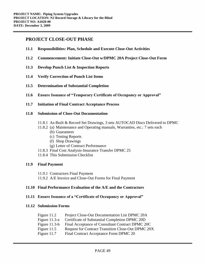
PROJECT NAME: Piping System Upgrades
PROJECT LOCATION: NJ Record Storage & Library for the Blind
PROJECT NO: A1028-00
DATE: December 3, 2009
PAGE 49
PROJECT CLOSE-OUT PHASE
11.1 Responsibilities: Plan, Schedule and Execute Close-Out Activities
11.2 Commencement: Initiate Close-Out w/DPMC 20A Project Close-Out Form
11.3 Develop Punch List & Inspection Reports
11.4 Verify Correction of Punch List Items
11.5 Determination of Substantial Completion
11.6 Ensure Issuance of “Temporary Certificate of Occupancy or Approval”
11.7 Initiation of Final Contract Acceptance Process
11.8 Submission of Close-Out Documentation
11.8.1 As-Built & Record Set Drawings, 3 sets AUTOCAD Discs Delivered to DPMC
11.8.2 (a) Maintenance and Operating manuals, Warranties, etc.: 7 sets each
(b) Guarantees
(c) Testing Reports
(f) Shop Drawings
(g) Letter of Contract Performance
11.8.3 Final Cost Analysis-Insurance Transfer DPMC 25
11.8.4 This Submission Checklist
11.9 Final Payment
11.9.1 Contractors Final Payment
11.9.2 A/E Invoice and Close-Out Forms for Final Payment
11.10 Final Performance Evaluation of the A/E and the Contractors
11.11 Ensure Issuance of a “Certificate of Occupancy or Approval”
11.12 Submission Forms
Figure 11.2 Project Close-Out Documentation List DPMC 20A
Figure 11.3-a Certificate of Substantial Completion DPMC 20D
Figure 11.3-b Final Acceptance of Consultant Contract DPMC 20C
Figure 11.5 Request for Contract Transition Close-Out DPMC 20X
Figure 11.7 Final Contract Acceptance Form DPMC 20

PROJECT NAME: Piping System Upgrades
PROJECT LOCATION: NJ Record Storage & Library for the Blind
PROJECT NO: A1028-00
DATE: December 3, 2009
PAGE 50
Figure 11.8.3-a Final Cost Analysis
Figure 11.8.3-b Insurance Transfer Form DPMC 25
Figure 11.8.4 Submission Checklist
XV. EXHIBITS
The attached exhibits in this section will include a sample project schedule, and any supporting
documentation to assist the Consultant in the design of the project such as maps, drawings,
photographs, floor plans, studies, reports, etc.
END OF SCOPE OF WORK

/
February 7, 1997Rev.: January 29, 2002
Responsible Group Code Table
The codes below are used in the schedule field “GRP” that identifies the group responsible for theactivity. The table consists of groups in the Division of Property Management & Construction(DPMC), as well as groups outside of the DPMC that have responsibility for specific actMties ona project that could delay the project if riot completed in the time specified. For reportingpurposes, the groups within the DPMC have been defined to the supervisory level ofmanagement (i.e., third level of management, the level below the Associate Director). to identifythe ‘functional group” responsible for the activity.
CODE DESCRIPTION REPORTS TO ASSOCIATE DIRECTOR OF:CM Contract Management Group Contract ManagementCA Client Agency N/A
CSP Consultant Selection and Technical ServicesPrequalification Group
A/E Architect/Engineer N/A
PR Plan Review Group Technical ServicesCP Construction Procurement Planning & AdministrationCON Construction Contractor N/A
FM Financial Management Group Planning & AdministrationOEU Office of Energy and N/AUtility Management
PD Project Development Group Planning & Administration
EXHIBIT ‘A’

SeIz
edon
duct
Pred
esig
m‘m
ject
Kh
V3O
2OP
rep
are
Pro
gra
mP
hase
Subm
itta
lA
VE
V3Z
iD
isui
bute
Prog
ram
Subm
ittal
forR
evie
wC
MO
O27
Prep
are
&S
ubtm
t Prh
ject
Cos
t Ana
lysi
s(D
PMC
-38)
CM
CV30
22R
evie
wSc
App
rove
Prog
ram
Subm
ittal
—p—
—.
——
tiW
iWij
in
iiH
.IU
,iH
iuo
1m
,Io
I:
V
CA
I: :1
IIII
I:
II
I;
IV
CV
3O
23R
evie
w&
Approv
ep
ro
gram
Su
bm
kta
lV
TV
TT
TH
fT
IW
V1V
T—
.—
.IV
IV
;i.
VV
I!iIV
IIV
1V
V:II
II
V
Cv30
24R
evie
w&
App
rove
Prog
ram
Subm
ittal
CM
II
CV
O25
Con
solid
ate
&R
etur
nP
rogr
amSu
bnut
tal
Com
men
tsC
Mi
CV30
30Pr
epar
eSc
hem
atic
Phas
eSu
bmitt
alA
VE
ICV
3031
Dis
trib
uteS
chem
atic
Subr
nitta
lfor
Rev
iew
CM
V
VIII
I:
——
____
L‘__
CV
3037
Prep
are
&S
ub
mit
Proj
ect C
ostA
naly
sis
(DPM
C38
)C
MI
I__
I.:I.V
i•V
Vl’I
IIV
I1
IIV
II
II_I
V
CV30
32R
evie
w&
App
rove
Sche
mat
icSu
bmitt
alCA
I
ICV
3C13
3R
evie
w&
App
rove
Sche
mat
icSu
bmitt
al:
I
ICV
3034
Rev
iew
&A
ppro
veSc
hem
atic
Subm
ittal
CM
-
—iV
ViV
:V
•I’’
i•
I1
IIIII!I.V
II.•V
V
C’3
li3s
Con
solid
ate&
Ret
urnS
chei
natic
Subm
lttal
Com
men
tC
MIII
III
iV
IjV
iiI
II
II
V3O
4GPs
epar
eDcs
ignD
evel
opm
entP
base
Subm
ittal
AVE
—
rLV
3O51
Dis
tribu
teD
DSu
bmitt
alfo
r Rev
iew
CMt4
7Pr
epar
eSc
Subm
itPr
ojec
t Cos
t Ana
lysi
s(D
PMC
-.38)
CM
IC
’l3O
4R
evie
wSc
App
rove
Des
ign
Dev
elop
men
t Sub
mitt
alC
AV
ItIII..,
VV
VV
VIII
Vii!
I•iI!
V
IIIV
iii!iiI
IV
CV30
43R
evie
wSc
App
rove
Des
ign
Dev
elop
men
t Sub
mitt
alPR
I
Rev
iew
ScA
ppro
veD
esig
nD
evel
opm
ent
Subm
ittal
CM
——
—-,
ii—
‘-°4
Con
solid
ate
&R
etur
nD
DSu
bmitt
alC
omm
ents
lI
Pre
pare
Fin
alD
esig
nP
hase
Subm
ittal
AE
ICV
3OSI
Dis
trib
ute
Fina
l Des
ign
Subm
ittal
forR
evie
wC
Mj
1C1
3O52
Rev
iew
ScA
ppro
veFi
nalD
esig
nSu
bmitt
alC
AI
Cv30
53R
evie
wSc
App
rove
Fina
lDes
ign
Subm
ittal
PRI
IC
V30
34R
evie
wFi
nal D
esig
nS
ubm
iti
for
Con
stcu
ctab
ihty
OC
SI
NO
TE
:D
EC
k-
TF
ST
Si,e
et1
of
3R
efer
to
sect
ion
“IV
Pro
ject
Sche
dule
”of
the
Bure
auof
Des
ign
&C
onst
ruct
ion
Ser
vic
esV
Scop
eof
Wor
kfo
rco
ntra
ctph
ase
dU
rati
Ons,
Routi
ne
Pro
ject
.EX
hib
it‘
‘@
Frim
aver
aS
yst
ems,
Inc.

FI
nhi1inhii1irnu1niiflhi!i14l4nHfi1:tiuh1n[ri1[Tn1 1.
...0
i!..
3a
I.PHi
::::

47
I
IIIII IEa
0
0—oa—
gQ
G
.
-
i.
Ca
z0
0
3:
0c—•—
.
jp
CaS.Ca
22222j2
*
1*HL=
I-:z::.zzzz::zz:zjjzz-.j..
—_.__L—
----
U.
.4
—1——.-
-----i
—--.---—-—.----—
-.__z.:..
-------C—_____-.
—4.—.
•--

r—
[z;:
New
Jers
eyR
ecor
dsS
troa
geC
ente
ran
dL
ibra
ryfo
rth
eB
lind
and
Han
dica
pped
EX
HIB
IT‘B
’
FORENSIC ANALYSIS AND REPORT
FOR
NEW JERSEY
DEPARTMENT OF THE TREASURY
DIVISION OFPROPERTY MANAGEMENT & CONSTRUCTION
At The
NEW JERSEY STATERECORDS STORAGE CENTER
AndLIBRARY FOR THE BLIND
2300 Stuyvesant AvenueTrenton, NJ
PREPARED BY
M&E Engineers, Inc.26 West High StreetSomerville, NJ 08876
Revision IMay 27, 2009

NJ-DPMC — State Records Storage CenterMay 27, 2009
TABLE OF CONTENTS
PURPOSE I
EXECUTIVE SUMMARY I
METHODOLOGY 2
EXISTING CONDITIONS 3
OBSERVATIONS & DISCUSSION 6PVC MATERIAL CHARACTERISTICSPIPE HANGERSTHERMAL EXPANSIONTHERMAL LIMITS
RECOMMENDATIONS 19GENERALOPTION IOPTION 2A & 2BOPTION 3
ENERGY CONSIDERATIONS 23
REFERENCES 23
BUILDING PIPING PLAN ATTACHED .PDF
M&E Engineers, Inc.

NJ-DPMC — State Records Storage CenterMay 27, 2009
PURPOSE
M&E Engineers, Inc. has been retained by the New Jersey DPMC to review theissue of piping failures throughout the water source heat pump distributionsystem at the New Jersey Record Storage Center and Library for the Blind,located at 2300 Stuyvesant Avenue, Trenton, NJ. The building was built in theearly 1980’s, and the heating and cooling is provided by water-source heatpumps, which are located throughout various areas of the building. The piping toand from each of the heat pumps is Poly Vinyl Chloride (PVC) plastic, which isoriginal to the building. Recently the piping has experienced a number offailures, which subjects the facility and the valuable objects therein, to potentialwater damage. Wholesale replacement of the piping system would beeconomically and logistically infeasible, because the building would have noheating or cooling for several months to accomplish this. The purpose of thisstudy therefore is to investigate the system and installation, so as to form anopinion of the root cause of these failures and to make recommendations, ifpossible, for the mitigation of the problem. In addition, M&E Engineers wastasked with tracing out the piping systems and identifying isolation valves withinthe system, such that a remediation plan could be subsequently developed.
EXECUTIVE SUMMARY
The study revealed a number of factors which have contributed to the rash ofpiping failures which have plagued the facility. In general, the plastic piping wasnot properly installed, and the selection of plastic for this application wassomewhat marginal in the first place. Theoretically, the PVC should have lasted50 to 70 years. However, the material is not robust enough to provide the safetyfactor that is required for this facility.
The survey was successful in tracing the existing piping, and identifying theexisting isolation valves. A copy of the building floor plan with piping and valvelocations is attached as an appendix.
This report presents data, photos, and documentation to support the findings, aswell as recommendations to remediate the problem. The options range fromlimited piping replacement to wholesale replacement of the HVAC System. Themerits and preliminary cost estimates are presented for each, and aresummarized below:
OPTION DESCRIPTION EST. COST1 Replace branch piping $ 466,2602A Install all new piping in ceiling $ 660,0002B Install all new piping on roof $ 624,0003 All new HVAC system $ 1,404,000
M&E Engineers, !nc. Page 1 of 23
NJ-DPMC — State Records Storage CenterMay 27, 2009
METHODOLOGY
M&E Engineers visited the site, and met with the New Jersey DPMC along withmembers of the building facility staff to gather information on the nature of the problemsexperienced. We subsequently conducted a tour and survey of the buildings mechanicalspaces to observe the installed water source heat pump piping system and associatedequipment. Our analysis is based upon review and observations of the current fieldconditions, equipment service record information provided to us by the New JerseyDPMC and the NJ. Record Storage Center Facilities Staff. Additional supportinginformation, i.e. engineering calculations and service recommendations were alsoreviewed.
The survey effort included tracing the mains to determine their as-built locations, and tolocate isolating valves that could be used to isolate portions of the system. Portions ofthe piping are exposed, some portions are concealed above lay-in ceilings, and someportions are located above gypsum board ceilings, and are only accessible thoughceiling access doors.
One of the initial recommendations made by M&E Engineers was to have sections ofpiping that had failed analyzed by a testing laboratory. However, two problems stood inthe way of this concept. One was that the facility did not keep any of the failed pipingsections, so none were available. We do realize that sections of existing pipe could beremoved, but there would be no way of knowing whether these pipe sections had beensubject to the same stresses that failed sections had been. The second problem wasthat discussion held with several testing laboratories revealed that they did not have atest protocol, or any basis upon which to evaluate an analysis. We eventually did locatea company that specializes in plastics, but the DPMC advised that it did not wish toproceed with laboratory analysis.
Another aspect of this study was to research available technical literature in regard tothe expected useful of PVC Piping, and factors that could lead to premature failure. Thisis discussed under the materials section of the report.
We have developed estimates of probable cost for each of the options presented. Wemust note however that the cost estimates are based upon take-offs of the existingpiping, and are only approximations. Furthermore, the costs estimates are verydependent upon the “Difficulty Factor” associated with working within the existingbuilding, with regard to scheduling, temporary protection, physical access to the piping,and other logistical issues. We have attempted to reflect reasonable multipliers in theestimates to account for these difficulties, but these are rather subjective, and will alsodepend on the level of restrictions that will ultimately be imposed upon the contractor.We therefore caution that while the estimates can be used for the sake of comparingoptions, the final budget allocation for the project may need to be adjusted accordingly.
M&E Engineers, Inc. Page 2 of 23

EXISTING CONDITIONS
NJ-DPMC — State Records Storage CenterMay 27, 2009
1. The New Jersey Record Storage Center and Library for the Blind is located at2300 Stuyvesant Avenue, Trenton, New Jersey. The building consists of a singlestory structure of approximately 94,000 square feet, including a central core,offices and work rooms, storage areas, library and mechanical spaces.
2. As the name of the building suggests, there are vast amounts of documentsarchived in this facility. The value of the documents would be hard to estimate,but it is obviously critically important that they be protected from water damage.
3. The building was constructed in the early 1980’s, and the existing systems arenow approximately 28 years old. The majority of the mechanical equipmentappears to be in fair operational condition, though some of the heat pumps havebeen replaced. The heat pump piping within the mechanical room and out to thefluid cooler is black steel pipe. The heat pump water loop piping beyond themechanical room appears to be a mixture of schedule 40 and schedule 80 Pvc.Recently many of the schedule 40 portions of the piping loop have experienced
Example of Historic Archived Documents
M&E Engineers, Inc. Page 3 of 23

NJ-DPMC — State Records Storage CenterMay 27, 2009
failures and in many visible areas the schedule 40 piping is in poor condition. Therecent piping failures have resulted in leaks and damage throughout the building.
4. The existing heating and cooling system is a water source heat pumparrangement consisting of a central mechanical space which houses the heatpump water supply loop pumps, electric boiler and storage tank. The habitablespaces throughout the building are served by horizontal heat pumps mountedthroughout the hung ceiling spaces. Two roof mount heat recovery units withreheat provide ventilation for the office and other non-storage areas, by blowingoutside air into the ceiling plenums. The archive storage areas at the rear of thebuilding are served by roof mounted water source heat pumps. A three cell fluidcooler on grade provides the heat rejection as required to keep the water loopbelow the designated temperature. Conversely, the electric boiler will add heatto the loop as required in the winter to maintain a minimum loop temperature.Since the original 1980 installation various pieces of equipment have been eitherrepaired or replaced and with exception of portions of the piping loop appear tobe in acceptable operating condition.
a. Cooling —Entering condenser water temperature (Deg. F) - 90.0
b. Heating —Entering condenser water temperature (Deg. F) - 70.0
c. Total system GPM - 903
5. This system is a “Closed-Loop”, meaning that it does not lose water as part of it’snormal process. Furthermore, the fluid is never exposed to the ambient air, sothere is no oxygenation of the fluid. The fluid cooler is a closed-loop apparatus,as opposed to a cooling tower.
6. Since the system is a closed-loop, there is minimal need for water treatment.Since the system does not use direct evaporization, or require blow-down, it doesnot require significant make-up water. The existing chemical treatment is fullycompatible with PVC. It is unknown whether any different chemical treatmentsystems were used in the past. It is possible that a different type of system wasused in the past, bit it is unlikely that it would not have been compatible.
7. The original heat pumps were manufactured by Command-Aire, which was laterpurchased and absorbed by the Trane Company. All of the replacements havebeen made with Trane Units, which is the same product line as the original. Theheat pumps range in size from % Ton to 5 Tons.
M&E Engineers, Inc. Page 4 of 23

NJ-DPMC — State Records Storage CenterMay 27, 2009
8. The approximate extent of the existing piping is listed below:
Schedule 40 Pvc Piping
Pipe Size Length of Pipe(in) (ft)8 06 205 2444 363 252
2-1/2 1082 644
1-1/2 1061-1/4 236
1 2803/4 540
Total 2,466
Schedule 80 vc Piping
Pipe Size Length of Pipe(in) (ft)
8 1546 505 04 763 0
2-1/2 02 0
1-1/2 01-1/4 0
1 03/4 0
Total 280
M&E Engineers, Inc. Page 5 of 23

NJ-DPMC — State Records Storage CenterMay 27, 2009
OBSERVATIONS AND DISCUSSION
General
Several conditions were observed at the site that should certainly be consideredas factors in the piping failures. They are as follows:
1. Inadequate and improper piping supports — In numerous areas, weobserved pipe hangers which were not adjusted to the correct length, suchthat the hanger was not supporting the pipe at all. This adds stress due toexcessive deflection, and concentrates a greater load on the adjoininghangers. In many other areas, and particularly right near the unitconnections, the lack of adequate hangers was so extreme that the pipe isvisibly bent and contorted. This obviously places stress on the pipingabove and beyond the intent.
2. Lateral piping movement — The 8” mains which leave the mechanical roomwere visibly swaying I to 2 inches. While not a direct factor, this and otherobservations indicate that the piping was not properly anchored, guided,and thermally compensated.
3. Thermal runaway conditions — The operating engineers noted that thereare no safeties to shut down the heat pumps on a loss of flow. Therefore,when the main circulating pump has failed, the heat pumps continue torun. This can cause a tremendous thermal stress, which is discussedfurther later in this report.
In order to analyze the installation and to search for the root cause of the pipingfailures, we have broken down the information and discussion into the followingtopics:
• PVC Material Characteristics• Thermal Expansion• Pipe Hanger Requirements• Thermal Limits
The seemingly relevant aspects of each of these topics are delineated in thefollowing sections.
M&E Engineers, Inc. Page 6 of 23

NJ-DPMC — State Records Storage CenterMay 27, 2009
PVC Material Characteristics
The first question that must be resolved is the overall suitability of the pipingmaterial for the application. The piping has various markings and is present inboth white and grey. Plastic pipe is manufactured to ASTM Standards, however,there are variations in the exact formulations of the plastics from manufacturer tomanufacturer.
Polyvinyichioride (PVC) has a linear structure similar to polyethylene but with achlorine atom replacing a hydrogen atom on alternate carbon atoms. PVC itselfis hard and rigid. Phthalate esters can be added as plasticizers to make it softfor certain applications where rigidity is not desired. There are at least 20different formulations that are called PVC.
The durability of PVC pipes is related, as it is for all other thermoplasticsmaterials, to the chemical degradation of the polymer, used in the pipes.However unlike other thermoplastic pipes PVC pipes do not oxidize.
Stabilizers are used in PVC pipes to prevent degradation of the polymer duringthe extrusion process. Barring exposure to certain chemical compounds, nochemical degradation is expected to take place. For this reason the durability ofthe PVC material is expected to be very long, and may even be more than 1000years’.
In standardized pipes for water the expected lifetime of PVC pipes underpressure is extrapolated based on hoop stress testing of pipes for up to 20000hours. This then allows an estimation of the durability by extrapolation to a lifeexpectancy under pressure of 50 to 100 years”.
The physical properties of PVC Pipe are provided on the following pages forreference.
M&E Engineers, Inc. Page 7 of 23
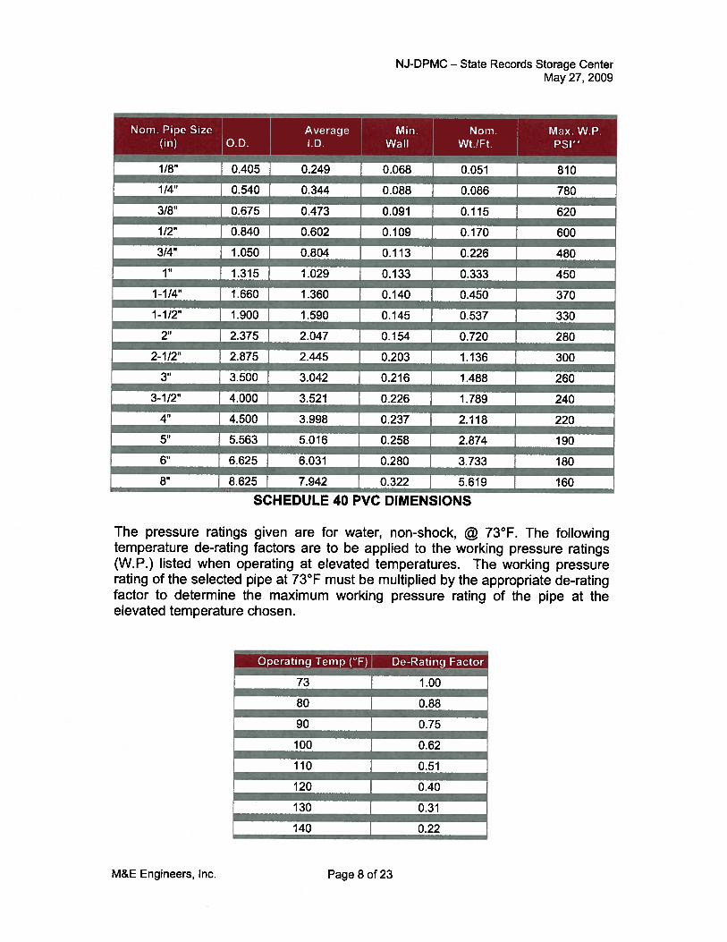
NJ-DPMC — State Records Storage CenterMay 27, 2009
Nom. Pipe Size j Average Mm. Nom. Max. W.P.(in) O.D. 1.0. WaIl Wt./Ft. PSI
—-—
1/4” 0.540 0.344 0.088 0.086 780
3/8’ 0.675 0.473 0.091 0.115 620
1/2’ 0.840 0.602 0.109 0.170 600I — —
314” 1.050 0.804 0.113 0.226 480I — — —
1” .315 1.029 0.133 0.333 450I — — —
1-1/4” 1.660 1.360 0.140 0.450 370I — — —
1-1/2” 1.900 1.590 0.145 0.537 330I —
2” 2.375 2.047 0.154 0.720 280
2-1/2” 2.875 2.445 — 0.203 1.136 300—-- I --
3” 3.500 3.042 0.216 1.488 260-
3-1/2” 4.000 3.521 0.226 1.789 240
4” 4.500 3.998 0.237 2.118 220
5” 5.563 5.016 0.258 2.874 190
6” 6.625 6.031 0.280 3.733 180
8” 8.625 7.942 0.322 — 5.619 160
SCHEDULE 40 pvc DIMENSIONS
The pressure ratings given are for water, non-shock, @ 73°F. The followingtemperature de-rating factors are to be applied to the working pressure ratings(W.P.) listed when operating at elevated temperatures. The working pressurerating of the selected pipe at 73°F must be multiplied by the appropriate de-ratingfactor to determine the maximum working pressure rating of the pipe at theelevated temperature chosen.
Operating Temp (°F) De-RatingFor
-
80 0.88-
90 0.75
100 0.62
110 0.51
120 OAO
130 0.31
140 0.22
1/8” 0.405 0.249 0.068 0.051 810
73 1.00
M&E Engineers, Inc. Page 8 of 23

NJ-DPMC — State Records Storage CenterMay 27, 2009
Heat Deflection Temperature Under Load170 ASTM D648(264 psi, annealed)
Specific Heat, CaI./°C/gm 0.25 ASTM D2766
PVC PHYSICAL PROPERTIES
Coe dent of 1 i Conductivity(Cal.)(cm)I(cm2)(Sec.)(°C) 3.5 x 10BTU/in/hr/ft.2/°F 1.02WaWm/°K 0.147
ASTM C177
M&E Engineers, Inc. Page 9 of 23
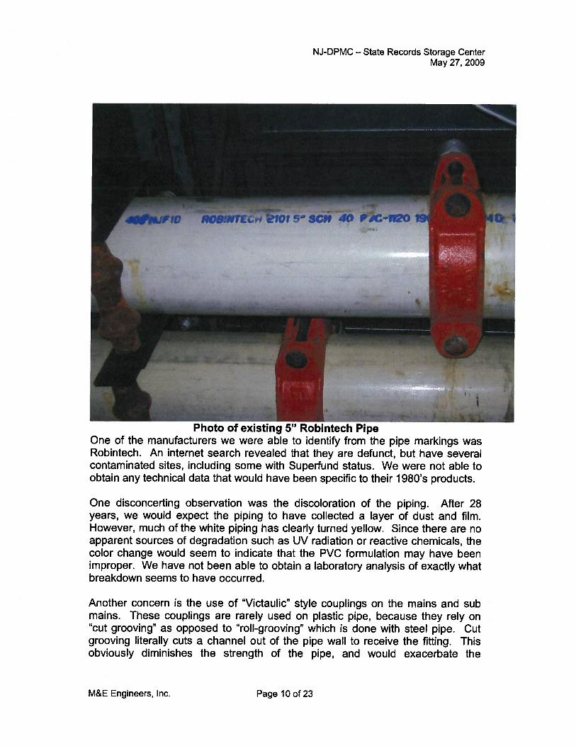
NJ-DPMC — State Records Storage CenterMay 27, 2009
One disconcerting observation was the discoloration of the piping. After 28years, we would expect the piping to have collected a layer of dust and film.However, much of the white piping has clearly turned yellow. Since there are noapparent sources of degradation such as UV radiation or reactive chemicals, thecolor change would seem to indicate that the PVC formulation may have beenimproper. We have not been able to obtain a laboratory analysis of exactly whatbreakdown seems to have occurred.
Another concern is the use of “Victaulic” style couplings on the mains and submains. These couplings are rarely used on plastic pipe, because they rely on“cut grooving” as opposed to “roll-grooving” which is done with steel pipe. Cutgrooving literally cuts a channel out of the pipe wall to receive the fitting. Thisobviously diminishes the strength of the pipe, and would exacerbate the
Photo of existing 5” Robintech PipeOne of the manufacturers we were able to identify from the pipe markings wasRobintech. An internet search revealed that they are defunct, but have severalcontaminated sites, including some with Superfund status. We were not able toobtain any technical data that would have been specific to their 1980’s products.
M&E Engineers, Inc. Page 10 of 23

NJ-DPMC — State Records Storage CenterMay 27, 2009
problems associated with anchoring the pipe for thermal expansioncompensation.
A review of available technical literature for the longevity of PVC was allfavorable in terms of the expected lifespan. Most of the studies performedhowever are based upon it’s use for underground water mains. There is a wealthof studies from the U.K. and elsewhere that conclude PVC is expected to last atleast 60 years. Again, almost all of these studies are based upon anunderground installation. There were no studies found that reviewed failuressuch as those experienced at this facility.
Original Piping and Replaced Sections(Note color difference)
M&E Engineers, Inc. Page 11 of 23

PIPE HANGERS
NJ-DPMC — State Records Storage CenterMay 27, 2009
The ANSI Code for pipe hangers does not specify the hanger spacingrequirements for plastic pipe. It instead refers the installer to the productmanufacturer. Since Robintech is no longer in business, we have reproducedthe hanger chart from a current manufacturer below:
¶_3/8 4 4 31/2 21/2 2
—
1/2 41/2 41/2 4 21/2 21/2I —
3/4 4 4 1/2 4 2 1/2 2 1/2
1 51/2 5 41/2 3 21/2—
11/4 51/2 51/2 5 3 3
11/2 6 51/2 5 31/2 3
2 6 51/2 5 31/2 3-
21/2 7 61/2 6 4 31/2
3 7 7 6 4 31/2
31/2 71/2 7 61/2 4 4
4 71/2 7 61/2 41/2 4
6 81/2 8 71/2 5 41/2- —
6x118 71/2 7 61/2 41/2 4— —I8 9 81/2 8 5 41/2
— —10 10 9 81/2 51/2 5— —__12 11 1/2 10 1/2 91/2 61/2 51/2
HARVEL PVC PIPE HANGER SPACING
Support location and spacing is dependent on the pipe diameter, operatingtemperature of the system, and the location of any concentrated stress loads(i.e., valves, flanges, and any other heavy system components). Proper supportspacing is critical to ensure that deflection is kept to a minimum. Hangers usedmust have an adequate load-bearing surface free of any rough or sharp edgesthat could damage the piping during use. They must also not restrict linearmovement of the system due to the effects of expansion and contraction;overtightening must be avoided
In addition, hangers should be located within one foot of each change ofdirection. There are a total of 61 Heat Pumps connected to the system. The
1/4 3 1/2 3 1/2 2
M&E Engineers, Inc. Page 12 of 23

NJ-DPMC — State Records Storage CenterMay 27, 2009
majority of the units are made with nominal 1” connections. However, there arealso some units with %“ connections, as well as some with 1-1/4” connections.
As can be seen from he photos below, the hanger spacing greatly exceeds thismanufacturers recommendations by a great deal. Some are completelydisconnected.
F .ing Not Supported at LJrection (flanges
M&E Engineers, Inc. Page 13 of 23

NJ-DPMC — State Records Storage CenterMay 27, 2009
— isconnected 1-oregro U nt, Jpacing
M&E Engineers, Inc. Page 14 of 23

NJ-DPMC — State Records Storage CenterMay27, 2009
Each heat pump is connected to the piping system with a set of braided stainlesssteel flexible hoses. After the hoses, there is additional piping and valves thatare referred to as the “Trim” package on the unit. In many instances, the weightof the hoses and trim kit is all hanging from the unit and PVC branch lines,imposing quite a bit of deflection and stress onto the PVC piping.
Bending Stresses from Inadequate Hangers
M&E Engineers, Inc. Page 15 of 23

NJ-DPMC — State Records Storage CenterMay 27, 2009
Thermal Expansion
This system is considered an “Ambient” temperature system. That means thatbecause the loop temperature is normally between 70°F and 90°F, the thermalexpansion coefficient is quite small, and is approximately 1-1/4” per 100 feet ofpipe. However, the allowable stresses in plastic pipe are also much lower thanthose of copper tubing or steel pipe, so plastic piping requires just as muchattention to anchoring, guiding, and expansion compensation as more traditionalpiping materials. A rule of thumb for temperature variations of this range is toinstall the system with offsets, bends or expansion joints as for a 100 psi steamline.
BRANCH PIPING ANCR
M&E Engineers, Inc. Page 16 of 23

NJ-DPMC — State Records Storage CenterMay 27, 2009
The 8” mains that exit the mechanical room were visibly moving by 1” to 2” in theaxial direction. This is a clear indication that there is no anchoring, and therepetitive motion is not good for the piping, joints, and serves to further loosenthe hangers.
As another case in point, in the photo on the proceeding page, the branch pipingis anchored by the masonry construction. This can lead to unacceptable pipestresses if the mains move due to thermal expansion. From our observations, itappears that all of the piping was installed without a plan for anchoring, thermalexpansion, and pipe movement. Rather, it appears that de facto anchors werecreated at fire rated walls, but without consideration of how that might impact thepipe system stresses.
We can also observe in the photo above the fact that the pipe is not sitting in themiddle of the roller hanger, where it belongs, but rather is sitting cock-eyed ontop of the roller flange. So instead of spreading out the weight load and allowingaxial movement, this hanger places a high stress point onto the pipe, and axialforces will generate friction and wear at the support point.
M&E Engineers, Inc. Page 17 of 23

NJ-DPMC — State Records Storage CenterMay 27, 2009
Thermal Limits
The other factor that may be a significant contributor to the piping failures is thefact that the system and piping temperature sometimes deviates far beyond thedesign condition. This subjects the plastic piping to more severe forces, at thesame time that the strength of the PVC is compromised.
The heat pump loop temperature is designed for a nominal range between 70°Fand 90°F. However, there is anecdotal evidence from the operating engineersthat there are times when the temperature far exceeds the upper limit. If or whenthe main circulating pump fails, the heat pumps lose flow. However, theycontinue to run, because they apparently are not equipped with flow-switchsafety sensors. Units that are in the cooling mode when the pump fails willcontinue to run, and continue to reject heat to the now-stagnant fluid in theircondensers. The units can be expected to run until their high-head refrigerantpressure switches activate. We have confirmed with the Trane Company that thehigh-pressure setting on these units corresponds to a temperature ofapproximately 130 °F. The piping in the immediate vicinity of the heat pumpwould therefore be exposed to that temperature, and would be expected to getclose to that temperature.
This condition would have two detrimental affects simultaneously. The first isthat this piping would have rapid and unequal thermal expansion at least doublewhat it should otherwise be exposed to. The second affect is that at an elevatedtemperature of this level, the plastic itself loses a great deal of its physicalstrength. The 1-1/4” piping, for example, is nominally rated at 370 psi. Thetemperature derating factor of 0.31 at 130°F would reduce this value to just 114psi. While the system normally operates at approximately 30 psi, additionalstresses from the inadequate support, and from water hammer, can easilyexceed this rating for short periods.
M&E Engineers, Inc. Page 18 of 23

NJ-DPMC — State Records Storage CenterMay 27, 2009
RECOMMENDATIONS
The threat of water damage to the property and archival materials stored in therecords center require that some mitigation be pursued to reduce the risk offuture pipe failures. The cost-benefit of each option depends upon the level ofrisk reduction achieved, multiplied by the financial impact of damaging archivedmaterials. Both of these measures are nebulous, and the evaluation musttherefore be made on a subjective basis.
The recommendations are offered as several options, and are presented in orderfrom the lowest cost (and lowest risk reduction) to highest cost (andcorresponding greatest risk reduction).
The notion of replacing any of the piping “in-kind” with new PVC is dismissed. Inour opinion, the continued use of PVC does not serve to effectively mitigate therisks, when compared to other alternatives. The vulnerability of the PVC totemperature and stress problems makes it the least desirable material. Thematerial cost is quite small compared to the labor cost, and the option to replacethe piping with CPVC or copper makes much more sense. The cost of installingcopper would be slightly higher than for CPVC, but this reduces the use of VOCsolvents in the building. The copper connections could be made with “Pressfit”fittings, up to the point where the transition back to plastic would be made.
Option 1. Replace Heat Pump Branches Only
All of the failures thus far that were reported have occurred in the smaller branchpiping. The mains and sub-mains have not suffered any failures thus far.Therefore, the most obvious and easily justified cost is to just replace theseindividual heat pump branches. Of course, this is still a very large undertaking,because the system must remain in service while the work is performed.
The scope of work under this option would include replacing all of the %“, 1”, and1-1/4” tubing. This would occur on a unit by unit basis, replacing and resupporting the branches from each unit back to the main or sub-main. This is theleast disruptive and least expensive option, but leaves the facility with thecontinued risk of exposure to failures from the sub-mains and mains.
Approximately one half of the heat pumps are connected directly to the mains,and do not have isolation valves. This will require a risky and prolongedshutdown of the entire system, in order to drain the system and cut in valves onthose branches which do not have them.
The preliminary estimate of probable cost for this option is Four Hundred SixtySix Thousand, Two Hundred Sixty Dollars ($466,260), not including engineeringcosts, permits and other DPMC loading. The cost estimate is based upon the
M&E Engineers, Inc. Page 19 of 23

NJ-DPMC — State Records Storage CenterMay 27, 2009
use of copper tubing, since our estimate for using CPVC only represented asavings of about Two Percent.
Under this scenario, we recommend that the Heat Pumps controls be modifiedsuch that they will shut down on loss of flow. New units which are purchasedgoing forward can be ordered with this feature from the factory. The existingunits however would need to be modified. This could be accomplished with aflow switch at each unit, installed at the same time the unit is re-piped. Onepossible alternative is to use one system flow switch, and connect to the heatpumps by utilizing the existing fire alarm shutdown circuit. This would need to bethoroughly investigated to be certain it did not compromise the life-safety aspectof that wiring.
We also recommend retrofitting the existing mains and sub mains withengineered anchors, guides, expansion compensation, and additional hangers.The existing piping needs to be properly supported and the thermal expansioncontrolled such that it does not overstress the piping. This work has beenincluded in the estimate of probable cost.
Option 2A & 2B — Provide New Piping System
Option I comes with some inherent risk and logistical difficulties. Working on anactive hydronic system carries risk of leaks and coupling or fitting failures. Sincethe system is active, each section needs to be drained. The poor condition of thecurrent installation means that sections of piping will be trapped, and some pipingthat is thought to be drained will still contain some water, which will come outsections are cut for removal. Certainly precautions can be taken, but ultimatelyMurphy’s Law is likely to prevail, with potential damage to the building orarchived materials.
Proper pressure testing of newly installed piping sections would require thatthose sections remain under test for a period of time to be certain they hold, andPVC cannot be tested with air. Given the value of the stored materials, a 1 hourhold test might not be considered acceptable. This would mean that the unitsserved by these piping sections would not be operable for extended periods.This poses a significant inconvenience to the operation of the facility for theentire duration of the project.
Options 2A & 2B provide alternatives that would significantly reduce the risk andminimize the inconvenience by providing an entirely new piping system. Option2A is to provide a new system inside the building. Option 2B is to provide a newpiping system on the roof, and to penetrate with branch piping to the heat pumpsbelow.
M&E Engineers, Inc. Page 20 of 23
NJ-DPMC — State Records Storage CenterMay 27, 2009
Under Option 2A, new steel mains and copper branches could be installedparallel (with adjustments for thermal expansion) to the existing. This pipingsystem could be properly pressure tested and accepted, and then the heatpumps can be “swung-over” from the plastic system to the new system. The oldsystem could then be drained and either removed or abandoned. (Removalwhere exposed and abandoned where concealed might be an option.)
Under Option 2B, new steel mains and copper branches could be installed on theroof. As per option 2A, this piping system could be properly pressure tested andaccepted, and then the heat pumps could be “swung-over” from the plasticsystem to the new system. The old system would then be drained and eitherremoved or abandoned. This option is less expensive, but does introduce twoother concerns. The number of pipe portals that would be required to connectthe piping from the mains to the heat pumps each represent a potential source ofroof leaks. It might be prudent under this scenario to provide a new roof inconjunction with the mechanical work. Additionally, the piping would be exposedto ambient temperatures, which would require the use of an anti-freeze solution.Furthermore, the piping would need to be insulated, and would still have someenergy losses from being outside.
This additional material costs for these options would be somewhat offset by thereduced labor that is involved in re-working the existing piping, draining, testing,and filling operations, and would provide the facility with a completely newsystem.
The preliminary estimate of probable cost for Option 2A is Six Hundred SixtyThousand Dollars ($660,000): and the estimate for Option 2B is Six HundredTwenty Four Thousand Dollars ($624,000), not including engineering costs,permits and other DPMC loading.
Option 3— Provide New Rooftop HVAC Systems
In our view, a Records Storage Center should not have HVAC Units and waterpiping running throughout the building. The sprinkler system represents a similarthreat, but statistics from the insurance industry indicate that the losses fromaccidental discharges from sprinkler systems are minimal, and the protectionagainst large-scale loss greatly outweighs that risk. The threat of leaks from anHVAC piping system however is significantly higher, and there is no reason thatthis system needs to be within the space.
Given the nature of the building, the HVAC Equipment and associated energydistribution should be outside of the archive areas. The three Storage Bays areequipped with rooftop units, but their piping still runs through the archive area.The building has a flat, empty roof, and new rooftop units could rather easily beinstalled.
M&E Engineers, Inc. Page 21 of 23

NJ-DPMC — State Records Storage CenterMay 27, 2009
There are many logistical and schematic-level questions that this approach wouldinvoke. Would/could we replace with an equivalent number of units (61) andconnect into the existing distribution ductwork? Or would we provide a smallernumber of larger air handlers, and do a combination of re-using and newductwork? The notion of running exposed ductwork above a roof is not a greatidea, as the duct penetrations and energy loss from outside ductwork are worsethan they are for piping, as discussed under option 2B. But this scenario doesprovide the greatest risk reduction to the archived materials.
Consideration of a totally new HVAC system should also be considered in light ofthe fact that the existing system, save those heat pumps that have beenreplaced, is all past the end of its expected life. The remainder of the heatpumps, as well as the circulating pumps, boiler, and fluid coolers are all due forreplacement. If the cost of replacing all of that equipment is taken intoconsideration, then the concept of a whole new system becomes a far lowermarginal cost.
There are many different ways that a new system could be deployed in thisbuilding, and each has significant benefits, as well as significant difficulties toface for implementation. We therefore offer this more as a general concept thata recommendation for a specific new HVAC system. We have developed thecost estimate based upon central station, water cooled heat pumps on the roof.But developing all of the implications and cost factors to evaluate various systemtypes is beyond the scope of this study, and would require a detailed energyanalysis in addition to the logistics assessment. We offer this one possiblesolution of this type to facilitate the decision making process.
The preliminary estimate of probable cost for this option is One Million FourHundred Four Thousand Dollars ($1,404,000), not including engineering costs,permits and other DPMC loading.
M&E Engineers, inc. Page 22 of 23

NJ-DPMC — State Records Storage CenterMay 27, 2009
Energy Considerations
The existing water-source heat pump system is probably quite efficient, due tothe configuration of the building. While an energy analysis is not within the scopeof this study, our experience with similar buildings with this type of system wouldsuggest that the Energy Utilization Index for the building is probably quite good,and we would expect the Energy Star Rating for this building would be relativelyhigh. This is due to the fact that the interior zones of the building are rejectingheat to the water loop for many hours of the year, while the perimeter zones areabsorbing heat from the loop. This means that the interior waste energy isrecovered and used for perimeter heating, and the loop is in balance for asubstantial portion of the year. The use of the boiler and fluid cooler to moderatethe loop temperature is thereby minimized.
This system does have the potential to be used in conjunction with either aclosed-loop or open-loop geothermal system. However, this would require adetailed analysis and energy modeling to determine the effectiveness of such aproposal, which is beyond the scope of this study.
REFERENCES:
Janson, Lars Eric 1996 “Plastics Pipes - How long can they last? KP CouncilNov. 1996
EN-ISO 9080
M&E Engineers, Inc. Page 23 of 23

.e1
z
z
z
C
z
C
I
0In
>-
z 0——
< wuJ JwOc,,jLr >cl.QODCI)WC,)’D
OcrWwJ OO0wD0Ow—<w<=d W
C,)
. crLLJZ
9aZ Wi-(DO O<ZO
°.zcra)-crc,)<°-
WDZ<QOQHQOwcr<Qrn
0z
->
cf)a3wo>-J
cEiO
00u-z0>..<w
a
cDO
wZ
CI)01-cr0Ow00uJ<
ZQ)
Cl)w
<01<C/)W
IUIUTfflLEJ
EXHIBIT ‘D’
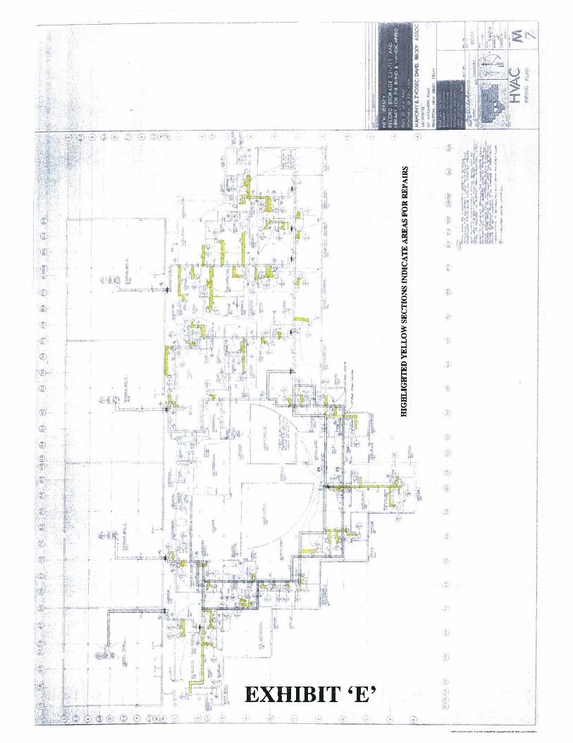
4 ‘
* ;:‘
%• : r: -p
:1*
c(vLG .h*N’! E; (• V V:’) ®H1\
r j_t’
4
I- -—EL’.— ,— n—i I —[k I Hr -$
?fr
I
- La J 4L it-(Z) •
t:i 1cjtI —
- I
c) ‘ 1N2
I L -
I I I_.__÷ N 2
W Ij7JIbi4LI — 1 —. _.ttr II
I rzH__zzz
...._ 2 F
I• I r”
II
;-$ I Rç,I
I I
2 - N • h . •‘1.i —-H P }.-li I
EXHIBIT ‘E’
-———-—I—
——- 0
C T HI
:
(I
in
-I
• 32efl. P
if)
‘iii•
i2
jgç_________
()
()
C,
V