Embed Size (px)
Citation preview

STATE OF NORTH CAROLINA
DEPARTMENT OF TRANSPORTATIONMICHAEL F. EASLEY LYNDO TIPPETT
GOVERNOR SECRETARY
MAILING ADDRESS:NC DEPARTMENT OF TRANSPORTATIONALTERNATIVE DELIVERY UNIT1591 MAIL SERVICE CENTERRALEIGH NC 27699-1591
TELEPHONE: 919-250-4128FAX: 919-250-4119
WEBSITE: WWW.NCDOT.ORG
LOCATIONCENTURY CENTER COMPLEX
ENTRANCE B-21020 BIRCH RIDGE DRIVE
RALEIGH NC
January 23, 2008
MEMORANDUM TO: 2001 Roadway Design Manual Holders
FROM: Rodger D. Rochelle, PEState Alternative Delivery Engineer
SUBJECT: 2001 Roadway Design Manual June Revision and New Guidelines for Revisions
Please find attached revisions and new guidelines to Part I and Part II of the 2001 RoadwayDesign Manual. Please insert these revisions in your Manual in the appropriate place. Theserevisions are effective immediately. This transmittal letter should be detached from the revisionand inserted in front of the Manual for future reference. Please recycle discarded pages fromyour manual. The 2001 Roadway Design Manual has been updated and is available on the webat:
http://www.ncdot.org/doh/preconstruct/altern/value/manuals/
If you have any questions and comments about this revision or the Roadway Design Manual,please contact Mr. Frankie Draper or Mr. Robert McKeithan of my staff at (919) 250-4234.
REVISION NOVEMBER 2007
Part I – Roadway Design Manual
1. INTRODUCTION
Note: Design Services Deleted from all references.
Remove and discard 1 sheet and replace with 1 revised sheet

2001 Roadway Design Manual November Revision November 23, 2008Page 2 of 12
2. PART 1 UTILIZATION OF DESIGN MANUAL AND MANUAL FORMAT
Note: Design Services Deleted from all references.
Remove and discard 1 sheet and replace with 1 revised sheet
3. Chapter 1-Section 1 DESIGN POLICY INTERPRETATION
Note: A Policy on Geometric Design reference updated from 2001 to 2004.
Remove and discard 1 sheet and replace with 1 revised sheet
4. Chapter 1-Section 1-1, 1-1A, and 1-1B.
Section 1-1 SELECTION OF PROJECT DESIGN CRITERIA
Note: Design Services Deleted from all references.
Section 1-1B DESIGN SPEEDS
Note: A policy on Geometric Design reference updated from 2001 to 2004.
Section 1-C TRAFFIC VOLUMES
Note: Design Services Unit reference changed to Alternative Delivery.
Note: A policy on Geometric Design reference updated from 2001 to 2004.
Section 1-D TERRAIN CLASSIFICATIONS
Note: A policy on Geometric Design reference updated from 2001 to 2004.
Section 1-E PROJECT COST REDUCTION GUIDELINES
Note: A policy on Geometric Design reference updated from 2001 to 2004.
Remove and discard 6 sheets and replace with 6 revised sheets
5. Chapter 1-Section 1-4B USABLE AND GRADED SHOULDERS
Note: Assistant Head of Roadway Design or the Engineering Coordinator of Design Services has been changed to Assistant State Roadway Design Engineer.
Remove and discard 1 sheet and replace with 1 revised sheet
2001 Roadway Design Manual November Revision November 23, 2008Page 3 of 12
6. Chapter 1 Section 1-4C N.C. DOT PAVED SHOULDER POLICY
Note: Design Services Engineer deleted from reference.
Remove and discard 1 sheet and replace with 1 revised sheet
7. Chapter 1 Section 1-4G PAVED SHOULDERS WITH RIGID PAVEMENT
Note: Econocrete reference changed to concrete shoulder.
Remove and discard 1 sheet and replace with 1 revised sheet
8. Chapter 1 Section 1-6F MEDIAN SLOPES
Note: Change reference of Figure 2A thu 4 to Figure 1 thru 4.
Remove and discard 1 sheet and replace with 1 revised sheet
9. Chapter 1 Section 1-8 RAISED ISLANDS
Note: For widths greater than 16’, cost-comparison should be made betweenmonolithic islands and grass covered islands instead of 3” concrete.
Note: Delete covered islands in the sentence regarding construction cost.
Note: Contract Office Project Engineer in Design Services is now changed to PlansStandards Engineer in Project Services.
Section 1-11 SPIRAL CURVES
Note: A policy on Geometric Design reference updated from 2001 to 2004.
Remove and discard 1 sheet and replace with 1 revised sheet
10. Chapter 1 Section 1-12, 1-13, 1-14, 1-15 and 1-16
Note: A policy on Geometric Design reference updated from 2001 to 2004.
Note: Roadway Design Assistant Unit Head changes to Assistant State Roadway DesignEngineer.
Remove and discard 3 sheets and replace with 3 revised sheets
12. Chapter 1 Section 1-17, 1-18, and 1-19

2001 Roadway Design Manual November Revision November 23, 2008Page 4 of 12
Note: A policy on Geometric Design reference updated from 2001 to 2004.
Remove and discard 1 sheet and replace with 1 revised sheet
13. Chapter 2 Section 2-1 MISCELLANEOUS DESIGN CRITERIA
Note: Reference Design Services Unit changed to Alternative Delivery Unit.
Note: Removed reference State Design Services Engineer.
Section 2-2 CLIMBING LANES
Note: Reference Design Services Unit changed to Alternative Delivery Unit.
Note: A policy on Geometric Design reference updated from 2001 to 2004.
Note: Removed reference to Engineering Coordination Engineer.
Section 2-5 TRUCK ESCAPE RAMPS
Note: A policy on Geometric Design reference updated from 2001 to 2004.
Note: Design Services Unit reference changed to Alternative Delivery Unit.
Section 2-6 BARRIERS FOR NOISE ABATEMENT
Note: A policy on Geometric Design reference updated from 2001 to 2004.
Note: Design Services Unit reference changed to Alternative Delivery Unit.
Note: Removed reference to Design Services Unit.
Section 2-7 CUL-DE-SACS
Note: Deleted “and Design Services Unit”
Note: A policy on Geometric Design reference updated from 2001 to 2004
Remove and discard 5 sheets and replace with 5 revised sheets
16. Chapter 3 Section 3-2E STRUCTURE ANCHOR UNITS
Note: General Updates.
Remove and discard 2 sheets and replace with 2 revised sheets.

2001 Roadway Design Manual November Revision November 23, 2008Page 5 of 12
17. Chapter 3 Section 3-10 GUARDRAIL ATTACHMENT AND RETROFIT MANUAL.
Note: Removed Design Services Unit from Reference.
Note: Changed Structure Design Unit Head to Assistant State Bridge DesignEngineer.
Section 3-11 POSITIVELY ANCHORED TEMPORARY PRECASTCONCRETE BRIDGE BARRIER – TYPE S
Note: Replace Traffic Engineering and Safety Systems with Work Zone TrafficControl.
Note: Changed Roadway Project Engineer to Roadway Project Group Engineer.
Note: Changed Structure Design Project Engineer to Structure Design Project GroupEngineer.
Section 3-12 PROPRIETARY IMPACT ATTENUATORS & TERMINALEND UNITS (cont.)
Note: Changed Design Services Unit to Alternative Delivery Unit.
Remove and discard 4 sheets and replace with 4 revised sheets
18. Chapter 5 Section 5-15 RIP RAP
Note: Removed reference to Design Services Unit.
Remove and discard 1 sheet and replace with 1 revised sheet
19. Chapter 5 Section 5-18 HYDRAULIC DATA ON PLAN SHEETS
Note: Removed reference to Design Services Section Engineer.
Remove and discard 1 sheet and replace with 1 revised sheet
20. Chapter 5 Section 5-20 PIPE END TREATMENT GUIDELINES
Note: Updated reference to Roadway Standard Drawings.
Remove and discard 1 sheet and replace with 1 revised sheet

2001 Roadway Design Manual November Revision November 23, 2008Page 6 of 12
21. Chapter 5 Section 5-23 SHOULDER BERMS, GUTTERS, AND CURBS
Note: Replaced Soil and Foundation Section with Geotechnical Engineering.
Note: Updated reference to Roadway Standard Drawings.
Note: Added sentence regarding expressway gutter.
Remove and discard 1 sheet and replace with 1 revised sheet
22. Chapter 7 Section 7-1 SIGHT DISTANCES AT RAILROADS FOR UNSIGNALIZEDCROSSING
Note: Removed reference to Design Services Section Engineer.
Remove and discard 1 sheet and replace with 1 revised sheet
23. Chapter 8 Section 7 VERTICAL SIGHT DISTANCE CONTROL FOR CRESTCURVES AT DIAMOND INTERCHANGES
Note: Removed reference to Design Services Section Engineer.
Remove and discard 1 sheet and replace with 1 revised sheet
24. Chapter 10 Section 10-1 DESIGN OF COMMERCIAL ENTRANCES
Note: Changed Design Services to Project Services.
Note: Updated link to Driveway Access Policy.
Remove and discard 1 sheet and replace with 1 revised sheet
25. Chapter 11 Section 11 QUANTITY CALCULATIONS
Note: Updated link to Calculation of Quantities worksheets.
Remove and discard 1 sheet and replace with 1 revised sheet
26. Chapter 12 Section 12-1 MISCELLANEOUS DESIGN GUIDE
Note: Changed Design Services to Project Services.
Remove and discard 1 sheet and replace with 1 revised sheet

2001 Roadway Design Manual November Revision November 23, 2008Page 7 of 12
Part II – Roadway Design Manual
27. PART TWO – UTILIZATION OF DESIGN MANUAL AND MANUAL FORMAT
Note: Removed reference to Design Services.
Remove and discard 1 sheet and replace with 1 revised sheet
28. Chapter 3 Section 3-1 PURPOSE
Note: Link changed for checklist.
Section 3-1D PROJECT NUMBERS
Note: Added “ON FINAL PLANS” to title.
Note: Deleted “And Total Sheet Numbers”
Note: Added References to Survey Control Sheets & Centerline Coordinate List.
Remove and discard 1 sheet and replace with 1 revised sheet
29. Chapter 4 Section 4-1 PURPOSE
Note: Link changed for General Notes.
Remove and discard 1 sheet and replace with 1 revised sheet
30. Chapter 5 Section 5-1 PURPOSE AND LOCATION OF ROADWAY STANDARDS
Note: Name changed from Design Services to Project Services
Note: Link changed for Drawing Standards.
Section 5-1A PURPOSAL LINE UP.
Note: Link changed for Bidding Proposal Information.
Section 5-2 PLANT QUARANTINES
Note: Design Services omitted in responsibility for assisting Division Engineer.
Note: Engineering Coordination Section Engineer omitted in responsibility.

2001 Roadway Design Manual November Revision November 23, 2008Page 8 of 12
Section 5-3 RARE AND ENDANGERED PLANT SPECIES
Note: Design Services Unit name changed to Project Services Unit.
Remove and discard 2 sheets and replace with 2 revised sheets.
38. Chapter 6 Section 6-1A NUMBER OF TYPICAL SECTIONS
Note: Added two statements specifying when typical section are not needed.
Remove and discard 1 sheet and replace with 1 revised sheet
39. Chapter 7 Section 7-2 BENCHING EXCAVATION FOR EMBANKMENT
Note: Geology Engineer changed to Geotechnical Engineer.
Note: Geotechnical Unit changed to Geotechnical Engineering Unit
Section 7-4 LOCATION
Note: Change Preliminary Field Inspection to Final Design Inspection.
Remove and discard 2 sheets and replace with 2 revised sheets, Complete Chapter
40. Chapter 10 Section 10-1 FENCING CONTROL & PARTIAL CONTROL OFACCESS
Note: Change Preliminary Field Inspection to Final Design Inspection.
Section 10-3 FENCING OF TRUCK WEIGH STATIONS
Note: Change Design Engineer to Design Section Engineer.
Note: Change Design Services Unit to Roadway Design Unit.
Section 10-8 TYPES OF FENCES
Note: Change Preliminary Field Inspection to Final Design Inspection.
Note: Format Change.
Section 10-10 GATES
Note: Change Preliminary Field Inspection to Final Design Inspection.

2001 Roadway Design Manual November Revision November 23, 2008Page 9 of 12
Remove and discard 2 sheets and replace with 2 revised sheets, Complete Chapter
41. Chapter 12 Section 12-2 TRAFFIC OPERATIONS PLAN (continued)
Note: Change Preliminary Field Inspection to Final Design Field Inspection.
Section 12-3 TRAFFIC CONTROL PLAN REVIEW MEETINGS
Note: Change Preliminary Field Inspection to Final Design Inspection.
Note: Change existing Final Field Inspection to Pre-Let Field Inspection.
Section 12-4 DESIGN ON-SITE DETOURS AND MEDIAN CROSSOVERS
Note: Change Preliminary Field Inspection to Final Design Field Inspection.
Section 12-6 PAVEMENT MARKINGS FOR CONSTRUCTION PROJECTS
Note: Change reference to Traffic Design Branch to Work Zone Traffic Control Unit.
Note: Delete Part of the Last Sentence “Long-Life Pavement etc….”
Remove and discard 5 sheets and replace with 5 revised sheets, Complete Chapter
50. Chapter 13 Section 13-1 ROADWAY PLANS
Note: Delete reference to Design Services Unit.
Note: Changed Preliminary Field Inspection to Final Design Field Inspection.
Remove and discard 4 sheets and replace with 4 revised sheets, Complete Chapter
51. Chapter 14 Section 14-2 COORDINATION WITH THE STRUCTURE DESIGN UNIT
Note: Change Soils and Foundation Section of Design Unit Services to GeotechnicalEngineering.
Note: General revisions to the last paragraph.
Remove and discard 2 sheets and replace with 2 revised sheets, Complete Chapter
52. Chapter 15 Section 15-1 ROADWAY ELECTRICAL PLANS
Note: Removed reference to the Design Service Unit.

2001 Roadway Design Manual November Revision November 23, 2008Page 10 of 12
Note: Changed State Design Engineer to State Highway Design Engineer.
Remove and discard 1 sheet and replace with 1 revised sheet
53. Chapter 16 Section 16-1 LANDSCAPE PLANS
Note: Changed reference from Design Services to Project Services.
Note: Removed final plans paragraph.
Remove and discard 1 sheet and replace with 1 revised sheet, Complete Chapter
54. Chapter 17 Section 17-1 SIGNING CONCEPTS FOR PRELIMINARY DESIGN
Note: Changed Traffic Engineering Unit to Traffic Congestion and Signing Unit.
Section 17-2 SIGNING PLANS
Note: Changed Traffic Engineering to Traffic Engineering and Safety SystemsBranch.
Section 17-3 COORDINATION FOR SIGN SUPPORTS
Note: Changed Traffic Engineering to Traffic Congestion and Signing.
Note: Removed reference for Design Services.
Remove and discard 2 sheets and replace with 1 revised sheet, Complete Chapter
55. Chapter 18 Section 18-2 UTILITY PLANS
Note: Changed Roadway Design Engineer to Roadway Design Project Engineer.
Note: Changed Design Service reference to Project Services.
Remove and discard 1 sheet and replace with 1 revised sheet, Complete Chapter
56. Chapter 19 Section 19-1 PLOTTING OF CROSS-SECTION SHEETS
Note: Changed vertical scale from 1” = 5’ to 1” = 10’ for normal projects and 1”=20’ for mountainous projects.
Note: Changed Geotechnical Unit to Geotechnical Engineering Unit.

2001 Roadway Design Manual November Revision November 23, 2008Page 11 of 12
Section 19-3 EARTHWORK BALANCE SHEET
Note: Added Figure 1 reference to shrinkage factor info.
Note: Changed Geotechnical Unit to Geotechnical Engineering Unit.
Note: Changed Design Services to Project Services.
Section 19-4 NOTE ON CROSS SECTION (EXLUDING LUMP SUM GRADINGPROJECTS)
Note: Added “and Lump Sum Bid” in title of section
Note: Added “or cross section summary” to first sentence.
Remove and discard 5 sheets and replace with 6 revised sheets
61. Chapter 20 Section 20-1 ITEMS FOR FIELD INSPECTION REVIEW
Note: Removed all occurrences of “or Design Services Engineer”.
Note: Fixed link for website.
Remove and discard 1 sheet and replace with 1 revised sheet, Complete Chapter
62. Chapter 21 Section 21-3 ADDITIONAL INFORMATION ON PUBLIC HEARINGS
Note: Changed Geotechnical Unit to Geotechnical Engineering Unit.
Note: Removed Design Services from (P) Project Services Consultant Coordination.
Remove and discard 1 sheet and replace with 1 revised sheet1
63. Chapter 22 Section 22-1 PURPOSE
Note: Changed link for website.
Remove and discard 1 sheet and replace with 1 revised sheet, Complete Chapter
64. Chapter 23 Section 23-1 STANDARD FORMS
Note: Removed reference to Design Services
Note: Changed Design Services Unit to Project Services in first paragraph

2001 Roadway Design Manual November Revision November 23, 2008Page 12 of 12
Note: Fixed Link for Calculation of quantities forms.
Note: Removed “Field Inspection Questions.”
Note: Removed “Cost Based Quantities Estimate Form.”
Note: Removed reference to Roadway Server.
Note: Fixed Link for templates
Remove and discard 1 sheet and replace with 1 revised sheet, Complete Chapter
65. Chapter 24 Section 24-1 REFERENCE MATERIAL
Note: Removed reference to Design Services.
Section 24-2 OTHER PUBLICATIONS
Note: Changed Design Services reference to Project Services.
Section 24-3 SECONDARY ROAD NAMES
Note: Changed Design Service reference to Project Services.
Note: Fixed Website link for secondary roads.
Remove and discard 2 sheets and replace with 2 revised sheets, Complete Chapter
RDR/RM/blj
Attachments
cc:Mr. Jay A. Bennett, PEMr. Jimmy Travis, PEMr. Frankie Draper

REV. DATE: NOVEMBER 2007
ROADWAY DESIGN MANUAL
DESIGN MANUAL
ROADWAY DESIGN
INTRODUCTION
This Design Manual has been prepared for guidance in the preparation of plans,specifications and estimates. Utilization of this manual will ensure more uniformity in the designof highways by the Roadway Design Unit and other design units. It is emphasized that this manualis not intended to provide an explanation to every design problem encountered by design personnel.Neither is this manual a substitute for engineering knowledge, experience, or sound judgement.This manual will still require adjustments, additions, and deletions to keep design personnel abreastof improved design technology resulting from research and experience.
Design information that can be found in textbooks, Federal and State publications, and othersources of transportation related information has not been repeated unless design personnelfrequently utilize it. In part one of this manual, frequent references to design informationdeveloped by the American Association of State Highway and Transportation Officials will bemade.
Design information not included in charts, illustrations, or the Policy and Procedure Manualwill appear in a brief narrative form. Frequent references will be made to other engineeringpublications available to all design personnel. Any publications not available in the design unitswill be available in the Alternative Delivery Unit, Special Services Group.


ROADWAY DESIGN MANUAL
ROADWAY DESIGN AND DESIGN SERVICES UNITS
UTILIZATION OF DESIGN MANUAL AND MANUAL FORMAT
PART ONE
Part one of this manual provides design criteria in charts, tables and illustrations. When the information is in one of these forms, usually an explanation does not accompany them except for notes to cover varying conditions. Because all of the design concepts presented can not be completely covered, references to additional literature is given at the bottom of the chart. The Reference or Guide Manual denoted will be accompanied by a page number. The page numbers are for "quick" reference when more background information is necessary. Reference to these manuals will alleviate the repeating of detailed information in the reference books.
Design information is also included in narrative form. Any design criteria not included in this manual in narrative or chart form will be in the Roadway Policy and Procedure Manual or references made to other publications listed in Part Two, Chapter 24 of this manual. No reference will be made to design practices believed to be common knowledge by the well informed and experienced Design Engineers. REV. DATE: NOVEMBER 2007


ROADWAY DESIGN MANUAL PART I
REV. DATE: NOVEMBER 2007
CHAPTER ONE
GENERAL DESIGN
DESIGN POLICY INTERPRETATION 1
The adoption of the policy, “A Policy on Geometric Design of Highways and Streets”(2004) by AASHTO and the Federal Highway Administration will supersede all of theprevious AASHTO policies and guides dealing with the geometric design of newconstruction and reconstruction projects. “A Policy on Design Standards - Interstate SystemAASHTO, 1991” is also approved.
It is the responsibility of the Section Engineers and Project Engineers to be assured thatall plans, specifications, and estimates (PS&E’s) for federal-aid projects conform to thedesign criteria in “A Policy on Geometric Design of Highways and Streets” (2004) (“GreenBook”) and the Roadway Design Manual.
Much of the material contained in the 1973 Policy on Design of Urban Highways andArterial Streets and the 1965 Policy on Geometric Design of Rural Highways and the“1984, 1990 and 1994, Greenbook” has been incorporated into, “A Policy on GeometricDesign of Highways and Streets” (2004). While material from the superseded guides, aswell as much other valuable criteria and information is included in “A Policy on GeometricDesign of Highways and Streets” (2004), only certain portions should be viewed ascontrolling criteria. Therefore, those criteria related to design speed, lane and shoulderwidths, bridge width, structural capacity, horizontal and vertical alignment, grades, stoppingsight distance, cross slopes, superelevation, and horizontal and vertical clearances containedor referenced in Chapter VI, VII, and VIII are to be controlling criteria and require formaldesign exceptions when not met. In the absence of material covering controlling criteria inthe above chapters, criteria are to be set based on Chapters III and IV. Criteria in ChapterV, Local Roads and Streets, apply only to off-system projects.
Deviations from the above controlling criteria will require the processing of a designexception letter by the Section Engineer or Project Engineer through the Unit Head.


ROADWAY DESIGN MANUAL PART I
REV. DATE: NOVEMBER 2007
CHAPTER ONE
GENERAL DESIGN SELECTION OF PROJECT DESIGN CRITERIA 1-1 Selection of the correct design criteria for a project is one of the most important tasks that confront the highway designer. There are unlimited factors that can affect the design of a particular project making it impossible to provide explanations for them. However, design criteria is more strongly affected by the functional classification, design speed, traffic volumes, character and composition of traffic and type of right of way. Usually when full control of access is purchased, the design standards are much higher than on a project with partial or no control. Other control factors such as unusual land features, safety and economics are always highly reflected in the design criteria. Since functional classification, design speed, traffic volumes and terrain classifications are the major points of design that must be established, a brief explanation of each is provided in the following section. The Project Development and Environmental Analysis Branch includes information in the planning report necessary for the Design Engineer to establish most design criteria, but the designer may have adequate justification to revise some of this information as in depth design studies are undertaken. The designer must realize that the design criteria provided outlines minimum and desirable criteria for use in designing most roadway projects. It will be the responsibility of the Project Engineer and/or Section Engineer to determine when deviations from the design criteria are necessary. When deviations are required, it shall be discussed with the State Roadway Design Engineer. When the functional classification, design speed, traffic volumes and terrain classification are chosen, the design criteria for the particular project can be established. Critical design elements not meeting AASHTO Standards will require an approved design exception. These critical design elements are design speed, lane width, shoulder width, bridge width, structural capacity, vertical clearance, horizontal alignment, vertical alignment, stopping sight distance, cross slope, superelevation, design life and grades. On projects requiring step by step Federal Highway Administration review, the design exception must be approved by the Federal Highway Administration. On all other projects, the State Highway Design Engineer must approve design exceptions. Any other significant design elements not meeting AASHTO standards should be documented in the project file.

ROADWAY DESIGN MANUAL PART I
REV. DATE: NOVEMBER 2007
FUNCTIONAL CLASSIFICATION 1-1A Functional classification is the process by which streets and highways are grouped into classes, or systems, according to the character of services they are intended to provide. The designer must realize that individual roads and streets do not serve travel independently. Rather, most travel involves movement through a network of roads. Therefore, the functional classification of a road must be determined before design criteria can be established for any proposed improvements being studied by the Design Engineer. On a normal roadway project with an approved planning report, the functional classification is normally given. They will be one of the following: Interstate, Freeway, Arterial (including expressways), Collector, and Local. DESIGN SPEED 1-1B Geometric design features should be consistent with the design speed as shown in the planning report or as determined by the Project Engineer or Section Engineer. Consideration should be given to roadside development, vertical and horizontal alignment, terrain, functional classification, traffic volumes and other contributing factors that are not specifically mentioned but may be a factor on a project by project basis. When design speeds are established, every effort shall be made to use the highest design speed that is practical to attain a desired degree of safety, mobility and efficiency. The design speed of a facility should be a minimum of 5mph above the anticipated posted speed.* NOTE: The design speed in the Planning Report for bridge replacement projects
pertain to the horizontal curvature recommended in the report. Actual design speed attainable for the bridge and approaches will be determined by the Project Design Engineer or Assistant Section Engineer after reviewing grades, possible right of way damages, posted speed, etc.
It is the responsibility of the Project Engineer in Roadway Design to review the design speed selected. The selected design speed shall be shown on the project title sheet with other design data. The following guidelines provide minimum design speeds for each functional classification. (See the following pages) * Note: The design speed can be the same as the posted speed on projects with a short project length. It can be considered on bridge replacement projects with length of approximately 2000′ or less.
ROADWAY DESIGN MANUAL PART I
REV. DATE: NOVEMBER 2007
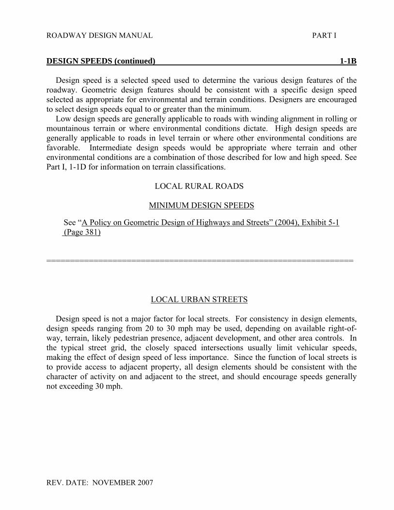
DESIGN SPEEDS (continued) 1-1B
Design speed is a selected speed used to determine the various design features of theroadway. Geometric design features should be consistent with a specific design speedselected as appropriate for environmental and terrain conditions. Designers are encouragedto select design speeds equal to or greater than the minimum.
Low design speeds are generally applicable to roads with winding alignment in rolling ormountainous terrain or where environmental conditions dictate. High design speeds aregenerally applicable to roads in level terrain or where other environmental conditions arefavorable. Intermediate design speeds would be appropriate where terrain and otherenvironmental conditions are a combination of those described for low and high speed. SeePart I, 1-1D for information on terrain classifications.
LOCAL RURAL ROADS
MINIMUM DESIGN SPEEDS
See “A Policy on Geometric Design of Highways and Streets” (2004), Exhibit 5-1 (Page 381)
=================================================================
LOCAL URBAN STREETS
Design speed is not a major factor for local streets. For consistency in design elements,design speeds ranging from 20 to 30 mph may be used, depending on available right-of-way, terrain, likely pedestrian presence, adjacent development, and other area controls. Inthe typical street grid, the closely spaced intersections usually limit vehicular speeds,making the effect of design speed of less importance. Since the function of local streets isto provide access to adjacent property, all design elements should be consistent with thecharacter of activity on and adjacent to the street, and should encourage speeds generallynot exceeding 30 mph.

ROADWAY DESIGN MANUAL PART I
REV. DATE: NOVEMBER 2007
DESIGN SPEEDS (continued) 1-1B
RURAL COLLECTORS
MINIMUM DESIGN SPEEDS
See “A Policy on Geometric Design of Highways and Streets” (2004), Exhibit 6-1. (Page 422)
=================================================================
URBAN COLLECTORS
MINIMUM DESIGN SPEEDS
Design speed is a factor in the design of collector streets. For consistency in design,design speed of 30 mph or higher should be used for urban collector streets, depending onavailable right-of-way, terrain, adjacent development, likely pedestrian presence, and othersite controls.
In the typical urban street grid, closely spaced intersections often limit vehicular speedsand thus make the consideration of design speed of lesser significance. Nevertheless, thelonger sight distances and curve radii commensurate with higher design speeds result insafer highways and should be used to the extent practical.
=================================================================
RURAL ARTERIALS
MINIMUM DESIGN SPEEDS
Rural arterials should be designed with design speeds of 40 to 75 mph depending onterrain, driver expectancy and, in the case of reconstruction projects, the alignment of theexisting facility. Design speeds in the higher range -60 to 75 mph- are normally used inlevel terrain, design speeds in the midrange -50 to 60 mph- are normally used in rollingterrain, and design speeds in the lower range -40 to 50 mph- are used in mountainousterrain.
=================================================================

ROADWAY DESIGN MANUAL PART I
REV. DATE: NOVEMBER 2007
DESIGN SPEEDS (continued) 1-1B
URBAN ARTERIALS
MINIMUM DESIGN SPEEDS
Design speeds for urban arterials generally range from 30 to 60 mph. Lower speeds applyin more developed areas and in central business districts, while higher design speeds aremore applicable in outlying suburban and developing areas.
=================================================================
URBAN AND RURAL FREEWAY
MINIMUM DESIGN SPEEDS
As a general consideration, the design speed of urban freeways should not be so high asto exceed the limits of prudent construction, right-of-way, and socioeconomic costs.However, this design speed should not be less than 50 mph. Wherever this minimum designspeed is used, it is important to have a properly posted speed limit, which is enforced duringoff-peak hours. On many urban freeways, particularly in developing areas, a design speed of 60 mph orhigher can be provided with little additional cost. In addition, the corridor of the main linemay be relatively straight with the character of the roadway and location of interchangespermitting an even higher design speed. Under these conditions, a design speed of 70 mphis desirable because higher design speeds are closely related to the overall quality and safetyof a facility. For rural freeways, a design speed of 70 mph should be used. In mountainousterrain, a design speed of 50mph to 60 mph, which is consistent with driver expectancy,may be used.
=================================================================

ROADWAY DESIGN MANUAL PART I
REV. DATE: NOVEMBER 2007
DESIGN SPEEDS (continued) 1-1B
INTERSTATES
MINIMUM DESIGN SPEEDS
See A Policy on Design Standards - Interstate System, AASHTO, July 1991, Page 3.
=================================================================
TRAFFIC VOLUMES 1-1C
Traffic volumes are a major factor in selecting design criteria. All design criteria is basedon a Design Hourly Volume (DHV) or annual Average Daily Traffic (ADT). Sometimes onminor low volume roads, the Average Daily Traffic (ADT) is the only traffic volume listedin the planning report. In this case, the ADT is used as the design basis. However, on mostmajor highways, the design is based on a design hourly volume (DHV). The DHV is basedon the 30th highest hourly volume. The design year is listed in the planning report and isusually either ten or twenty years beyond the beginning of construction.
If projects are delayed, the design year traffic should be updated. Design year traffic thatis 17 years or less from the beginning of construction should be updated to twenty years.For example, a project has a twenty year design period and is scheduled to be let in 1998.The design year traffic listed in the planning document is 2015. The traffic volumes shouldbe updated to the year 2018. These traffic updates should occur as necessary at thebeginning of the preliminary design, right of way plans, and final plans.

ROADWAY DESIGN MANUAL PART I
REV. DATE: NOVEMBER 2007

ROADWAY DESIGN MANUAL PART I
REV. DATE: NOVEMBER 2007
TRAFFIC VOLUMES (continued) 1-1C
The Project Development and Environmental Analysis Branch is in agreement with thisconcept. The actual conversion from ADT to DHV is accomplished by the usual method ofapplying the appropriate DIR and DHV factors. Please note that this method results indirectional peaks for all movements simultaneously and may not be appropriate for allcases, such as restricted or urban areas. In restricted or urban areas A.M. and P.M. or a 60%vs. 40% direction may be required.
COMPLETED DHV CONVERSION
This procedure cannot be used when the given one-way daily volumes are excessivelyunbalanced. When this is the case, the one-way hourly volume will be determined bydoubling the traffic volume and then applying the appropriate directional and hourly factors.The designer must make the determination when to apply this procedure.
As a final note, be sure to use the proper DHV factors. They should be provided with thetraffic estimates from the Project Development and Environmental Analysis Branch. If youdo not receive them, ask for them. In the event the Project Development and EnvironmentalAnalysis Branch cannot furnish the DHV Factors, you can obtain them from Figure 4.9(page 85) of the Transportation and Traffic Engineering Handbook located in the SpecialServices Group, of the Alternative Delivery Unit.

ROADWAY DESIGN MANUAL PART I
REV. DATE: NOVEMBER 2007
TRAFFIC VOLUMES (continued) 1-1C
NOTE: GENERAL DEFINITIONS FOR MEASURE OF TRAFFIC VOLUME
AVERAGE DAILY TRAFFIC (ADT)
The most basic measure of the traffic demand for a highway is the Average Daily Traffic(ADT) volume. The ADT is defined as the total volume during a given time period (inwhole days), greater than 1 day and less than 1 year, divided by the number of days in thattime period. The current ADT volume for a highway can be readily determined whencontinuous traffic counts are available. When only periodic counts are taken, the ADTvolume can be estimated by adjusting the periodic counts according to such factors as theseason, month, or day of week.
DESIGN YEAR ADT
Design Year ADT is the general unit of measure for projected Average Daily Traffic(ADT) to some future design year. Usually, the Design Year is about 20 years from the dateof beginning construction but may range from the current year to 20 years depending on thenature of the improvement.
See “A Policy on Geometric Design of Highways and Streets” (2004), Ch.2. Also seeChapter 4 of this manual.
TERRAIN CLASSIFICATIONS 1-1D
For design purposes, three terrain classifications are utilized in North Carolina. Theseclassifications have an affect on the design criteria and will be reflected in the designcharts. They are as follows:
Level: In level terrain, highway sight distances, as governed by both horizontal andvertical restrictions, are generally long or can be designed to be so withoutconstruction difficulties or major expense. In level terrain, the slope isconsidered to range from 0% to 8%. Any reference to a slope shall mean therise and fall on the grade measured both parallel and perpendicular to thecenterline.
Rolling: In rolling terrain, natural slopes consistently rise above and fall below thehighway grade line, and occasional steep slopes offer some restriction tonormal highway horizontal and vertical roadway alignment. In rolling terrain,the slope is considered to range from 8.1% to 15%.

ROADWAY DESIGN MANUAL PART I
REV. DATE: NOVEMBER 2007
TERRAIN CLASSIFICATIONS (continued) 1-1D
Mountainous: In mountainous terrain, longitudinal and transverse changes in the elevationof the ground with respect to a highway are abrupt. Benching and side hillexcavation is frequently needed to obtain acceptable horizontal and verticalalignment. In mountainous terrain, the slope is considered to range over 15%.
See “A Policy on Geometric Design of Highways and Streets” (2004), Ch.3.
When a terrain classification is chosen, geographical locations should not be the majorfactor. For example, a segment of road west of Asheville may have land characteristics ofroads in level or rolling terrain.
PROJECT COST REDUCTION GUIDELINES 1-1E
The primary objective of highway design is to design a safe, functional, aestheticallyappearing facility which is adequate for the design traffic volumes, for the minimum lifecycle costs. These guidelines suggest possible design changes to help reduce project costs.The suitability of each suggested change should be evaluated within the context of theprimary objective of highway design.
(1) Avoid overdesign.
Consider using minimum design criteria where doing so will not significantlycompromise safety or function.
(2) Cross Section
a) Median width - Use the minimum width that is compatible with the type offacility, the needs of projected traffic, positive drainage requirements, andmedian crossover design.
b) Lane width - See “A Policy on Geometric Design of Highways and Streets”
(2004), Exhibit 5-5, for desirable lane widths. Arterial lane widths may bereduced to 11 ft. when restrictive or special conditions exist. Less thandesirable lane widths may remain on reconstructed highways where alignmentand safety records are satisfactory.
c) Shoulder width - See Part I, Chapter 1-4 of this manual, for minimumshoulder widths. Partial width shoulders may be considered where full widthshoulders are unduly costly, as in mountainous terrain.

ROADWAY DESIGN MANUAL PART I
REV. DATE : 01/02/02
PROJECT COST REDUCTION GUIDELINES (continued) 1-1E
d) Roadway ditch - See part I, Chapter 1-2A, Figure 1, of this manual, forstandard methods of designing roadway ditches. Flatter or steeper slopes thanthose shown in Figure 1 may be warranted by project specific soil conditions,accident history, or requirements for balancing earthwork.
e) Ramp widths - The standard ramp pavement width is 14 ft. 12 ft. ramppavement width may be used if the full usable width of right shoulder is to bepaved. (See Paved Shoulder Policy - Part I, Chapter 1-4O)
f) Y-lines - Select Y-line pavement width and intersection radii which isappropriate for Y-line traffic volumes and characteristics, and compatible withthe existing Y-line cross-section.
(3) Earthwork
Earthwork is one of the highest cost items on projects; therefore, every effortshould be made to reduce and balance earthwork.
a) The steepest slopes practical should be used while considering soil conditions,safety requirements, constructability and maintenance.
b) Alignment - To help reduce earthwork, give careful attention to the selection
of horizontal and vertical alignments. Attempt to balance cut and fill sections,and avoid areas with poor soil conditions. The Project Engineer and ProjectDesign Engineer should both carefully review project alignments.
c) Use waste to flatten slopes, build false cuts, etc., to improve safety and
eliminate guardrail, and eliminate the need for waste pits. (Where possible,use unsuitable material to flatten slopes.)
d) Utilize cost effective analysis to determine if it is more economical to flatten
slopes or use guardrail. (Consider R/W cost, and the cost of providing wasteareas.)
e) Preliminary grades are usually based on contour maps and errors of 5 feet in
elevation are possible. When beginning right of way plans, the preliminarygrades should be reviewed and refined so they will be accurate and costeffective.

ROADWAY DESIGN MANUAL PART I
REV. DATE : 01/02/02
PROJECT COST REDUCTION GUIDELINES (continued) 1-1E
(4) Right of Way
a) Where feasible, use temporary easements rather than purchasing property.This reduces right of way costs and the unnecessary taking of property. SeePart II, Chapter 9-4 of this Manual.
b) Consider using an "L" or "Tee" type turn around instead of a circular
cul-de-sac to save pavement cost and reduce right of way on roads beingdead-ended.
c) Consider reducing commercial channelization to that required for sight
distance and maintenance of roadway.
(5) Drainage
a) Review drainage and have Hydraulics Unit recheck whenever it appearschanges could be made to reduce cost. Use stone lined ditches where possiblein lieu of paved ditches.
b) Reduce length of paved ditch or stone lined ditches where possible. c) In interchange areas, look closely at drainage to see if grading adjustments
could simplify drainage and reduce drainage items.
(6) Pavement Design
a) Use pavement components, which give a reduction in number of layers andconstruction operations.
b) All pavement designs including mainline, Y-lines, ramps, loops and detours
should be obtained from the Pavement Management Unit.
(7) General
a) Carefully review high cost items (bridges, culverts, barriers, special designs,etc.) to reduce or eliminate where possible.

ROADWAY DESIGN MANUAL PART I
REV. DATE: NOVEMBER 2007
SHOULDERS 1-4
Paved or unpaved shoulders will be based on traffic volume warrants and the pavementcomposition of the adjacent pavement utilized for the mainline, ramp and etc. Figure 1-4Foutlines typical paved shoulder construction. The pavement design report will specify thetype of paved shoulder to construct. All utility poles shall be placed outside the Clear Zoneas defined by the 2002 Roadside Design Guide.
SHOULDER WIDTHS ON MAINLINE 1-4A
See 1-4B (Figure 1) for usable and graded shoulder widths for local, collector, arterial,interstate and freeway roads.
NOTE: Due to frequent on-shoulder parking and other special design features,Subdivision Roads and Streets shall conform to NCDOT Minimum ConstructionStandards For Subdivision Roads and may not conform to the above designguidelines.
USABLE AND GRADED SHOULDERS 1-4B
See 1-4B (Figure 1) for usable and graded shoulder widths and their relationship to theoverall shoulder width. Shoulders shall not exceed these values unless specified otherwisein the Planning Report or unless approved by the Assistant State Roadway Design Engineer.
NOTE: These guidelines apply to new construction, not 3-R projects.
When guardrail is required on a project, additional shoulder width, as noted in Figure 1,is needed for guardrail installation and clearance. At times, this added shoulder width iscontinued throughout the project for uniformity. As a cost-reduction measure, normalshoulder widths should be specified where guardrail is not required and then transitioned towider shoulders where guardrail is required. Engineering judgement would be used inconsidering this method by taking into account the length of the project and the amount ofguardrail required.

DESIGN YEAR
*
*
MINIMUM SHOULDER
WITHOUT GUARDRAIL WITH GUARDRAIL
** WHEN GUARDRAIL IS WARRANTED, THE MINIMUM SHOULDER WIDTH
IS INCREASED BY 3’-0" AS SHOWN IN THE ABOVE DIAGRAM.
M M
TOTAL
SHOULDER
3’-0"
**
FIGURE 1
**
**
1-4B
F-1
SHOULDER WIDTHS
LOCALS AND COLLECTORS
M = MINIMUM SHOULDER
EOT = EDGE OF TRAVEL LANE
EOTEOT
WHEN GUARDRAIL IS WARRANTED, THE MINIMUM OFFSET FROM THE EDGE
OF THE TRAVEL LANE TO THE FACE OF THE GUARDRAIL IS 4’-0".
WHERE ENVIORONMENTAL CONSTRAINTS ALLLOW, 6-FOOT SHOULDERS SHOULD
BE UTILIZED RATHER THAN THE 5-FOOT SHOULDERS.
SEE "A POLICY ON GEOMETRIC DESIGN OF HIGHWAYS AND STREETS", (2001)
EXHIBITS 5-5 AND 6-5.
2’ 5’ 6’ 8’
LOCALS
COLLECTORS
AND
ADT
UNDER
400
400 -
1500
1501 -
2000
OVER
2000
IN THE DESIGN OF LOCALS AND COLLECTORS, USE
THE FOLLOWING MINIMUM SHOULDER WIDTHS.
Revision Date 10/20/06
Revision No. 4

1-4B
F-1A
SHOULDER WIDTHS
DESIGN YEAR
USABLE SHOULDER
WITHOUT GUARDRAIL WITH GUARDRAIL
U
U
ARTERIALS, INTERSTATES, AND FREEWAYS
**
**
5’-0"
VAR.
U
U
U
4:1 ORFLATTER
1’-0"
3:1
2’-0"
2:1
3’-0"
1 1/2 : 1OR STEEPER
3’-0"
2’-0"
FIGURE 1A
U = USABLE SHOULDER
EOT = EDGE OF TRAVEL LANE
EOT
EOT
EOT
EOT
EOT
IN THE DESIGN OF ARTERIALS, INTERSTATES AND FREEWAYS,
USE THE FOLLOWING MINIMUM USABLE SHOULDER WIDTHS.
ADT
ARTERIALS 4’ 6’ 6’ 8’
2000
OVER
2000
1501 -1500
400 -
400
UNDER
NOTE: SEE " A POLICY ON GEOMETRIC DESIGN OF HIGHWAYS AND STREETS" (2001), EXHIBIT 7-3.
NOTE: SEE ARTERIAL MAP PROVIDED IN THIS MANUAL.
10’ ON FREEWAYS, EXPRESSWAYS, AND INTERSTATES AND
12’ ON FREEWAYS AND INTERSTATES WHEN TRUCK DHV EXCEEDS 500.
Revision Date 10/20/06
Revision No. 4

ROADWAY DESIGN MANUAL PART I
REV. DATE : NOVEMBER 2007
N.C. DOT PAVED SHOULDER POLICY 1-4C
The NCDOT Paved Shoulder Policy incorporates the findings of an in-depth study ofconstruction, maintenance, safety, operational and economic issues related directly to theusage of paved shoulders. The economics of providing a safe overall highway system werealso considered in determining an appropriate level of expenditure for this design feature.The resultant policy is a standardized method developed specifically for the purpose ofconsistently providing acceptable paved shoulder designs for each roadway classification.Engineering judgement may be used to determine the need for a higher type shoulder designthan is required by this policy on a case-by-case basis. Usage of paved shoulder widths inexcess of the requirements of this policy must be approved by the State Roadway DesignEngineer. See 1-4O, and 1-4O, Figure 1, of this manual for additional information.
SHOULDER WIDTH ON LOOPS 1-4D
Inside Shoulder – 14′ Des. 12′ Min. (Right Side of Traffic)Outside Shoulder – 12′ Des. 10′ Min. (Left Side of Traffic)
If pavement widening is required, it shall be placed on the inside of the curve. The 2′-6″concrete curb and gutter is placed adjacent to the inside edge of pavement to controldrainage and reduce shoulder maintenance. See Chapter 8-1 of this manual for looppavement widths.
SHOULDER WIDTHS ON RAMPS 1-4E
Inside Shoulder – 12′ Des. 10′ Min. (Left Side of Traffic)Outside Shoulder – 14′ Des. 12′ Min. (Right Side of Traffic)
See Chapter 8-2 of this manual for ramp pavement widths.

ROADWAY DESIGN MANUAL PART I
REV. 1/02/02

PAVED SHOULDERS WITH RIGID PAVEMENT
EDGE OF
TRAVEL LANE 12" 6"
36" 12"
12"
4" DIA. PIPE
#57 STONE
CONCRETE
EDGE OF
TRAVEL LANE
2’ F.D.P.S.
12" 6"
36" 12"
12"
4" DIA. PIPE
#57 STONE
CONCRETE
10’ PAVED SHOULDER
6" ASPHALT
MATERIAL
BASE MATERIAL
CONCRETE
CONCRETE
FABRIC
FABRIC
EDGE OF
TRAVEL LANE 12"
36" 12"
12"
4" DIA. PIPE
#57 STONE
BASE MATERIAL
FABRIC
CONCRETE
4’ OR 10’ PAVED SHOULDER
F.D.P.S. - FULL DEPTH PAVED SHOULDER
PADL - PERMEABLE ASPHALT DRAINAGE LAYER
1 - 4G
EARTH
MATERIAL
EARTH
MATERIAL
EARTH
MATERIAL
24"
4" PADL OR ACBC
1" SURFACE COURSE
4" PADL OR ACBC
1" SURFACE COURSE
4" PADL OR ACBC
ACBC - ASPHALT CONCRETE BASE COURSE
1" SURFACE COURSE
CONCRETE
& ASPHALT
2’ OR 10’ F.D.P.S.
ROADWAY DESIGN MANUAL PART 1
CONCRETE
SHOULDER
REV. DATE: NOVEMBER, 2007

ROADWAY DESIGN MANUAL PART I
REV. DATE: NOVEMBER 2007
MEDIAN SLOPES (continued) 1-6F NOTE: 1. For projects with flat grades, variable median slopes that increase the
ditch grade to improve longitudinal drainage capability shall be considered.
2. Ditch slopes should meet "Roadside Design Guide" criteria for preferred ditch sections.
PROPOSED MEDIANS
(New Roadways) When determining the width and maximum (steepest) slopes of a proposed median, consideration shall be given to the following design criteria: A - Design Year Traffic Volume and Level of Service B - Design Speed C - Clear Zone Requirements "Roadside Design Guide" D - Adequate Drainage of the Pavement Structure When optimum median width has been established, the ditch slopes should be set as shown in Part 1-2B, Figure 1 thru 4. In no case shall the slopes be steeper than those specified for existing medians. NOTE: The important hydraulic role of the median ditch in removing water from the
roadway surface and protecting the integrity of the pavement structure cannot be overly stressed. In order to provide adequate drainage, shoulder drains and underdrains shall be considered along with median slopes, which will adequately drain both the roadway surface and subgrade. The Pavement Management Unit will make recommendations to the Design Engineer on a project by project basis.

ROADWAY DESIGN MANUAL PART I
REV. 4REV. 12/01/05
EARTH BERM MEDIAN PIER PROTECTION 1-6G
With median widths 70′ and less, Pier Protection shall be provided. An earth berm,guiderail, or guardrail shall be placed as pier protection, when the median width is 70′.When earth berms are placed, pier footings shall be designed accordingly and slopeprotection placed according to the applicable standards. An earth berm for pier protection isdesirable for medians 70′ wide (Roadway Standard Drawings, Std. No. 225.08). If the earthberm is not feasible or cost effective, guardrail or guiderail should be utilized.
Median widths over 80′ require no impact protection. For additional information, see17/2 in the Policy and Procedure Manual. See Roadway Standard Drawings, Std. No.225.08.
MEDIAN DESIGN ON STRUCTURES 1-6H
See Part I, Chapter 6-4 of this manual.
MEDIANS ON -Y- LINES 1-6I
The type of median to be constructed in interchange areas shall be determined early inthe design stage. If raised islands are proposed across the structure, this shall be shown onthe structure recommendations. See Part I, Chapter 6-6 of this Manual.
MEDIAN CROSSOVER GUIDELINES 1-6J
Median Crossover Guideline Statement
Median divided facilities provide the benefits of separating opposing travel lanes,controlling left turn conflicts, allowing a recovery area for out of control vehicles, and aspace for future travel lanes. Research data also concludes that the median divided facilitiesimprove traffic flow (travel speeds), traffic operations (reduces congestion), and trafficsafety (lower crash rates), when compared to non-divided facilities. Median crossovers maybe necessary on median divided facilities) that are not fully access controlled) to allow foradditional turning and through movements. A median crossover is defined as anyconnections of the opposing travel lanes that crosses the median of a divided highway.Median crossover includes directional crossovers, U-turns or all-movement crossovers.
Placement of crossovers should be considered carefully since crossovers introduce conflictpoints along a divided facility and thus may reduce the safety and capacity of the mediandivided facility. Therefore, it is important to follow these guidelines when considering theaddition of median crossovers. The following guidelines have been developed as a guidefor design engineers, traffic engineers, and field personnel when considering the placementor addition of median crossovers. The median crossover guidelines shall be used for allnew crossovers, even in the cases where adjacent crossovers were approved under previousguidelines.

ROADWAY DESIGN MANUAL PART I
REV. DATE: NOVEMBER 2007
RAISED ISLANDS 1-8
Flush pavement with markings is often more desirable than raised islands especiallywhere speeds exceed 45 mph. However, when it has been determined that raised islandswill be required, both construction and maintenance costs should be considered.
In most instances, monolithic construction should be utilized on islands up to 16′ in widthdue to greater cost- effectiveness, ease and speed of placement, and reduced futuremaintenance requirements. For widths greater than 16′, cost-comparisons should be madebetween monolithic islands and grass covered islands with curb and gutter to determine themost cost-effective design. In making the determination, consideration should be given tothe projected maintenance cost-savings of the monolithic island and the traffic operationrequirements for the particular project.
Full depth pavement is normally utilized under the narrower bulb-type islands and underraised median islands when traffic operations during construction will require vehiculartraffic in the median area. When traffic operations are not required in the median, it is moreeconomical to place the monolithic island on a compacted aggregate base.
In special cases, grassed, landscaped, or covered islands may be used in urban orresidential areas where recommended by the Division Engineer and approved by theRoadside Environmental, Construction, and Maintenance Units. These islands provide anaesthetically pleasing appearance with all surroundings, but only when well maintained.The construction costs of grassed or landscaped islands are considerably lower than those ofmonolithic islands. However, the greatly increased maintenance costs and the increaseddanger involved in maintenance operations prevents these islands from normally beingjustified except under unusual circumstances.
When any type of concrete curb is proposed on a project and it is not in accordance withRoadway Standard Drawings, Std. No’s. 846.01, 852.01, and 852.02, a special detail shallbe shown in the plans. The Plans and Standards Engineer in Project Services shall beconsulted prior to drawing any details. This section has developed several concrete curbconfigurations that provide satisfactory results. For raised island treatment on structures,see this Manual Part I, Chapter 6-6G.

ROADWAY DESIGN MANUAL PART I
REV. DATE: NOVEMBER 2007
STANDARD CONCRETE CURB AND GUTTER 1-9 See Roadway Standard Drawings, Std. No. 846.01. All utility poles shall be placed outside the Clear Zone as defined by the 2002 Roadside Design Guide. For Curb and Gutter where posted speed is 45 MPH or less, all utility poles shall be placed outside the Clear Zone where practicable. If this cannot be achieved due to right of way restraints, the utility pole may be placed a minimum of 12 feet from the face of the curb. All utility poles that are placed closer than 12 feet shall be breakaway poles. See Figure 1-7D, F-4 for Detail. STEPS 1-10 The type of steps to construct shall be determined by the Division Engineer. When existing steps are being disturbed, it is customary to replace the same type of step. For additional information, see Roadway Standard Drawings, Std. No’s. 844.01 and 844.02. SPIRAL CURVES 1-11 Spiral curves are required on interstates, freeways, expressways and all major arterials. Where terrain and topography restrict their use, the Project Engineer will have the option to delete spirals on collector roads, local roads and streets, and on minor arterials with a design speed less than 45 mph. Spirals (including tangent runout) should be avoided on bridges and in all cases should not begin or end on the bridge. In cases where spirals are absolutely required on bridges, the increment spacing should be equally spaced across the entire length of the bridge.
There are several methods for computing the length of Spirals. The recommended method for determining spiral lengths is to use A POLICY ON GEOMETRIC DESIGN OF HIGHWAYS AND STREETS (2004), Chapter 3. COMPOUND SPIRALS 1-11A Compound Spirals should be used between two curves if the radius of one curve is twice the radius of the second curve. Compound Spirals should also be used on all interstates, freeways, expressways, arterials, and on ramps in interchange areas as the preferred method to change superelevation rates.

ROADWAY DESIGN MANUAL PART I
REV. DATE : NOVEMBER 2007
DESIGN CONTROL FOR VERTICAL CURVES 1-12Design Controls for Crest Vertical Curves-Open Road Conditions
See “A POLICY ON GEOMETRIC DESIGN OF HIGHWAYS AND STREETS ” (2004),Exhibits 3-75 and 3-76
Design Controls for Sag Vertical Curves-Open Road ConditionsSee “A POLICY ON GEOMETRIC DESIGN OF HIGHWAYS AND STREETS ” (2004),Exhibits 3-78 and 3-79.
Design Controls for Crest Vertical Curves Based on Passing Sight DistanceSee “A POLICY ON GEOMETRIC DESIGN OF HIGHWAYS AND STREETS ” (2004),Exhibit 3-77.
MINIMUM WIDTH OF TRAVELED WAY AND SHOULDERS 1-13Minimum Width of Traveled Way and Shoulders for Local Roads and Streets
See “A POLICY ON GEOMETRIC DESIGN OF HIGHWAYS AND STREETS ” (2004),EXHIBIT 5-5.
Minimum Width of Traveled Way and Shoulders for Collector Roads and Streets
See “A POLICY ON GEOMETRIC DESIGN OF HIGHWAYS AND STREETS ” (2004),EXHIBIT 6-5.
Minimum Width of Traveled Way and Usable Shoulders for Rural Arterials
See “A POLICY ON GEOMETRIC DESIGN OF HIGHWAYS AND STREETS ” (2004),EXHIBIT 7-3.

ROADWAY DESIGN MANUAL PART I
REV. DATE : NOVEMBER 2007
MAXIMUM GRADES 1-14Maximum Grades for Rural and Urban Freeways.
See “A POLICY ON GEOMETRIC DESIGN OF HIGHWAYS AND STREETS ” (2004),EXHIBIT 8-1.
Maximum Grades for Rural Arterials
See “A POLICY ON GEOMETRIC DESIGN OF HIGHWAYS AND STREETS ” (2004),EXHIBIT 7-2.
Maximum Grades for Urban Arterials
See “A POLICY ON GEOMETRIC DESIGN OF HIGHWAYS AND STREETS ” (2004),EXHIBIT 7-10.
Maximum Grades for Rural Collectors
See “A POLICY ON GEOMETRIC DESIGN OF HIGHWAYS AND STREETS ” (2004),EXHIBIT 6-4.
Maximum Grades for Urban Collectors
See “A POLICY ON GEOMETRIC DESIGN OF HIGHWAYS AND STREETS ” (2004),EXHIBIT 6-8.
Maximum Grades for Local Rural Roads
See “A POLICY ON GEOMETRIC DESIGN OF HIGHWAYS AND STREETS ” (2004),EXHIBIT 5-4.

ROADWAY DESIGN MANUAL PART I
REV. DATE : NOVEMBER 2007
SUPERELEVATION RATES 1-15
Minimum Superelevation Runoff and Tangent Runout Lengths
See “A POLICY ON GEOMETRIC DESIGN OF HIGHWAYS AND STREETS ” (2004),EXHIBIT 3-29.
Minimum Radius for Design of Rural Highways, Urban Freeways, and High-SpeedUrban Streets Using Limiting Values of (e) and (f).
See “A POLICY ON GEOMETRIC DESIGN OF HIGHWAYS AND STREETS ” (2004),EXHIBIT 3-14.
Diagrammatic Profiles Showing Methods of Attaining Superelevation
See “A POLICY ON GEOMETRIC DESIGN OF HIGHWAYS AND STREETS ” (2004),EXHIBIT 3-37.

ROADWAY DESIGN MANUAL PART I
REV. DATE : NOVEMBER 2007
SUPERELEVATION RATES (continued) 1-15
If maximum superelevation rates are used other than those shown the guidelines, it shall bediscussed with the appropriate Assistant State Roadway Design Engineer.
SUPERELEVATION GUIDELINES
TYPE OF ROADWAY LOCATION & CONDITIONS SUPERELEVATION (1)
Interstates & Freeways • Statewide
.08 or .10 (2)
Ramps & Loops • Statewide .08
Flyovers
(Directional ramps with bridges)
• Statewide .06
Arterials &Rural Collectors
• Statewide• Limited Access
.08
Arterials & UrbanCollectors with 60 mph designspeed or greater
• Statewide• Partial or no control of
access.06
Urban Collectorswith 50 mph or less designspeed
• Statewide• Curb & Gutter or shoulders
with driveways.04
Bridge replacementprojects, locals, & SecondaryRoads
• Statewide.04 or .06
Choose table that fitscharacteristics of area
(1) Refers to particular design superelevation table shown in the 2004 AASHTO“Green Book” ( pages 156 to 165) that the designer should use.
(2) Don’t use in locations susceptible to icy conditions.
Bridges – it is desirable to use a degree of curve that the superelevation will not exceed .06 on anybridge.

ROADWAY DESIGN MANUAL PART I
REV. DATE : NOVEMBER 2007
HYDROPLANNING AWARENESS OUTLINE 1-16
Hydroplaning Awareness Outline
I. Contributing FactorsA. Water film and thicknessB. Pavement cross slope and longitudinal slopeC. Pavement roughnessD. Vehicle speedE. Tire condition and so forth
II. Identification of Problem AreasA. Existing conditions
1. Skid testing2. Accident Reports3. Visual Observation4. Reports from Department personnel and citizens
B. Proposed/Design Condition 1. Design Analysis
2. Accident Reports and so forth upon project completion (see Existing)
III. Remedial and CountermeasuresA. Existing Condition
1. Improve pavement surface – open graded asphalt friction courses2. Improved surface water removal
a. Improved drainage systemsb. Improved longitudinal and transverse pavement and shoulder
slopes3. Warning signs
B. Proposed/Design Condition – Roadway Design5. Typical section
a. Pavement Cross Slopeb. Shoulder cross slopec. Rooftop section
6. Gradesa. Minimum of 0.3% (tangent and along VC)b. Vertical Curves
1. Sag (K factors greater than 167 can create drainageproblems, AASHTO p 286)
2. Crest (avoid 0.3% except within 50 ft. of high or low point)7. Superelevation
a. Resolve SE about centerline instead of median EOPb. c. Avoid long SE transition areas
8. Combination of the above factors
ROADWAY DESIGN MANUAL PART I
REV. DATE : NOVEMBER 2007
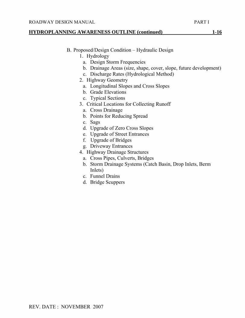
HYDROPLANNING AWARENESS OUTLINE (continued) 1-16
B. Proposed/Design Condition – Hydraulic Design1. Hydrology
a. Design Storm Frequenciesb. Drainage Areas (size, shape, cover, slope, future development)c. Discharge Rates (Hydrological Method)
2. Highway Geometrya. Longitudinal Slopes and Cross Slopesb. Grade Elevationsc. Typical Sections
3. Critical Locations for Collecting Runoffa. Cross Drainageb. Points for Reducing Spreadc. Sagsd. Upgrade of Zero Cross Slopese. Upgrade of Street Entrancesf. Upgrade of Bridgesg. Driveway Entrances
4. Highway Drainage Structuresa. Cross Pipes, Culverts, Bridgesb. Storm Drainage Systems (Catch Basin, Drop Inlets, Berm
Inlets)c. Funnel Drainsd. Bridge Scuppers

ROADWAY DESIGN MANUAL PART I
REV. DATE : NOVEMBER 2007
DESIGN CONTROLS FOR STOPPING SIGHT DISTANCEON HORIZONTAL CURVES 1-17
See “A POLICY ON GEOMETRIC DESIGN OF HIGHWAYS AND STREETS ” (2004),EXHIBITS 3-57 and 3-58.
Passing Sight Distance for Design of Two-Lane Highways
See “A POLICY ON GEOMETRIC DESIGN OF HIGHWAYS AND STREETS ” (2004),EXHIBIT 3-7.
DESIGN VALUES FOR TRAVELED WAY PAVEMENT WIDENINGAND WIDTHS ON OPEN HIGHWAY CURVES AND TURNING ROADS 1-18
See “A POLICY ON GEOMETRIC DESIGN OF HIGHWAYS AND STREETS ” (2004),EXHIBITS 3-51, 3-52, 3-53, 3-54 AND 3-55.
MINIMUM TURNING PATHS FOR DESIGN VEHICLES 1-19
See “A POLICY ON GEOMETRIC DESIGN OF HIGHWAYS AND STREETS ” (2004),EXHIBITS 2-3 thru 2-23.


ROADWAY DESIGN MANUAL PART 1
REV. DATE : NOVEMBER 2007
CHAPTER TWO
MISCELLANEOUS DESIGN CRITERIA
GLARE SCREENS 2-1
Background: The following information is from "Evaluation of Glare Screens-FinalReport, November 2, 1988,” prepared by Ashley B. Vaughn.
A copy of this report is on file in the Roadway Design Library and in the SpecialServices Group, Alternative Delivery Unit.
Additional information on glare screens mounted on guardrail can be found in theRoadway Standard Drawings, Std. No. 866.05.
I. Criteria for Use of Glare Screens
a. Glare screens should be considered in the median on multilane highways, ininterchange areas, and where service roads are in close proximity to major arterials.
b. Opposing traffic with 20' or less of separation should be highly considered forusing a glare screen.
c. Widths of 21' to 50' should be considered on a project by project basis andjustified using the following criteria:
New FacilitiesVertical and horizontal alignmentTraffic volumesField review of graded roadway
Existing FacilitiesAccident experience
a. Day/night ratio of accidentsb. Age of drivers in night accidentsc. Unusual distribution by type of accident
Day/night traffic volumesPublic inputVertical and horizontal alignmentMeasure of glare (Use Pritchad Photometer)
d. Traffic separated by 50′ or more, will not need glare screens.

ROADWAY DESIGN MANUAL PART 1
REV. DATE : NOVEMBER 2007
GLARE SCREENS (continued) 2-1
e. Normal height should be 50″ and up to 80″ in sag verticals.
f. Cutoff angle for opposing highlight glare for screens on tangent alignments istwenty degrees (20°). The cutoff angle for screens on horizontal curves should be twentydegrees (20°) plus degree of curvature.
II. Types of Glare Screens
a. Type I - A continuous screen that is essentially opaque to light from all angles.
b. Type II - A continuous screen of an open material that is opaque to light at anglesto about 20 degrees and increasingly transparent beyond 20 degrees.
c. Type III - Individual elements positioned to block light at angles from 0 degrees to20 degrees. Beyond 20 degrees visibility is clear between the elements.
The following types of glare screens are recommended:
PlantsExtended Concrete Barrier½'' Mesh Chain Link Fence (Vinyl Coating Optional)Modular Guidance System
The State Roadway Design Engineer’s approval will be required for any use of glarescreen in areas other than interchanges or in areas in the 21′ to 50′ width. The submittalshould include drawings and justifications.
CLIMBING LANES 2-2
A climbing lane is the response to the increasing amount of traffic delays and the numberof serious crashes occurring on grades due to heavy loaded and slow moving vehicles. Consideration should be done during the original construction planning stage and onSafety Improvement Projects.
Criteria for recommending and designing climbing lanes is outlined in A POLICY ONGEOMETRIC DESIGN OF HIGHWAYS AND STREETS (2004), ch. 3. and the HighwayCapacity Manual, Chapter Three.

ROADWAY DESIGN MANUAL PART 1
REV. DATE : NOVEMBER 2007
CLIMBING LANES (continued) 2-2
Report No. FHWA-IP-88-015 Grade Severity Rating System (GSRS) can be used todetermine the maximum safe descent speeds for trucks according to weight and todetermine the need for an auxiliary lane.
Additional information on climbing lanes can be found in the FHWA Report: “NewMethods for Determining Requirements for Truck-Climbing Lanes” located in the RoadwayDesign Library and/or Alternative Delivery Library.
The locations proposed by the Project Engineer shall be discussed with the AssistantState Roadway Design Engineer. Justification studies and cost estimates will be requiredwhen the Project Engineer proposes climbing lanes.
PEDESTRIAN OVERPASSES 2-3
Pedestrian overpasses should be included in the environmental document for the project.If the potential need for the overpass is determined during the design phase of the project,then a request and justification should be made to the Project Development andEnvironmental Analysis Branch. The design of pedestrian overpasses should be submittedto the Federal Highway Administration and/or the Structure Design Unit as a structurerecommendation report using the A POLICY ON GEOMETRIC DESIGN OF HIGHWAYSAND STREETS (2004), CH. 4.
PEDESTRIAN UNDERPASSES 2-3A
Pedestrian underpasses should be considered where greenway facilities with pedestrianor bicycle use are existing or part of a planned system. Underpasses for greenways that aredetermined by using floodway maps and have not been designated as actual 'trails' can beconstructed if the city or county supplements the cost.
APPALACHIAN NATIONAL SCENIC TRAIL 2-4
Projects conflicting with the Appalachian National Scenic Trail should be included in theenvironmental document and any mitigation should be resolved at the planning stage. Trailcrossings of any project on new location will most likely require a grade separation.

ROADWAY DESIGN MANUAL PART 1
REV. DATE : NOVEMBER 2007
TRUCK ESCAPE RAMPS 2-5
Truck escape ramps have generally been used on long mountain grades in rural areas.They should also be considered in urban areas on steep, short grades where high truckvolumes are mixed with dense traffic and development. The urban areas have a higherprobability of fatalities or property damage than the rural areas especially if a stop conditionor turn occurs at the bottom of the grade.
It has also been suggested that an area should be provided at the top of the grade fortruckers to check their brakes, read any information available about the upcoming grade andshift to the correct gear for the downgrade.
Justification for truck escape ramps (TERs) involve several considerations and have notbeen formalized into specific warrants or processes. The principal factor for a TER need isdetermined by runaway accident experience. Site conditions such as grade length, percentof grade, a combination of horizontal alignment, and end-of-grade conditions weigh aboutequally.
Average daily traffic and percent trucks count about the same as site conditions.Although available right of way and topography are factors in site selection, they are notfactors in determining the need for a ramp.
The "Grade Severity Rating System (GSRS)" was developed to determine the maximumsafe speed for vehicles of different weights. It can also be used to establish the need andlocation for truck escape ramps by calculating the brake temperatures at ½ mile intervals ona grade. A computer program is available with this report.
Also, available in the Roadway Design Unit library is a very informative TransportationResearch Board publication:
"NCHRP Synthesis 178Truck Escape Ramps
A Synthesis of Highway Practice"
Limited information is also available in " A POLICY ON GEOMETRIC DESIGN OFHIGHWAYS AND STREETS (2004), CH. 3. Additional research information is availablein the Special Services Group, Alternative Delivery Unit.

ROADWAY DESIGN MANUAL PART 1
REV. DATE : NOVEMBER 2007
BARRIERS FOR NOISE ABATEMENT 2-6
Type I Projects
A Type I project is defined as a proposed Federal, or Federal-aid highway project forthe construction of a highway on new location or the physical alterations of an existinghighway which significantly changes either the horizontal or vertical alignment, or increasesthe number of through-traffic lanes. For Type I projects, the consideration of noiseabatement as a part of the highway construction project is mandatory if Federal-aid fundsare to be used and if a traffic noise impart is expected to occur.
Type II Projects
The only purpose of a Type II project is to construct noise abatement along anexisting roadway. NCDOT does not participate in retrofitting (Type II) projects.
Information for the Public and Local Officials:
In an effort to prevent future noise impacts on currently undeveloped lands, NCDOTwill use the following criteria:
A. The “Date of Public Knowledge” of the locations of a proposed highway projectwill be the approval date of CE’s, FONSI’s, ROD’s, or the Design PublicHearing, whichever comes later. After this date, the Federal/State governmentsare no longer responsible for providing noise abatement measures for newdevelopment for which building permits are issued within the noise impact areaof the proposed highway project.
B. For development occurring after this public knowledge date, it is theresponsibility of the local governing bodies to insure that noise compatibledesigns are utilized.
C. The date for determining when undeveloped land is “….planned, designed, andprogrammed…” for development will be the issuance of a building permit for anindividual site.
During the project development stage of a proposed highway project, informationalmeetings, both formal and informal, will be conducted to solicit comments, opinions, andconcerns from local officials and the public. A list of potentially affected areas andreasonable and feasible noise abatement measures will be developed by the Air and NoiseSections of the Project Development and Environmental Analysis Branch. These noisesensitive areas will be addressed in environmental documents prepared for the project.

ROADWAY DESIGN MANUAL PART 1
REV. DATE : NOVEMBER 2007
BARRIERS FOR NOISE ABATEMENT (continued) 2-6
Likely noise abatement measures will be presented and discussed at the Design PublicHearing. Following public comment, a Final Noise Report will be prepared. Abatementdesign measures deemed reasonable, feasible, and cost effective by staff Engineers, will beincorporated into this report and presented at a final meeting. In this forum, the opinions ofthe impacted residents are once again solicited to make a final determination on thereasonableness and feasibility of noise abatement.
The Department of Transportation will furnish the results of all highway traffic noiseanalyses to local government officials within whose jurisdiction a proposed highway projectis located. Specifically, environmental documents and design noise reports will containnoise contours and other pertinent design information. Local officials should coordinateand distribute this information to the local area affected. Following this procedure willencourage planners, developers, and affected communities to practice noise compatibledevelopment.
Sound and Noise
Sound is created when an object moves. This movement causes vibrations or wavesin air molecules like ripples on water. When vibrations reach our ears, we hear sound.Sound is quantified by a meter, which measures units called decibels (dB). For highwaytraffic noise, an adjustment or weighting of the highway and low-pitched sounds is made toapproximate the way that an average person hears sound. The adjusted sounds are called“A-weighted level” (dBA).
Noise is defined as unwanted or excessive sound. It is an undesirable by-product ofour modern way of life. Noise descriptors such as Leq are used to describe the time-varyingnature of noise. In noise abatement studies, Leq(h) or hourly equivalent sound level, isdefined as the constant, average sound level, which over a period of time contains the sameamount of sound energy as the varying levels of the traffic noise.
Noise Abatement / Impact Determination
In NCDOT highway projects, traffic noise abatement must be considered when eitherof the following two conditions exist.

ROADWAY DESIGN MANUAL PART 1
REV. DATE : NOVEMBER 2007
BARRIERS FOR NOISE ABATEMENT (continued) 2-6
A. The predicted design year noise levels approach or exceed those values shown for the appropriate activity category of the FHWA Noise Abatement.
Please note: NCDOT has defined approach values as being 1 dBA less than those in
the table and; the design year is 20 years after the start of construction.
B. The predicted design year noise levels substantially exceed existing noise level as defined below:
Existing (Leq(h) Increase ≤ 50 dBA > 15 dBA
> 50 dBA ≥ 10 dBA Please note: Depending on the existing noise levels, NCDOT uses both a 10 dBA increase to define a substantial increase. This sliding scale allows a greater increase at a lower existing noise level before a substantial increase is defined. A 10 dBA increase is judged by most people as a doubling of the loudness of the sound; a 15 dBA increase represents more than a doubling of the loudness.
Since NCDOT has no Type II program, noise abatement will generally not be considered for heavy maintenance, rehabilitation projects and existing conditions. Feasibility and Reasonableness After a determination has been made to consider noise abatement under A&B above, several factors including benefits, cost of abatement, and overall social, economic, and environmental effects should be examined to determine both the feasibility and reasonableness of constructing a noise abatement device.

ROADWAY DESIGN MANUAL PART 1
REV. DATE : NOVEMBER 2007
BARRIERS FOR NOISE ABATEMENT (continued) 2-6
A. Feasibility: Feasibility deals primarily with engineering considerations. The followingitems should be considered in order to determine feasibility.
1. Can a barrier be built given the topography of the location?2. Can a minimum 5 dBA reduction, but preferably 8 dBA or more, be
achieved for design receptors (first row receptors) given certain access,drainage, safety, or maintenance requirements?
3. Is other noise sources present in the area?4. Can noise reduction (insertion loss) provided by the wall be a minimum 5
dBA, but preferably 8 dBA or more, for design receptors (first rowreceptors) ?
5. Unless special conditions exist and effective abatement can be provided, itis not considered feasible to provide noise abatement on non-controlled orpartial access controlled facilities.
B. Reasonableness: Reasonableness is a more subjective criterion. It should show thatcommon sense and good judgement were used in arriving at a decision. A determinationof reasonableness should include the following:
1. Barrier Cost - the abatement measure should be cost effective. Costeffective is defined as $25,000 (construction cost) per effectively protected(5 dBA or more reduction) residence.
2. Barrier Height - The exposed height of a wall should not exceed amaximum of 25 feet.
3. Barrier Scale Relationship - It generally will not be reasonable to provideabatement unless the receptor is located a distance of four times the heightof the wall or more from the proposed wall. Noise walls have a dominantvisual effect on receptors in close proximity to the wall.
4. Difference Between Existing and Future Noise Levels - It generally willnot be reasonable to provide abatement if the change in existing noiselevels and design year noise levels are 3 dBA or less (a barely perceptiblechange).
5. Opinions of the Impacted Residents - There must be documented supportof the benefited residents (those that receive a 5 dBA or more reduction bythe construction of the abatement measure). These opinions are solicitedat informal and formal meetings, depending on the scope of the project.

ROADWAY DESIGN MANUAL PART 1
REV. DATE : NOVEMBER 2007
BARRIERS FOR NOISE ABATEMENT (continued) 2-6
6. Unless special conditions exist, it is not considered reasonable to provide noise abatement for impacted businesses or isolated receptors. Businesses generally prefer visibility from the transportation facility. Based on past project experience, it is considered unreasonable to provide abatement for isolated residences, due to the cost of abatement versus the benefits provided.
7. Unless special conditions exist and effective abatement can be provided, it is not considered reasonable to provide noise abatement on non-controlled or partial access controlled facilities.
8. The noise barrier will be located beyond the clear recovery zone orincorporated into safety devices.
9. In areas of impacted receptors where abatement measures have been considered, a vegetative barrier may be considered for aesthetic screening, even though an acoustical barrier is not justified.
The above listing is not intended to be all encompassing. Rather, it is intended toindicate some of the factors that should be considered in determining the reasonableness ofproposed noise abatement measures.
It is the Policy of NCDOT that the type of material used in construction of these structuresshould be an engineering decision based on economics, effectiveness, and to a limiteddegree, visual impact. Visual impact considerations will assure the proposed barrier meets abasic aesthetic level and a basic durability level such that deterioration or excessivecorrosion will not occur during the design life of the barrier.
It is also part of this Policy to have traditional highway resources pay for the required noiseabatement. Should a local jurisdiction request that a material be used for the noise barrierthat is more costly than that proposed by NCDOT, the requesting body must assume 100%of the additional cost.
If a local jurisdiction insists on the provision of a noise abatement measure deemed notreasonable by NCDOT, a noise barrier may be installed, provided the locality is willing toassume 100% of the cost of the abatement measure including but not limited to preliminaryengineering, construction, maintenance, and that NCDOT's material, design andconstruction specifications are met.

ROADWAY DESIGN MANUAL PART 1
REV. DATE : NOVEMBER 2007
BARRIERS FOR NOISE ABATEMENT (continued) 2-6 Additional information is available in the Special Services Group, Alternative Delivery Unit. Information also can be found in the following publications: 1. “A POLICY ON GEOMETRIC DESIGN OF HIGHWAYS AND STREETS” (2004), ch. 3 and ch. 4. 2. “Fundamentals and Abatement of Highway Traffic Noise” – Roadway Design Unit
Library. 3. “Highway Traffic Noise in the United States: Problems and Response” – Roadway
Design Unit Library. CUL-DE-SACS 2-7 The Design Engineers should provide turn arounds on roads that are dead-ended. Cul-de-sacs should be provided if extensive right-of way costs are not required for their construction. Other type facilities should be considered in lieu of providing a simple barricade. For additional information on cul-de-sacs and dead-end streets, see A POLICY ON GEOMETRIC DESIGN OF HIGHWAYS AND STREETS (2004), ch. 5. Also, see NCDOT “Subdivision Road Manual”. The cul-de-sacs shall be designed and discussed on the Preliminary Field Inspection. Usually when a street has to be dead-ended, the Division Engineer will be responsible for any administrative action required in closing the facility.

ROADWAY DESIGN MANUAL PART 1
REV. 01/02/02

ROADWAY DESIGN MANUAL PART 1
REV. DATE NOVEMBER 2007
GUARDRAIL ANCHOR UNITS 3-2E
The anchor units most commonly used are listed and their usage is described below:
Guardrail Anchor Unit Type 350: (GRAU-350)
The GRAU-350 is a crashworthy tangential end section, which is used along the outsideshoulders in instances where there is a chance of hitting the guardrail “head-on” within thevehicle’s clear zone. Locations where this end section is used are as follows:
On the approach ends of guardrail along the outside shoulders.
On the trailing ends of guardrail along two lane two way roadways.
On the trailing ends of guardrail along outside shoulders where the end of the guardrail iswithin an opposing vehicle’s clear zone.
As stated previously, the GRAU-350 is a tangential end unit. However, these units willbe flared over the last 50 feet to provide a 1-foot offset. This minimal flare allows theterminal to be offset so that no component of the unit extends beyond the face of theguardrail. The tangential end unit should not be flared greater than a 50:1 flare rate.No curb is allowed within the limits of this unit.
Median Anchor Unit Type 350: (M-350)
M-350 anchor units are flared end sections. Within the medians along dual lane bridgeapproaches, there is a need to flare the guardrail to move it away as quickly as possible fromthe inside travel lane. The flared guardrail must be anchored with a flared end section.Therefore, the M-350 Anchor unit is used in the following situations:
Within the median on the approach to a dual lane bridge.
Within the median on the trailing end of a dual lane bridge if the backside of theapproach anchor unit is within the clear zone. (See Roadway Standard Drawings, Std. No.862.01, Sheet 2)
The M-350 has a flare and is flared for a distance of 37.5 feet. The unit has a 4 footoffset.
No curb is allowed within the limits of this unit.
Cable Anchor Terminal: (CAT-1)
The Cable Anchor Terminal (CAT-1) end treatment is not crashworthy and should onlybe used at locations where there is not an opportunity to have a “head-on” hit within avehicle’s clear zone

ROADWAY DESIGN MANUAL PART 1
REV. DATE NOVEMBER 2007
GUARDRAIL ANCHOR UNITS (continued) 3-2E
Typically, the CAT-1 is used on the trailing end of guardrail along multi-lane highways.(Exceptions would be in the median as noted in the previous discussion of the M-350).
Anchor Terminal: (AT-1)
The Anchor Terminal’s (AT-1) usage is limited to anchoring the shop curved guardrail atintersections, which have radii between 20 to 75 feet. Typically, vehicles will beapproaching the intersection at a lower speed in order to stop. Therefore, this anchor systemis appropriate for this condition. (Refer to Roadway Standard Drawings, Std. No. 862.01Sheet 7 for an example of this application).
Terminal End Section:
This end section is not an anchor unit. As its name implies, it is an end section, which isplaced at locations where an anchor unit is not needed. Typically, the terminal end sectionis placed on sections of guardrail that are used to terminate or “dead-end” roadways.
Structure Anchor Units:
Type III:This anchor unit is used to anchor guardrail to bridges with metal bar railing or any other
rail design that has a vertical shape allowing the Type III attachment (See RoadwayStandard Drawings, Std. No. 862.03). The 4” curb adjacent to the anchor unit is notrequired in locations where the bridge rail is behind the sidewalk. This anchor unit can beused on temporary bridges.
Type B-77 (with rubrail):This guardrail anchor unit is used to attach guardrail to concrete Jersey shape barrier as
illustrated in Roadway Standard Drawings, Std. No. 857.01. This anchor unit should alsobe use on bridges with Jersey shaped barrier rail that has 4” curb or no approach curb. Theanchor unit has a rubrail which prevents vehicles from “snagging” the barrier (See RoadwayStandard Drawings, Std. No. 862.03). This anchor unit can be used on temporary bridges.
Type B-83This anchor unit should be used on existing bridges with a Jersey shape barrier and an 8”
or higher curb on the approach slab. The curb must extend the full pay limits of theguardrail anchor unit. This may require additional curb construction. This anchor unit ismainly used in retrofit situations replacing the old Type X, XI, XII, and XIII anchor units(See Roadway Standard Drawings, Std. 862.03).

ROADWAY DESIGN MANUAL PART 1
REV. 3REV. 7/2/03
DETERMINING TOTAL GUARDRAIL LENGTH 3-2F
The total length guardrail needed at an installation is obtained by adding the length ofneed to the guardrail length which is needed throughout the limits of the hazard, and thendeducting the applicable anchors’ unit length. Anchor unit deductions, to be used incalculations, are listed below: The total length of guardrail should be rounded so it isdivisible by 12.5 ft.
ANCHOR DEDUCTIONS
ANCHOR DEDUCTIONS
GRAU-350 50.0′M-350 37.5′CAT-1 6.25′AT-1 6.25′*Type III 18.75′*B – 77 18.75′*B – 83 25.0′
*Measured from the end of the bridge or approach slab rail.
GUARDRAIL INSTALLATION AT INTERSECTIONS 3-3
When installing guardrail around intersections, care must be taken to ensure adequatesight distance is maintained at the intersection. Also, the guardrail should not impede theturning path of a vehicle. When guardrail is warranted around an intersection, provide asmuch offset as possible from the edge of the travel lane to the face of the guardrail. Thiswill ensure adequate sight distance and place the guardrail farther from a vehicle's turningpath.
In installations along curb and gutter facilities, the guardrail should preferably be placed12 feet from the face of the curb instead of at the face of the curb. If 12 feet is not available,place the guardrail, as far away from the face of the curb as the berm width will allow.When guardrail is placed at the face of the curb, sight distance and the vehicle's turningability is impeded.
See Roadway Standard Drawings, Std. No. 862.01, Sheet 7, for a pictorial view showingplacement of guardrail at intersections.

ROADWAY DESIGN MANUAL PART 1
REV. DATE: NOVEMBER 2007
GUARDRAIL ANCHOR UNITS ON STRUCTURES 3-8
For additional information on Guardrail Anchor Units on Structures, see Part I, Chapter6-6C of this manual. Also, refer to Roadway Standard Drawings, Std. No. 862.03.
GUARDRAIL ON CURB AND GUTTER BRIDGE APPROACHES 3-9
The guardrail should be placed at the back of the sidewalk so that it ties directly into thebridge rail as shown on Roadway Standard Drawings, Std. No. 862.01 Sheet 4.
The bridge rail used with the sidewalk installation is the bar metal rail. A Type IIIGuardrail Anchor Unit will be used to anchor the guardrail to the end of all bridges. TheType III Guardrail Anchor is shown on Roadway Standard Drawings, Std. No. 862.03,Sheet 2.
GUARDRAIL ATTACHMENT AND RETROFIT MANUAL 3-10
The Guardrail Attachment and Retrofit Manual has been prepared for use as a guide inthe Structure Design Unit and Roadway Design Unit. The Roadway Design ProjectEngineer will coordinate guardrail attachments required at existing bridges with theStructure Design Project Group Engineer assigned to the project. If the project has not beenassigned to a Structure Design Project Group Engineer, coordinate with the Assistant StateBridge Design Engineer.
The manual contains examples or special details of guardrail attachment used onprevious projects. If a required detail is not in the manual, the Structure Design ProjectGroup Engineer will prepare the detail and the finalized detail will be sent to theEngineering Development Section in the Structure Design Unit for distribution. At times,measurements from the Bridge Maintenance Unit will be necessary before the details can befinalized.
NOTE: The Structure Design Project Group Engineer is responsible for determining theappropriate design detail to be used or if a new design is required.
POSITIVELY ANCHORED TEMPORARY PRECASTCONCRETE BRIDGE BARRIER – TYPE S 3-11
During staged construction, widening or specific rehabilitation projects, Work ZoneTraffic Control Unit may require a temporary bridge rail. In general, the pay item fortemporary bridge barrier will be a traffic control item. Close coordination betweenStructure Design, Roadway Design and Work Zone Traffic Control Unit is extremelyimportant.

ROADWAY DESIGN MANUAL PART 1
REV. DATE: NOVEMBER 2007
POSITIVELY ANCHORED TEMPORARY PRECASTCONCRETE BRIDGE BARRIER – TYPE S (cont.) 3-11
The following procedure shall be followed:
(a) The Structure Design Project Group Engineer will contact the Roadway ProjectGroup Engineer and the Traffic Control Project Engineer to determine the widthof the bridge deck needed to maintain traffic during construction. This willdetermine the location of the temporary barrier. The offset distance shall be thedistance from the back of the barrier to the edge of the slab.
(b) If the offset distance is from 0'-0" to 3'-11", the Type S barrier will be positivelyanchored to the slab. Roadway Design will include the detail of the Type S barrierin their plans. This barrier will be a Traffic Control pay item. Work Zone TrafficControl Unit will be responsible for determining pay limits and estimating payitem quantities for the Engineer's Estimate. The Structure Design Project GroupEngineer will include a sketch of the Type S barrier with the offset distancedimensioned and a note to see the Traffic Control plans for location and pay itemsof the positively anchored temporary pre-cast concrete bridge barrier - Type S.
The Structure Design Project Group Engineer will furnish the beginning andending approach slab stations to the Traffic Control Project Engineer and theRoadway Design Project Engineer.
(c) If the offset distance is from 4'-0" to 5'-11", the standard precast temporaryconcrete median barrier Roadway Standard Drawings, Std. No. 1170.01 shall beused.
The Structure Design Project Group Engineer will furnish the beginning andending approach slab stations to the Traffic Control Project Engineer and theRoadway Design Project Engineer. This will be used to determine the pay limitsfor the barrier. The Work Zone Traffic Control Engineer puts the following notein their plans.
THE TEMPORARY PRECAST MEDIAN BARRIER ON THE BRIDGESHALL BE RESTRAINED AGAINST LATERAL MOVEMENT BY THEANGLE AND ANCHOR SYSTEM. SEE THE BRIDGE PLANS FORDETAIL AND PAYMENT FOR THE ANGLE AND ANCHOR SYSTEM.
(d) If the offset distance is 6'-0" or greater, the standard precast temporary concretemedian barrier Roadway Standard Drawings, Std. No. 1170.01 shall be used. Noattachment to the bridge deck is required. This will be a Traffic Control pay item.

ROADWAY DESIGN MANUAL PART 1
REV. DATE: NOVEMBER 2007
POSITIVELY ANCHORED TEMPORARY PRECASTCONCRETE BRIDGE BARRIER – TYPE S (cont.) 3-11
(e) If a bridge member is over stressed due to the use of the barrier specified inparagraph (b), (c) or (d), the Structure Design Project Group Engineer willcoordinate with Work Zone Traffic Control Unit and Roadway Design to use analternate type of rail.
PROPRIETARY IMPACT ATTENUATORS AND TERMINAL END UNITS 3-12
Impact attenuators are installed to shield rigid objects or hazardous conditions that cannotbe removed, relocated or made breakaway. Terminal end units are installed when standardguardrail anchor units will not work or for experimental purposes.
For warrants, see the "AASHTO Roadside Design Guide".
When use of an impact attenuator or terminal end unit is indicated, the followingguidelines need to be considered:
1. Only those items that have been crash tested and found to meet the requirements ofNCHRP-350 will be considered for use where there is a chance of hitting theguardrail “ Head on ” within the vehicle’s clear zone.
2. Each location must be evaluated to determine the appropriate width and type ofattenuator which will meet the site needs, geometric conditions, expected frequencyof impact, and economy of installation and maintenance. (See 3-12, Table 1)
3. The effects of impacts with respect to the safety of subsequent vehicles.

ROADWAY DESIGN MANUAL PART 1
REV. 10/02/02

ROADWAY DESIGN MANUAL PART 1
REV. DATE: NOVEMBER 2007
PROPRIETARY IMPACT ATTENUATORS & TERMINAL END UNITS (cont.) 3-12 a. Water-filled units should not be placed where expelled water will stand on or
flow across the travel way. b. Sand-filled units should not be placed where the sand from impacted
containers will spill into the travel way. 4. There may be a need for additional delineation to reduce the frequency of impacts
(refer to TRR 1111, "Traffic Accident Analysis, Visibility Factors, and Motorists Information Needs" in the Alternative Delivery Unit Library).
5. The availability and storage of repair parts should be evaluated. 6. Proprietary devices require special attention during final plan process on both State
and Federal projects. Three comparable alternatives are desired for the final plans. If only one alternative is used, then written approval must be given by the FHWA Division Administrator (NHS projects) or State Highway Design Engineer (state funded or non-NHS projects). The approvals must be requested based on one of the following criteria:
1) The device is the only alternative available to do the job and its use is in the Public interest.
2) The device is to be used for experimental purposes. TABLE 1 provides basic information on known systems as an aid to initial selection. This chapter should provide the Engineer guidelines for selecting an efficient and cost-effective barrier system. Past performance will highly affect the Engineer’s decisions. Therefore, Divisions are encouraged to record and document maintenance experience with traffic barriers and provide this information to the Value Management Section, Alternative Delivery Unit. Example of Guardrail Summary 3-13 Example I. Protection at Median Bridge Piers (Roadway Standard Drawings, Std. No. 862.01
Sheet 1) Assume: 1. 46' median 2. 12' median shoulders 3. 6.56' = face of guardrail to face of guardrail under bridge
a. 3' + (2x1.5) + (2x0.28') = 6.56'

ROADWAY DESIGN MANUAL PART 1
REV. DATE: 1/2/02
Example of Guardrail Summary (cont.) 3-13 Example
Note: 3' = width of pier1.5' = width of barrier and offset0.28' = width of guardrail
4. 6.56' – 2' = 4.56' this is the width that has to be closed
Note: 2' = assumed width of impact attenuator (this is the narrowest width impactattenuator)
5. 4.56' X 7.5 (assuming 15:1 taper on both sides) = 34.20' say 37.5' taper
6. 37.5' taper + 25' GRAU Type XI Modified = 62.5' per attachment
7. 250' guardrail per bridge location (4 Attachments @ 62.5')
8. 2 impact attenuator units, Type 350 per location
9. 60' pier spacing
10. 120' single face concrete barrier (60' x 2 sides of median piers)
II. Guardrail Approaching Dual Lane Bridge (Roadway Standard Drawings, Std.No. 862.01 Sheet 2)
Assume:
1. 40' wide bridges2. 12' outside shoulders3. 6' inside shoulders4. 70 miles per hour design speed5. 46' median6. 100' guardrail required by fill height on right shoulder on trailing end of bridge
III. Guardrail at Two Lane – Two Way Bridges (Roadway Standard Drawings, Std.No. 862.01 Sheet 3)
Assume:
1. 32' wide bridge2. over 2000 ADT (Design Year)3. 60 miles per hour design speed

ROADWAY DESIGN MANUAL PART 1
REV. DATE: 1/2/02
Example of Guardrail Summary (cont.) 3-13 Example
IV. Guardrail at Bridges with 2' – 6" Curb and Gutter and Sidewalk (Roadway Standard Drawings, Std. No. 862.01 Sheet 4)
Assume:
1. 64' face to face curb and gutter2. 10' berm3. 50' miles per hour design speed4. Bridge has three bar metal rail5. Bridge is 175' in length
V. Beginning of Guardrail in Cut or Fill (Roadway Standard Drawings, Std. No.862.01 Sheet 5)
Assume:
1. four lane divided section2. 70 miles per hour design speed3. 12' shoulder
Click Here to View Guardrail Summary Sheet


ROADWAY DESIGN MANUAL PART I
REV. DATE : 9/12/01

ROADWAY DESIGN MANUAL PART I
REV. DATE : NOVEMBER 2007
RIP RAP 5-15
The class of rip rap to be constructed on a project will be specified by the HydraulicsUnit when drainage recommendations are submitted to the Roadway Design Unit. See PartI, 1-5D and 1-5E of this Manual for additional information on rip rap for ditches.

ROADWAY DESIGN MANUAL PART I
REV. DATE : NOVEMBER 2007
HYDRAULIC DATA ON PLAN SHEETS (continued) 5-18
Hydraulic data related to box culverts and bridges will be shown on the profile sheet nearthe proposed structure location. The Hydraulic data to be shown as follows:
Design Discharge = CFS.Design Frequency = YRSDesign High Water = FT.100 Year Discharge = CFS.100 Year Frequency = 100 YRS100 Year High Water = FT.
Overtopping Flood Elevation = _____ FT.Frequency = _____ YRS.Discharge = _____ CFS.
At bridge sites, the Hydraulics Unit will provide the estimated normal water surfaceelevation of the stream, river or lake along with the elevation on the date of survey. Anyunusual anticipated fluctuations, such as an upstream dam that routinely opens and closesgates, should also be noted. This data will be shown on the profile sheet near the proposedstructure location.
Estimated Normal WaterSurface Elevation = ______FT.Date of Survey = ______W.S. Elev. at Date of Survey = ______FT.
Hydraulic data to be included in the plans will be included with the drainagerecommendations submitted by the Hydraulics Unit. When this information is notsubmitted, it will be the responsibility of the Roadway Design Project Design Engineer toobtain the information.

ROADWAY DESIGN MANUAL PART I
REV. DATE : 01/02/02
NUMERICAL SYSTEM FOR DRAINAGE LAYOUT 5-19
A numerical system for detailing drainage on plans has been developed to provide plansthat are easier to finalize and follow. This system is especially beneficial on large urbanprojects, curb and gutter projects, and other type projects requiring an extensive system.
The numbering system sequence shall be consecutive for the entire project. Thenumbering shall be in chronological order, beginning at the start of the project andproceeding according to stations. Where drainage structures are opposite each other at thesame station, number the structure on the left first. The drainage item numbers shall beshown in the following enclosure to distinguish them from parcel numbers. These structurenumbers shall be shown on the Summary of Drainage Quantities sheets with the length ofpipe and related items.
See 5-19 Figures 1 and 2, in this Chapter, for examples of Numerical Drainage layouts.

ROADWAY DESIGN MANUAL PART I
REV. DATE NOVEMBER 2007
PIPE END TREATMENT GUIDELINES 5-20
The following guidelines apply to TIP projects on the primary system. The guidelines donot apply to the secondary road system.
The criteria provided within this section (5-20) is intended as a "Guide" only.Engineering judgment should be used to determine if a different, but more appropriate,treatment is necessary.
The following guidelines for Pipe End Treatment shall be used in conjunction with theguidelines on clear zone distances. (See Part I, 1-4N, of this Manual to determine clearzone distances.)
Recommended Pipe End Treatments are listed below in order of preferential treatment.(Use the first recommendation listed under each heading if practical.)
A. Pipe End Treatment for Cross Pipes On All Roadways(For further information, See “Roadway Standard Drawings”, Std. No’s. 310.03 and310.05)
(1) Pipes Outside Clear ZoneUse endwall on inlet end for 36″or over (unless specified otherwise byHydraulics Unit).
(2) Pipes Inside Clear Zonea. Extend all pipe beyond clear zone and use endwall on inlet end for 36″ or
over (unless specified otherwise by Hydraulics Unit).b. Use a Cross Pipe end section (4:1 slope) for 30″ or under. Use guardrail
for 36″ or over with endwall on inlet end (unless specified otherwise byHydraulics Unit). On the outlet end, use a Cross Pipe end section (4:1slope) with safety bars, or protect with guardrail.
B. Pipe End Treatment For Parallel Pipes(For further information, See “Roadway Standard Drawings”, Std. No’s. 310.02 and310.04)
(1) At Median Crossover Locationsa. Use a grated drop inlet with 10:1 or flatter slopes.b. At existing locations without sufficient depth for drainage structures, use
Parallel Pipe end sections and 6:1 slope.

ROADWAY DESIGN MANUAL PART I
REV. 4REV. DATE: 03/01/06
PIPE END TREATMENT GUIDELINES (continued) 5-20
(2) At Grade Intersections and Drivewaysa. * Multilane Highways with Design Speed greater than 50 mph.
1. Place all pipe beyond Clear Zone (see Part I, 5-20, F-2 of thisManual) and use an endwall on inlet end of 36″ or over (unlessspecified otherwise by Hydraulics Unit).
2. On approach ends, use a grated drop inlet with 6:1 or flatter slopeswhere practicable and where existing or proposed drainage systemsare available.
3. On approach ends, use parallel pipe end section (6:1 slope) for 24″or under and use guardrail for 30″ or over. Trailing ends require nospecial treatment other than endwalls on the inlet end for 36″ or over(unless specified otherwise by Hydraulics Unit).
b. * Multilane Highways with Design Speeds ≤ 50 mph and All Two LaneHighways.
No special end treatment is required on two lane highways and multilane highways withdesign speeds ≤ 50 mph. However, endwall placement is required on inlet end for 36″ orover unless otherwise specified by Hydraulics Unit.* Note: This treatment for multilane highways applies to new construction and major
reconstruction projects. It does not apply to resurfacing, bridge replacement, orspot safety projects. Pipe end treatment on these type of projects (includingprivate installations) will be the same as existing pipes unless accident historywarrants special consideration.
Endwalls shall be constructed perpendicular to the centerline of pipe unless specific siteconditions warrant construction of an endwall parallel to the roadway. (See Hydraulics Unitfor approval.) It will be necessary to extend the pipe to allow the end of the endwall to tieinto the toe of the fill. See Part I, 5-20, F-1 in this Chapter for an example. Any additionalbackfill material necessary to extend this pipe shall be covered under Section 300 of theStandard Specifications for Roads and Structures. The quantities for the endwallsconstructed perpendicular to the centerline of pipe will be based on a 90° skew rather thanskew of pipe.

ROADWAY DESIGN MANUAL PART I
REV. DATE - NOVEMBER 2007
SHOULDER BERMS, GUTTERS AND CURBS 5-23
Following are guidelines for the use of shoulder berms, gutters and curbing on theoutside edge of fill shoulders. Their purpose is to minimize the shoulder and slope erosionresulting from sheet flow off the pavement.
Existing Facilities
When erosion at the curb on existing installations causes undermining of the curb anderosion of fill slopes, the following guidelines should remedy the problem.
On existing facilities with 2′ or 4′ paved shoulders, removal of the curb and stabilizingthe shoulder and slope is generally the most cost-effective solution.
On 10′ paved shoulder facilities, extending the paved shoulder to abut the curb is thepreferred treatment. In all cases, the Hydraulics Unit and the Geotechnical EngineeringUnit should assist in defining the proper solution based on individual site conditions.
Proposed Construction
Shoulder Berm
In general, it is better to allow surface water to flow across the fill shoulders and downthe slope. Certain conditions will sometimes make it necessary to use positive control ofsheet flow. These conditions include, but are not limited to:
(1) Easily erodible soils or soils not conducive to vegetative growth along shoulderand embankment.
(2) Extreme values of runoff flow and velocity due to/or in combination with:
. Width of Pavement
. High superelevation rates
. Steep roadway grade
(3) Roadside development which might require stricter control of runoff.
The decision for or against intercepting sheet flow at the shoulder edge should be madeonly after consideration of input from the Hydraulics Unit, the Geotechnical EngineeringUnit, and the Division Engineer. The determination should be made on a project-by projectbasis. Shoulder treatment should be fully addressed during the preliminary field inspection.The most current listing of Field Inspection questions can be found on our computerwebsite:
http://www.ncdot.org/doh/preconstruct/highway/roadway/manuals
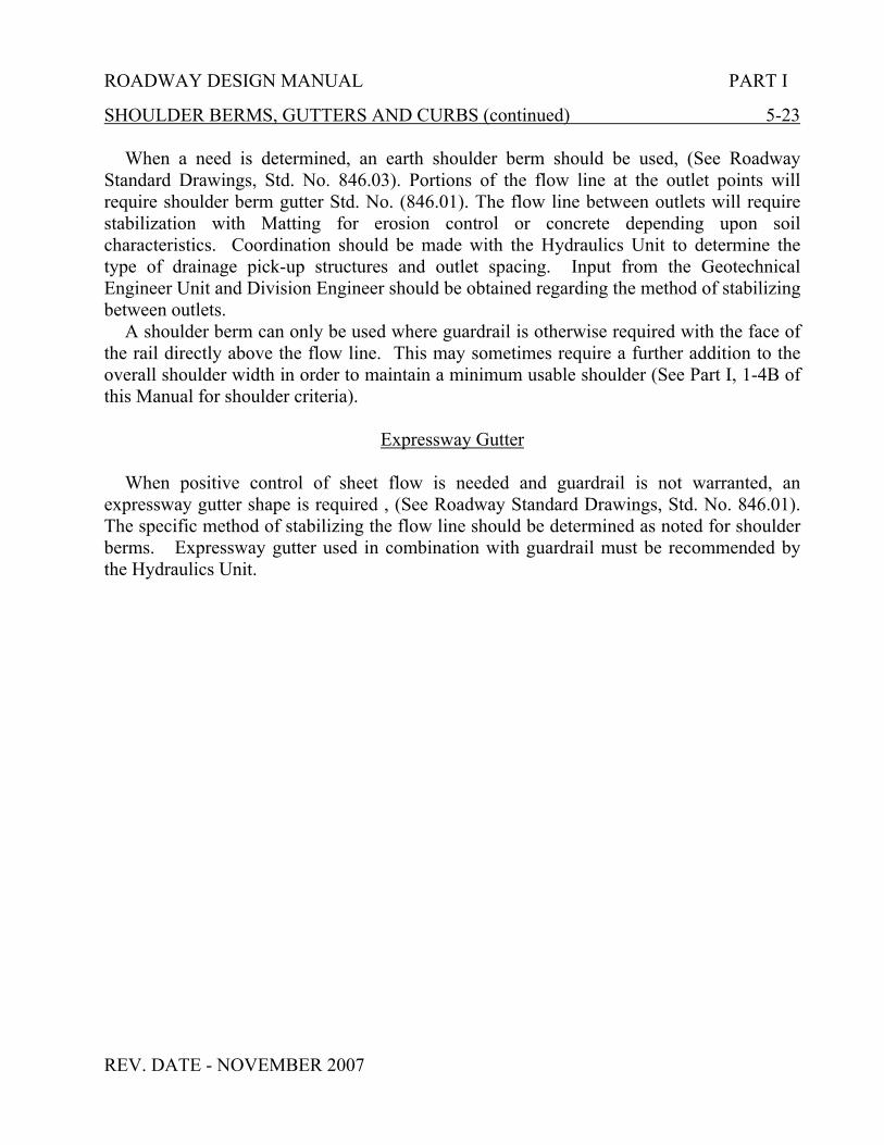
ROADWAY DESIGN MANUAL PART I
REV. DATE - NOVEMBER 2007
SHOULDER BERMS, GUTTERS AND CURBS (continued) 5-23
When a need is determined, an earth shoulder berm should be used, (See RoadwayStandard Drawings, Std. No. 846.03). Portions of the flow line at the outlet points willrequire shoulder berm gutter Std. No. (846.01). The flow line between outlets will requirestabilization with Matting for erosion control or concrete depending upon soilcharacteristics. Coordination should be made with the Hydraulics Unit to determine thetype of drainage pick-up structures and outlet spacing. Input from the GeotechnicalEngineer Unit and Division Engineer should be obtained regarding the method of stabilizingbetween outlets.
A shoulder berm can only be used where guardrail is otherwise required with the face ofthe rail directly above the flow line. This may sometimes require a further addition to theoverall shoulder width in order to maintain a minimum usable shoulder (See Part I, 1-4B ofthis Manual for shoulder criteria).
Expressway Gutter
When positive control of sheet flow is needed and guardrail is not warranted, anexpressway gutter shape is required , (See Roadway Standard Drawings, Std. No. 846.01).The specific method of stabilizing the flow line should be determined as noted for shoulderberms. Expressway gutter used in combination with guardrail must be recommended bythe Hydraulics Unit.

ROADWAY DESIGN MANUAL PART I
REV. DATE : NOVEMBER 2007
CHAPTER SEVEN
RAILROADS
SIGHT DISTANCES AT RAILROADS FOR UNSIGNALIZED CROSSING 7-1
The sight distance at railroad crossings is of utmost importance. When the exposureindex does not merit grade separations or railroad signals, use A Policy on GeometricDesign of Highways and Streets (2001), Exhibit 9-103, to provide safe stopping sightdistances. If physical barriers exist and it is not economically feasible to provide therequired distances, it shall be discussed with the Assistant State Roadway Design Engineer.
NOTE: Exhibit 9-103 is based on conditions of a 65′ truck crossing a single set of tracks at90˚. This allows for a margin of safety for conditions using other design vehicles.If it is determined by the designer that a small number of trucks will be using thefacility, consideration may be given to reducing the sight distance.
For Additional Information See:
A. Roadway Standard Drawings, Std. No. 1205.11 - Pavement Markings forRailroad Crossings
B. Chapter 18 of The Policy and Procedure Manual. C. Railroad-Highway Grade Crossing Handbook “Report No. FHWA - TS - 86 -
215, September, 1986” D. A POLICY ON GEOMETRIC DESIGN OF HIGHWAYS AND STREETS
(2001), Ch 9.
E. For Federal Highway-Rail Grade Crossing Relevant web links, go to: “http://safety.fhwa.dot.gov/fourthlevel/prof_res_hiwaygreadexing_links.htm”.
F. Railroad – Highway Grade CrossingSee “A POLICY ON GEOMETRIC DESIGN OF HIGHWAYS ANDSTREETS ” (2004), EXHIBIT 9-102.

ROADWAY DESIGN MANUAL PART I
REV. DATE : NOVEMBER 2007
SIGHT DISTANCES AT RAILROADS FOR UNSIGNALIZED CROSSING (Continued) 7-1
G. Moving Vehicle to Safely Cross or Stop at Railroad CrossingSee “A POLICY ON GEOMETRIC DESIGN OF HIGHWAYS ANDSTREETS ” (2004), EXHIBIT 9-103.
H. Required Design Sight Distance for Combination of Highway and TrainVehicle Speeds; 65′ Truck Crossing a Single Set of Tracks at 90˚.
See “A POLICY ON GEOMETRIC DESIGN OF HIGHWAYS ANDSTREETS ” (2004), EXHIBIT 9-104.
I. Departure of Vehicle from Stopped Position to Cross Single RailroadTrack.See “A POLICY ON GEOMETRIC DESIGN OF HIGHWAYS ANDSTREETS ” (2004), EXHIBIT 9-105.
TRACK CLEARANCE REQUIREMENTS ON CURB AND GUTTERPROJECTS PERPENDICULAR TO A RAILROAD 7-2
When curb and gutter is being constructed on a project that crosses a railroad, the curband gutter should be terminated 13′-6′′ from the centerline of the nearest rail of the tracks.The distance is measured perpendicular from the centerline of the rail to the face of curb. Inswitching areas where obstructions would be a hazard to trainmen, more than 13′-6′′ may berequired. The termination of the curb and gutter shall be discussed on the field inspectionand with the railroad companies if unusual conditions exist.
TRACK CLEARANCE REQUIREMENTS ON CURB AND GUTTERPROJECTS PARALLEL TO A RAILROAD 7-3
When it is necessary to construct curb and gutter parallel and in close proximity to arailroad, the location of the curb and gutter in relation to the nearest rail should be discussedwith the Utility Agent in the Right of Way Branch.

8 - 7
T - 1
VE
RT
IC
AL
SIG
HT
DIS
TA
NC
E C
ON
TR
OL
FO
R C
RE
ST
CU
RV
ES
AT
DIA
MO
ND
IN
TE
RC
HA
NG
ES
, S
IN
GL
E U
NIT
VE
HIC
LE
CR
IT
ER
IA
"K
" R
EQ
’D. T
O P
RO
VID
E
SIG
HT
DIS
TA
NC
E "
d"
FO
R S
U R
AM
P V
EH
ICL
E
SIG
HT
ING
OV
ER
BR
IDG
E
RA
IL4
"K
" R
EQ
’D. T
O P
RO
VID
E
SIG
HT
DIS
TA
NC
E "
d"
LE
FT
TU
RN
MA
NE
UV
ER
FO
R S
U R
AM
P V
EH
ICL
E
3
"K
" R
EQ
’D. F
OR
ST
OP
PIN
G
SIG
HT
DIS
TA
NC
E A
LO
NG
CR
OS
SR
OA
D2
SIG
HT
DIS
TA
NC
E "
d"
RE
Q’D
. F
OR
SU
RA
MP
VE
HIC
LE
, L
EF
T T
UR
NM
AN
EU
VE
R1
CR
OS
SR
OA
D
DE
SIG
N
SP
EE
D
70 M
PH
60 M
PH
50 M
PH
40 M
PH
10
60
FT
.
91
0 F
T.
76
0 F
T.
61
0 F
T.
23
5
17
3
12
1
78
*
* *
442
32
6
227
147
DE
NO
TE
S M
INIM
UM
"K
" T
O B
E U
SE
D F
OR
EA
CH
DE
SIG
N S
PE
ED
VE
RT
ICA
L S
IGH
T D
IST
AN
CE
SO
UL
D B
E P
RO
VID
ED
IN
CO
MB
INA
TIO
N W
ITH
HO
RIZ
ON
TA
L S
IGH
T
CO
NT
RO
LS
. T
HE
DE
SIG
N D
AT
A L
IST
ED
AB
OV
E I
S B
AS
ED
ON
UT
ILIZ
ING
TH
E S
U V
EH
ICL
E
AS
TH
E R
AM
P V
EH
ICL
E. W
ITH
A P
AS
SE
NG
ER
CA
R A
S T
HE
RA
MP
VE
HIC
LE
, T
HE
SIG
HT
DIS
TA
NC
E
PR
OV
IDE
D W
ITH
TH
E D
ES
IGN
DA
TA
LIS
TE
D A
BO
VE
AL
LO
WS
FO
R A
PP
RO
AC
H S
PE
ED
S G
RE
AT
ER
TH
AN
TH
E C
RO
SS
RO
AD
DE
SIG
N.
WIT
H A
WB
-50
, T
HE
AV
AIL
AB
LE
SIG
HT
DIS
TA
NC
E A
LL
OW
S
FO
R A
PP
RO
AC
H S
PE
ED
S O
F A
BO
UT
75%
OF
TH
E C
RO
SS
RO
AD
DE
SIG
N S
PE
ED
WH
ICH
IS
NO
TE
S:
1. S
IGH
T D
IST
AN
CE
"d" I
S E
ST
AB
LIS
HE
D B
Y A
AS
HT
O C
RIT
ER
IA F
OR
TH
E S
U C
ON
DIT
ION
;
2.
MIN
IMU
M "
K" F
OR
ST
OP
PIN
G S
IGH
T D
IST
AN
CE
AL
ON
G C
RO
SS
RO
AD
AC
CO
RD
ING
TO
TH
E
2
00
1 A
AS
HT
O C
RIT
ER
IA
3. D
ER
IVE
D F
RO
M K
=
d2
10
0 (
2h
I2
h2
)
WIT
H h
=
8.0
’, h =
4.2
5’
I2
4. R
AM
P V
EH
ICL
E D
RIV
ER
SIG
HT
S O
VE
R B
RID
GE
RA
IL (
2.6
7’
RA
IL H
T.)
. R
AIL
DO
ES
NO
T
O
BS
TR
UC
T H
OR
IZO
NT
AL
OR
VE
RT
ICA
L S
IGH
T L
INE
S F
OR
RE
QU
IRE
D "
d";
h =
(8.O
’ -
2.6
7’) h =
(4.2
5’ -
2.6
7’)
I2
AP
PR
OX
IMA
TE
LY
TH
E A
VE
RA
GE
RU
NN
ING
SP
EE
D O
F T
HE
CR
OS
SR
OA
D T
RA
FF
IC.
SIG
HT
DIS
TA
NC
E O
BT
AIN
ED
BY
SIG
HT
ING
IN
SID
E B
RID
GE
RA
IL.
VE
RT
ICA
L S
IGH
T D
IST
AN
CE
EL
EM
EN
TS
SU
VE
HIC
LE
"d
" =
SIG
HT
DIS
TA
NC
E F
OR
LE
FT
TU
RN
MA
NE
UV
ER
"d
"
L =
LE
NG
TH
OF
VE
RT
ICA
L C
UR
VE
G1
G2
K =
L/A
h2=
4.2
5’
h1=
8’ S
U
*
2
A =
AL
GE
BR
AIC
DIF
F. IN
GR
AD
ES
(G
2 -
G1)
TABLE 1
*
247
15
1
84
44
, A
PO
LIC
Y O
N G
EO
ME
TR
IC
DE
SIG
N O
F H
IG
HW
AY
S A
ND
ST
RE
ET
S (
2004)
REV. DATE: NOVEMBER 2007

ROADWAY DESIGN MANUAL PART 1
REV. DATE : 01/02/02

ROADWAY DESIGN MANUAL PART 1
REV. DATE: NOVEMBER 2007
CHAPTER TEN
ENTRANCES
DESIGN OF COMMERCIAL ENTRANCES 10-1
A paved driveway turnout (Std. No. 848.04) shall be used for commercial type entrancesthat generate 500 ADT or more. A shopping center is considered a major traffic generator.To provide the most efficient ingress and egress movements, minimum 25′ radii should beprovided. Longer radii should be considered to better accommodate service type vehicles.The designer is also encouraged to provide as much channelization as possible into anycommercial development that is being constructed in conjunction with a roadway project.
For commercial type developments that generate less than 500 ADT, a paved drivewayturnout (Std. No. 848.02 or Std. No. 848.03) may be used. A small family business isconsidered a minor traffic generator.
For additional information, see the "Policy on Street and Driveway Access to NorthCarolina Highways" from the Alternative Delivery Unit or on the NCDOT website:
http://www.ncdot.org/doh/preconstruct/altern/value/manuals/
DESIGN OF PRIVATE ENTRANCES 10-2
A minimum 20′ width should be used for standard driveway turnouts in conjunction withcurb and gutter (Std. No. 848.02 or Std. No. 848.03). A 16′ width driveway turnout may beused where justified and approved by the Engineer.
ENTRANCE PIPES 10-3
On minimum type driveways, the total graded width should not be less than 16′. Thisallows for an effective paved or aggregate travelway of 12′. Normally, 20′ of 15″ pipewould be required for a drive of this type having minimum cover. However, soundengineering judgment should be used in determining the proper driveway width and lengthof pipe based upon factors such as skew of drive, height of cover, type of drive, and unusualtraffic patterns. On drives where commercial vehicles are subject to encroach upon the endof pipe, extension of the pipe may be justified.
When a clear roadside recovery area is being provided on a project, the ditches shall begraded to allow installation of the entrance pipes at the same specified distances. See Part I,Chapter 5-20, of this Manual for additional information.

ROADWAY DESIGN MANUAL PART 1
REV. DATE 01/02/02
DISCUSSION OF ENTRANCES ON FIELD INSPECTIONS 10-4
Standard street and driveway turnouts shall always be discussed during the FieldInspections. The type and location shall be approved by the field inspection review team.This information is included in the “notes for field inspection”.
There is information available in the Manuals Group, Special Services Section of theAlternative Delivery Unit, for the designer's use in the design of parking lots.
There is also information available on the channelization of intersections and commercialestablishments.
REPLACEMENT OF EXISTING DRIVEWAYS 10-5
When widening an existing roadway, the Project Engineer shall assure that all existingaccess connections that are to be replaced conform to the current edition of the “Policy onStreet and Driveway Access to North Carolina Highways”. No new drivewayturnouts/connections shall be placed/altered on the final plans without the express consentand approval of the local District Engineer. When it is determined that a new accessconnection will be allowed, a separate agreement between the Department of Transportationand the applicant will be required.

ROADWAY DESIGN MANUAL PART 1
REV. DATE: NOVEMBER 2007
CHAPTER ELEVEN
COMPUTATIONS
QUANTITY CALCULATIONS
The Calculation of Quantities Worksheets, for most of the major pay items encounteredin finalizing projects, can be found on the computer website: “http://www.ncdot.org/doh/preconstruct/ps/contracts/standards/quantities/default.html”.
These work sheets contain information (formulas, sketches, etc.) to explain the Method ofCalculating Quantities. Additional information is available in this chapter and can bediscussed with the Plan Review Engineer.
ROADWAY ITEM (PAVEMENT) 11-1
PROOF ROLLING 11-1A
Proof rolling is recommended by the Geotechnical Engineering Unit. When thepavement design recommendations are submitted to the Project Engineer, proof rollingrecommendations will be included. The recommendations shall also be discussed on thefield inspection.
Proof rolling is to be performed to a width of 2ʹ (feet) outside the proposed top edges offull depth pavement. Proof rolling is computed at the rate of three hours per 24ʹ width offull depth pavement per mile. Full depth pavement widths other than 24ʹ shall be proratedto correspond with this unit measurement. Final payment will be in accordance withSection 260 of the "Standard Specifications for Roads and Structures".
Example Methods Of Computing Hours Per Mile Of Proof Rolling For Various WidthPavements.:
Example 1. 22ʹ Width Roadway, With No Paved Shoulders.22ʹ ( two 11ʹ Lanes ) + 4ʹ ( 2ʹ outside lt. & rt. Full Depth Pavement ) = 26ʹ width.26ʹ width x ( 3 hrs. per mile\ per 24ʹ roadway width ) = 3.25 hrs. per mile.
Example 2. 24ʹ Width Roadway, With 2ʹ Full Depth Paved Shoulders.24ʹ ( two 12ʹ Lanes ) + 4ʹ ( 2ʹ Full Depth Paved Shoulders lt. & rt. ) + 4ʹ ( 2ʹ outsidelt. & rt. Full Depth Pavement ) = 32ʹ width.32ʹ width x ( 3 hrs. per mile\ per 24ʹ roadway width ) = 4.00 hrs. per mile.
Example 3. 60ʹ Width Roadway, With 4ʹ Full Depth Paved Shoulders.60ʹ ( five 12ʹ Lanes ) + 8ʹ ( 4ʹ Full Depth Paved Shoulders lt. & rt. ) + 4ʹ ( 2ʹ outside
Full Depth Pavement lt. & rt. ) = 72ʹ width.72ʹ width x ( 3 hrs. per mile\ per 24ʹ roadway width ) = 9.00 hrs. per mile.

ROADWAY DESIGN MANUAL PART 1
REV. DATE 04/01/03
AGGREGATE BASE COURSE (ABC) 11-1B
When all calculations are completed and totaled, the following procedures shall be usedin the computation of ABC quantities.
0 TO 1000 TONS OF ABC – ADD 10% 1001 TO 5000 TONS OF ABC – ADD 5% 5001 TONS OF ABC AND ABOVE – ROUND OFF TO NEXT 100 TONS
PRIME COAT 11-1C
Section 600 of the Standard Specifications For Roads and Structures states that primecoat will not be required unless called for on the plans and in the estimate.
Areas where prime coat should be included on a project are as follows:
1. On mainline and/or -Y- line paving areas when requested by Division Engineer,if approved by the Pavement Management Unit.
2. On any paving project (including detours and paved shoulders) when thebituminous concrete thickness is less than 2″.
3. In conjunction with 10′ paved shoulders, if the remainder of the shoulder is all ABC, this area should be primed at a rate of 0.5 gallons per Sq. Yd.
Areas to be primed are shown on the typical sections.
SUBGRADE STABILIZATION 11-1D
When stabilized Subgrade is specified in the Geotechnical Recommendations forPavement Design, it shall be included in the Pavement Schedule and shall be shown on theapplicable typical sections.(See Pavement Schedule in this manual, Part II, 6-lD, F-1.) Thefollowing widths shall be used for stabilization:
(1) Width in curb and gutter sections - Edge of pavement to edge of pavement.(2) Width in shoulder sections - One foot outside the top edges of the full depth
pavement structure. (Include full depth paved shoulders.)(3) Do not use stabilization on pavement widths less than six feet.
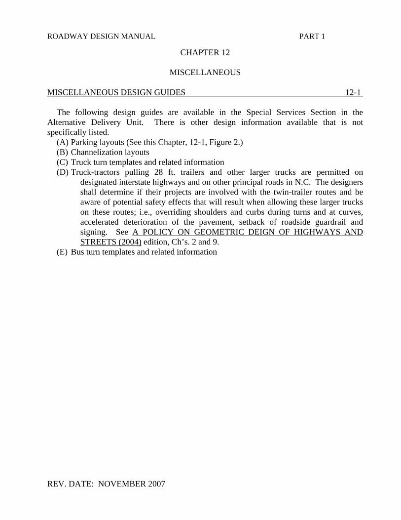
ROADWAY DESIGN MANUAL PART 1
REV. DATE: NOVEMBER 2007
CHAPTER 12
MISCELLANEOUS MISCELLANEOUS DESIGN GUIDES 12-1 The following design guides are available in the Special Services Section in the Alternative Delivery Unit. There is other design information available that is not specifically listed. (A) Parking layouts (See this Chapter, 12-1, Figure 2.) (B) Channelization layouts (C) Truck turn templates and related information (D) Truck-tractors pulling 28 ft. trailers and other larger trucks are permitted on
designated interstate highways and on other principal roads in N.C. The designers shall determine if their projects are involved with the twin-trailer routes and be aware of potential safety effects that will result when allowing these larger trucks on these routes; i.e., overriding shoulders and curbs during turns and at curves, accelerated deterioration of the pavement, setback of roadside guardrail and signing. See A POLICY ON GEOMETRIC DEIGN OF HIGHWAYS AND STREETS (2004) edition, Ch’s. 2 and 9.
(E) Bus turn templates and related information


ROADWAY DESIGN MANUAL
ROADWAY DESIGN UNIT
UTILIZATION OF DESIGN MANUAL AND MANUAL FORMAT
PART TWO
Part two of this manual is primarily directed to the actual preparation of the plans. Mostof the information is provided in narrative form. Illustrations are provided for some of theinformation, which should become standardized in all roadway plans. However, to provide theProject Engineer, Section Engineer and the designer with some flexibility in plan preparation andstill maintain reasonable conformity in the finalization of plans, specifications and estimates;rigid guidelines such as "sample plans" or "plan illustrations" are not provided.
This manual provides design criteria in charts, tables and illustrations. When theinformation is in one of these forms, usually an explanation does not accompany them except fornotes to cover varying conditions. Because all of the design concepts presented can not becompletely covered, references to additional literature is given at the bottom of the chart. TheReference or Guide Manual denoted will be accompanied by a page number. The page numbersare for "quick" reference when more background information is necessary. Reference to thesemanuals will alleviate the repeating of detailed information in the reference books.
Design information is also included in narrative form. Any design criteria not included inthis manual in narrative or chart form will be in the Roadway Policy and Procedure Manual orreferences made to other publications listed in Part Two, Chapter 24 of this manual. Noreference will be made to design practices believed to be common knowledge by the wellinformed and experienced design staff of the Department of Transportation.
REV. DATE: NOVEMBER 2007


ROADWAY DESIGN MANUAL PART II
REV. DATE NOVEMBER 2007
CHAPTER THREE
TITLE SHEET
PURPOSE 3-1
The Title Sheet provides information related to location of project, length of project,and type of work. Specific information to be shown on the title sheet is included belowand in the Checklist:
http://www.ncdot.org/doh/preconstruct/ps/specifications/specifications_provisions.html
LOCATION OF PROJECT AND TYPE OF WORK 3-lA
The location of project and type of work is used repeatedly on various engineeringdocuments throughout the duration of a project. Since the space available on variousproject documents for writing this information is usually limited, the descriptions for thelocation and type of work shall be kept to an absolute minimum. In describing thelocation, the information shall be limited to the county or counties, route, and thebeginning and ending points. In listing the type of work, it shall be limited to the majortypes of construction.
PROJECT LAYOUT 3-lB
The project layout is a small scale drawing of each plan sheet. The sheet number isshown on each superimposed plan sheet on the layout. This provides a quick reference to aspecific location in the plans. The layout should include all interchanges, intersections,service roads, structures, railroads, outstanding geographical features, and any other majorlandmarks that may be used as reference points.
VICINITY MAP 3-lC
A vicinity map is required to show sufficient identifying information so that the projectmay be easily located on a county or state map. The vicinity map may be a tracing of anytype map that will provide the most beneficial information. The beginning and endingpoints of the project should always be shown on the vicinity map. Major transportationfacilities convenient for transporting construction materials to the project site should alsobe shown.
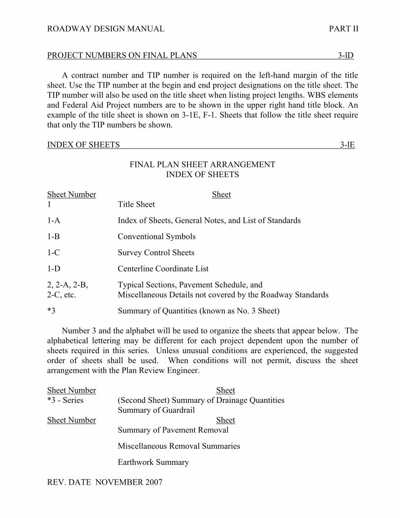
ROADWAY DESIGN MANUAL PART II
REV. DATE NOVEMBER 2007
PROJECT NUMBERS ON FINAL PLANS 3-lD
A contract number and TIP number is required on the left-hand margin of the titlesheet. Use the TIP number at the begin and end project designations on the title sheet. TheTIP number will also be used on the title sheet when listing project lengths. WBS elementsand Federal Aid Project numbers are to be shown in the upper right hand title block. Anexample of the title sheet is shown on 3-1E, F-1. Sheets that follow the title sheet requirethat only the TIP numbers be shown.
INDEX OF SHEETS 3-lE
FINAL PLAN SHEET ARRANGEMENTINDEX OF SHEETS
Sheet Number Sheet1 Title Sheet
1-A Index of Sheets, General Notes, and List of Standards
1-B Conventional Symbols
1-C Survey Control Sheets
1-D Centerline Coordinate List
2, 2-A, 2-B, Typical Sections, Pavement Schedule, and2-C, etc. Miscellaneous Details not covered by the Roadway Standards
*3 Summary of Quantities (known as No. 3 Sheet)
Number 3 and the alphabet will be used to organize the sheets that appear below. Thealphabetical lettering may be different for each project dependent upon the number ofsheets required in this series. Unless unusual conditions are experienced, the suggestedorder of sheets shall be used. When conditions will not permit, discuss the sheetarrangement with the Plan Review Engineer.
Sheet Number Sheet*3 - Series (Second Sheet) Summary of Drainage Quantities
Summary of GuardrailSheet Number Sheet Summary of Pavement Removal
Miscellaneous Removal Summaries
Earthwork Summary

ROADWAY DESIGN MANUAL PART II
REV. DATE NOVEMBER 2007
CHAPTER FOUR
GENERAL NOTES
PURPOSE 4-1
General notes are provided to help clarify the plans. The most frequently usedgeneral notes appear on the website at:
http://www.ncdot.org/doh/preconstruct/ps/contracts/standards/checklists/1A.html
It is the responsibility of the Project Engineer or Project Design Engineer to denote thegeneral notes pertinent to his project and to write additional notes which do not appear on thewebsite. Only general notes relative to project should be shown.


ROADWAY DESIGN MANUAL PART II
REV. DATE NOVEMBER 2007
CHAPTER FIVE
ROADWAY STANDARDS, SPECIAL PROVISIONS AND CONTRACTS
PURPOSE AND LOCATION OF ROADWAY STANDARDS 5-1
A list of the roadway standards that are applicable to each project is to be listed inthe plans. Usually, these standards are listed on Sheet 1-A of the plans. An up-to-date listof the standards is available on Project Services WebPages.
For additional information related to roadway standards, refer to the currentRoadway Standard Drawings Manual.
NOTE: For up-to-date listing of Roadway Standard Drawings, Please, see ourWebPages at
http://www.ncdot.org/doh/preconstruct/ps/std_draw/.
PROPOSAL LINE UP 5-1A
A list of information that is required for inclusion into bidding proposals is availableon our WebPages at:
http://www.ncdot.org/doh/preconstruct/ps/contracts/expedi/default1.html.
It is the responsibility of the Project Engineer to prepare a checklist for the applicableproject special provisions and standard special provisions for each project. It shall be theresponsibility of the State Contract Officer to review the checklist prior to the finalassembly of the proposal form.The following lists are available:(1) Proposal line up(2) General construction projects(3) Resurfacing projects
PLANT PEST QUARANTINES 5-2
The Roadway Design Unit is responsible for assisting the Division Engineer inmaintaining compliance with the federal and state plant pest quarantines. A list of countieswith plant pest quarantines is provided in this guideline (5-2A).
It is the responsibility of the Project Engineer to determine if a project is in aquarantine area. This shall always be discussed on the field inspection. When a project isin a quarantine area, a special provision will be required in the contract.

ROADWAY DESIGN MANUAL PART II
REV. DATE 02/08/02
LIST OF COUNTIES WITH PLANT PEST QUARANTINES 5-2A
COUNTY IMP. FIRE ANT WITCHWEED OTHER NOXIOUSWEEDS*
Anson XAshe XAvery XBeaufort XBladen X X XBrunswick X XBuncombe XCarteret XChatham XCleveland XColumbus X X XCraven X XCumberland X X XDare XDuplin X XDurham XForsyth XGaston XGranville XGreene XHalifax XHarnett XHaywood XHenderson XHoke X XHyde X XJackson XJohnston XJones XLenoir X XLincoln XMadison X
*NOTE: The movement of class A or B noxious weeds or any regulated article infestedwith class A or B noxious weeds into North Carolina is prohibited. The movement of classA noxious weed or any regulated article infested with any class A noxious weed or anyregulated article infested with any class A noxious weed is prohibited throughout the state.For further information on other noxious weeds, refer to Title 2, Chapter 43, Subchapter A,Sections .1701- .1708 of the North Carolina Administrative Code. Copies of the regulationsfor state noxious weeds are available by contacting the N.C. Department of Agriculture,P.O. Box 27647, Raleigh, NC 27611, (919-733-6930).

ROADWAY DESIGN MANUAL PART II
REV. DATE 02/08/02
LIST OF COUNTIES WITH PLANT PEST QUARANTINES (continued) 5-2A
Martin XMecklenburg XMitchell XMontgomery XNew Hanover X XNorthampton XOnslow X XOrange XPamlico XPender X XPerquimans XPitt X XRandolph XRichmond XRobeson X XRowan XRutherford XSampson X XScotland XTyrrell X XUnion XWake XWarren XWashington XWatauga XWayne XYancey X
*NOTE: The movement of class A or B noxiuos weeds or any regulated article infestedwith class A or B noxiuos weeds into North Carolina is prohibited. The movement of classA noxious weed or any regulated article infested with any class A noxious weed isprohibited throughout the state. For further information on other noxious weeds, refer toTitle 2, Chapter 43, Subchapter A, Sections .1701- .1708 of the North CarolinaAdministrative Code. Copies of the regulations for state noxious weeds are available bycontacting the N.C. Department of Agriculture, P.O. Box 27647, Raleigh, NC 27611, (919-733-6930).

ROADWAY DESIGN MANUAL PART II
REV. DATE NOVEMBER 2007
RARE AND ENDANGERED PLANT SPECIES 5-3
The Project Development and Environmental Analysis Branch is responsible forconducting research to determine the probability of rare and endangered plant species whichmay be encountered on proposed highway projects. However, when research and on-siteinvestigations are being conducted by the Project Engineer and it is determined thatsensitive plants are being disturbed, it shall be discussed with the Roadside EnvironmentalUnit.
When a plant species is being disturbed, a special provision will be required in thecontract. See the Contracts Section in the Project Services Unit.

ROADWAY DESIGN MANUAL PART II
REV. DATE NOVEMBER 2007
CHAPTER SIX
TYPICAL SECTIONS
PURPOSE 6-1
A typical section is a cross-sectional representation of a proposed roadway showinggrading and paving details. Typical sections shall include all elements necessary to constructthe roadbed and/or pavement structure.
NUMBER OF TYPICAL SECTIONS 6-1A
Typical sections shall be drawn for each different pavement design and for majorvariations in component widths. Partial typical sections and notes should be used for minorvariations; thereby minimizing the number of typical sections required.
Typical sections or part sections are not needed for auxiliary lanes or tapers (planscover this)
Typical sections are not needed to cover super-elevations unless there are no normalcrown conditions on the segment of roadway for which the typical section applies.(Roadway standard drawings 560.01 and 560.02 show this method of constructions).
DIMENSIONS 6-lB
Dimensions shall be shown for all typical section elements. Horizontaldimensions shall be shown in feet and inches to the nearest inch. Dimensions shall belimited to those required to clearly explain the intent of the typical section.
LIMITS OF USE 6-1C
Each typical section shall include a listing of the locations where it applies. Theselocations shall be designated by survey line and station to station limits. Station to stationlimits shall be broken at beginning and ending of bridges (not approach slabs). Stations shallalso be broken for Equalities, if applicable.
PAVEMENT SCHEDULE 6-1D
A full pavement schedule shall be shown on the first typical section sheet and shallcontain a code and a description for all elements of the various pavement designs applicableto the project. The engineer shall show an abbreviated pavement schedule on the remainingTypical Section Sheets for easy reference. The following code letters shall be used:

ROADWAY DESIGN MANUAL PART II
REV. DATE 02/08/02
PAVEMENT SCHEDULE (continued) 6-1D
CODE LETTER ITEM
A Portland Cement Concrete Pavement
B Open-Graded Asphalt Friction Course, Type FC
C Asphalt Concrete Surface Course, Type S
D Asphalt Concrete Intermediate Course, Type I
E Asphalt Concrete Base Course, Type B
F Asphalt Surface Treatment
G Cement Treated Base Course
J Aggregate Base Course
K Soil-Cement Base
Lime-Treated Soil
L Stabilizer Aggregate
M Soil Type Base Course
P Prime Coat
R Combination Concrete Curb and Gutter
Concrete Curb
5″ Monolithic Concrete Island
Concrete Island Cover
S Concrete Sidewalk
T Earth Material
U Existing Pavement
V As needed
W Variable Depth Asphalt Pavement (See Standard Wedging Detail).
X Permeable Asphalt Drainage Course, Type P
Y Z As needed

ROADWAY DESIGN MANUAL PART II
REV. DATE NOVEMBER 2007
CHAPTER SEVEN
SPECIAL DETAILS
PURPOSE 7-1
Construction details that are not included in the Roadway Standard Drawings have tobe detailed in the plans. The squad responsible for the Final Construction Plans preparesdetails for BENCHING EXCAVATION FOR EMBANKMENT, UNDERCUTEXCAVATION, and FALSE CUTS.
Before special construction details are drawn for a project, the Project Engineer shallcheck with the Standards Engineer. He has copies of special drawings that have been usedon previous projects. Usually, these details can be adapted to fit most projects.
The Standards Engineer will also be familiar with any general notes, specialprovisions, or references that need to be made to the Special Construction Details.
BENCHING EXCAVATION FOR EMBANKMENT 7-2
Benching excavation is to be shown on the plans in accordance with the Soils andFoundation Section. The locations to be benched shall be discussed on the preliminary fieldinspection. If the field inspection party is not agreeable to the locations shown on the plans,the Project Engineer shall discuss the locations with the Geotechnical Engineer. If there areany revisions to be made, they shall be made on the final plans and discussed on the finalfield inspection.
For additional information related to benching, see Section 235 of the StandardSpecifications for Roads and Structures.
UNDERCUT EXCAVATION 7-3
A Special Detail shall be shown in the plans to show the limits of undercutexcavation. The area to be undercut shall also be shown on the profile sheets and cross-sections.
When subsurface plans are provided by the Geotechnical Engineering Unit, theproposed undercut excavation shown on the plans shall not deviate from theirrecommendations.
When subsurface plans are not available, a general note shall be included in the plansstating that no subsurface plans are available.
The limits of undercut varies, dependent upon the location and project conditions.

ROADWAY DESIGN MANUAL PART II
REV. DATE NOVEMBER 2007
FALSE CUTS 7-4
False cuts are designed to eliminate or reduce hazards and may sometimes be usedfor noise abatement. Utilization of false cut must be based on a project by project basiswith strong consideration given to economics, aesthetics, safety and engineering judgment.
See 7-4, Figure F-1 & F-2 for examples of false cuts.
LOCATION
The use of false cuts should be discussed and locations determined at the Final DesignInspection.

ROADWAY DESIGN MANUAL PART II
REV. DATE NOVEMBER 2007

ROADWAY DESIGN MANUAL PART II
REV. DATE NOVEMBER 2007

ROADWAY DESIGN MANUAL PART II
REV. DATE NOVEMBER 2007
CHAPTER TEN
FENCING
FENCING OF FULL CONTROL & PARTIAL CONTROL OF ACCESS 10-1
All full control and partial control of access projects will be fenced along the rightof way or in the outer separation when frontage roads are present, unless the terrainprohibits access to the roadway by either vehicles or pedestrians by natural means. Eachproject shall be studied individually to determine if the fence can be eliminated at suchthings as rivers, streams, deep cuts or high fills. Questionable areas should be discussed atthe Final Design Inspection and recommendations included in the Field Inspection Reportfrom the Division Engineer. See Policy and Procedure Manual, 19/3.
FENCING OF REST AREAS & WELCOME CENTERS 10-2
The type fence to be used at each rest area or welcome center shall be determinedon an individual basis through coordination with the Roadside Environmental Unit.
FENCING OF TRUCK WEIGH STATIONS 10-3
The type fence to be used at each truck weigh station will be determined on anindividual basis through coordination with the Special Design Section Engineer of theRoadway Design Unit.
FENCING IN PROXIMITY TO AIRPORTS 10-4
Fencing in proximity to airports shall be discussed with the Federal AviationAdministration to determine if nonmetallic fencing should be used. Contact can be madethrough the DOT Director of Aviation.
FENCE LOCATIONS AT RIVERS AND STREAMS 10-5
The proposed method of fencing at streams shall be detailed in the plans anddiscussed at the field inspection. At stream crossings, the fence should be installed underthe structure. The fence should be tied into the wingwall at box culverts.

ROADWAY DESIGN MANUAL PART II
REV. DATE NOEMBER 2007
FENCE LOCATIONS AT 54″ PIPES AND ABOVE 10-6
At pipes 54″ and above, the fence should be tied into the end walls.FENCE LOCATIONS AT OVERPASSES 10-7
Fencing at overpasses shall be installed in accordance with one of the suggestedtreatments shown in Figure 1 and 2. In locations where the fence is tied into the bridge,extreme caution shall be taken to assure that sight distances are not obstructed.
TYPES OF FENCE 10-8
Either woven wire or chain link fence may be used for establishing control ofaccess. Unusual conditions may justify the use of a special type fence, which must beapproved by the State Roadway Design Engineer and FWHA if applicable.
The type of fence to be used shall be discussed at the Final Design Field Inspectionand recommendations included in the Field Inspection Report from the Division Engineer.If there are differences of opinion, they shall be resolved prior to distribution of the right ofway plans.
(A) WOVEN WIRE FENCE
Woven wire fence shall be used except where there is a specific need for chain linkfence or a special type of fence. When chain link or a special type fence is beingconsidered, actual land usage at the time the project is in the design stage should be thedetermining factor, unless a change in land use is imminent. This decision should not bebased on blanket categories such as anticipated development, zoning classifications, insideor outside city limits or rural-urban classifications.
See Roadway Standard Drawings, Std. No. 866.02 and 866.03
(B) CHAIN LINK FENCE
Chain link fence shall be used in the following areas:
(1) A residential area where the average size of those lots adjacent to the right of waydoes not exceed one (1) acre.
(2) Any area where medium to heavy pedestrian activity will routinely occur closerthan 150 feet to the proposed fence location. All developed land should be studiedto determine if this type of activity is generated. Chain link fence shall not be usedin institutional, commercial, office, or industrial areas that do not generate suchactivity. The presence

ROADWAY DESIGN MANUAL PART II
REV. DATE NOEMBER 2007
TYPES OF FENCE (continued) 10-8 of buffer zones or park like areas adjacent to a developed area will often preclude the need for chain link fence. (3) Any area which the right of way agreement with the property owner requires that chain link fence be installed by the Department of Transportation. (4) Where short sections of woven wire fence would be required to comply with the policy. See Roadway Standard Drawings, Std. No. 866.01. (C) SPECIAL TYPE FENCE Special type fences will be considered on an individual basis and discussed during the preliminary field inspection or during right of way negotiations. Special fences include security fences, masonry walls and different types of fences used for screening, landscape purposes, or sound barriers. HEIGHT OF FENCING 10-9 Woven Wire Fence 47″ Fabric Chain Link Fence 48″ Fabric Where bikepaths are being separated from the roadway, a minimum 4.5-foot high fence is recommended. Exceptions to the above heights or inclusion of a top rail on chain link fence must be considered on a project by project basis. GATES 10-10 When it is necessary to gain access to utilities and drainage areas, locked gates shall be considered. Use of gates will be determined on a project by project basis, on Final Design Field Inspection and during right of way negotiations. After it has been determined that a gate is required, it will usually be stipulated in the right of way agreement, and shown on the Final Construction Plans. See Roadway Standard Drawings, Std. Nos. 866.01, 866.02 and 866.03

ROADWAY DESIGN MANUAL PART II
REV. DATE 02/08/02

ROADWAY DESIGN MANUAL PART II
REV. DATE 02/08/02
CHAPTER 12
TRAFFIC OPERATIONS
MAINTENANCE OF TRAFFIC DURING CONSTRUCTION 12-1
In the design of a project, the traffic control plan is an essential element indetermining a method for maintaining a safe flow of traffic through a construction zone,determining the need for on-site detours, or directing traffic to alternate routes. The trafficcontrol plans are a part of the final construction plans and are prepared by the TrafficControl Unit in coordination with the Roadway Project Design Engineer.
Maintenance of traffic should be considered during the functional and preliminarydesigns. A conceptual plan should be prepared for any detours, and should be made a partof the Combined or Design Public Hearing Map, especially if the detour will requireadditional right of way. On Categorical Exclusions for Bridge replacements projects, thedeterminations of either an on-site detour, or detouring traffic around the project byalternate routes, is an integral part of the document.
TRAFFIC OPERATIONS PLAN 12-2
The Roadway Project Design Engineer, in coordination with the Traffic ControlProject Engineer, shall prepare a Traffic Operations Plan. This plan should be used toconvey the design decisions that were determined necessary to provide constructability ofthe project, while safely maintaining traffic through the construction zone. It should beincluded with a set of plans submitted to the Traffic Control Unit at the same time plans aresubmitted to the Hydraulics Unit.
The Traffic Operations Plan should include the following:
1) A sketch map showing the overall project, along with roads and streetsplanned to be used for alternate routes during construction, or phases ofconstruction should be provided. Proposed off-site detours should be markedon the map and described with a note. (Maps similar to a county map wouldbe adequate for a sketch map.)

ROADWAY DESIGN MANUAL PART II
REV. DATE NOVEMBER 2007
TRAFFIC OPERATIONS PLAN (continued) 12-2
2) A layout map, similar to the plan sheet layout on the title sheet, should beused to show on-site detours, off-site detours, construction phasing and trafficpatterns through the construction zone. Notes describing the phasing or trafficshifts should be included on the layout map. On complicated projects, two ormore layout maps may be required for clarity of construction phasing.Controlling earthwork and undercutting operations must be carefullyconsidered to ensure constructability.
3) Using construction year traffic, a capacity analysis of all streets, roads andintersections that will be used for detours should be performed, and reviewedto determine if improvements will be required to handle additional traffic.
4) Show a typical section of any proposed new detour alignments or phasingareas.
5) Mark any streets that will be dead ended.
6) Show locations of existing signals and proposed temporary signals.
7) Identify culverts and bridges that will require staged construction.
8) Identify potential grade problems between existing and proposed.
The Work Zone Traffic Control Unit will further develop this Traffic OperationsPlan, coordinating with the Roadway Design Project Engineer, to prepare a ConstructionStaging Concept package to be incorporated into the Final Design Field Inspection plansand presented by the Work Zone Traffic Control Unit at the Final Design Field Inspectionmeeting. After initial discussions at the Final Design Field Inspection, The ConstructionStaging Concept should be removed from the plans.

ROADWAY DESIGN MANUAL PART II
REV. DATE NOVEMBER 2007
TRAFFIC CONTROL PLAN REVIEW MEETINGS 12-3
Approximately 4 to 6 weeks after the Final Design Field Inspection, a separatemeeting may be held, if needed, to discuss constructability and design problems related tothe maintenance of traffic. Attendees normally should include at least one member eachfrom Roadway Design and Work Zone Traffic Control, as well as the Resident Engineerand/or their Assistant, Division Construction Engineer, Area Roadway ConstructionEngineer and/or Area Bridge Construction Engineer, Division Traffic Engineer and others,as required. The Traffic Control Unit, notifying the appropriate personnel will coordinatethis meeting by form letter.
Similarly, another meeting to discuss details of traffic control may be held after thePre-Let Field Inspection, approximately three weeks prior to the date that the TrafficControl Plans are due to be turned in. At this time, the Work Zone Traffic Control Unit willpresent plans for review and discussion that incorporated any recommendations from thePre-Let Field Inspection meeting, and are approximately 90% to 100% complete for turn-in.
These traffic control plan review meetings are additional meetings to discuss thetraffic control in depth. They are not a replacement for the Final Design and Pre-Let FieldInspections. Traffic Control Plans should still be presented and discussed at these meetings.
DESIGN OF ON-SITE DETOURS AND MEDIAN CROSSOVERS 12-4
After the Final Design Field Inspection, the Roadway Project Design Engineer willcoordinate the location and design of on-site detours and median crossovers with the WorkZone Traffic Control Project Engineer. The design of on-site diversions and mediancrossovers (including horizontal and vertical alignments) will be the responsibility of theRoadway Design Unit, and will be a part of the roadway plans. The design of the crossoversor diversions may be shown on a separate plan sheet, and should be included in the roadwayplan. Similarly, typical sections for detours, median crossovers and temporary wideningshould also appear in the roadway plans.
Median crossovers or detours not requiring right of way can be included with thedetail sheets. Cross-reference notes will be required on both roadway plans and trafficcontrol plans.

ROADWAY DESIGN MANUAL PART II
REV. DATE 02/08/02
DESIGN OF ON-SITE DETOURS AND MEDIAN CROSSOVERS (continued) 12-4
Detour designs will be based on the functional classification of the roadway. THEFOLLOWING CRITERIA WILL BE THE MINIMUM ACCEPTABLE DESIGNSTANDARDS FOR EACH CLASSIFICATION:
INTERSTATE AND FREEWAYS:
The design speed (V) of horizontal and vertical curves for crossovers and diversionson interstates and freeways will be the same or greater than the posted speed limit. Theywill be designed so that there will not be a need for a reduction in the posted speed limit.
Exceptions:1) For short-term lane closures, design speed (V) does not have to be maintained
for cross-over designs. It is often desirable to slow down the traffic.
Detours and median cross-overs should also be designed without a reduction in thenumber of lanes of traffic.
Exceptions:1) Traffic Control phasing will sometimes allow short term lane closures
during daylight hours, but detours should be designed to maintain existingnumber of lanes during peak hours.
2) Certain Interstate and freeway routes may have low traffic volumes. TheTraffic Control Unit will determine on a case-by-case evaluation if long-term lane closures are permitted.
Superelevation for proposed horizontal alignments in median crossovers cannot meetdesign speed standards due to existing restraints. It is more desirable to have lowerSuperelevation rates, that smoothly transition vehicles through the alignment, thanhigher rates, with short lengths of change that create abrupt vehicle behavior. It is,however, critical that the surface of the proposed roadway be reviewed for areas thatdo not drain well. Hydroplaning during periods of rain can be created by long, levelsections of pavement, and also by concrete barrier placed along the edge of theroadway. Grade and superelevation changes or special drainage features shouldcorrect these problems. Shoulder widths should be a minimum of 4’ wide with 2′paved shoulders. The clear zone and recovery area should be maintained inaccordance with the “Roadside Design Guide,” or protected by guardrail or concretemedian barrier. In areas where guardrail or median barrier is placed in close to thetravel lane, special care shall be taken to avoid creating an unpaved drop-off areabetween the edge of the paved shoulder and the face of the barrier or guardrail.

ROADWAY DESIGN MANUAL PART II
REV. DATE 02/08/02
DESIGN OF ON-SITE DETOURS AND MEDIAN CROSSOVERS (cont’d) 12-4
In construction areas, it is preferred that the face of temporary guardrail or barrier beplaced flush with the edge of pavement to eliminate this problem.
EXPRESSWAYS AND MAJOR ARTERIALS:
The design speed (V) of detours, and median crossovers for expressways and majorarterials with partial or no control of access may be lowered to 10 miles per hour below theposted speed limit. This should only take place when the capacity of the roadway is notaffected by the lowering of the speed limit. It is possible to temporarily increase capacity byadjusting signal timings, eliminating drives, median openings, and specific movements atintersections, such as left turns, removing parking, or diverting wide vehicles to otherroutes.
The number of lanes required for the detour of an expressway of major arterial inoperation during peak hours should be based on current average daily traffic.
Necessary # of Lanes for Detour
Unrestricted Traffic During Peak Hours0 to 30,000 ADT Two lanes (one in each direction)30,000 to 50,000 Four lanes (two in each direction)50,000 to 80,000 Six lanes (three in each direction)80,000 + Eight lanes ( four in each direction)
Shoulder widths should be a minimum of 4′ wide with 2′ paved shoulders. The clearzone and recovery area should be maintained in accordance with the “Roadside DesignGuide” or protected by guardrail or concrete median barrier. In areas where guardrail ormedian barrier is placed in close proximity to the travel lane, special care shall be taken toavoid creating an unpaved drop-off area between the edge of the paved shoulder and theface of the barrier or guardrail.
MINOR ARTERIALS, COLLECTORS, AND LOCAL ROADS:
During construction activity, it will be permissible to control traffic in a one-lane,two-way pattern controlled by a flagging operation. This operation should not be scheduledor permitted during peak hours of that facility.

ROADWAY DESIGN MANUAL PART II
REV. DATE 02/08/02
DESIGN OF ON-SITE DETOURS AND MEDIAN CROSSOVERS(cont’d) 12-4
A traffic signal may be utilized in lieu of a flagger during one-lane, two-wayoperation in special conditions approved by the Traffic Control Unit. Two-way peak hourtraffic volume should not exceed 670 vehicles.
The design of an on-site detour to be used without a traffic signal or flagger, shouldbe two-lane, two-way, with a minimum posted speed of 35 MPH.
The design speed of the detour should not be more than 10 MPH below the postedspeed of the existing roadway. Minimum widths for traveled way and shoulders should bedetermined by traffic volumes according to the following criteria:
DHV DHV DHV < 100 100-400 400+
Width ofTraveled Way (ft) 20 22 24
Graded ShoulderWidth, each side, (ft) 4 6 8
Shoulder widths should be a minimum of 4′ wide, with 2′ paved shoulders. The clearzone recovery area should be maintained in accordance with the “Roadside Design Guide,”or protected by guardrail or concrete barrier. In areas where guardrail or median barrier isplaced in close proximity to the travel lane, special care shall be taken to avoid creating anunpaved drop-off area between the edge of the paved shoulder and the face of the barrier orguardrail.
When a one-lane, two-way bridge structure is being replaced, a similar one-lane,unsignalized temporary detour structure may be utilized. In this situation, the sight distanceshall allow the entire bridge travelway to be seen from either approach, two-way ADT mustbe 1000 VPD or less, and the detour structure should be adjacent to the existing structure,such that the detour approach alignments are operating with essentially the same trafficpattern as existing.

ROADWAY DESIGN MANUAL PART II
REV. DATE 07/17/02

ROADWAY DESIGN MANUAL PART II
REV. DATE NOVEMBER 2007
OFF-SITE DETOURS 12-5
Where adequate alternate routes exist in reasonable proximity to the project, theyshould be used to re-route traffic as much as possible. Before making a final determination,all potential detour routes should be visually inspected to evaluate the condition of theexisting pavement and bridges.
If the adequacy of the existing pavement is questionable, or if it is determined thatadditional surfacing is required to enable a selected detour route to carry the additionaltraffic, the Pavement Design Engineer shall be consulted. It will also be necessary to consultwith the Federal Highway Administration on projects with federal funding, and tocoordinate with Project Management. Where City streets are required for an off-site detour,coordination and approval from the municipality will be required.
PAVEMENT MARKINGS FOR CONSTRUCTION PROJECTS 12-6
The Work Zone Traffic Control Unit will provide the Roadway Design Unit withrecommendations for final pavement markings and markers for all contract constructionprojects.
The recommendations will be based on the Work Zone Traffic Control Unit’s “LongLife Pavement Marking Policy” and “Reflective Pavement Marker Policy,” and will bemade early in the design stages of the traffic control plan. Initial recommendations andestimates will be provided as part of the preliminary scoping estimate, when applicable.
The Work Zone Traffic Control Unit will discuss their intentions with the DivisionConstruction Engineer, the Area Traffic Engineer, and the Roadway Design ProjectEngineer prior to sending a formal recommendation letter. The Work Zone Traffic ControlUnit recommendations for final pavement markings will be forwarded to the RoadwayDesign Project Engineer by form letter.
The determination of types of pavement markings and raised markers will be basedon many factors such as ADT (volume per lane), length of project, type of facility, type ofpavement, speed limits, geometrics, date of application (seasonal restrictions), annualsnowfall, prevalent fog, ambient light conditions, and consideration of adjacent projects andexisting marking materials.

ROADWAY DESIGN MANUAL PART II
REV. DATE NOVEMBER 2007
PAVEMENT MARKINGS FOR CONSTRUCTION PROJECTS (continued) 12-6
In general, current policy normally calls for long-life pavement marking material forfinal pavement markings on Interstate and Freeways, or when the traffic volumes exceed2000 vehicles per day, per lane, for thru-lanes. Long-life pavement markings utilized byNCDOT consist of thermoplastic, epoxy, preformed plastic, or other durable markings.Raised, reflective pavement markers will normally be applied to Interstate and Freeways,and for other roadways with traffic volumes in excess of 1000 vehicles per day for thru-lanes. (Snowplowable markers are not normally warranted unless these volumes exceed2500 vpd per thru-lane). Projects qualifying for permanent raised pavement markers shouldhave temporary raised pavement markers throughout the construction limits, for theduration of construction, for any traffic pattern that exceeds, or is expected to exceed 30calendar days. Temporary raised pavement markers are also to be used for delineation ofconstruction detours. For additional information concerning warrants, types, and selectionof pavement markings and reflective markers, consult the Work Zone Traffic Control Unit


ROADWAY DESIGN MANUAL PART II
REV. DATE : NOVEMBER 2007
CHAPTER 13
ROADWAY PLANS
ROADWAY PLANS 13-1
The development of roadway plans is the primary responsibility of the RoadwayDesign Unit. The completed roadway plans consist of the following basic information:typical sections for the roadways to be constructed, the horizontal and vertical alignments,the proposed drainage pipes, ditches, structures, and the proposed right of way necessary forthe roadway construction. Also included are basic summaries such as earthwork, guardrail,and pavement removal.
There are many other items that are also shown on the roadway plans. In order todevelop roadway plans, there are four basic design phases that occur. These phases arefunctional design, preliminary design, right of way plan preparation, and final design. Thevarious design phases require many activities and much coordination with other units withinthe Highway Design Branch, Project Development and Environmental Analysis Branch,Right of Way Branch, Construction Unit, and the public. While the activities varydepending upon the complexity of the project, the following provides a general listing of theRoadway Design Unit’s activities during the various design phases.
FUNCTIONAL DESIGN (R/3 FUNCTIONAL AREA CODE 2060)
A project is included within the Transportation Improvement Program.
The project is assigned to a Roadway Project Engineer and Roadway Project DesignEngineer.
A schedule, which outlines the time sequence for design phases, is establishedaccording to the TIP.
Attend project-scoping meeting, which is normally conducted by the ProjectDevelopment and Environmental Analysis Branch.
Coordinate with the Location and Surveys Unit and Photogrammetry Unit to obtainmapping (quad mapping and aerial photography.)
Attend public/public officials’ meetings as necessary.
Develop corridors and functional designs within each corridor.

ROADWAY DESIGN MANUAL PART II
REV. DATE : NOVEMBER 2007
ROADWAY PLANS (continued) 13-1
Obtain right of way cost estimates and construction cost estimates for each corridor.
Finalize recommended “feasible” corridors based on information gathered frompublic meetings, correspondence with Project Development and EnvironmentalAnalysis Branch, and right of way and construction estimates.
Prepare a corridor public hearing map which shows the feasible corridors.
Schedule a corridor hearing map review.
Make necessary corrections to hearing map and obtain copies for the PublicInvolvement and Community Studies.
Attend corridor public hearing and prepare notes on major issues discussed.
Schedule and attend the post corridor public hearing meeting.
Implement comments following the post corridor public hearing meeting anddetermine if a corridor can be recommended.
After a corridor is selected proceed to preliminary design.
PRELIMINARY DESIGN (R/3 FUNCTIONAL AREA CODE 2060)
Obtain updated traffic projections.
Supply recommended and approved corridor to the Photogrammetry Unit to fly sopreliminary contour mapping can be obtained.
Establish design criteria in accordance with AASHTO and the Roadway DesignManual.
Develop the preliminary design within the corridor.
Establish a recommended design and obtain a right of way and construction cost.
Prepare a design public hearing map.
Schedule and attend the design public hearing map review.

ROADWAY DESIGN MANUAL PART II
REV. DATE : NOVEMBER 2007
ROADWAY PLANS (continued) 13-1
Make changes as recommended to the map, obtain copies of the map and furnish tothe Public Involvement and Community Studies.
Attend the design public hearing and note issues discussed.
Schedule and conduct the post design public hearing meeting to discuss concerns andneeded changes in the recommended design.
Implement recommendations and provide a recommended alignment to the Locationand Surveys Unit for staking.
Obtain plan sheets from the Photogrammetry Unit and proceed to the development ofright of way plans.
RIGHT OF WAY PLAN PREPARATION (R/3 FUNCTIONAL AREA CODE 2070)
Obtain the preliminary pavement design from the Pavement Management Unit.
Develop preliminary typical section for mainline.
Finalize horizontal alignment.
Establish the gradelines.
Using CADD levels and files, place travel lanes, paved shoulder or curb and gutteron the plan sheets.
From updated traffic data, analyze each intersection.
Develop designs for each intersection and/or interchange.
Finalize typical sections for the mainline and Y lines.
Place templates on cross sections.
Place slopestakes onto plan sheets.
Furnish the Hydraulics Unit and Geotechnical Engineering Unit with a set of plans,so they can prepare their design and recommendations.

ROADWAY DESIGN MANUAL PART II
REV. DATE : NOVEMBER 2007
ROADWAY PLANS (continued) 13-1
Receive the drainage recommendations and preliminary erosion controlrecommendations from the Hydraulics Unit.
Prepare structure recommendation plans for all bridges within the project and send tothe Structure Design Unit.
After receipt of the erosion control recommendations, establish the proposed right ofway and necessary easements.
Schedule a Final Design Field Inspection and send plans and memorandums to allinvolved personnel.
Attend the Final Design Field Inspection.
Gather and implement comments rendered there.
If project is a National Highway System project, obtain the Federal HighwayAdministration’s approval of the plans.
Finalize the right of way plans.
Obtain Location and Design Approval.
Obtain Right of Way authorization.
Distribute plans to the Right of Way Branch.
Compute updated construction cost estimate.
Review the application for the environmental permits to ensure the permitapplication is in conformance with the roadway plans.
Request the final pavement design.
Proceed to the development of final plans.

ROADWAY DESIGN MANUAL PART II
REV. DATE : NOVEMBER 2007
ROADWAY PLANS (continued) 13-1
FINAL PLAN PREPARATION (R/3 FUNCTIONAL AREA CODE 2080)
Coordinate with the right of way agents as necessary to make needed right of wayplan revisions.
Coordinate as required with the Structure Design Unit, Traffic Engineering andSafety Systems, Work Zone Traffic Control Unit, the Geotechnical EngineeringUnit, the Division, and the Roadside Environmental Unit to obtain theirrecommendations.
Receive the final pavement design and incorporate and finalize typical sections.
Schedule a Pre-Let Field Inspection, distribute plans and memorandums to allinvolved personnel.
Incorporate comment from the field inspection as well as other units.
Compute contract quantities.
Complete the final plans review checklist to ensure accuracy and completeness of theplans.
Correct all errors on plans and review plans sent in by other units for conformance.
Complete the formal summaries to be placed within the plans such as EarthworkSummary, Guardrail Summary and Pavement Removal Summary.
Note applicable General Notes, standards and any needed special provisions.
Complete the response to the Division Engineer and explain why certain Divisionrecommendations were not included within the plans.
Upon receipt of environmental permits, review the permits to ensure permitconditions have been met and the permit is in conformance with the design.
Compile a list of final quantities and prepare an estimate.
Compile the project file; purge any unnecessary or trivial data from the files.

ROADWAY DESIGN MANUAL PART II
REV. DATE 7/2/03
ROADWAY PLANS (continued) 13-1
PROJECT FILE CONTENT
Required content for files submitted with final plans to the Contract Office, at thespecified flow chart date, is contained in bound files and loose files.
The Bound File (Brown Folder) should include information as follows:
1. All approvals and denials.2. Field inspection correspondence.3. Information related to any pending actions.4. Correspondence providing historical or background information on
controversial matters.5. Justification studies for special or unusual matters.6. Correspondence originated in the Highway Design Branch.7. Correspondence in which the Highway Design Branch was the primary
recipient.8. Geology recommendations.9. Structure recommendations.10. Any other items that in the judgement of the Project Engineer should be
retained.
The loose file (Manila Folder) should contain information as follows:
1. Review list for final construction plans (Complete each requirement on thelist prior to indicating it complete with a check mark).
2. Completed check list for coordination of Roadway and Structure plans.3. Estimates.
A. Latest Roadway Computer Estimate.B. Estimates from other units.C. Cost Based Estimates Quantity Breakdown Summary Sheet.D. Force Account Estimates.
4. Earthwork Summary Worksheet.5. Earthwork Computations6. Calculation of Quantities Package.7. List of Roadway Standard Drawings.8. General Notes.9. Special Provisions.10. The XY_Coord. CSV electronic File generated by the “Centerline
coordinate list” procedure.

ROADWAY DESIGN MANUAL PART II
REV. DATE JUNE 2007
ROADWAY PLANS (continued) 13-1
Materials and/or correspondence that should be removed is as follows:1. Preliminary Designs.
A. Drawings.B. Estimates.C. Calculations.
2. Subsurface investigations and reports (These are included in the Subsurface Plans).3. Transmittal slips and/or memorandum forms (except the last one) and
right-of-way revision memorandums.4. All Duplications.5. All Engineers Estimates except the latest printout.
Please label file tabs with the WBS Element, T.I.P. number, Contract Number, and County.
Submit the plans to the Plan Review Section
Receive and incorporate comments from the Plan Review Section.
Once the project is sent to the Proposals and Contract Section, answer any questionsthat may arise.
Project is advertised for bid; project is let and then awarded.
Make any necessary construction revisions and charge these revisions to functioncode 264.


ROADWAY DESIGN MANUAL PART II
REV. DATE NOVEMBER 2007
CHAPTER 14
BRIDGE PLANS
BRIDGE PLANS 14-1
The bridge plans are the responsibility of the Structure Design Unit. The bridgeplans are always a separate set of plans and are never combined with the roadway plans.However, the structure can be combined into the roadway contract. This preliminarydetermination of letting the Structure and Roadway as combined should be made early sothe affect on traffic handling can be determined. The Contract Time Committee usuallymakes the final determination in the later stage of final preparation.
Reinforced concrete box culverts will usually be included in the same contract withthe roadway. Many of the same coordination measures are required for culverts as forbridges.
Although the bridge and culvert sheet numbers are included in the roadway plansindex of sheets, the plans are handled separately, including the printing and distribution.
COORDINATION WITH THE STRUCTURE DESIGN UNIT 14-2
There are a number of items, listed below, which require close coordination toinsure that the bridge plans and roadway plans are compatible. This is the jointresponsibility of the Structure Design Squad Leader and the Roadway Project DesignEngineer. When unusual conditions occur, they shall be handled in an appropriate manner.
GRADES
The Roadway Design Unit sets the proposed grade lines. However, on roadwayand railroad overpass structures involving significant embankments, the excess verticalclearance tolerance is severely limited and the assistance of the Structure Design Unit maybe required to properly establish the grades. The Structure Design Unit is responsible forobtaining the necessary approvals when it appears that the vertical clearance is excessive.
EMBANKMENT SLOPES
The Geotechnical Engineering Unit determines the side slopes, and thisinformation is furnished to the Structure Design Unit for all bridge and box culvertlocations.
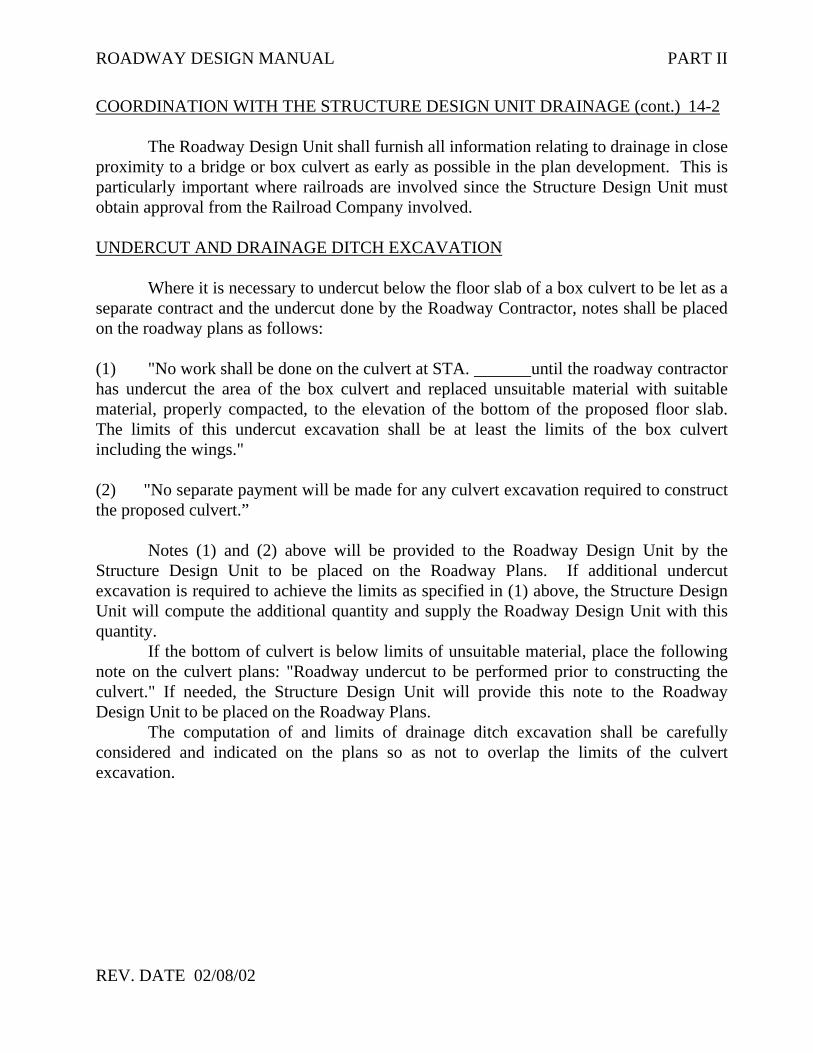
ROADWAY DESIGN MANUAL PART II
REV. DATE 02/08/02
COORDINATION WITH THE STRUCTURE DESIGN UNIT DRAINAGE (cont.) 14-2
The Roadway Design Unit shall furnish all information relating to drainage in closeproximity to a bridge or box culvert as early as possible in the plan development. This isparticularly important where railroads are involved since the Structure Design Unit mustobtain approval from the Railroad Company involved.
UNDERCUT AND DRAINAGE DITCH EXCAVATION
Where it is necessary to undercut below the floor slab of a box culvert to be let as aseparate contract and the undercut done by the Roadway Contractor, notes shall be placedon the roadway plans as follows:
(1) "No work shall be done on the culvert at STA. until the roadway contractorhas undercut the area of the box culvert and replaced unsuitable material with suitablematerial, properly compacted, to the elevation of the bottom of the proposed floor slab.The limits of this undercut excavation shall be at least the limits of the box culvertincluding the wings."
(2) "No separate payment will be made for any culvert excavation required to constructthe proposed culvert.”
Notes (1) and (2) above will be provided to the Roadway Design Unit by theStructure Design Unit to be placed on the Roadway Plans. If additional undercutexcavation is required to achieve the limits as specified in (1) above, the Structure DesignUnit will compute the additional quantity and supply the Roadway Design Unit with thisquantity.
If the bottom of culvert is below limits of unsuitable material, place the followingnote on the culvert plans: "Roadway undercut to be performed prior to constructing theculvert." If needed, the Structure Design Unit will provide this note to the RoadwayDesign Unit to be placed on the Roadway Plans.
The computation of and limits of drainage ditch excavation shall be carefullyconsidered and indicated on the plans so as not to overlap the limits of the culvertexcavation.

ROADWAY DESIGN MANUAL PART II
REV. DATE NOVEMBER 2007
COORDINATION WITH THE STRUCTURE DESIGN UNIT (continued) 14-2
GUARDRAIL ATTACHED TO BOX CULVERTS
All box culverts shall be reviewed immediately after proposed grades are set to determineif it will be necessary to attach guardrail posts to the top slab. The Structure Design Unitshall be advised of locations where this is required.
RIP RAP
Where rip rap will appear in both the bridge plans and roadway plans at the samesite, care shall be exercised in clearly defining the limits covered by each set of plans.
REVISIONS
When revisions occur in the roadway plans during plan development affectingareas where bridges or box culverts occur, the Roadway Design Project Design Engineershall be responsible for keeping the Structure Design Unit advised of all revisions thatwould affect them.
There are also several items of information, initially furnished on the structurerecommendation plans, which should be confirmed immediately prior to completing finalplans. These include points of guardrail attachment, drainage devices, and the location andtype of median barriers. See Part I, Chapter 6 for structure recommendation planinformation.

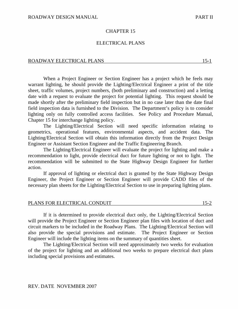
ROADWAY DESIGN MANUAL PART II
REV. DATE NOVEMBER 2007
CHAPTER 15
ELECTRICAL PLANS
ROADWAY ELECTRICAL PLANS 15-1
When a Project Engineer or Section Engineer has a project which he feels maywarrant lighting, he should provide the Lighting/Electrical Engineer a print of the titlesheet, traffic volumes, project numbers, (both preliminary and construction) and a lettingdate with a request to evaluate the project for potential lighting. This request should bemade shortly after the preliminary field inspection but in no case later than the date finalfield inspection data is furnished to the Division. The Department’s policy is to considerlighting only on fully controlled access facilities. See Policy and Procedure Manual,Chapter 15 for interchange lighting policy.
The Lighting/Electrical Section will need specific information relating togeometrics, operational features, environmental aspects, and accident data. TheLighting/Electrical Section will obtain this information directly from the Project DesignEngineer or Assistant Section Engineer and the Traffic Engineering Branch.
The Lighting/Electrical Engineer will evaluate the project for lighting and make arecommendation to light, provide electrical duct for future lighting or not to light. Therecommendation will be submitted to the State Highway Design Engineer for furtheraction.
If approval of lighting or electrical duct is granted by the State Highway DesignEngineer, the Project Engineer or Section Engineer will provide CADD files of thenecessary plan sheets for the Lighting/Electrical Section to use in preparing lighting plans.
PLANS FOR ELECTRICAL CONDUIT 15-2
If it is determined to provide electrical duct only, the Lighting/Electrical Sectionwill provide the Project Engineer or Section Engineer plan files with location of duct andcircuit markers to be included in the Roadway Plans. The Lighting/Electrical Section willalso provide the special provisions and estimate. The Project Engineer or SectionEngineer will include the lighting items on the summary of quantities sheet.
The Lighting/Electrical Section will need approximately two weeks for evaluationof the project for lighting and an additional two weeks to prepare electrical duct plansincluding special provisions and estimates.

ROADWAY DESIGN MANUAL PART II
REV. DATE 02/08/02
PLANS FOR LIGHTING 15-3
If lighting of the project is approved, the Lighting/Electrical Section will provideplans, special provisions and estimates to incorporate into the roadway plans. The ProjectEngineer or Section Engineer will be responsible for including lighting quantities on thesummary of quantities sheets.
The Lighting/Electrical Section will need approximately eight weeks after approvalto prepare lighting plans, special provisions and estimates.
If lighting for electrical duct is warranted, the Lighting/Electrical Engineer shouldadvise the Utility Agent to assure that any work by the utility company to provideelectrical service for lighting is included in the project utility agreement and projectestimate.
DESIGN GUIDELINES FOR LIGHTING WELCOME CENTERS 15-4AND REST AREAS
The IES (Illuminating Engineering Society) Lighting Handbook shall be used fordesign criteria except modified as follows:
(1) The design lux and uniformity shall not be excessively better than the minimum values listed in the handbook.
(2) Lighting will not be installed on the roadways leaving the rest area beyond the point where the car and truck traffic merge.
(3) Lighting will not be installed on the entrance to the rest area except in the immediate gore area where the rest area traffic separates from the main roadway.
(4) Lighting will not be installed on the interior roads except at gores where truck, car or camper traffic separates and special situation areas, such as curves, or beginning of curb section. Where interior roadway is lighted, an illumination level of 6.5 minimum maintained average lux with a uniformity ratio of four-to-one is to be used.
(5) Parking areas should be evaluated to determine how much of the area will beutilized for night parking. This night parking area may range from 50 to 100percent of the total parking area depending on the capacity and night trafficvolume. Night parking areas should be lighted to 6.5 minimum maintained average lux and uniformity of four-to-one. The remaining parking area should be lighted for security.

ROADWAY DESIGN MANUAL PART II
REV. DATE NOVEMBER 2007
CHAPTER 16
LANDSCAPE PLANS
LANDSCAPE PLANS 16-1
The Roadside Environmental Unit prepares separate plans for welcome centers,rest areas, landscape planting of roadways, junkyard screening, and reforestation.
The Roadway Design Unit is responsible for developing plans for roadwayslighting and parking areas of the welcome centers and rest areas. The Product ServicesUnit is responsible for providing and/or contracting utility construction plans.
Usually these plans are incorporated into the construction of the main line roadwayproject and the normal plan preparation methods are followed.
The landscape planting and junkyard screening projects are prepared entirely bythe Roadside Environmental Unit. The Special Design Engineer reviews these plans.Comments, recommendations and/or approvals are then returned to the RoadsideEnvironmental Unit for incorporation into the plans.
The final plans are transmitted to the Roadway Design Unit for inclusion into thefinal plans.
The Roadside Environmental Unit is also involved in planning for erosion controlmeasures as discussed in Chapter 11 of this manual.


ROADWAY DESIGN MANUAL PART II
REV. DATE NOVEMBER 2007
CHAPTER 17
SIGNING PLANS
SIGNING CONCEPTS FOR PRELIMINARY DESIGN 17-1
On urban freeways or interstate projects with complex interchanges, the designershould request the Traffic Congestion and Signing Unit to review the project for possiblesigning conflicts.
SIGNING PLANS 17-2
Signing plans are the responsibility of the Traffic Engineering and Safety SystemsBranch. Upon completion of signing plans and specifications, they will be submitted to theRoadway Design Unit for inclusion into the plans. Coordination of signing plans withTraffic Engineering is in accordance with Chapter 6/6 in the Policy and Procedure Manual.
Prior to the Pre-Let Field inspection, the Signing Engineer should provide theRoadway Engineer a copy of the signing plans. Roadway Design should design all trafficbarriers required to shield a sign structure within the clear zone of the highway, unlessbreakaway sign supports are utilized. If sign supports are placed in the median of a dividedhighway, Roadway Design will coordinate any revision to the plans with the HydraulicsUnit.
COORDINATION FOR SIGN SUPPORTS 17-3
Urban freeways often require large sign structures in the concrete median barrier.The detailing of these sign structures requires close coordination between TrafficCongestion and Signing, Structure Design, and Roadway Design.
Projects with proposed concrete median barrier sign foundations should be handledas follows:• Signing will provide both the Roadway Project Design Engineer and Structure Design
locations of all proposed Concrete Median Barrier Sign Foundations. This should beaccomplished by week 26 of the project flow chart.
• The Roadway Engineer will then provide Structure Design with the type of barrier,typical sections, and grades at each barrier location.

ROADWAY DESIGN MANUAL PART II
REV. DATE NOVEMBER 2007
COORDINATION FOR SIGN SUPPORTS (continued) 17-3
• The Roadway plans will call for Roadway Standard Drawings Std. No. 854.05Concrete Median Transition Barrier.
• Structure Design will furnish a special Concrete Median Barrier Foundation for SignAssembly detail for each location to Signing for inclusion in the signing plans. A copyof this detail will also be provided to Roadway for use in preparing median barrierquantities only (do not place in the Roadway Plans).
• The cost of the sign base and foundations are included in the cost of the overhead signassembly. The transition sections for median barrier are Roadway pay items.

ROADWAY DESIGN MANUAL PART II
REV. DATE NOVEMBER 2007
CHAPTER 18
UTILITY PLANS
COORDINATION DURING PRELIMINARY DESIGN 18-1
The Environmental Planning document should discuss the magnitude of impact ofthe utility conflicts. (See Policy and Procedures Manual, Chapter 20, Policy 1)
The Roadway Design Project Engineer should consider the utility conflicts duringthe preliminary design phase of the project. The Location and Surveys Unit should providegeneral information about the location and types of utilities during the scoping meeting forthe project.
When the utility impacts have been identified as high or medium, the RoadwayDesign Unit should submit preliminary plans to the Utility Agent, at the same time plans aresubmitted to the Hydraulics Unit. The project will then be reviewed by the Utility ConflictsCommittee to determine if revisions to the plans could reduce utility impacts.
UTILITY PLANS 18-2
The utilities by others and/or utility construction plans, special provisions andestimates are prepared by the Utilities Section of the Project Services Unit. Thisinformation will be incorporated into the roadway plans. See Chapter 20, Policy 1 of thePolicy and Procedure Manual for details.

REV. DATE NOVEMBER 2007
CHAPTER 19
EARTHWORK
PLOTTING OF CROSS-SECTION SHEETS 19-1
For most projects, cross-sections are plotted on a horizontal and vertical scale of 1″=10′. On mountainous projects with extremely high cuts and fills 1″ = 20’ might be morepractical. In all cases horizontal and vertical scales should be the same. Half-size plots aresent out with plans having over 30 cross-section sheets. Full-size plots are sent out onprojects with 30 or less cross-section sheets. If the Division request full-size plots for stakeout and construction purposes, these should be provided.
USE OF CADD FOR EARTHWORK 19-2
Most cross sections will be created from a DTM (Digital Terrain Model) originatingfrom Location and Surveys Unit or the Photogrammetry Unit. Geopak can be utilized toplot existing cross-sections, and complete proposed templates and earthwork. (Refer toGeopak Reference Manuals for procedures.)
EARTHWORK BALANCE SHEET 19-3
An earthwork balance sheet is required in the project file. Furnish a copy to theGeotechnical Engineering Unit on projects with available subsurface plans. Adhere to thefollowing guidelines when preparing the Earthwork Balance Sheet:
A. BREAKDOWN QUANTITIES AS FOLLOWS:
1. Summary points at every 3,000’ ±.2. Summary points end/begin at each bridge (stream or grade separation).3. Summary points end/begin near each major at-grade multi-lane intersection or at-
grade railroad crossing.4. Separate Y line, ramp, loop and other major construction items from mainline
earthwork, but include in the respective summary.5. On widening projects, respective summaries are provided for right and left side if
the material cannot be hauled across traffic.6. On existing divided facilities to be widened, respective summaries are provided
for right side, left side and median widening if the material cannot be hauledacross traffic.
7. Projects with complex construction phasing plans may require phasing of thesummary points. Coordinate phasing with the Division and The Traffic ControlUnit.

REV. DATE NOVEMBER 2007
EARTHWORK BALANCE SHEET (continued) 19-3 B. Include recommendations from the Geotechnical Engineering Unit and/or the Soils
and Foundation Section as follows:
1. Shrinkage Factor – (See Figure 1)
2. Loss Due to Clearing and Grubbing - This volume is estimated for loss in cuts ofup to one (1) foot in depth. Any loss in fills is included in the shrinkage factor.
3. Undercut Excavation - A recommendation for excavating benches at grade points
and removing unsuitable material below subgrade. This normally should bewasted, but in certain conditions can be used in embankments.
4. Top Soil on Borrow Pits - On projects requiring borrow material, an additional
5% of the total borrow should be computed for replacing the top soil on theborrow pit.
5. Rock – “Hard Rock” is only shown on the Earthwork Balance Sheet. All rock on
the project should be used in embankments before using suitable excavation andshould be computed on a one-to-one basis unless recommendations specifyotherwise.
The earthwork balance sheet, shown in Part II, 19-3, F-2, (with numbered columns)is for use with the descriptions below.
C. The information for a basic Earthwork Balance Sheet should be listed as follows:
1. List, in column one, the survey line reference and beginning station for eachsummary point.
2. Record, in column two, the ending station for each summary point.3. Show, in column three, the volume of all material excavated between summary
point stations (except material covered by other excavation pay items such asundercut excavation and drainage ditch excavation).
4. Column four contains volumes of "hard" rock that is excavated as a part ofunclassified excavation.
5. Record, in column five, volumes of material excavated beneath the roadwaysubgrade.
6. Show, in column six, volumes of any unclassified excavation that is not suitablefor roadway embankments.

REV. DATE NOVEMBER 2007
EARTHWORK BALANCE SHEET (continued) 19-3
7. Column seven contains Unclassified Excavation (less "hard" rock) volumes thatare suitable for constructing roadway embankments.
8. List the total embankment (include backfill for undercut) in column eight. Thisfigure is the volume of all the different materials used (do not include shrinkageor swell factors).
9. Show, in column nine, the volume of embankment that is to be constructed from"hard" rock. Use the "hard" rock portion of unclassified excavation, before theearth, to construct embankments within each summary point.
10. Show, in column ten, the volume of embankment that is to be constructed fromearth.
11. Column eleven reflects the actual volume of material needed to construct theembankment. A shrinkage factor must be applied to the earth portion and then the"hard" rock is added if applicable. Shrinkage and swell factors do no apply to"hard" rock unless specified by the Geotechnical Engineering Unit.
12. Column twelve shows the amount of borrow material needed to constructembankments after the suitable excavation (rock and earth) has been utilizedwithin the summary points.
13. Any "hard" rock excavation not utilized in embankments must have the volumelisted in column thirteen.
14. Record, in column fourteen, the volume of any suitable excavation (undercut orunclassified) not utilized in embankments. Exclude "hard" rock.
15. In column fifteen, record the volume of excavation (unclassified or undercut) thatdoes not have the necessary properties to be used in embankments.
16. Column sixteen shows the summation of volumes recorded in columns thirteen,fourteen, and fifteen.
After the listing of the summary points is completed, a "TOTAL" is needed. Total eachrespective column, three through sixteen. Make earthwork adjustments after the "TOTAL"as follows:
1. "Loss due to clearing and grubbing" volumes, recommended by the GeotechnicalEngineering Unit, are to be deducted from columns three and seven. This figurealso needs to be deducted from columns fourteen and sixteen on waste projects oradded to column twelve on borrow projects.
2. "Hard" rock waste, used to replace borrow, is to be added in column nine. It mustbe deducted from columns ten, twelve, thirteen and sixteen.

REV. DATE : 04/01/03
EARTHWORK BALANCE SHEET (continued) 19-3
3. Another line of adjustment is needed to "Adjust for rock waste." The volume ofrock used to replace borrow should have the shrinkage factor applied (example:a project with 20% shrinkage should have this volume multiplied by 0.20). Thisadjustment must be deducted from columns eleven and twelve because theshrinkage factor was applied to the material within the summary points, but hardrock is not subject to the shrinkage factor.
4. Any earth waste to replace borrow should be deducted from columns twelve,fourteen, and sixteen.
5. Borrow projects with graded shoulder sections require a line of adjustment withvolumes for shoulder material shown in columns eight and ten. These volumes,increased by the shrinkage factor, should show in columns eleven and twelve.Curb and gutter or shoulder trench sections do not need to be included. Projects,with enough usable waste material to build the graded shoulder section, shouldhave a separate pay item of "Shoulder Borrow" which reflects this volume. Donot cover shoulder borrow within the earthwork balance sheet. This should beshown at the bottom of the sheet (below the grand total of earthwork balancesheet items). Do not use the "Shoulder Borrow" pay item on projects with the"Borrow Excavation" pay item.
6. Additional undercut (undercut not shown on plans such as grade point undercut,contingency undercut, etc.) should have an earthwork adjustment line if otherundercut is shown within the summary points. This volume is to show in columnsfive, eight, ten, fifteen and sixteen. List this volume in column fourteen (insteadof fifteen) if undercut is suitable. Show this volume, increased by the shrinkagefactor, in columns eleven and twelve. Projects with no undercut shown within thesummary points can have this volume listed, as estimated undercut, at the bottomof the sheet (below the grand total of earthwork balance sheet items). Using thismethod should result in the undercut quantity shown on the earthwork summaryand the quantity on the summary of quantities being identical.
Other adjustments (select borrow, rock swell, flyash, etc.) may be warranted on selectprojects. The method of including this information on the earthwork balance sheet can varydue to recommendation format.
Total each respective column, three through sixteen, after the above adjustments arecomplete. This will be the "Grand Totals" on waste projects and "Project Totals" on borrowprojects. Borrow projects need an additional 5% added to the figure shown in columntwelve of the " Project Totals" line. This is an "Estimated 5% for Replacing Topsoil onBorrow Pits" which must be included in the "Grand Total" of borrow projects.

REV. DATE NOVEMBER 2007
EARTHWORK BALANCE SHEET (continued) 19-3
"Say" quantities should be shown beneath the "Grand Totals" for any volumes shown incolumns that require a pay item.
The following note should be included on each Earthwork Balance Sheet: Note: “Earthworkquantities are calculated by the Roadway Design Unit. These quantities are based in part onsubsurface data provided by the Geotechnical Engineering Unit.”
The “Earthwork Summary” shown in the Roadway Plans shall be restricted to informationshown in columns one, two, three, five, eleven, twelve and sixteen of the EarthworkBalance Sheet (Part II, 19-3, F-2). Do not show the shrinkage factor in the embankment +%column (eleven) of the Earthwork Summary in the plans.
An example of the earthwork balance sheet for a “Borrow” project shows in Part II, 19-3,F-3. See Part II, 19-3, F-4 for an example showing a “Waste” project.
The Plan Review Section of the Project Services Unit will assist you at your request.
NOTE ON CROSS SECTIONS 19-4(EXCLUDING LUMP SUM GRADING AND LUMP SUM BIDPROJECTS)
The following note shall be shown on the first cross-section or cross sectionsummary sheet: Note: “Quantities are approximate only. The Resident Engineer will re-cross-section thework accurately when the project is staked out. These cross-section notes will be used incomputing the final quantities for which the contractor will be paid.”
NOTE FOR LUMP SUM GRADING 19-5
The following note shall be shown on the first cross-section sheet, the EarthworkSummary, and the Pavement Removal Summary on Lump Sum Grading projects:
Note: Approximate quantities only. Unclassified Excavation, Borrow Excavation, ShoulderBorrow, Fine Grading, Clearing and Grubbing, Breaking of Existing Pavement, andRemoval of Existing Pavement will be paid for at the contract lump sum price for“Grading.”
For additional information, see Chapter 11 of the Policy and Procedure Manual.


REV. DATE NOVEMBER 2007


REV. DATE NOVEMBER 2007

REV. DATE NOVEMBER 2007

REV. DATE NOVEMBER 2007


ROADWAY DESIGN MANUAL PART II
REV. DATE NOVEMBER 2007
CHAPTER 20
FIELD INSPECTION
PLOTTING OF CROSS-SECTION SHEETS 20-1
The field inspection review questions for final design, combined and Pre-Letinspections are available on website:
http://www.ncdot.org/doh/preconstruct/highway/roadway/manuals/
To expedite and improve the coordination between Construction and Designpersonnel in scheduling and holding field inspections, the following suggestions should beadhered to:
(1) Make sure everyone involved in project development is aware that flow chartdates are the latest dates for activities to occur.
(2) The Roadway Design Project Engineer should send field inspection plans tothe Division prior to the Flow Chart date, to allow ample time for planfamiliarization.
(3) Design personnel should take notes at field inspections so that plan revisionscan begin prior to receiving the Division's Field Review letter.
(4) For projects with tight schedules, the Roadway Design Project Engineershould make preliminary plans available to the Division for familiarizationprior to submittal for field inspection.
(5) Field inspection dates should be established by phone between the RoadwayDesign Project Engineer and the appropriate Division representative.Memorandum transmitting field inspection plans should indicate time, date,and location for field inspection.
(6) Send only the questions that pertain to the project. Do not send the entire listof questions.
(7) It is the responsibility of the Roadway Design Project Engineer to advise theStructure Design Unit when they schedule a preliminary and/or final fieldinspection. This will allow them to review the project and determine if theyshould attend the field inspection.
Determine which one (1) of three (3) question sets (final design, combined or pre-let)is appropriate for your field inspection letter. Once you have selected the properquestion set, edit the questions to delete, add, and /or revise the questions that pertainto the project.


ROADWAY DESIGN MANUAL PART II
REV. DATE NOVEMBER 2007
ADDITIONAL INFORMATION ON PUBLIC HEARINGS 21-3
(1) The Roadway Design Project Engineer will be responsible for the hearing mapreview. The hearing map should be reviewed by the following:
(A) Federal Highway Administration (if applicable)(B) State Highway Design Engineer(C) Public Involvement and Community Studies(D) State Roadway Design Engineer and Assistant State Roadway Design Engineer(E) Program Development - TIP Development Unit(F) Traffic Engineering and Safety Systems Branch, Congestion Management
Section(G) Signals and Geometrics Section (if applicable)(H) Project Development and Environmental Analysis Branch(I) Hydraulics Unit (if applicable)(J) Structure Design Unit (if applicable)(K) Public Affairs(L) Geotechnical Engineering Unit(M) MPO Representative (If in MPO area).(N) Division Staff (Division Engineer or Division Construction Engineer).(O) Right-of-Way Branch representative.(P) Consultant Coordination Section (If any part of the project is to be done by a
Private Engineering Firm).(Q) Corps of Engineers (If applicable).
At the design public hearing, the Roadway Design Project Engineer orappointed representative should prepare good notes of the oral commentsrendered at the hearing. These notes will be used in developing the agenda for thePost Design Hearing Meeting. (The Public Hearing transcript may not beavailable in all cases; the notes will provide a good summary in case the transcriptis not available.)
After the comment period is over, the Roadway Design Project Engineer willcontact the Citizens Participation Unit to obtain a copy of all written commentsreceived following the hearing. The Project Engineer will then begin to compilethe summary of comments, which will be used as an agenda for the post hearingmeeting. In order to address the public’s concerns in a timely manner, the posthearing meeting date should ideally be held no longer than six weeks after thedate of the design public hearing. (There may be extenuating circumstances oradditional studies that may delay this date).
Post Design or Combined Public hearing Meeting
The Roadway Design Project Engineer will set the post hearing meeting date and will invite all the attendees who were invited to the design public hearing map review. In addition, if the project is extremely controversial or not favored by the public, it may be appropriate to invite the Board of Transportation Members. In a

ROADWAY DESIGN MANUAL PART II
REV. DATE NOVEMBER 2007
ADDITIONAL INFORMATION ON PUBLIC HEARINGS (Continued) 21-3
situation where there is extreme controversy, the hearing comments should be discussed with the Public Involvement and Community Studies Unit, Roadway Design Assistant Unit Head and Unit Head to determine the appropriate attendees.
Following the post hearing meeting, the Roadway Design Project Engineer will prepare the post hearing meeting minutes or summary. These minutes are to be reviewed by the Roadway Design Assistant Unit Head and should be prepared as a memorandum to the Post Hearing Meeting Attendees for the State Roadway Engineer’s signature.
These minutes should be very formal and informative. They should also stateresolution of issues or issues that are to require further studies. Also, any lettersfrom citizens that seek additional information or require a written response shouldbe discussed to determine who will prepare the written response.
(2) Once the hearing map review has been held, the Public Hearing Officer may need thefollowing information from the Project Engineer.
(A) Hearing map(B) Two (2) replicas of hearing map, one for a relocation study and one for
display prior to the hearing.(C) Information for public handouts at hearing.
NOTE: Contact between the Public Hearing Officer and the Project Engineer shall beimmediately after a hearing map is reviewed for a public hearing.
(3) Combined public hearing maps are not to be prepared on aerial mosaics withoutapproval of the Public Hearing officer.
(4) The Corridor Public Hearing Map is to be reviewed by the State Highway DesignEngineer.
ROADWAY DESIGN MANUAL PART II
REV. DATE NOVEMBER 2007
CHAPTER 22
CHECK LISTS
PURPOSE 22-1
Checklists for Preliminary, Right of Way, and Final Plans are provided for thedesigner's assistance in the preparation of plans, specifications, and estimates.
A checklist for final plans shall be turned in when final plans are submitted to thePlan Review Project Engineer for review. These lists are available from the website:
http://www.ncdot.org/doh/preconstruct/ps/specifications/specifications_provisions.html


ROADWAY DESIGN MANUAL PART II
REV. DATE NOVEMBER 2007
CHAPTER 23
STANDARD FORMS
STANDARD FORMS 23-1
Standard forms are provided for various activities that are conducted by theRoadway Design. Copies of these forms are available in the Records and DocumentsGroup of the Project Services Unit. The calculation of quantities forms are available fromthe website:
http://www.ncdot.org/doh/preconstruct/ps/contracts/standards/quantities/default.html
The following forms are also available on the above website:Various ChecklistsGeneral Project NotesStandards ListsSpecial Detail Requests
There are also template files available on the Roadway Design Unit website:
http://www.ncdot.org/doh/preconstruct/highway/roadway/V8/
These include:Geopak Templates
CriteriaEarthwork
Excel TemplatesBalance CardVarious Summary SheetsEarthwork XSC VolumesRight of Way Parcel Sheets
Access Templates for Compbook Quantities


ROADWAY DESIGN MANUAL PART II
REV. DATE NOVEMBER 2007
CHAPTER 24
REFERENCE MATERIAL
REFERENCE MATERIAL 24-1
There is no limit to the amount of reference material available to Roadway DesignUnit personnel. Research information is filed in the Value Management Section (See theDevelopment and Publication Engineer); also, there is a large library in the Research andAnalysis Group of the Environmental, Planning, and Local Governmental Affairs ProgramDevelopment Branch.
To supplement the Policy and Procedures Manual and the Design Manualspecifically prepared for Roadway Design personnel, a list of some of the more prominentDivision of Highway manuals, books, etc., are listed below. If assistance is needed inlocating this material, the Research and Production Engineer will provide it.(1) Employee Handbook(2) Manual for Construction Layout(3) North Carolina State Personnel Manual(4) Field Fiscal Procedures Manual(5) Route Location and Design by Thomas F. Hickerson(6) Roadway Standard Drawings(7) Standard Specifications for Roads and Structures(8) Roadway Design Policy and Procedures Manual(9) Roadway Design Manual(10) Structure Design Policy and Procedures Manual(11) Structure Design Manual(12) Highway Capacity Manuals(13) Guidelines for Placement of Garbage Collection Containers on State Highway
System Right of Way(14) Guidelines Curb Cuts and Ramps for Disabled Persons(15) Manual on Driveway Entrance Regulations(16) Highway Action Plan(17) North Carolina Transportation Improvement Program(18) Subdivision Roads - Requirements and Minimum Construction Standards(19) Guidelines for Drainage Studies(20) Construction Manual(21) Right of Way Manual(22) Policies and Procedures for Accommodating Utilities on Highway Rights of Way(23) Outdoor Advertising(24) Property Survey Manual

ROADWAY DESIGN MANUAL PART II
REV. DATE 03/10/03
REFERENCE MATERIAL (continued) 24-1
(25) Survey Manual(26) Manual on Uniform Traffic Control Devices(27) A Guide to North Carolina Laws Related to Traffic Engineering Operations(28) A Policy on Geometric Design of Highways and Streets(29) Road and Highway Laws of North Carolina(30) Motor Vehicle Laws of North Carolina(31) General Ordinances of North Carolina(32) North Carolina Administrative Code(33) Traffic Count Books(34) Federal Aid Policy Guide(35) County Map Books(36) Book I and Book II - Traffic Engineering Operating Manual(37) Guide for Resurfacing, Restoration and Rehabilitation (R-R-R) of Highways and
Street(38) Federal Laws, Regulations, and Material Relating to the Federal Highway
Administration(39) Roadside Environmental Unit Manual(40) Transportation and Traffic Engineering Handbook(41) Emergency Response Guidebook(42) N. C. Special Permits Manual(43) N. C. Administrative Procedures Act (Title 19A NCAC)(44) Roadside Design Guide (AASHTO)(45) Pay Item List(46) North Carolina Bicycle Facilities Planning and Design Guidelines(47) Transportation Planning Handbook (ITE)(48) Traffic Engineering Handbook (ITE)(49) Workplace Safety Manual(50) Other State Design Manuals, AASHTO Manuals, FHWA Publications and
reference material(51) Permits, Permit Drawings and Mitigation Publications(52) Roundabouts: An Informational Guide(53) Safety Policy and Procedure Manual(54) Traditional Neighborhood Development Street Design Guidelines

ROADWAY DESIGN MANUAL PART II
REV. DATE NOVEMBER 2007
OTHER PUBLICATIONS 24-2
The National Cooperative Highway Research Program was established in 1962 toprovide a continuing program of highway research. Their publications are morecommonly known as NCHRP'S. We make frequent use of their research material in ourdesigns. A list of their publications is available in the Alternative Delivery Library. (Seethe Research and Production Engineer in the Value Management Section).
Following are other publications available in the Alternative Delivery Library:
(1) Transportation Research Record(2) Texas Transportation Institute Report (3) Transportation Research News(4) Transportation Research Board - Special Report(5) Transportation Research Circular(6) Nat. Coor. Highway Research Program Synthesis(7) Nat. Coor. Highway Research Program Report(8) Nat. Coor. Highway Research Program(9) Highway Research Record(10) Highway Research Board
SECONDARY ROAD NAMES 24-3
A list of statewide secondary road numbers and names has been compiled for youruse in preparing plans. This list is available in the Alternative Delivery Library. (See theDevelopment and Publication Engineer in the Value Management Section).
Also, Secondary Road Name Inquiry System is available on the North CarolinaState, Department of Transportation’s WebPages, located at:
http://apps.dot.state.nc.us/srlookup/SecondaryRoads.aspx