Embed Size (px)
Citation preview

Modeling texture evolution during rolling process of AZ31 magnesium alloy with elastoplastic self consistent model
HUANG Shiyao, ZHANG Shaorui, LI Dayong, PENG Yinghong
State Key Laboratory of Mechanical System and Vibration, School of Mechanical and Power Energy Engineering, Shanghai Jiao Tong University, Shanghai 200240, China
Received 10 June 2010; accepted 8 October 2010
Abstract: To gain a better understanding about texture evolution during rolling process of AZ31 alloy, polycrystalline plasticity model was implemented into the explicit FE package, ABAQUS/Explicit by writing a user subroutine VUMAT. For each individual grain in the polycrystalline aggregate, the rate dependent model was adopted to calculate the plastic shear strain increment in combination with the Voce hardening law to describe the hardening response, the lattice reorientation caused by slip and twinning were calculated separately due to their different mechanisms. The elastoplastic self consistent (EPSC) model was employed to relate the response of individual grain to the response of the polycrystalline aggregate. Rolling processes of AZ31 sheet and ascast AZ31 alloy were simulated respectively. The predicted texture distributions are in qualitative agreement with experimental results. Key words: AZ31 alloy; texture; rolling process; elastoplastic self consistent (EPSC) model
1 Introduction
Magnesium alloys are promising light structural metals in aerospace and automobile applications because of their high specific strength and recyclability. Compared with other forming methods such as powder metallurgy technique, rapid solidification and equal channel angular extrusion, rolling process provides a common way that can fabricate large dimension products [1]. Recent experimental researches [2−3] show that the texture evolution during rolling process of AZ31 alloy has great impacts on its mechanical properties. For example, rolled sheets of AZ31 alloy show tension– compression yield asymmetry, which can be attributed to the formation of strong basal texture during rolling process. Thus, prediction of texture evolution in rolling process has attracted a lot of attention from the point of view of industrial significance.
Polycrystalline plasticity has been proven as a useful tool to simulate texture evolution in magnesium alloy during the last decade. STYCZYNSKI et al [4] performed the texture modeling of cold rolling by adopting a viscoplastic Taylor model, the best agreement
with experiment was achieved with a combination of basal ⟨a⟩ slip, prismatic ⟨a⟩ slip, pyramidal ⟨c+a⟩ slip and tensile twinning. WALDE and RIEDEL [5] simulated texture evolution during hot rolling process with viscoplastic selfconsistent (VPSC) model. AGNEW et al [6] also employed polycrystalline plasticity model to study the hardening mechanism of AZ31 alloy and the development of internal strain.
Although there have been a lot of progresses in texture modeling of AZ31 alloy, we should note that most of the simulations were conducted with Taylor model or VPSC model. Simulation of texture evolution in AZ31 alloy during rolling process with elastoplastic self consistent (EPSC) model is not found. Research [7] showed that Taylor model could lead to the prediction of excessively high stresses or incorrect texture distribution for material with strong anisotropy. Compared with EPSC model, VPSC model does not account for hydrostatic stresses or for the elastic deformation component, and cannot be used to study internal stress evolution [8].
In this work, we implement EPSC model into the commercial finite element code ABAQUS/Explicit. Texture evolution during rolling processes of AZ31 sheet
Foundation item: Projects (50821003, 50405014) supported by the National Natural Science Foundation of China; Projects (10QH1401400, 10520705000, 10JC1407300) supported by Shanghai Committee of Science and Technology, China; Project (NCET070545) supported by Program for New Century Excellent Talents in University, China; Ford University Research Program, China
Corresponding author: LI Dayong; Tel/Fax: +862134206313; Email: [email protected] DOI: 10.1016/S10036326(11)608649
HUANG Shiyao, et al/Trans. Nonferrous Met. Soc. China 21(2011) 1348−1354 1349
and ascast AZ31 alloy are simulated respectively, and the predicted texture distributions are compared with the experimental results [1, 4]. The influence of grain numbers per element on the simulation result is also studied.
2 Crystal plasticity model
2.1 Single crystal plasticity model 2.1.1 Kinetics
The velocity gradient is expressed as
W D F F L + = ⋅ = −1 & ( 1 )
where F is the deformation gradient, D is the symmetric part of the deformation rate andW is the skew symmetric spin tensor. D and W can be decomposed into elastic parts (D e ,W e ) and plastic parts (D p ,W p ):
+ =
+ = p e
p e
W W W
D D D (2)
D p and W p are related to the plastic shear strain rate as
=
=
∑
∑
=
= n
n
1
p
1
p
α
α α
α
α α
γ
γ
&
&
R W
P D (3)
P α and R α can be defined as
( ) ( )
⊗ − ⊗ =
⊗ + ⊗ =
α α α α α
α α α α α
n m m n R
n m m n P
2 1 2 1
(4)
where the slip direction is designated by the unit vector m and the slip plane normal by the unit vector n, the superscript α is the number of deformation systems.
A single crystal constitutive rule [9] which relates the grain level plastic strain rate α γ& and shear stress
α τ is employed: m
g g a α
α
α
α α α τ τ
γ ⋅ ⋅ = & & (5)
where α g denotes the critical resolved shear stress, which describes the current strain hardening state of the crystal, α a & is the reference shear rate and m is the material rate sensitivity. The solution of α γ& is making use of tangential modulus method [10]. 2.1.2 Hardening model
An extended form of Vocetype hardening rule [11] is adopted here to describe the evolution of critical resolved shear stress (CRSS):
] exp 1 )[ ( ) ( 1
0 1 1 0
− − + + = = α
α α α α α α γ θ γ θ γ
g g g g g (6)
where α 0 g is the initial CRSS; α
1 g is the saturation stress; γ is the accumulated shear at the current instant;
α θ 0 and α θ 1 are the initial and final slopes of the hardening rate. In each increment, the actual hardening for each deformation system is updated by
β
α
αβ α
α γ γ
∆ = ∆ ∑ q g
g d d
(7)
where αβ q is introduced to describe the self and latent hardening, αβ q can be expressed in a form [12]:
αβ αβ δ ) 1 ( q q q − + = (8)
where q is latenthardening ratio. 2.1.3 Lattice reorientation by slip
A crystal orientation tensor Q, is used to define the orientation of the crystal coordinate system with respect to the global coordinate system. At the end of each increment, grain reorientation caused by slip can be calculated based on the following equation [13]:
1 1
exp − =
∆
− = ∑ n
n
n t Q R W Q α
α α γ& (9)
2.1.4 Lattice reorientation by twinning For magnesium alloys, twinning also plays an
important role in lattice reorientation. Predominant twin reorientation (PTR) scheme [14] is employed to calculate the contribution of twinning to the grain reorientation. The procedure is listed next. At each increment, the twinned fraction (∆V α,n ) in grain n associated with each twinning system α is calculated using the shear strain (∆γ α,n ) to which the twinning mode contributes
c
, ,
γ γ α
α n
n V ∆
= ∆ (10)
where γc is the characteristic shear of the twinning mode. Twinned fraction is accumulated after each increment:
∑ ∆ = steps c
, ,
γ γ α
α n
n V (11)
A summation over all grains and all twinning systems gives the volume fraction VR:
∑∑ ∆ = steps ,
, R
n
n V V α
α (12)
A threshold value (FT) for reorientation is defined by
R
E T V
V b a F + = (13)
where VE is the effective twinned fraction, VR is the total volume fraction of accumulated twins, and a and b are

HUANG Shiyao, et al/Trans. Nonferrous Met. Soc. China 21(2011) 1348−1354 1350
material constants. At every increment, if the accumulated twinned fraction of the most active twinning system exceeds threshold value, the whole grain is reoriented following the predominant twinning system. The new grain orientation can be calculated with the following equation [15]:
( )Q I n n Q − ⊗ = 2 twin (14)
where Qtwin is the orientation matrix after twinning reorientation; n is the normal twining plane; I is identity matrix. Then this reoriented grain is added to the effective twinned fraction, VE. As more grains are reoriented by twinning, FT increases by the increment of VE. Further reorientation by twinning is inhibited until VR catches up.
2.2 Elastoplastic self consistent (EPSC) model In the EPSC approach, each individual grain is
treated as an ellipsoidal elastoplastic inclusion embedded in the homogeneous effective medium (HEM) representing the polycrystalline aggregate. The calculation procedures of EPSC model in the current study are briefly summarized as follows.
The instantaneous elastoplastic tensor Lc for the individual crystal relates c σ & and strain rate Dc by
c c c : D L = σ & (15)
A similar relation is adopted to link the overall stress rate and strain rate by M L , M L is defined as the instantaneous elastoplastic tensor for HEM:
M M M : D L = σ & (16)
The strain rate in individual grain can be related to strain rate in the polycrystalline aggregate according to
M c c D A D = (17)
Ac is defined as
) ( ) ( M * 1
c * c L L L L A + + = − (18)
where * L is the constraint tensor for the ellipsoidal inclusion. * L is a function of M L and Eshelby’s tensor S as follows:
) ( M * S I L S L − = (19)
Lc and M L are unknown during each increment and have to be calculated selfconsistently until the condition that the average of the grain stresses increment coincides with the macroscopic stress increment is reached (Eq. (20)). Then, the stress of polycrystalline aggregate can be updated according to Eq. (21):
= M dσ ⟨dσc⟩ (20)
M new M, new M, dσ σ σ + = (21)
3 Simulation of texture evolution during rolling process
3.1 Rolling process of AZ31 sheet In this section, the model is applied to predicting
texture evolution during rolling process of AZ31 sheet. The simulation result is compared with the experiment outlined in LIANG et al [1] which is summarized as follows. The dimensions of initial sample were 80 mm×50 mm×9.8 mm. The roller temperature was selected at 673 K and the original sheets were maintained at room temperature. The rolling speed was 5 m/min. The thickness reduction was 20%. Texture distribution was measured by electron backscatter diffraction (EBSD). Figure 1 shows the texture distribution of original and deformed samples with the observed plane perpendicular to ND. The initial sample shows the 0002⟨ 0 1 10 ⟩ type texture, while the texture distribution in (0002) pole figure is a little scattered. The deformed sample shows stronger basal texture and the 0002⟨ 0 1 10 ⟩type texture does not exist.
Only one quarter of the initial sample is built in simulation due to symmetry. The C3D8R type of element (the 8 node solid brick elements with reduced integration in ABAQUS terminology) is employed to mesh the blank. The FE model consists of 120 elements, while each element represents 40 grains. The input texture (4 800 grains) is shown in Fig. 2. The grain orientation is assigned to each element randomly. For each individual grain, basal ⟨a⟩, prismatic ⟨a⟩, pyramidal ⟨c+a⟩ slip systems and tensile twinning systems are chosen as the deformation mechanisms of AZ31 alloy. The values of the parameters in elastic moduli are [16]: C11=58 GPa, C12=25 GPa, C13=20.8 GPa, C33=61.2 GPa, C55=16.6 GPa, and the values of the hardening parameters are listed in Table 1 [6]. The latent hardening ratios for slip systems are set to be 1.4, while it is set to be 4.0 for twinning system to represent that the dislocation movement is inhibited by twinning boundary.
Table 1 Plasticity parameters for AZ31 alloy (MPa) [6]
Mechanism g0 g1 θ0 θ1
Basal ⟨a⟩ 10 30 100 0
Prismatic ⟨a⟩ 55 80 500 0
Pyramidal ⟨c+a⟩ 60 90 1500 0
Tensile twinning 30 0 30 30
Figure 3 shows the contours of rolled sheet. The predicted texture is shown in Fig. 4. Compared with the input texture (Fig. 2), the 0002⟨ 0 1 10 ⟩ type texture

HUANG Shiyao, et al/Trans. Nonferrous Met. Soc. China 21(2011) 1348−1354 1351
Fig. 1 Texture distributions of initial and deformed samples [1]: (a) Initial (0002); (b) Initial ( 0 1 10 ); (c) Deformed (0002); (d) Deformed ( 0 1 10 )
Fig. 2 Initially texture (4 800 grains) for simulation: (a) (0002); (b) ( 0 1 10 )
disappears and a more concentrated basal texture is formed after rolling. This is in accordance with the
experimental result (Fig. 1). To gain a better understand ing on how the grain number in each element affects the

HUANG Shiyao, et al/Trans. Nonferrous Met. Soc. China 21(2011) 1348−1354 1352
simulation result, another simulation is performed with the same FE model. As a comparison, each element only contains five grains. A similar texture (Fig. 5) is
predicted with this model, but the texture distribution is scattered due to insufficient grain number. Hence, a large grain number can predict a smooth texture distribution.
Fig. 3 Contours of rolled sheet
Fig. 4 Predicted texture with 4800 grains: (a) (0002); (b) ( 0 1 10 )
Fig. 5 Predicted texture with 600 grains: (a) (0002); (b) ( 0 1 10 )
HUANG Shiyao, et al/Trans. Nonferrous Met. Soc. China 21(2011) 1348−1354 1353
However, both of the simulation results indicate that basal texture spreads along TD, while experiment result does not show the same distribution. There are two main reasons causing the difference between simulation result and experiment result. The experiment result in LIANG et al [1] was measured by EBSD, suggesting that a smaller grain number is detected which is different from the current simulation (4 800 grains and 600 grains). The difference of measured grain numbers can possibly lead to deviation between simulation and experiment. The influence of dynamic recrystallization is precluded in the current study to get a better computational efficiency. This assumption does not hold true in reality since dynamic recrystallization was observed during rolling process of AZ31 alloy [1]. Although researches [17−18] show that recrystallization in magnesium alloy does not lead to a distinct change in texture distribution, to make a quantitative comparison between the simulation result and the experiment result, further effort to consider the effect of dynamic recrystallization is necessary.
3.2 Rolling of cast material In this section, the model is applied to predicting
texture evolution during rolling of AZ31 cast material. The simulation result is compared with the experiment outlined by STYCZYNSKI et al [4], which is summarized as follows. The dimensions of initial sample were 50 mm×30 mm×6 mm. The rolling was carried out at room temperature. The rolling speed was 3 m/min. The thickness reduction was fixed to a true strain of 0.1 per pass to the total strain of 0.5. Texture distribution was measured by Xray diffractometer (XRD). When the observed plane is perpendicular to ND, the initial sample shows a randomly distributed texture, while the strong basal texture is formed after rolling process. The point with the highest intensity in deformed sample tilts a small angle away from ND, and the basal texture spreads along TD.
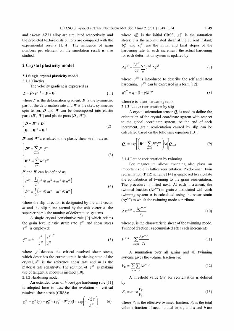
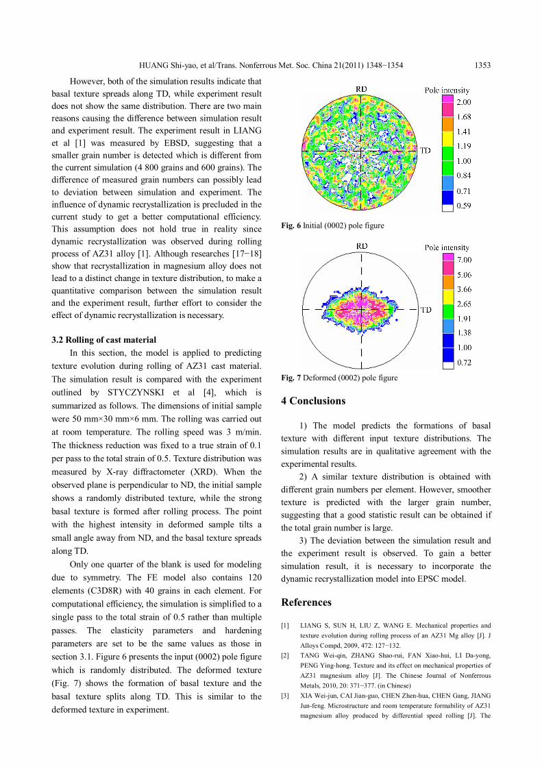
Only one quarter of the blank is used for modeling due to symmetry. The FE model also contains 120 elements (C3D8R) with 40 grains in each element. For computational efficiency, the simulation is simplified to a single pass to the total strain of 0.5 rather than multiple passes. The elasticity parameters and hardening parameters are set to be the same values as those in section 3.1. Figure 6 presents the input (0002) pole figure which is randomly distributed. The deformed texture (Fig. 7) shows the formation of basal texture and the basal texture splits along TD. This is similar to the deformed texture in experiment.
Fig. 6 Initial (0002) pole figure
Fig. 7 Deformed (0002) pole figure
4 Conclusions
1) The model predicts the formations of basal texture with different input texture distributions. The simulation results are in qualitative agreement with the experimental results.
2) A similar texture distribution is obtained with different grain numbers per element. However, smoother texture is predicted with the larger grain number, suggesting that a good statistic result can be obtained if the total grain number is large.
3) The deviation between the simulation result and the experiment result is observed. To gain a better simulation result, it is necessary to incorporate the dynamic recrystallization model into EPSC model.
References
[1] LIANG S, SUN H, LIU Z, WANG E. Mechanical properties and texture evolution during rolling process of an AZ31 Mg alloy [J]. J Alloys Compd, 2009, 472: 127−132.
[2] TANG Weiqin, ZHANG Shaorui, FAN Xiaohui, LI Dayong, PENG Yinghong. Texture and its effect on mechanical properties of AZ31 magnesium alloy [J]. The Chinese Journal of Nonferrous Metals, 2010, 20: 371−377. (in Chinese)
[3] XIA Weijun, CAI Jianguo, CHEN Zhenhua, CHEN Gang, JIANG Junfeng. Microstructure and room temperature formability of AZ31 magnesium alloy produced by differential speed rolling [J]. The

HUANG Shiyao, et al/Trans. Nonferrous Met. Soc. China 21(2011) 1348−1354 1354 Chinese Journal of Nonferrous Metals, 2010, 20: 1247−1253. (in Chinese)
[4] STYCZYNSKI A, HARTIG C, BOHLEN J, LETZIG D. Cold rolling textures in AZ31 wrought magnesium alloy [J]. Scripta Mater, 2004, 50: 943−947.
[5] WALDE T, RIEDEL H. Modeling texture evolution during hot rolling of magnesium alloy AZ31 [J]. Mater Sci Eng A, 2007, 443: 277−284.
[6] AGNEW S, BROWN D, TOMÉ C. Validating a polycrystal model for the elastoplastic response of magnesium alloy AZ31 using in situ neutron diffraction [J]. Acta Mater, 2006, 54: 4841−4852.
[7] LEBENSOHN R, DAWSON P, KERN H, WENK H. Heterogeneous deformation and texture development in halite polycrystals: comparison of different modeling approaches and experimental data [J]. Tectonophysics, 2003, 370: 287−311.
[8] CLAUSEN B, TOMÉ C, BROWN D, AGNEW S. Reorientation and stress relaxation due to twinning: Modeling and experimental characterization for Mg [J]. Acta Mater, 2008, 56: 2456−2468.
[9] HUTCHINSON J. Bounds and selfconsistent estimates for creep of polycrystalline materials [J]. Proc R Soc Lond A, 1976, 348: 101−127.
[10] PEIRCE D, ASARO R, NEEDLEMAN A. Material rate dependence and localized deformation in crystalline solids [J]. Acta Metall, 1983, 31: 1951−1976.
[11] AGNEW S, YOO M, TOMÉ C. Application of texture simulation to understanding mechanical behavior of Mg and solid solution alloys containing Li or Y [J]. Acta Mater, 2001, 49: 4277−4289.
[12] PEIRCE D, ASARO R, NEEDLEMAN A. An analysis of nonuniform and localized deformation in ductile single crystals [J]. Acta Metall, 1982, 30: 1087−1119.
[13] SIMO J, VUQUOC L. A threedimensional finitestrain rod model: Part II—Computational aspects [J]. Comput Methods Appl Mech Engrg, 1986, 58: 79−116.
[14] TOMÉ C, LEBENSOHN R, KOCKS U. A model for texture development dominated by deformation twinning: Application to zirconium alloys [J]. Acta Metall, 1991, 39: 2667−2680.
[15] HOUTTE P. Simulation of the rolling and shear texture of brass by the Taylor theory adapted for mechanical twinning [J]. Acta Metall, 1978, 26: 591−604.
[16] STAROSELSKY A, ANAND L. A constitutive model for hcp materials deforming by slip and twinning: application to magnesium alloy AZ31B [J]. Int J Plasticity, 2003, 19: 1843−1864.
[17] PEREZPRADO M, RUANO O. Texture evolution during annealing of magnesium AZ31 alloy [J]. Scripta Mater, 2002, 46: 149−155.
[18] YANG P, MENG L, MAO W, CHEN L. Characteristics of hot compressed magnesium alloy AZ31 with initial textures analyzed by orientation mapping [J]. Mater Sci Forum, 2005, 495−497: 639−644.
基于弹塑性自洽模型的 AZ31 镁合金轧制过程的织构模拟
黄诗尧, 张少睿, 李大永, 彭颖红
上海交通大学 机械与动力工程学院,机械系统与振动国家重点实验室,上海 200240
摘 要:为了更好地研究镁合金轧制过程的织构演变,对商用有限元软件 ABAQUS/Explicit 的用户材料接口 VUMAT 做二次开发,实现晶体塑性力学和有限元方法的耦合。对于单个晶粒,通过相关模型计算每个增量步的
塑性应变增量,Voce硬化模型计算应变硬化。由于变形机制的不同,分别计算滑移和孪晶引起的晶格旋转。采用
弹塑性自洽模型计算单晶体和多晶体之间的联系。应用编制的程序,分别模拟 AZ31 板材和 AZ31 铸件的轧制过
程。结果表明,该程序能够较好地预测轧制过程的织构演化。
关键词:AZ31镁合金;织构;轧制;弹塑性自洽模型 (Edited by LI Xiangqun)


![An efficient and robust VUMAT implementation of ......Johnson–Cook constitutive flow law [4], presented in Section 3, has been selected to be implemented into the Abaqus/Explicit](https://img.pdfslide.us/doc/110x75/5fe3c41bb9b06a735102500a/an-efficient-and-robust-vumat-implementation-of-johnsonacook-constitutive.jpg)


![Explicit Coupled Thermo-Mechanical Finite Element Model …ccc.illinois.edu/s/Reports08/Koric_S Explicit Thermal... · software ABAQUS/Explicit [2] using a VUMAT subroutine. The model](https://img.pdfslide.us/doc/110x75/5adcbee47f8b9a595f8bf147/explicit-coupled-thermo-mechanical-finite-element-model-ccc-explicit-thermalsoftware.jpg)