Embed Size (px)
Citation preview

VOLUME 1 of 1Rev. H
21822662
FIELD SERVICE MANUAL and PARTS CATALOG
DLW-1STUDIO SOUND
and 2 CHANNEL PREAMP
R
Sta rLinkSta rLinkInternet Jukebox

21822662
TABLE OF CONTENTSSECTION 1 - UNPACKING AND SYSTEM DESCRIPTION
Introduction ......................................................................................................................................................... 1-1
Features .............................................................................................................................................................. 1-2General Features ............................................................................................................................................ 1-2Service Features ............................................................................................................................................. 1-2
Unpacking Instructions ...................................................................................................................................... 1-3Exterior .......................................................................................................................................................... 1-3Installation Instructions ................................................................................................................................... 1-3Door ............................................................................................................................................................... 1-6
Visual Inspection ................................................................................................................................................ 1-6
Handy Case ......................................................................................................................................................... 1-6
Warranty Registration Card ............................................................................................................................... 1-6
Major Components ............................................................................................................................................. 1-7Core Computer .............................................................................................................................................. 1-7Touchscreen Monitor 15” ............................................................................................................................... 1-7Touchscreen Monitor 17” ............................................................................................................................... 1-7Credit Card Reader ........................................................................................................................................ 1-7UPS ............................................................................................................................................................... 1-7System Power Supply .................................................................................................................................... 1-7Transformer Assembly ................................................................................................................................... 1-7Rowelink Controller ........................................................................................................................................ 1-7Volume Control Unit ....................................................................................................................................... 1-8Audio/Video Controller ................................................................................................................................... 1-82 Channel Preamp ......................................................................................................................................... 1-81000 Watt Audio Digital Power Amplifier ........................................................................................................ 1-8Output Transformers ...................................................................................................................................... 1-8Mars Bill Acceptor .......................................................................................................................................... 1-8
Specifications ................................................................................................................................................... 1-10
Lamps, Fuses, Circuit Breakers ........................................................................................................................1-11
SECTION 2 - INSTALLING THE HARD DRIVE AND TESTING
Installing the Hard Drive and Testing................................................................................................................ 2-1
Testing the Unit ................................................................................................................................................... 2-3
Peripherals .......................................................................................................................................................... 2-3Touchscreen ................................................................................................................................................... 2-3Bill Acceptor ................................................................................................................................................... 2-3Credit Card Reader ......................................................................................................................................... 2-3Connecting Speakers ...................................................................................................................................... 2-4
SECTION 3 - VENUE INSTALLATION
Introduction ......................................................................................................................................................... 3-1
Installing the Jukebox ........................................................................................................................................ 3-2
I

21822662
TABLE OF CONTENTS
II
Ethernet Cable Pin Out and Instructions .......................................................................................................... 3-3
Sound System Setup .......................................................................................................................................... 3-4Extension Speaker Operation ......................................................................................................................... 3-470 Volt Speakers ............................................................................................................................................ 3-4Low Impedance Speakers ............................................................................................................................... 3-44 Ohm Speakers ............................................................................................................................................. 3-48 Ohm Speakers ............................................................................................................................................. 3-4Extension Speaker Worksheet ........................................................................................................................ 3-5Transformer Wiring Diagram.......................................................................................................................... 3-12Speaker Synopsis ......................................................................................................................................... 3-148 Speaker Installation ................................................................................................................................... 3-1516 Speaker Installation .................................................................................................................................. 3-1632 Speaker Installation .................................................................................................................................. 3-17Remove Volume Control Unit (3 Wire) ........................................................................................................... 3-19Remove Volume Control Unit (4 Wire) ........................................................................................................... 3-20
SECTION 4 - ROUTINE SERVICE
Introduction ......................................................................................................................................................... 4-1
Collecting Money ................................................................................................................................................ 4-2
Preventive Maintenance .................................................................................................................................... 4-3Touchscreen ................................................................................................................................................... 4-3Exterior ........................................................................................................................................................... 4-3Interior ............................................................................................................................................................ 4-3
SECTION 5 - TROUBLESHOOTING
Introduction ......................................................................................................................................................... 5-1
DLW-1 LED’s ........................................................................................................................................................ 5-2Power Supply Board ....................................................................................................................................... 5-2
+9 V LED ................................................................................................................................................. 5-2+12 V LED ............................................................................................................................................... 5-2+24 V LED ............................................................................................................................................... 5-2
Rowelink Controller ......................................................................................................................................... 5-25VDC, 12VDC, 24VDC, and 24VAC LED’s ............................................................................................... 5-2IR RCV LED ............................................................................................................................................. 5-2KID RL TX LED ......................................................................................................................................... 5-2CC RL RX LED ......................................................................................................................................... 5-2CC RL TX LED.......................................................................................................................................... 5-2CRDT RL TX LED ..................................................................................................................................... 5-2CRDT STATUS LED ................................................................................................................................. 5-2
AV Controller .................................................................................................................................................. 5-2Power LED ............................................................................................................................................... 5-2Status LED............................................................................................................................................... 5-2Rowelink LED........................................................................................................................................... 5-2
Volume Control ............................................................................................................................................... 5-3Period LED (on the 10’s Digit) .................................................................................................................. 5-3Period LED (on the 1’s Digit) .................................................................................................................... 5-3
Power Amplifier ............................................................................................................................................... 5-3Yellow Clip LED ........................................................................................................................................ 5-3Red Overload LED .................................................................................................................................... 5-3
SECTION 3 - VENUE INSTALLATION (continued)

21822662
TABLE OF CONTENTS
III
Uninterruptable Power Supply ......................................................................................................................... 5-3Green LED (on top of UPS near the UPS Power Switch) .......................................................................... 5-3Building Wiring Fault LED ........................................................................................................................ 5-3
Computer Core Assembly ............................................................................................................................... 5-3+5 V LED ................................................................................................................................................. 5-3TX LED ..................................................................................................................................................... 5-3Link LED .................................................................................................................................................. 5-3RX LED .................................................................................................................................................... 5-3Hard Drive Green LED .............................................................................................................................. 5-3Hard Drive Yellow LED .............................................................................................................................. 5-3
Sequence of Operation ...................................................................................................................................... 5-4
Block Diagram - Studio Sound .......................................................................................................................... 5-6
Block Diagram - 2 Channel Preamp ............................................................................................................... 5-12
Wiring Diagram - 2 Channel Preamp.............................................................................................................. 5-14
Troubleshooting Charts .................................................................................................................................... 5-18
SECTION 6 - NETWORK
Introduction ......................................................................................................................................................... 6-1
Where to Install the Designated Line and Router ........................................................................................... 6-2
Installing the Designated Line........................................................................................................................... 6-3DSL ................................................................................................................................................................ 6-3Dial Up ........................................................................................................................................................... 6-3
Installing the Router ........................................................................................................................................... 6-4Introduction ..................................................................................................................................................... 6-4Description ..................................................................................................................................................... 6-4
Steps to Install the Router in the Location ....................................................................................................... 6-5
Standard Phone Cable Pin Out and Sources ................................................................................................... 6-6
SECTION 7 - USING THE DLW-1
Introduction ......................................................................................................................................................... 7-1
Operating the DLW-1 Jukebox........................................................................................................................... 7-2Approaching the Jukebox ................................................................................................................................ 7-2
Attract Loop ............................................................................................................................................. 7-2Getting Started ......................................................................................................................................... 7-2Paying to Use the System ....................................................................................................................... 7-2
Using the System ........................................................................................................................................... 7-3Selecting Local Music .............................................................................................................................. 7-3Search All Music on the DLW-1 Network .................................................................................................. 7-3Selecting Music from the Network ............................................................................................................ 7-3Buy CD Button ......................................................................................................................................... 7-3
SECTION 5 - TROUBLESHOOTING (continued)

21822662
TABLE OF CONTENTS
IV
Operating the DLW-1 Jukebox - Short Sheet ................................................................................................... 7-4Jukebox Music Station .................................................................................................................................... 7-4
To Select an Album .................................................................................................................................. 7-4To Select a Song ...................................................................................................................................... 7-4To Purchase an Album ............................................................................................................................. 7-4
SECTION 8 - EXTRANET
Introduction ......................................................................................................................................................... 8-1
General Questions for Internet Beginners ........................................................................................................ 8-2Clicking .......................................................................................................................................................... 8-2Pull-down menus ............................................................................................................................................ 8-2Using the “GO” button ..................................................................................................................................... 8-2How do I return to the previous pages ............................................................................................................. 8-2Downloading ................................................................................................................................................... 8-2Printing ........................................................................................................................................................... 8-2
General Questions for Everyone ....................................................................................................................... 8-3How do I access the Extranet? ....................................................................................................................... 8-3My username and password ........................................................................................................................... 8-3How do I get a username and password? ........................................................................................................ 8-3How do I change my username and password? .............................................................................................. 8-3What if I forget my username or password? .................................................................................................... 8-3Who can view my account? ............................................................................................................................ 8-3How do I get to each section’s home page? .................................................................................................... 8-3
Revenue Reports ................................................................................................................................................ 8-4
Usage Reports ..................................................................................................................................................... 8-4
Music Reports ...................................................................................................................................................... 8-4
System Reports ................................................................................................................................................... 8-4What are system reports? .............................................................................................................................. 8-4How often are system reports carried out? ...................................................................................................... 8-4How to read system reports ............................................................................................................................ 8-4Can I find out what’s wrong with a unit that is not working properly? ................................................................ 8-4What to do if a unit is not working ................................................................................................................... 8-4
Update music ...................................................................................................................................................... 8-5Adding, deleting albums ................................................................................................................................. 8-5Auto suggest .................................................................................................................................................. 8-5Music advisor .................................................................................................................................................. 8-5Manual select/remove ..................................................................................................................................... 8-6What is the maximum number of albums I can add to a location’s system each month? ................................ 8-6How long does it take to process my request to add or delete albums? .......................................................... 8-6Can I see a list of albums on each location’s DLW-1 list? ............................................................................... 8-6
Edit Profile .......................................................................................................................................................... 8-7What can I edit? ............................................................................................................................................. 8-7How can I edit? ............................................................................................................................................... 8-7
SECTION 7 - USING THE DLW-1 (continued)

21822662
TABLE OF CONTENTS
V
SECTION 9 - 2 CHANNEL SOUND SYSTEM....................................................................... 9-1Acoustical Compensation (Equalizer Tone Controls) ....................................................................................... 9-3Equalizer Settings .......................................................................................................................................... 9-3Soft and Highly Absorbent Rooms .................................................................................................................. 9-4Average or Moderately Absorbent Rooms ....................................................................................................... 9-5Hard or Non-Absorbent Rooms ....................................................................................................................... 9-5
SECTION 10 - OPERATOR SCREENS .............................................................................. 10-1Service Mode Map ........................................................................................................................................ 10-2Main Menu.................................................................................................................................................... 10-4System Auditing ........................................................................................................................................... 10-4Collection ..................................................................................................................................................... 10-5Pricing and Play Option ................................................................................................................................ 10-5Song Play Order ........................................................................................................................................... 10-6Credit Pricing ................................................................................................................................................ 10-6Add Free Credits .......................................................................................................................................... 10-7Autoplay Mode ............................................................................................................................................. 10-7Clear Credit/Clear Queue .............................................................................................................................. 10-8Recover Credits/Recover Queue .................................................................................................................... 10-8Recover Queue ............................................................................................................................................. 10-9Keypad ......................................................................................................................................................... 10-9Recover Credits .......................................................................................................................................... 10-10Keypad ....................................................................................................................................................... 10-10Hardware/Diagnostics .................................................................................................................................. 10-11Calibrate Touchscreen ................................................................................................................................. 10-11Rowelink Configuration ................................................................................................................................ 10-12System Configuration ................................................................................................................................. 10-12Pricing Setup .............................................................................................................................................. 10-13Audio Equalizers ........................................................................................................................................ 10-13Audio Volume Presets ................................................................................................................................ 10-14Audio Modes - Input Select ......................................................................................................................... 10-15Audio Modes - Muting ................................................................................................................................. 10-15Audio Modes - Output Mode ....................................................................................................................... 10-16Remote Control Setup - Parameters ........................................................................................................... 10-17Remote Control Setup - IR Settings ............................................................................................................ 10-18Remote Control Setup - VCU Settings ........................................................................................................ 10-19Microphone Setup - Setup .......................................................................................................................... 10-20Microphone Setup - Routing ........................................................................................................................ 10-20System Settings ......................................................................................................................................... 10-21Network Settings ........................................................................................................................................ 10-21System Diagnostics ................................................................................................................................... 10-21Quick Diagnostics ...................................................................................................................................... 10-22Network Diagnostics ................................................................................................................................... 10-22Application Logs ......................................................................................................................................... 10-22Update Controller ........................................................................................................................................ 10-23Configuration Summary............................................................................................................................... 10-23Music Filter ................................................................................................................................................ 10-23Spanish User Interface ................................................................................................................................ 10-24Adding a BGM (Background Music) Unit ..................................................................................................... 10-25Adding Microphones ................................................................................................................................... 10-26Separate Volume Control of Speaker Zones ................................................................................................ 10-29Keypad ....................................................................................................................................................... 10-31

21822662
TABLE OF CONTENTS
VI
SECTION 11 - PARTS CATALOG ........................................................................................11-1Introduction ....................................................................................................................................................11-3
Catalog Description .................................................................................................................................11-3Parts List Description ..............................................................................................................................11-3Ordering Replacement Parts ...................................................................................................................11-3
Main Door Assembly - External View - 17” Flat Screen ..................................................................................11-4Main Door Assembly - External View - 15” Flat Screen ..................................................................................11-6Main Door Assembly - Internal View - 15” and 17” Flat Screen .......................................................................11-8Shell Assembly - Internal View - Studio Sound ............................................................................................. 11-12Shell Assembly - Internal View - 2 Channel Preamp ..................................................................................... 11-13Shell Assembly - Internal View - Studio Sound and 2 Channel Preamp ........................................................ 11-14Core Computer Assembly ............................................................................................................................ 11-18I/O Subassembly (Left) ................................................................................................................................ 11-20I/O Subassembly (Right) .............................................................................................................................. 11-21Intermediate Board Assembly ...................................................................................................................... 11-22Computer Drive Door Assembly ................................................................................................................... 11-23Power Supply Assembly .............................................................................................................................. 11-24A/V Controller - 4 Channel ........................................................................................................................... 11-252 Channel Preamp ....................................................................................................................................... 11-26Output Transformer Assembly ...................................................................................................................... 11-27Rowelink Controller Assembly ...................................................................................................................... 11-28Hanger Bracket Assembly ........................................................................................................................... 11-29Accessory Equipment - 2 Channel Preamp Only ......................................................................................... 11-30


1) Read these instructions.
2) Keep these instructions.
3) Heed all warnings.
4) Follow all instructions.
5) Do not use this apparatus near water.
6) Clean only with a dry cloth.
7) Do not block any ventilation openings. Install inaccordance with the manufacturer’s instructions.
8) Do not install near any heat sources such asradiators, heat registers, stoves, or other apparatus(including amplifiers) that produce heat.
9) Do not defeat the safety purpose of the polar-ized or grounding-type plug. A polarized plug has twoblades with one wider than the other. A groundingtype plug has two blades and a third grounding prong.The wide blade or the third prong are provided foryour safety. If the provided plug does not fit into youroutlet, consult an electrician for replacement of theobsolete outlet.
IMPORTANT SAFETY INSTRUCTIONS
10) Protect the power cord from being walked onor pinched, particularly at plugs, convenience recep-tacles, and the point where they exit from the appara-tus.
11) Only use the attachments/accessories specifiedby the manufacturer.
12) Use only with the cart, stand,tripod, bracket, or table specified bythe manufacturer or sold with the ap-paratus. When a cart is used, usecaution when moving the cart/appa-ratus combination to avoid injury fromtip-over.
13) Unplug this apparatus during lightning storms orwhen unused for long periods of time.
14) Refer all servicing to qualified service person-nel. Servicing is required when the apparatus hasbeen damaged in any way, such as when the power-supply cord or plug is damaged, liquid has beenspilled or objects have fallen into the apparatus, theapparatus has been exposed to rain or moisture, doesnot operate normally, or has been dropped.

DO NOT REMOVE ANY COVERS, GUARDS, OR SHIELDS.
NO USER SERVICEABLE PARTS ARE INSIDE THIS PHONOGRAPH.
REFER SERVICING TO QUALIFIED SERVICE PERSONNEL
The lightning flash with arrowhead symbol, within an equilat-eral triangle is intended to alert the user to the presence ofuninsulated “dangerous voltage” within the product’s enclo-sure that may be of sufficient magnitude to constitute a risk ofelectric shock to persons.
The exclamation point within an equilateral triangle is intendedto alert the user to the presence of important operating andmaintenance (servicing instructions in the literature accom-panying the phonograph).
CAUTIONRISK OF ELECTRIC SHOCK
DO NOT OPEN
WARNING: To reduce the risk of fire or electric shock, donot expose this apparatus to rain or moisture.
No objects filled with liquid, such as vases, shall be placedon the apparatus.

Section 1: Unpacking & System Description
21822662 1-1
INTRODUCTION
The DLW-1 is part of a much larger system – the Ecast Interac-tive Entertainment Network. This network is a digital platformthat delivers music, games, e-commerce, Internet access, filmsand other entertainment features to venues everywhere. TheInteractive Entertainment Network is delivered through the DLW-1system. The system consists of a digital jukebox and an Internetrouter.
The DLW-1 jukebox is an Internet enabled jukebox that allowsall the traditional functions of a jukebox backed by the power ofthe Internet. The Internet connectivity gives patrons more fea-tures, such as the ability to download songs on demand fortemporary play and to purchase albums.
Section 1: Unpacking & System Description

DLW-1 Phonograph
1-2 21822662
FEATURES
The major DLW-1 features are:
General Features:• Sturdy construction and reliable design• Conveniently located customer, operator, and service controls• All major components are modular and easy to replace, if needed• Computer controlled digital music• A 1000 watt amplifier with dual 5 band graphic equalizer• Song reject• 300 album and cover art capacity• Unwanted music categories can be blocked• Quarter and Dollar Coin Acceptance• Bill acceptance of $1, and $5• 700 bill capacity• Credit card acceptance• Web based management• Attract mode with local and national advertising• Single song download• E-commerce abilities• Dynamic search capabilities• No pause between plays• Easy to change pricing
Service Features:• All servicing can be done from the front of the phonograph• Modular component construction for easy replacement• No CD’s to bother with or cumbersome cover art mechanisms• Complete cash and play audit information• Password protected Operator web site
• Access anytime and from anywhere• Track revenue and usage• Download new music and other content• Check system status

Section 1: Unpacking & System Description
21822662 1-3
UNPACKING INSTRUCTIONSThis section contains information for unpacking the phonograph and installing it at a venue. The phonograph isshipped with all major components in place. Save all tie-down hardware in case the DLW-1 must be moved toanother location.
Exterior1. Remove the shipping carton with care: Do not use shipping hooks or sharp tools that could damage the
phonograph cabinet.
2. Remove the plastic bag that covers the phonograph.
3. Carefully inspect the interior and exterior of the phonograph to ensure that no damage occurred duringtransit.
If damage is detected, the carrier who delivered the phonograph should be contacted immediately toexamine it. Regardless of the exterior condition of the shipping cartons, the carrier should be called andnotified of damage. Do not destroy packing material or boxes until the carrier's agent has examined them.Damage claims are your responsibility. Do not return damaged merchandise until after your claim has beenestablished. Once your claim has been established, merchandise may be returned to your Rowe distributorfor repair. The invoice amount for repair charges can then be collected from the carrier.
DOORS1. Locate the red bag in the top hold on the back of the cabinet. Remove the door key from the bag and unlock
the top door. Turn the key to the right and open the door as you turn the key.
VISUAL INSPECTIONCheck to be sure that all electrical plugs are completely seated into their receptacle.
HANDY CASELocate the Handy Case in a blue plastic envelope. The Handy Case contains a variety of items, including thephonograph service manual and parts catalog, spare parts, and fuses. Keep the Handy Case inside thephonograph so the service manual and parts will be readily available when needed.
WARRANTY REGISTRATION CARDA postage-paid Warranty Registration Card is included with the phonograph. This card should be filled out andreturned to Rowe.

DLW-1 Phonograph
1-4 21822662
INSTALLATION INSTRUCTIONS
Wallphono must be solidly fastened to structural members within the supporting wall.Wallphono weighs 165 pounds (75 kg); if it falls, it could cause damage or injury.
Supplied fasteners (1-1/2” lag screws) are for wood wall stud construction. For othertypes of construction, installer must provide and use appropriate fasteners.
Installing Hanger BracketHanger Bracket is shipped installed to back of the Wallphono (See Figure 1-1).
1. Loosen 2 screws in slots for both Retainer Brackets that hold the Hanger Bracket in place on back ofcabinet (See Figure 1-2). Slide Retainer Bracket to side and remove. Then lower and remove HangerBracket.IMPORTANT: Save Retainer Brackets for later use after Wallphono is hung.
2. PREFERRED METHOD: At the installation location, use a level to mark a line that is exactly level and66 9/16” (169 cm) above the floor. This will place bottom of the Wallphono at the recommended 33 1/2”(85 cm) above the floor.
IMPORTANT: This line must be horizontal so that the Wallphono will be level.IMPORTANT: If replacing a WP100, use the level to mark a line that is exactly 4 1/2” directly belowexisting holes. This will allow for using the existing lower holes in wall and placing the Wallphono at the samerecommended height.
3. Locate wall stud locations on the horizontal line. If using supplied lag screws, drill 5/32” holes at mark.
4. Place Hanger Bracket against wall. Align Hanger Bracket holes with wall marks and attach with allfasteners.
! CAUTION
! CAUTION

Section 1: Unpacking & System Description
21822662 1-5
FIGURE 1-1
8.132(207)
7.868(200)
16.000(406)
4.235(108)
7.333(186)
7.363(187)
4.263(108)
17.750(451)
33.064(840)
.500(13)
33.500(851)
66.564(1691)
FLOOR
BACK VIEW

DLW-1 Phonograph
1-6 21822662
! CAUTION
HANG WALL PHONO ON BRACKET
1. As you lift Wallphono to Hanger Bracket, look through opened Door to be sure keyhole slots of theWallphono Back Panel are aligned with spools of the Hanger Bracket.
2. Push Wallphono against wall and lower it onto spools.
3. While Door is still opened, visually check that the Wallphono Back Panel is properly seated on the spoolslots.
4. Reinstall Retainer Brackets and tighten screws to lock the Wallphono on the Hanger Bracket. (See Figure 1-2)
Wallphono weighs 165 pounds (75 kg) and requires at least two people forlifting. To see Hanger Bracket alignment open Main Door.
MIDDLE LEFT TOP RIGHT
FIGURE 1-2
LOOSEN SCREWS
HANGER BRACKET SPOOL

Section 1: Unpacking & System Description
21822662 1-7
MAJOR COMPONENTS OF THE DLW-1Figure 1-3 shows the major components of the DLW-1 Phonograph. Take a minute to familiarize yourself withthese components.
CORE COMPUTER 22143802
The Core Computer is the heart of the system and has a removable hard drive and a single board computer. Thehard drive is the only storage in the system and retains; Windows 2000, all Application Software, all music, and allsetup and audit data. The single board computer converts music selections stored on the hard drive into a stereosignal for the systems audio components. It also connects to the Internet, the SVGA touchscreen monitor, thecredit card reader, the UPS, and the Rowelink modules.
TOUCHSCREEN 17” LCD MONITOR 22151901 (Studio Sound Model Only)TOUCHSCREEN 15” LCD MONITOR 22160801 ( 2 Channel Preamp Model Only)
All viewing, displaying, selecting, or entering is done through the Touchscreen Monitor. Some of the things it isused for are: viewing and making selections, displaying the selection playing, displaying pricing and credits, viewingand changing setup and audit data, downloading selections, and interacting with the Internet.
CREDIT CARD READER 34038401
Allows you to purchase music and other items with your credit card. The touchscreen monitor indicates a validread and guides you through your purchase.
UPS 40927401
The UPS is a battery-powered unit that provides backup power to the Core Computer if AC line power istemporarily lost.
SYSTEM POWER SUPPLY 22145801
The system power supply produces +9 VDC, +12 VDC, +24 VDC, and has a relay to turn on/off the phonographlights, touchscreen monitor, and Mars Bill Acceptor. It has an IEC 320 power inlet, two 6A circuit breakers, two4 amp fuses, and a power switch for service/repair of the phonographs parts. The power switch removes powerfrom all components except the UPS and the CORE COMPUTER.
TRANSFORMER ASSEMBLY 40917102
Supplies power for the Audio/Video Controller, 1000 Watt Audio Digital Amplifier, and the system power supplyvoltages +9 VDC, +12 VCD, and + 24 VDC.
ROWELINK CONTROLLER 40926001
Connects the Core Computer serial RS-232 COM2 port to the serial RS-485 Rowelink modules. Also includesthe credit module and coin switch interface. Provides pushbuttons for service mode, touch screen calibration, andcollection.

DLW-1 Phonograph
1-8 21822662
VOLUME CONTROL UNIT 34032903 (Studio Sound Model Only)
This Rowelink module should be removed from bottom of phonograph and mounted remotely (behind bar, etc.).It displays and controls the volume of the amplifier channels and microphones, turns ON/OFF (power button) thephonograph lights, touchscreen monitor and Mars Bill Acceptor, rejects the selection playing, or adds a credit(same as IR remote credits).
Channel Volume is displayed when the mode LED is off, and microphone volume is displayed when the modeLED is on. The MODE key toggles between channels and microphones. Raise or lower the volume of thechannel(s) or microphone using the UP DOWN keys. The volume range is 0 to 63.
The CH, MIC, and SINGER LED’s indicate what volume is being displayed. When adjusting channel volume, ifmore than one LED is on, it means those channels have the same volume. All four channels have the same volumewhen shipped from the factory (see Section 9 screens Remote Control Setup – Parameters and Audio Modes –Output Modes for other possible configurations).
AUDIO/VIDEO CONTROLLER 40917401 (Studio Sound Model Only)
This Rowelink module transforms audio signals from the Core Computer, microphones, and other soundprocessors/equipment/systems into signals for the Power Amplifier. It has AVC (automatic volume control) tocorrect varying recording levels, and tone control via 5-band equalizers. All adjustments and options areprogrammable via the touchscreen and retained on the Core Computer hard drive.
2 CHANNEL PREAMP 61138701 (2 Channel Preamp Model Only)
This Rowelink module transforms audio signals from the Core Computer, microphones, and other soundprocessors/equipment/systems into signals for the Power Amplifier. It has AVC (automatic volume control) tocorrect varying recording levels, and tone control via 7-band equalizers.
1000 WATT AUDIO DIGITAL POWER AMPLIFIER 61132003
The 2-channel audio digital power amplifier is rated 1000 watts (500 per channel) RMS into a 2 ohm load. The fullvolume output voltage is 32 volts (note – the full volume output voltage in previous CD phonographs is 21 volts).
The amplifier is protected against overloads and short circuits. Continuous severe overloads or shorts may shutdown the amplifier (or a channel) but will not damage it. If the overload is removed a signal will reset the amplifierwhen the next selection plays.
OUTPUT TRANSFORMERS 40832108
The output transformers “step up” the power amplifiers output voltage for 70-volt extension speakers. They alsoprovide screw connections for selecting different power levels for extension speakers.
MARS BILL ACCEPTOR 22135603
The series 2000 bill acceptor with a 700 bill stacker operates off 120 VAC input power and outputs its pulsedcredit signal to the Rowelink Controller.

Section 1: Unpacking & System Description
21822662 1-9
FIGURE 1-3 MAJOR COMPONENTS
Audio Output Transformer Transformer
Power Supply Assembly
Extra Cool AudioAmplifier Assembly
Volume Control Unit
Audio/VisualControllerAssembly
Rowelink HubAssembly
UPS
Core Computer
TouchscreenFlat Panel LCDMonitor 15"/17"
Bill Acceptor andStacker
Credit Card Reader
RESET/ATX Power Switch

DLW-1 Phonograph
1-10 21822662
DLW-1 NETSTAR SPECIFICATIONS
GeneralDepth ...................................................................................................................................... 26 1/2 in.Width ............................................................................................................................................ 40 in.Height ............................................................................................................................................ 63 in.
Power Requirements................................................................................................................... 120 VAC 60 Hz. 1200 watts 11.9 amps
Pricing ........................................................................................................See Credit Pricing Screen, Section 9
Bill Acceptor ................................................................. Mars Series 2000 w/700 Bill Stacker. Accepts $1, and $5
Coin Acceptor ................................................................................................ Imonex - Accepts 25¢ and $1 coins
Credit Card Reader ............................................................................................................Magnetic Card Reader
Touchscreen Monitor ..................................................................................17” LCD with ELO Saw Touchscreen
SOUND SYSTEM
Core ComputerType ...................................................................................................................................... 16 bit StereoFrequency Response ..................................................................................................... 20 to 20,000 Hz.Channel Separation ................................................................................................... 90 db @ 1,000 Hz.Output ........................................................................................ 0.7 V (approx. depending on the album)
Power Amplifier (Second 1000 watt Stereo Amplifier is Optional)
1000 Watt StereoFTC Rating, 2 Ohm Loads @ .5% THD ......................................................................... 1000 watts RMSFTC Rating, 70 V Lines @ .5% THD ................................................................................ 250 watts RMS
Audio/Video Controller (Pre-amplifier)
Channels (Two Stereo, or one Stereo and Two Mono, of Four Mono) .........................................FourAVC Control Range ........................................................................................................................ 20 dbTone control is accomplished through a 5 band equalizer (10 db/filter band)
Selection System Capacity ................................................................................................................. 300 Albums
Transformer Package
70 V line for extension speakers.
System Frequency Response .................................................................................................40 to 20,000 ±4 db

Section 1: Unpacking & System Description
21822662 1-11
LIGHTING
Lamp Type Lamp SpecsFluorescent (2) 6 watt, 9 In. F6T5/CWNeon Custom
FUSES AND CIRCUIT BREAKERS
System Power Supply
120 VAC (Transformer Primary Only) ......................................................... Two 6 amp Circuit Breakers24 VAC ...................................................................................................................................4 amp Fuse+12 VDC ..................................................................................................................................4 amp Fuse
UPS ................................................................................................................................................. See Figure 2-1

DLW-1 Phonograph
1-12 21822662
This page left intentionally blank

Section 2: Installing Hard Drive and Testing
21822662 2-1
Section 2: Installing Hard Drive and Testing
INSTALLING THE HARD DRIVEThe following steps describe how to install a hard drive in the jukebox.
CAUTIONHard drives are extremely sensitive to physical mishandling. Always keep the hard drivesprotected from accidental falls, banging, dust, or liquids. To avoid damage, do not remove drivefrom tray.
WARNINGNever install or remove a hard drive when the unit is powered on. As an extra precaution,always unplug the CC (Core Computer) from the UPS battery outlet before removing orinserting a hard drive tray.
1. Unlock the jukebox and open the front door.2. Unplug the CC from the UPS (see figure 2-1).3. Unlatch the two latches on the side of the Core Computer. Swing the hard drive assembly open.
NOTEAll hard drives will be shipped in a removable hard drive tray, designed to fit the Rowe DLW-1CC. Check that the data and power cables are securely seated in the drive in the tray beforeinstallation.
4. With the tray handle at a 90 degree angle, slide the tray into the CC enclosure. When the tray reaches theback of the bay, press the handle down 90 degrees. Lock the tray in place with the hard drive key. Closeand latch the hard drive assembly on the Core Computer locking the two latches. Plug the CC into theUPS battery outlet.
Figure 2-1
SURGESURGE SURGE
BATTERYSURGE
BATTERYSURGE
BATTERYSURGEPOWER
ONWIRINGFAULT
Power Button

DLW-1 Phonograph
2-2 21822662
PHONE LINE
SVG
A M
ON
ITO
RA
UD
IO
LEFT
RIG
HT
EXTE
RN
AL
RES
ETSW
ITC
H
ATX
POW
ER S
W1 2
USB
MO
USE
KEY
BO
AR
D
ETHERNET
RX
TX
LINK
+5 V
COM 4
MAG CARDREADER
UPS
CO
M 3
RO
WEL
INK
CO
M 2
TOU
CH
SCR
EEN
CO
M 1
The following steps are a summary of the power-on and boot-up process. For a more detailed description pleasesee the “Sequence of Operation” in Section 5.
1. Plug the AC power cable from the back of the jukebox into a standard, grounded wall outlet and checkthat the system power supply power switch is in the ON position.
2. Press the power button at the front left of the UPS. The UPS will beep once and a green LED will light toindicate it is on.
3. If the CC does not automatically start to boot up, press the CC ATX power button (see Figure 2-2) inonce and release.
4. The user interface will automatically begin to boot up. This process may take a few minutes. An Ecastscreen will indicate that the Operating System is loading.
Figure 2-2
CC ATX POWERSWITCH

Section 2: Installing Hard Drive and Testing
21822662 2-3
TESTING THE UNIT
Once the jukebox is powered on and the user interface is running (see figure 2-5 Jukebox User Interface), try thefollowing procedures before moving and installing the unit at the venue:
PERIPHERALSTouch Screen:
NOTE:Every time a hard drive is installed in a CC enclosure, the touch screenneeds to be calibrated.
The following procedure describes how to calibrate the touch screen:
1. Press the “Calibration” button on the Rowelink Controller (see figure 2-3). Press the button in once tolaunch the calibration program. This will override the application while the program runs. See figure 2-4for a picture of the calibration program interface.
2. Close the phonograph door and make sure it is locked.3. Follow the directions on the screen, touching the center of the target, then touching YES.
Bill Acceptor:Insert a dollar bill in the jukebox and check that the increment in credits available corresponds with the pricingscheme for the jukebox.
Credit Card Reader:Fully insert and remove any magnetic card (credit, debit, or Club Ecast) into the dipper while the application isrunning, and assure that the card is acknowledged by the application. The card will not be charged if the jukeboxis not hooked up to a network or if the process is cancelled before a dollar amount is selected.
NOTE:The credit card reader only accepts Visa and Master card at this time. A nonaccepted card willreturn a dialogue box to the user to try a different card.
FIGURE 2-4CALIBRATION SCREEN
FIGURE 2-3ROWELINK CONTROLLER
TB1ROWELINK
P6
P7
P9
P5
P8
P10POWER OUT
P23
P14POWER IN
POWER IN
12 VDC
24 VDC24 VAC
5 VDC
RS232P22
CC RL RX
CC RL TX
P21COIN
ACCEPTOR
P20COIN
SWITCHES
P19BILL
ACCEPTOR
POWERCALIBRATESERVICE
REJECTCOLLECT
R
ROWELINK CONTROLLER40926001
P3AMP MUTE
P11IR DETECTOR
P12SW'S
P17P18COUNTER MDB
BILLACC.
POWERP16
CRDT STATUSKID RL TX
CRDT RL TX
IR RCV
1000 W
250 W
P15REJECT
CALIBRATIONBUTTON

DLW-1 Phonograph
2-4 21822662
CONNECTING SPEAKERS:Audio:Play a local music selection by following the procedure below.
Browse through album covers on the local jukebox by pressing the arrow keys below the 4 album covers thatappear on the right-hand side of the screen. To view the songs on an album, touch the album and the song list willappear to the left of the 4 album covers. Scroll down or up with the double arrows to view all songs on the album.Make a song selection by touching the # or title. The song will be selected as long as there is at least 1 credit under“Credits Remaining” in the bottom left-hand corner.
Music Selection and Pricing:
See “Section 7: Using the DLW-1” to understand how to use all of the features associated with the UserInterface.
The local music selection and pricing were pre-configured for each hard drive per the selections made on the EcastExtranet. Please take the time to compare the selections with the packing list shipped with the drive.
NOTE FOR OPERATORS PRE-TESTING THE JUKEBOX IN THEIR OWN FACILITIES:Any features in the application associated with the network – such as the “Download Now”feature, which accesses all songs in the Ecast library, or the “Buy CD” function – will not work.The drive is configured for the network of the venue it is going into. For more information, see“Section 6: Network”.
FIGURE 2-5JUKEBOX INTERFACE

Section 3: Venue Installation
21822662 3-1
Section 3: Venue Installation
INTRODUCTION
WARNINGThe first step of the DLW-1 installation is setting up the Network in the venue. The followingprocedures should only be followed once the Network is in place and has been tested by Ecast.Also, only install a jukebox that has a working and tested hard drive in the jukebox.
Please see “Section 6: Network” if you have any questions about setting up the Network.
Please see “Section 2” if there are any questions about installing the hard drive or testing the jukebox before venueinstallation.
The installation of the DLW-1 jukebox should be easy, since most of the preparation and testing has been done aheadof time. Keep in mind that in addition to the standard installation tools, the DLW-1 jukebox installation will alsorequire the following:
• Standard Category 5 Unshielded Twisted Pair (UTP) Cable (approximately 200’ per venue).• RJ-45 crimping tools• RJ-45 cable plugs• Staple gun and staples
In addition to 120 VAC power that is on 24 hours a day, there will be up to 4 hard wired connections to the jukebox:an Ethernet cable from the Router, the extension speaker connections, a Remote Volume Control Unit cable, andan IR Remote Control Sensor.
1. Standard Ethernet cable installed by the operator2. Standard speaker cable installed by the operator3. Standard 6 conductor modular (phone) cable installed by the operator. This cable has pin 1 to pin 6, pin
2 to pin 5, etc. and a 100 foot cable is provided. Parts to make your own can be purchased from RadioShack, Digi-Key, or other sources.
4. Standard 6 conductor modular (phone) cable provided and installed by the operator.

DLW-1 Phonograph
3-2 21822662
INSTALLING THE JUKEBOX
Step 1. Connect to the NetworkDo not connect to the network until it has been installed and tested by Ecast. The DLW-1 jukeboxconnects to the Internet via the router. A “straight through” Ethernet cable must be run between thejukebox and the router. Connect one end from the Ethernet port on the outside of the CC enclosure andthread the cable out an access hole in rear of phonograph. Connect the other end to the port labeled“Ethernet 8” on the Router (see figure 3-1).
NOTE:Please see “Ethernet Cable Pin Out and Instructions” in order to build a custom network cableat the venue.
Step 2. Provide Power to the UnitThe unit ships with a 6-foot power cord designed to plug into a standard grounded wall outlet. TheDLW-1 requires 120 VAC power that is ON 24 hours a day for daily communication with the network.The communication updates software and albums, and verifies that the DLW-1 is functional. Mostupdates occur when the venue is closed. The DLW-1 will stop working if there is no communication withthe network for 7 days.
Step 3. Connect the Extension SpeakersSee “Sound System Setup”
Step 4. Optional:Remove the Volume Control Unit from the phonograph. Mount the Volume Control Unit remotely.Connect the 6 conductor modular cable to the Volume Control Unit and the Rowelink Controller.The top access hole in the phonograph rear provides easy access to the Rowelink Controller.
Step 5. Power on the Jukebox• Plug the AC power from the back of the jukebox into a standard, grounded wall outlet and check that the
system power supply POWER switch is in the ON position.• Press the red button (figure 2-1) at the front left of the UPS. The UPS will beep once and a green LED will
light to indicate it is on.• If the CC does not start automatically, press the CC ATX power button (see figure 2-2) in once and
release. This boots up the CC and starts the application.
FIGURE 3-1
DSL LINEPOWER CORDETHERNET CABLE�
FROM JUKEBOX

Section 3: Venue Installation
21822662 3-3
ETHERNET CABLE PIN OUT AND INSTRUCTIONS
Part of the jukebox installation process requires making a custom Ethernet cable, as the cable length will be uniqueto each venue. This cable will be run between the jukebox and router. This customization will save costly cableand result in a neater installation process.
To install the cable you will need:• Category 5 UTP cable (eight conductor data cable with 4 pairs unshielded twisted wires)• RJ-45 plugs and a Telco crimping tool• Cable testing device (optional but recommended)
Refer to the following directions to make a “straight through” cable where pin 1 on one end corresponds to pin 1on the other end.
Step 1. Cut back 1” of the outer, plastic covering to reveal 4 twisted pairs and some insulation material. If youpartially cut some of the wires, cut them all off and start over. Each pair is a solid color wire twisted witha striped white and same color wire.
Step 2. Cut out the insulation material to the bottom of the removed plastic.Step 3. Untwist each pair no more than 1 cm and lay them flat together pinched between your fingers in the
following order according to figure 3-2.Step 4. Hold the 8 wires together and cut them at the top to make them all the same length. The length of the
wires should be slightly shorter than the length of the connector so that the cut plastic just fits inside theconnector.
Step 5. Hold the RJ-45 Ethernet plug head in your other hand with the hook faced down. Slide the wires into theconnector head. Pay careful attention that the wires stay in the above order and fit into their own slots.All wires must hit the end of the plug.
Step 6. Slide the connector head into the RJ-45 crimping tool and squeeze down hard. Looking at the side ofthe plug and check that the metal contacts went into the wires. If not, squeeze down again.
Step 7. Repeat the above steps for the other end (same pin out scheme).Step 8. Use the cable testing device to assure that the cable was built correctly.
WHIT
E/ORANGE
ORANGE
WHIT
E/GREEN
BLUE
WHITE/BLUE
GREEN
WHITE/BROW
N
BROWN
WHIT
E/ORANGE
ORANGE
WHIT
E/GREEN
BLUE
WHITE/BLUE
GREEN
WHITE/BROW
N
BROWN
�
INSULATION
RJ-45 PLUGS WITH THE LOCKING�TAB ON THE OPPOSITE SIDE
FIGURE 3-2ETHERNET CABLE
DLW-1 Phonograph
3-4 21822662
SOUND SYSTEM SETUP
Extension Speaker Operation
To avoid a poor sounding jukebox, care must be taken when adding extension speakers. Two requirements mustbe met:
1. Speakers must be wired so that the power consumed by the extension speakers do not exceed the amplifierpower rating. After wiring the speakers, perform an Amplifier Overload Check.
2. All speakers must be connected with the correct polarity.
NOTEThe 70 V phasing is reversed inside the output transformers. See figure 3-7 for correct polarityhookup of extension speakers. If the (+) and (-) terminals are not wired properly, the speakerswill be out of phase, causing a reduction in low requencies (bass).
Several charts have been included to assist you with connection of the extension speakers.Figure 3-7 shows the entire sound system.
70 volt SpeakersTo avoid prohibitive cable losses on long speaker lines (over 100 feet), use 70 V speakers. The power levelin the 70 V speakers is set at each speaker. 250 watts of the 1000 watts is provided for 70 V speakers by A1, A2connections on the audio output transformer assembly.NOTE: 1000 watts can be connected if you configure the amplifier for stereo and connect 70 volt speakers E7 toE7.
Low Impedance SpeakersLow impedance speakers (8 or 4 ohm) can be used when the connecting cable is less than 100 feet.
4 ohm Speakers (Parallel Connections)No more than one 4 ohm speaker should be connected to a speaker line. If several 4 ohm speakers are tobe used, each speaker should have its own line.
8 ohm Speakers (Parallel Connections)The loss in 100 feet of 18 gauge zipcord feeding on 8 ohm speaker is 15%. The loss for two 8 ohm speakersis 30%.
NOTEIn any speaker installation, the total speaker load (the sum of all power to all speakers) must notexceed 1000 watts per amplifier. The phonograph has an audio output transformer assemblyrated 250 watts (125 per channel) for connecting 70 V speakers, or connecting extensionspeakers to taps. The sum of all power to 70 V speakers and tapped speakers must not exceed250 watts.

Section 3: Venue Installation
21822662 3-5
Table 3-1 Extension Speaker WorksheetSheet 1
SELECTING SPEAKER POWER
General Instructions
This section will lead you through the power and speaker selection process. This process consists of fourmajor steps and several smaller steps. The major steps are:
1. Identifying the extension speakers and computing the extension speaker power.2. Making the external speaker connections.3. Performing an amplifier overload check per table 3-2B.
Selection Procedures
1. Use a pencil (you may want to revise your figures) to fill in the work sheet on the following pages:
Extension speakers are available in these general categories: General purpose speakers (4 and 8 ohmspeakers) and 70 V speakers.
Use this worksheet to help you calculate the amount of power consumed by the extension speakers.
Use this worksheet as a guide to help you select which power tap to use for each type of external speakeryou are using. An extension speaker RMS power rating should be at least 10% higher than the power it willconsume at max phonograph volume.
Extension speakers connected to E1 - E7
Place the quantity of speakers in the blank under QTY and multiply the quantity times the powerconsumption (show stereo speakers as 2 speakers). Place your results in the blank under TOTAL.
When RMS power to speakerat max phonograph volume is
250 watts125 watts62.5 watts31.25 watts
Then recommended RMS powerrating of speaker is
300 watts150 watts75 watts40 watts
QTY Total
Two 8 ohm speakers in series: ____at 62.5 watts per series = ____watts(31.25 watts to each speaker)
Two 4 ohm speakers in series: ____at 125 watts per series = ____watts(62.5 watts to each speaker)
8 ohm speakers: ____at 125 watts each = ____watts
4 ohm speakers: ____at 250 watts each = ____watts

DLW-1 Phonograph
3-6 21822662
Table 3-1. Extension Speaker WorksheetSheet 2
4-OHM SPEAKERS CONNECTED TO TRANSFORMER TAPS
Place the quantity of speakers in the blank under QTY and multiply the quantity times the power consumption (showstereo speakers as 2 speakers). Place your results in the blank under TOTAL.
4-Ohm Stereo Speakers connected to transformer taps
QTY Total Connections
Speakers for the 1 watt taps: ____at 1 watt each = ____watts (E1 to E2)
Speakers for the 4 watt taps: ____at 4 watts each = ____watts (E1 to E3)
Speakers for the 16 watt taps: ____at 16 watts each = ____watts (E1 to E4)
Speakers for the 36 watt taps: ____at 36 watts each = ____watts (E3 to E5)
Speakers for the 49 watt taps: ____at 49 watts each = ____watts (E2 to E5)
Speakers for the 64 watt taps: ____at 64 watts each = ____watts (E1 to E5)
Speakers for the 100 watt taps: ____at 100 watts each = ____watts (E3 to E6)
Speakers for the 121 watt taps: ____at 121 watts each = ____watts (E2 to E6)

Section 3: Venue Installation
21822662 3-7
Table 3-1. Extension Speaker WorksheetSheet 3
8-OHM SPEAKERS CONNECTED TO TRANSFORMER TAPS
Place the quantity of speakers in the blank under QTY and multiply the quantity times the power consumption (showstereo speakers as 2 speakers). Place your results in the blank under TOTAL.
8-Ohm Stereo Speakers connected to transformer taps
QTY Total Connections
Speakers for the .5 watt taps: ____at .5 watt each = ____watts (E1 to E2)
Speakers for the 2 watt taps: ____at 2 watts each = ____watts (E1 to E3)
Speakers for the 8 watt taps: ____at 8 watts each = ____watts (E1 to E4)
Speakers for the 18 watt taps: ____at 18 watts each = ____watts (E3 to E5)
Speakers for the 24 watt taps: ____at 24 watts each = ____watts (E2 to E5)
Speakers for the 32 watt taps: ____at 32 watts each = ____watts (E1 to E5)
Speakers for the 50 watt taps: ____at 50 watts each = ____watts (E3 to E6)
Speakers for the 72 watt taps: ____at 72 watts each = ____watts (E1 to E6)
Speakers for the 95 watt taps: ____at 95 watt each = ____watts (E3 to E7)
70-VOLT SPEAKERS
70-volt speakers have a power tap on them or on their associated transformer. Add together all of the 70-voltspeaker tap settings and enter that value:
____watts (A1 to A2)

DLW-1 Phonograph
3-8 21822662
Table 3-1. Extension Speaker WorksheetSheet 4
Combine consumptions of all speakers:Stereo Mono
Connected to E1 - E7 ______ ______
Tapped 4-Ohm: ______ ______
Tapped 8-Ohm ______ ______
70-Volt A1, A2 ______ ______
Stereo Mono Grand Total
Totals: __________ +__________ = _____________
NOTEIn any speaker installation, the total RMS speaker load (the sum of all power to all speakers)must not exceed 1000 watts. It is strongly recommended that "Efficient" extension speakersare used.
1. The Grand Total is the amount of power that the phonograph will need to supply to the extension speakers.This amount must not exceed 1000 watts. If it is more than 1000 watts, you must reduce the power used bythe extension speakers to reduce the total power consumed, then recalculate the total power consumed.
2. When you have reached a satisfactory combination of speakers and speaker power consumption, use theCONNECTION column (the connections are in parentheses) as a wiring guide to make the actual connection.The speaker terminal strips on the output transformer (refer to figure 1-1) are accessed by opening the frontdoor of phonograph. Refer to figure 3-7 for typical examples of speaker connections.
NOTEThe amplifier may be connected to a load of 1000 watts before distortion will begin to increasebeyond specification.
Sum of tappedand A1, A270 Volt mustnot exceed 250

Section 3: Venue Installation
21822662 3-9
Table 3-2A. Amplifier Overload Check
Check that the amplifier is not overloaded by performing the following four steps:
1. Make sure that the extension speakers are connected to the proper speaker taps.
2. Set the volume control to 63 (maximum volume) and make a selection.
3. While the music is playing, if the OVERLOAD INDICATOR(S) stay OFF or occasionally flickerin a random manner, the load is acceptable. If the OVERLOAD INDICATOR(S) are always litor flicker continuously, the amplifier is overloaded and will shut down, and you must performStep 4.
4. Do this step only if the OVERLOAD INDICATOR(S) came on as described in Step 3. Find thesource of the overload (shorted speaker wires, too many speakers connected, or speaker powertaps too high). After you fix the short, disconnect a few speakers or lower the speaker powertap selection, then repeat Step 3.
1 This value is the total for both channels. The power consumption for each channel is one-half of this value.

DLW-1 Phonograph
3-10 21822662
CH
AN
NE
L 2
4 O
HM
SP
EA
KE
R(4
WA
TT
S)
CH
AN
NE
L 2
8 O
HM
SP
EA
KE
R(8
WA
TT
S)
+
-
+
-
+
--
+
+
-
+-
CH
AN
NE
L 2
70 V
SP
EA
KE
R(2
4 W
AT
TS
)
CH
AN
NE
L 1
70 V
SP
EA
KE
R(2
4 W
AT
TS
)
CH
AN
NE
L 1
4 O
HM
SP
EA
KE
R(4
WA
TT
S) C
HA
NN
EL
18
OH
M S
PE
AK
ER
(8 W
AT
TS
)
EX
TE
NS
ION
SP
EA
KE
RS
CH
AN
NE
L 2
E1
E
2
E3
E
4
E5
E
6
E7
E7
E
6
E5
E
4
E3
E
2
E1
CH
AN
NE
L 1
70V
MO
NO 70
V70
V
A1
A2
A1
A2
AUDIO OUTPUTTRANSFORMER ASSEMBLY
FROM 1000 WATTPOWER AMPLIFIER
FROM 1000 WATTPOWER AMPLIFIER
24 V
16 V
8 V
4 V
2 V
0 V
0 V
2 V
4 V
8 V
16 V
24 V
32 V
32 V
Figu
re 3
-7. S
peak
er C
onne
ctio
ns

Section 3: Venue Installation
21822662 3-11
THIS PAGE INTENTIONALLY LEFT BLANK

DLW-1 Phonograph
3-12 21822662
21
E1
E6
E7
E5
E4
E3
E2
B
BR
Y
G
BR/W
G/W
BL/W
E7
E2
E1
E3
E4
E5
E6
Y
BL/W
B
G/W
BR/W
G
BR
A1
A2
A1
A2
B/W
B/W
S
S
2 1
BRB/W
BG
CHANNEL 1 OR 3
CHANNEL 2 OR 4
40832108 TRANSFORMER WIRING DIAGRAM

Section 3: Venue Installation
21822662 3-13
THIS PAGE INTENTIONALLY LEFT BLANK

DLW-1 Phonograph
3-14 21822662
SPEAKER SYNOPSIS
1000 WATTS OF RMS POWER PER AMPLIFIER OR 500 WATTS PER CHANNEL.
The generic speaker wiring diagrams cover 4 to 32 speakers. Diagram 1 has a 4 speaker layout. If you onlywant the four speaker layout, then the maximum output of each speaker would have to be rated 4 ohms andcapable of 300 watts.
Question: Why a 300 watt rating on the speaker?Answer: Safety factor/life of speaker
These speakers are expensive, providing a lot of sound in a localized area which does not optimize the roomsound.
A better way to distribute the sound is by adding more speakers. Diagram 2 has a layout of 8 speakers at8 ohms each and only having a rating of 150 watts each, which includes a safety factor. The expense factorshould now be less for each speaker.
For a really big room, Diagram 3 may be the best scenario. Diagram 3 shows a series/parallel hookup withup to 16 speakers. The advantage is the ratings are 4 ohms at only 75 watts each. Thus giving you a lotof sound at a reasonable price. To ensure the speakers work correctly, the 2 wired in series should be ofthe same make and model. Different models wired in series will not give equal outputs, and the frequencyresponse may be strange.
Question: Too many speakers now?Answer: Simply leave off as many speakers as you wish, as long as it is 2 at a time, which means a seriescombo combination.
To minimize cost, it is recommended to utilize Diagram 4. This shows 32 speakers, their rating only hasto be 8 ohms at 50 watts. This allows you to use inexpensive speakers which can be found at the big electronicstores. This also provides you the chance to A/B them for sound. Try also to get the most efficient speakers.

Section 3: Venue Installation
21822662 3-15
1000
wat
ts
Am
plifi
er
E1
E7
E1
E7
Spe
aker
s�Le
ft C
hann
el
Spe
aker
s�R
ight
Cha
nnel
Fou
r 4
ohm
spe
aker
s ea
ch r
ated
at a
min
imum
of�
300
wat
ts e
ach.
(N
ote:
Lef
t cha
nnel
is o
ut o
f pha
se,�
plus
+ a
nd m
inus
-, i
n ho
okup
with
res
pect
to r
ight
�ch
anne
l)��
EA
CH
SP
EA
KE
R O
UT
PU
T IS
250
WAT
TS
DIA
GR
AM
1
1000
wat
ts
Am
plifi
er
E1
E7
E1
E7
Spe
aker
s�Le
ft C
hann
el
Spe
aker
s�R
ight
Cha
nnel
Eig
ht 8
ohm
spe
aker
s ea
ch r
ated
at a
min
imum
of�
150
wat
ts e
ach.
(N
ote:
Lef
t cha
nnel
is o
ut o
f pha
se,�
plus
+ a
nd m
inus
-, i
n ho
okup
with
res
pect
to r
ight
cha
nnel
)�
EA
CH
SP
EA
KE
R O
UT
PU
T IS
125
WAT
TS
DIA
GR
AM
2

DLW-1 Phonograph
3-16 21822662
1000
wat
ts
Am
plifi
er
E1
E7
E1
E7
Spe
aker
s�Le
ft C
hann
el
Spe
aker
s�R
ight
Cha
nnel
Ser
ies/
Par
alle
l Hoo
kup�
Six
teen
4 o
hm s
peak
ers
each
rat
ed a
t a m
inim
um o
f 75
wat
ts e
ach
(Not
e: L
eft�
chan
nel i
s ou
t of p
hase
, plu
s +
and
min
us -
, in
hook
up w
ith r
espe
ct to
rig
ht c
hann
el).
EA
CH
SP
EA
KE
R O
UT
PU
T IS
62.
5 W
ATT
S
DIA
GR
AM
3
�

Section 3: Venue Installation
21822662 3-17
1000
wat
ts
Am
plifi
er
E1
E7
E1
E7
Spe
aker
s�Le
ft C
hann
el
Spe
aker
s�R
ight
Cha
nnel
Ser
ies/
Par
alle
l Hoo
kup�
Thi
rty
two
8 oh
m s
peak
ers
each
rat
ed a
t a m
inim
um o
f 50
wat
ts e
ach
(Not
e: L
eft�
chan
nel i
s ou
t of p
hase
, plu
s +
and
min
us -
, in
hook
up w
ith r
espe
ct to
rig
ht c
hann
el).
EA
CH
SP
EA
KE
R O
UT
PU
T IS
31.
25 W
ATT
S
DIA
GR
AM
4

DLW-1 Phonograph
3-18 21822662
1000
wat
ts
Sec
ond�
Am
plifi
er�
Ext
erna
l�O
nly
E1
E7
E1
E7
Spe
aker
s�Le
ft C
hann
el
Spe
aker
s�R
ight
Cha
nnel
1000
wat
ts
Am
plifi
er
E1
E6
Spe
aker
s�Le
ft C
hann
el
Spe
aker
s�R
ight
Cha
nnel
Vio
let
Bla
ck
E6
Pin
k
Pin
k an
d V
iole
t con
nect
to E
6 as
sho
wn�
Bla
ck c
onne
cts
to E
1
Juke
box�
Inte
rnal
�S
peak
ers

Section 3: Venue Installation
21822662 3-19
Vol
ume�
Con
trol
�U
nit
Blu
e
Yello
w
Gre
en
RedBla
ck
Whi
te
654321
+9
CO
M
+9
VD
C
RO
WE
LIN
K A
RO
WE
LIN
K B
MU
TE
NO
T
ON
/OF
F C
ON
RO
L
123456
654321
�
6 C
ondu
ctor
�M
odul
ar�
Wal
ljack
�(M
ount
by
VC
U)
9 V
DC
@ 1
00 m
a�W
all P
lug-
in P
ower
�S
uppl
y
- +
6 W
IRE
�M
odul
ar C
able
TB1WELINK
Row
elin
k A
Row
elin
k B
Exi
stin
g 3
Wire
Cab
le
9 V
GN
DR
LAR
LB
Row
elin
k C
ontr
olle
r
Sta
rlink
DLW
-1 P
hono
grap
h
How
to r
emot
e th
e V
olum
e C
ontr
ol U
nit u
sing
exi
stin
g 3-
wire
cab
le

DLW-1 Phonograph
3-20 21822662
Vol
ume�
Con
trol
�U
nit
Blu
e
Yello
w
Gre
en
RedBla
ck
Whi
te
654321
+9
CO
M
+9
VD
C
RO
WE
LIN
K A
RO
WE
LIN
K B
MU
TE
NO
T
ON
/OF
F C
ON
RO
L
123456
654321
�
6 C
ondu
ctor
�M
odul
ar�
Wal
ljack
�(M
ount
by
VC
U)
6 W
IRE
�M
odul
ar C
able
TB1WELINK
Row
elin
k A
Row
elin
k B
Exi
stin
g 4
Wire
Cab
le
9 V
GN
DR
LAR
LB
Row
elin
k C
ontr
olle
r
Sta
rlink
DLW
-1 P
hono
grap
h
How
to r
emot
e th
e V
olum
e C
ontr
ol U
nit u
sing
exi
stin
g 4-
wire
cab
le
+9
CO
M+
9 V
DC

Section 4: Routine Service
21822662 4-1
Section 4: Routine Service
INTRODUCTION
Routine and preventative maintenance is to be performed on yournormal periodic service call. This section discusses how tocollect money, perform the cash audit, and do preventive mainte-nance procedures. Changing music, collecting statistic figures,and changing other venue specific features can be done via theExtranet at the Operator’s office or at the venue. Detailedinstructions on how to use the Extranet are located in Section 8.

DLW-1 Phonograph
4-2 21822662
COLLECTING MONEY
The following describes how to remove cash from the jukebox and record the non-resetting cash value.
Step 1: Turn the jukebox lock and allow the jukebox to open.
Step 2: Remove the cashbox and empty out all coins, then remove all bills from stacker.
Step 3: Push COLLECT switch on Rowelink Controller. Collection Operator Screen shows cash (bills)and coin totals for current period and last period.
Step 4: Push “Collect NOW” once. Current Period totals will transfer to Last Period totals; Last Periodtotals to All Periods; Current Period totals will be cleared.
COLLECTION OPERATOR SCREEN

Section 4: Routine Service
21822662 4-3
PREVENTIVE MAINTENANCEPreventive maintenance should be performed at regular intervals. At every visit, the exterior should be cleaned andthe touch screen should be re-calibrated. Every 3-4 months, the interior should be cleaned.
EXTERIORPart ProcedureTouch Screen Clean with household glass cleaner and paper towel or clean cloth.
CAUTION: DO NOT SPRAY CLEANER ON THE TOUCHSCREEN.SPRAY CLEANER ON THE TOWEL, THEN CLEAN THETOUCHSCREEN.
After cleaning the touchscreen it may not respond to touch for a few seconds.
Cabinet and Cloth moistened in water with any mild cleaning product.Lenses
Calibration Please see the following procedure.
The following procedure describes how to calibrate the touch screen:1. Power on the DLW-1 Jukebox and boot up the application.2. Open the front door of the jukebox.3. Locate the “Calibration” button on the Rowelink Controller (see figure 2-3).
Press the button in once to launch the calibration program. This will override the application whilethe program runs. See the screen shot below.
4. Close the front door and make sure it locks.5. Follow the directions on the screen, touching the center of the targets, then touching YES.
CALIBRATION SCREEN
INTERIORPart ProcedureBill Acceptor Q-tip at acceptor lip dipped in Rubbing Alcohol to clear out any build up.

DLW-1 Phonograph
4-4 21822662
This page intentionally left blank

Section 5: Troubleshooting
21822662 5-1
Section 5: Troubleshooting
INTRODUCTION
The DLW-1 Phonograph incorporates several modules which plug in for rapid service. The most likely causeof phonograph problems are:
1. Continuous or intermittent opens in a harness. The cause can be wiring, a terminal, or a bad terminal crimp.• Check that all plugs are firmly seated.• Check that connector pins are not bent, broken, or pushed through the back of connectors when mated.
2. A defective module. Troubleshooting procedures are directed at module replacement, not repair.
A summary of the functions for each of the phonograph’s replaceable modules is in Section 1.
The troubleshooting topics presented in this section are:• The DLW-1 LED’s are described and can help you isolate a problem.• A sequence of operation explanation, a Block Diagram (figure 5-1), and wiring diagram (figure 5-2) to
help you isolate the problem to a harness or a module. The figures also show the Rowe part numbersof the harnesses and modules.
• Modular Troubleshooting Charts that list the Trouble, Symptom, and Probable Cause.

DLW-1 Phonograph
5-2 21822662
DLW-1 LED’SPOWER SUPPLY BOARD
+9 V LEDShould be on. On when +9 VDC is available at the Power Supply.
+12 V LEDShould be on. On when +12 VDC is available at the Power Supply.
+24 V LEDShould be on. On when +24 VDC is available at the Power Supply.
VALID IR LED (optional)(mounted remotely)On POWER UP (+9 VDC applied to the ROWELINK CONTROLLER via the POWER SUP-PLY) this LED flashes 3 times. It also flashes when a VALID IR Remote signal is seen.
ROWELINK CONTROLLER5 VDC,12 VDC, 24 VDC, and 24VAC LED’s
Should be on. On when there is power to the ROWELINK CONTROLLER via the HUB.IR RCV LED
Flashes whenever any IR signal is seen by the IR RCVR (optional). May flash due to ambient light.KID RL TX LED
Should be flashing **. Flashes when the ROWELINK CONTROLLER sends an RL signal back toCORE COMPUTER. Rate is approximately ten times per second.
CC RL RX LEDShould be flashing**. Flashes when ROWELINK CONTROLLER receives a RL signal from one ofthe ROWELINK devices. Appears almost continuously on (rate is more than 20 times per second).
CC RL TX LEDShould be flashing **. Flashes when Rowelink Master Commands are sent from the Computer Core.Appears almost continuously on (rate is more than 20 times per second).
CRDT RL TX LEDShould be flashing **. Flashes when the ROWELINK CONTROLLER sends a RL signal back tothe CORE COMPUTER. Rate is approximately once per second.
CRDT STATUS LEDWill flash when a coin is inserted and the CRDT RL TX LED is flashing. May or may not flash whencoin is inserted if the CRDT RL TX LED is not flashing.
AV CONTROLLER (STUDIO SOUND ONLY)POWER LED
Should be on. On when all 4 voltages are present (+5 V, +8.5 V, +15 V, -15 V).STATUS LED
On Power Up (Power applied to the AV Controller) this LED flashes 3 times.ROWELINK LED
Should be flashing **. Flashes when the AV Controller sends a RL signal back to the ROWELINKCONTROLLER. Rate is approximately twice per second.

Section 5: Troubleshooting
21822662 5-3
VOLUME CONTROL (STUDIO SOUND ONLY)PERIOD LED (on the 10’s digit)
Should be dimly flashing ** at a relatively fast rate. Flashes when Rowelink Master Commands aresent from the Computer Core via the ROWELINK CONTROLLER.
PERIOD LED (on the 1’s digit)Should be dimly flashing ** at a relatively fast rate. Flashes when the Volume Control sends a RLsignal back to the ROWELINK CONTROLLER.
POWER AMPLIFIERYELLOW CLIP LED
Should be off. If on, the input signal to the Power Amplifier is to high, which will cause the outputsignal distortion to increase.
RED OVERLOAD LEDShould be off. If on, the speaker outputs are overloaded.
UNINTERRUPTIBLE POWER SUPPLYGREEN POWER ON LED (on top of UPS near the UPS Power Switch)
Should be on. On when UPS is switched on and line voltage is present. Off if UPS is switched off,or if no line voltage is present. If UPS is switched off, push UPS power switch. If LED fails to comeon, ensure 110 VAC line voltage is available.
BUILDING WIRING FAULT LEDShould be off. If on, check the 110 VAC line wiring at the wall receptacle. The wall receptacleneeds to be wired as shown.
The hot is 110 VAC measured with respect to ground. The neutral is 0 VAC measured with respectto ground.
COMPUTER CORE ASSEMBLY+5 V LED
Should be on. On when there is +5 V power available to the card reader.TX LED
If there is an Ethernet connection, this LED flashes occasionally.LINK LED
If there is an Ethernet connection, this LED should be on.RX LED
If there is an Ethernet connection, this LED flashes occasionally.HARD DRIVE GREEN LED
Should be on. On if the hard drive has power applied to it.HARD DRIVE YELLOW LED
Should flash occasionally. Flashes if hard drive is being accessed.
** When the COMPUTER CORE ASSEMBLY is powered up, then it may take several minutes for theROWELINK LED’s to start flashing.
HOT (110 VAC)
GROUND
NEUTRAL

DLW-1 Phonograph
5-4 21822662
SEQUENCE OF OPERATIONStep 1: Power on the jukebox
• With the System Power Supply power switch in the ON position, plug the AC power from the back ofthe jukebox into a standard, grounded wall outlet. The fluorescent and neon lamps will light, and theVolume Control Unit (Studio Sound Only) display will show dashes.
• Press the red button at the top left of the UPS (figure 2-2). The UPS will beep once and a green POWERON LED will light to indicate it is on.
• If the CC does not automatically start to boot-up, press the Reset/ATX power button (figure 1-1) in onceand release.
Step 2: The operating system automatically begins to boot. The following is viewed on the monitor:Low-level hardware checksWindows 2000 Operating System LoadsDLW-1 Operating System Loads
Step 3: The user interface (figure 2-5) is viewed on the monitor. No music is in the queue, no selections are availableand the amplifier is muted.
Step 4: Customer provides a form of payment. “Selections Remaining” displays a value greater than 0.For cash:
• Bill Acceptor or Coin Acceptor takes the money• Acceptor outputs pulse(s) to the Rowelink Controller (no escrow)• Rowelink Controller sends money information to the computer via Rowelink• Computer increases the credits accordingly• “Selections Remaining” are changed on the application (monitor)
For credit:• Credit card acceptor reads customer’s magnetic card• A $5 or $10 option box is presented to the customer• Acceptor outputs credit card information to the computer• Computer passes information through the network (no credit card information is stored in the
computer) to a card processing company• Computer receives approval from the online credit card processing center and increases the credits
accordingly• “Selections Remaining” are changed on the application (monitor)
Step 5: Customer makes a song selectionFor local music:
• Customer touches song name to make selection• Touch screen sends selection information to the computer• Cover art is sent to the track loop, the song falls into queue and 1 credit will decrement
For downloadable music:• Customer touches song name to make selection• Touch screen sends selection information to the computer• Application prompts customer to approve that the selection will cost 1 extra credit• “Download Now” icon is sent to the track loop and 2 credits decrement• Computer begins to download song from internet to the local drive• Song falls into queue once download is complete (may take 5-30 minutes depending on net work
traffic and the number of downloaded songs selected before hand)

Section 5: Troubleshooting
21822662 5-5
Step 6: Selection is played• Computer sends a Rowelink message to the Audio/Video Controller (for Studio Sound) or the Rowelink
Controller (for 2 Channel Preamp)to un-mute the amplifier.• Song is located on the local computer hard drive, and played. Use Volume Control Unit to adjust volume.

DLW-1 Phonograph
5-6 21822662
V O L U M E C O N T R O L U N I T
C h a n n e l o r M i c r o p h o n eC H 1 C H 4C H 3C H 2
M I C 1 S I N G E RM I C 3M I C 2
V O L U M EU P
D O W N
O n - M i c r o p h o n eO f f - C h a n n e l
POWER REJECT CREDIT MODE
RelaySwitched120 VACPower Mars Series
2000 BillAcceptor
CREDIT PULSEand ENABLE
CREDIT PULSE
CREDIT PULSEand +12 V
IMONEX 2 ChannelCOIN ACCEPTOR
(OPTIONAL)MARS 330/212NRI G-13COIN CONTROLS C120MICROCOIN S5
ELECTRONIC COINACCEPTOR
34032903
ROWELINK
IR SIGNALSValid IR
40846302IR RECV'R
MDB BILLACCEPTOR
PULSE BILLACCEPTOR
COIN SWITCHES
ELECTRONICCOINACCEPTOR
ROWELINK
IRDETECTOR
ROWELINK
ON/OFF CONTROL
+9 V, +12 V, and +24 V
40926001
ROWELINK CONTROLLER
CALIBRATE
SERVICE
COLLECT
REJECT
POWER
5 VDC
12 VDC
24 VDC
24 VAC
IR RCV
KID RL TX
CC RL RX
CC RL TX
CRDT RL TX
CRDT STATUS
ROWELINK
FIGURE 5-1DLW-1 STARLINK BLOCK DIAGRAM - STUDIO SOUND

Section 5: Troubleshooting
21822662 5-7
FIGURE 5-1DLW-1 STARLINK BLOCK DIAGRAM - STUDIO SOUND
ROWELINK
Power
Status
Rowelink
40917401Extremely CoolAudio/Video Controller
MUTE
CH1 CH2 CH3 CH4
Yellow Clip Yellow Clip
RESET
Red Overload Red Overload
CH1 or 3 CH2 or 4
61132003Extremely Cool
1000 (500x2)Watt RMS
AudioDigital Amplifier
Output Transformer
ExtensionSpeakers
40917102POWER TRANSFORMER
ASSEMBLY
Transforms 120 VAC primaryto secondary's for the A/VController, the 1000 wattamplifier, and DC voltagesupplies.
ETHERNET
TX
Link
RX
COM 2ROWELINK
Audio Leftand Right
COM 1
SVGAVIDEO
22143802CORE
COMPUTERHard Drive Green
Hard Drive Yellow
PHONELINE
USB
KEYBOARD
MOUSE
NOTUSED
COM 3
+5
COM 4
ATX POWER SWITCH
Router(Located outside of Phonograph)
17 inch SVGATFT-LCDTouchscreenMonitor
22151901MONITORPOWERSUPPLY
Relayswitched120 VACpower
120 VAC LAMPS
NEONLAMPS
NEON POWERSUPPLY
Relayswitched120 VACpower
Relay switched12 V power
120 VACbatteryback-uppower
Always ON120 VACpower
40927401 UPSPower ON
Wiring Fault
ON/OFF
34039201MAGNETIC
CARDREADER
External ATX Power/Reset switch locatedon back of DL-11
22145801 System Power Supplysupplies power to allsystem components
POWER switch - disconnectspower from all componentsexcept the UPS and the CORECOMPUTER.
A DPDT relay supplies 120 VAC powerto the Touchscreen Monitor,Fluorescent Lamps, and BillAcceptor;and 12 V power to the neon powersupply. A high ON/OFF CTRL signalde-energizes the relay to disconnectthe 120 VAC and 12 V power.
+9 V +12 V +24 V
POWER
Relayswitched12 Vpower
Relayswitched120 VACpower
120VACLINEINPUT
100 VAC center-tapped, and 20 VAC secondaries
40 VAC center-tapped secondary
+9 V, +12 V, and +24 V
BGM Stereo
ON/OFF CTRL (This signal toggles when the POWER switch on the Volume Control Unit is pushed)
ROWELINK

DLW-1 Phonograph
5-8 21822662
FIGURE 5-2DLW-1 WIRING DIAGRAM - STUDIO SOUND
34032901Volume Control Unit
Channel or MicrophoneCH1 CH2 CH3 CH4
MIC1 MIC2 MIC3 MIC4
Volume
UP
DOWN
On-MicrophoneOff-Channel
POWER REJECT CREDIT MODE
�
654321
ON/OFF CTRLMUTE NOTROWELINK BROWELINK A+9 VDC+9 V COMMON
P5
RJ12
123
G/YW
B
16 117 218 319 420 521 6
22 723 824 925 1026 1127 1228 1329 1430 15
Mars AC2611-U7EBill Acceptor
BL GROUND
O +5 VDCGY CREDIT/INTERRUPTR ESCROW/SENDBR /ENABLE
22135602
120 VAC
1 2 3 4 5 6 7 8 910 1 2 3 4 5 6DUAL ROW
1 2 3P17 P18
MDB ACCEPTOR COUNTERBILL ACCEPTOR
TO POWERSUPPLY�
123
+9 VDC+9 V COMMONON/OFF CTRL
123456
+12V FILTERED+12V COMMON+24 VP DC+24V COMMON24 VAC FUSED24 VAC
22140901
22140903
P14
P19
P23
P16
P15
P3
12
12
12
123456
POWER �IN
POWER �IN
POWER
REJECT
AMP MUTE
ROWELINK�X 5�P5,6,7,8,9
P11
IR �DETECTOR
ROWELINKDISCRETE �WIRE
TB1
123456
1234
S1 COLLECT
S2 POWER
S3 CALIBRATE
S4 REJECT
S5 SERVICE 123456
123456
123456
78
789
10
COIN A COMCOIN A SIG
LED A ANODELED B CATHODECOIN B SIGCOIN B COM
12345678
12345678
123456789
10
+12 COM+12 VDCCOIN 5COIN 6NOT USEDINHIBIT ALL COINSCOIN 1COIN 2COIN 3COIN 4
P20
P2122140913
22132223
IMONEX2 Channel
COIN ACCEPTOR
70089308
MARS 330/212
NRI G-13
COIN�CONTROLS�C120
MICROCOIN S5�& INTERFACE�BOARD
ELECTRONICCOINACCEPTOR
DUAL ROWDUAL ROW
SERVICEREJECTCALIBRATEPOWERCOLLECTGROUND
SWITCHES
P12DB9 FEMALE
1 > DCDb6 > DSRb2 > RXDb7 < RTSb3 < TXDb8 > CTSb4 < DTRb9 > RIb5 GND
RS232 ROWELINK
POWER OUT
STATUS
KID RL TX
IR RCV
CRDT RL TX
� 1234
CC RL TX
CC RL RX
+5V DC
CONTROLLER LED'S
+12V DC
+24 V DC
24V AC
+12 COM+12 VDC
+9 VDC+9 V COM
+9 VDC+9 V COMMONROWELINK AROWELINK B
COINSWITCHES
COINACCEPTOR
ROWELINK CONTROLLER40926001
34022310
34038701
TO COMPUTERCORE
34037908
40846302�IR RECEIVER
NC+9 VDCIR SIGNAL+ COMLED ON/OFFNC
6 5 4 3 2 1
P2 RJ12
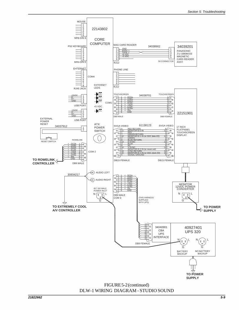
Section 5: Troubleshooting
21822662 5-9
FIGURE 5-2 (continued)DLW-1 WIRING DIAGRAM - STUDIO SOUND
MONITOR12VDC POWERCONVERTER
N L
G
N L
G
N L
G
N L
G
162738495
162738495
< DCDc< DSRc< RXDc> RTSc> TXDc< CTSc> DTRc< RIc
GND
DB9 MALECOM 3 (THIS HARNESS
SUPPLIEDWITH UPS)
DB9 FEMALE
40927401UPS 320
BATTERYBACKUP
NO BATTERYBACKUP
TO POWERSUPPLY
TO POWERSUPPLY
TO EXTREMELY COOLA/V CONTROLLER
AUDIO LEFT
AUDIO RIGHT
30934217
162738495
< DCDb< DSRb< RXDb> RTSb> TXDb< CTSb> DTRb< RIb
GNDTO ROWELINKCONTROLLER DB9 MALE
COM 2
ATXPOWER SWITCH
34037912
ROWELINK
DB15 FEMALE DB15 FEMALE
SVGA VIDEO SVGA VIDEO
SIGNAL GROUNDMONITOR ID 3 IN (or DDC clock I/O)SYNC RETURNMONITOR ID 2 IN (or reserved)V-SYNCNCBLUEH-SYNCBLUE RETURNGREENMONITOR ID 1 IN (or DDC data I/O)GREEN RETURNREDMONITOR ID 0 INRED RETURN6 6
11 111 17 712 122 28 813 133 39 914 144 410 1015 155 5
162738495
< DCDa< DSRa< RXDa> RTSa> TXDa< CTSa> DTRa< RIa
GND
162738495
DB9 MALE DB9 FEMALE
TOUCHSCREEN TOUCHSCREEN34038701
61138123
22151901
17 INCHFLATPANELTOUCHSCREENDISPLAY
123456
123456
12345
GNDRXDd <TXDd >+5 VDC+5 VDC
RJ12
RJ12
PHONE LINE
MAG CARD READER34038902 34039201
PANASONICZU-1890M103MAGNETICCARD READERASSY.50 CONNECTOR
EHTERNET LEDS
COM1
+5 VDC
COM4
123456
123456
123456
1234
78
1234
12
EXTERNALPOWERRESET
RESET SWITCH
USB PORT
USB PORT
+5VDCD-D+GND
+5VDCD-D+GND
RJ45 JACK
EHTERNET
MINI-DIN 6
PS2 KEYBOARD
MINI-DIN 6
MOUSE
22143802
CORECOMPUTER
IEC 320 MALEPOWER INLET
34040901CBAUPS
INTERFACE
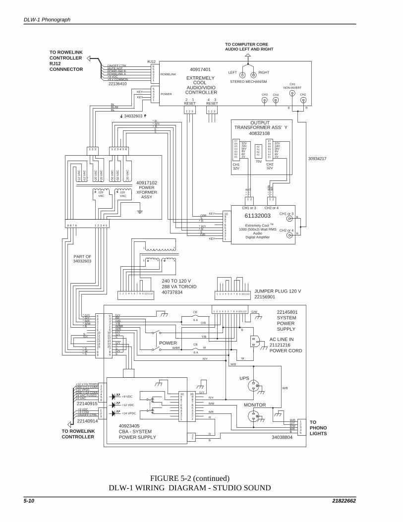
DLW-1 Phonograph
5-10 21822662
FIGURE 5-2 (continued)DLW-1 WIRING DIAGRAM - STUDIO SOUND
E7E6E5E4E3E2E1
E7E6E5E4E3E2E1
A2A1A2A1
OUTPUTTRANSFORMER ASS'Y
40832108
CH132V
CH232V
70V
CH1 or 3 CH2 or 4
1 2 1 2
**
B*
*G
**
B/W
**
BR
TO COMPUTER COREAUDIO LEFT AND RIGHT
RIGHTLEFT
STEREO MECHANISM
40917401
EXTREMELY
AUDIO/VIDIOCONTROLLER
COOL
RESET2 1
RESET4 3
ROWELINK
POWER
654321
54321
1 2 3 1 2 3
ON/OFF CTRLMUTE NOTROWELINK BROWELINK A+9 VDC+9 V COMMON
KEY
KEY
BL
BLBL/W
34032603
1 2 3 1 2 3 4 5 6
RJ12
22136410
TO ROWELINKCONTROLLERRJ12 CONNNECTOR
*R*R/Y*RSS
B R
32V24V16V8V4V2V
32V24V16V8V4V2V
CH3 CH4 CH2
CH1NON-INVERT
30934217
CH1 or 3
CH2 or 4
B
R
10987654321
KEY
KEY
O/WS
*R
*R/Y*RSO/B
61132003
Extremely Cool TM
1000 (500x2) Watt RMSAudio
Digital Amplifier
12 V
AC
12 V
AC
20 V
AC
20 V
AC
50 V
AC
50 V
AC
20 V
AC
120VAC
120VAC
40917102POWER
XFORMERASSY
9 8 7 6 1 2 3 4 5
PART OF34032603
543216101112131415789
543216
101112131415
789
*G/Y*B/Y*B/R*B/W*B
*S*W*S
G/YBRO/BY/BW/BRW/BR/YS/YS
S/YS
S
1 2 3 4 5 6 7 8 9 101112 1 2 3 4 5 6 7 8 9 101112
1 2 3 4 5 6 7 8 9 101112
1 4
5 6 7 8
JUMPER PLUG 120 V22156901
240 TO 120 V288 VA TOROID40737834
POWER
S/YS
6 A
CB
6 A
CBW/BR W
R/Y
O/B
Y/B
W
B
G/W 22145801SYSTEMPOWERSUPPLY
AC LINE IN21121216POWER CORD
W/B
UPS
MONITOR
W/B
BB/RB/WG/YW/B
34038804
12345
10987654321
10987654321
B/R
B/W
R/Y
R
G/Y
21
B
R
40923405CBA - SYSTEMPOWER SUPPLY
+9 VDC
+24 VPDC
+12 VDC
123456
123
+12 V FILTEREDGND (+12 COM)
GND (+24 COM)
+9 VDC+9 COMON/OFF CTRL
22140915
22140914
TO ROWELINKCONTROLLER
TOPHONOLIGHTS
S/YS
+24 VPDC
24 VAC FUSED24 VAC
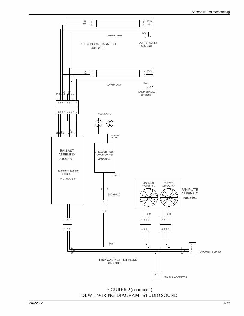
Section 5: Troubleshooting
21822662 5-11
2
1
1
2
1
21
2
W/V
G/Y
BLBLW
VW
W/VV
G/Y
UPPER LAMP
LOWER LAMP
LAMP BRACKETGROUND
LAMP BRACKETGROUNDB
LB
LW W
/V
W/V
G/Y
V V
1 2 3 4 5 6 7 8 9
1 2 3 4 5 6 7 8 9NEON LAMPS
5000 VAC20 mA
12 VDC
1 2
1 2
R B
B/WR
1 2 3
1 2 3
4 3 2 14 3 2 1
4 3 2 1 4 3 2 1
3 2 1
54321
�
TO BILL ACCEPTOR
TO POWER SUPPLY
B
WG/Y
BG/YW
BL
BL
W Y O G/Y
V V
3403910112VDC FAN
3403910112VDC FAN
R RB B
34039910
SHIELDED NEON�POWER SUPPLY
34042901
34039903
�
34043001
BALLAST�ASSEMBLY
(2)F6T5 or (2)F8T5
�
LAMPS
120 V 50/60 HZ
120V CABINET HARNESS
FAN PLATE�ASSEMBLY40928401
120 V DOOR HARNESS�40898710
FIGURE 5-2 (continued)DLW-1 WIRING DIAGRAM - STUDIO SOUND

DLW-1 Phonograph
5-12 21822662
FIGURE 5-3DLW-1 BLOCK DIAGRAM - 2 CHANNEL PREAMP
Mars Series2000 BillAcceptor
RelaySwitched120 VACPower
Credit Pulseand Enable
Credit PulseImonex 2 ChannelCoin Acceptor
Credit Pulseand +12 V
(Optional)Mars 330/212
Nri G-13Coin Controls C120
Micron S5
Electronic CoinAcceptor
Valid IR
IR Recv'r
(Optional)
IR Signals
40875907Control Panel
Reject Sw
Power Sw Volume Control
MDB BillAcceptor
Pulse BillAcceptor
Coin Switches
ElectronicCoinAcceptor
Rowelink(RS232)
Mute40926001Rowelink Controller
Calibrate
Service
Collect
Reject
Power
5 VDC
IRDetector
CRDT STATUS
CRDT RL TX
CC RL TX
CC RL RX
KID RL TX
IR RCV
24 VAC
24 VDC
12 VDC
ON/OFF Control
+9 V, +12 V and +24 VReject Sw

Section 5: Troubleshooting
21822662 5-13
FIGURE 5-3 (continued)DLW-1 BLOCK DIAGRAM - 2 CHANNEL PREAMP
Rowelink
Stereo Input
Mute
Power
Volume Control
CH 1 CH 2
611387012 CHANNEL
PREAMP
61132003EXTREMELY COOL
1000 (500 X 2)WATTS RMS
AUDIODIGITAL AMPLIFIER
Yellow Clip
CH 1 or 3
Reset
Yellow Clip
Red OverloadRed Overload
CH 2 or 4
Output Transformer
ExtensionSpeakers
100 VAC center-tapped, and 20 VAC secondaries
+9 V, +12 V and +24 V
40 VAC center-tapped secondary
This ON/OFF Power Switch disconnects the +12V andrelay switched 120 VAC Power.
ON/OFF CTRL (this signal toggles when the Powerbutton on the optional IR remote is pushed).
Ethernet
RX
Link
TX
Audio Leftand Right
COM 2Rowelink
SVGAVideo
COM 1
22143802CORE
COMPUTER
Hard Drive Green
Hard Drive Yellow
Keyboard
Mouse
USB
PhoneLine
COM 4
+5 V
NotUsed
COM 3
ATX Power Switch
40917102POWER TRANSFORMER
ASSEMBLYTransforms 120 VACprimary to secondary's forthe 2 channel preamp, andDC voltage supplies.
ROUTER
(Located outside of Phonograph)
22160801 or 2215190115 or 17 inch
SVGA TFT-LCDTouchscreen Monitor
MonitorPowerSupply
RelaySwitched120 VACPower
RelaySwitched120 VACPower120 VAC Lamps
NeonLamps
Neon PowerSupply
Relay Switched12 V Power
40927401 UPSPower ON
ON/OFF
Wiring Fault
120 VACBatteryBacked-upPower
Always ON120 VACPower
MagneticCard
Reader
34039201
External ATX Power/Reset Switch Locatedon Back on Starlink
22145801SYSTEM POWER
SUPPLYSupplies power to allsystem componentsPower Switch - disconnectspower from all componentsexcept the UPS and the CoreComputer
Power
+12 V +24 V+9 V
120 VACLine
Input
RelaySwitched12 VPowerRelaySwitched120 VACPower
A DPDT relay supplies 120 VAC power tothe Touchscreen Monitor, FluorescentLamps and Bill Acceptor and 12 V powerto the neon power supply.A high ON/OFF CTRL signal de-energizesthe relay to disconnect the 120 VAC, 12 Vand 24 V power.

DLW-1 Phonograph
5-14 21822662
FIGURE 5-4DLW-1 WIRING DIAGRAM - 2 CHANNEL PREAMP
123
G/YW
B
16 117 218 319 420 521 6
22 723 824 925 1026 1127 1228 1329 1430 15
Mars AC2411-U7EBill Acceptor
BL GROUND
O +5 VDCGY CREDIT/INTERRUPTR ESCROW/SENDBR /ENABLE
22135602
120 VAC
1 2 3 4 5 6 7 8 910 1 2 3 4 5 6DUAL ROW
1 2 3P17 P18
MDB ACCEPTOR COUNTERBILL ACCEPTOR
TO POWERSUPPLY
123
+9 VDC+9 V COMMONON/OFF CTRL
123456
+12V FILTERED+12V COMMON+24 VP DC+24V COMMON24 VAC FUSED24 VAC
22140914
22140915
P14
P19
P23
P16
P15 P3
12
2 1 1 2
123456
POWER IN
POWER IN
POWER
REJECT AMP MUTE
ROWELINKX 5P5,6,7,8,9
P11
IR DETECTOR
ROWELINK
DISCRETE WIRE
TB1
123456
1234
S1 COLLECT
S2 POWER
S3 CALIBRATE
S4 REJECT
S5 SERVICE 123456
123456
123456
78
789
10
COIN A COMCOIN A SIG
LED A ANODELED B CATHODECOIN B SIGCOIN B COM
12345678
12345678
123456789
10
+12 COM+12 VDCCOIN 5COIN 6NOT USEDINHIBIT ALL COINSCOIN 1COIN 2COIN 3COIN 4
P20
P2122140913
22132223
IMONEX2 Channel
COIN ACCEPTOR
70089308
MARS 330/212
NRI G-13
COINCONTROLSC120
MICROCOIN S5& INTERFACEBOARD
ELECTRONICCOINACCEPTOR
DUAL ROWDUAL ROW
SERVICEREJECTCALIBRATEPOWERCOLLECTGROUND
SWITCHES
P12DB9 FEMALE
1 > DCDb6 > DSRb2 > RXDb7 < RTSb3 < TXDb8 > CTSb4 < DTRb9 > RIb5 GND
RS232 ROWELINK
POWER OUT
STATUS
KID RL TX
IR RCV
CRDT RL TX
1234
CC RL TX
CC RL RX
+5V DC
CONTROLLER LED'S
+12V DC
+24 V DC
24V AC
+12 COM+12 VDC
+9 VDC+9 V COM
+9 VDC+9 V COMMONROWELINK AROWELINK B
COINSWITCHES
COINACCEPTOR
ROWELINK CONTROLLER40926001
34022310
34038701
TO COMPUTERCORE
REJECTVOLUMECONTROL
POWERSWITCH
40875907
TO 2 CHANNELPREAMP
TO POWER SUPPLY
CONTROL PANEL
O/B-1
*B
L
*B
/W
W/V
O
B/W
BBW V
BR
34037910
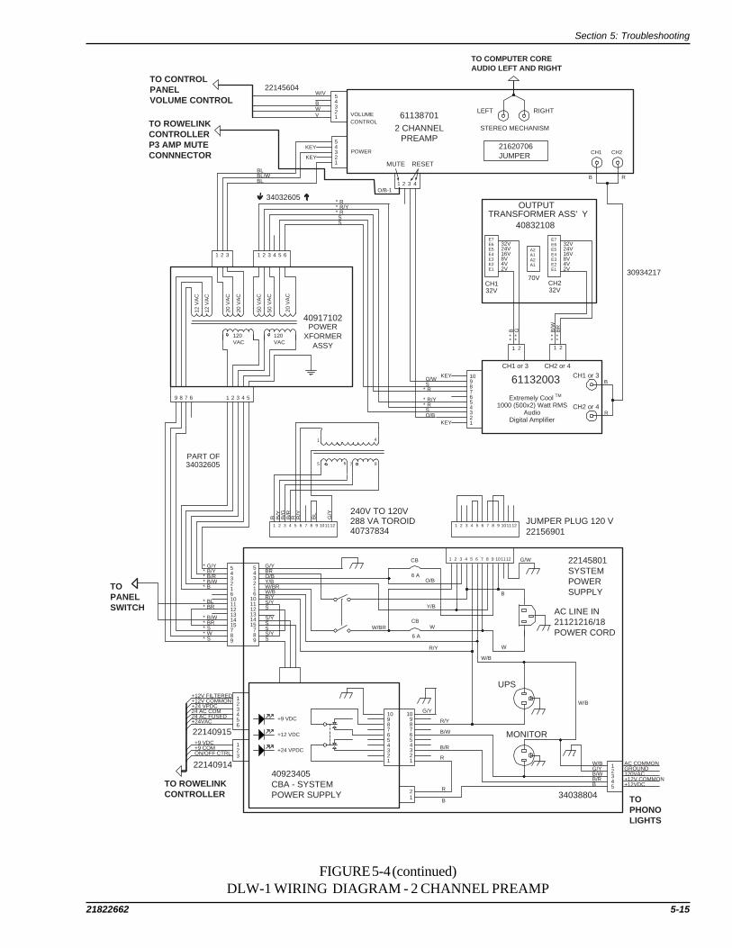
Section 5: Troubleshooting
21822662 5-15
FIGURE 5-4 (continued)DLW-1 WIRING DIAGRAM - 2 CHANNEL PREAMP
E7E6E5E4E3E2E1
E7E6E5E4E3E2E1
A2A1A2A1
OUTPUTTRANSFORMER ASS'Y
40832108
CH132V
CH232V
70V
CH1 or 3 CH2 or 4
1 2 1 2
**
B*
*G
**
B/W
**
BR
TO COMPUTER COREAUDIO LEFT AND RIGHT
RIGHTLEFT
STEREO MECHANISM2 CHANNEL
MUTE
VOLUME
POWER
54321
1 2 3
KEY
KEY
BL
BLBL/W
34032605
1 2 3 1 2 3 4 5 6
TO ROWELINKCONTROLLERP3 AMP MUTE CONNNECTOR
*R*R/Y*RSS
B R
32V24V16V8V4V2V
32V24V16V8V4V2V
CH2CH1
30934217
CH1 or 3
CH2 or 4
B
R
10987654321
KEY
KEY
O/WS
*R
*R/Y*RSO/B
61132003
Extremely Cool TM
1000 (500x2) Watt RMSAudio
Digital Amplifier
12 V
AC
12 V
AC
20 V
AC
20 V
AC
50 V
AC
50 V
AC
20 V
AC
120VAC
120VAC
40917102POWER
XFORMERASSY
9 8 7 6 1 2 3 4 5
PART OF34032605
543216101112131415789
543216
101112131415
789
*G/Y*B/Y*B/R*B/W*B
*S*W*S
G/YBRO/BY/BW/BRW/BR/YS/YS
S/YS
S
1 2 3 4 5 6 7 8 9 101112 1 2 3 4 5 6 7 8 9 101112
1 2 3 4 5 6 7 8 9 101112
1 4
5 6 7 8
JUMPER PLUG 120 V22156901
288 VA TOROID
S/YS
6 A
CB
6 A
CBW/BR W
R/Y
O/B
Y/B
W
B
G/W 22145801SYSTEMPOWERSUPPLY
AC LINE IN21121216/18POWER CORD
W/B
UPS
MONITOR
W/B
BB/RB/WG/YW/B
34038804
12345
10987654321
10987654321
B/R
B/W
R/Y
R
G/Y
21
B
R
40923405CBA - SYSTEMPOWER SUPPLY
+9 VDC
+24 VPDC
+12 VDC
123456
123
24 AC COM24 AC FUSED
+24 VPDC
+9 VDC+9 COMON/OFF CTRL
22140915
22140914
TO ROWELINKCONTROLLER TO
PHONOLIGHTS
+12V FILTERED+12V COMMON
+24VAC
AC COMMONGROUND120VAC+12V COMMON+12VDC
240V TO 120V
40737834
B B/Y
B/G
B/R
R R/Y
BL
G/Y
4
PREAMP
61138701CONTROL
54321
TO CONTROLPANEL VOLUME CONTROL
22145604W/V
BWV
O/B-1
21620706JUMPER
*BL*BR
*B/W*BR
TO PANELSWITCH
RESET

DLW-1 Phonograph
5-16 21822662
FIGURE 5-4 (continued)DLW-1 WIRING DIAGRAM - 2 CHANNEL PREAMP
MONITOR12VDC POWERCONVERTER
G G
G G
162738495
162738495
< DCDc< DSRc< RXDc> RTSc> TXDc< CTSc> DTRc< RIc
GND
DB9 MALECOM 3 (THIS HARNESS
SUPPLIEDWITH UPS)
DB9 FEMALE
40927401UPS 320
BATTERYBACKUP
NO BATTERYBACKUP
TO POWERSUPPLY
TO POWERSUPPLY
TO 2 CHANNELPREAMP
AUDIO LEFT
AUDIO RIGHT
30934217
162738495
< DCDb< DSRb< RXDb> RTSb> TXDb< CTSb> DTRb< RIb
GNDTO ROWELINKCONTROLLER DB9 MALE
COM 2
ATXPOWER SWITCH
34037912
ROWELINK
DB15 FEMALE DB15 FEMALE
SVGA VIDEO SVGA VIDEO
SIGNAL GROUNDMONITOR ID 3 IN (or DDC clock I/O)SYNC RETURNMONITOR ID 2 IN (or reserved)V-SYNCNCBLUEH-SYNCBLUE RETURNGREENMONITOR ID 1 IN (or DDC data I/O)GREEN RETURNREDMONITOR ID 0 INRED RETURN6 6
11 111 17 712 122 28 813 133 39 914 144 410 1015 155 5
162738495
< DCDa< DSRa< RXDa> RTSa> TXDa< CTSa> DTRa< RIa
GND
162738495
DB9 MALE DB9 FEMALE
TOUCHSCREEN TOUCHSCREEN34038701
61138123
2215190117 INCH
22160801
OR
15 INCH
FLATPANELTOUCHSCREENDISPLAY
123456
123456
12345
GNDRXDd <TXDd >+5 VDC+5 VDC
RJ12
RJ12
PHONE LINE
MAG CARD READER34038902 34039201
PANASONICZU-1890M103MAGNETICCARD READERASSY.50 CONNECTOR
EHTERNET LEDS
COM1
+5 VDC
COM4
123456
123456
123456
1234
78
1234
12
EXTERNALPOWERRESET
RESET SWITCH
USB PORT
USB PORT
+5VDCD-D+GND
+5VDCD-D+GND
RJ45 JACK
EHTERNET
MINI-DIN 6
PS2 KEYBOARD
MINI-DIN 6
MOUSE
22143802
CORECOMPUTER
IEC 320 MALEPOWER INLET
34040901CBAUPS
INTERFACE

Section 5: Troubleshooting
21822662 5-17
FIGURE 5-4 (continued)DLW-1 WIRING DIAGRAM - 2 CHANNEL PREAMP
2
1
1
2
1
21
2
W/V
G/Y
BLBLW
VW
W/VV
G/Y
UPPER LAMP
LOWER LAMP
LAMP BRACKETGROUND
LAMP BRACKETGROUNDB
LB
LW W
/V
W/V
G/Y
V V
1 2 3 4 5 6 7 8 9
1 2 3 4 5 6 7 8 9NEON LAMPS
5000 VAC20 mA
12 VDC
1 2
1 2
R B
B/WR
1 2 3
1 2 3
4 3 2 14 3 2 1
4 3 2 1 4 3 2 1
3 2 1
54321
TO BILL ACCEPTOR
TO POWER SUPPLY
B
WG/Y
BG/YW
BL
BL
W Y O G/Y
V V
3403910112VDC FAN
3403910112VDC FAN
R RB B
34039910
SHIELDED NEONPOWER SUPPLY
34042901
34039903
34043001
BALLASTASSEMBLY
(2)F6T5 or (2)F8T5
LAMPS
120 V 50/60 HZ
120V CABINET HARNESS
FAN PLATEASSEMBLY40928401
120 V DOOR HARNESS40898710

DLW-1 Phonograph
5-18 21822662
TROUBLESHOOTING CHARTS
The best way to isolate a problem is to determine its cause. The following charts should help to narrow downwhich module is failing and whether it can be fixed or needs to be replaced.
Start with finding the “Trouble” column that relates the closest to the problem you are experiencing and thenmatch it to the closest “Symptom”. There can be many “Probable Causes” listed for each Symptom. TheProbable Causes are listed in increasing order of probability.
Trouble Symptom Probable causeApplication does not boot up At the first boot up screen, 1. The hard drive tray is not key-locked
“Detecting IDE Primary Master” into placereports “None” 2. The hard drive tray in the CC box
has come loose and needs to be re-seated
3. There is no tray in the CC box4. There is no hard drive in the tray5. The tray was not inserted correctly6. The plugs in the tray are not com
pletely seated in the hard drive7. The data cable or power plug (CC
box internal) has come loose from themain board or hard drive bay
The boot up process stops at 1. The hard drive tray in the CC box has“DISK BOOT FAILURE, INSERT come loose and needs to be re-seatedSYSTEM DISK AND PRESS 2. There is no tray in the CC boxENTER” 3. There is no hard drive in the tray
4. The hard drive tray is not key- lockedinto place
5. The tray was not inserted correctly6. The plugs in the tray are not completely
seated in the hard drive7. The data cable or power plug (CC
box internal ) has come loose fromthe main board or hard drive bay
8. The hard drive is dead
At the first boot up screen, 1. The CC’ s BIOS needs to be updated“Detecting IDE Primary Master”hangs at “[Press F4 to continue]”
The tray is stuck The tray will not come out of 1. The tray was not un-locked.the drive bay 2. The handle was not lifted up 90
degrees before trying to be pulled out3. Tray is jammed4. Acceptor bay is broken

Section 5: Troubleshooting
21822662 5-19
Trouble Symptom Probable CauseJukebox will not operate When plugged into a standard 1. The Power button was pressed onwhen powered ON wall outlet the florescent lights Volume Control Unit or IR Remote.
fail to light 2. The plug is not completely inserted intothe outlet.
3. Wall circuit is not hot.4. All fluorescent lights are burned out.
Fluorescent lights come on, but 1. The Computer ATX power/resetthe application will not boot button was not pressed in
2. UPS is OFF-(green LED is not lit)3. UPS is defective or unplugged4. The monitor or its power supply is
defective or unplugged.
The TFT-LCD monitor The computer fan is on, and all 1. The power plug, video cable, ordoes not work systems LED’s are normal monitor power supply wiring is not
seated completely.2. The monitor power supply is defec-
tive.3. The monitor is dead.
The touchscreen does not The application boots up, but 1. The serial cable is not seatedwork the touch screen does not respond completely at the monitor or at the
to touch CC box2. The touch screen is dead.
The credit card acceptor Nothing happens when a card 1. There is no power at the creditdoes not work is inserted card acceptor
2. The card was not inserted all the way3. The card was inserted with the
stripe facing the wrong way4. The application is not running5. The cable is not plugged in securely
to the outside of the CC box6. The credit card acceptor is dead
There is no power at the credit 1. The cable is damaged at the acceptorcard acceptor 2. The connection is loose at the CC
box

DLW-1 Phonograph
5-20 21822662
Trouble Symptom Probable CauseThe bill acceptor does not The bill acceptor will not 1. The cash box is fullwork accept a bill 2. The cash box was not re-installed on
bill acceptor correctly3. There is a jammed bill in the device4. The plugs are not inserted securely at
the acceptor5. The acceptor is dead
The green lights at the bill 1. The cable is damaged at the acceptoracceptor lip are not flashing 2. The bill acceptor is dead
The touch screen will not Nothing happens after pressing 1. The wrong button was pushedcalibrate the calibration button 2. Rowelink is not running or the
Rowelink Controller is defective
The calibration program runs, 1. The serial cable plug is not fullybut will not respond to touch seated at the monitor or at the CC box
2. The touch screen is dead
No music from jukebox No sound from jukebox, 1. Volume control is turned all the wayalthough the application reports down“Now Playing…a New song” 2. Volume control is broken
3. Audio/Video controller or 2 channelpreamp is continually muting the song
4. Sound plug is disconnected or loosefrom the CC box
5. The amplifier was overloaded andshutdown
No sound from jukebox and 1. There are no more credits availablethe application doesn’t appear for playto be playing the song selected 2. Reject song was activated
Machine is locked up Bill acceptor is taking money 1. CC is locked up, press the externalduring normal runtime but touch screen is not responsive ATX power/reset button. (see figure
1-1) if CC does not boot up, do acomplete Power-up
Venue Network There is no designated phone 1. The inside wiring installation ap-line installed in the Venue pointment was not scheduled
2. The inside wiring installation hasnot occurred
3. The line was not installed in thepre-selected location
4. The line (jack) was not labeled bythe technician

Section 5: Troubleshooting
21822662 5-21
Trouble Symptom Probable Cause3. The line was not installed in the
pre-selected location4. The line (jack) was not labeled by
the technician
Router does not work When the power button is 1. The AC power plug is not fullydepressed nothing happens inserted in the receptacle on the back
of the router2. The wall plug is not “hot”3. The button is not pushed all the way in
When the power button is pressed, 1. The power button was not fullymany lights flash on and then all depressed to catch and remaingo out in the ON position
The “Link/Receive #” light, in the 1. Ethernet port #1 is not suppose tofront of the router, does not light up be usedwhen an Ethernet cable is plugged 2. The Ethernet port is deadin the respective # 3. The jukebox is not powered on
4. The cable is loose at the CC box inthe jukebox
The “Download Now” Neither feature has ever been 1. There is no Ethernet cable connectionfeature and/or the available in the venue between the router and the jukebox“Buy CD” feature 2. The Ethernet cable is not fully seated
in the port on the CC box or in theback of the router
3. The connection is loose between theinstalled line and the router
4. The cable is bad5. The router is not the right one for the
venue it has been placed in6. The internet line is down
ONLY “Buy CD” is available 1. The router is not configured correctly
The features were available, but 1. The connection has become looseno longer available between the router and the jukebox
2. The connection has become loosebetween the installed line (jack ) andthe router
3. All the lights are ON, on the front ofthe router
4. The router was shut off or lost power5. The internet service provider (isp) is
down6. The Ecast music Database server is
down

DLW-1 Phonograph
5-22 21822662
This page intentionally left blank
Section 6: Network
21822662 6-1
Section 6: Network
INTRODUCTION
In order to bring the DLW-1 Network and the Internet to eachvenue, a separate phone line must be installed at each site.Depending on availability and the geographic location of thevenue, the line will be a standard phone line providing dial-upInternet service, or digital cable, wireless broadband, or symmet-ric Digital Subscriber Line (DSL) providing faster Internet ser-vice. Either way, the router installation will be the same. Whetherthe venue will use the SDSL or dial-up technology depends onthe venue’s geographic location, and it will be ordered by Ecast.The final line installation procedure will be slightly different foreach technology, as described below. Either way, prior to lineinstallation, the Operator will need to coordinate with the venueto select a location for installation of the designated phone line.The installation for the router will be the same for either technol-ogy.

DLW-1 Phonograph
6-2 21822662
WHERE TO INSTALL THE DESIGNATED LINE AND ROUTERFirst and foremost, Ecast wants to make the installation process for the Operator as easy and smooth as possible.We realize that the DLW-1 System requires another piece of equipment, the router, and more wired connectionsthan previous Jukeboxes, but it doesn’t have to be more work than need be. Security is the number one concernwith placement of the designated phone line and router.
NOTE:The “line” will look like a standard wall jack in the venue, no matter which technology isemployed.
The line can be installed in any of the following:• an indoor telephone closet (preferably on the same floor as the Jukebox)• an indoor utility closet (preferably on the same floor as the Jukebox)• closet or office where other sound equipment is located• behind the bar• next to a utility switch box in a back room
Do Not install the line:• behind the old jukebox or behind the DLW-1 Jukebox• in a place where it is extremely difficult to run a cable from• in a high traffic area where the telephone cable could get pulled out
The router can be installed:• next to the designated line• next to other sound equipment in a closet, office or behind the bar• any location close to and between the Jukebox and Countertop (you may have to run one long cable from
the designated line to the router)
Do Not install the router:• in the DLW-1 Jukebox• where customers have access to it• in an area where electronic components could be damaged• far from and with physical obstacles between the DLW-1 units (on another floor, through doorways with
closed doors, etc.)• far away from a standard wall power plug
NOTE:Ecast is happy to provide possible placement locations in the venue for the DLW-1 router. Thebest way we can offer suggestions is by viewing a sketch of the location’s floor plan. Make sureto label each room, for example, dining, bar, pool tables, kitchen, private room, etc.

Section 6: Network
21822662 6-3
INSTALLING THE DESIGNATED LINE
DSL:If the venue is in an area where DSL is available, Ecast will order the installation of this technology. The time linefor getting DSL installed in a venue is slightly longer than dial-up, but the technology is preferable as it provides afaster Internet connection.
The following are the steps for installing DSL in the venue.
Step 1: The venue will receive the router box via mail from a third party or the installer.
Step 2: Ecast will notify when the router has been shipped and the venue is ready for the final line installation bycalling the Operator or sending an instruction sheet specific to the venue via mail, fax, or e-mail.
Step 3: The final line installation date and time can be set up per the Operator’s, DSL Providers’s, and venue’sconvenience. Ecast encourages the Operator to be present at the time of installation to direct the technicianwhere to install the line. If this is not possible, the selection can be made prior to the installation as longas someone at the venue can direct the technician.
Step 4: The router should also be installed at this time (see INSTALLING THE ROUTER below).
Step 5: Call Ecast and inform that the line is in.
Dial-Up:Dial-up is the default option that is available to every venue if DSL isn’t. The Internet connection is brought to thebar via a standard telephone line. Ecast will order the dial-up Internet through our partner, Global Crossing, but theline will be installed by a local telephone carrier.
NOTE:Dial-up line installation differs from DSL line installation in the procedure. Be careful not to confusethe two if your venues use both technologies. Also, the router will be sent to the Operator asopposed to the venue.
The following are the steps for installing the Dial-up line in the venue.
Step 1: The router box will be sent directly to the Operator via mail from Ecast.
Step 2: Ecast will notify when the router has been shipped and the venue is ready for the final line installation bycalling the Operator or sending an instruction sheet specific to the venue via mail, fax, or e-mail.
Step 3: The final line installation date and time can be set up per the Operator’s, local telephone carrier’s, andvenue’s convenience. Ecast encourages the Operator to be present at the time of installation to direct thetechnician where to install the line. If this is not possible, selection can be made prior to the installation aslong as someone at the venue can direct the technician.
Step 4: The router should also be installed at this time (see INSTALLING THE ROUTER below).
Step 5: Call Ecast and inform that the line is in.

DLW-1 Phonograph
6-4 21822662
INSTALLING THE ROUTER
IntroductionThe DLW-1 Router provides two major functions for the DLW-1 System. It is the connecting hub for theDLW-1Jukebox in the venue and delivers the Internet from the outside world. The router box is the smart-translation toolthat dials into the designated phone line and delivers the Internet to the Units in the bar (see Figure 6-1). Theconnection between the router to the designated phone line and to jukebox will be the same for both types ofInternet technology (Dial-up or DSL).
DescriptionThe Dial-up and DSL routers look exactly the same from the outside and provide the same functions to the user,but at different speeds. The only external difference between the Dial-up and the DSL router is the model number(see Table 1A).
Internet Access Router Model Number1 Dial-up Netopia 2020 2DSL Netopia 7100-C
Table 1A
CAUTIONThere is a major difference between the two routers’ internal hardware and how they areconfigured. Due to these internal differences, it is very important that the correct router is installedin the venue that it is configured for. (Routers are non-transferrable!) Also, the Dial-up Routerwill be sent directly to the Operator and the DSL Router will be sent directly to the venue whereit will be installed.
NOTE:If the router is removed from the box it is shipped in, it can also be identified by the manufacturerserial number located on the underside of the router. Cross check this serial number with EcastTechnical Support.
WARNINGThe router must have 24-hour AC power. For all the same reasons the jukebox must have alwayson power, the jukebox would be useless without the router.
DSL LINEPOWER CORDETHERNET CABLE�
FROM JUKEBOX
LINE 1
FIGURE 6-1

Section 6: Network
21822662 6-5
The following steps describe how to install the router in the venue:
Step 1: Select a LocationRegardless of where the designated telephone jack was installed, the router box must be kept away fromtampering, accidental shut off or from tech-savvy customers who could potentially steal Internet servicefrom the venue (and operator). Please see “Where to Install the Designated Line and Router” for moresuggestions. Contact Ecast’s technical support if you have any questions about the placement location.
Step 2: Mount or Place the RouterThe best place to install the router is on a shelf or a ledge. If this is not possible, the box can be mountedto a wall. The underside of the box has two holes about 4-3/4” apart. Be sure that you can view the frontof the box (non-plug side) where the signal lights are located.
Step 3: ConnectionsConnect a single phone line cable from the router port labeled “Line 1” (see Figure 6-2) to the designatedphone jack. If the provided cable is not long enough, you can purchase a longer one or make your own(see “Standard Phone Cable Pin Out and Sources”). Next, connect the 9-pin AC power adapter to theback of the router labeled “Power”. Connect the other end to any standard wall plug or extension cord.
Step 4: Power on the RouterOn the front of the router, press the Power button all the way in until it catches and remains depressed.Different green and red lights will flash on the router, but should settle to 2 green lights with the labels“WAN1: Ready” and “WAN 2: Channel 1”. Assuming the line is good, the router should automaticallybe connected to the Internet.
Step 5: Leave the Router OnOnce the inside line and router are installed in the location, Ecast can test the line remotely and make surethe line is good. If there are any problems, Ecast will work with the Operator and the Internet providerto produce a swift solution. If the line is working properly, the Operator will be informed and the venuewill be ready for unit installation.
DSL LINEPOWER CORDETHERNET CABLE�
FROM JUKEBOX
LINE 1
FIGURE 6-2

DLW-1 Phonograph
6-6 21822662
STANDARD PHONE CABLE PIN OUT & SOURCES
A longer phone cable will be needed if the Router is placed at a greater distance than the provided cable. Thiscable has 2 twisted pairs with pin 1 to pin 4, pin 2 to pin 3, pin 3 to pin 2, and pin 4 to pin 1. It is availablein different lengths, or parts to make your own custom length can be purchased at Radio Shack, Digi-Key, or othersources.

Section 7: Using the DLW-1
21822662 7-1
Section 7: Using the DLW-1
INTRODUCTION
The following is a reference guide for the Operator to navigate theuser interface on the DLW-1 Jukebox. There are a couplereasons why it is important that the Operator feels comfortablewith all of the user interface features. First, the Operator needs toknow how to answer questions on how to use the jukebox forvenue workers or patrons in the field. Second, the Operatorneeds to know what a normal run time interface looks like inorder to troubleshoot when the user interface or part of theinterface is down.

DLW-1 Phonograph
7-2 21822662
OPERATING THE DLW-1 JUKEBOX
Use this reference guide to navigate the DLW-1 Jukebox
APPROACHING THE JUKEBOX
Attract loop:
This moving image file consists of advertisements and graphics and appears when no one has touched the systemfor a few minutes. Simply touch the screen to begin using the system. The attract loop will automatically disappear.
Getting started:
Touch any part of the screen to begin viewing album covers.
Attract Loop
Jukebox User Interface
Paying to use the System:Insert $1.00, $5.00, or a credit card ($5 and $10 choices) to receive credits. The $/credit ratio appears on thescreen. Total credits earned based on money inserted will appear in the lower left-hand corner.

Section 7: Using the DLW-1
21822662 7-3
USING THE SYSTEM
Selecting Local Music:
Browse through album covers on the local jukebox by pressing the arrow keys below the 4 album covers thatappear on the right hand side of the screen. To view the songs on an album, touch the album and the songlist will appear to the left of the 4 album covers. Scroll down or up with the double arrows to view all songson the album. Make a song selection by touching the song # or title. The song will be selected as long asthere is at least 1 credit under “Credits Remaining” in the bottom left-hand corner.
Search All Music on the Ecast Network:
Press the “Search All Music” button that appears below the alphabet scroll arrows on the right hand side ofthe screen. Album covers or the “Download Now” icon will appear to the left of the artist’s names and theiralbums available. (The “Download Now” icon signifies an album not on the local jukebox but can beplayed for an extra credit per song.) From there you can search by song, artist, album, or genre. Touch in themiddle of the tabs that appear on the top of the screen to modify your search. As soon as one letter hasbeen typed into the keyboard, the search will jump through the albums or artists to narrow the search.
Selecting Music From the Internet:
If the song you want to play is on an album with the “Download Now” icon, then the song will have to beaccessed via the Internet. The song selection process is the same as for local music. Scroll down or up withthe double arrows to view all songs on the album. Make a song selection by touching the title. The song willbe selected as long as there is at least 2 credits under “Credits Remaining” in the bottom left-hand corner. Adialogue box will inform that the song selected is not on the DLW-1 and will have to be downloaded. Thenext dialogue box will prompt to “Begin” the download for an extra credit or to “Cancel” the selection.
Buy CD button:
Patrons will see “Buy CD” buttons in a variety of places within the screen. Anytime a song is chosen and sitsin the queue on the left hand side of the screen, you will see a “Buy CD” button. In addition, patrons will seea “Buy CD” button next to the now playing song in the upper right-hand corner. If a patron touches thatbutton, an amazon.com web page will appear displaying the exact album they would like to buy.
Search All Music Screen

DLW-1 Phonograph
7-4 21822662
OPERATING THE JUKEBOX – SHORT SHEET
Jukebox Music Station
To select an Album —
Two Ways:1. Scroll through the groupings of 4 album covers using the scroll bar at the bottom of the screen.
Touch the album and the song list will appear on the screen.2. Touch the Search All Music button at the bottom of the screen. Search by album and touch
the name of the album to view it’s song list.
To select a Song —
After selecting an album, scroll through the song list using the arrow keysTOUCH the NAME of the SONG you want to select
To purchase an Album —
1. Touch the “Buy CD” button next to the album or “Current Song Playing” indicator2. From the Amazon.com Interface, Touch the “Add to Shopping Cart”3. Touch the “Proceed to Checkout Button”4. Use the virtual Keyboard to enter information as requested

Section 8: Extranet
21822662 8-1
Section 8: Extranet
INTRODUCTION
The Extranet is an Internet that only a company’s employees andtheir business partners can access. This private Internet is ac-cessed by a given username and password. Only information thatpertains to the user logged in can be viewed and accessed by thatuser.

DLW-1 Phonograph
8-2 21822662
GENERAL QUESTIONS FOR INTERNET BEGINNERS
Clicking:
To click, press and immediately release the left button on your mouse.
Pull-down menus:
Pull-down menus give you access to a list without taking up a lot of space. A pull-down menu is a horizontal,rectangular box with an arrow on the right pointing down. The box shows you the menu’s option that is currentlyin effect. Click the box and a list of all available options will appear. Each option listed will perform a differenttask. Just click the option you want and the screen will automatically change to reflect your choice.
Using the “Go” button:
Clicking the “Go” button processes your request or sends you to a task’s next step.
How do I return to the previous pages?:
Click the square labeled “Back” on the upper-left corner of your computer screen. The “Back” button is part ofyour Internet browser.
NOTE:The Ecast Extranet is a secure site. Once a user leaves the Extranet and an other web site isentered, the user must log on again to the Extranet. Do not expect to re-enter the Extranet byclicking the Back button to re-enter the site.
Downloading :
When you download albums, you are transferring albums from Ecast’s vast database to your DLW-1 System’shard drive.
Printing:
Printing a page from the Extranet is just like printing a word processing document. You can either click the squarelabeled “Print” on the toolbar along the top of the screen, or click the word “File” on the upper-left corner of yourscreen and choose “print .” When a new window appears, just click “OK” at the bottom of the window to beginprinting.

Section 8: Extranet
21822662 8-3
GENERAL QUESTIONS FOR EVERYONE
How do I access the Extranet?
Bring up any internet browser, for example: Netscape, Internet Explorer, or AOL. Type in the following address:www.ecastcentral.com
My username and password:
Your username identifies you to the DLW-1 Management System. Your password tells the system that the personlogging in with your username is really you.
How do I get a username and password?
Upon the return and approval of the Operator Contract with Ecast, a username and password will be randomlygenerated along with the set up of the venues that the units will be going into. Once the venue database is created,you will be informed of your password.
How do I change my username or password?
Email Ecast at [email protected] or call toll free (877) 451-1537. Be sure to include your name,phone number, company name, city, and state with your request.
What if I forget my username or password?
Email Ecast at [email protected] or call toll free (877) 451-1537. Be sure to include your name,phone number, company name, city, and state with your request.
Who can view my account?
Only you and Ecast can view your account unless you share your username and password with anyone else.
How do I get to each section’s home page?
The names of each section are listed across the top of your computer screen below the “Extranet: DLW-1 unitmanagement system” banner. Click one of the names to get to that sections home page. There are six sections:Revenue Reports, Usage Reports, Music Reports, System Reports, Update Music, and Edit Profile.
If you have questions regarding the extranet reports you may contact Ecast Customer Service [email protected] or call toll free (877) 451-1537.

DLW-1 Phonograph
8-4 21822662
REVENUE REPORTSBy clicking on a venue name you can view details of the revenue generated and select options to generate reports forspecific time periods.
USAGE REPORTSBy clicking on a venue name you can view top songs, albums, and games. Options include list length (top 10 or top40) and time period.
MUSIC REPORTSThe music reports screen will allow you to select from numerous options to view the most popular music bygeographic location, album, artist, genre, time period, etc.
SYSTEM REPORTSWhat are System Reports?
System Reports are Ecast’s way of monitoring your units for you. When a unit is experiencing technical problems,it will not respond to a system check and Ecast will post this on the DLW-1 Management System for your review.
How often are system reports carried out?
Every day after the venue has closed.
How to read system reports
Click System Reports at the top of the screen to get to the sections home page. A list of locations with either a checkmark or an “x” to the right of each name will appear. The check mark means all units at that venue are OK. The“x” means a unit at that location isn’t working properly.
For a detailed system report on each location, click one of the venue names on the System Reports home page. Alist of units at that venue will appear with either a check mark or a circle next to each unit. A check mark indicatesthat the unit is OK. A circle means the unit did not supply a report on the last system check and may not be workingproperly.
Can I find out what’s wrong with a unit that is not working properly?
Not currently. Soon the System Reports section will tell you what each problem is and when it occurred.
What to do if a unit isn’t working
First, contact the location manager. Maybe the unit was accidentally unplugged or there is some other simpleexplanation. If the venue manager can’t fix the problem, contact the distributor.

Section 8: Extranet
21822662 8-5
UPDATE MUSIC
Adding, deleting albums
Use either the Auto Suggest, Music Advisor, or Manual Select/Manual Remove features described below.
Auto Suggest
In this section, Ecast recommends what albums to download to or remove from a particular location’s DLW-1System based on the location’s profile; “most-popular” lists; new artists, albums, or songs; and music labelsuggestions.
To add music, click one of the venues listed in the Update Music home page, then click the “Auto Suggest” buttonin the “Add Music” section. A list of albums will appear. Click the box next to each album you want to add thismonth, keeping in mind how many albums you can download (see maximum downloads per month questions/answers below). Checks will appear in those boxes. You can erase a check by clicking the box again. When you’resatisfied with your choices, click “go” at the bottom of the screen. Ecast will process your request overnight.
To remove music, click one of the venues listed in the Update Music home page, then click the “Auto Suggest” buttonin the “Delete Music” section. A list of albums will appear. Click the box next to each album you want to delete.A check should appear in a clicked box. You can erase a check by clicking the box again. When you’re satisfiedwith your choices, click “go” at the bottom of the screen. Your choices will be deleted by the next day.
Music Advisor
This section allows you to choose what albums to add to a DLW-1 System based on their popularity. You can basethe search on popularity by region, Ecast’s top 40, newest music, what has been requested on your machine, andthe hottest music in pop, hip-hop, country, or rock.
Follow the same process as you would using “Auto Suggest” (see above). Just click one of the venues listed in theUpdate Music home page, then click the “Music Advisor” button. A list of albums will appear. Click the box nextto each album you want to add this month, keeping in mind how many albums you can download this month (seemaximum download questions/answers below). Checks will appear in those boxes. You can erase a check byclicking the box again. When you’re satisfied with your choices, click “go” at the bottom of the screen. This willsend your download requests to Ecast, which will process them overnight.
If you want to change the factors on which to base your search, such as popularity by region, Ecast top 40, what’sbeen requested at that venue, etc., click one of the venues listed on the Update Music home page, then click the“Music Advisor” button. Click the pull-down menu labeled “Show list according to:” at the top of the page. Clickthe option you want and the list of albums given will automatically change to reflect the new choice.
Continued on next page

DLW-1 Phonograph
8-6 21822662
Manual Select/Remove
This section enables you to search for a specific album, artist, song, or genre, and then choose from the resulting listwhat albums you want to add or delete.
To add music, click one of the venues listed on the Update Music home page, then click the “Manual Select” buttonin the “Add Music” section. In the box below the “Search” title, type one or two keywords to search for. Belowthe box, click the circle to the left of either “album,” “artist,” “song,” or “genre”. Then click the “Search” button tothe right of the box. A list of albums will appear. Click the box next to each album you want to add, keeping in mindhow many albums you can download this month (see maximum download questions/answers below). Checks willappear in those boxes. You can erase a check by clicking the box again. When you’re satisfied with your choices,click “go” at the bottom of the screen. Ecast will process your request overnight.
To remove music, click one of the locations listed on the Update Music home page, then click the “Manual Remove”button in the “Delete Music” section. Then follow the same process as you would using “Manual Select” (see above)— the only difference being your choices will be deleted from your DLW-1 system rather than added to it. Youmay also delete albums from a list of albums currently on your DLW-1 System. Refer to the “ View” section in themiddle of the “Manual Remove” page and click “current albums” in the sentence “View all current albums on myDLW-1 unit(s), and delete albums from the list.” Click the box next to each album you want to delete and click the“go” button at the bottom of the page. Your request will be processed overnight.
What is the maximum number of albums I can add to a location’s system each month?
You can download a maximum of 10 albums per month at each location unless there isn’t enough room left for 10on the hard drive.
Ecast tells you on the Update Music home page how many albums you can add to your system each month. Also,when you click one of the venue names on the Update Music home page, the next page will have a box in the upper-right corner that tells you how many albums you can download to that venue’s system this month. When giving youthis number, Ecast takes into account how many albums you’ve already downloaded during the month and how muchroom you have on the hard drive.
How long does it take to process my request to add or delete albums?
The request will be processed overnight. If you delete some albums, you can immediately download new albumsto replace the old. Both changes will be processed overnight.
Can I see a list of albums on each location’s DLW-1 unit?
Yes. After clicking one of the venue names in the Update Music home page you’ll see a vertical box on the rightthat lists the Last 10 downloaded songs by patrons. At the bottom of this box is the sentence, “Click here to geta full music report on your machine.” Click the word “here” in that sentence. Another way to see the list is to goto the Manual Remove page (see questions/answers on the Manual Remove feature above). Halfway down thispage, under the title “View,” is the sentence, “View all current albums on my Siren unit(s), and delete albums fromthe list.” Click “current albums” in that section.

Section 8: Extranet
21822662 8-7
EDIT PROFILE
What Can I edit?
You can change any profile within editable text area. To change, just highlight the old information by clicking on it,then type in the new data. If you want to edit the sections you can’t change yourself, email [email protected] or call toll free (877) 451-1537 with your edit requests. Be sure to include yourname, phone number, company name, city, and state. Ecast will process the changes overnight.
How can I edit?
Click one of the venues listed in Edit Profile Home page of which you want to edit profile. The page you see afterthe clicking contains the information of the venue that Ecast already has. Change the entries you want to and clickthe “Submit” button at the bottom of the page. Then you will have a confirmation page which tells you what is thenew profile you want to submit. Feel free to correct your changes here by clicking “edit” button at the bottom ofthe page. If everything is right, click “save” button at this page to finally submit the changes. Once the submissionis successful, you will be redirected to Extranet’s Home page.

DLW-1 Phonograph
8-8 21822662
This page intentionally left blank

Section 9: 2 Channel Sound System
9-1
Section 9: 2 Channel Sound System
INTRODUCTION
This section shows the single and dual volume control connec-tions and equalizer tone controls for highly, moderate, and non-absorbent rooms.

DLW-1 Phonograph
9-2
VO
LUM
E
CO
MM
ON
CA
NC
EL
RE
MO
TE
�
ORDER ROWE�CABLE 20819908
W
B
R
G
W
B
R
G
B
Dual Remote Volume and�Cancel Control 30632209
VO
LUM
E
CO
MM
ON
CA
NC
EL
RE
MO
TE
�
ORDER ROWE�CABLE 20819907
W
B
R
B
Remote Volume and�Cancel Control 30632201
W
B
R

Section 9: 2 Channel Sound System
9-3
SOUND SYSTEMAcoustical Compensation (Equalizer Tone Controls)
The preamplifier contains seven tone controls on each channel to compensate for room acoustics in various locations.These controls are on the amplifier chassis. The sound level at which the phonograph will be operated and the roomfurnishings determine the settings of these controls.
A room with carpet and drapery is a soft or highly absorbent location. A crowded room is also highly absorbent.These location require greater emphasis of high frequencies.
A room with paneled walls and a bare or tiled floor is a hard, nonabsorbent location, which requires greaterlow frequency emphasis.
Regardless of the room acoustics, the high and low frequency characteristics of your speakers can influencethe equalizer settings as much or more than the room acoustics.
What This Graphic Equalizer Does
This graphic equalizer controls the tone for seven specific tone ranges. The frequency for each range is printed nextto each equalizer control.
IMPORTANT:
� Each of these controls can limit the maximum volume for its range by as much as75%.
� This means that if a control is set to minimum, that the maximum power availablefor that range is only about 128 watts.
� If all of the graphic equalizer controls are set to minimum, then the phonographwill produce no more than approximately 128 watts of its 500 watt capacity per chan-nel.
Equalizer Settings
These equalizers work equally well for stereo and mono sound and may be used with single and dual volumecontrols.
The settings that follow will give a good sound for a room with the matching acoustics (highly absorbent,moderately absorbent, nonabsorbent). Set the right and left channel equalizer controls to the positions that matchthe room described (or most closely described) in the three illustrations that follow this paragraph. These settingsmay be just right, or they may not sound 100% right to you. If the sound is not satisfactory, make small changes inthe settings until the sound is just the way you want it.

DLW-1 Phonograph
9-4
If the Room or Speaker System Requires a Trade-Off
The equalizer limits the volume of all of the audio frequencies. Therefore, to achieve the best sound for a specificroom or set of speakers, you may find that most of the graphic equalizer controls need to be turned down. In thissituation, the overall phonograph volume may not be adequate. If you find that you have this situation, increase eachgraphic equalizer control slightly until the phonograph produces the required volume.
Procedures for Adjustment
Select one of the Room Acoustics that most closely matches the acoustics of your room and follow theinstructions for that room type. If your room is an average or moderately absorbent room, or you like the sound ofthe phonograph, you can use the factory settings just the way they are.
Soft and Highly Absorbent Rooms
Rooms with carpet and drapery are considered to be “soft and highly absorbent.”
1. Turn all seven right channel and seven left channel graphic equalizer controls fully counterclockwise.
2. Turn the 46 and the 108 Hz controls to the position midway between the maximum and the minimumposition as shown to the right. Leave all of the other controls turned all the way counterclockwise.
3. The controls on the equalizer should now be set as shown to the right.
4. Play a selection and turn the controls slightly (no more than 1/8 of a turn at a time) until the sound isacceptable. Be sure that the phonograph volume is adequate. If the volume is not adequate, turn each controlup (counterclockwise) slightly until the volume is satisfactory.
Remember: The maximum volume setting is obtained when all controls are turned full counterclockwise.
Figure 2-9A. "Soft" Rooms
+ -+ - + -
+ - + - + -
+ - + - + -
+ - + - + -
343 HZ
1.08 KHZ3.43 KHZ10.8 KHZ
46 HZ108 HZ 343 HZ
1.08 KHZ 3.43 KHZ 10.8 KHZ
46 HZ 108 HZINPUTINPUT
STEREOMONO
AVC OFF AVC ON
INOUT
GROUND
INOUT
+
15.8KHZ
-VOLUMECONTROL
1
5
POWERAC - C - AC
+ -
15.8 KHZ
H L
MUSIC LEVELDURING PAGING
1 MUTE
INPUTSWITCH
+15 VGROUND
MICROPHONEINPUT
1 13
AUX
AUDIO EQUALIZER AUDIO EQUALIZER
1
AUDIO OUTPUTS
STEREO PRE-AMPLIFIER
61138701
LEFT CHANNEL RIGHT CHANNEL

Section 9: 2 Channel Sound System
9-5
Average or Moderately Absorbent Rooms
These are the factory settings.1. Turn all seven right channel and seven left channel
graphic equalizer controls fully counterclockwise.
2. The graphic equalizer's controls should now be set asshown to the right.
3. Play a selection and turn the controls slightly (no morethan 1/8 of a turn at a time) until the sound is accept-able. Be sure that the phonograph volume is adequate. Ifthe volume is not adequate, you will need to turn eachcontrol up (counterclockwise) slightly until the volume issatisfactory.
Remember: The maximum volume setting is obtainedwhen all controls are turned full counterclockwise.
Figure 2-9B. "Average" RoomsHard or Non-Absorbent RoomsRooms that are paneled and have bare or tiled floors areconsidered to be “hard or nonabsorbent.”
1. Turn all seven right channel and seven left channelgraphic equalizer controls fully counterclockwise.
2. Turn the 15.8 KHz control all the way clockwise asshown to the right.
3. Turn the 10.8 KHz control to the position midwaybetween the maximum and minimum position asshown to the right. Leave the 46 Hz, 108 Hz, 343 Hz, 1.08KHz, and 3.43 KHz controls turned all the way counter-clockwise.
4. The controls on the equalizer should now be set asshown to the right.
5. Play a selection and turn the controls slightly (no morethan 1/8 of a turn at a time) until the sound is accept-able. Be sure that the phonograph volume is adequate. Ifthe volume is not adequate, you will need to turn eachcontrol up (counterclockwise) slightly until the volume issatisfactory.
Remember: The maximum volume setting is obtainedwhen all controls are turned full counterclockwise.
Figure 2-9C. "Non-Absorbent" Rooms
PagingPaging circuitry is part of the Preamplifier. The microphone cable plugs directly into the preamplifier.
+ -+ - + -
+ - + - + -
+ - + - + -
+ - + - + -
343 HZ
1.08 KHZ3.43 KHZ10.8 KHZ
46 HZ108 HZ 343 HZ
1.08 KHZ 3.43 KHZ 10.8 KHZ
46 HZ 108 HZINPUTINPUT
STEREOMONO
AVC OFF AVC ON
INOUT
GROUND
INOUT
+
15.8KHZ
-VOLUMECONTROL
1
5
POWERAC - C - AC
+ -
15.8 KHZ
H L
MUSIC LEVELDURING PAGING
1 MUTE
INPUTSWITCH
+15 VGROUND
MICROPHONEINPUT
1 13
AUX
AUDIO EQUALIZER AUDIO EQUALIZER
1
AUDIO OUTPUTS
STEREO PRE-AMPLIFIER
61138701
LEFT CHANNEL RIGHT CHANNEL

DLW-1 Phonograph
9-6
This Page Intentionally Left Blank

Section 10: Operator Screens
21822662 10-1
Section 10: Operator Screens
The service mode consists of 36 operator screens. Pressing theSERVICE switch on the switches circuit board enters the servicemode and displays the first screen, the MAIN MENU operatorscreen. Touch the screen to navigate between screens, chooseprogramming options, and enter data. All programming optionsare set at the factory. If you make changes and the screen has aSAVE box, the changes take effect when you touch SAVE.
Screens with a SAVE box (icon) also have a BACK arrow iconand an UNDO icon. The BACK arrow icon returns you to theprevious screen. Use the UNDO icon if you make changes, thendecide you do not want them. It only works before you touchSAVE.

DLW-1 Phonograph
10-2 21822662
SERVICE MODE MAPMain Menu
System AuditingCollection - Touch button to display Collection screen.
Pricing and Play OptionsSong Play Order• FIFO “First In First Out (Default). Songs play in order selected• Random. Songs play in random order.Credit Pricing• Price per play and free playAdd Free Credits• Add Credit. Each touch adds 1 credit.Auto Play Mode• Auto Play Off (Default).• Auto Play On Plays a song every: 15, 20 or 30 minutes.Clear Credits / Clear Queue• Clear Credits - Clears all credits by pressing this button.• Clear Queue - Clears song queue by pressing this button.Recover Credits / Recover Queue• Recover Queue
• Queue Recovery Off (Default) - Clear queue if machine reboots.• Queue Recovery On - Restore queue if machine reboots within xxx minutes.
• Recover Credits• Credit Recovery Off (Default) - Clear credits if machine reboots.• Credit Recovery On - Restore credits if machine reboots within xxx minutes.
Hardware/DiagnosticsCalibrate Touchscreen - Touch button then follow directions on screenConfigure Hardware (Audio volume presets, audio modes, remote control setup, microphone setup, time zone select).
System Admin & AuditingSystem Configuration - view if Rowelink controllers are Inactive or Enabled.
- view Software Version Information- set Date and Time, set Background Music Delay- Restore Factory Settings
Pricing Setup - set cash value of Coins and BillsHardware SetupSTUDIO SOUND ONLY - Audio Equalizers - When selections are playing , touch sliders to adjust.STUDIO SOUND ONLY - Audio Volume Presets - Normally not used. Read description of this screen before
changing.STUDIO SOUND ONLY - Audio Modes - affects: inputs, muting, and outputs for: Standby, Background
Music, and Microphones.• Input Select - read description of this screen before changing.• Muting - read description of this screen before changing.• Output Mode - read description of this screen before changing.
Remote Control Setup - affects usage of keys on IR remote and the (STUDIO SOUND ONLY) VCU (volumecontrol unit).• Parameters screen - set: Remote Credit, Volume Step Size, Mode Linkage, and Channel Linkage.• IR Settings - enable/disable IR keys: Autoplay Override, Pause, Reject, Input Select• STUDIO SOUND ONLY - VCU Settings - enable/disable VCU keys. Factory settings enable all except Credit.• STUDIO SOUND ONLY - Microphone Setup
• Setup - sets: mic type, and override• Routing - sets Routing of microphones to the four channels, AuxL, and AuxR

Section 10: Operator Screens
21822662 10-3
System Settings - View system settingsNetwork Settings - view network settingsSystem Diagnostics
• Quick Diagnostic• Network Diagnostic• Application logs
Update Controller - Touching the Force Update button initiates a full system update.
Configuration SummaryView summary of Last Collection, Credit Pricing, Play Song Order, Auto Play, Queue Recovery, andCredit Recovery.
Music FilterChoose categories that should NOT be played on this machine, then re-boot the computer.

DLW-1 Phonograph
10-4 21822662
MAIN MENU
The service button inside the Netstar box will leadyou to our Operator Screens.
The MAIN MENU SCREEN is the main operatorscreen. All setup programming can be reachedfrom here.
Touch “quit” to exit the service mode and return tothe MUSIC SELECTION SCREEN.
SYSTEM AUDITING
This screen is used to reach the collection screen.
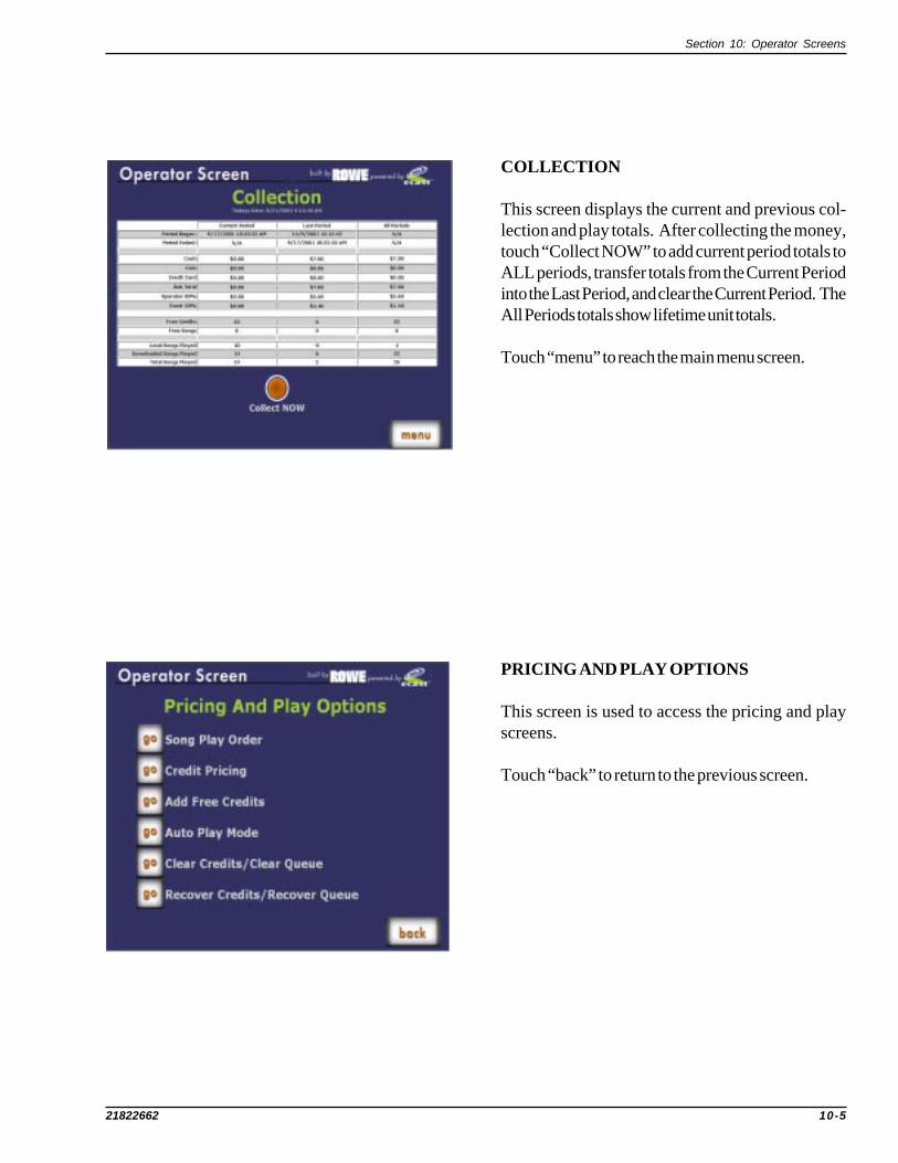
Section 10: Operator Screens
21822662 10-5
PRICING AND PLAY OPTIONS
This screen is used to access the pricing and playscreens.
Touch “back” to return to the previous screen.
COLLECTION
This screen displays the current and previous col-lection and play totals. After collecting the money,touch “Collect NOW” to add current period totals toALL periods, transfer totals from the Current Periodinto the Last Period, and clear the Current Period. TheAll Periods totals show lifetime unit totals.
Touch “menu” to reach the main menu screen.

DLW-1 Phonograph
10-6 21822662
SONG PLAY ORDER
Sets the music play for FIFO “First-in First-out” orRandom.
The button will turn orange when touched to indicatean active choice.
Touch "back" to return to the previous screen.
PRICING OPTIONS
Sets up pricing for selections.
The button will turn orange when touched to indicatean active choice.
Touch "back" to return to the previous screen.

Section 10: Operator Screens
21822662 10-7
AUTOPLAY MODE
Touch a button to set Autoplay OFF or ON. Thebutton will turn orange when touched to indicate anactive choice. If the phonograph is idle and Autoplayis ON, a random selection will play every 15, 20, or 30minutes. Touch the interval to select it.
Touch "back" to return to the previous screen.
ADD FREE CREDITS
Adds a credit each time “Add Credit” is touched.
Touch "back" to return to the previous screen.

DLW-1 Phonograph
10-8 21822662
CLEAR CREDITS/CLEAR QUEUE
Touch an orange button to clear all credits or the songqueue.
Touch "back" to return to the previous screen.
RECOVER CREDITS/RECOVER QUEUE
This screen is used to access the recover screens.
Touch "back" to return to the previous screen.

Section 10: Operator Screens
21822662 10-9
RECOVER QUEUE
Touch a button to select Queue Recovery OFF orON. The button will turn orange when touched toindicate an active choice.
To change the number of minutes, touch “ChangeInterval”. Use the keypad to enter the new value, thentouch CHANGE.
If you make a mistake touch CLEAR, re-enter thenew value, then touch CHANGE.
Touch "back" to return to the previous screen.
KEYPAD

DLW-1 Phonograph
10-10 21822662
RECOVER CREDITS
Touch a button to select Credit Recovery OFF orON. The button will turn orange when touched toindicate an active choice.
To change the number of minutes, touch “ChangeInterval”. Use the keypad to enter the new value, thentouch CHANGE.
If you make a mistake touch CLEAR, re-enter thenew value, then touch CHANGE.
Touch "back" to return to the previous screen.
KEYPAD

Section 10: Operator Screens
21822662 10-11
HARDWARE/DIAGNOSTICS
This screen is used to access the hardware anddiagnostic screens.
Touch "back" to return to the previous screen.
CALIBRATE TOUCHSCREEN
When this screen appears, close the phonographtop door and follow directions on the screen tocalibrate the touchscreen.
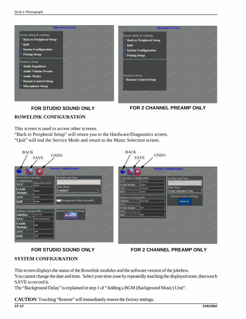
DLW-1 Phonograph
10-12 21822662
BACKSAVE UNDO
ROWELINK CONFIGURATION
This screen is used to access other screens.“Back to Peripheral Setup” will return you to the Hardware/Diagnostics screen.“Quit” will end the Service Mode and return to the Music Selection screen.
SYSTEM CONFIGURATION
This screen displays the status of the Rowelink modules and the software version of the jukebox.You cannot change the date and time. Select your time zone by repeatedly touching the displayed zone, then touchSAVE to record it.The “Background Delay” is explained in step 1 of “Adding a BGM (Background Music) Unit”.
CAUTION: Touching “Restore” will immediately restore the factory settings.
FOR STUDIO SOUND ONLY FOR 2 CHANNEL PREAMP ONLY
BACKSAVE UNDO
FOR STUDIO SOUND ONLY FOR 2 CHANNEL PREAMP ONLY

Section 10: Operator Screens
21822662 10-13
BACK SAVE UNDO
PRICING SETUP
Settings match the configuration of the electroniccoin mech and the Mars bill acceptor (25 = Quarter,100 = Dollar, etc.).
The settings are:Coin Bill1 = 0 1 = 1002 = 25 2 = 2003 = 100 3 = 5004 through 10 = 0 4 = 1000
5 = 20006 through 10 = 0
FOR STUDIO SOUND and 2 CHANNELPREAMP
BACK
AUDIO EQUALIZERS
Audio Equalizers have a default setting of +2.4 dbper frequency. Use the slider bar to change thesettings.
A room with carpet and drapery is a soft or highlyabsorbent location. A crowded room is also highlyabsorbent. These locations require greater empha-sis of high frequencies.
A room with paneled walls and a bare or tiled flooris a hard, nonabsorbent location, which requiresgreater low frequency emphasis.
Regardless of the room acoustics, the high and low frequency characteristics of your speakers can influencethe equalizer settings as much or more than the room acoustics.
FOR STUDIO SOUND ONLY

DLW-1 Phonograph
10-14 21822662
AUDIO VOLUME PRESETS
The Audio Volume Presets inputs are adjustable tomatch signal levels from the Core Computer soundcard and other sources to the front-end inputs andAVC circuitry of the Audio/Video Controller. Ifan input is set too low, the Audio/Video Controllermay not produce enough volume or its AVC cir-cuitry may not function properly. If set too high, theyellow clip indicator LED(s) on the 1000 wattamplifier will be off, but the sound will be distorted. Allinputs are factory set to 75%. The Sound Card inputshould be left at 75, but other inputs may need to beraised or lowered depending on the signal level ofsources connected to them.
The Audio Volume Presets outputs are adjustable to match the output level of the Audio/Video Controller to thespecified input level of different Power Amplifiers. The 60% factory setting is for the Rowe 1000 watt ExtremelyCool Audio Digital Power Amplifier. If it is set too high, the sound will be distorted at maximum volume or the musicmay disappear from one or both channels. If set too low, the power amplifier may not produce enough sound atmaximum volume. The Rowe power amplifier has yellow LED clip indicators that blink at maximum volume if thesetting is too high. Occasional blinking is normal, but frequent blinking means it is set too high and the audio willprobably sound too distorted, and the Power Amplifier may shut down.
To change a value touch it, and the Keypad window will appear on the screen. Follow directions on page 30 forusing the Keypad and saving the value(s) you enter.
BACK SAVEUNDO
FOR STUDIO SOUND ONLY
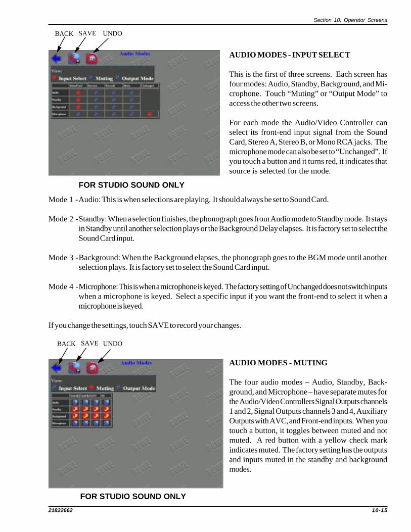
Section 10: Operator Screens
21822662 10-15
AUDIO MODES - INPUT SELECT
This is the first of three screens. Each screen hasfour modes: Audio, Standby, Background, and Mi-crophone. Touch “Muting” or “Output Mode” toaccess the other two screens.
For each mode the Audio/Video Controller canselect its front-end input signal from the SoundCard, Stereo A, Stereo B, or Mono RCA jacks. Themicrophone mode can also be set to “Unchanged”. Ifyou touch a button and it turns red, it indicates thatsource is selected for the mode.
AUDIO MODES - MUTING
The four audio modes – Audio, Standby, Back-ground, and Microphone – have separate mutes forthe Audio/Video Controllers Signal Outputs channels1 and 2, Signal Outputs channels 3 and 4, AuxiliaryOutputs with AVC, and Front-end inputs. When youtouch a button, it toggles between muted and notmuted. A red button with a yellow check markindicates muted. The factory setting has the outputsand inputs muted in the standby and backgroundmodes.
Mode 1 -Audio: This is when selections are playing. It should always be set to Sound Card.
Mode 2 -Standby: When a selection finishes, the phonograph goes from Audio mode to Standby mode. It staysin Standby until another selection plays or the Background Delay elapses. It is factory set to select theSound Card input.
Mode 3 -Background: When the Background elapses, the phonograph goes to the BGM mode until anotherselection plays. It is factory set to select the Sound Card input.
Mode 4 -Microphone: This is when a microphone is keyed. The factory setting of Unchanged does not switch inputswhen a microphone is keyed. Select a specific input if you want the front-end to select it when amicrophone is keyed.
If you change the settings, touch SAVE to record your changes.
UNDOBACK SAVE
UNDOBACK SAVE
FOR STUDIO SOUND ONLY
FOR STUDIO SOUND ONLY

DLW-1 Phonograph
10-16 21822662
AUDIO MODES - OUTPUT MODE
The Core Computer sound card outputs a stereosignal that connects to the STEREO MECHA-NISM INPUT RCA jacks on the Audio/VideoController. The Audio/Video Controller has cir-cuitry that combines the stereo signal to produce amono signal. It also has AUX RCA inputs for eachchannel. This screen lets you select what signal(stereo, mono, or AUX) shall be routed to the CH1,CH2, CH3, and CH4 SIGNAL OUTPUTS RCAjacks on the Audio/Video Controller for each ofthe four audio modes – Audio, Standby, Backgroundand Microphone.
When you touch a button, it toggles between red and blue. A red button indicates it is selected. The factory settingis stereo/stereo for all modes. If you select mono/mono for all modes, you can have separate volume control of eachchannel by selecting the corresponding channel linkage in the REMOTE CONTROL SETUP – PARAMETERSscreen (see Separate Volume Control of Speaker Zones).
If you change the settings, touch SAVE to record your changes.
BACK SAVE UNDO
FOR STUDIO SOUND ONLY

Section 10: Operator Screens
21822662 10-17
BACK SAVE UNDO
REMOTE CONTROL SETUP - PARAMETERS
This is the first of three screens. Touch “IR Settings” or “VCU Settings” to access those screens.
Remote Credit enables/disables credits being given by the IR remote and the VCU (volume control unit). ALWAYSenables remote credit but does not limit how many can be given. NEVER is the factory setting and disables them.CREDIT POOL limits the number of credits given each week to the value in Weekly Credit Pool. When you toucha button, it toggles between red and blue. A red button indicates it is selected.
Volume Control “Step Size” sets the amount of volume change each volume up/down key produces. Range is 1 to 5steps.
To change any value, touch it and the Keypad window will appear on the screen. Follow directions on page 9-30 forusing the Keypad and saving the value(s) you enter.
“Mode Linkage” is factory set to “Independent”, which means normal selections (paid or free), Background Music,and Autoplay selections have separate volumes and each type can only be adjusted when that type is playing. If youwant to lock Autoplays at a volume, then while an Autoplay is playing, adjust the volume then select “Locked Autoplay”.If you want Background Music and Autoplay volume to be equal, then select “Linked Background + Autoplay” (see“Adding a BGM Unit”).
“Channel Linkage” links the volume control of the channels together in the following combinations. Each time you toucha combination, the next choice will appear:
(Ch1, Ch2, Ch3, Ch4) channels 1, 2, 3, 4 linked (factory setting)(Ch1, Ch2); (Ch3, Ch4) channels 1, 2 linked - channels 3, 4 linked(Ch1, Ch2, Ch3); (Ch4) channels 1, 2, 3 linked - channel 4 separate(Ch1, Ch2, Ch4); (Ch3) channels 1, 2, 4 linked - channel 3 separate(Ch1, Ch3, Ch4); (Ch2) channels 1, 3, 4 linked - channel 2 separate(Ch2, Ch3, Ch4); (Ch1) channels 2, 3, 4 linked - channel 1 separate(Ch1, Ch2); (Ch3); (Ch4) channels 1, 2 linked - channels 3 and 4 separate(Ch1); (Ch2); (Ch3, Ch4) channels 1 and 2 separate - channels 3 and 4 linked(Ch1); (Ch2); (Ch3); (Ch4) all channels separate (four mono channels)(Ch1, Ch3); (Ch2, Ch4) channels 1, 3 linked - channels 2, 4 linked
If you change the settings, touch SAVE to record your changes.
BACK SAVE UNDO
FOR STUDIO SOUND ONLY FOR 2 CHANNEL PREAMP ONLY

DLW-1 Phonograph
10-18 21822662
REMOTE CONTROL SETUP - IR SETTINGS
IR SETTINGS:Enables or disables Autoplay Override, Pause, Reject, and Input Select on the IR. Factory settings disable all exceptReject. Touch on an item to change it. A red button with a yellow check mark indicates enabled.AUTOPLAY OVERRIDE:Allows remote to turn autoplay on or off.PAUSE:Pauses selection for a maximum of 10 minutes or until pause is pushed a second time – whichever comes first.REJECT:Allows IR remote to cancel selection playing.INPUT SELECT: Selects a different Front-end input each time input select is pushed. Do not enable this featureunless you require it.REJECT ALL: Cancel all selections in queue by holding IR reject button down for 4 seconds.
If you change the settings, touch SAVE to record your changes.
BACK SAVEUNDO BACK SAVE UNDO
FOR STUDIO SOUND ONLY FOR 2 CHANNEL PREAMP ONLY

Section 10: Operator Screens
21822662 10-19
REMOTE CONTROL SETUP - VCU SETTINGS
This screen enables and disables individual switcheson VCU’s (Volume Control Unit’s). Up to 4 VCU’scan be connected to the phonograph. This allowsdifferent rooms to have their own volume controlunit. To prevent a room from changing the volume,etc. of a different room, you can disable its switches asneeded.
When you touch a button, it toggles between enabledand disabled. A red button with a yellow checkmark indicates enabled. The factory setting enablesall switches except Credit on all 4 VCU’s.
If you change the settings, touch save to record your changes.
The phonograph comes with one VCU and its designated VCU1. If you add more VCU’s, you need to openthem and set the two position dip switch as follows:
VCU1 position 1 OFF position 2 OFFVCU2 position 1 OFF position 2 ONVCU3 position 1 ON position 2 OFFVCU4 position 1 ON position 2 ON
BACK SAVEUNDO
FOR STUDIO SOUND ONLY

DLW-1 Phonograph
10-20 21822662
MICROPHONE SETUP - SETUP
This is the first of two microphone screens. Touch“Routing” to access the other screen.
The microphones TYPE are factory set to “Paging”indicated by the red buttons and should not bechanged to NA. If a paging button is blue, touch itto make it red.
The “Volume (dB)” displays the volume settings forthe microphones.
The “Override (dB)” sets how low the music volumedrops when a microphone is keyed. The factorysettings are 33. The lower the value, the more it drops.To change a value, touch it and the Keypad windowwill appear on the screen. Follow directions on page9-12 for using the Keypad and saving the value(s) youenter.
BACK SAVEUNDO
BACK SAVEUNDO
MICROPHONE SETUP - ROUTING
Each microphone can be routed to any of the sixoutputs (four channels and two aux).
When you touch a button, it toggles between routedand not routed. A red button with a yellow checkmark indicates routed. The factory setting routesall microphones to all six outputs.
If you change the settings, touch SAVE to record yourchanges.
FOR STUDIO SOUND ONLY
FOR STUDIO SOUND ONLY

Section 10: Operator Screens
21822662 10-21
SYSTEM SETTINGS
A read-only screen showing the system settings andstatus.
NETWORK SETTINGS
A read-only screen the showing network settings andstatus.
SYSTEM DIAGNOSTICS
This screen is used to access the diagnostic screens.
Touch "back" to return to the previous screen.

DLW-1 Phonograph
10-22 21822662
QUICK DIAGNOSTICS
A read-only screen used for diagnostics.
NETWORK DIAGNOSTICS
A read-only screen used for diagnostics.
APPLICATION LOGS
A read-only screen used for diagnostics.
Touch "back" to return to the previous screen.

Section 10: Operator Screens
21822662 10-23
UPDATE CONTROLLER
CAUTION: Do not use the “Force Update” featurewithout prior approval from Customer Service.
CONFIGURATION SUMMARY
A read-only screen.
MUSIC FILTER
Categories with a check mark will not be played onthis machine. Place or remove a check mark bytouching the white box.
Touch "back" to return to the previous screen.

DLW-1 Phonograph
10-24 21822662
SPANISH USER INTERFACE

Section 10: Operator Screens
21822662 10-25
ADDING A BGM (BACKGROUND MUSIC) UNIT STUDIO SOUND ONLY
Do not skip steps. All steps must be done to navigate properly through the menus. If you get lost, back through the menus bytouching: back, the back arrow, or Back to Peripheral Setup.
Step 1. Set the Background Music Delay. The delay is the number of seconds that elapse before Background Musicplays. Time starts elapsing when the DLW-1 is at standby. To prevent background music between songs, set thedelay to 10 or more seconds.
• Push SERVICE SWITCH to enter Main Menu.• Touch Hardware/Diagnostics.• Touch Configure Hardware.• Touch System Configuration.
• Touch box showing seconds of Background Delay.• Touch C to clear the present value, enter the seconds of delay you desire, and touch OK.• Touch SAVE arrow to record your changes• Touch BACK arrow to return to System Admin & Auditing.
Step 2. Plug a stereo BGM unit into the left and right Stereo A (BGM) Input, or Plug a mono BGM unit into theMono C (BGM) Input.
• Touch Audio Modes to view Audio Modes, Input Select screen.• In the Background row, Touch the input you plugged the BGM unit into.• Touch Muting to view Audio Modes, Muting screen.• In the Background row, remove all check marks by touching them.• Touch SAVE arrow to record your changes• Touch BACK arrow to return to Hardware Setup.
Step 3. If the BGM unit has tone controls, set them for a flat response. Adjust the phonograph to a comfortablevolume and listen to the Background Music. If the BGM unit has a volume control, increase it until the music startsto distort, then reduce it a little ways past where it no longer distorts. If the BGM unit does not have a volume control,and the BGM music sounds good (i.e. it’s stable and not distorted), then skip to step 4.
When the Audio/Video Controller, Preset Input is at factory setting, a BGM signal greater than 1.0 volt is too highand may cause distortion. A signal less than 0.4 volt is too low and may cause unstable sound. If the BGM musicis distorted or if the music is not stable, adjust the input of the Audio/Video Controller as follows:
• Touch Audio Volume Presets.• Touch the box (Stereo A, or Mono) you plugged the BGM unit into.• Touch C to clear the present value. Enter a lower value if music is distorted. Enter a higher value if music
is not stable. Touch OK, then Touch SAVE arrow. If still distorted or not stable keep repeating “Touch C ,enter new value, Touch OK, and Touch SAVE arrow” until its stable and not distorted.
• Touch BACK arrow to return to Hardware Setup.
Step 4. The factory settings configure the phonograph for independent volume adjustment of music played by:customers, autoplay, and Background Music. You are adjusting the volume of: customer music when customermusic is playing, autoplay when autoplay music is playing, and Background Music when Background Music isplaying. If you want Background Music and autoplay music to have the same volume, then link them by doing thefollowing. Otherwise touch Quit.
• Touch Remote Control Setup to view Remote Control Setup, Parameters screen.• Touch Linked Background + Autoplay• Touch SAVE arrow to record your changes• Touch BACK arrow to return to Hardware Setup.• Touch Quit.

DLW-1 Phonograph
10-26 21822662
ADDING MICROPHONES STUDIO SOUND ONLY
Do not skip steps. All steps must be done to navigate properly through the menus. If you get lost, back through the menus bytouching: BACK, the BACK arrow, or Back to Peripheral Setup.
Up to three microphones can be plugged into the Audio/Video Controller and used for paging. Microphones can be Rowe, low-level balanced, or low-level unbalanced. All microphones must have a momentary PUSH to TALK switch (see Figure xxx).
Step 1. Check microphone muting, Mic type, and VCU settings:• Push SERVICE SWITCH to enter Main Menu.• Touch Hardware/Diagnostics.• Touch Configure Hardware.• Touch Audio Modes to view Audio Modes, Input Select screen.• Touch Muting to view Audio Modes, Muting screen.
• In the Microphone row, remove any check marks by touching them.• Touch BACK arrow to return to Hardware Setup.• Touch Microphone Setup to view Microphone Setup, Setup screen.
• The paging column should have all red dots. Touch any blue to make it red.• Touch BACK arrow to return to Hardware Setup.• Touch Remote Control Setup to view Remote Control, Parameters screen.• Touch VCU Settings to view Remote Control, VCU Settings screen.
• In the VCU1 row, touch the microphones you are adding, that do not have a check mark.• Touch SAVE arrow to record your changes
Step 2. Plug in the microphone(s). If you are adding only low-level microphones, go to Step 3. Rowe microphoneshave a built-in volume control, but are also affected by the microphone volume settings of the phonograph VolumeControl Unit. Set the volume control on each Rowe microphone you are adding to maximum, and do a test pagewith them. Remove any distortion by lowering the corresponding microphone volume on the phonograph VolumeControl Unit. Then do the following to disable those microphone keys on the VCU.
• Touch Parameters to view Remote Control, Parameters screen.• Touch VCU Settings to view Remote Control, VCU Settings screen.
• In the VCU1 row, remove check marks corresponding to Rowe microphones by touching them.• Touch SAVE arrow to record your changes
Step 3. Use the phonographs’ Volume Control Unit to control the volume of the low-level microphones. Do a testpage with each low-level microphone.
Step 4. During paging, the music level drops to whichever is greater: 6 db or the override settings. Each channelhas its own override setting in the range of 0 to 63, and channels 1, 2, 3, and 4 are factory set to 33. Set to 63 ifyou want minimum reduction of the music. To change the override settings:
• Touch BACK arrow to return to Hardware Setup.• Touch Microphone Setup to show Microphone Setup, Setup screen.• For each override setting.
• Touch box showing override value.• Touch C to clear the present value, enter the new value, and touch OK.
• Touch SAVE arrow to record your changes
Step 5. Each microphone can be routed to any combination of the six output channels: 1, 2, 3, 4, AuxL, and AuxR.The factory setting route all 3 microphones to all six output channels. To change the routing:
• Touch Routing to show Microphone Setup, Routing screen.• Set the routing for each microphone. When you touch a button, it toggles between routed and not routed. A red
button with a yellow check mark indicates routed.• Touch SAVE arrow to record your changes.• Touch BACK arrow to return to Hardware Setup.

Section 10: Operator Screens
21822662 10-27
Step 6. When a microphone is keyed, the Audio/Video Controller can select its front-end input signal from theSound Card, Stereo A, Stereo B, Mono, or Unchanged. The factory setting of Unchanged does not switch front-end inputs when a microphone is keyed. Do the following if you want a specific front-end input, else Touch Quit.
• Touch Audio Modes to view Audio Modes, Input Select screen.• In the Microphone row, touch the front-end input you want.• Touch SAVE arrow to record your changes.
• Touch BACK arrow to return to Hardware Setup.• Touch Quit.

DLW-1 Phonograph
10-28 21822662
TIP
SLEEVE
RIN
G
MIC
ROPHONE
�CASE
MIC
ROPHONE
�CASE
TIP
SLEEVE
RIN
G
MIC
ROPHONE
�CASE
MIC
ROPHONE
�CASE
MONO
�1/
4�IN
CH
�MALE
�PLUG
MONO
�1/
4�IN
CH
�MALE
�PLUG
STEREO
�1/
4�IN
CH
�MALE
�PLUG
STEREO
�1/
4�IN
CH
�MALE
�PLUG
TIP
RIN
G SLEEVE
TWIS
TED
�PAIR
TWIS
TED
�PAIR
OUTSID
E�SHEIL
DOUTSID
E�SHEIL
D
CASE
�GROUND
CASE
�GROUND
SIG
NAL
�IN
SIG
NAL
�IN
GROUND
+15
�VOLTS
+15
�VOLTS
MIC
�SW.
MIC
�SW.
MIC
AMP
ROWE
�MIC
ROPHONE
ROWE
�MIC
ROPHONE
STAND/HANDHELD
BALANCE
�MIC
ROPHONE
BALANCE
�MIC
ROPHONE
UNBALANCE
�MIC
ROPHONE
UNBALANCE
�MIC
ROPHONE
MIC
LEVEL
ADJUST
PUSH
�TO
PUSH
�TO
TALK
SWIT
CH
PUSH
�TO
PUSH
�TO
TALK
SWIT
CH
PUSH
�TO
PUSH
�TO
TALK
SWIT
CH
MOMENTARY
INTERNAL
�SHORTIN
GIN
TERNAL
�SHORTIN
G
SWIT
CH
�OPENS
�FOR
SWIT
CH
�OPENS
�FOR
PAGE.�CLOSES
�TO
�MUTE
PAGE.�CLOSES
�TO
�MUTE
AUDIO
/VID
EO
�CONTROLLER
AUDIO
/VID
EO
�CONTROLLER
MIC
ROPHONE
�IN
PUT
MIC
ROPHONE
�IN
PUT
JACKS/CONNECTORS
1 2 3 4 5
1 2 3 4 5
J30,
�J35
�&
�J45
J30,
�J35
�&
�J45
UNBALANCED
�MIC
.�IN
PUTS
UNBALANCED
�MIC
.�IN
PUTS
TIP
SLEEVE
J30,
�J35
�&
�J45
J30,
�J35
�&
�J45
BALANCED
�MIC
.�IN
PUTS
BALANCED
�MIC
.�IN
PUTS
P2,P
5,&
P6
10K
55
44
33
22
11
DD
CC
BB
AA
STUDIO SOUND ONLY

Section 10: Operator Screens
21822662 10-29
SEPARATE VOLUME CONTROL of SPEAKER ZONES STUDIO SOUND ONLY
Do not skip steps. All steps must be done to navigate properly through the menus. If you get lost, back through themenus by touching: back, the back arrow, or Back to Peripheral Setup.
TWO MONO ZONES or FOUR MONO ZONES
The Main/Phono Amplifier gets its input from Audio/Video Controller outputs Ch1 and Ch2 and supplies two mono zones. Asecond amplifier, with its inputs connected to Audio/Video Controller outputs Ch3 and Ch4, would supply two additionalmono zones.
Step 1. Set the output mode of Audio/Video Controller to mono/mono.• Push SERVICE SWITCH to enter Main Menu.• Touch Hardware/Diagnostics.• Touch Configure Hardware.• Touch Audio Modes to view Audio Modes, Input Select screen.
• Touch Output Mode to view Audio Modes, Output Mode screen.• The mono/mono column needs to have all red dots. Touch blue to make it red.• Touch BACK arrow to return to Hardware Setup.
Step 2. Set the Channel linkage for separate volume control.• Touch Remote Control Setup to view Remote Control, Parameters screen.• Repeatedly Touch the Channel Linkage choices until it shows (Ch1); (Ch2); (Ch3); (Ch4)• Touch SAVE arrow to record your changes.• Touch BACK arrow to return to Hardware Setup.• Touch Quit.
TWO MONO ZONES and ONE STEREO ZONE
This requires a second amplifier. The Main/Phono Amplifier gets its input from Audio/Video Controller outputs Ch1and Ch2 and supplies two mono zones. The second amplifier gets its input from Audio/Video Controller outputs Ch3 andCh4 and supplies a stereo zone.
Step 1. Set the output mode of Audio/Video Controller Ch1&Ch2 to mono/mono, and Ch3&Ch4 to stereo/stereo.• Push SERVICE SWITCH to enter Main Menu.• Touch Hardware/Diagnostics.• Touch Configure Hardware.• Touch Audio Modes to view Audio Modes, Input Select screen.
• Touch Output Mode to view Audio Modes, Output Mode screen.• The mono/mono column needs to have red dots for all Ch1&Ch2. Touch blue to make it red.• The stereo/stereo column needs to have red dots for all Ch3&Ch4. Touch blue to make it red.• Touch BACK arrow to return to Hardware Setup.
Step 2. Set the Channel linkage for separate volume control of Ch1&Ch2, and linked control of Ch3&Ch4.• Touch Remote Control Setup to view Remote Control, Parameters screen.• Repeatedly Touch the Channel Linkage choices until it shows (Ch1); (Ch2); (Ch3, Ch4)• Touch SAVE arrow to record your changes.• Touch BACK arrow to return to Hardware Setup.• Touch Quit.

DLW-1 Phonograph
10-30 21822662
ONE STEREO ZONE and TWO MONO ZONES
This requires a second amplifier. The Main/Phono Amplifier gets its input from Audio/Video Controller outputs Ch1and Ch2 and supplies a stereo zone. The second amplifier gets its input from Audio/Video Controller outputs Ch3 and Ch4and supplies two mono zones.
Step 1. Set the output mode of Audio/Video Controller Ch1&Ch2 to stereo/stereo, and Ch3&Ch4 to mono/mono.• Push SERVICE SWITCH to enter Main Menu.• Touch Hardware/Diagnostics.• Touch Configure Hardware.• Touch Audio Modes to view Audio Modes, Input Select screen.
• Touch Output Mode to view Audio Modes, Output Mode screen.• The stereo/stereo column needs to have red dots for all Ch1&Ch2. Touch blue to make it red.• The mono/mono column needs to have red dots for all Ch3&Ch4. Touch blue to make it red.• Touch BACK arrow to return to Hardware Setup.
Step 2. Set the Channel linkage for linked control of Ch1&Ch2, and of separate volume control Ch3&Ch4.• Touch Remote Control Setup to view Remote Control, Parameters screen.• Repeatedly Touch the Channel Linkage choices until it shows (Ch1, Ch2); (Ch3); (Ch4)• Touch SAVE arrow to record your changes.• Touch BACK arrow to return to Hardware Setup.• Touch Quit.
TWO STEREO ZONES
This requires a second amplifier. The Main/Phono Amplifier gets its input from Audio/Video Controller outputs Ch1 andCh2 and supplies one stereo zone. The second amplifier gets its input from Audio/Video Controller outputs Ch3 and Ch4and supplies another stereo zone.
Step 1. Set the output mode of Audio/Video Controller to mono/mono.• Push SERVICE SWITCH to enter Main Menu.• Touch Hardware/Diagnostics.• Touch Configure Hardware.• Touch Audio Modes to view Audio Modes, Input Select screen.
• Touch Output Mode to view Audio Modes, Output Mode screen.• The stereo/stereo column needs to have all red dots. Touch blue to make it red.• Touch BACK arrow to return to Hardware Setup.
Step 2. Set the Channel linkage for linked volume control of Ch1&Ch2, and linked volume control of Ch3&Ch4• Touch Remote Control Setup to view Remote Control, Parameters screen.• Repeatedly Touch the Channel Linkage choices until it shows (Ch1, Ch2); (Ch3, Ch4)• Touch SAVE arrow to record your changes.• Touch BACK arrow to return to Hardware Setup.• Touch Quit.

Section 10: Operator Screens
21822662 10-31
KEYPAD
Operator Screen Programming may require numbers to be input on the various screens. When this is the case,a pop-up keypad will appear on the screen with a value in it from the space you touched. Touch C to clearthe value, enter the value desired, and press OK. The D key deletes the last digit entered.
After entering all your values, touch the SAVE button on the operator screen to have the new value(s) take effect.

DLW-1 Phonograph
10-32 21822662
This page left intentionally blank

INTRODUCTION ....................................................................................................................................... 11-3
Catalog Description ......................................................................................................................... 11-3
Parts List Description ...................................................................................................................... 11-3
Ordering Replacement Parts ........................................................................................................... 11-3
MAIN DOOR ASSEMBLY (EXTERNAL VIEW) 17" FLAT SCREEN ...................................................... 11-4
MAIN DOOR ASSEMBLY (EXTERNAL VIEW) 15" FLAT SCREEN ...................................................... 11-6
MAIN DOOR ASSEMBLY (INTERNAL VIEW) 15" and 17" FLAT SCREEN ......................................... 11-8
SHELL ASSEMBLY (INTERNAL VIEW) 1000 WATT STUDIO SOUND .............................................. 11-12
SHELL ASSEMBLY (INTERNAL VIEW) 1000 WATT 2 CHANNEL PREAMP ..................................... 11-13
CORE COMPUTER ASSEMBLY ........................................................................................................... 11-18
I/O SUBASSEMBLY - LEFT .................................................................................................................. 11-20
I/O SUBASSEMBLY - RIGHT ................................................................................................................ 11-21
INTERMEDIATE BOARD SUB-ASSEMBLY ......................................................................................... 11-22
COMPUTER DRIVE DOOR ASSEMBLY............................................................................................... 11-23
POWER SUPPLY ASSEMBLY .............................................................................................................. 11-24
A/V CONTROLLER - 4 CHANNEL ........................................................................................................ 11-25
2 CHANNEL PREAMP ........................................................................................................................... 11-26
OUTPUT TRANSFORMER ASSEMBLY ............................................................................................... 11-27
ROWELINK CONTROLLER ASSEMBLY ............................................................................................. 11-28
HANGER BRACKET ASSEMBLY ......................................................................................................... 11-29
ACCESSORY EQUIPMENT ................................................................................................................... 11-30
Section 11: Parts Catalog
11-1

11-2 21822662
This page intentionally left blank.

11-321822662
INTRODUCTIONThis parts catalog lists replacement parts for the phonograph. The purpose of this parts catalog is to
locate and identify replaceable components and supply information on how to order them.
Catalog DescriptionThis catalog is divided into major sections labeled with figure numbers, which correspond to the
illustrations used. Some assemblies require more than one illustration to identify the parts. Each
page has a sheet number to identify the sheet as part of that assembly's parts list.
Replacing parts that are welded or riveted onto an assembly is normally impractical. Therefore,
replacement parts are not listed for these items. The assembly containing the welded or riveted part
should be replaced.
Parts List DescriptionThe parts list contains four columns:
· Figure, Sheet, and Index Number — The first entry in this column is the figure number of the
corresponding illustration. An index number, when listed, corresponds to the index number
appearing on the illustration. Index numbers are not used when items are listed for reference
purposes only or when the item listed is an alternate part.
· Rowe Part Number — This column lists the part number to use when ordering replacement
parts or making inquiries.
· Description — This column gives a word description of each part or assembly. Each item is
indented to show its relationship to the next higher assembly.
· Qty — This column contains the part quantity used in the assembly. When a figure describes
more than one model of an assembly, the “Qty” column is divided to show each model.
Ordering Replacement PartsAll replacement parts must be ordered directly from an Authorized Rowe® Distributor.
Once the replacement item has been determined, complete a Standard Parts Order Form (availablefrom your Rowe® Distributor at no charge). Very often, parts orders are delayed because ofinadequate or incomplete parts order forms. To enable prompt delivery, always specify the followinginformation:
· Part Number and Description (indicate color, if applicable)
· Quantity Required
· Machine Model and Serial Number
· Complete Shipping Address, including the ZIP code
· Shipping Instructions must be supplied. If the shipping method is Parcel Post, Air Parcel Post,United Parcel Service, or Air UPS, and the packages may exceed the size and weight limitsof these services, indicate an alternate shipping method.
If the shipment must be delivered as fast as possible, specify “Fastest Way”. Rowe® will select the
carrier for orders that justify shipment by truck.

11-4 21822662
Figure 11-1. Main Door Assembly (External View)7" FLAT SCREEN
Internet Jukebox
1
2
3
4
5
StarlinkStarlink
6

11-521822662
Figure 11-1. Main Door Assembly (External View) 17" FLAT SCREEN
Ref. Part No. Description Qty
22152001 Main Door Assembly (Silver) ............................................................................Ref.
22152002 Main Door Assembly (Black) ............................................................................Ref.
1 22148001 Center Door Panel (Silver/Grey) .......................................................................... 1
22148002 Center Door Panel (Black/Grey) .......................................................................... 1
2 22149202/03 Lower Logo Glass (02 Lavender background, 03 Red/Orange background) ... 1
3 22148102/01 Lens - Wing (Left) (01 Translucent White, 02 Translucent) ................................. 1
4 22148202/01 Lens - Wing (Right) (01 Translucent White, 02 Translucent) ............................... 1
5 22149302 Upper Logo Glass ................................................................................................. 1
6 22152701 Neon Assembly - Straight (for 22152001 Main Door - Silver) ............................. 1
22152801 Neon Assembly - Curved (for 22152002 Main Door - Black) .............................. 1

11-6 21822662
Internet Jukebox
1
2
3
4
5
StarlinkStarlink
6
7
Figure 11-1A. Main Door Assembly (External View) 15" FLAT SCREEN

11-721822662
Figure 11-1A. Main Door Assembly (External View) 15" FLAT SCREEN
Ref. Part No. Description Qty
22152003 Main Door Assembly (Silver) ............................................................................Ref.
22152004 Main Door Assembly (Black) ............................................................................Ref.
1 22148001 Center Door Panel (Silver/Grey) .......................................................................... 1
22148002 Center Door Panel (Black/Grey) .......................................................................... 1
2 22149202/03 Lower Logo Glass (02 Lavender background, 03 Red/Orange background) ... 1
3 22148102/01 Lens - Wing (Left) (01 Translucent White, 02 Translucent) ................................. 1
4 22148202/01 Lens - Wing (Right) (01 Translucent White, 02 Translucent) ............................... 1
5 22149302 Upper Logo Glass ................................................................................................. 1
6 22152701 Neon Assembly - Straight (for 22152003 Main Door - Silver) ............................. 1
22152801 Neon Assembly - Curved (for 22152004 Main Door - Black) .............................. 1
7 61139301 Bezel - Adaptor 15" Flatscreen ............................................................................ 1

11-8 21822662
Figure 11-2. Main Door Assembly (Internal View)
4��
5**
23
24
7
6
8 9 10 21 12 13**
22
11
20
15, 16
14
3 2 1
17, 18, 19
17" Flat Screen
25
15" Flat Screen

11-921822662
Figure 11-2. Main Door Assembly (Internal View)
Ref. Part No. Description Qty
22152001 Main Door Assembly (Silver/Grey) ..................................................................Ref.
22152002 Main Door Assembly (Black/Grey) ..................................................................Ref.
1 22149701 Security Bracket - Top .......................................................................................... 1
80443004 #8-32 x 1/4 Hex WRHMS ....................................................................................... 4
2 22151901 17" Flat Screen w/Mount ........................................................................................ 1
89293608 #8 x 1/2 Hex WRHS Hi-Lo ..................................................................................... 9
3 22148501 Bracket - Top ......................................................................................................... 1
89293008 #8 x 1/2 Hex WRHS Hi-Lo ..................................................................................... 2
22151601 Top Bracket and Light Assembly ......................................................................... 1
70060103 Lamp - Fluorescent ............................................................................................... 1
89293605 #8 x 5/16 Hex WRHS Hi-Lo ................................................................................... 2
4 22148301 Extrusion - Door Side ............................................................................................ 2
89293008 #8 x 1/2 Hex WRHS Hi-Lo ..................................................................................... 2
61137701 C Channel (LH) ...................................................................................................... 1
61137801 C Channel (RH) ..................................................................................................... 1
89293605 #8 x 5/16 Hex WRHS Hi-Lo ................................................................................. 12
5** 22135602 Bill Acceptor ........................................................................................................... 1
6 22149901 Bracket - Security (Side) ....................................................................................... 1
80443006 #8-32 x 3/8 Hex WRHMS (SF) ............................................................................... 8
7 22149501 Strike - Door ........................................................................................................... 2
80443006 #8-32 x 3/8 Hex WRHMS ....................................................................................... 6
8 22117201 Clip - Neon Bulb (for Black Phonographs) ........................................................... 6
22117201 Clip - Neon Bulb (for Silver Phonographs) ........................................................... 4
9 22149801 Bracket - Security Bottom ..................................................................................... 1
80443004 #8-32 x 1/4 Hex WRHMS ....................................................................................... 3
10 22148601 Bracket - Bottom .................................................................................................... 1
89293608 #8 x 1/2 Hex WRHS Hi-Lo ..................................................................................... 3
11 34041801 Bracket - Glass Retainer (Bottom) ....................................................................... 1
89293605 #8 x 5/16 Hex WRHS Hi-Lo ................................................................................... 2
12 22153802 Flat Screen Power Supply .................................................................................... 1
13** 22152501 Card Reader Assembly ....................................................................................... 1
14 22148701 Clamp - Wing ........................................................................................................ 6
80443006 #8-32 x 3/8 Hex WRHMS (SF) ............................................................................. 12
15 34041601 Ballast - Two Lamp 50/60 Hz ................................................................................ 1
16 34043301 Ballast Mounting Bracket ....................................................................................... 1
17 34043201 Neon Transformer Mounting Bracket .................................................................... 1
18 34043101 Neon Power Supply Shield ................................................................................... 1
19 34015304 Power Supply Transformer .................................................................................. 1
20 22151701 Light Assembly - Logo (Lower) ............................................................................ 1
89293605 #8 x 5/16 Hex WRHS Hi-Lo ................................................................................... 2
70060103 Lamp - Fluorescent ............................................................................................... 1
Continued on Page 11-10

11-10 21822662
Figure 11-2. Main Door Assembly (Internal View)
Continued from Page 10-9
Ref. Part No. Description Qty
21 22153901 Bracket Assembly - Flatscreen Transformer ...................................................... 1
80443006 #8-32 x 3/8 Hex WRHMS (SF) ............................................................................... 1
22 22148901 Hinge - Door ........................................................................................................... 1
80443006 #8-32 x 3/8 Hex WRHMS ....................................................................................... 9
23 34041501 Bracket - Chute Mounting (Door) .......................................................................... 1
89293006 #8 x 3/8 Hex WRHS (Hi-Lo) ................................................................................... 3
24 40927601 Chute - Coin Door ................................................................................................. 1
80443006 #8-32 x 3/8 Hex WRHMS ....................................................................................... 4
25 22160801 15" Flat Screen w/Mount ........................................................................................ 1
NOT SHOWN:34039910 Harness - Neon Interconnect ................................................................................ 1
34038902 Harness - Mod Card Reader ................................................................................ 1
40898710 Harness - Door (120 V) ......................................................................................... 1
(**) NOT INCLUDED AS PART OF DOOR ASSEMBLY

11-1121822662
This page intentionally left blank

11-12 21822662
Figure 11-3. Shell Assembly (Internal View) 1000 Watt Studio Sound
1
2
3
5
6
7
8
9
10
11
12
13
14
15
16
17
18
19
20
21
2223
4

11-1321822662
7
8
Figure 11-3A. Shell Assembly (Internal View) 1000 Watt 2 ChannelPreamp

11-14 21822662
Figure 11-3B. Shell Assembly (Internal View)
1000 Watt Studio Sound and 1000 Watt 2 Channel Preamp
24
25 26
27
28
29
30
Components in this view are common to theStudio Sound and 2 Channel Preamp

11-1521822662
Figure 11-3, 11-3A, and 11-3B. Shell Assembly (Internal View)
1000 Watt Studio Sound and 1000 Watt 2 Channel Preamp
Ref. Part No. Description Qty
Shell Assembly Internal View............................................................................................ Ref.
1 22147401 Shell Assembly .................................................................................................................... 1
2 22143802 Core Computer Assembly (See Figure 11-4) ......................................................................... 1
22146601 Computer Mounting Bracket (Left) ......................................................................................... 1
22146701 Computer Mounting Bracket (Rear) ....................................................................................... 1
80443006 #8-32 x 3/8 Hex WRHMS (Thread Forming) .......................................................................... 4
3 22150201 UPS Support (Right) ............................................................................................................ 1
80443006 #8-32 x 3/8 Hex WRHMS (Thread Forming) .......................................................................... 2
4 22150101 UPS Support (Left) ............................................................................................................... 1
80443006 #8-32 x 3/8 Hex WRHMS (Thread Forming) .......................................................................... 2
5 40927401 UPS - 320SL ....................................................................................................................... 1
34040901 CBA - UPS Interface ............................................................................................................ 1
6 61132003 Amplifier - Extra Cool Audio (1000 Watt) ............................................................................... 1
80443006 #8-32 x 3/8 Hex WRHMS (Thread Forming) .......................................................................... 4
7 40917401 A/V Controller - 4 Channel (see Figure 11-10) for 1000 Watt Studio Sound ............................ 1
61138701 Preamp Assembly - 2 Channel ............................................................................................ 1
8 34032903 Volume Control Unit for 1000 Watt Studio Sound ................................................................... 1
22145604 Switch and Volume Control Assembly for 1000 Watt 2 Channel Preamp ............................... 1
86663610 #8 x 5/8 Hex WRHS Type 17 .............................................................................................. 4
9 22146901 Retainer- Coin Container ...................................................................................................... 1
20922502 Spacer ................................................................................................................................. 1
86663610 #8 x 5/8 Hex WRHS Type 17 .............................................................................................. 1
21256201 Tension Spring ..................................................................................................................... 1
70091702 Lug - Solder ......................................................................................................................... 1
10 22146801 Container - Coins ................................................................................................................. 1
11 34008301 Chute - Slug ......................................................................................................................... 1
80662308 #6-32 x 1/2 Hex WRHMS .................................................................................................... 1
21357802 #6-32 Elastic Stop Nut .......................................................................................................... 1
12 70091702 Lug - Solder ......................................................................................................................... 1
13 21256201 Spring - Tension ................................................................................................................... 1
14 30984404 Holder Assembly - Coin Mech .............................................................................................. 1
86663610 #8 x 5/8 Hex WRHS Type 17 .............................................................................................. 2
15 21865308 Link ...................................................................................................................................... 1
16 40927701 Chute - Coin (Cabinet) ......................................................................................................... 1
80443006 #8-32 x 3/8 Hex WRHMS .................................................................................................... 6
17 40927801 Coin Chute Mounting Bracket (Cabinet) ................................................................................ 1
86663610 #8 x 5/8 Hex WRHS Type 17 .............................................................................................. 3
18 21998204 Coupler - Latch .................................................................................................................... 1
19 22120301 Bracket - Lock Guide ............................................................................................................ 1
86663610 #8 x 5/8 Hex WRHS Type 17 .............................................................................................. 3
20 21947403 Lockbar Assembly ............................................................................................................... 2
20922502 Spacer ................................................................................................................................. 4
86663610 #8 x 5/8 Hex WRHS Type 17 .............................................................................................. 4
Continued on Page 11-16

11-16 21822662
Figure 11-3, 11-3A and 11-3B. Shell Assembly (Internal View)
1000 Watt Studio Sound and 1000 Watt 2 Channel Preamp
Continued from Page 11-15
Ref. Part No. Description Qty
21 21946301 Plate - Lockbar ...................................................................................................... 1
22 22145801 Power Supply Assembly (See Figure 11-9) ........................................................ 1
23 40737803 Power Transformer ............................................................................................... 1
24 40832108 Audio Output Transformer (See Figure 11-11) .................................................... 1
22146501 Bracket - Audio Output Transformer .................................................................... 1
22121701 Carriage Bolt ......................................................................................................... 4
87844400 #10-32 Keps Nut .................................................................................................... 4
25 40926001 Rowelink Controller Assembly (See Figure 11-12) ............................................. 1
86663610 #8 x 5/8 Hex WRHS Type 17 ................................................................................ 4
26 30781702 Cup - Slug (Black) ................................................................................................. 1
21792901 Door - Slug Cup ..................................................................................................... 1
21793001 Bracket - Slug Cup ................................................................................................ 1
70120010 Washer .................................................................................................................. 1
86663610 #8 x 5/8 Hex WRHS Type 17 ................................................................................ 2
27 34007701 Bezel - Reject Button............................................................................................. 1
34007601 Button - Reject ....................................................................................................... 1
28 70163215 Cylinder Lock ......................................................................................................... 1
21947501 Washer - Indexing ................................................................................................. 1
21425601 Lockbolt .................................................................................................................. 1
29 40702817 Skid Rail ................................................................................................................. 2
30 34040901 CBA - UPS Interface.............................................................................................. 1

11-1721822662
This page intentionally left blank

11-18 21822662
Figure 11-4. Core Computer Assembly
12
34
56
7
89
1011
12
13
1415
1617
1819
2021
2223
24
25
26
27

11-1921822662
Figure 11-4. Core Computer Assembly
Ref. Part No. Description Qty
22143802 Core Computer Assembly ...............................................................................Ref.
1 22143901 Chassis - Core Computer .................................................................................... 1
2 80443006 #8-32 x 3/8 Hex Wrhs (SF) ................................................................................. 28
3 80351608 #4-40 x 1/2 Rdhms ................................................................................................ 7
4 22144301 Bracket - Computer Card Mounting ..................................................................... 1
5 22142202 Label - Wiring (RES/ATX PWR/USB) .................................................................. 1
6 22144001 Panel - Left (Computer) ........................................................................................ 1
7 22144401 Cover - Computer Card ....................................................................................... 1
8 22140402 Cable - Ethernet .................................................................................................... 1
9 22144601 Panel - Front (Computer) ...................................................................................... 1
10 22145401 I/O Sub-assembly - Right (Computer) (See Figure 11-6) ................................... 1
11 70122009 Washer - #8 Internal Lock ..................................................................................... 4
12 22145301 I/O Sub-assembly - Left (Computer) (See Figure 11-5) ...................................... 1
13 22144101 Door Assembly - Drive (Computer) (See Figure 11-8) ...................................... 1
14 22132214 Cable Assembly - Dr-Rib CC Hard Dr ................................................................ 1
15 34037802 Cable - PCM-6890 HD ........................................................................................... 1
16 22150601 Intermediate Board Sub-assembly (See Figure 11-7) ........................................ 1
17 40924203 Single Board Computer W/CPU, RAM ................................................................ 1
18 87843000 #8-32 Keps Hex Nut ............................................................................................... 4
19 22150701 Fan - Computer ..................................................................................................... 1
20 22145201 Bracket - Cable Retainer ...................................................................................... 2
21 87831600 #4-40 Hex Std CSZP Nut ....................................................................................... 4
22 22150801 Latch - Draw........................................................................................................... 2
23 8032106 #4-40 x 3/8 Flat Head Screw ................................................................................. 4
24 80663020 #8-32 x 1 1/4 Hex WRHMS .................................................................................... 4
25 22144501 Panel - Right (Computer) ...................................................................................... 1
26 40922501 Power Supply - 145 SFX-S ................................................................................... 1
27 xxxxxxxxx #6-32 x 1/4 Hex HMS (Vendor Supplied) .............................................................. 3
22159202 Label - Computer Assembly ................................................................................ 1
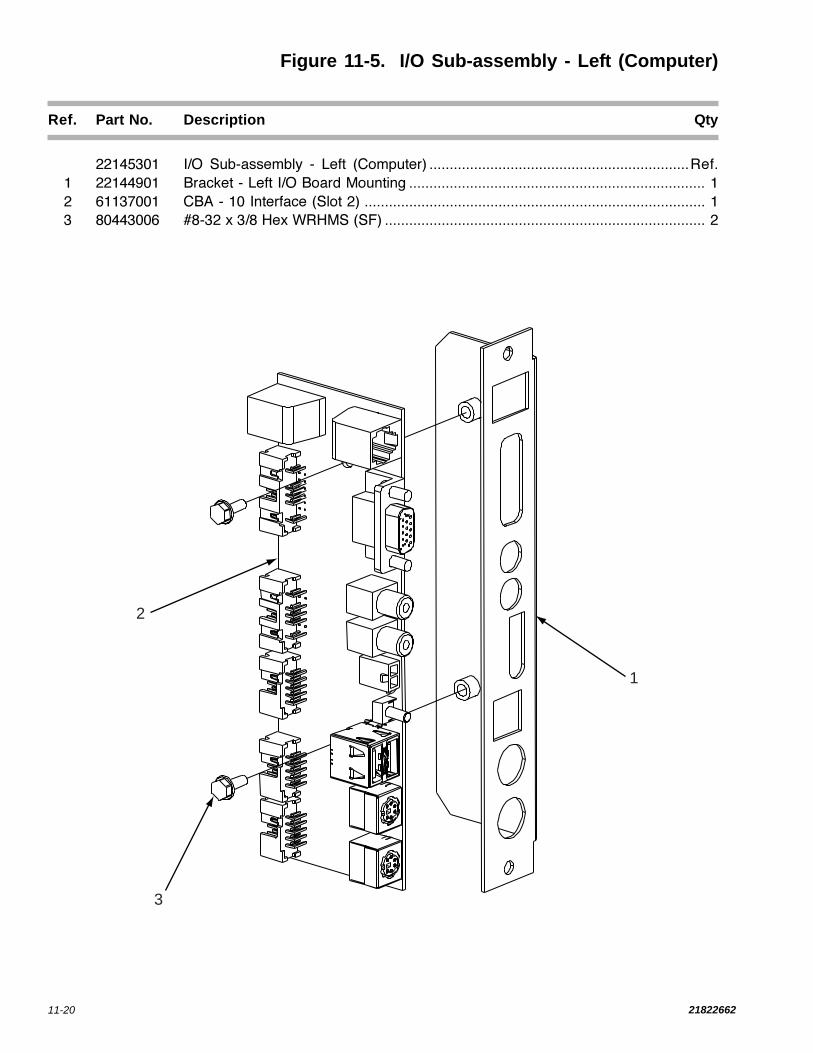
11-20 21822662
Figure 11-5. I/O Sub-assembly - Left (Computer)
Ref. Part No. Description Qty
22145301 I/O Sub-assembly - Left (Computer) ................................................................Ref.
1 22144901 Bracket - Left I/O Board Mounting ......................................................................... 1
2 61137001 CBA - 10 Interface (Slot 2) .................................................................................... 1
3 80443006 #8-32 x 3/8 Hex WRHMS (SF) ............................................................................... 2
1
2
3

11-2121822662
Figure 11-6. I/O Sub-assembly - Right (Computer)
Ref. Part No. Description Qty
22145401 I/O Sub-assembly - Right (Computer) .............................................................Ref.
1 22145001 Bracket - Right I/O Board Mounting ...................................................................... 1
2 61137001 CBA - 10 Interface (Slot 1) .................................................................................... 1
3 80443006 #8-32 x 3/8 Hex WRHMS (SF) ............................................................................... 3
1
2
3

11-22 21822662
Figure 11-7. Intermediate Board Sub-assembly
Ref. Part No. Description Qty
22150601 Intermediate Board Sub-assembly ..................................................................Ref.
1 22145101 Bracket - Board Mounting (Computer) ................................................................. 1
2 70500209 Spacer - Self-Retaining (#8 Nylon) ....................................................................... 4
3 34040201 CBA - Interconnect (Hard Dr/CC) ......................................................................... 1
4 80443008 #8-32 x 1/2 Hex WRHMS (SF) ............................................................................... 4
2
3
4
1

11-2321822662
Figure 11-8. Computer Drive Door Assembly
Ref. Part No. Description Qty
22144101 Computer Drive Door Assembly .....................................................................Ref.
1 22144801 Bracket - Drive Bay Mounting ............................................................................... 2
2 xxxxxxx #6-32 Screw (Supplied With Hard Drive Bay) ..................................................... 4
3 22144701 Hinge - Door ........................................................................................................... 1
4 80443004 #8-32 x 1/4 Hex WRHMS (SF) ............................................................................... 9
5 22144201 Door - Drive ........................................................................................................... 1
6 80321606 #4-40 x 1/4 Flat Head MS ...................................................................................... 4
7 22150801 Latch - Draw........................................................................................................... 2
8 87831600 #4-40 Hex Nut (CSZP) ........................................................................................... 4
9 22141702 Frame - Hard Drive ............................................................................................... 1
1
2
3
4
5
6 7 8 9

11-24 21822662
12
3
4
56
7
8
9
10
12
11
Figure 11-9. Power Supply Assembly
Ref. Part No. Description Qty
22145801 Power Supply Assembly ..................................................................................Ref.
1 22145901 Chassis - Power Supply ....................................................................................... 1
2 80443006 #8-32 x 3/8 Hex WRHMS (SF) ............................................................................. 12
3 30785702 Switch - Rocker (DPST) ........................................................................................ 1
4 80713010 #8-32 x 5/8 Hex WRHMS (SEMS) ......................................................................... 2
5 22118701 Power Inlet IEC 320 C-14 ...................................................................................... 1
6 21375902 Outlet - Convenience ............................................................................................ 2
7 70073609 Circuit Breaker (6 Amp) ........................................................................................ 2
8 87843000 #8-32 Keps Hex Nut ............................................................................................... 4
9 34038804 Harness Assembly - Power Supply (Only Connectors Shown) ........................ 1
10 22145801 Cover - Power Supply .......................................................................................... 1
11 40923401 CBA - Power Supply ............................................................................................. 1
12 22141301 Standoff .................................................................................................................. 4

11-2521822662
Figure 11-10. A/V Controller - 4 Channel
Ref. Part No. Description Qty
For 1000 Watt Studio Sound Only40917401 A/V Controller - 4 Channel .................................................................................. Ref.
1 40920701 Base Assembly - Preamp ....................................................................................... 1
2 61128802 CBA - A/V Controller (4 Channel) ........................................................................... 1
70500209 Spacer - Self-Retaining .......................................................................................... 1
80443008 #8-32 x 1/2 Hex WrHS (Swage Form) .................................................................... 2
3 34033701 Bracket - Card Guide .............................................................................................. 4
4 22137301 Guide - Card ........................................................................................................... 8
80443006 #8-32 x 3/8 Hex WrHMS......................................................................................... 8
5 61132801 Cover - Preamp ...................................................................................................... 1
80443006 #8-32 x 3/8 Hex WrHMS ........................................................................................ 4
CH1
CH2CH3
CH4
CH1 - CH2CH1 + CH2
CH3 - CH4CH3 + CH4
SIGNAL OUTPUTS
CH4 OUTPUT
CH3INVERTSIGNALOUTPUT
CH2OUTPUT
CH1INVERTSIGNALOUTPUT
CH1NON-INVERTSIGNAL
CH3NON-INVERTSIGNAL OUTPUT
AUX INPUT CHANNELS
1
2
3
4ACGNDGND
ACGNDPOWER
CH1INPUTCH2INPUT
CH3INPUTCH4INPUTEQUALIZEROUT
EQUALIZEROUT
LEFTRIGHT
LEFTRIGHT
LEFTRIGHT
AUXILLARY OUT
MONO C(BGM) INPUT
STEREO A(BGM) INPUTSTEREOMECHANISMINPUT
STEREO BINPUT
CHANNELS
RIGHT
ROWEMIC 3
ROWEMIC 1
ROWEMIC 2
ROWELINK
AUDIOSWITCH
AUDIOSWITCH
MUTE
ROWELINK
12
34
MUTE
MIC 1BALANCEUNBALANCEINPUT
MIC 2BALANCEUNBALANCEINPUT
MIC 3BALANCEUNBALANCEINPUT
VIDEOSWITCH
Extremely CoolAudio/VideoController
40917401
LEFT
1
2
3
4
5

11-26 21822662
Figure 11-11. 2 CHANNEL PREAMP
Ref. Part No. Description Qty
FOR 1000 WATT 2 CHANNEL ONLY61138701 2 Channel Preamp Assembly .......................................................................................... Ref.
1 61138601 Preamp Cover ..................................................................................................................... 1
2 40928701 Preamp Base ...................................................................................................................... 1
NOT SHOWN:21620706 Jumper Plug Assembly ......................................................................................................... 1
1
2

11-2721822662
Figure 11-12. Output Transformer Assembly
Ref. Part No. Description Qty
40832108 Output Transformer Assembly .......................................................................................... Ref.
1 61133101 Chassis - Audio Output ........................................................................................................ 1
2 40633503 Transformer - Output ............................................................................................................. 2
3 30426701 Binding Post Strip ................................................................................................................. 2
4 30426706 Binding Post Strip ................................................................................................................. 1
80442306 #6-32 x 3/8 Thread Form ...................................................................................................... 6
5 70233206 Bushing - Snap (Split) .......................................................................................................... 1
34033402 Harness Assembly - Output Transformer (not shown) ........................................................... 1
1
23
4
5
2 3

11-28 21822662
Figure 11-13. Rowelink Controller Assembly
Ref. Part No. Description Qty
40926001 Rowelink Controller Assembly ............................................................................ Ref.1 40925801 Base - Rowelink Controller ..................................................................................... 12 61135701 CBA - Rowelink Controller ...................................................................................... 13 80713008 #8-32 x 5/16 Hex WRHMS (SEMS)........................................................................ 84 80443008 #8-32 x 1/2 Hex WRHMS (SF) ............................................................................... 45 40925901 Cover - Rowelink Controller .................................................................................... 1
1
2
3
4
5

11-2921822662
Figure 11-14. Hanger Bracket Assembly
Ref. Part No. Description Qty
61114002 Hanger Bracket Assembly .................................................................................. Ref.1 87843700 #10-32 Hex Keps Nut ............................................................................................. 42 34015401 Standoff - Hanger ................................................................................................... 43 61114102 Hanger - Weld Assembly ........................................................................................ 14 89973724 #10-32 x 1 1/2 Carriage Bolt ................................................................................... 4
1
2
3
4

11-30 21822662
26704402 Phonograph paging system with Paging system not affected by A.V.C. All plug-in unit,hand held microphone complete with microphone and 50 foot microphone
cable.
26694703 Amplifier Accessory Kit Provides assess to auxiliary inputs and outputs of theNOTE: This kit will work with all preamplifier. Inputs will accept signals from most607925XX and 610237XX background music sources, such as tape players andpreamplifiers. AM/FM radios. Outputs are available to drive slave
amplifiers before or after volume control.
30632201 Remote Volume and Cancel This remote stereo volume control includes a cancelControl button. This kit does not include a cable. A 3 conduc-
tor cable is required.
30632209 Dual Remote Volume Control Controls volume of each channel separately. Does notinclude cable. A four conductor cable is required.
20819907 Remote Volume and Cancel This 3 conductor 50 foot cable connects a remoteControl Cable volume control to a phonograph.
20819908 Remote Volume and Cancel This 4 conductor 50 foot cable connects a remoteControl Cable volume control to a phonograph.
ACCESSORY EQUIPMENTFOR 2 CHANNEL PREAMP ONLY
Part No. Description Function


