Embed Size (px)
Citation preview
ENERGY STAR®
MULTIFAMILY HIGH RISE PROGRAM
Simulation Guidelines-Appendix G 90.1-2016
Version 1.0
December 2017
ENERGY STAR MFHR Simulation Guidelines Appendix G 2016 Page 2
Contents
1 Definitions ............................................................................................................................................. 4
2 Purpose and Scope ............................................................................................................................... 6
3 Simulation Methodology ...................................................................................................................... 7
3.1 General ............................................................................................................................................. 7
3.2 Required energy simulations ............................................................................................................ 7
3.3 Modeled end uses............................................................................................................................. 7
3.4 Approved Simulation Tools ............................................................................................................... 8
3.5 Project Boundary .............................................................................................................................. 8
3.6 Projects involving multiple buildings ................................................................................................ 8
3.7 Schedules .......................................................................................................................................... 8
3.8 Exceptional Calculations ................................................................................................................... 9
3.9 Excluded Systems ............................................................................................................................ 10
3.10 Modeling Future Systems and Components .................................................................................. 10
3.11 Renovation Projects ........................................................................................................................ 11
4 Energy Rates ....................................................................................................................................... 11
5 Performance Rating Calculations ........................................................................................................ 11
6 System - Specific Requirements .......................................................................................................... 12
6.1 Building Envelope ........................................................................................................................... 12
6.1.1 Baseline Design ................................................................................................................... 12
6.1.2 Proposed Design Model ...................................................................................................... 13
6.1.3 Partially glazed doors .......................................................................................................... 15
6.1.4 Shading ............................................................................................................................... 16
6.1.5 F-factor ................................................................................................................................ 16
6.2 Infiltration ....................................................................................................................................... 16
6.3 Interior Lighting .............................................................................................................................. 17
6.3.1 Lighting Schedule ................................................................................................................ 17
6.3.2 Baseline Lighting ................................................................................................................. 18
6.3.3 Proposed Lighting ............................................................................................................... 19
6.4 Exterior Lighting .............................................................................................................................. 21
6.4.1 General................................................................................................................................ 21
6.4.2 Schedule .............................................................................................................................. 22
ENERGY STAR MFHR Simulation Guidelines Appendix G 2016 Page 3
6.4.3 Lighting Power .................................................................................................................... 22
6.5 Heating, Ventilation, and Air Conditioning ..................................................................................... 23
6.5.1 Thermostat Setpoints ......................................................................................................... 23
6.5.2 Space conditioning (Table G3.1 No. 1 b) ............................................................................. 23
6.5.3 Baseline HVAC System Type ............................................................................................... 23
6.5.4 Baseline HVAC System Capacity ......................................................................................... 24
6.5.5 Baseline HVAC DX System Efficiency .................................................................................. 24
6.5.6 Baseline Boiler and Furnace Efficiency ............................................................................... 25
6.5.7 Baseline PTHP Heating Control ........................................................................................... 25
6.5.8 Performance Curves ........................................................................................................... 25
6.5.9 Proposed HVAC System Capacity and Efficiency ................................................................ 26
6.5.10 HVAC Fan System Energy .................................................................................................... 27
6.5.11 HVAC Distribution System .................................................................................................. 29
6.5.12 Mechanical Ventilation ....................................................................................................... 30
6.5.13 District Systems ................................................................................................................... 32
6.6 Other Heating and Ventilation Systems ......................................................................................... 32
6.6.1 Systems for snow/Ice melt, pipe freeze protection, and garage heating .......................... 32
6.6.2 Ventilation Control in Garages............................................................................................ 32
6.7 Domestic (Service) Water Heating (Appendix G Table G3.1 No. 11) .............................................. 34
6.7.1 Equipment Type and Efficiency .......................................................................................... 34
6.7.2 Hot Water Demand. ............................................................................................................ 34
6.7.3 Domestic Hot Water Distribution System........................................................................... 36
6.8 Receptacles and other plug loads (Appendix G Table G3.1, Section 12) ........................................ 36
6.9 Elevators ......................................................................................................................................... 38
6.10 Other Loads ..................................................................................................................................... 39
6.10.1 Non-HVAC Motors 1 HP or larger ....................................................................................... 39
6.11 Water Savings (Optional) ................................................................................................................ 40
APPENDIX A: Referenced Standards and Data Sources (Informative) ....................................................... 42
ENERGY STAR MFHR Simulation Guidelines Appendix G 2016 Page 4
1 Definitions ASHRAE 90.1-2016 (ASHRAE 90.1, 90.1): energy standard for buildings, except low-rise residential
buildings. Minimum requirements for the energy-efficient design of multifamily buildings over
three stories above grade are included within this standard.
ASHRAE 90.1-2016 Appendix G (Appendix G): This appendix offers an alternative path for
minimum standard compliance, and allows quantifying performance of projects that exceed the
requirements of the standard.
As-Built: conditions observed and measured in the completed building. The As-Built energy
model must represent the actual observed and measured conditions in the constructed building,
except where directed otherwise in this document.
Baseline Building Design (baseline design, baseline): a computer representation of a hypothetical
design based on the Proposed Design. This representation is used as the basis for calculating the
baseline building performance for rating above-standard design or when using the performance
rating method as an alternative path for minimum standard compliance.
Baseline Building Performance: the annual energy use of the Baseline Building Design, expressed
in the units of energy cost or alternate units if EPA guidance approves them for use.
Common Space: any spaces within a building that serves a function in support of the residential
part of the building that is not part of a dwelling unit. This includes spaces used by residents, such
as corridors, stairs, lobbies, laundry rooms, exercise rooms, residential recreation rooms, parking
used exclusively by residents, building staff, and their guests. This also includes offices used by
building management, administration or maintenance and all special use areas located in the
building to serve and support the residents such as day-care facilities, gyms, dining halls, etc.
Design Team: group of professionals responsible for the final design of a building including, but
not limited to: the developer, the general contractor, the architect, and design engineers.
Dwelling Unit: a single unit providing complete independent living facilities for one or more
persons, including permanent provisions for living, sleeping, eating, cooking, and sanitation.
Dwelling Unit Mechanical Ventilation: A mechanical exhaust system, supply system, or
combination thereof that provides each dwelling unit with outdoor air each hour. Projects with
specified ventilation rates in excess of the minimum required in ASHRAE 62.2-2013 are considered
over-ventilated, and are subject to over-ventilation penalty as described in Section 6.5.12 of this
document.
Energy Neutral: systems and components in the Proposed Design that are modeled to avoid a
direct penalty or credit in the Performance Rating Calculations.
a) Energy neutral Unregulated systems and components must be modeled the same in the
baseline and proposed design.
b) Energy neutral Regulated systems and components must be modeled as follows:
ENERGY STAR MFHR Simulation Guidelines Appendix G 2016 Page 5
Baseline must be modeled based on the applicable requirements of Appendix G. If not
prescribed in the Appendix G, the baseline must reflect requirements in Section 5 to 10 of the
reference edition of 90.1.
Proposed Design must be modeled as meeting applicable requirements of the reference
edition of 90.1.
In-Unit: term used to describe features in the building that are located within the dwelling units.
For example, “in-unit lighting” is used to reference lighting located within the apartments.
Local Mechanical Exhaust: An intermittent or continuously operating exhaust fan that removes
air from a conditioned space, such as the dwelling unit’s bathrooms and kitchen, and discharges
to the outside. A bathroom is any room containing a bathtub, a shower, a spa, or similar source of
moisture. A kitchen is any space containing cooking appliances.
Nonresidential: spaces in mixed-use buildings other than residential or common space, such as
commercial retail or office spaces that do not serve and support the residents.
Performance Path Calculator: set of spreadsheet calculators provided by the Program to assist
energy modelers in generating certain specific data inputs needed to complete the energy model
for the Baseline Building Design and Proposed Design as referenced in this document, as well as
summarize modeling results. “Performance Path Calculator_AppG2016” must be used in
conjunction with these Simulation Guidelines.
Performance Rating: percent reduction in the baseline building performance compared to the
proposed building performance or as-built performance across all end-uses, normalized to
represent improvement relative to the reference edition of 90.1.
Performance Target: minimum Performance Rating required to earn the ENERGY STAR. Proposed
Design and As-Built must achieve the set margin of improvement over the reference edition of
90.1 to be eligible for the ENERGY STAR. Energy savings associated with on-site power generation,
including cogeneration, photovoltaics, or wind turbines, may not contribute to meeting the
Performance Target, but may be used to exceed it.
Prerequisites: minimum program standards set by EPA to restrict the ability of the design team to
make performance trade-offs that would allow individual building components to fall below
minimum acceptable standards. A Prerequisites Checklist is provided in the Testing and
Verification Worksheets.
Proposed Building Performance: the annual energy use of the Proposed Design, expressed in the
units of energy cost or alternate units if EPA guidance approves them for use.
Proposed Design: a computer representation of the actual proposed building design or portion
thereof used as the basis for calculating the design energy consumption.
Regulated Energy Use: energy used by building systems and components with requirements
prescribed in ASHRAE 90.1 Sections 5 through 10. This includes energy used for interior lighting
including lighting inside dwelling units, exterior lighting, Service Hot Water (SHW) heating, space
ENERGY STAR MFHR Simulation Guidelines Appendix G 2016 Page 6
heating, humidification, dehumidification, mechanical cooling, heat rejection, cooling towers,
HVAC supply, return and exhaust fans, heat recovery fans and wheel energy, hydronic pumping
including SHW recirculation and booster pumps, elevators, in-building transformers, and other
building systems, components, and processes with requirements prescribed in Sections 5 through
10.
Reference edition of 90.1: the version of ASHRAE Standard 90.1 that is used as the basis of the
Performance Rating. For example, as of October 2016, New York energy code is based on the
ASHRAE Standard 90.1-2013. Thus, ASHRAE Standard 90.1-2013 is the reference edition of 90.1 for
projects in New York that are governed by this code, and these projects must achieve the
Performance Rating of 15% or higher over 90.1-2013 to meet the ENERGY STAR MFHR
performance target.
Residential: spaces in buildings used primarily for living and sleeping. Residential spaces include,
but are not limited to, dwelling units or sleeping units.
Residential-associated: see common space
Sleeping Units: A room or space in which people sleep, which can also include permanent
provisions for living, eating, and either sanitation or kitchen facilities but not both. Such rooms
and spaces that are also part of a dwelling unit are not sleeping units.
Ventilation: the process of supplying outdoor air to or removing outdoor air from a space by
mechanical means.
Unregulated Energy Use: energy used by building systems and components that is not regulated
energy use, such as energy used by kitchen and laundry appliances, and miscellaneous consumer
electronics.
2 Purpose and Scope These Simulation Guidelines (SG) contain the methodology for calculating a Performance Rating
for multifamily buildings participating in the EPA’s ENERGY STAR Multifamily High Rise Program
(“Program”) and following the Performance Rating Method of ASHRAE 90.1-2016 Appendix G.
These SG must be used as a supplement to ASHRAE 90.1-2016 Appendix G. The ASHRAE Standard
90.1 applies to a wide range of building types, and thus does not address certain characteristics
commonly found in high rise multifamily buildings with sufficient specificity to ensure that energy
modeling results are consistent from one energy modeler to the next. This document is designed
to address these issues, and to meet the following objectives:
a. Ensure a consistent simulation methodology from building to building and from energy
modeler to energy modeler.
b. Ensure a consistent approach to simulating components that are not included in Appendix G,
or included without the level of detail needed to support the simulation process.
c. Provide consistent interpretation for the “grey areas” in the Appendix G
d. Re-iterate and clarify the areas where simulation mistakes are often made
ENERGY STAR MFHR Simulation Guidelines Appendix G 2016 Page 7
e. Address areas that Appendix G leaves for the “rating authority” to decide. The “rating
authority” is the EPA.
3 Simulation Methodology
3.1 General
Buildings shall be simulated following ASHRAE 90.1-2016 Appendix G Performance Rating Method
(PRM, Appendix G) and as described in this document.
Exception: Compliance with Appendix G Section G.1.2.1 is not required.
Addenda to ASHRAE 90.1-2016 will be reviewed by the EPA. If EPA issues guidance that the
addenda may be used, it must be explicitly referenced in the submittals and followed in its
entirety. The guidance document will specify whether one addendum or several addenda may be
used without having to use all the addenda.
The Baseline Building Design and Proposed Design shall be based on the final design of the
building, not the initial or preliminary design that was received by the energy modeler from the
design team. Thus, both the Baseline Building Design and Proposed Design may require changes
until all the design parameters are finalized.
3.2 Required energy simulations
The baseline design model shall follow requirements of Appendix G and Simulation Guidelines.
The proposed design must be modeled as described in Appendix G, and reflect the proposed
building components, except where otherwise specified in this document. The proposed design
must comply with the prerequisites of this Program and the applicable state and local codes.
As-Built model must be based on the proposed design model updated to reflect the actual
building components, as verified or measured during site inspections. At the completion of the construction, these same guidelines must be used to calculate the Performance Rating for the As-
Built model, by substituting “As-Built” where you find “Proposed Design”. Some components that
are not required to reflect As-Built conditions within the energy model are specified in the
relevant sections below. Although some required measurements are not incorporated in the energy model, such as total in-unit duct leakage tests, they do have restrictions as described in the prerequisites.
3.3 Modeled end uses
a. Baseline and proposed design models shall include all the energy uses within and
associated with the building. This includes
loads that are not regulated by ASHRAE
90.1, except where explicitly required
otherwise in the Simulation Guidelines.
b. Baseline model shall not include end uses
that do not exist in the proposed building.
EXAMPLE 3-1 - Unlit Parking Lot
Q. Building design includes a parking lot that is not lit. What lighting power allowance can be used in the baseline model for the parking lot?
A. Since the parking lot in the proposed design is not lit, the parking lot lighting power allowance cannot be added to the baseline energy consumption.
ENERGY STAR MFHR Simulation Guidelines Appendix G 2016 Page 8
Exception: Space cooling must be modeled in all conditioned spaces per Appendix G Table G3.1-
1.b whether or not it is specified, except in spaces designed with heating only systems serving
storage rooms, stairwells, vestibules, electrical/mechanical rooms, and restrooms not exhausting
or transferring air from mechanically cooled thermal zones in the proposed design.
EXAMPLE 3-2 Spaces with No Cooling Specified
Q. A multifamily building in Climate Zone 4A includes dwelling units, common corridors, stairwells, tenant storage, and mechanical/utility rooms. No cooling is specified for any of the spaces. Should cooling be included in the baseline and the proposed design model?
A. Based on the definition of space in ASHRAE 90.1 Section 3 and heating output of the equipment specified in the proposed design, the dwelling units, corridors, and tenant storage are conditioned spaces, and stairwells and mechanical/utility rooms are semi-heated. Thus, cooling must be modeled as follows in both the baseline and proposed design:
- Dwelling units and corridors must be modeled with cooling.
- Tenant storage is subject to Appendix G Exception to G3.1-1.b, and must be modeled with no cooling.
- Stairwells and mechanical/utility rooms are not conditioned spaces and must also be modeled with no cooling.
Cooling system efficiency must be modeled as described in SG Section 6.5.5.
3.4 Approved Simulation Tools
Simulation software must comply with the requirements outlined in Appendix G Section G2.2.
Examples of allowed tools include eQUEST, DOE2.1, Energy Plus, Carrier HAP, Open Studio, and
Trane Trace 700. Other software tools may be approved on a case by case basis.
3.5 Project Boundary
The models shall include all dwelling units and common spaces in the building. Other
nonresidential areas such as retail stores or offices open to the general public and unrelated to
the building’s residential function may be included or excluded from the simulations at the
discretion of the energy modeler. If included, energy savings may only be modeled for a measure
if it meets the relevant Program prerequisites. Otherwise, they must be modeled energy neutral.
If excluded, the building will not be eligible to receive the Designed to Earn ENERGY STAR logo
after approval of the Proposed Design Submittal., but will still be eligible for ENERGY STAR MFHR
certification.
3.6 Projects involving multiple buildings
Separate Baseline Building Design and Proposed Design models shall be created for each non-
identical building in the project. The Performance Rating shall be calculated individually for each
such building.
3.7 Schedules
The models must include the schedules described in this document, or approved equivalent. All
schedules that differ from the ones specified in the Simulation Guidelines shall be documented
and submitted to EPA for approval.
ENERGY STAR MFHR Simulation Guidelines Appendix G 2016 Page 9
The same schedules must be used in both the Baseline Building Design and Proposed Design
unless explicitly allowed otherwise in Appendix G or this document. Any difference in the
schedules must be documented.
3.8 Exceptional Calculations
If an approved simulation tool used for the project does not have the capability to calculate
energy usage and/or savings for a design feature allowed by Appendix G and SG, supplemental
calculations may be used. All such calculations must be documented following requirements of
90.1 Section G2.5 summarized below:
a. Step-by-step documentation of the Exceptional Calculation Method performed detailed enough to reproduce the results;
b. Copies of all spreadsheets used to perform the calculations; c. A sensitivity analysis of energy consumption when each of the input parameters is varied
from half to double the value assumed; d. If the design feature in the exceptional calculations is related to HVAC, then the
calculations shall be performed on a time step basis consistent with the simulation program used;
e. The energy use with and without the Exceptional Calculation Method must be submitted.
The total savings from the Exceptional Calculations must not account for more than half of the
documented improvement over code. Exceptional calculations not described in this document
shall be submitted to the EPA for review and approval.
ENERGY STAR MFHR Simulation Guidelines Appendix G 2016 Page 10
3.9 Excluded Systems
Energy savings associated with on-site power generation, including cogeneration with the
associated waste heat recovery, photovoltaics, or wind turbines, may not contribute to meeting
the Performance Target, but may be used to exceed it. To demonstrate achievement of the
Performance Target, Proposed Building Performance must be determined without any credit for
reduced annual energy costs from on-site power generation. The specified backup systems shall
be modeled in place of waste heat recovery as applicable. If backup system is not specified, or
does not have the sufficient capacity, the systems modeled in place of waste heat must be
modeled as energy neutral.
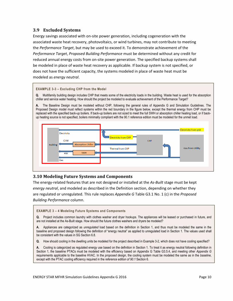
EXAMPLE 3-3 – Excluding CHP from the Model
Q. Multifamily building design includes CHP that meets some of the electricity loads in the building. Waste heat is used for the absorption chiller and service water heating. How should the project be modeled to evaluate achievement of the Performance Target?
A. The Baseline Design must be modeled without CHP, following the general rules of Appendix G and Simulation Guidelines. The Proposed Design model must reflect systems within the red boundary in the figure below, except the thermal energy from CHP must be replaced with the specified back-up boilers. If back-up boilers are not sized to meet the full SWH or absorption chiller heating load, or if back-up heating source is not specified, boilers minimally compliant with the 90.1 reference edition must be modeled for the unmet load.
3.10 Modeling Future Systems and Components
The energy-related features that are not designed or installed at the As-Built stage must be kept
energy neutral, and modeled as described in the Definition section, depending on whether they
are regulated or unregulated. This rule replaces Appendix G Table G3.1 No. 1 (c) in the Proposed
Building Performance column.
EXAMPLE 3 – 4 Modeling Future Systems and Components
Q. Project includes common laundry with clothes washer and dryer hookups. The appliances will be leased or purchased in future, and are not installed at the As-Built stage. How should the future clothes washers and dryers be modeled?
A. Appliances are categorized as unregulated load based on the definition in Section 1, and thus must be modeled the same in the baseline and proposed design following the definition of “energy neutral” as applied to unregulated load in Section 1. The values used shall be consistent with the values in SG Section 6.8.
Q. How should cooling in the dwelling units be modeled for the project described in Example 3-2, which does not have cooling specified?
A. Cooling is categorized as regulated energy use based on the definition in Section 1. To treat it as energy neutral following definition in Section 1, the baseline PTACs must be modeled with the efficiency based on Appendix G Table G3.5.4, and meeting other Appendix G requirements applicable to the baseline HVAC. In the proposed design, the cooling system must be modeled the same as in the baseline, except with the PTAC cooling efficiency required in the reference edition of 90.1 Section 6.
ENERGY STAR MFHR Simulation Guidelines Appendix G 2016 Page 11
3.11 Renovation Projects
The baseline design for renovation projects must be modeled the same as for new construction
and additions, following Appendix G Table G3.1 No. 2 Baseline Building Performance column,
unless allowed otherwise in this document.
EXAMPLE 3 – 5 Modeling Renovation Projects
Q. Project includes a major renovation of a school that is converted to an apartment building. The scope of the renovation includes added roof insulation, window replacement, and all new interior lighting and mechanical systems. Exterior walls and exterior lighting remain as is. How should the baseline and proposed design be modeled?
A. All baseline systems must be modeled the same as for the new construction project. The proposed design model must reflect the specified roof, windows, interior lighting, and mechanical systems, and the existing exterior lighting and exterior walls. The project’s performance rating will be negatively affected by excluding exterior lighting and exterior walls from the scope of retrofit.
4 Energy Rates Unless provided otherwise by EPA or its designated agent, per Appendix G, Section G2.4.2, use
either actual rates for purchased energy or state average energy prices published by DOE’s Energy
Information Administration in energy simulations of Baseline Building Design, Proposed Design,
and As-Built (www.eia.doe.gov). The selected source must be used for all fuels in the project. The
rate schedule used in the Baseline Building Design must be the same as in simulations of the
Proposed Design and As-Built.
If actual rate schedules and pricing, according to the rate class that will most likely be assigned to
the property are used, supporting documentation must be provided showing monthly pricing for
12 consecutive months.
Performance credit for the reduced energy cost may be claimed only if the cost reduction is due
to the reduced energy consumption or demand. Following this rule, savings associated with sub-
metering shall not be included in the Performance Rating.
5 Performance Rating Calculations The Performance Rating is calculated as described in this section. The calculation is incorporated
into the Performance Path Calculator_AppG2016, and is provided for reference.
Performance Rating = 100∗ (PCIt−PCI)/PCIt
PCIt = (BBUEC + (BPF x BBREC))/BBP
PCI = PBP/BBP
where:
PCI = Performance Cost Index
PCIt= Performance Cost Index Target
BBP = Baseline Building Performance
PBP= Proposed Building Performance
BBREC = Baseline Building Regulated Energy Cost. The portion of the annual energy cost of a
ENERGY STAR MFHR Simulation Guidelines Appendix G 2016 Page 12
baseline building design that is due to regulated energy use, calculated by multiplying
the total energy cost by the ratio of regulated energy use to total energy use for each fuel type.
BBUEC = Baseline Building Unregulated Energy Cost. The portion of the annual energy cost of a
baseline building design that is due to unregulated energy use, calculated by
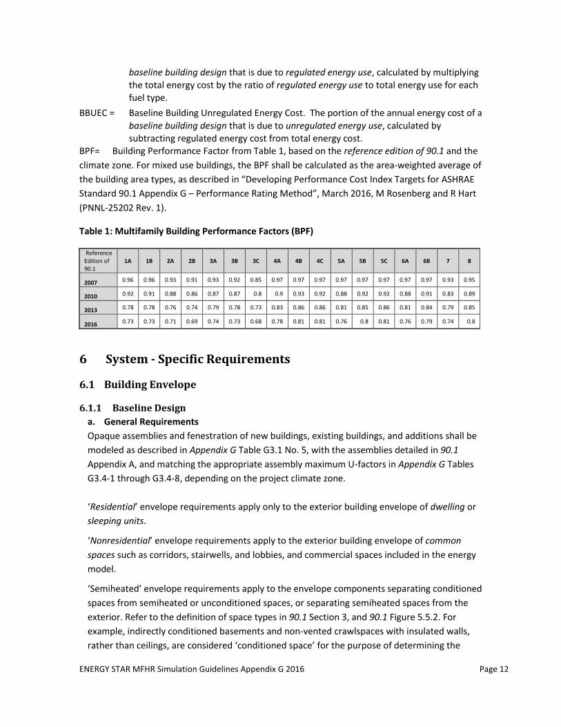
subtracting regulated energy cost from total energy cost. BPF= Building Performance Factor from Table 1, based on the reference edition of 90.1 and the
climate zone. For mixed use buildings, the BPF shall be calculated as the area-weighted average of
the building area types, as described in “Developing Performance Cost Index Targets for ASHRAE
Standard 90.1 Appendix G – Performance Rating Method”, March 2016, M Rosenberg and R Hart
(PNNL-25202 Rev. 1).
Table 1: Multifamily Building Performance Factors (BPF)
Reference Edition of 90.1
1A 1B 2A 2B 3A 3B 3C 4A 4B 4C 5A 5B 5C 6A 6B 7 8
2007 0.96 0.96 0.93 0.91 0.93 0.92 0.85 0.97 0.97 0.97 0.97 0.97 0.97 0.97 0.97 0.93 0.95
2010 0.92 0.91 0.88 0.86 0.87 0.87 0.8 0.9 0.93 0.92 0.88 0.92 0.92 0.88 0.91 0.83 0.89
2013 0.78 0.78 0.76 0.74 0.79 0.78 0.73 0.83 0.86 0.86 0.81 0.85 0.86 0.81 0.84 0.79 0.85
2016 0.73 0.73 0.71 0.69 0.74 0.73 0.68 0.78 0.81 0.81 0.76 0.8 0.81 0.76 0.79 0.74 0.8
6 System - Specific Requirements
6.1 Building Envelope
6.1.1 Baseline Design
a. General Requirements
Opaque assemblies and fenestration of new buildings, existing buildings, and additions shall be
modeled as described in Appendix G Table G3.1 No. 5, with the assemblies detailed in 90.1
Appendix A, and matching the appropriate assembly maximum U-factors in Appendix G Tables
G3.4-1 through G3.4-8, depending on the project climate zone.
‘Residential’ envelope requirements apply only to the exterior building envelope of dwelling or
sleeping units.
‘Nonresidential’ envelope requirements apply to the exterior building envelope of common
spaces such as corridors, stairwells, and lobbies, and commercial spaces included in the energy
model.
‘Semiheated’ envelope requirements apply to the envelope components separating conditioned
spaces from semiheated or unconditioned spaces, or separating semiheated spaces from the
exterior. Refer to the definition of space types in 90.1 Section 3, and 90.1 Figure 5.5.2. For
example, indirectly conditioned basements and non-vented crawlspaces with insulated walls,
rather than ceilings, are considered ‘conditioned space’ for the purpose of determining the
ENERGY STAR MFHR Simulation Guidelines Appendix G 2016 Page 13
envelope baseline, and therefore the ‘nonresidential’ requirements apply instead of
‘semiheated’.
b. Spandrel assemblies Spandrel areas of curtain wall systems are opaque assemblies, and must be modeled in the
baseline as steel-framed walls with the appropriate U-factor.
c. Through-wall PTAC/PTHP sleeves
Thermal properties of through-wall PTAC/PTHP sleeves and penetrations must not be modeled
in the Baseline Design.
d. Fenestration area of the major renovation projects
The fenestration area shall equal the existing fenestration area prior to the proposed work and
shall be distributed on each face of the building in the same proportions as the existing building,
based on Appendix G Table G3.1 No. 5 (c), Baseline Building Performance column.
e. Orientation
The baseline for renovations and additions must reflect the actual building orientation. Baseline
orientation for new construction projects must be as described in Appendix G Table G3.1 No. 5
(a), Baseline Building Performance column.
6.1.2 Proposed Design Model
6.1.2.1 Thermal Bridging
a. Framing members
Thermal properties of framing, including but not
limited to steel-framed assemblies, must be
determined following ASHRAE 90.1 Appendix A to
capture thermal bridging.
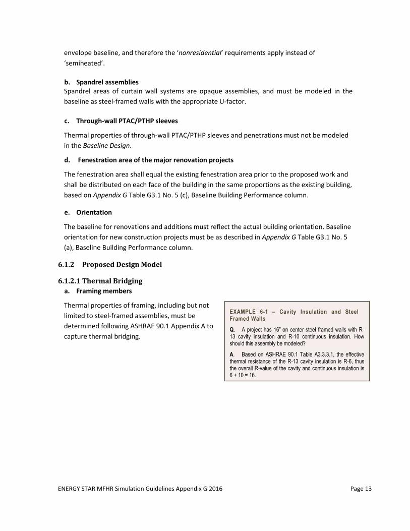
EXAMPLE 6-1 – Cavity Insulation and Steel Framed Walls
Q. A project has 16” on center steel framed walls with R-13 cavity insulation and R-10 continuous insulation. How should this assembly be modeled?
A. Based on ASHRAE 90.1 Table A3.3.3.1, the effective thermal resistance of the R-13 cavity insulation is R-6, thus the overall R-value of the cavity and continuous insulation is 6 + 10 = 16.
ENERGY STAR MFHR Simulation Guidelines Appendix G 2016 Page 14
b. Shelf Angles
The Proposed Design model must account for thermal bridging through portions of the wall
assembly where shelf angles or other continuous metal fastened to the wall are used.
Where those conditions exist, the insulation cannot contribute to the assembly U-factor for
those areas. An overall U-factor shall be calculated based on an area weighted average of
the thermal properties.
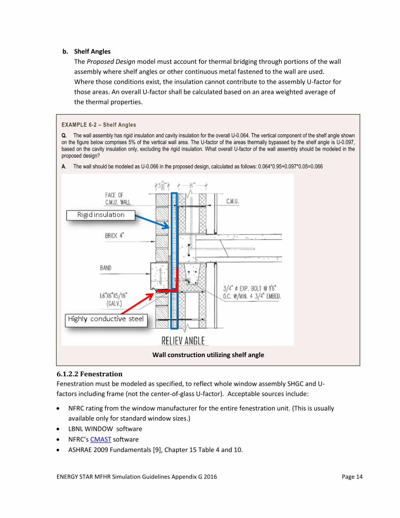
EXAMPLE 6-2 – Shelf Angles
Q. The wall assembly has rigid insulation and cavity insulation for the overall U-0.064. The vertical component of the shelf angle shown on the figure below comprises 5% of the vertical wall area. The U-factor of the areas thermally bypassed by the shelf angle is U-0.097, based on the cavity insulation only, excluding the rigid insulation. What overall U-factor of the wall assembly should be modeled in the proposed design?
A. The wall should be modeled as U-0.066 in the proposed design, calculated as follows: 0.064*0.95+0.097*0.05=0.066
Wall construction utilizing shelf angle
6.1.2.2 Fenestration
Fenestration must be modeled as specified, to reflect whole window assembly SHGC and U-
factors including frame (not the center-of-glass U-factor). Acceptable sources include:
NFRC rating from the window manufacturer for the entire fenestration unit. (This is usually
available only for standard window sizes.)
LBNL WINDOW software
NFRC’s CMAST software
ASHRAE 2009 Fundamentals [9], Chapter 15 Table 4 and 10.
ENERGY STAR MFHR Simulation Guidelines Appendix G 2016 Page 15
Certification provided by the installer or supplier listing the assembly U-factor and SHGC can
be used in lieu of NFRC labels, provided that they comply with the fenestration rating
requirements in Section 5.8.2 of the reference version of 90.1.
6.1.2.3 HVAC Penetrations
Through-wall AC sleeves and PTAC/PTHP penetrations must be modeled in the Proposed Design
with a U-factor of 0.5. Any R-value associated with an insulated cover shall not be included in the
model.
6.1.2.4 Unique envelope assemblies
Unique envelope assemblies such as projecting balconies, perimeter edges of intermediate floor
slabs, concrete floor beams over parking garages, and roof parapets, shall be separately modeled
in the Proposed Design, per Appendix G Table G3.1, No. 5 (a). A weighted average of the U-factors
of these assemblies is acceptable in the simulation. Projected balconies and perimeter edges of
intermediate floor slabs are considered to be a wall, per wall definition in Section 3 of 90.1, and
shall be modeled in the Baseline Building Design with the same U-factor and construction as
exterior walls.
6.1.3 Partially glazed doors
In the proposed design, the door U-factor and SHGC shall be modeled as per the NFRC label for
the door specified in the final design.
Doors that are more than one-half glass:
I. The entire door area shall be counted as vertical fenestration when calculating the
vertical fenestration-to-wall ratio.
II. The door shall be modeled as a single fenestration unit in both the Baseline Building
Design and Proposed Design.
III. The door U-factor and SHGC in the Baseline Building Design shall be determined based on
requirements for baseline vertical fenestration in Appendix G Tables G3.4-1 to G3.4-8 for
the applicable climate zone.
Doors that have glazing area of 50% or less:
I. Only the glazed portion of the door shall be included when calculating the vertical
fenestration-to-wall ratio.
II. Use one of the following options to model the door:
Model the entire door as opaque in the Baseline Building Design and Proposed
Design. The baseline door U-factor shall be modeled based on the Appendix G Tables
G3.4-1 to G3.4-8 requirements for opaque doors of appropriate type1.
Model the Baseline Building Design with a door of identical distribution of
opaque/glazed area to the proposed door and apply the requirements in Appendix G
1 The intent of this procedure is to simplify the modeling requirements for doors with less than 50% glazing area and not to create an energy penalty in the analysis for doors with less than 50% glazing area.
ENERGY STAR MFHR Simulation Guidelines Appendix G 2016 Page 16
Tables G3.4-1 to G3.4-8 for opaque doors of appropriate type to the opaque area, and
the fenestration U-factor and SHGC to the glazing area.
6.1.4 Shading
a. Automatically-controlled fenestration shades or blinds and permanent shading devices that
are part of the building, including but not limited to side fins, overhangs, and balconies,
must be modeled in the proposed design, and not modeled in the baseline.
b. Manual shading such as blinds or shades must not be modeled in either the baseline or
proposed design.
c. Shading by the adjacent structures and terrains must be included in both the baseline and
proposed design models, as described in Appendix G Table G3.1 No. 14.
6.1.5 F-factor
If the energy modeling software tool does not allow input of the perimeter heat loss factor (F-
factor), then the slab-on-grade construction that corresponds to the F-factor shall be modeled as
is appropriate for the software tool being used. If the slab-on-grade insulation in the Proposed
Design is a permitted method, as shown on Figure 5-S of the ASHRAE 90.1-2013 User’s Manual,
model slab-on-grade as energy neutral. If the slab-on-grade insulation is not a permitted method,
model as uninsulated in the Proposed Design, and based on the requirements in Appendix G Table
G3.4.1 to G3.4.8 in the baseline.
6.2 Infiltration
Infiltration rates must be modeled in the baseline and proposed design as described in Appendix G
Table G3.1 No. 5 (b), and must be calculated following Appendix G Section G3.1.1.4. Lower
infiltration may be modeled in the proposed design based upon the anticipated air leakage test
results or maximum air leakage allowed by the Program, per exception to Appendix G Table G3.1
No. 5 (b), Proposed Building Performance column. The infiltration rate in the As-Built model shall
reflect the air leakage testing results of a sample of individual apartments (compartmentalization
testing), or whole building air leakage testing. If compartmentalization testing results are used,
infiltration rate for the entire building shall be modeled based on the highest
compartmentalization test result (i.e. the leakiest) of all units subject to testing.
Exception: Each unit subject to testing is permitted to be modeled with their actual tested rate.
If the energy modeling software supports multiple infiltration algorithms, the same method must
be used in the Baseline Building Design and Proposed Design. Infiltration rate must be modeled at
100% (i.e. with the schedule fraction of 1) during all hours of the year.
ENERGY STAR MFHR Simulation Guidelines Appendix G 2016 Page 17
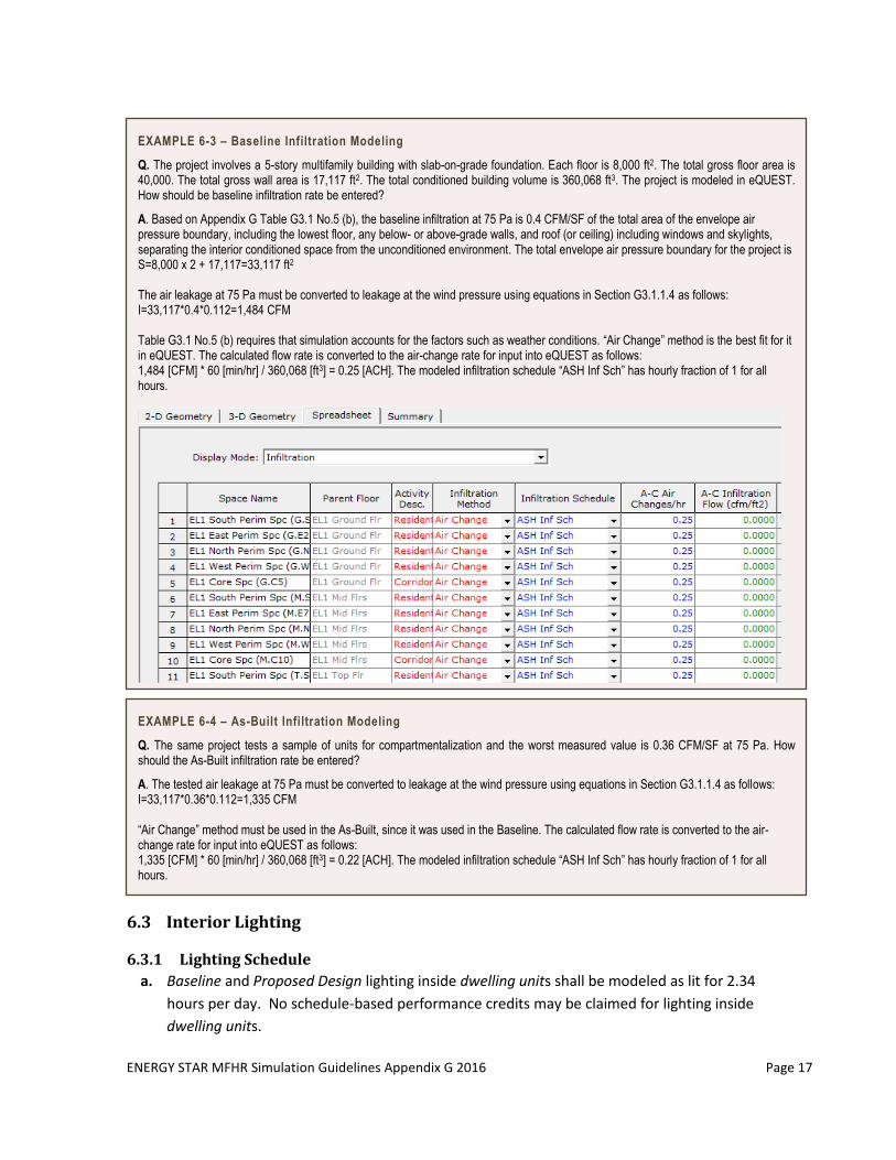
EXAMPLE 6-3 – Baseline Infiltration Modeling
Q. The project involves a 5-story multifamily building with slab-on-grade foundation. Each floor is 8,000 ft2. The total gross floor area is 40,000. The total gross wall area is 17,117 ft2. The total conditioned building volume is 360,068 ft3. The project is modeled in eQUEST. How should be baseline infiltration rate be entered?
A. Based on Appendix G Table G3.1 No.5 (b), the baseline infiltration at 75 Pa is 0.4 CFM/SF of the total area of the envelope air pressure boundary, including the lowest floor, any below- or above-grade walls, and roof (or ceiling) including windows and skylights, separating the interior conditioned space from the unconditioned environment. The total envelope air pressure boundary for the project is S=8,000 x 2 + 17,117=33,117 ft2 The air leakage at 75 Pa must be converted to leakage at the wind pressure using equations in Section G3.1.1.4 as follows: I=33,117*0.4*0.112=1,484 CFM Table G3.1 No.5 (b) requires that simulation accounts for the factors such as weather conditions. “Air Change” method is the best fit for it in eQUEST. The calculated flow rate is converted to the air-change rate for input into eQUEST as follows: 1,484 [CFM] * 60 [min/hr] / 360,068 [ft3] = 0.25 [ACH]. The modeled infiltration schedule “ASH Inf Sch” has hourly fraction of 1 for all hours.
:
.
EXAMPLE 6-4 – As-Built Infiltration Modeling
Q. The same project tests a sample of units for compartmentalization and the worst measured value is 0.36 CFM/SF at 75 Pa. How should the As-Built infiltration rate be entered?
A. The tested air leakage at 75 Pa must be converted to leakage at the wind pressure using equations in Section G3.1.1.4 as follows: I=33,117*0.36*0.112=1,335 CFM “Air Change” method must be used in the As-Built, since it was used in the Baseline. The calculated flow rate is converted to the air-change rate for input into eQUEST as follows: 1,335 [CFM] * 60 [min/hr] / 360,068 [ft3] = 0.22 [ACH]. The modeled infiltration schedule “ASH Inf Sch” has hourly fraction of 1 for all hours.
6.3 Interior Lighting
6.3.1 Lighting Schedule
a. Baseline and Proposed Design lighting inside dwelling units shall be modeled as lit for 2.34
hours per day. No schedule-based performance credits may be claimed for lighting inside
dwelling units.
ENERGY STAR MFHR Simulation Guidelines Appendix G 2016 Page 18
b. Balcony lighting shall use the same schedule as the dwelling units.
c. Baseline lighting in corridors, stairwells and lobbies shall be modeled as lit for 24 hours per
day.
d. Hours of operation of Baseline lighting fixtures in areas not identified above may be
estimated by the energy modeler based on the occupancy type of each space.
e. The lighting schedule for the Proposed Design must be adjusted to account for the lighting
controls in common spaces using Occupancy Sensor Reduction fraction from Appendix G
Table G3.7, including the footnotes.
6.3.2 Baseline Lighting
6.3.2.1 Lighting Power
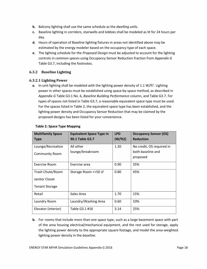
a. In-unit lighting shall be modeled with the lighting power density of 1.1 W/ft2. Lighting
power in other spaces must be established using space-by-space method, as described in
Appendix G Table G3.1 No. 6, Baseline Building Performance column, and Table G3.7. For
types of spaces not listed in Table G3.7, a reasonable equivalent space type must be used.
For the spaces listed in Table 2, the equivalent space type has been established, and the
lighting power density and Occupancy Sensor Reduction that may be claimed by the
proposed designs has been listed for your convenience.
Table 2: Space Type Mapping
Multifamily Space
Type
Equivalent Space Type in
90.1 Table G3.7
LPD
(W/ft2)
Occupancy Sensor (OS)
Reduction
Lounge/Recreation
Community Room
All other
lounge/breakroom
1.20 No credit, OS required in
both baseline and
proposed
Exercise Room Exercise area 0.90 35%
Trash Chute/Room
Janitor Closet
Tenant Storage
Storage Room <>50 sf 0.80 45%
Retail Sales Area 1.70 15%
Laundry Room Laundry/Washing Area 0.60 10%
Elevator (interior) Table G3.1 #16 3.14 25%
b. For rooms that include more than one space type, such as a large basement space with part
of the area housing electrical/mechanical equipment, and the rest used for storage, apply
the lighting power density to the appropriate square footage, and model the area-weighted
lighting power density in the baseline.
ENERGY STAR MFHR Simulation Guidelines Appendix G 2016 Page 19
c. Senior housing projects can use allowances for facilities for the visually impaired in
Appendix G Table G3.7 for spaces used primarily by building residents. For example, 1.15
W/SF lighting power allowance may be used for the corridors in the baseline. To qualify for
the increased allowance, the project must be designed to comply with the light levels in
ANSI/IES RP-28 and must provide housing for seniors and/or people with special visual
needs.
d. Baseline lighting power allowance for corridors must be modeled as 0.83 W/SF instead of
0.5 W/SF listed in Appendix G Table G3.7, to reflect the increase in the illuminance
requirements for corridors since 2004.
e. Decorative lighting allowance described in ASHRAE 90.1 Section 9.6.2 must not be used to
increase the baseline lighting power density for any of the spaces.
6.3.2.2 Lighting Controls
No automatic lighting controls shall be modeled in the baseline except in employee lunch and
break rooms, conference/meeting rooms, and classrooms if applicable, following Appendix G
Table G3.1 No. 6 Baseline Building Performance column. These controls shall be reflected in the
baseline building design lighting schedules, and modeled the same in the baseline and proposed
design. No automatic lighting controls, e.g., controls for daylight utilization and occupancy sensors
in space types not listed above, shall be modeled in the Baseline Building Design.
6.3.3 Proposed Lighting
6.3.3.1 Lighting Power
a. The installed lighting power must be modeled as described in Appendix G Table G3.1 No. 6
(a), and include all power used by the luminaire, including lamps, ballasts/drivers,
transformers, and control devices as described in ASHRAE 90.1 Section 9.1.3, and based on
the actual installed lamp. For example, a screw-based fixture rated at 75 Watt maximum,
with an ENERGY STAR certified 26 Watt CFL installed, may be modeled as 26 Watts, plus any
power consumed by the ballast. For rooms or portions of rooms with no specified
hardwired lighting, in-unit lighting power density of 1.1 W/ft2 shall be modeled.
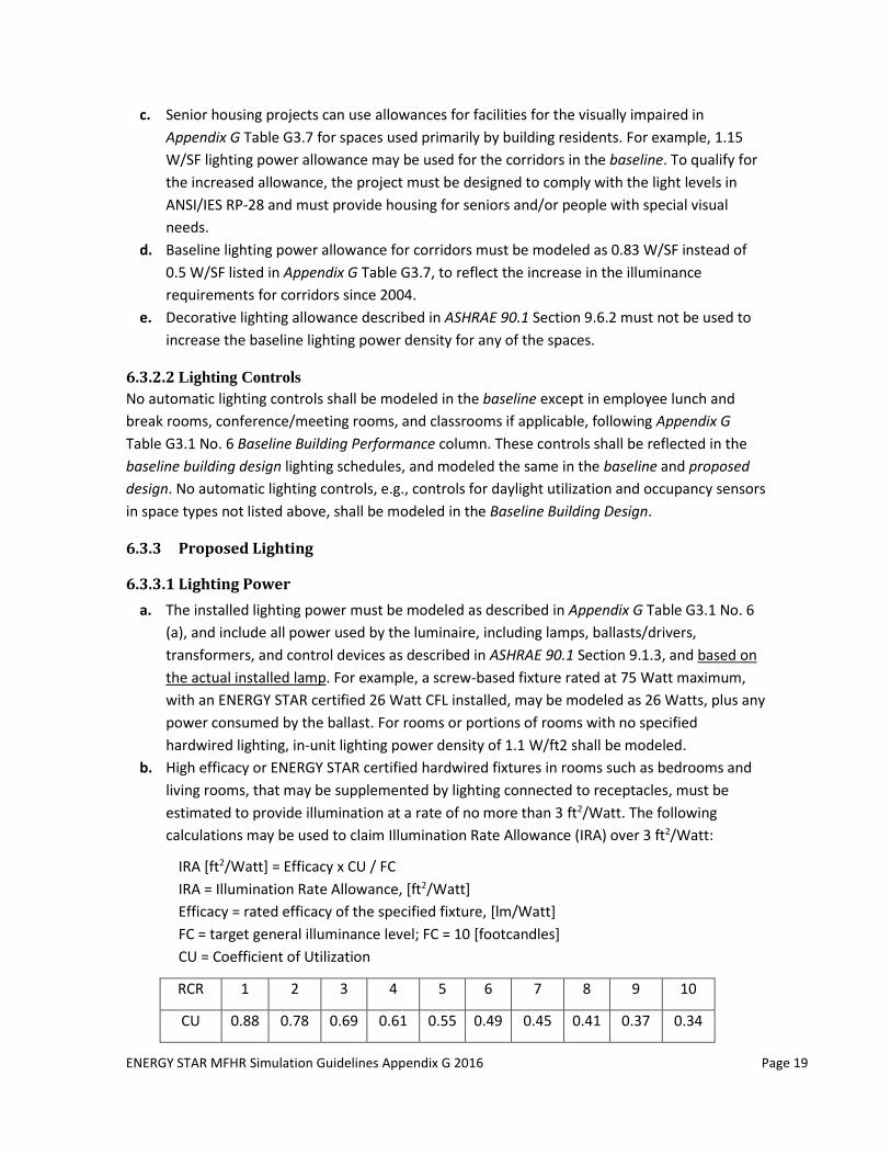
b. High efficacy or ENERGY STAR certified hardwired fixtures in rooms such as bedrooms and
living rooms, that may be supplemented by lighting connected to receptacles, must be
estimated to provide illumination at a rate of no more than 3 ft2/Watt. The following
calculations may be used to claim Illumination Rate Allowance (IRA) over 3 ft2/Watt:
IRA [ft2/Watt] = Efficacy x CU / FC
IRA = Illumination Rate Allowance, [ft2/Watt]
Efficacy = rated efficacy of the specified fixture, [lm/Watt]
FC = target general illuminance level; FC = 10 [footcandles]
CU = Coefficient of Utilization
RCR 1 2 3 4 5 6 7 8 9 10
CU 0.88 0.78 0.69 0.61 0.55 0.49 0.45 0.41 0.37 0.34
ENERGY STAR MFHR Simulation Guidelines Appendix G 2016 Page 20
RCR = Room Cavity Ratio
Rectangular rooms: RCR = 5 x H x (L + W)/(L x W)
Irregularly shaped rooms: RCR = 2.5 x H x P / A
H = vertical distance from the work plane to the center line of the lighting fixture; for
living rooms and bedrooms, the work plane is 4’ above the floor
L = room length, [ft]
W = room width, [ft]
P = room perimeter length, [ft]
A = room area, [ft2]
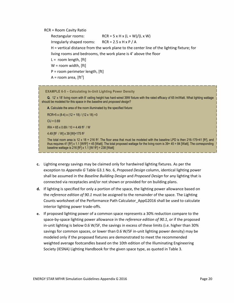
EXAMPLE 6-5 – Calculating In-Unit Lighting Power Density
Q. 12’ x 18’ living room with 8’ ceiling height has hard-wired 39W fixture with the rated efficacy of 65 lm/Watt. What lighting wattage should be modeled for this space in the baseline and proposed design?
A. Calculate the area of the room illuminated by the specified fixture:
RCR=5 x (8-4) x (12 + 18) / (12 x 18) =3
CU = 0.69
IRA = 65 x 0.69 / 10 = 4.49 ft2 / W
4.49 [ft2 / W] x 39 [W]=175 ft2
The total room area is 12 x 18 = 216 ft2. The floor area that must be modeled with the baseline LPD is then 216-175=41 [ft2], and thus requires 41 [ft2] x 1.1 [W/ft2] = 45 [Watt]. The total proposed wattage for the living room is 39+ 45 = 84 [Watt]. The corresponding baseline wattage is 216 [ft2] x 1.1 [W/ ft2] = 238 [Watt]
c. Lighting energy savings may be claimed only for hardwired lighting fixtures. As per the
exception to Appendix G Table G3.1 No. 6, Proposed Design column, identical lighting power
shall be assumed in the Baseline Building Design and Proposed Design for any lighting that is
connected via receptacles and/or not shown or provided for on building plans.
d. If lighting is specified for only a portion of the space, the lighting power allowance based on
the reference edition of 90.1 must be assigned to the remainder of the space. The Lighting
Counts worksheet of the Performance Path Calculator_AppG2016 shall be used to calculate
interior lighting power trade-offs.
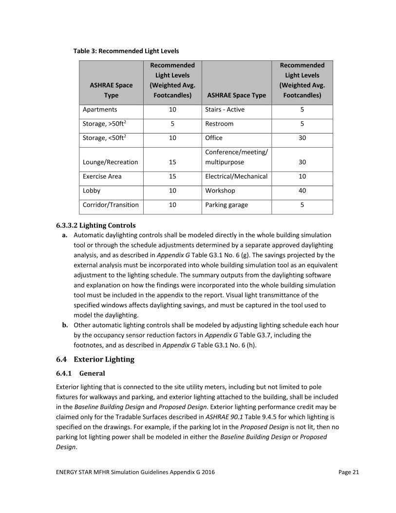
e. If proposed lighting power of a common space represents a 30% reduction compare to the
space-by-space lighting power allowance in the reference edition of 90.1, or if the proposed
in-unit lighting is below 0.6 W/SF, the savings in excess of these limits (i.e. higher than 30%
savings for common spaces, or lower than 0.6 W/SF in-unit lighting power density) may be
modeled only if the proposed fixtures are demonstrated to meet the recommended
weighted average footcandles based on the 10th edition of the Illuminating Engineering
Society (IESNA) Lighting Handbook for the given space type, as quoted in Table 3.
ENERGY STAR MFHR Simulation Guidelines Appendix G 2016 Page 21
Table 3: Recommended Light Levels
ASHRAE Space
Type
Recommended
Light Levels
(Weighted Avg.
Footcandles) ASHRAE Space Type
Recommended
Light Levels
(Weighted Avg.
Footcandles)
Apartments 10 Stairs - Active 5
Storage, >50ft2 5 Restroom 5
Storage, <50ft2 10 Office 30
Lounge/Recreation 15
Conference/meeting/
multipurpose 30
Exercise Area 15 Electrical/Mechanical 10
Lobby 10 Workshop 40
Corridor/Transition 10 Parking garage 5
6.3.3.2 Lighting Controls
a. Automatic daylighting controls shall be modeled directly in the whole building simulation
tool or through the schedule adjustments determined by a separate approved daylighting
analysis, and as described in Appendix G Table G3.1 No. 6 (g). The savings projected by the
external analysis must be incorporated into whole building simulation tool as an equivalent
adjustment to the lighting schedule. The summary outputs from the daylighting software
and explanation on how the findings were incorporated into the whole building simulation
tool must be included in the appendix to the report. Visual light transmittance of the
specified windows affects daylighting savings, and must be captured in the tool used to
model the daylighting.
b. Other automatic lighting controls shall be modeled by adjusting lighting schedule each hour
by the occupancy sensor reduction factors in Appendix G Table G3.7, including the
footnotes, and as described in Appendix G Table G3.1 No. 6 (h).
6.4 Exterior Lighting
6.4.1 General
Exterior lighting that is connected to the site utility meters, including but not limited to pole
fixtures for walkways and parking, and exterior lighting attached to the building, shall be included
in the Baseline Building Design and Proposed Design. Exterior lighting performance credit may be
claimed only for the Tradable Surfaces described in ASHRAE 90.1 Table 9.4.5 for which lighting is
specified on the drawings. For example, if the parking lot in the Proposed Design is not lit, then no
parking lot lighting power shall be modeled in either the Baseline Building Design or Proposed
Design.
ENERGY STAR MFHR Simulation Guidelines Appendix G 2016 Page 22
Performance credit can only be modeled if associated with energy-efficiency, rather than a
decrease in illumination, or reduction in the illuminated area or surface.
Lighting specified for apartment balconies can be evaluated as Tradable, using “Other doors”, or
as Non-tradable, using “Building façades”.
Exterior lighting for unregulated applications such as swimming pools, athletic fields, etc. must be
modeled as energy neutral.
Use the General Lighting worksheet of the Performance Path Calculator_AppG2016 for exterior
lighting calculations.
6.4.2 Schedule
Exterior lighting shall be modeled as lit for no more than 12 hours per day. The same schedules
must be modeled in the baseline and proposed design, and is assumed to include the specified
lighting controls.
6.4.3 Lighting Power
6.4.3.1 Baseline Lighting Power
a. Exterior lighting in areas identified as “Tradable Surfaces” in Appendix G Table G3.6 shall be
modeled with the baseline lighting power shown in Table G3.6. Tradable exterior lighting
applications include uncovered parking areas, building grounds, building entrances and
exits, canopies and overhangs, and outdoor sales areas. The baseline exterior lighting is the
product of the lighting allowance from Appendix G Table G3.6 and the associated area or
length for which illumination is provided in the proposed design.
Other exterior lighting, including unregulated and non-tradable applications, shall be
modeled the same in the baseline building design as in the proposed design.
6.4.3.2 Proposed Lighting Power
a. The lighting power in the Proposed Design must be modeled as described in Appendix G
Table G3.1 No. 6 (a), and include all power used by the luminaire, including lamps,
ballasts/drivers, transformers, and control devices as described in ASHRAE 90.1 Section
9.1.3, and based on the actual installed lamp.
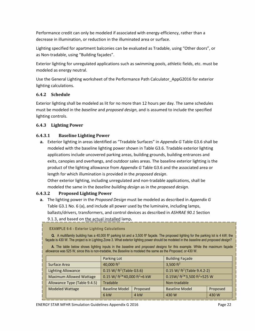
EXAMPLE 6-6 - Exterior Lighting Calculations
Q. A multifamily building has a 40,000 ft² parking lot and a 3,500 ft² façade. The proposed lighting for the parking lot is 4 kW; the façade is 430 W. The project is in Lighting Zone 3. What exterior lighting power should be modeled in the baseline and proposed design?
A. The table below shows lighting inputs in the baseline and proposed designs for this example. While the maximum façade allowance was 525 W, since this is non-tradable, the Baseline is modeled the same as the Proposed, or 430 W.
Parking Lot Building Façade
Surface Area 40,000 ft2 3,500 ft2
Lighting Allowance 0.15 W/ ft2 (Table G3.6) 0.15 W/ ft2 (Table 9.4.2-2)
Maximum Allowed Wattage 0.15 W/ ft2*40,000 ft2=6 kW 0.15W/ ft2*3,500 ft2=525 W
Allowance Type (Table 9.4.5) Tradable Non-tradable
Modeled Wattage Baseline Model Proposed Baseline Model Proposed
6 kW 4 kW 430 W 430 W
ENERGY STAR MFHR Simulation Guidelines Appendix G 2016 Page 23
6.5 Heating, Ventilation, and Air Conditioning
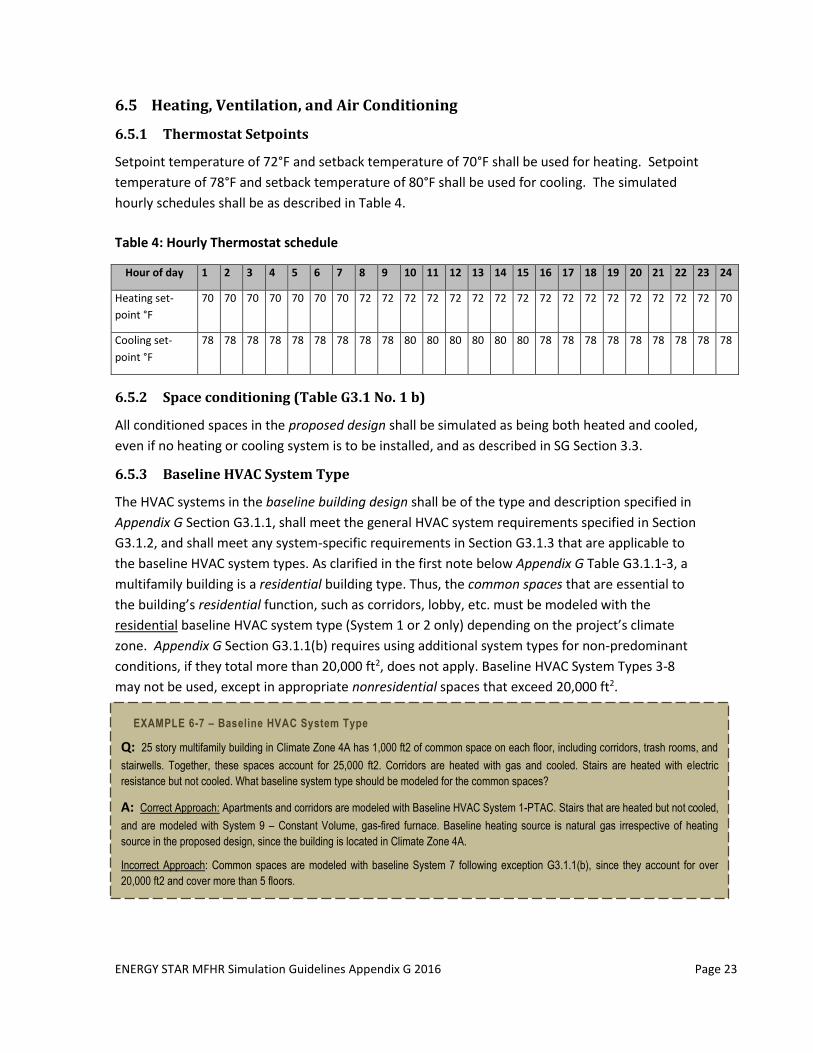
6.5.1 Thermostat Setpoints
Setpoint temperature of 72°F and setback temperature of 70°F shall be used for heating. Setpoint
temperature of 78°F and setback temperature of 80°F shall be used for cooling. The simulated
hourly schedules shall be as described in Table 4.
Table 4: Hourly Thermostat schedule
6.5.2 Space conditioning (Table G3.1 No. 1 b)
All conditioned spaces in the proposed design shall be simulated as being both heated and cooled,
even if no heating or cooling system is to be installed, and as described in SG Section 3.3.
6.5.3 Baseline HVAC System Type
The HVAC systems in the baseline building design shall be of the type and description specified in
Appendix G Section G3.1.1, shall meet the general HVAC system requirements specified in Section
G3.1.2, and shall meet any system-specific requirements in Section G3.1.3 that are applicable to
the baseline HVAC system types. As clarified in the first note below Appendix G Table G3.1.1-3, a
multifamily building is a residential building type. Thus, the common spaces that are essential to
the building’s residential function, such as corridors, lobby, etc. must be modeled with the
residential baseline HVAC system type (System 1 or 2 only) depending on the project’s climate
zone. Appendix G Section G3.1.1(b) requires using additional system types for non-predominant
conditions, if they total more than 20,000 ft2, does not apply. Baseline HVAC System Types 3-8
may not be used, except in appropriate nonresidential spaces that exceed 20,000 ft2.
Hour of day 1 2 3 4 5 6 7 8 9 10 11 12 13 14 15 16 17 18 19 20 21 22 23 24
Heating set-
point °F
70 70 70 70 70 70 70 72 72 72 72 72 72 72 72 72 72 72 72 72 72 72 72 70
Cooling set-
point °F
78 78 78 78 78 78 78 78 78 80 80 80 80 80 80 78 78 78 78 78 78 78 78 78
EXAMPLE 6-7 – Baseline HVAC System Type
Q: 25 story multifamily building in Climate Zone 4A has 1,000 ft2 of common space on each floor, including corridors, trash rooms, and
stairwells. Together, these spaces account for 25,000 ft2. Corridors are heated with gas and cooled. Stairs are heated with electric
resistance but not cooled. What baseline system type should be modeled for the common spaces?
A: Correct Approach: Apartments and corridors are modeled with Baseline HVAC System 1-PTAC. Stairs that are heated but not cooled,
and are modeled with System 9 – Constant Volume, gas-fired furnace. Baseline heating source is natural gas irrespective of heating
source in the proposed design, since the building is located in Climate Zone 4A.
Incorrect Approach: Common spaces are modeled with baseline System 7 following exception G3.1.1(b), since they account for over
20,000 ft2 and cover more than 5 floors.
ENERGY STAR MFHR Simulation Guidelines Appendix G 2016 Page 24
6.5.4 Baseline HVAC System Capacity
Baseline HVAC system coil capacities shall be oversized by 15% for cooling and 25% for heating;
i.e., the ratio between the capacities used in the annual simulations and the capacities
determined by the sizing runs shall be 1.15 for cooling and 1.25 for heating. Only the coil
capacities, and not the fan flow rates, shall be over-sized.
Weather conditions used in sizing runs to determine baseline equipment capacities shall be based
either on hourly historical weather files containing typical peak conditions or on design days
developed using 99.6% heating design temperatures and 1% dry-bulb and 1% wet-bulb cooling
design temperatures per Appendix G Section G3.1.2.2.1. The typical hourly schedules for lighting,
equipment, occupancy, and infiltration must be used in the sizing runs for Systems 1 and 2, and
not the peak loads.
Where multiple HVAC zones or residential spaces are combined into a single thermal block, the
efficiencies for baseline HVAC Systems shall be based on the equipment capacity of the thermal
block divided by the number of HVAC zones or residential spaces.
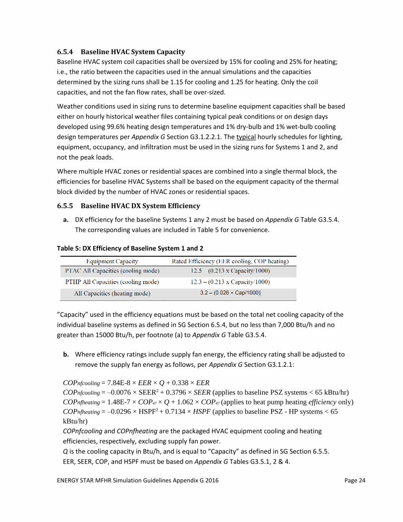
6.5.5 Baseline HVAC DX System Efficiency
a. DX efficiency for the baseline Systems 1 any 2 must be based on Appendix G Table G3.5.4.
The corresponding values are included in Table 5 for convenience.
Table 5: DX Efficiency of Baseline System 1 and 2
”Capacity” used in the efficiency equations must be based on the total net cooling capacity of the
individual baseline systems as defined in SG Section 6.5.4, but no less than 7,000 Btu/h and no
greater than 15000 Btu/h, per footnote (a) to Appendix G Table G3.5.4.
b. Where efficiency ratings include supply fan energy, the efficiency rating shall be adjusted to
remove the supply fan energy as follows, per Appendix G Section G3.1.2.1:
COPnfcooling = 7.84E-8 × EER × Q + 0.338 × EER
COPnfcooling = –0.0076 × SEER2 + 0.3796 × SEER (applies to baseline PSZ systems < 65 kBtu/hr)
COPnfheating = 1.48E-7 × COP47 × Q + 1.062 × COP47 (applies to heat pump heating efficiency only)
COPnfheating = –0.0296 × HSPF2 + 0.7134 × HSPF (applies to baseline PSZ - HP systems < 65
kBtu/hr)
COPnfcooling and COPnfheating are the packaged HVAC equipment cooling and heating
efficiencies, respectively, excluding supply fan power.
Q is the cooling capacity in Btu/h, and is equal to “Capacity” as defined in SG Section 6.5.5.
EER, SEER, COP, and HSPF must be based on Appendix G Tables G3.5.1, 2 & 4.
ENERGY STAR MFHR Simulation Guidelines Appendix G 2016 Page 25
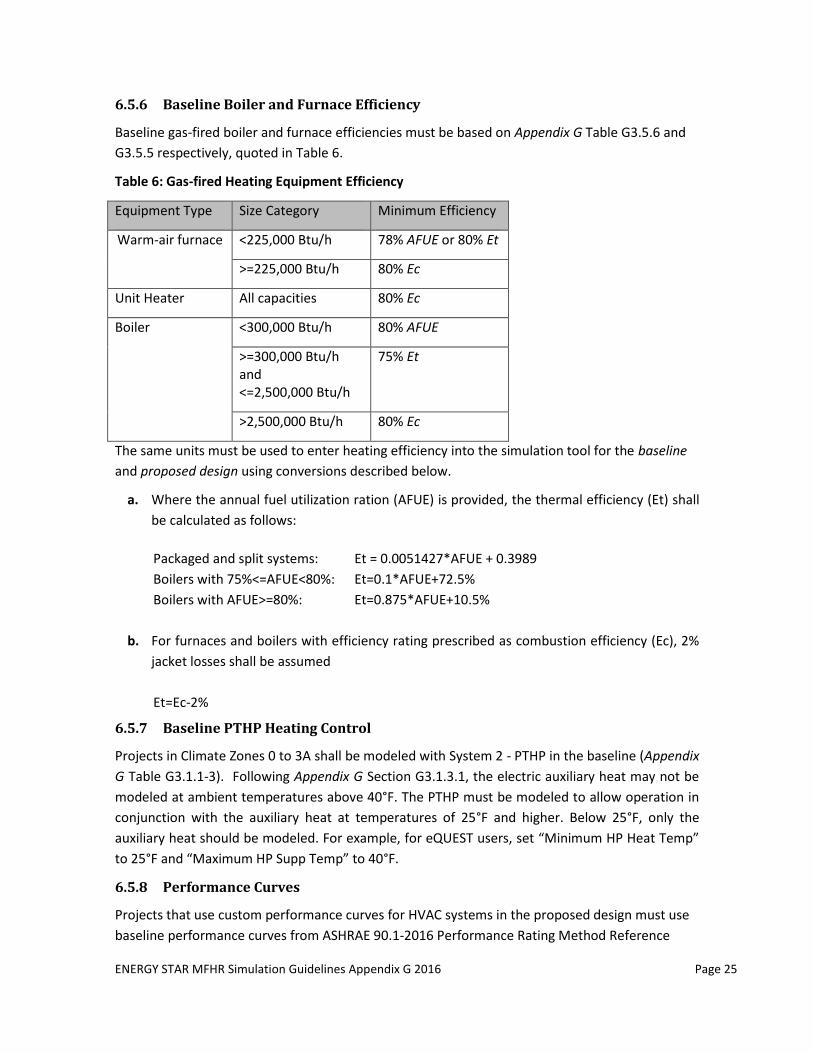
6.5.6 Baseline Boiler and Furnace Efficiency
Baseline gas-fired boiler and furnace efficiencies must be based on Appendix G Table G3.5.6 and
G3.5.5 respectively, quoted in Table 6.
Table 6: Gas-fired Heating Equipment Efficiency
Equipment Type Size Category Minimum Efficiency
Warm-air furnace <225,000 Btu/h 78% AFUE or 80% Et
>=225,000 Btu/h 80% Ec
Unit Heater All capacities 80% Ec
Boiler <300,000 Btu/h 80% AFUE
>=300,000 Btu/h and <=2,500,000 Btu/h
75% Et
>2,500,000 Btu/h 80% Ec
The same units must be used to enter heating efficiency into the simulation tool for the baseline
and proposed design using conversions described below.
a. Where the annual fuel utilization ration (AFUE) is provided, the thermal efficiency (Et) shall
be calculated as follows:
Packaged and split systems: Et = 0.0051427*AFUE + 0.3989
Boilers with 75%<=AFUE<80%: Et=0.1*AFUE+72.5%
Boilers with AFUE>=80%: Et=0.875*AFUE+10.5%
b. For furnaces and boilers with efficiency rating prescribed as combustion efficiency (Ec), 2%
jacket losses shall be assumed
Et=Ec-2%
6.5.7 Baseline PTHP Heating Control
Projects in Climate Zones 0 to 3A shall be modeled with System 2 - PTHP in the baseline (Appendix
G Table G3.1.1-3). Following Appendix G Section G3.1.3.1, the electric auxiliary heat may not be
modeled at ambient temperatures above 40°F. The PTHP must be modeled to allow operation in
conjunction with the auxiliary heat at temperatures of 25°F and higher. Below 25°F, only the
auxiliary heat should be modeled. For example, for eQUEST users, set “Minimum HP Heat Temp”
to 25°F and “Maximum HP Supp Temp” to 40°F.
6.5.8 Performance Curves
Projects that use custom performance curves for HVAC systems in the proposed design must use
baseline performance curves from ASHRAE 90.1-2016 Performance Rating Method Reference
ENERGY STAR MFHR Simulation Guidelines Appendix G 2016 Page 26
Manual 2 which are better aligned with 90.1 efficiency requirements than some default software
curves.
6.5.9 Proposed HVAC System Capacity and Efficiency
The Proposed Design equipment shall be modeled using the specified system type, capacity, and
supply airflow. Auto-sizing cannot be used.
In all cases, the same modeling method and/or efficiency units shall be used in the Baseline and
Proposed model. Conversions provided in Section 6.5.1 must be used.
Where efficiency ratings include supply fan energy, the efficiency rating shall be adjusted to
remove the supply fan energy from the efficiency rating in the baseline building design using
manufacturers’ data at the AHRI rated conditions, and equations below.
Exception: If the supply fan in the proposed design cycles with load and fan energy is included in
the energy-efficiency rating of the equipment, fan energy shall not be modeled explicitly.
Where efficiency rating of the specified DX cooling and heating systems includes supply fan
energy, the efficiency rating shall be adjusted to remove the supply fan energy as follows:
a. Cooling:
EER=Net Cooling [Btu/h] / Total Input Power [W] Indoor Fan Power [W]= (Gross Cooling [Btu/h]-Net Cooling [Btu/h])/3.412[Btu/h x W] COPnfcooling =Gross Cooling [Btu/h]/((Total Input Power [W]–Indoor Fan Power[W])x3.412[Btu/h x W])
b. Heating:
COPheating=Net Heating [Btu/h]/ (Total Input Power [W] x 3.412 [Btu/h x W] Indoor Fan Power [W]= (Net Heating [Btu/h]-Gross Heating [Btu/h])/3.412[Btu/h x W] COPnfheating =Gross Heating [Btu/h]/((Total Input Power [W] – Indoor Fan Power [W])x3.412[Btu/h x W])
2 http://www.pnnl.gov/main/publications/external/technical_reports/PNNL-25130.pdf,
ENERGY STAR MFHR Simulation Guidelines Appendix G 2016 Page 27
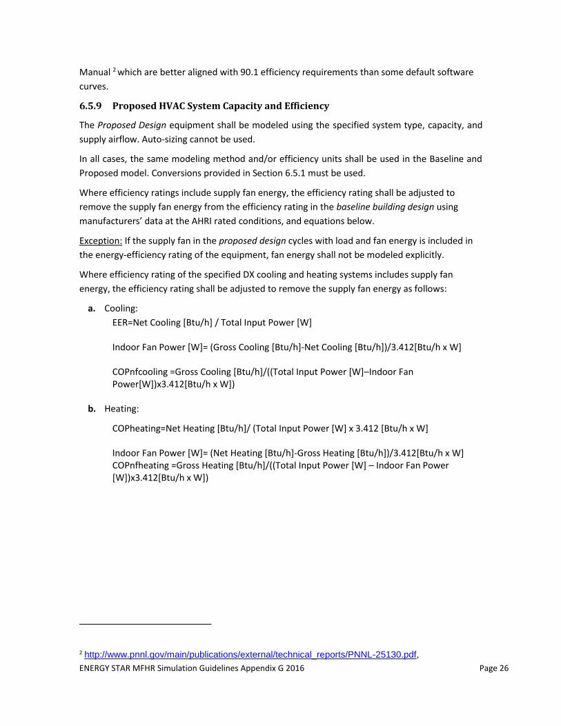
EXAMPLE 6-8 – Proposed HVAC System Efficiency
Q: Apartments in the proposed design have EER 13 through-the-wall air-conditioners that cycle with the cooling load, and hydronic
baseboards. Ventilation is provided by an energy recovery ventilator. Corridors are served by the rooftop unit (RTU) with parameters
specified below. How should cooling efficiency of the RTU and through-the-wall AC be calculated and modeled in eQUEST?
A: RTU cooling efficiency with fan power extracted (COPnfcooling) is calculated as shown below. EIR=0.2214 is entered in eQUEST. Fan
energy is modeled based on the BHP of the specified RTU supply fan.
Through-the-wall AC cycles with load, thus fan power does not have to be extracted and explicitly modeled. The cooling efficiency
including fan power is calculated as COP=13/3.412=3.81. It is entered in eQUEST as EIR=1/3.81=0.262. AC fan power is modeled as 0
W/CFM, since it is captured in the efficiency rating.
6.5.10 HVAC Fan System Energy
6.5.10.1 Baseline System Power
a. The design supply flow rate for the baseline systems, except System 8 and 9, must be based
on a supply-air-to-room temperature set-point difference of 20°F or the minimum outdoor
airflow rate, whichever is greater (Appendix G Section G3.1.2.8). For baseline Systems 9 and
10, the temperature difference between the supply air temperature setpoint of 105°F and
the design space heating temperature setpoint shall be used instead of 20°F difference
(Appendix G Section G3.1.2.9)
The baseline system fan power must be modeled following Appendix G Section G3.1.2.9.
The fan power allowance for Baseline Systems 1, 2, 9, and 10, which are common in
multifamily projects, is shown below for convenience.
Pfan = CFMS ⋅ 0.3
Pfan = electric power to fan motor (watts)
CFMS = the baseline system maximum design supply fan airflow rate in cfm, established as
described above.
ENERGY STAR MFHR Simulation Guidelines Appendix G 2016 Page 28
Fan power allowance for baseline Systems 9 and 10 may be increased to account for non-
mechanical cooling, if provided in the proposed design, as described in G3.1.2.9.
b. The calculated system fan power shall be distributed to supply, return, exhaust, and relief
fans in the same proportion as the proposed design. It represents the total fan power
allowance including supply, return, and exhaust fans, central and zonal. No additional fan
energy allowance, such as for continuously or intermittently running local exhaust fans
serving dwelling units or dedicated make-up air unit that may be specified for the proposed
design, shall be included in the baseline.
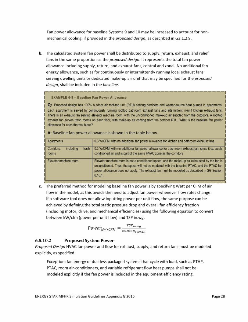
EXAMPLE 6-9 – Baseline Fan Power Allowance
Q: Proposed design has 100% outdoor air roof-top unit (RTU) serving corridors and waster-source heat pumps in apartments.
Each apartment is served by continuously running rooftop bathroom exhaust fans and intermittent in-unit kitchen exhaust fans.
There is an exhaust fan serving elevator machine room, with the unconditioned make-up air suppled from the outdoors. A rooftop
exhaust fan serves trash rooms on each floor, with make-up air coming from the corridor RTU. What is the baseline fan power
allowance for each thermal block?
A: Baseline fan power allowance is shown in the table below.
Apartments 0.3 W/CFM, with no additional fan power allowance for kitchen and bathroom exhaust fans
Corridors, including trash
rooms
0.3 W/CFM, with no additional fan power allowance for trash room exhaust fan, since it exhausts
conditioned air and is part of the same HVAC zone as the corridors
Elevator machine room Elevator machine room is not a conditioned space, and the make-up air exhausted by the fan is
unconditioned. Thus, the space will not be modeled with the baseline PTAC, and the PTAC fan
power allowance does not apply. The exhaust fan must be modeled as described in SG Section
6.10.1.
c. The preferred method for modeling baseline fan power is by specifying Watt per CFM of air
flow in the model, as this avoids the need to adjust fan power whenever flow rates change.
If a software tool does not allow inputting power per unit flow, the same purpose can be
achieved by defining the total static pressure drop and overall fan efficiency fraction
(including motor, drive, and mechanical efficiencies) using the following equation to convert
between kW/cfm (power per unit flow) and TSP in.wg.
𝑃𝑜𝑤𝑒𝑟𝑘𝑊/𝐶𝐹𝑀 =𝑇𝑆𝑃𝑖𝑛.𝑤𝑔
8520×𝜂𝑜𝑣𝑒𝑟𝑎𝑙𝑙
6.5.10.2 Proposed System Power
Proposed Design HVAC fan power and flow for exhaust, supply, and return fans must be modeled
explicitly, as specified.
Exception: fan energy of ductless packaged systems that cycle with load, such as PTHP,
PTAC, room air-conditioners, and variable refrigerant flow heat pumps shall not be
modeled explicitly if the fan power is included in the equipment efficiency rating.
ENERGY STAR MFHR Simulation Guidelines Appendix G 2016 Page 29
6.5.10.3 HVAC Fan System Schedule
Baseline Building Design: Supply and return fans shall operate continuously whenever spaces are
occupied and shall be cycled to meet heating and cooling loads during unoccupied hours
(Appendix G Section G3.1.2.4). Following this rule, the baseline HVAC systems in apartments and
corridors must be modeled as running continuously. Unoccupied periods may exist in supporting
spaces such as rental office, mechanical rooms, etc.
Proposed Design: HVAC fans that provide outdoor air for ventilation shall run continuously
whenever spaces are occupied, and shall be cycled to meet heating and cooling loads during
unoccupied hours. (Appendix G Table G3.1 No. 4).
6.5.11 HVAC Distribution System
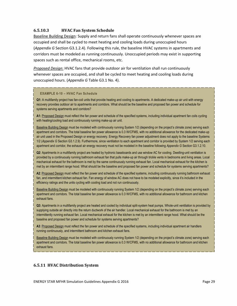
EXAMPLE 6-10 – HVAC Fan Schedule
Q1: A multifamily project has fan-coil units that provide heating and cooling to apartments. A dedicated make-up air unit with energy
recovery provides outdoor air to apartments and corridors. What should be the baseline and proposed fan power and schedule for
systems serving apartments and corridors?
A1: Proposed Design must reflect the fan power and schedule of the specified systems, including individual apartment fan coils cycling
with heating/cooling load and continuously running make-up air unit.
Baseline Building Design must be modeled with continuously running System 1/2 (depending on the project’s climate zone) serving each
apartment and corridors. The total baseline fan power allowance is 0.3 W/CFMS, with no additional allowance for the dedicated make-up
air unit used in the Proposed Design or energy recovery. Energy Recovery fan power adjustment does not apply to the baseline Systems
1/2 (Appendix G Section G3.1.2.9). Furthermore, since ventilation to each apartment and corridor is provided by System 1/2 serving each
apartment and corridor, the exhaust air energy recovery must not be modeled in the baseline following Appendix G Section G3.1.2.10.
Q2: Apartments in a multifamily project are heated by hydronic baseboards and use window AC for cooling. Dwelling-unit ventilation is
provided by a continuously running bathroom exhaust fan that pulls make-up air through trickle vents in bedrooms and living areas. Local
mechanical exhaust for the bathroom is met by the same continuously running exhaust fan. Local mechanical exhaust for the kitchen is
met by an intermittent range hood. What should be the baseline and proposed fan power and schedule for systems serving apartments?
A2: Proposed Design must reflect the fan power and schedule of the specified systems, including continuously running bathroom exhaust
fan, and intermittent kitchen exhaust fan. Fan energy of window AC does not have to be modeled explicitly, since it’s included in the
efficiency ratings and the units cycling with cooling load and not run continuously.
Baseline Building Design must be modeled with continuously running System 1/2 (depending on the project’s climate zone) serving each
apartment and corridors. The total baseline fan power allowance is 0.3 W/CFMS, with no additional allowance for bathroom and kitchen
exhaust fans.
Q3: Apartments in a multifamily project are heated and cooled by individual split-system heat pumps. Whole-unit ventilation is provided by
supplying outside air directly into the return ductwork of the air handler. Local mechanical exhaust for the bathroom is met by an
intermittently running exhaust fan. Local mechanical exhaust for the kitchen is met by an intermittent range hood. What should be the
baseline and proposed fan power and schedule for systems serving apartments?
A3: Proposed Design must reflect the fan power and schedule of the specified systems, including individual apartment air handlers
running continuously, and intermittent bathroom and kitchen exhaust fans.
Baseline Building Design must be modeled with continuously running System 1/2 (depending on the project’s climate zone) serving each
apartment and corridors. The total baseline fan power allowance is 0.3 W/CFMS, with no additional allowance for bathroom and kitchen
exhaust fans.
ENERGY STAR MFHR Simulation Guidelines Appendix G 2016 Page 30
6.5.11.1 Baseline Hot Water Distribution System
Hot water pump energy, and hot water loop control on projects with the baseline system 1 –
PTAC shall be modeled as described in Appendix G sections G3.1.3.3, G3.1.3.4 and G3.1.3.5, and
as described below:
a. Hot-water design supply temperature shall be modeled as 180°F and design return
temperature as 130°F.
b. Hot-water supply temperature shall be reset based on outdoor dry-bulb temperature using
the following schedule: 180°F at 20°F and below, 150°F at 50°F and above, and ramped
linearly between 180°F and 150°F at temperatures between 20°F and 50°F.
c. Hot-water pump power shall be modeled as 19W/GPM.
d. Pumping system shall be modeled with continuous variable flow, i.e. with two way valves
on PTACs. The minimum flow through the boiler shall be 25% of design flow rate.
e. Systems serving 120,000 ft2 or more shall be modeled with variable-speed drives, and
systems serving less than 120,000 ft2 shall be modeled as riding the pump curve. PTACs
must be modeled with the two-way valves on the hot water loop.
f. Hot water loop should be modeled as operating “on demand”, with pumps shut off when
heating is not required.
6.5.11.2 Proposed Hot Water Distribution
HVAC pumps in the Proposed Design shall be modeled using the actual system parameters
including but not limited to head, flow control, and pump motor efficiency.
6.5.11.3 Piping and Duct Losses
Do not model piping or duct losses. Refer to program prerequisites for specifications relating to
pipe insulation, duct insulation and duct leakage amounts.
Projects may pursue performance credit for sealing central exhaust ventilation ductwork. To
receive this credit, the actual duct leakage measured during the inspection phase of the project as
part of the Testing and Verification Protocols conducted on the building, must be below the
program prerequisite. To model the energy savings, the actual measured leakage shall be added
to exhaust CFM in the Proposed Design. The exhaust leakage in the Baseline Building Design shall
be modeled by adding the leakage allowed by the prerequisites to the specified exhaust CFM.
6.5.12 Mechanical Ventilation
6.5.12.1 Baseline Building Design
a. Ventilation in Dwelling Units
Minimum ventilation outdoor air intake flow shall be the same as in the proposed design
(Appendix G, Section G3.1.2.5), except where indicated otherwise in the following provisions.
The baseline ventilation method (mechanical versus natural) and controls (continuous versus
intermittent) must be modeled as specified for each application.
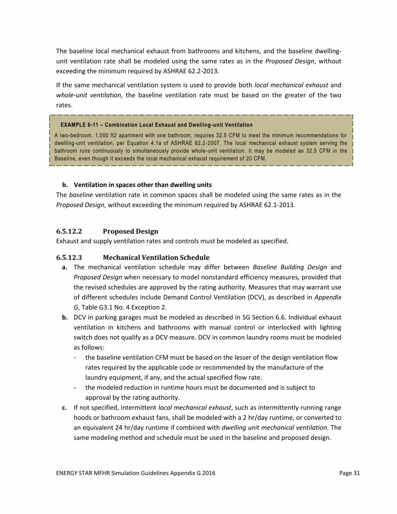
ENERGY STAR MFHR Simulation Guidelines Appendix G 2016 Page 31
The baseline local mechanical exhaust from bathrooms and kitchens, and the baseline dwelling-
unit ventilation rate shall be modeled using the same rates as in the Proposed Design, without
exceeding the minimum required by ASHRAE 62.2-2013.
If the same mechanical ventilation system is used to provide both local mechanical exhaust and
whole-unit ventilation, the baseline ventilation rate must be based on the greater of the two
rates.
EXAMPLE 6-11 – Combination Local Exhaust and Dwelling -unit Ventilation
A two-bedroom, 1,000 ft2 apartment with one bathroom, requires 32.5 CFM to meet the minimum recommendations for
dwelling-unit ventilation, per Equation 4.1a of ASHRAE 62.2 -2007. The local mechanical exhaust system serving the
bathroom runs continuously to simultaneously provide whole -unit ventilation. It may be modeled as 32.5 CFM in the
Baseline, even though it exceeds the local mechanical exhaust requirement of 20 CFM.
b. Ventilation in spaces other than dwelling units
The baseline ventilation rate in common spaces shall be modeled using the same rates as in the
Proposed Design, without exceeding the minimum required by ASHRAE 62.1-2013.
6.5.12.2 Proposed Design
Exhaust and supply ventilation rates and controls must be modeled as specified.
6.5.12.3 Mechanical Ventilation Schedule
a. The mechanical ventilation schedule may differ between Baseline Building Design and
Proposed Design when necessary to model nonstandard efficiency measures, provided that
the revised schedules are approved by the rating authority. Measures that may warrant use
of different schedules include Demand Control Ventilation (DCV), as described in Appendix
G, Table G3.1 No. 4 Exception 2.
b. DCV in parking garages must be modeled as described in SG Section 6.6. Individual exhaust
ventilation in kitchens and bathrooms with manual control or interlocked with lighting
switch does not qualify as a DCV measure. DCV in common laundry rooms must be modeled
as follows:
- the baseline ventilation CFM must be based on the lesser of the design ventilation flow
rates required by the applicable code or recommended by the manufacture of the
laundry equipment, if any, and the actual specified flow rate.
- the modeled reduction in runtime hours must be documented and is subject to
approval by the rating authority.
c. If not specified, intermittent local mechanical exhaust, such as intermittently running range
hoods or bathroom exhaust fans, shall be modeled with a 2 hr/day runtime, or converted to
an equivalent 24 hr/day runtime if combined with dwelling unit mechanical ventilation. The
same modeling method and schedule must be used in the baseline and proposed design.
ENERGY STAR MFHR Simulation Guidelines Appendix G 2016 Page 32
6.5.13 District Systems
The baseline HVAC system must be modeled as described in Appendix G, Section G3.1.1.1 – 5,
G3.1.3.9, and G3.1.3.10 for projects with purchased chilled water and heat. The purchased chilled
water energy use must be converted into the associated energy use using IPLV from Appendix G
Table G3.5.3, based on the modeled cooling load, and type and number of chillers prescribed by
G3.1.3.7. The purchased heat must be converted into the associated energy use using boiler
efficiency from Table IPLV from Appendix G Table G3.5.6, based on the modeled heating load, and
type and number of boilers prescribed by G3.1.3.2.
The proposed HVAC system must be modeled as specified, with the purchased chilled water
and/or heat, and including the associated pumps and other related equipment. Purchased chilled
water and heat must be converted to source energy assuming the same type and number of
chillers and boilers as in the baseline, the minimum part load IPLV chiller, and the minimum boiler
efficiency from Section 6 of the reference edition of 90.1.
6.6 Other Heating and Ventilation Systems
6.6.1 Systems for snow/Ice melt, pipe freeze protection, and garage heating
If systems for snow/ice melting, freeze protection for piping, and/or other space heating systems
are installed in a garage or other unconditioned areas (such as carports, passageways, sidewalks),
the associated energy use must be included in the Proposed Design and As-Built, but not the
Baseline.
6.6.2 Ventilation Control in Garages
Baseline and proposed garage exhaust fans must be modeled as described below, and treated as
a regulated load.
E base = BHP base x 0.746 / Eff base x 8760 [hrs/yr]
E prop = BHP prop x 0.746 / Eff prop x 365 x (8.4 + PDW min x 15.6)
where,
E base [kWh] = annual energy consumption of the baseline garage exhaust fan
BHP prop = brake horse power of the specified exhaust fan
BHP base = brake horse power of the baseline exhaust fan; BHP base = BHP x CFMbase /CFMprop
CFM prop = specified design exhaust CFM
CFM base = the lesser of the CFM prop and A[ft2] x 0.75 [CFM/ft2], where A is the garage floor
area and 0.75 [CFM/ft2] is the garage exhaust flow required by ASHRAE Standard 62.1
Eff base = baseline motor efficiency from Appendix G Table G3.9.1 for the next motor size
larger than BHP
E prop [kWh] = annual energy consumption of the proposed garage exhaust fan
Eff prop = electrical efficiency of the specified fan motor
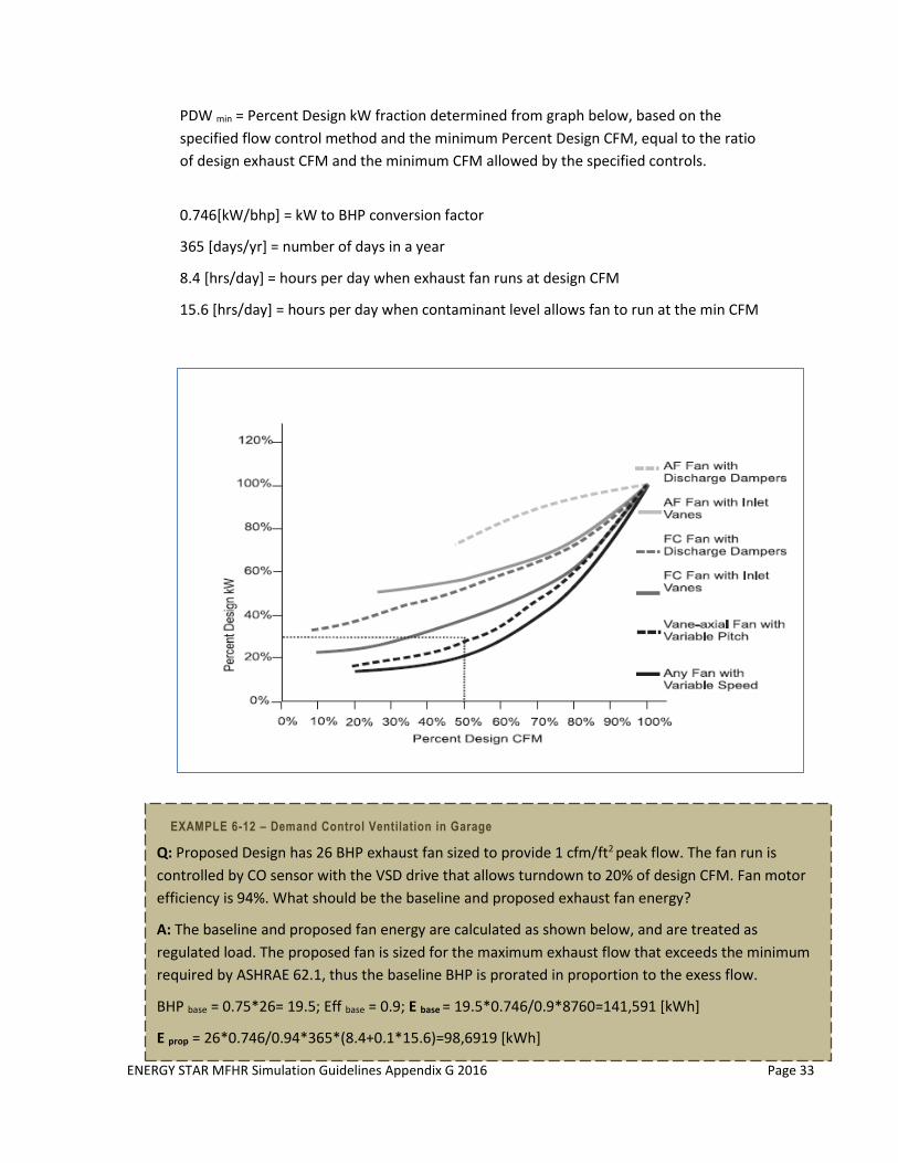
ENERGY STAR MFHR Simulation Guidelines Appendix G 2016 Page 33
PDW min = Percent Design kW fraction determined from graph below, based on the
specified flow control method and the minimum Percent Design CFM, equal to the ratio
of design exhaust CFM and the minimum CFM allowed by the specified controls.
0.746[kW/bhp] = kW to BHP conversion factor
365 [days/yr] = number of days in a year
8.4 [hrs/day] = hours per day when exhaust fan runs at design CFM
15.6 [hrs/day] = hours per day when contaminant level allows fan to run at the min CFM
EXAMPLE 6-12 – Demand Control Ventilation in Garage
Q: Proposed Design has 26 BHP exhaust fan sized to provide 1 cfm/ft2 peak flow. The fan run is
controlled by CO sensor with the VSD drive that allows turndown to 20% of design CFM. Fan motor
efficiency is 94%. What should be the baseline and proposed exhaust fan energy?
A: The baseline and proposed fan energy are calculated as shown below, and are treated as
regulated load. The proposed fan is sized for the maximum exhaust flow that exceeds the minimum
required by ASHRAE 62.1, thus the baseline BHP is prorated in proportion to the exess flow.
BHP base = 0.75*26= 19.5; Eff base = 0.9; E base = 19.5*0.746/0.9*8760=141,591 [kWh]
E prop = 26*0.746/0.94*365*(8.4+0.1*15.6)=98,6919 [kWh]
ENERGY STAR MFHR Simulation Guidelines Appendix G 2016 Page 34
6.7 Domestic (Service) Water Heating (Appendix G Table G3.1 No. 11)
6.7.1 Equipment Type and Efficiency
6.7.1.1 Baseline Building Design
a. The baseline must be modeled with the central natural gas-fired storage water heater
(Appendix G Table G3.1.1-2). If natural gas is not available on-site, propane must be used in
lieu of natural gas. Water heater efficiency shall be as follows per ASHRAE 90.1 Table 7.8:
Thermal Efficiency, Et: 80% Et
Stand-by loss, SL, Btu/h: Q/800+110 √ V
Q = nameplate input rate in Btu/h, based on the proposed design
V= the rated tank volume in gallons, based on the proposed design
Exception: If proposed design has in-unit water heater, the baseline must be modeled with
a gas storage in-unit water heater with efficiency EF=0.544.
b. Unfired storage tank insulation in the Baseline Building Design, if applicable, shall be R-12.5,
per ASHRAE 90.1 Table 7.8.
6.7.1.2 Proposed Building Design
The service water heating system type, heating source, capacity, and efficiency in the modeled
must be consistent with design documents.
Where a combined system has been specified to meet both space heating and service water-
heating loads, the proposed design shall reflect the actual system type using actual component
capacities and efficiencies.
Water heater efficiency may be described through different parameters including thermal
efficiency, combustion efficiency, stand-by loss, recovery efficiency, energy factor, etc. The same
units of efficiency shall be used in Baseline Building Design and Proposed Design. If modeling
software requires the input of more than one efficiency type (for example Recovery Efficiency and
Energy Factor), but only one efficiency type is provided in ASHRAE 90.1 or manufacturer
specifications, then the same algorithm shall be used to generate the missing efficiency for both
the Baseline Building Design and Proposed Design. All such conversions must be documented and
submitted with the model.
6.7.2 Hot Water Demand.
6.7.2.1 Baseline
Hot water demand in the Baseline Building Design shall be determined based on the number of
occupants in the building when fully occupied assuming one person per bedroom. Per-person
consumption of 12/25/44 gal/day shall be used based on low/medium/high usage determined
based on appropriate occupancy demographics. Low per-person values are associated with
buildings having such occupant demographics as all occupants working, seniors, and middle
income. High usage is associated with high percentages of children, low income, public assistance,
ENERGY STAR MFHR Simulation Guidelines Appendix G 2016 Page 35
or no occupants working, and can only be used if the building qualifies as affordable housing. Hot
water consumption of clothes washers and dishwashers is not included in the per-person usages
above, and shall be added according to the calculations described below.
6.7.2.2 Proposed Design
a. Low-flow Fixtures.
As low-flow fixtures are required by the prerequisites, hot water demand in the Proposed
Design may be reduced to reflect the lower flow rates of the installed fixtures than required
by the Energy Policy Act 1992 (EPACT 1992). The adjusted demand shall be calculated as
follows:
ProposedHWDemand[Gal/day]=BaselineHWDemand*(0.36+0.54*LFS/2.5+0.1*LFF/2.5)
Where:
LFS [GPM80psi] = rated flow rate of the low-flow showerheads specified on the drawings
LFF[GPM80psi] = rated flow rate of the low-flow faucets specified on the drawings
b. ENERGY STAR Dishwashers.
Water savings from ENERGY STAR dishwashers may be calculated as follows:
- Assume proposed water consumption of 860 gal/year per ENERGY STAR dishwasher
[this default is used by EPA for ENERGY STAR dishwasher].
- Calculate annual per-unit hot water demand reduction by subtracting annual hot water
usage of the Proposed dishwasher from 1290 gal/year for standard dishwasher [this
default is used by EPA for conventional dishwashers].
- Divide annual per unit savings calculated in the previous step by 365 and multiply by
the number of dishwashers in the building to obtain total daily savings for the building.
- Subtract total daily savings from ProposedHWDemand to obtain adjusted daily
demand of the Proposed Design.
Use the Service Water Heating worksheet of the Performance Path Calculator_AppG2016
for reduced hot water demand calculations.
c. Clothes Washer Hot Water Usage.
Determine hot water usage by each residential clothes washer in Baseline and Proposed
Design as follows:
Baseline Design
Hot Water Gal/yr
Proposed Design
Hot Water Gal/yr
In-unit clothes washer 0.2*12,179 0.2*5,637
Common space clothes washer 0.2*29,515 0.2*13,661
0.2 = estimated ratio of hot water to total water consumed per year.
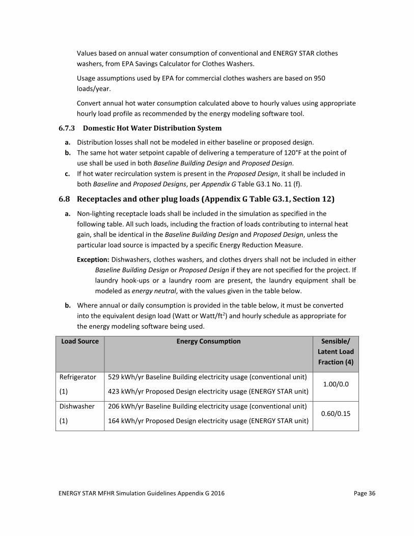
ENERGY STAR MFHR Simulation Guidelines Appendix G 2016 Page 36
Values based on annual water consumption of conventional and ENERGY STAR clothes
washers, from EPA Savings Calculator for Clothes Washers.
Usage assumptions used by EPA for commercial clothes washers are based on 950
loads/year.
Convert annual hot water consumption calculated above to hourly values using appropriate
hourly load profile as recommended by the energy modeling software tool.
6.7.3 Domestic Hot Water Distribution System
a. Distribution losses shall not be modeled in either baseline or proposed design.
b. The same hot water setpoint capable of delivering a temperature of 120°F at the point of
use shall be used in both Baseline Building Design and Proposed Design.
c. If hot water recirculation system is present in the Proposed Design, it shall be included in
both Baseline and Proposed Designs, per Appendix G Table G3.1 No. 11 (f).
6.8 Receptacles and other plug loads (Appendix G Table G3.1, Section 12)
a. Non-lighting receptacle loads shall be included in the simulation as specified in the
following table. All such loads, including the fraction of loads contributing to internal heat
gain, shall be identical in the Baseline Building Design and Proposed Design, unless the
particular load source is impacted by a specific Energy Reduction Measure.
Exception: Dishwashers, clothes washers, and clothes dryers shall not be included in either
Baseline Building Design or Proposed Design if they are not specified for the project. If
laundry hook-ups or a laundry room are present, the laundry equipment shall be
modeled as energy neutral, with the values given in the table below.
b. Where annual or daily consumption is provided in the table below, it must be converted
into the equivalent design load (Watt or Watt/ft2) and hourly schedule as appropriate for
the energy modeling software being used.
Load Source Energy Consumption Sensible/
Latent Load
Fraction (4)
Refrigerator
(1)
529 kWh/yr Baseline Building electricity usage (conventional unit)
423 kWh/yr Proposed Design electricity usage (ENERGY STAR unit) 1.00/0.0
Dishwasher
(1)
206 kWh/yr Baseline Building electricity usage (conventional unit)
164 kWh/yr Proposed Design electricity usage (ENERGY STAR unit) 0.60/0.15
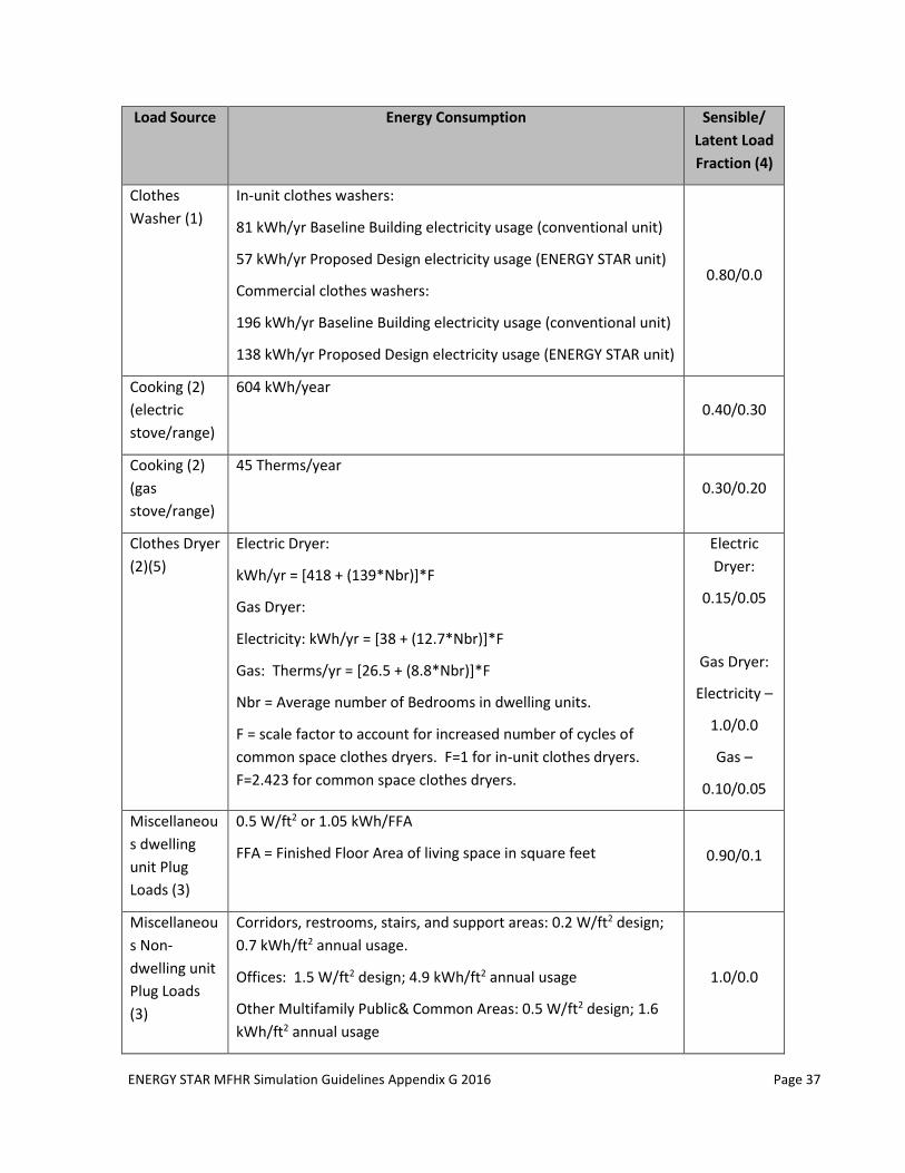
ENERGY STAR MFHR Simulation Guidelines Appendix G 2016 Page 37
Load Source Energy Consumption Sensible/
Latent Load
Fraction (4)
Clothes
Washer (1)
In-unit clothes washers:
81 kWh/yr Baseline Building electricity usage (conventional unit)
57 kWh/yr Proposed Design electricity usage (ENERGY STAR unit)
Commercial clothes washers:
196 kWh/yr Baseline Building electricity usage (conventional unit)
138 kWh/yr Proposed Design electricity usage (ENERGY STAR unit)
0.80/0.0
Cooking (2)
(electric
stove/range)
604 kWh/year
0.40/0.30
Cooking (2)
(gas
stove/range)
45 Therms/year
0.30/0.20
Clothes Dryer
(2)(5)
Electric Dryer:
kWh/yr = [418 + (139*Nbr)]*F
Gas Dryer:
Electricity: kWh/yr = [38 + (12.7*Nbr)]*F
Gas: Therms/yr = [26.5 + (8.8*Nbr)]*F
Nbr = Average number of Bedrooms in dwelling units.
F = scale factor to account for increased number of cycles of
common space clothes dryers. F=1 for in-unit clothes dryers.
F=2.423 for common space clothes dryers.
Electric
Dryer:
0.15/0.05
Gas Dryer:
Electricity –
1.0/0.0
Gas –
0.10/0.05
Miscellaneou
s dwelling
unit Plug
Loads (3)
0.5 W/ft2 or 1.05 kWh/FFA
FFA = Finished Floor Area of living space in square feet 0.90/0.1
Miscellaneou
s Non-
dwelling unit
Plug Loads
(3)
Corridors, restrooms, stairs, and support areas: 0.2 W/ft2 design;
0.7 kWh/ft2 annual usage.
Offices: 1.5 W/ft2 design; 4.9 kWh/ft2 annual usage
Other Multifamily Public& Common Areas: 0.5 W/ft2 design; 1.6
kWh/ft2 annual usage
1.0/0.0
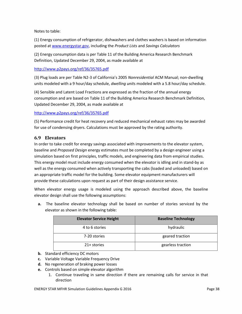
ENERGY STAR MFHR Simulation Guidelines Appendix G 2016 Page 38
Notes to table:
(1) Energy consumption of refrigerator, dishwashers and clothes washers is based on information
posted at www.energystar.gov, including the Product Lists and Savings Calculators
(2) Energy consumption data is per Table 11 of the Building America Research Benchmark
Definition, Updated December 29, 2004, as made available at
http://www.p2pays.org/ref/36/35765.pdf
(3) Plug loads are per Table N2-3 of California’s 2005 Nonresidential ACM Manual; non-dwelling
units modeled with a 9 hour/day schedule, dwelling units modeled with a 5.8 hour/day schedule.
(4) Sensible and Latent Load Fractions are expressed as the fraction of the annual energy
consumption and are based on Table 11 of the Building America Research Benchmark Definition,
Updated December 29, 2004, as made available at
http://www.p2pays.org/ref/36/35765.pdf
(5) Performance credit for heat recovery and reduced mechanical exhaust rates may be awarded
for use of condensing dryers. Calculations must be approved by the rating authority.
6.9 Elevators
In order to take credit for energy savings associated with improvements to the elevator system,
baseline and Proposed Design energy estimates must be completed by a design engineer using a
simulation based on first principles, traffic models, and engineering data from empirical studies.
This energy model must include energy consumed when the elevator is idling and in stand-by as
well as the energy consumed when actively transporting the cabs (loaded and unloaded) based on
an appropriate traffic model for the building. Some elevator equipment manufacturers will
provide these calculations upon request as part of their design assistance service.
When elevator energy usage is modeled using the approach described above, the baseline
elevator design shall use the following assumptions:
a. The baseline elevator technology shall be based on number of stories serviced by the
elevator as shown in the following table:
Elevator Service Height Baseline Technology
4 to 6 stories hydraulic
7-20 stories geared traction
21+ stories gearless traction
b. Standard efficiency DC motors c. Variable Voltage Variable Frequency Drive d. No regeneration of braking power losses e. Controls based on simple elevator algorithm
1. Continue traveling in same direction if there are remaining calls for service in that direction
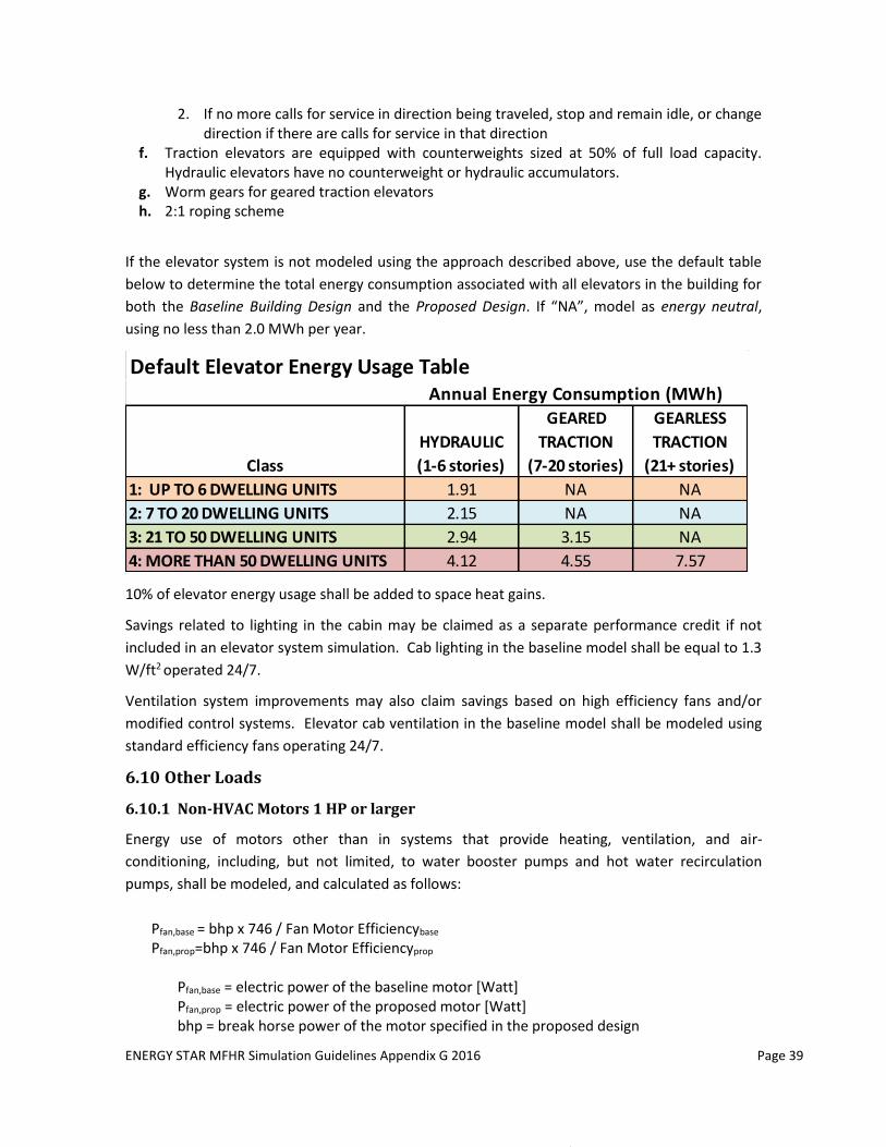
ENERGY STAR MFHR Simulation Guidelines Appendix G 2016 Page 39
2. If no more calls for service in direction being traveled, stop and remain idle, or change direction if there are calls for service in that direction
f. Traction elevators are equipped with counterweights sized at 50% of full load capacity. Hydraulic elevators have no counterweight or hydraulic accumulators.
g. Worm gears for geared traction elevators h. 2:1 roping scheme
If the elevator system is not modeled using the approach described above, use the default table
below to determine the total energy consumption associated with all elevators in the building for
both the Baseline Building Design and the Proposed Design. If “NA”, model as energy neutral,
using no less than 2.0 MWh per year.
Default Elevator Energy Usage Table
Class
HYDRAULIC
(1-6 stories)
GEARED
TRACTION
(7-20 stories)
GEARLESS
TRACTION
(21+ stories)
1: UP TO 6 DWELLING UNITS 1.91 NA NA
2: 7 TO 20 DWELLING UNITS 2.15 NA NA
3: 21 TO 50 DWELLING UNITS 2.94 3.15 NA
4: MORE THAN 50 DWELLING UNITS 4.12 4.55 7.57
Annual Energy Consumption (MWh)
10% of elevator energy usage shall be added to space heat gains.
Savings related to lighting in the cabin may be claimed as a separate performance credit if not
included in an elevator system simulation. Cab lighting in the baseline model shall be equal to 1.3
W/ft2 operated 24/7.
Ventilation system improvements may also claim savings based on high efficiency fans and/or
modified control systems. Elevator cab ventilation in the baseline model shall be modeled using
standard efficiency fans operating 24/7.
6.10 Other Loads
6.10.1 Non-HVAC Motors 1 HP or larger
Energy use of motors other than in systems that provide heating, ventilation, and air-
conditioning, including, but not limited, to water booster pumps and hot water recirculation
pumps, shall be modeled, and calculated as follows:
Pfan,base = bhp x 746 / Fan Motor Efficiencybase Pfan,prop=bhp x 746 / Fan Motor Efficiencyprop
Pfan,base = electric power of the baseline motor [Watt] Pfan,prop = electric power of the proposed motor [Watt] bhp = break horse power of the motor specified in the proposed design
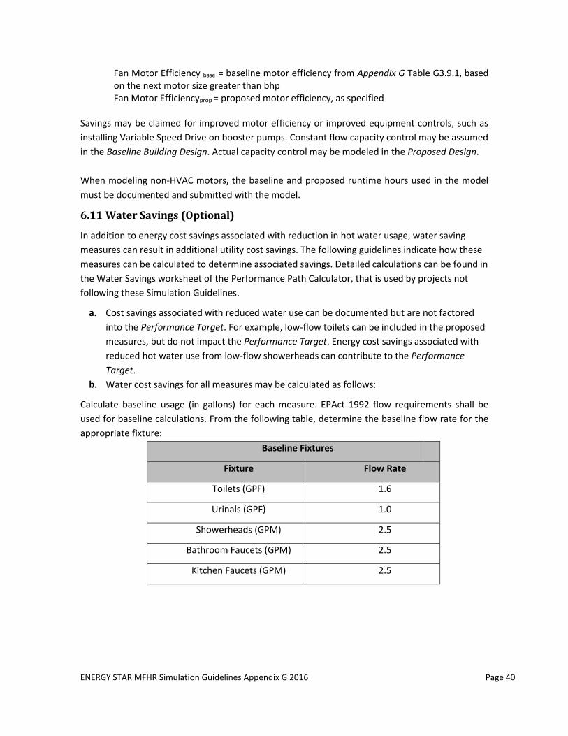
ENERGY STAR MFHR Simulation Guidelines Appendix G 2016 Page 40
Fan Motor Efficiency base = baseline motor efficiency from Appendix G Table G3.9.1, based on the next motor size greater than bhp Fan Motor Efficiencyprop = proposed motor efficiency, as specified
Savings may be claimed for improved motor efficiency or improved equipment controls, such as
installing Variable Speed Drive on booster pumps. Constant flow capacity control may be assumed
in the Baseline Building Design. Actual capacity control may be modeled in the Proposed Design.
When modeling non-HVAC motors, the baseline and proposed runtime hours used in the model
must be documented and submitted with the model.
6.11 Water Savings (Optional)
In addition to energy cost savings associated with reduction in hot water usage, water saving
measures can result in additional utility cost savings. The following guidelines indicate how these
measures can be calculated to determine associated savings. Detailed calculations can be found in
the Water Savings worksheet of the Performance Path Calculator, that is used by projects not
following these Simulation Guidelines.
a. Cost savings associated with reduced water use can be documented but are not factored
into the Performance Target. For example, low-flow toilets can be included in the proposed
measures, but do not impact the Performance Target. Energy cost savings associated with
reduced hot water use from low-flow showerheads can contribute to the Performance
Target.
b. Water cost savings for all measures may be calculated as follows:
Calculate baseline usage (in gallons) for each measure. EPAct 1992 flow requirements shall be
used for baseline calculations. From the following table, determine the baseline flow rate for the
appropriate fixture:
Baseline Fixtures
Fixture Flow Rate
Toilets (GPF) 1.6
Urinals (GPF) 1.0
Showerheads (GPM) 2.5
Bathroom Faucets (GPM) 2.5
Kitchen Faucets (GPM) 2.5
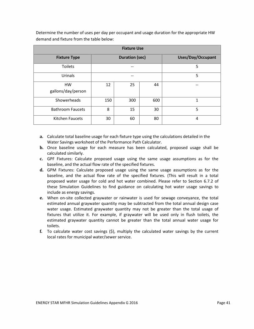
ENERGY STAR MFHR Simulation Guidelines Appendix G 2016 Page 41
Determine the number of uses per day per occupant and usage duration for the appropriate HW
demand and fixture from the table below:
Fixture Use
Fixture Type Duration (sec) Uses/Day/Occupant
Toilets -- 5
Urinals -- 5
HW
gallons/day/person
12 25 44 --
Showerheads 150 300 600 1
Bathroom Faucets 8 15 30 5
Kitchen Faucets 30 60 80 4
a. Calculate total baseline usage for each fixture type using the calculations detailed in the Water Savings worksheet of the Performance Path Calculator.
b. Once baseline usage for each measure has been calculated, proposed usage shall be calculated similarly.
c. GPF Fixtures: Calculate proposed usage using the same usage assumptions as for the baseline, and the actual flow rate of the specified fixtures.
d. GPM Fixtures: Calculate proposed usage using the same usage assumptions as for the baseline, and the actual flow rate of the specified fixtures. (This will result in a total proposed water usage for cold and hot water combined. Please refer to Section 6.7.2 of these Simulation Guidelines to find guidance on calculating hot water usage savings to include as energy savings.
e. When on-site collected graywater or rainwater is used for sewage conveyance, the total estimated annual graywater quantity may be subtracted from the total annual design case water usage. Estimated graywater quantity may not be greater than the total usage of fixtures that utilize it. For example, if graywater will be used only in flush toilets, the estimated graywater quantity cannot be greater than the total annual water usage for toilets.
f. To calculate water cost savings ($), multiply the calculated water savings by the current local rates for municipal water/sewer service.
ENERGY STAR MFHR Simulation Guidelines Appendix G 2016 Page 42
APPENDIX A: Referenced Standards and Data Sources (Informative)
ANSI/ASHRAE/IESNA Standard 90.1 -2016 Energy Standard for Buildings Except Low-Rise
Residential Buildings: Primary source document for Baseline Building Design features and
guidance for creating a performance-based evaluation of a proposed building’s energy features
(Appendix G).
ANSI/ASHRAE/IES Standard 90.1-2013 User’s Manual
ANSI/ASHRAE/IES Standard 90.1- 2016 Performance Rating Method Reference Manual, PNNL
Illuminating Engineering Society Lighting Handbook: handbook of lighting design published by
the Illuminating Engineering Society of North America (IESNA), www.iesna.org.
Air-conditioning, Heating, and Refrigeration Institute (AHRI): reference AHRI ratings to
determine seasonal efficiencies of heating and cooling systems, www.ahridirectory.org.
Energy Policy Act 1992 (EPACT 1992): federal legislation including provisions describing minimum
efficiencies for certain appliances and plumbing fixtures. The complete document can be found in
the Library of Congress website at http://thomas.loc.gov/cgi-bin/query/z?c102:H.R.776.ENR:
ASHRAE Standard 62.1-2007/10/13: Ventilation for Acceptable Indoor Air Quality: Provides
guidance for ventilation system design and other related building features to ensure acceptable
indoor air quality. Scope includes all buildings except low-rise residential.
ASHRAE Standard 62.2-2007/10/13: Ventilation and Acceptable Indoor Air Quality in Low Rise
Residential Buildings: Provides guidance for ventilation system design and other related building
features to ensure acceptable indoor air quality.