Embed Size (px)
Citation preview
Report on the investigation
of the failure of a mooring bollard from the
Class V passenger vessel
Star Clipper
resulting in a fatal accident at
St Katharine’s Pier, River Thames, London
on
2 May 2004
Marine Accident Investigation BranchCarlton HouseCarlton PlaceSouthampton
United Kingdom SO15 2DZ
Report No 3/2005February 2005
Extract from
The Merchant Shipping
(Accident Reporting and Investigation)
Regulations 1999 – Regulation 4:
The fundamental purpose of investigating an accident under these Regulations is todetermine its circumstances and the cause with the aim of improving the safety of lifeat sea and the avoidance of accidents in the future. It is not the purpose to apportionliability, nor, except so far as is necessary to achieve the fundamental purpose, toapportion blame.
NOTE
This report is not written with liability in mind and is not intended to be used in courtfor the purpose of litigation. It endeavours to identify and analyse the relevant safetyissues pertaining to the specific accident, and to make recommendations aimed atpreventing similar accidents in the future.
CONTENTSPage
GLOSSARY OF ABBREVIATIONS AND ACRONYMS
SYNOPSIS 1
SECTION 1 - FACTUAL INFORMATION 3
1.1 Particulars of Star Clipper and accident 31.2 Vessel operating routine 41.3 Narrative (all times are UTC + 1) 4
1.3.1 Schedule prior to accident 41.3.2 Effects and actions of other vessels 41.3.3 Star Clipper’s approach to St Katharine’s Pier 61.3.4 Bollard failure 81.3.5 Actions by Sarah Kathleen and Sarpedon 111.3.6 Immediate post-accident actions 11
1.4 MCA post-accident actions 121.4.1 MCA Prohibition Notice 12
1.5 Star Clipper – crew particulars 131.5.1 Captain 131.5.2 Mate 131.5.3 Stewardess 13
1.6 Description of vessel 131.7 Company and vessel history 16
1.7.1 Operating company history 161.7.2 Founder owner 161.7.3 Vessel history 161.7.4 Classification society 171.7.5 MCA inspection 17
1.8 Weather conditions 171.9 St Katharine’s Pier 17
1.9.1 General 171.9.2 Layout 171.9.3 CCTV 18
1.10 Description of failed mooring bollard 181.10.1 General observations 181.10.2 Dimensional information 18
1.11 History of mooring bollard changes 201.11.1 Build 201.11.2 Serco Denholm Ltd charter 201.11.3 CRE ownership 22
1.12 Owners’ responsibility to report defects/failures 231.13 Bollard repairs following failure on 9 April 2004 23
1.13.1 Background 231.13.2 Preparation for repair 251.13.3 Weld repair 25
1.14 Alweld - fabrication and welding company 261.14.1 Background 261.14.2 Welder’s experience 26
1.15 Star Clipper’s passenger access platform 261.15.1 Structure 261.15.2 Bollard mounting area damage 27
1.16 Mooring rope 271.17 Independent reports 28
1.17.1 Bollard, bollard insert plate, weld and support structure 281.17.2 Polypropylene mooring rope and related possible bollard
trajectories 281.17.3 Paint sample deposits on the bollard, insert plate and from
the accident site 281.18 Re-enactment 291.19 Operating company safety organisation 301.20 River Thames’s piers - passenger safety arrangements 30
SECTION 2 - ANALYSIS 31
2.1 Aim 312.2 Bollard replacement 312.3 Reporting of defects 312.4 MCA inspection and survey 322.5 Suitability of the bollard supporting structure 322.6 Weld repair failure and insert plate material selection 32
2.6.1 Material selection 332.6.2 Weld repair considerations 332.6.3 Shear forces required for failure 33
2.7 Vessel operation 342.7.1 Approach to St Katharine’s Pier 342.7.2 Coming alongside 342.7.3 Mooring procedures 35
2.8 Bollard trajectory 362.9 Rope selection 372.10 Pier safety 372.11 Fatigue 372.12 PLA and RNLI reactions 37
SECTION 3 - CONCLUSIONS 38
3.1 Safety issues 38
SECTION 4 - ACTION TAKEN 39
4.1 Maritime and Coastguard Agency 394.2 Port of London Authority 394.3 Collins River Enterprises 394.4 St Katharine’s Dock Harbourmaster 39
SECTION 5 - RECOMMENDATIONS 40
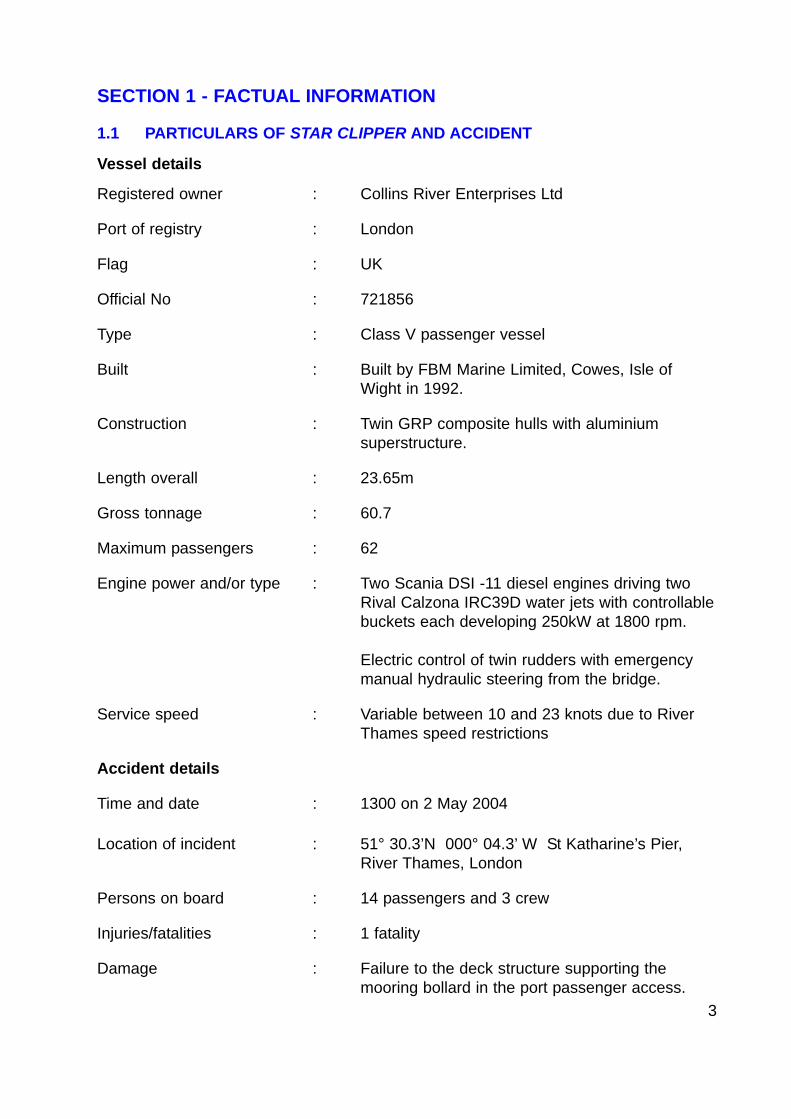
Figure 1 - View of Tower Bridge north bank shore arch
Figure 2 - Port Passenger Access - mate’s position for coming alongside
Figure 3 - Passenger access - stainless steel mooring bollard
Figure 4 - Position of vessels and pier gates at St Katharine’s Pier
Figure 5 - Mooring rope - pin hitch arrangement
Figure 6 - Displaced stainless steel bollard and insert plate
Figure 7 - Position of missing bollard on board Star Clipper
Figure 8 - Approximate positions of the injured person, bollard andmooring rope
Figure 9 - General arrangement - profile
Figure 10 - General arrangement - plan
Figure 11 - View of bridge controls (port)
Figure 12 - View of bridge contols (starboard)
Figure 13 - Layout of St Katharine’s Pier
Figure 14 - Location of red and white paint deposits on bollardarrangement, and insert plate deformation
Figure 15 - Illustration of difficult access to the forward bollards
Figure 16 - View of hollow aluminium bollard
Figure 17 - Example of failed MkI bollard
Figure 18 - Failure mechanism of bollard - 9 April 2004
Figure 19 - 6mm baseplate and fixing arrangements
Figure 20 - Passenger access platform - structural arrangement
Figure 21 - Casualty position prior to accident – plan view of pier
Figure 22 - Casualty position prior to accident - end view of pier
Figure 23 - Impact damage to bankside safety fencing
Annex A - MCA Prohibition Notice dated 2 May 2004 and ProhibitionNotice Addendum dated 3 May 2004
Annex B - Passenger Certificate and Domestic Safety ManagementCertificate dated 18 February 2004
Annex C - The Test House Report – T40821 dated 3 June 2004. LaboratoryReport Examination of a Fractured Bollard Mounting Plate Weldand Associated Material from the Thames River Craft StarClipper
Annex D - Tension Technology International Ltd – Report TTI-NOH-2004-274 dated 4 August 2004 – “Final Report on the Examinationand Tensile Testing of a Polypropylene Rope Strop, andCalculations to Establish the Likely Rope Stored EnergyInvolved in the Vessel Bollard Failure of the Star Clipper”
Annex E - Passenger Ship Construction Classes III to VI(A) – Instructionsfor the Guidance of Surveyors
Annex F - Merchant Shipping Notice - M718
Annex G - Marine Information Note - MIN 176 (M+F) - Safety Alert - MooringCleat Failures
Annex H - MCA (south-east district) - instruction to check bollard anddeck connections on Class V passenger vessels dated 10 May2004
Annex I - PLA instruction to check - instruction to check bollard and deckconnections on vessels carrying 12 passengers or less
Annex J - Operating procedure - TCOP 021 and related risk assessmentdated 3 May 2004
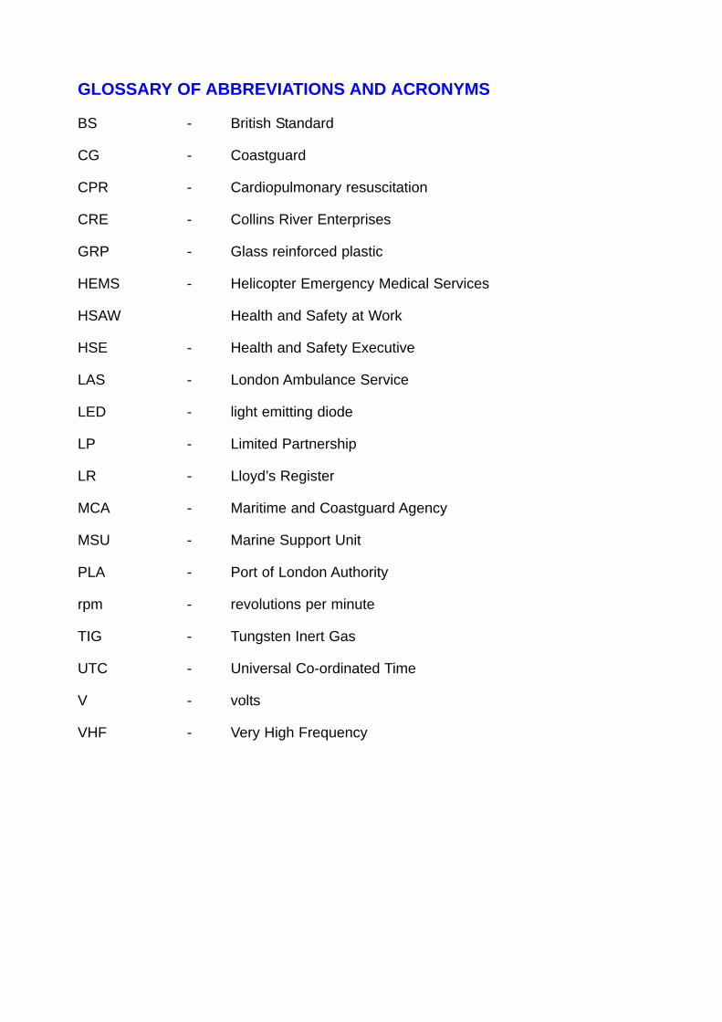
GLOSSARY OF ABBREVIATIONS AND ACRONYMS
BS - British Standard
CG - Coastguard
CPR - Cardiopulmonary resuscitation
CRE - Collins River Enterprises
GRP - Glass reinforced plastic
HEMS - Helicopter Emergency Medical Services
HSAW Health and Safety at Work
HSE - Health and Safety Executive
LAS - London Ambulance Service
LED - light emitting diode
LP - Limited Partnership
LR - Lloyd’s Register
MCA - Maritime and Coastguard Agency
MSU - Marine Support Unit
PLA - Port of London Authority
rpm - revolutions per minute
TIG - Tungsten Inert Gas
UTC - Universal Co-ordinated Time
V - volts
VHF - Very High Frequency
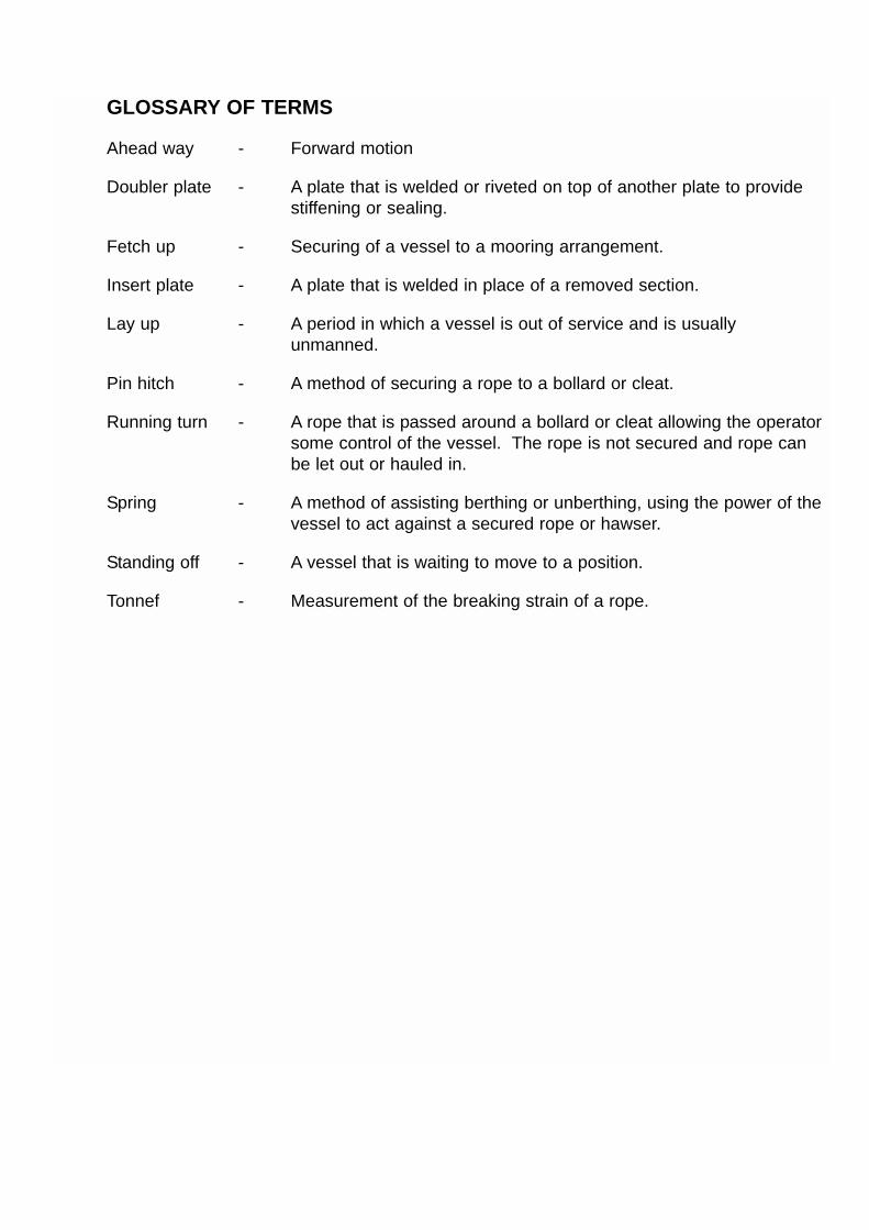
GLOSSARY OF TERMS
Ahead way - Forward motion
Doubler plate - A plate that is welded or riveted on top of another plate to providestiffening or sealing.
Fetch up - Securing of a vessel to a mooring arrangement.
Insert plate - A plate that is welded in place of a removed section.
Lay up - A period in which a vessel is out of service and is usuallyunmanned.
Pin hitch - A method of securing a rope to a bollard or cleat.
Running turn - A rope that is passed around a bollard or cleat allowing the operatorsome control of the vessel. The rope is not secured and rope canbe let out or hauled in.
Spring - A method of assisting berthing or unberthing, using the power of thevessel to act against a secured rope or hawser.
Standing off - A vessel that is waiting to move to a position.
Tonnef - Measurement of the breaking strain of a rope.

SYNOPSIS
At approximately 1258, on Sunday 2 May 2004, a mooringbollard was torn from the deck of the Class V fast catamaran,Star Clipper, striking a female passenger waiting to board.The lady’s injuries were fatal.
Owned by Collins River Enterprises (CRE) Ltd, Star Clipperprovides a commuter shuttle ferry service on the RiverThames between Masthouse Terrace Pier and Savoy Pier.On the day of the accident, she was making a routineapproach onto St Katharine’s Pier, having previously called atBankside Pier. The weather conditions were good, it washigh water and there was very little tidal stream. There was
negligible swell, but the wash from small craft in the vicinity caused surfacedisturbance and movement of St Katharine’s Pier.
Between 30 and 35 people were on the pier waiting for Star Clipper and other riverservices. As the vessel made the approach, her mate, standing at the port passengerentrance, passed the eye of a polypropylene berthing rope over a pier bollard andsecured it loosely onto one of the vessel’s bollards. The captain manoeuvred StarClipper to align with the pier and vessel passenger gates. When the vessel was about1.5m from the pier, the rope was secured and slight ahead power maintained to bringher alongside.
Just prior to coming alongside, Star Clipper’s mooring bollard was torn from the deckand was catapulted over the 1.1m pier safety fence. It struck one of the waitingpassengers, causing fatal injuries.
The captain of Star Clipper immediately alerted Woolwich Radio and requested theattendance of an ambulance. The injured lady, who was with her husband, was initiallygiven first-aid by waiting passengers and soon afterwards by the crew of the PLAharbour services launch Westbourne. The Tower Pier lifeboat, which had beenactivated, arrived on the scene at approximately 1306 and its crew took over andbegan CPR. Very soon, the London Ambulance Service paramedics arrived, followedby the HEMS doctor. The lady was transferred to the Royal London Hospital at 1358.She died from her injuries at 1434.
The mooring bollards fitted in Star Clipper’s passenger access areas were not part ofthe original build specification. The design of the solid stainless steel bollard and baseplate that failed on 2 May had evolved empirically through a series of modifications inreaction to earlier, less catastrophic, failures. The MCA had not been informed ofthese failures, nor was it consulted over the subsequent proposed modifications.
On 9 April 2004, the same bollard had been torn from Star Clipper’s deck. Theresulting repair work failed catastrophically, allowing the bollard and attached insertplate to be catapulted into the waiting passengers less than 1 month later.
1

2
In an effort to prevent a repeat of this tragic accident, the MAIB has issued severalrecommendations. The recommendations focus on the need for the MCA to checkmooring fittings during its periodic surveys, and for the owners to seek professionaladvice when considering repairs or changes to fittings that are critical to the vessel’ssafety, to ensure these are undertaken to an appropriate standard.
Star Clipper
3
SECTION 1 - FACTUAL INFORMATION
1.1 PARTICULARS OF STAR CLIPPER AND ACCIDENT
Vessel details
Registered owner : Collins River Enterprises Ltd
Port of registry : London
Flag : UK
Official No : 721856
Type : Class V passenger vessel
Built : Built by FBM Marine Limited, Cowes, Isle ofWight in 1992.
Construction : Twin GRP composite hulls with aluminiumsuperstructure.
Length overall : 23.65m
Gross tonnage : 60.7
Maximum passengers : 62
Engine power and/or type : Two Scania DSI -11 diesel engines driving twoRival Calzona IRC39D water jets with controllablebuckets each developing 250kW at 1800 rpm.
Electric control of twin rudders with emergencymanual hydraulic steering from the bridge.
Service speed : Variable between 10 and 23 knots due to RiverThames speed restrictions
Accident details
Time and date : 1300 on 2 May 2004
Location of incident : 51° 30.3’N 000° 04.3’ W St Katharine’s Pier,River Thames, London
Persons on board : 14 passengers and 3 crew
Injuries/fatalities : 1 fatality
Damage : Failure to the deck structure supporting themooring bollard in the port passenger access.
4
1.2 VESSEL OPERATING ROUTINE
Collins River Enterprises operates Star Clipper on a River Thames commuterservice. The weekday service calls at Masthouse Terrace, Greenland, CanaryWharf, St Katharine’s, London Bridge, City, Bankside, Blackfriars and SavoyPiers and takes approximately 25 minutes. An additional single early morningand evening stop is scheduled at Greenwich Pier. At weekends, and duringpublic holidays, the number of stops is reduced to six, with London Bridge andBlackfriars Piers being omitted from the schedule.
1.3 NARRATIVE (ALL TIMES ARE UTC + 1)
1.3.1 Schedule prior to accident
At 0900 on 2 May 2004, the captain and mate of Star Clipper arrived at theovernight mooring at Greenland Pier to prepare the vessel for service. Thestewardess joined them at 1000 and, following re-fuelling, Star Clipper sailed at1030 to commence the usual weekend commuter service.
The first return trip was uneventful and took about 1 hour. The vessel thenremained alongside Masthouse Pier from 1130 until 1210 at which time thewestbound service resumed.
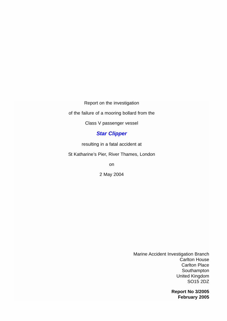
At approximately 1255, Star Clipper arrived, on schedule, at Bankside Pier. Thevessel left soon afterwards with 14 passengers onboard, and made her waytowards St Katharine’s Pier via the Tower Bridge north bank shore arch (Figure 1).
1.3.2 Effects and actions of other vessels
As Star Clipper entered the arch, her captain started to reduce the engine powerto approximately 1000 rpm, equating to a speed of approximately 6 - 7 knots.Star Clipper continued to reduce speed as she passed under the arch. At thesame time, the 35m, pleasure vessel Sarpedon was exiting the same arch. Shewas making a 3 - 4 knot approach onto St Katharine’s Pier in preparation forpicking up passengers for the Greenwich Pier service.
The 20m open topped sightseeing vessel, Sarah Kathleen, with 111 passengersonboard, was berthing at the eastern end of St Katharine’s Pier. Her positionallowed sufficient room for Sarpedon to go alongside St Katharine’s Pier. BothSarpedon and Sarah Kathleen are owned by Crown River Cruises based atBlackfriars Pier.
As it was high tide, a number of other small craft were also in the vicinity waitingto enter St Katharine’s Dock, which is near the pier.
Conscious that Star Clipper is considerably more manoeuvrable than Sarpedon,Star Clipper’s captain decided to overtake Sarpedon as he exited the arch. Hisinitial intention was to berth just astern of Sarah Kathleen to leave sufficient
5
room for Sarpedon to also go alongside St Katharine’s Pier. However, he didnot inform the mate of this. Although the overtaking manoeuvre was notunusual, Sarpedon’s captain was surprised that he was not informed by VHFtransmission of Star Clipper’s intentions. The manoeuvre caused Sarpedon togo astern and “stand off” when about 40 - 50m from the pier.
Having noticed that Star Clipper was approaching, a female passenger madeher way down to the pier with her husband, to join the other 30 - 35 passengerswho were waiting in small groups.
At 1258, Sarah Kathleen was fully secured to the pier. Her captain informed hispassengers that Sarpedon was about to come alongside for the continuationservice to Greenwich. While making his public address, he turned to face TowerBridge and was surprised to see Star Clipper making her final approach to thepier and Sarpedon “standing off”. This was the first time he became aware thatStar Clipper was in the vicinity.
In the meantime, Sarah Kathleen’s 45 passengers began to disembark at StKatharine’s Pier.
View of Tower Bridge north bank shore arch
Figure 1

6
1.3.3 Star Clipper’s approach to St Katharine’s Pier
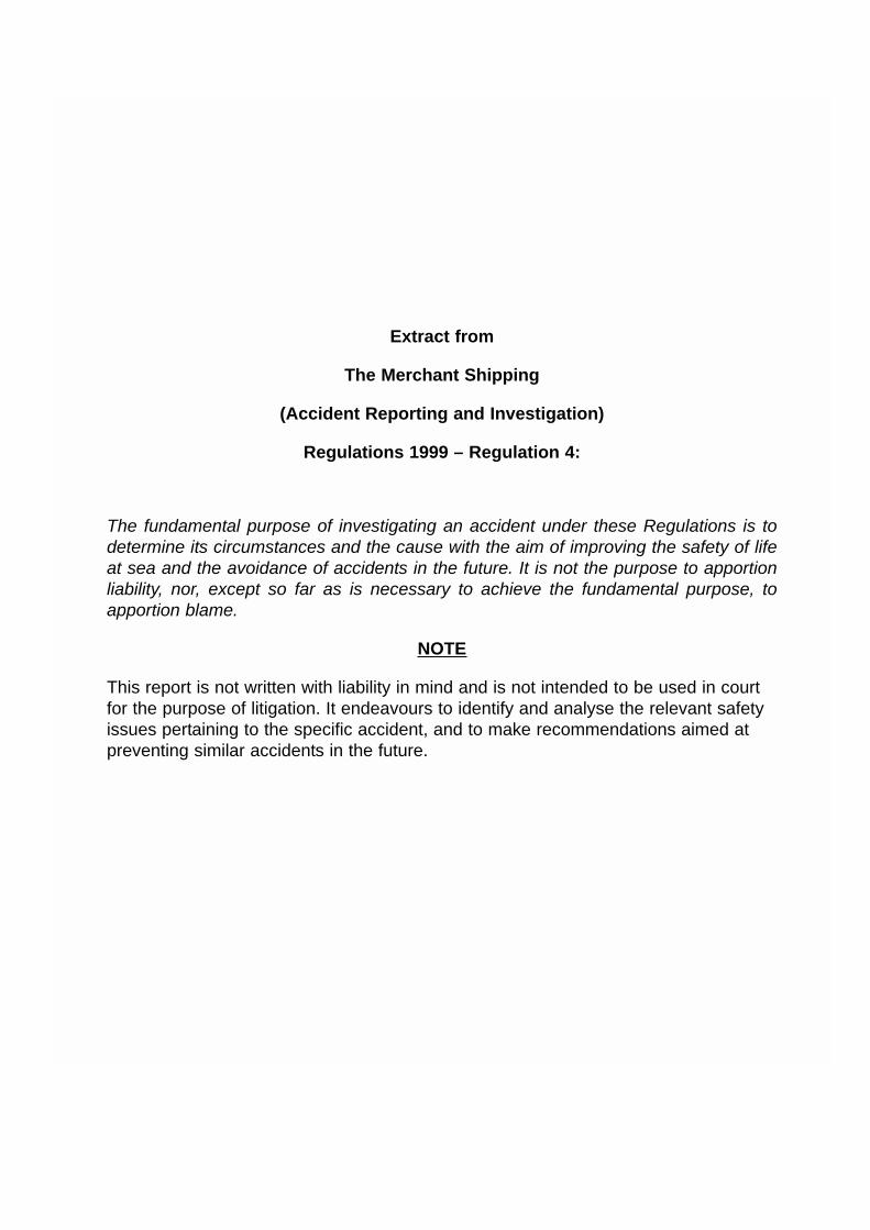
At 1259, having overtaken Sarpedon, Star Clipper made the final approach to StKatharine’s Pier. Her mate was standing in the port passenger access with themooring rope in his hand (Figure 2). The stewardess was inside the passengercabin. Both port and starboard cabin doors, which gave access to thepassenger embarkation platforms, were closed.
The engine power was reduced, and the captain manoeuvred the vessel withthe water jet controls to make a normal, shallow approach, with the port bowslightly towards the pier. As the vessel neared the pier passenger gate, almostall ahead way had been taken off.
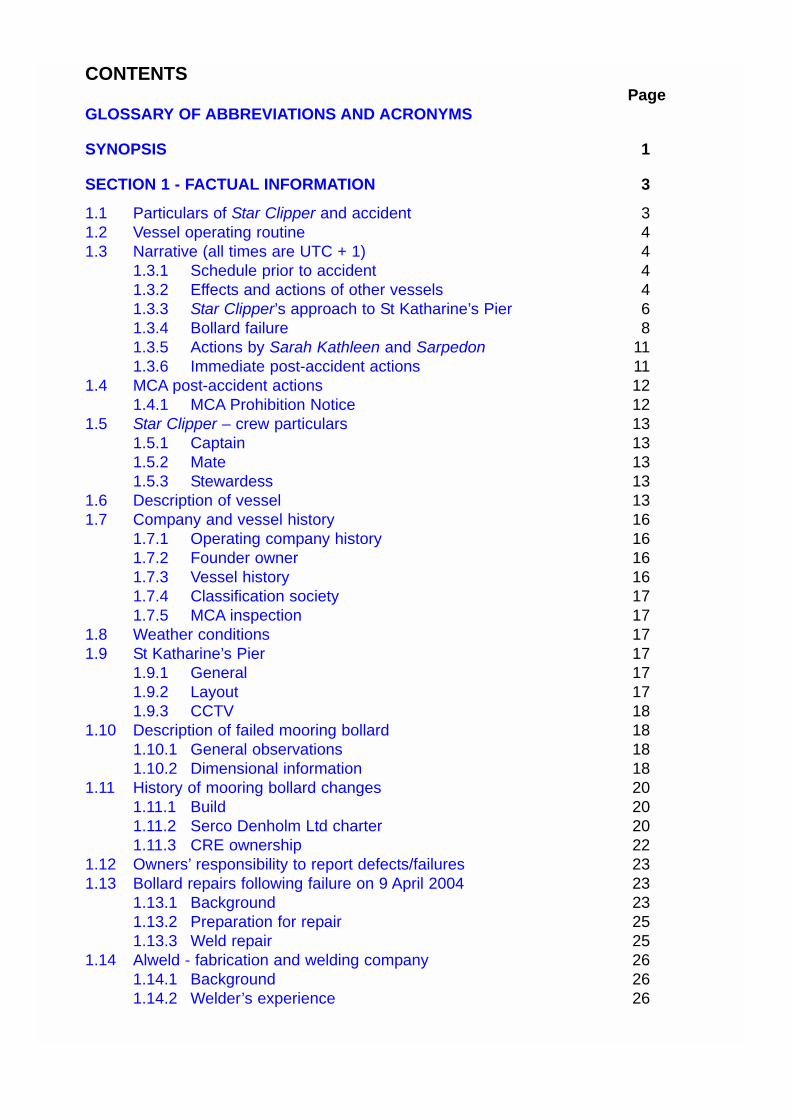
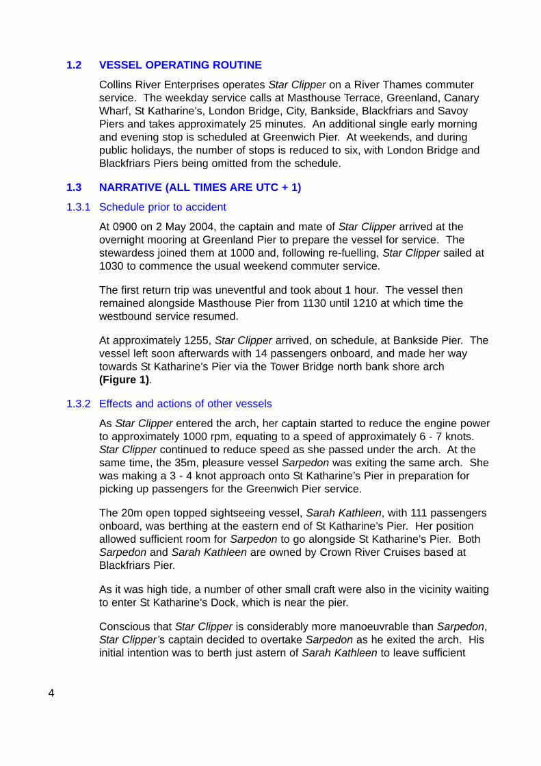
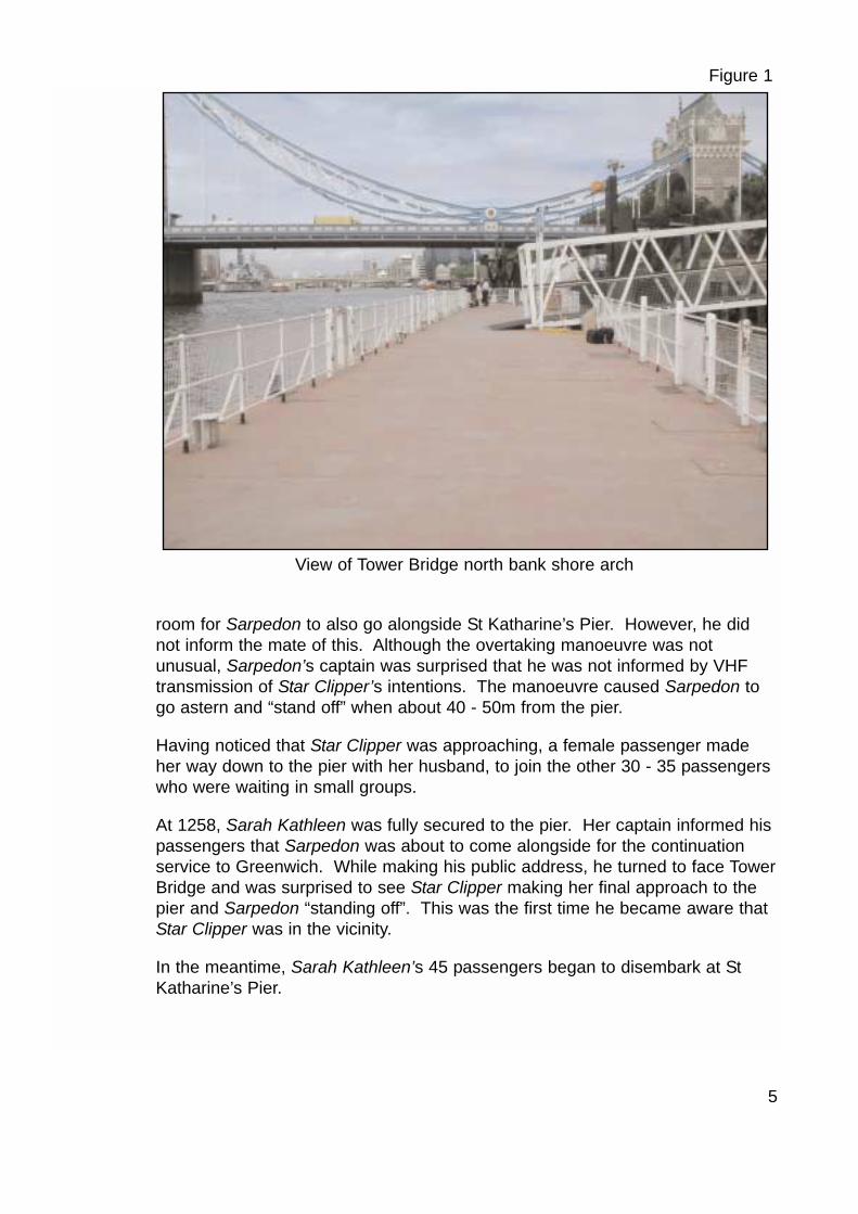
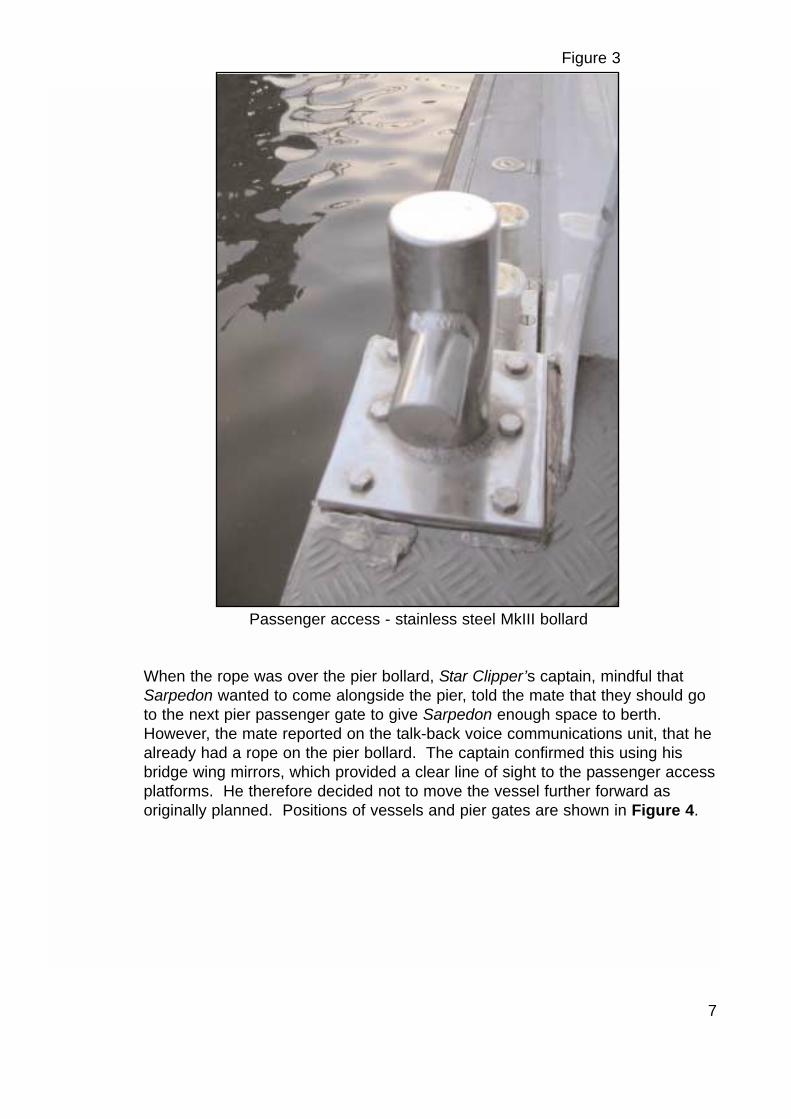
When Star Clipper was about 3 metres from the pier, her mate threw the eye ofthe polypropylene mooring rope over a pier bollard. Content that the eye wassecure, he then took a “running turn” around the port after stainless steelmooring bollard, located in the port passenger access recess. (Thearrangement at Figure 3 shows the position of the starboard bollard, which wasidentical to that on the port side prior to failure.) The “turn” around the bollardallowed the mate to let rope out as the vessel aligned with the pier passengergate.
Port passenger access - mate’s position for coming alongside
Figure 2
7
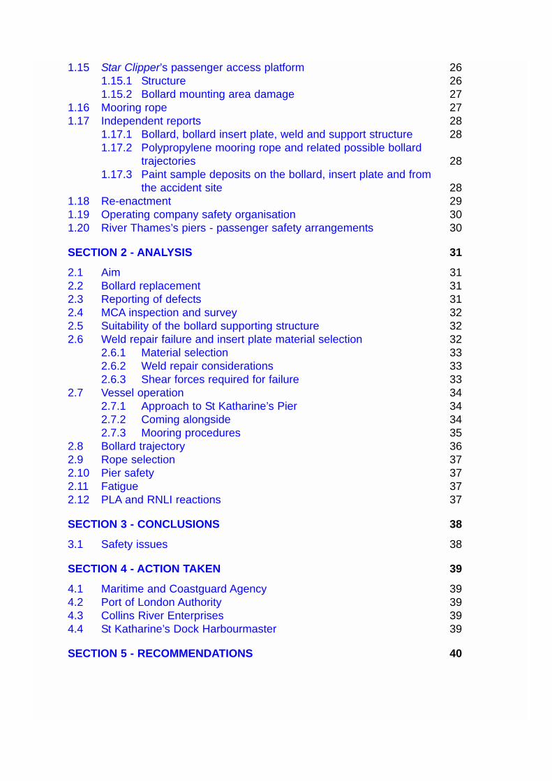
When the rope was over the pier bollard, Star Clipper’s captain, mindful thatSarpedon wanted to come alongside the pier, told the mate that they should goto the next pier passenger gate to give Sarpedon enough space to berth.However, the mate reported on the talk-back voice communications unit, that healready had a rope on the pier bollard. The captain confirmed this using hisbridge wing mirrors, which provided a clear line of sight to the passenger accessplatforms. He therefore decided not to move the vessel further forward asoriginally planned. Positions of vessels and pier gates are shown in Figure 4.
Passenger access - stainless steel MkIII bollard
Figure 3

8
1.3.4 Bollard failure
When Star Clipper was about 1.5m from the pier, the mate judged that about2.6m of slack rope was required to allow her to align with the pier passengergate. He secured the rope onto the vessel’s bollard with a “pin hitch” (Figure5). This action is known as the “fetch up”.
Meanwhile, the captain had the propulsion water jet controls in the “just ahead”position as indicated by two bars on his positional LED indicators with hisengines set at about 800 rpm. This setting provided sufficient power to bringthe vessel alongside and to counteract the wash from the engines of SarahKathleen, which was moored ahead. The mate, having secured the rope,dropped the free end to the deck and prepared to open the passenger gatesready for disembarkation.
Diagramatic representation of the relative positions of vesselsand casualty at the time of the accident (Not to scale)
Figure 4
Sarah Kathleen
Star Clipper
Passenger gates
Position of mate
Pier bollard inuse at time ofaccident
Approximateposition ofcasualty

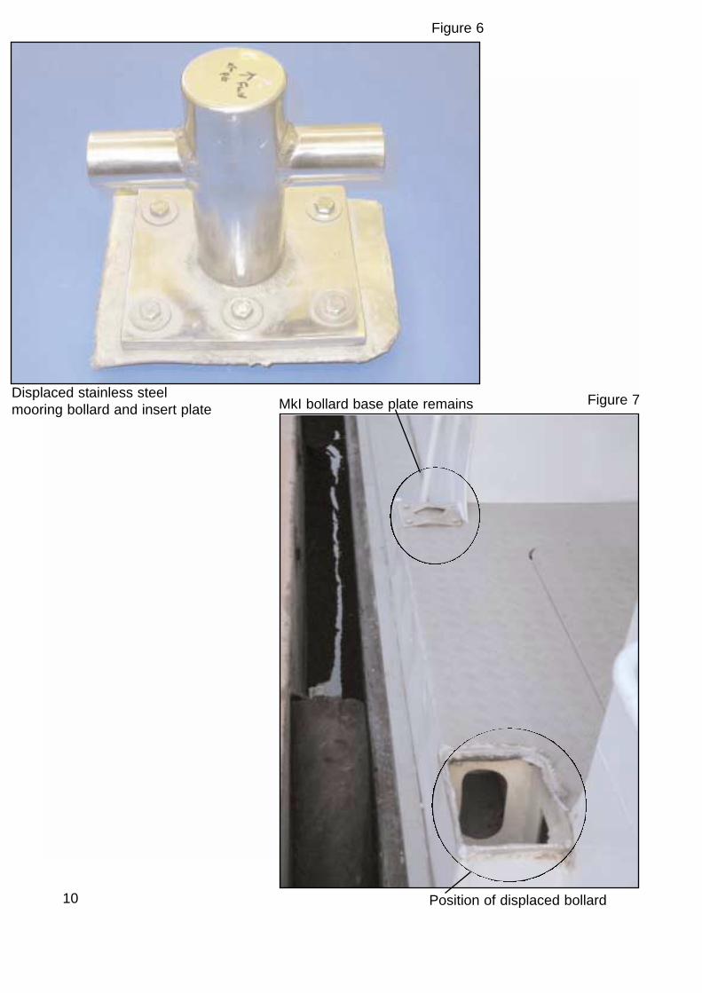
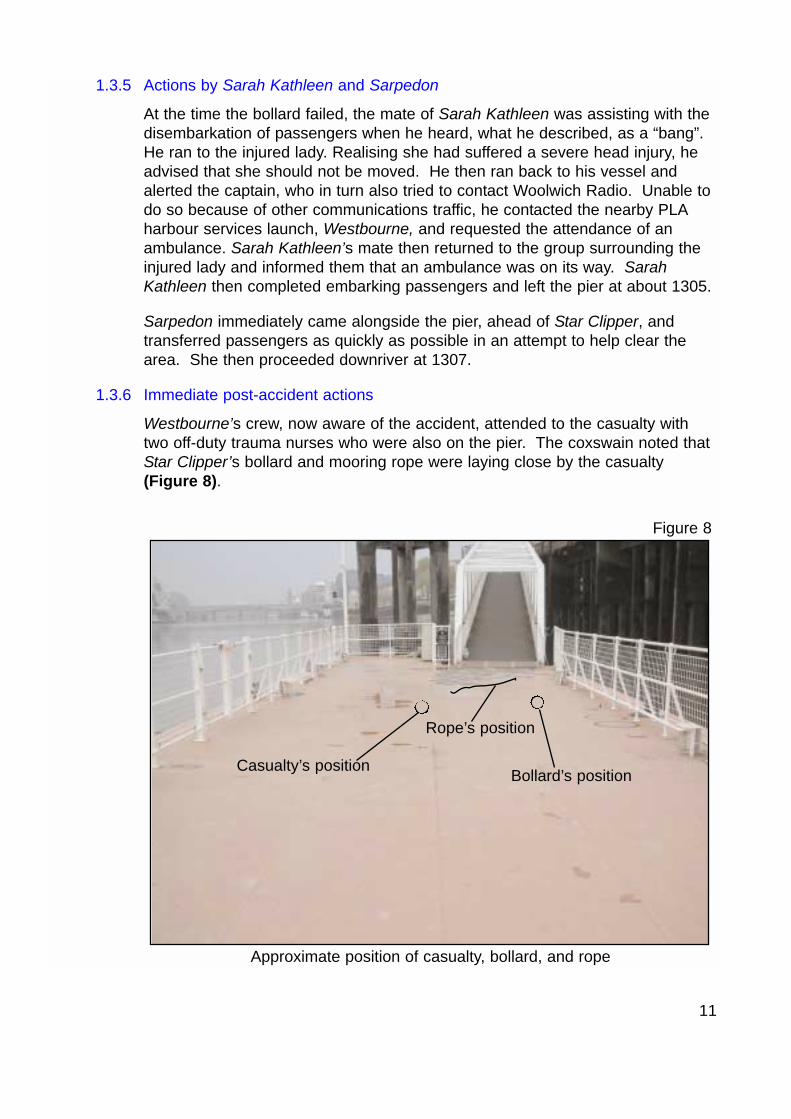
At 1300, when Star Clipper was just under 1m from the pier edge, the mooringbollard and supporting insert plate (Figure 6) were ripped from the deck andcatapulted over the 1.1m safety fence, into a group of waiting passengers. Themooring rope, having become detached from both the pier and vessel’s mooringbollards, was reported to have “snaked” through the air, and landed among thepassengers. At the same time, the mate looked down at the passenger accessplatform and saw a hole where the bollard had previously been (Figure 7). Hethen looked down the pier and saw a female passenger laying approximately2.13m from the pier bollard position. She was surrounded by other waitingpassengers. As the bollard failed, the vessel moved about 1m along the pierwhere the captain held her in position using her engines.
As soon as he saw the casualty, the mate rushed over to her. He saw that shewas badly injured and concluded that the bollard had hit her. The mate did notnotice the position of the bollard or mooring rope at that time. Now in shock, hereturned to Star Clipper immediately, and informed the captain of the situation.
The captain contacted Woolwich Radio on VHF channel 14 requesting theattendance of an ambulance. Afterwards, the mate secured the vesselalongside with a replacement rope. He provided towels for the injured lady, asrequested by her husband, and attended to his passengers.
9
Mooring rope ‘pin hitch’ arrangement
Figure 5
10
Figure 6
Position of displaced bollard
Figure 7MkI bollard base plate remainsDisplaced stainless steelmooring bollard and insert plate
11
1.3.5 Actions by Sarah Kathleen and Sarpedon
At the time the bollard failed, the mate of Sarah Kathleen was assisting with thedisembarkation of passengers when he heard, what he described, as a “bang”.He ran to the injured lady. Realising she had suffered a severe head injury, headvised that she should not be moved. He then ran back to his vessel andalerted the captain, who in turn also tried to contact Woolwich Radio. Unable todo so because of other communications traffic, he contacted the nearby PLAharbour services launch, Westbourne, and requested the attendance of anambulance. Sarah Kathleen’s mate then returned to the group surrounding theinjured lady and informed them that an ambulance was on its way. SarahKathleen then completed embarking passengers and left the pier at about 1305.
Sarpedon immediately came alongside the pier, ahead of Star Clipper, andtransferred passengers as quickly as possible in an attempt to help clear thearea. She then proceeded downriver at 1307.
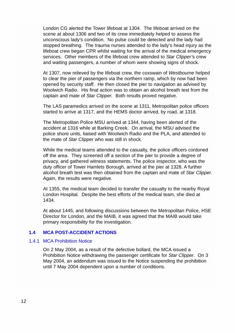
1.3.6 Immediate post-accident actions
Westbourne’s crew, now aware of the accident, attended to the casualty withtwo off-duty trauma nurses who were also on the pier. The coxswain noted thatStar Clipper’s bollard and mooring rope were laying close by the casualty(Figure 8).
Approximate position of casualty, bollard, and rope
Figure 8
Casualty’s position Bollard’s position
Rope’s position
12
London CG alerted the Tower lifeboat at 1304. The lifeboat arrived on thescene at about 1306 and two of its crew immediately helped to assess theunconscious lady’s condition. No pulse could be detected and the lady hadstopped breathing. The trauma nurses attended to the lady’s head injury as thelifeboat crew began CPR whilst waiting for the arrival of the medical emergencyservices. Other members of the lifeboat crew attended to Star Clipper’s crewand waiting passengers, a number of whom were showing signs of shock.
At 1307, now relieved by the lifeboat crew, the coxswain of Westbourne helpedto clear the pier of passengers via the northern ramp, which by now had beenopened by security staff. He then closed the pier to navigation as advised byWoolwich Radio. His final action was to obtain an alcohol breath test from thecaptain and mate of Star Clipper. Both results proved negative.
The LAS paramedics arrived on the scene at 1311, Metropolitan police officersstarted to arrive at 1317, and the HEMS doctor arrived, by road, at 1318.
The Metropolitan Police MSU arrived at 1344, having been alerted of theaccident at 1316 while at Barking Creek. On arrival, the MSU advised thepolice shore units, liaised with Woolwich Radio and the PLA, and attended tothe mate of Star Clipper who was still in shock.
While the medical teams attended to the casualty, the police officers cordonedoff the area. They screened off a section of the pier to provide a degree ofprivacy, and gathered witness statements. The police inspector, who was theduty officer of Tower Hamlets Borough, arrived at the pier at 1328. A furtheralcohol breath test was then obtained from the captain and mate of Star Clipper.Again, the results were negative.
At 1355, the medical team decided to transfer the casualty to the nearby RoyalLondon Hospital. Despite the best efforts of the medical team, she died at1434.
At about 1445, and following discussions between the Metropolitan Police, HSEDirector for London, and the MAIB, it was agreed that the MAIB would takeprimary responsibility for the investigation.
1.4 MCA POST-ACCIDENT ACTIONS
1.4.1 MCA Prohibition Notice
On 2 May 2004, as a result of the defective bollard, the MCA issued aProhibition Notice withdrawing the passenger certificate for Star Clipper. On 3May 2004, an addendum was issued to the Notice suspending the prohibitionuntil 7 May 2004 dependent upon a number of conditions.
The conditions banned the use of the amidships (passenger access) bollardsand advised other safety measures to be adopted to safeguard both crew andpassengers. They also required a risk assessment to be undertaken on therevised mooring arrangements. Details of the proposed structural changes tobe undertaken prior to the re-instatement of the midships bollards were alsorequired. A copy of the Prohibition Notice and Addendum is at Annex A.
1.5 STAR CLIPPER – CREW PARTICULARS
1.5.1 Captain
The captain held a full Waterman’s licence (No 73339) which was gained in May1994. He also held a Large Passenger Vessel endorsement to his licence,granted by Waterman’s Hall in March 1998. An experienced mariner, he workedwith his previous employer, a River Thames pleasure boat company, for 9 years.He also worked on the Clipper vessels when this company operated on theRiver Thames as part of the now defunct London River Bus Company.
The captain joined CRE in January 2004 when the company’s operationsmanager assessed his suitability for the position of captain during a 2 weektraining period.
1.5.2 Mate
The mate has worked for CRE for 2 years. The company is sponsoring him toundertake his 5-year Waterman’s apprenticeship. In March 2004 he gained hisPLA Grade 2 qualification in seamanship and chartwork, in addition to themandatory sea survival, VHF, first-aid and fire-fighting qualifications. On 24 May2004, he was awarded his Provisional Waterman’s Licence, which allows him tobe in charge of vessels carrying no more than 12 passengers.
1.5.3 Stewardess
The Polish stewardess has worked for CRE for 4 months. She had limitedmarine experience, but received appropriate training and assessment beforeundertaking her role.
1.6 DESCRIPTION OF VESSEL
Star Clipper is a 23.65m, Hydro Cat class catamaran built in 1992. She is aClass V passenger vessel and is certified to carry a maximum of 62passengers, with a minimum of 2 crew in daylight hours and 3 crew at night.
The twin GRP composite hulls are connected by two aluminium cross beamswhich support the aluminium passenger cabin. Each of the hulls is fitted with aScania DS1-11 diesel engine that drives a Rival Calzona IRC39D water jetpropulsion unit. Each water jet produces 250kW at 1800 rpm.
13
The main engine alternators charge two banks of 24V batteries, each of 200ampere hours. One bank provides normal vessel electrical services, the secondbattery bank is used for emergency supply purposes.
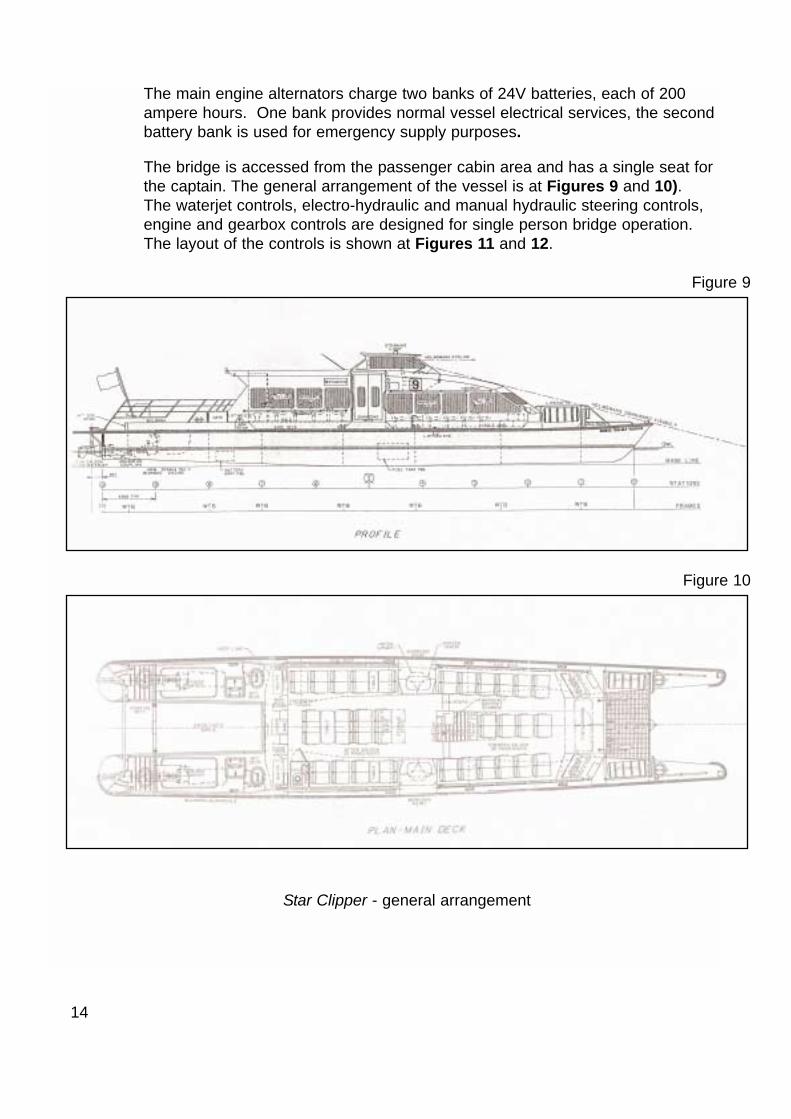
The bridge is accessed from the passenger cabin area and has a single seat forthe captain. The general arrangement of the vessel is at Figures 9 and 10).The waterjet controls, electro-hydraulic and manual hydraulic steering controls,engine and gearbox controls are designed for single person bridge operation.The layout of the controls is shown at Figures 11 and 12.
14
Star Clipper - general arrangement
Figure 9
Figure 10

15
Port side bridge controls
Figure 11Rev counterAlarm panelPort steeringindicator
Jet positionindicators
Backupsteering
Fire pumpBilge pumpSpeed selector switch
Port jetcontrol
Hydraulicsteering
control
Safetyannouncementbutton
Starboard side bridge controls
Figure 12Starboard steeringindicator
Compass
Ship’s horn
Starboardgearboxcontrol
Port gearboxcontrol
Starboard revcounter
Engine start button Engine stop button Port and starboardengine revs controls
Starboard jet control
1.7 COMPANY AND VESSEL HISTORY
1.7.1 Operating company history
Collins River Enterprises (CRE) Ltd, operating as Thames Clippers, wasestablished in May 1999 and has approximately 40 employees. The first of thevessels, Storm Clipper, was purchased in February 1999 and was refitted for theinitial six stop Thames commuter service between Greenland and Savoy Piers.
Two other vessels of the same class were subsequently purchased and refitted,Sky Clipper in September 2001 and Star Clipper in July 2003. With thepurchase of these vessels, the commuter service was extended to operatebetween Masthouse Terrace and Savoy Piers.
The company also owns and operates Hurricane Clipper, a large 220 passengercommuter service catamaran. A fifth vessel, managed by, but not owned by, thecompany, operates between Hilton Docklands and Canary Wharf piers.
1.7.2 Founder owner
The founder and owner of CRE is also the company’s marine operationsdirector, and has been working on the River Thames for 19 years. He is a fullylicensed Waterman and has a number of years’ experience as a skipper on tugsand on his own company’s catamarans.
1.7.3 Vessel history
Star Clipper, Storm Clipper and Sky Clipper were all built in 1992, by FBMMarine Ltd, at Cowes on the Isle of Wight. The vessels were designed forservice with the London-based River Bus Partnership, but they saw limitedservice with that company. Two of them were delivered over a 6-month periodand the third was eventually delivered 1 week before the company ceasedtrading. At that time Star Clipper was named Conrad Chelsea Harbour.
All three vessels, which were by now owned by Barclays Bank, were then “laidup” in St Katharine’s Dock, London. Serco Denholm Ltd chartered the vessels inlate 1996 for service in Devonport Naval Base. Conrad Chelsea Harbour wasrenamed SD9 and was acquired by Serco Denholm Ltd on 30 December 1996for passenger service within Devonport Naval Base. SD9 was in use for about 5years before a further period of “lay up”. The vessel was sold to CRE on 12September 2002.
Following repairs in both Devonport and at CRE’s workshops at Greenland Pier,London, SD9 was renamed Star Clipper and finally entered service with CRE inOctober 2003.
16

1.7.4 Classification society
The vessel was classed with Lloyd’s Register throughout the period that SercoDenholm Ltd chartered SD9. None of the Clipper vessels is currently classedwith a classification society; they operate under MCA rules and surveys.
1.7.5 MCA inspection
Under CRE ownership, Star Clipper was first surveyed for passenger service onthe River Thames, in October 2003 by the MCA’s Orpington Office. A short termPassenger Safety Certificate was issued valid until 31 December 2003. Asecond short term certificate was issued on 23 December valid until 31 January2004. The vessel was subsequently inspected out of the water on 2 February2004 and surveyed on 18 February, and a full passenger certificate was issued.No defects were identified with the mooring bollard arrangements on anyoccasion.
A copy of the vessel’s Passenger Certificate and Domestic Safety ManagementCertificate is at Annex B.
1.8 WEATHER CONDITIONS
The weather conditions at the time of the accident were good. The tide wasslack with high water at London Bridge predicted at 1256 with a height of 6.5m;actual high tide occurred at 1302 with a height of 6.57m. Visibility was good,and although there was negligible swell, the wash from several small craftdisturbed the river surface. The wind was at force 1 from a direction of 270°.
1.9 ST KATHARINE’S PIER
1.9.1 General
St Katharine’s Pier is situated 100m from the eastern side of Tower Bridge, onthe north bank of the River Thames. It is usually unmanned and has beenowned by the St Katharine’s Investment LP since March 2004. The day-to-daymanagement of the pier, including maintenance requirements, is undertaken bythe St Katharine’s Dock harbourmaster. A risk assessment was held for pieroperations under the previous owner’s tenure, but it was in need of review.
1.9.2 Layout
The pier is 60m long and 6.5m wide. A 1.1m high, steel mesh safety fence isfitted around the perimeter, 0.5m from the edge of the pier. Twelve mooringbollards, 28cm high and 22cm in diameter are fitted to the riverside of the pier,outside the safety fencing. There are two single and two double passengeraccess gates positioned along the riverside length of the pier and two doublepassenger access gates on the bank side. The pier sides are protected byrolling, cylindrical, angular rubber fendering.
17
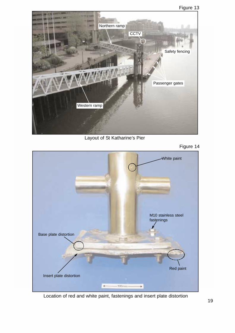
Two ramps provide access to the pier. The western ramp is the normalpassenger access and this is locked at about 2100, after the last routine riverservice call. The northern ramp is normally locked because of the acute angle itassumes at low tide and the risk this poses to passenger safety. The layout ofthe pier is shown at Figure 13.
1.9.3 CCTV
A CCTV camera is situated on the top of the pier centre support pillar. Thecamera is controlled and the images recorded by the security department of thenearby International House building on St Katharine’s Way. The St Katharine’sDock harbourmaster cannot monitor the camera images.
At the time of the accident, the camera was pointing towards St Katharine’sDock. It was not until 1307 that the security department in the InternationalHouse building was alerted to the accident. The camera was then redirected atSt Katharine’s Pier.
A further CCTV is fitted on the centre span of Tower Bridge, but this cannot scanSt Katharine’s Pier.
1.10 DESCRIPTION OF FAILED MOORING BOLLARD
1.10.1 General observations
The stainless steel mooring bollard was recovered by the Metropolitan Policeand was still connected to the 6mm aluminium insert plate by 6 x M10 stainlesssteel bolts and associated washers, nuts and lock nuts. The arrangement hadbeen repaired, and the weld securing the insert plate to the supporting structurehad failed. Weld material with signs of porosity was found on the edges of theinsert plate.
There was also considerable distortion of the bollard stainless steel base plateand aluminium insert plate. The latter had suffered the greatest deformation.There did not appear to be any damage to the bolts, bollard, vertical andhorizontal pins, or associated pin fillet welds. However, all but one of thewashers had suffered severe deformation.
Also evident were areas of white paint at the upper part of the vertical pin, andan area of red paint on one corner of the insert plate (Figure 14).
1.10.2 Dimensional information
The combined weight of the bollard, insert plate and fixtures was recorded as14.169kg. The vertical pin is 76.1mm in diameter and 200mm high. Thehorizontal pins are 44.4mm in diameter and are positioned 130mm up from thebase plate.
18
19
Layout of St Katharine’s Pier
Figure 13
Western ramp
Passenger gates
Safety fencing
CCTV
Northern ramp
Location of red and white paint, fastenings and insert plate distortion
Figure 14
White paint
Insert plate distortion
M10 stainless steelfastenings
Red paint
Base plate distortion
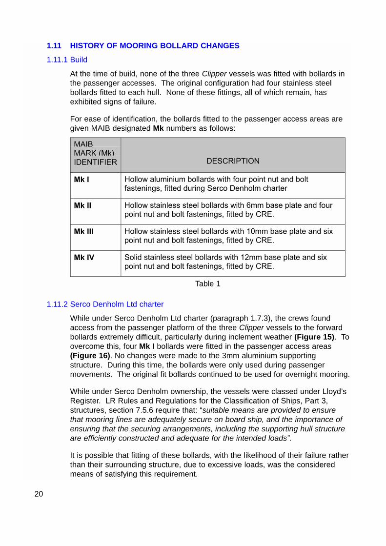
1.11 HISTORY OF MOORING BOLLARD CHANGES
1.11.1 Build
At the time of build, none of the three Clipper vessels was fitted with bollards inthe passenger accesses. The original configuration had four stainless steelbollards fitted to each hull. None of these fittings, all of which remain, hasexhibited signs of failure.
For ease of identification, the bollards fitted to the passenger access areas aregiven MAIB designated Mk numbers as follows:
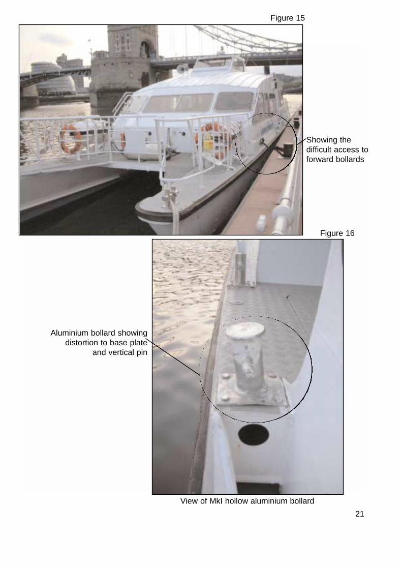
1.11.2 Serco Denholm Ltd charter
While under Serco Denholm Ltd charter (paragraph 1.7.3), the crews foundaccess from the passenger platform of the three Clipper vessels to the forwardbollards extremely difficult, particularly during inclement weather (Figure 15). Toovercome this, four Mk I bollards were fitted in the passenger access areas(Figure 16). No changes were made to the 3mm aluminium supportingstructure. During this time, the bollards were only used during passengermovements. The original fit bollards continued to be used for overnight mooring.
While under Serco Denholm ownership, the vessels were classed under Lloyd’sRegister. LR Rules and Regulations for the Classification of Ships, Part 3,structures, section 7.5.6 require that: “suitable means are provided to ensurethat mooring lines are adequately secure on board ship, and the importance ofensuring that the securing arrangements, including the supporting hull structureare efficiently constructed and adequate for the intended loads”.
It is possible that fitting of these bollards, with the likelihood of their failure ratherthan their surrounding structure, due to excessive loads, was the consideredmeans of satisfying this requirement.
20
MAIBMARK (Mk)IDENTIFIER DESCRIPTION
Mk I Hollow aluminium bollards with four point nut and boltfastenings, fitted during Serco Denholm charter
Mk II Hollow stainless steel bollards with 6mm base plate and fourpoint nut and bolt fastenings, fitted by CRE.
Mk III Hollow stainless steel bollards with 10mm base plate and sixpoint nut and bolt fastenings, fitted by CRE.
Mk IV Solid stainless steel bollards with 12mm base plate and sixpoint nut and bolt fastenings, fitted by CRE.
Table 1
21
Showing thedifficult access toforward bollards
Figure 15
Aluminium bollard showingdistortion to base plate
and vertical pin
Figure 16
View of MkI hollow aluminium bollard

Very few of the engineers who were involved with the vessels, still work forSerco Denholm Ltd. However, Serco Denholm’s technical staff confirmed thatthe bollards were designed to crumple under stress loading to protect thepassenger platform, although no drawings or calculations could be located tosupport this.
Lloyd’s Register has no records of the changes made to the bollard arrangementand they were not consulted regarding their suitability to withstand the ‘inservice’ loads.
1.11.3 CRE ownership
On taking ownership of Sky Clipper, CRE replaced the Mk I aluminium bollardsfitted to the passenger access areas, some of which had already failed (Figure17). Two Mk II bollards were fitted to the after end of the access as it was foundthat the forward two were not required for the River Thames operation.However, within 6 weeks of service, the weld at the base of the bollards’ verticalpin began to fracture and the base plates deformed. The bollard design wassubsequently changed, and the defective bollards were replaced with Mk IIIbollards. The increase in base plate thickness resolved the base platedistortion, but the bollard vertical pin still suffered deformation.
22
Failed MkI bollard
Figure 17

When CRE took delivery of Star Clipper, the vessel was still fitted with four Mk Ibollards. Between October 2003 and January 2004, when the vessel was firstin service, the port forward bollard was damaged while alongside at anovernight mooring. Some time between December 2003 and January 2004, thetwo after Mk I bollards were replaced with Mk IV bollards. The two forwardbollards, which included the damaged one, were left in place.
1.12 OWNERS’ RESPONSIBILITY TO REPORT DEFECTS/FAILURES
The responsibility for owners of vessels certified by the MCA to report failuresand changes to structure and equipment, is stipulated in the following:
• Statutory Instrument 2000 No 1334, paragraph 8 (1) (b) and (c) which states:
Responsibilities of owner and master
(b) after any survey of the ship required by these Regulations has beencompleted, no change shall be made in the structural arrangements, machinery,equipment and other items covered by the survey, without the approval of theappropriate Certifying Authority, except by direct replacement and
(c) whenever an accident occurs to a ship or a defect is discovered, either ofwhich affects the safety of the ship or the efficiency or completeness of its life-saving appliance or other equipment:
(i) it is reported at the earliest opportunity to the appropriate Certifying Authority ……..
• Notes affixed to the Passenger Certificate and Safety Management Certificate dated 18 February 2004 (Annex B).
1.13 BOLLARD REPAIRS FOLLOWING FAILURE ON 9 APRIL 2004
1.13.1 Background
On 9 April 2004, the port after Mk IV type bollard in Star Clipper’s passengeraccess was torn from the deck. Whilst leaving a pier, the eye of the mooringrope caught on both the pier bollard and the vessel’s bollard. As the vesselwent astern, force was exerted onto the after face of the vessel’s bollard, tearingup three sides of the supporting 3mm aluminium deck checker plate (Figure18).
CRE commissioned Alweld, of Rainham in Kent, a company well known tothem, to conduct the repair. Alweld had, over a three year period, completed awide range of work on the ‘Clipper’ vessels to the satisfaction of CRE, includingthe fabrication of the Mk II, Mk III and Mk IV bollards. Alweld was consideredby CRE to be intimately acquainted with the three ‘Clipper’ vessels andcompetent to conduct routine repairs.
23
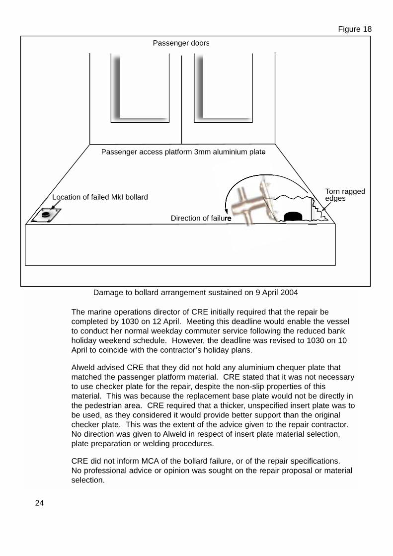
The marine operations director of CRE initially required that the repair becompleted by 1030 on 12 April. Meeting this deadline would enable the vesselto conduct her normal weekday commuter service following the reduced bankholiday weekend schedule. However, the deadline was revised to 1030 on 10April to coincide with the contractor’s holiday plans.
Alweld advised CRE that they did not hold any aluminium chequer plate thatmatched the passenger platform material. CRE stated that it was not necessaryto use checker plate for the repair, despite the non-slip properties of thismaterial. This was because the replacement base plate would not be directly inthe pedestrian area. CRE required that a thicker, unspecified insert plate was tobe used, as they considered it would provide better support than the originalchecker plate. This was the extent of the advice given to the repair contractor.No direction was given to Alweld in respect of insert plate material selection,plate preparation or welding procedures.
CRE did not inform MCA of the bollard failure, or of the repair specifications. No professional advice or opinion was sought on the repair proposal or materialselection.
24
Passenger doors
Passenger access platform 3mm aluminium plate
Location of failed MkI bollardTorn raggededgesedges
Direction of failur
Figure 18
Damage to bollard arrangement sustained on 9 April 2004
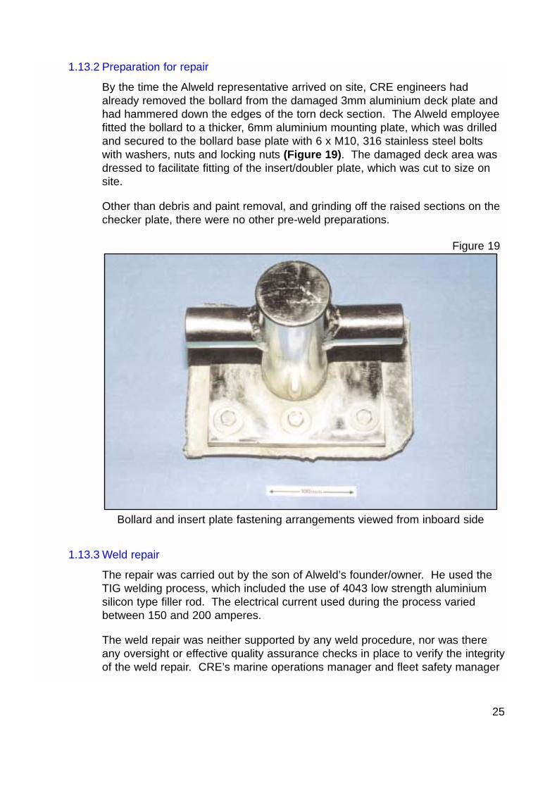
1.13.2 Preparation for repair
By the time the Alweld representative arrived on site, CRE engineers hadalready removed the bollard from the damaged 3mm aluminium deck plate andhad hammered down the edges of the torn deck section. The Alweld employeefitted the bollard to a thicker, 6mm aluminium mounting plate, which was drilledand secured to the bollard base plate with 6 x M10, 316 stainless steel boltswith washers, nuts and locking nuts (Figure 19). The damaged deck area wasdressed to facilitate fitting of the insert/doubler plate, which was cut to size onsite.
Other than debris and paint removal, and grinding off the raised sections on thechecker plate, there were no other pre-weld preparations.
1.13.3 Weld repair
The repair was carried out by the son of Alweld’s founder/owner. He used theTIG welding process, which included the use of 4043 low strength aluminiumsilicon type filler rod. The electrical current used during the process variedbetween 150 and 200 amperes.
The weld repair was neither supported by any weld procedure, nor was thereany oversight or effective quality assurance checks in place to verify the integrityof the weld repair. CRE’s marine operations manager and fleet safety manager
25
Bollard and insert plate fastening arrangements viewed from inboard side
Figure 19
visually checked the repair on 10 April. They stated that they were inexperiencedin welding techniques, but thought it to be a satisfactory repair. This belief wasbased on the amount of weld material evident.
The owner of Alweld visually examined the weld on 13 April, while the vesselwas in service. He raised no concerns about the quality of the repair.
1.14 ALWELD - FABRICATION AND WELDING COMPANY
1.14.1 Background
Alweld was established in 2001 and are advertised as welding and fabricationspecialists. The owner had previously been employed as a welder/fabricatormanager for the London Underground Jubilee Line Extension. He stated he hadheld a Lloyd’s Register welding qualification, but this had lapsed about 10 yearsbefore the accident.
The company employees comprise the founder/owner, who has 30 yearsexperience in the welding and general fabrication field; his son, a welder andgeneral fabricator; and the owner’s wife who acts in an administrative role. Thecompany occasionally sub contracts some work out.
1.14.2 Welder’s experience
The owner’s son conducted the repair. He had 2½ years’ experience in weldingstainless steel, mild steel and aluminium. He has also undertaken some generalfabrication work. His experience has been gained from a combination of “on thejob training” conducted by his father, and self-tuition. He had no formal weldingtraining and held no welding qualifications.
Prior to starting the repair, the welder sought advice, by telephone, from hisfather who was on holiday in France. He outlined his intentions for the repairand these were agreed with his father.
1.15 STAR CLIPPER’S PASSENGER ACCESS PLATFORM
1.15.1 Structure
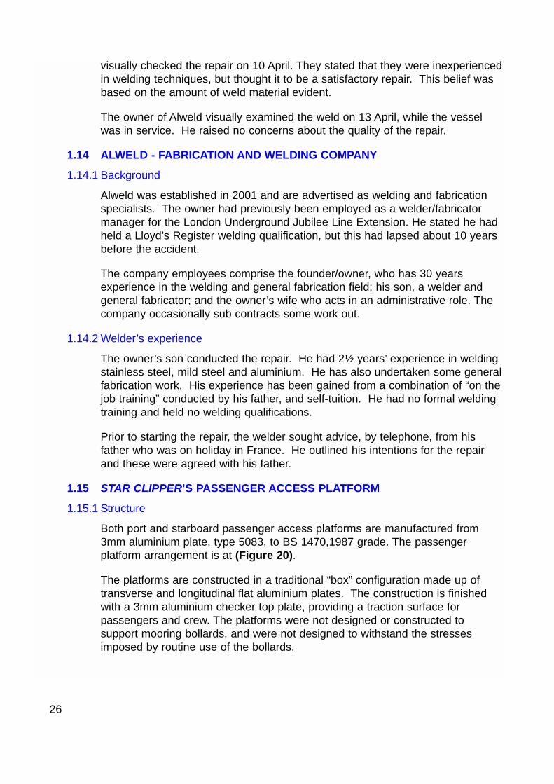
Both port and starboard passenger access platforms are manufactured from3mm aluminium plate, type 5083, to BS 1470,1987 grade. The passengerplatform arrangement is at (Figure 20).
The platforms are constructed in a traditional “box” configuration made up oftransverse and longitudinal flat aluminium plates. The construction is finishedwith a 3mm aluminium checker top plate, providing a traction surface forpassengers and crew. The platforms were not designed or constructed tosupport mooring bollards, and were not designed to withstand the stressesimposed by routine use of the bollards.
26
1.15.2 Bollard mounting area damage
Initial examination of the damaged structure confirmed the insert plate fillet weldhad failed. Much of the fillet weld was still in evidence, both on the verticalstructure and on the checker plate. There was no evidence of insert plateparent material remaining. It was noted that the aluminium checker platesupported the forward end of the insert plate. This effectively formed a doublerplate arrangement at this interface.
The 3mm aluminium under floor supporting structure had also suffered severedeformation.
1.16 MOORING ROPE
According to BS EN 699:1995, the mooring rope is defined as a 3-strandhawser laid polypropylene rope. The rope had a single eye, it was 24mm indiameter and 6.5m long, with a stated minimum breaking force of 79.65kN.During tensile testing, it was found that the rope’s actual breaking force was65.04kN.
CRE received the rope on 16 March 2004. It is not known when it was firstused. At the time of the accident, the rope was defect free, with the exceptionof some minor mooring-related abrasions to the inner face of the eye.
27
Passenger access platform - structural arrangement
Figure 20
Weld material
Checker platetraction surface
Structure acting asa doubler plate
Areas of platform deformation
1.17 INDEPENDENT REPORTS
The preliminary findings of the MAIB investigation indicated there was a need forspecialist assistance to determine the cause of the bollard failure, and toascertain how the bollard was catapulted clear of the pier river side safety fenceand struck the casualty.
The MAIB commissioned tests and examinations of:
• The bollard, bollard insert plate, weld and support structure.
• The polypropylene mooring rope and related possible bollard trajectories.
• Paint sample deposits on the bollard, insert plate and from the accident site.
1.17.1 Bollard, bollard insert plate, weld and support structure
The Test House (Cambridge) conducted a detailed analysis of the bollard insertplate welding and supporting structure. The report concluded that the failureoccurred through shear stress overloading of the recently completed insert platefillet weld.
Relevant extracts of the report are included at Annex C.
1.17.2 Polypropylene mooring rope and related possible bollard trajectories
Tension Technology International Ltd :
• Established load elongation characteristics of the mooring rope.
• Developed the three most likely scenarios for the bollard trajectory.
No significant defects were identified with the rope. The breaking strength of the rope was found to be 65.04kN corresponding to an elongation of 14.97%.
Throughout the various trajectory calculations it is likely that the vessel’s speed was not less than 0.55km/hr (0.3 knots) and not more than 2.32km/hr (1.3 knots).
Relevant extracts of the report are included at Annex D.
1.17.3 Paint sample deposits on the bollard, insert plate and from the accident site
The Test House (Cambridge) conducted comparison tests on paint samples fromthe bollard, insert plate and from the accident site in an attempt to ascertain thebollard trajectory. The results were inconclusive.
28
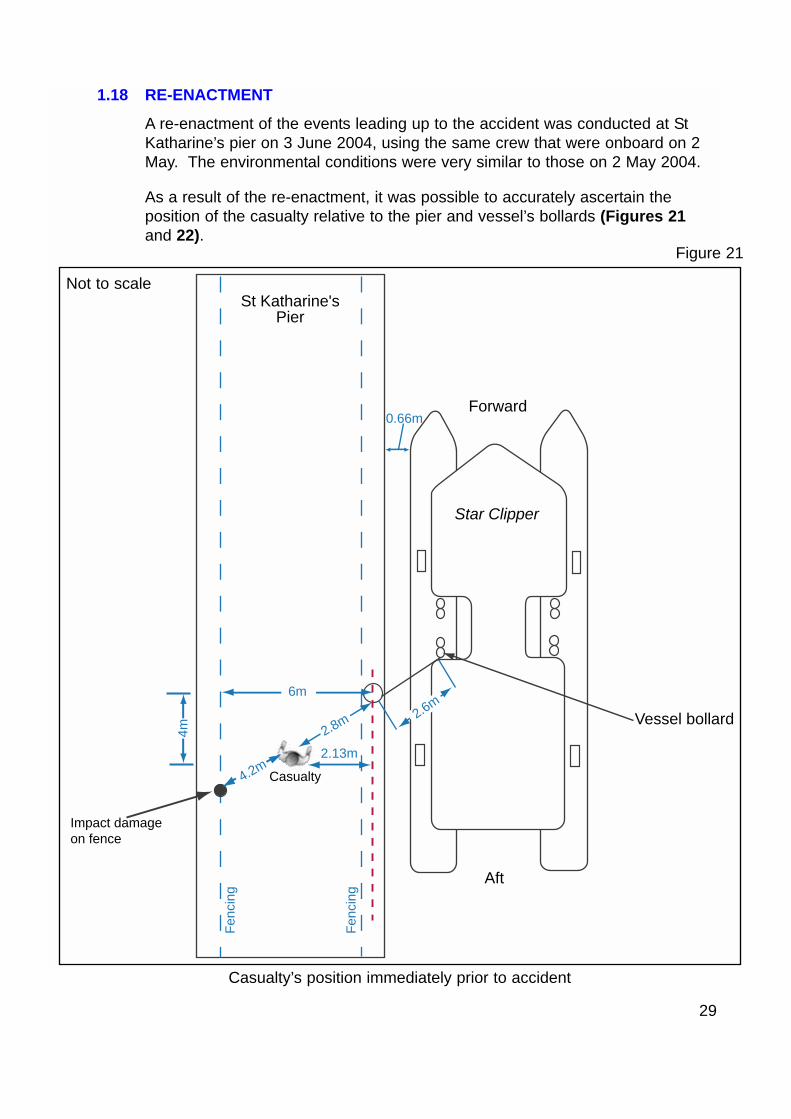
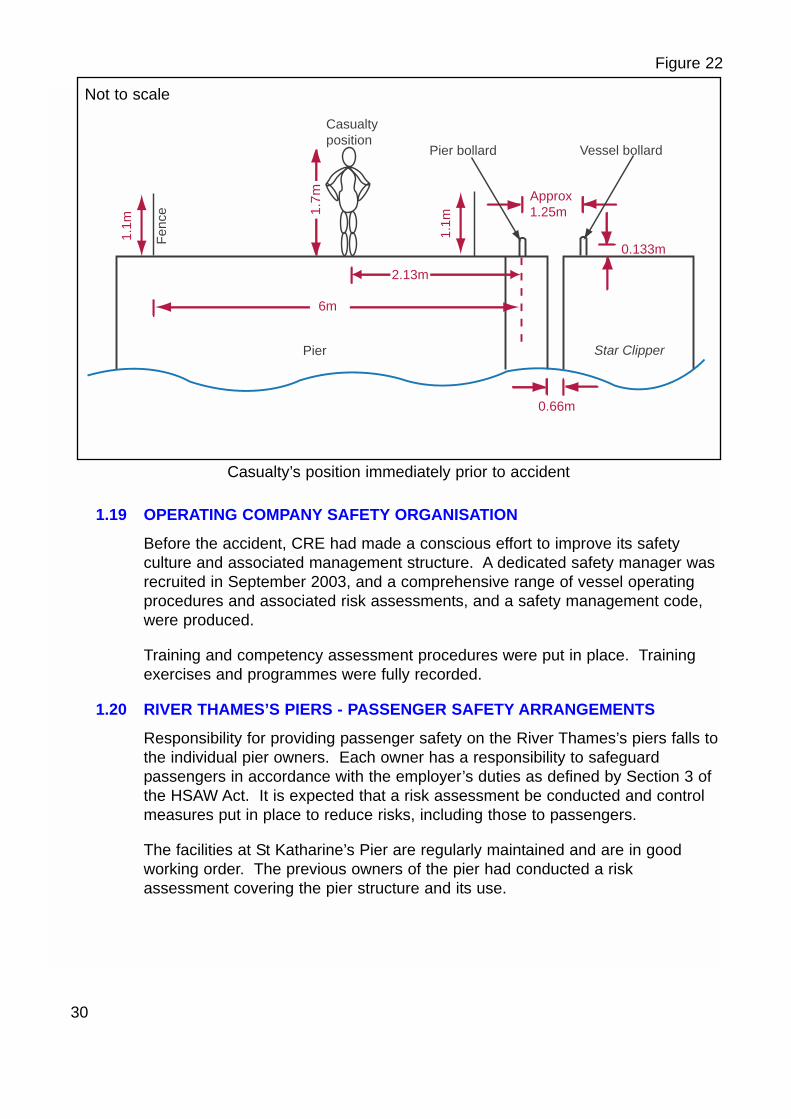
1.18 RE-ENACTMENT
A re-enactment of the events leading up to the accident was conducted at StKatharine’s pier on 3 June 2004, using the same crew that were onboard on 2May. The environmental conditions were very similar to those on 2 May 2004.
As a result of the re-enactment, it was possible to accurately ascertain theposition of the casualty relative to the pier and vessel’s bollards (Figures 21and 22).
29
Casualty’s position immediately prior to accident
Figure 21
St Katharine's Pier
4m
Fenc
ing
Fenc
ing
Forward
Aft
Star Clipper
2.13m
4.2m
Impact damageon fence
Casualty
6m
2.8m 2.6mVessel bollard
0.66m
Not to scale
1.19 OPERATING COMPANY SAFETY ORGANISATION
Before the accident, CRE had made a conscious effort to improve its safetyculture and associated management structure. A dedicated safety manager wasrecruited in September 2003, and a comprehensive range of vessel operatingprocedures and associated risk assessments, and a safety management code,were produced.
Training and competency assessment procedures were put in place. Trainingexercises and programmes were fully recorded.
1.20 RIVER THAMES’S PIERS - PASSENGER SAFETY ARRANGEMENTS
Responsibility for providing passenger safety on the River Thames’s piers falls tothe individual pier owners. Each owner has a responsibility to safeguardpassengers in accordance with the employer’s duties as defined by Section 3 ofthe HSAW Act. It is expected that a risk assessment be conducted and controlmeasures put in place to reduce risks, including those to passengers.
The facilities at St Katharine’s Pier are regularly maintained and are in goodworking order. The previous owners of the pier had conducted a riskassessment covering the pier structure and its use.
30
Casualty’s position immediately prior to accident
Figure 22
1.7m
1.1m
6m
Star Clipper
0.133m
Approx1.25m
0.66m
Fenc
e
Casualtyposition
Pier bollard Vessel bollard
Pier
2.13m
1.1m
Not to scale
SECTION 2 - ANALYSIS
2.1 AIM
The purpose of the analysis is to determine the contributory causes andcircumstances of the accident as a basis for making recommendations toprevent similar accidents occurring in the future.
2.2 BOLLARD REPLACEMENT
The original bollards required the crew to access the narrow walkway adjacentto the passenger cabin. There are no guardrails in this area, and no room to fitthem without impeding access. Using these bollards routinely could beextremely dangerous, especially during poor weather or during icy conditions.Merchant Shipping Notice No M718, issued in 1975, advises shipbuilders toensure that mooring arrangements are fit for the purpose of the intended vesseloperation. Siting the additional two mooring bollards in the passenger accessareas provided the crew with a greater degree of safety than using the originalfit bollards.
There had been a number of previous unreported bollard failures, but reasonsfor the failures had not been identified. It was reasonable for CRE to assumethat the Mk I bollards, fitted by Serco Denholm, were installed to an approvedstandard. However, CRE’s response of increasing the size of bollard materialsto overcome the problems they subsequently experienced, was inappropriate,and they should have sought expert advice.
2.3 REPORTING OF DEFECTS
The requirement for the owner to report defects affecting safety or efficiency ofthe vessel is laid down in statute (Paragraph 1.12). The conditions for the issueof the Passenger Certificate also reinforce the requirement to report defects(Annex B). The failure of the passenger platform structure on 9 April 2004 hada possible impact on the structural integrity of the hull. The validity of thePassenger Certificate could therefore have been in doubt. However, the ownerdecided not to report the fault to the Certifying Authority. In his view, thesubsequent modification utilising increased plate dimensions was sound, and fitfor purpose and ship’s safety was not compromised.
Owners are sometimes unclear about how to report defects, and are reluctant toreport those which, in their opinion, will not necessarily jeopardise a vessel’ssafety. Guidance to owners needs to be reinforced, to ensure there is noambiguity when reporting defects.
31
2.4 MCA INSPECTION AND SURVEY
The onus to report defects, and structural and equipment changes, rests with theowner, but the MCA also has the opportunity to identify areas of concern duringperiodic surveys and inspections.
The MCA’s “Instructions for the Guidance of Surveyors, Passenger ShipConstruction Classes III – VI (A) is clear. Annex E paragraph 13.1.1 requiresthat surveyors are satisfied that principal structure scantlings are maintained.Although the instruction does not explicitly mention bollard arrangements, theydo advise that “the ship is, in all respects, fit for the service intended”. Anopportunity was therefore lost for timely identification of the emerging defectsfollowing survey.
This investigation found that the bollard arrangement was not properly attachedto the ship’s structure to ensure a firm foundation for the dissipation of thebollard’s load. Because the bollard was not properly supported, unacceptableload was imposed on the passenger platform, which was itself attached to thehull structure via the hull cross beams.
There was evidence of a damaged Mk I bollard onboard at the time of thesurvey in February 2004. The survey could have prompted an inspection of thebollard and its supporting structure. If this had been done, the inspection couldhave revealed the inadequacy of the arrangement for the service intended.
2.5 SUITABILITY OF THE BOLLARD SUPPORTING STRUCTURE
The failure of the 3mm aluminium passenger access platform deck on 9 Aprilresulted in the mooring bollard being partially torn from the deck.
The weak point in the mooring arrangement should have been the mooring rope,which should have parted prior to the structure giving way. As this was not thecase, there was an opportunity for CRE to examine the cause of failure in moredetail. They could have sought professional advice on whether the bollardsupporting arrangements were sufficient for the likely mooring loads.
2.6 WELD REPAIR FAILURE AND INSERT PLATE MATERIAL SELECTION
Correct material selection and repair procedures are a fundamental part ofensuring a vessel meets the stringent certification requirements. Only bydefining these is it possible to confidently ensure that passenger and crew safetyis not compromised.
There was no agreed repair specification and only superficial repair qualityassurance measures were taken following the bollard failure on 9 April. Thesewere cursory visual examinations of the finished weld and bollard platefastenings by inexperienced CRE employees. They were inadequate for thissafety critical load bearing arrangement.
32
2.6.1 Material selection
Insufficient consideration was given by both CRE and Alweld to the importanceof correct material selection for the bollard insert plate. No professional advicewas sought. The only consideration given was that the plate was large enoughto cover the damaged deck area and accommodate the bollard, and that it wassubstantially thicker than the original material. The aluminium used for the insertwas an “off cut”. No thought was given as to whether it would be suitable forthe likely operational requirements.
2.6.2 Weld repair considerations
The initial damage to the checker plate, and stretching of the securing boltholes, was an opportunity to alert the welder/fabricator to the lack of structuralstrength in the passenger access area. He did not raise any concerns withCRE, perhaps because of his lack of experience.
CRE, recognising that they did not have the experience to advise on thetechnical details of the repair, left the engineering decisions to the young welder.The only stated requirement was that the insert plate was to be of thickermaterial. Merchant Shipping Notice M718 (Annex F) emphasises the need toensure that weld repairs to mooring, towing and hauling equipment are carriedout by a fully competent welder. Based on the results of previous Alweldwelding and fabrication work on Thames Clipper vessels, CRE believed thatAlweld were competent, and therefore satisfied the requirements of M718.
The welder did seek advice and approval from his father, who was in France onholiday at the time. However, approving the repair process, without having seenthe failed item and the scope of work, could have easily led to amisunderstanding regarding the complexity of the repair.
2.6.3 Shear forces required for failure
The independent report on the bollard failure indicated that if all of the insertplate weld failed simultaneously, the shear force required to achieve this wouldbe in the region of 321.9kN. This is far in excess of the rope’s actual breakingforce of 65.04kN. Therefore, if this was the mode of failure, the rope wouldhave parted before the bollard failed. This was not the case, therefore, theforces required for the weld to fail must have been below 65.04kN.
Visual examination of the deformation of the insert plate, indicate failure throughprogressive tearing. This appears to have initiated at the inboard edge andpropagated around the weld, bending the corners as it did so, before beingcatapulted into the waiting passengers. The independent report suggests that arelatively low shear force of 47.1kN, equating to a vessel speed of between 0.3and 1.3 knots, is required to achieve this, a force well within the rope’s breakingforce.
33
What is less clear is whether the initial propagation occurred at the time ofmooring at St Katharine’s Pier on 2 May 2004. While the mate did not noticeany defects with the repair arrangements, it is probable that initial propagationoccurred some time between the completion of the repair on 12 April and 2May. During this period, there were approximately 1200 moorings. Each mighthave contributed to the insert plate deformation.
2.7 VESSEL OPERATION
2.7.1 Approach to St Katharine’s Pier
CRE does not have any specific instructions for its captains, on procedures forcoming alongside piers. Owing to the constantly changing conditions on theriver, it would be unreasonable to provide such instructions, other than on how tomoor the vessel. Star Clipper’s captain was an experienced, fully licensedWaterman. He had undergone a period of training and assessment for hissuitability for the role and could competently assess the appropriate approachprocedure to suit the circumstances. There is no concern regarding his vesselhandling ability, or that of his crew.
The captain’s final procedure for coming alongside St Katharine’s Pier, on 2 May2004, was consistent with that expected by the company’s fleet operationsmanager, who conducts the competency assessments.
However, before berthing Star Clipper at St Katharine’s Pier he did overtakeSarpedon, which was exiting the northern bankside arch of Tower Bridge.Sarpedon was making 3 - 4 knots onto the pier, which is only 100m from TowerBridge. Clearly, Star Clipper must have been making in excess of 4 knots toenable her to reach the berth before Sarpedon.
Some witnesses, including the casualty’s husband, have commented that thevessel approached the pier at speed. A number have also said that theapproach was normal and safe, including the captain of Sarpedon, anexperienced licensed Waterman, who was immediately astern of Star Clipper.None of these statements can be verified by supporting evidence such as CCTVfootage. However, the vessel is extremely manoeuvrable and was perfectlycapable of approaching the pier at a safe speed after overtaking Sarpedon.
2.7.2 Coming alongside
The process of mooring a vessel has the potential to impose large stresses onher mooring equipment. It is important that the captain’s intentions areunambiguous and understood by the crew so that potentially dangeroussituations are prevented from developing.
34

Star Clipper’s captain was conscious that Sarpedon also wished to comealongside the pier. He decided that it would be helpful to move towards theeastern end of the pier, astern of Sarah Kathleen, rather than go to the usualposition on the pier. Unfortunately, he did not inform the mate of his intentionsprior to coming alongside. As far as the mate was concerned, the vessel wasgoing to her normal mid-gate position. The passengers heard the captain say“we will go to the next gate”, by which time the mate had already passed a ropeashore and put a running turn around the vessel’s bollard. There is no evidenceto suggest that anything other than minimal power was applied to move thevessel ahead.
The mate reported that, at the time of the bollard failure, Star Clipper wasslightly less than 1m from the pier, and that the captain was using minimalahead way to bring Star Clipper alongside. He, and the waiting passengers,noticed that the pier was “bouncing” from the wash effect from a number ofsmall vessels in the vicinity. This surface disturbance would have added to thestresses on the mooring bollard.
When the insert plate weld failed, Star Clipper did not surge up the pier, so thepropulsion thrust at this point must have been minimal. Witnesses, who werestanding in the passenger cabin at the time, stated they felt no suddenmovement, and none was noticed by those passengers standing on the pier.This further supports the view that the applied power was minimal.
2.7.3 Mooring procedures
The routine of using the eye of the mooring rope to capture the pier bollard, andthen securing the loose end to the vessel’s bollard, prevents the need for themate to jump ashore, thus avoiding the risk of injury. Securing the mooring rope(“fetching up”) prior to the vessel coming alongside, enables the captain to usethe rope as a “spring”. This speeds up the mooring process, but in turn putsconsiderable stress onto the bollards and rope. The stress is exacerbated bythe pier’s “bouncing” motion, which also “snatches” at the rope.
Stresses imposed on the mooring bollards could be reduced if, once the eye ofthe rope has been passed onto the shore bollard, a running turn is made aroundthe ship’s bollard instead of “fetching up” the rope. This would allow the amountof weight coming onto the rope and bollard to be controlled by slacking the ropedown as required. Once the rope has been passed around the vessel’s bollard,the captain could manoeuvre into position alongside the pier, using the rudderand water jets controls. Once the vessel is in position the mooring rope couldthen be made fast.
35
2.8 BOLLARD TRAJECTORY
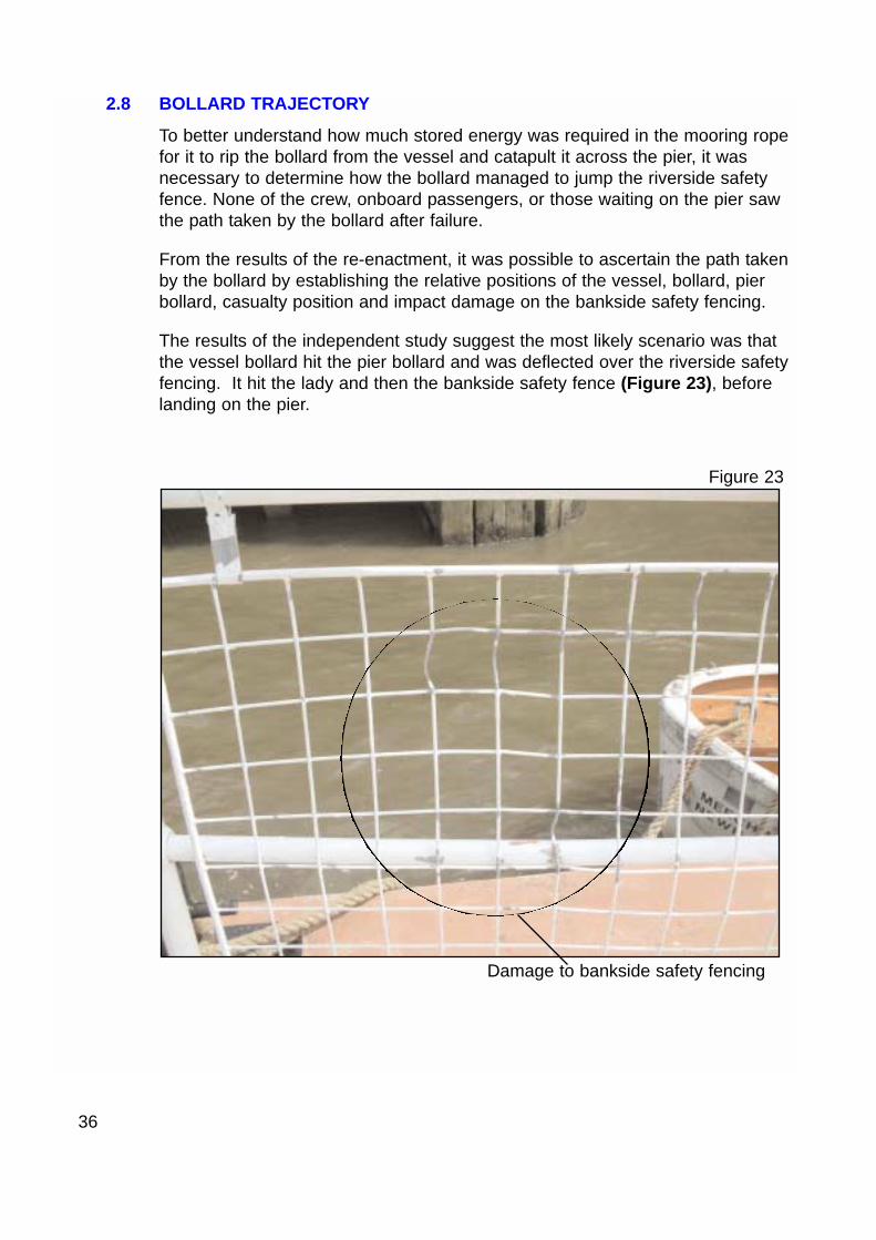
To better understand how much stored energy was required in the mooring ropefor it to rip the bollard from the vessel and catapult it across the pier, it wasnecessary to determine how the bollard managed to jump the riverside safetyfence. None of the crew, onboard passengers, or those waiting on the pier sawthe path taken by the bollard after failure.
From the results of the re-enactment, it was possible to ascertain the path takenby the bollard by establishing the relative positions of the vessel, bollard, pierbollard, casualty position and impact damage on the bankside safety fencing.
The results of the independent study suggest the most likely scenario was thatthe vessel bollard hit the pier bollard and was deflected over the riverside safetyfencing. It hit the lady and then the bankside safety fence (Figure 23), beforelanding on the pier.
36
Damage to bankside safety fencing
Figure 23
2.9 ROPE SELECTION
When the safety manager joined CRE in September 2003, he recommendedthat the company use nylon ropes, instead of polypropylene ropes, because ofthe nylon ropes’ ability to absorb greater shock loads. Hence their suitability tocope with “snatching” and wash-related stresses during mooring. Thisrecommendation was not made on the basis that he was aware of bollardfailures, but was based on his previous marine experience.
Following this initiative, mooring trials were conducted using nylon ropes duringnormal commuter services. It was reported that the crews disliked using them,mainly because of the greater stretch properties and weight of nylon comparedwith polypropylene. Polypropylene ropes are also easier to splice than nylonropes, and they tend to be stiffer, and are therefore easier to handle and throwover the bollards.
On some occasions when nylon ropes were used it was found that when theystretched, the vessel moved up the pier away from the open passenger gates,thus impeding the access by passengers, and risking their safety. In commonwith the majority of River Thames users, CRE has reverted to usingpolypropylene ropes.
2.10 PIER SAFETY
The facilities at St Katharine’s Pier are well maintained and the pier isconsidered fit for purpose.
There is no suggestion that the pier arrangements contributed in any way to theaccident. However, St Katharine’s Dock harbourmaster, stated that the riskassessment associated with pier operations was in need of updating, havingbeen completed during the previous owner’s tenure.
It is important for owners of River Thames piers to keep their operations underreview to reflect changing requirements and to ensure pier safety.
2.11 FATIGUE
The crew of Star Clipper were all well rested prior to assuming their dutiesbetween 0900 and 1000 on 2 May 2004. They had completed only one roundtrip before the accident. Fatigue is not considered a factor in this accident.
2.12 PLA AND RNLI REACTIONS
Both the crews of the PLA harbour launch Westbourne and Tower lifeboatresponded extremely quickly to the request for assistance. Both teams werefaced with the very difficult situation of a casualty in deep trauma and a numberof waiting passengers suffering from shock. They conducted themselves in acalm and thoroughly professional manner throughout the accident.
37
SECTION 3 - CONCLUSIONS
3.1 SAFETY ISSUES
The following safety issues have been identified by the investigation. They arenot listed in any order of priority:
1. The passenger access platform structure was inadequate to support the bollardstresses imposed during normal mooring operations. [2.3, 2.5]
2. The original build, forward bollards are unsuitable for routine commuter servicemooring requirements. The access to the bollards is hazardous and there areno guardrails. [2.2]
3. The cause of earlier bollard failures was not sufficiently investigated to checksuitability of the structure or of the impact of mooring operations. [2.2 ]
4. CRE did not inform MCA of the replacement of the bollards or the subsequentfailure on 9 April 2004. [2.3]
5. There were no weld specification or adequate quality assurance measures inplace for the bollard repair following the failure on 9 April 2004. [2.6]
6. During the MCA inspection and survey on 2 and 18 February 2004, no bollarddefects were recorded. [2.4]
7. MCA’s Guidance of Surveyors does not explicitly cover mooring arrangements.[2.4]
8. Insufficient consideration was given to the importance of correct materialselection for the bollard insert plate. [2.6.1]
9. The weld repair and 6mm aluminium insert/doubler lacked the necessarystrength to ensure that the bollard could accept normal mooring loads. [2.6.3]
10. The mooring rope was secured to both the pier and vessel before it wasalongside, causing stresses to be built up in the rope and bollard structure.[2.7.3]
38
SECTION 4 - ACTION TAKEN
4.1 MARITIME AND COASTGUARD AGENCY
The MCA published a “Safety Alert” Marine Information Note, MIN176 (M+F), inMay 2004, titled “Mooring Cleat Failures”. The publication highlighted the needto regularly examine mooring equipment fastenings, and provide advice onberthing aimed at reducing loading on mooring equipment. A copy of the SafetyAlert is at Annex G.
On 10 May 2004, the MCA (South East District) required owners and operatorsof all Class V vessels operating on the River Thames to check all bollards anddeck connections. Positive reporting was required within 7 days of theinstruction. A copy of the instruction is at Annex H.
4.2 PORT OF LONDON AUTHORITY
The PLA issued an instruction on 13 May 2004 to the owners and operators ofall PLA licensed passenger vessels (carrying 12 passengers and under) tocheck the integrity of mooring arrangements. A copy of the instruction is atAnnex I.
This instruction has been amended to include inspection of mooring equipmentand associated fittings on all types of commercial vessels on the PLA shippingregister.
4.3 COLLINS RIVER ENTERPRISES
On 3 May 2004, CRE conducted a risk assessment and issued an operatingprocedure to cover “Mooring arrangements for the embarkation anddisembarkation of passengers”. A copy of the risk assessment and operatingprocedure is at Annex J.
CRE has conducted evaluation of the mooring rope loadings, to determine thebollard supporting structure design. The design has been approved by theMCA.
4.4 ST KATHARINE’S DOCK HARBOURMASTER
The St Katharine’s Dock harbourmaster has reviewed and updated the riskassessment relating to the operation of St Katharine’s Pier.
39
SECTION 5 - RECOMMENDATIONS
The Maritime and Coastguard Agency is recommended to:
2005/112 Review the Guidance of Surveyors, Passenger Ship Construction ClassesIII – VI (A) and associated surveyor’s aides memoire to include therequirement to conduct an external visual inspection of any bollards andmooring equipment that are fitted.
2005/113 Revise and re-issue the instructions under MSN No M.718 covering theimportance of the need for careful weld preparation, correct materialselection and the use of fully qualified and competent welders whenundertaking repairs to mooring, towing and hauling equipment.
2005/114 Promulgate additional guidance to owners on the requirement to reportdetails of proposed mooring fitting modifications, general defects andchanges in a vessel’s use to the Certifying Authority for approval inaccordance with statutory requirements and conditions attached to thePassenger Certificate and Domestic Safety Management Certificate.
Collins River Enterprises are recommended to:
2005/115 Take into account, where appropriate, the need to seek expert advice ontechnical matters. In particular, where structural repairs or modificationsare proposed to ensure that materials are correctly selected, and repairsfollow approved procedures and standards to cope with expected “inservice” loads.
Marine Accident Investigation BranchFebruary 2005
40