Embed Size (px)
Citation preview

ANSI/SSFI SC100-5/05
American National Standard
STANDARDS FOR TESTING AND RATING SCAFFOLD ASSEMBLIES AND COMPONENTS
Scaffolding, Shoring & Forming Institute, Inc. Sponsor: Scaffolding, Shoring & Forming Institute, Inc. 1300 Sumner Ave Cleveland, Ohio 44115-2851

ANSI/SSFI SC100-5/05
i
SCAFFOLDING, SHORING & FORMING INSTITUTE AMERICAN NATIONAL STANDARD
Standards for Testing and Rating Scaffold Assemblies and Components
Sponsor Scaffolding, Shoring & Forming Institute, Inc.

ANSI/SSFI SC100-5/05
ii
A Scaffolding, Shoring & Forming Institute (SSFI) standard or recommended procedure is intended as a guide to aid the manufacturer, the consumer, and the general public. The existence of an SSFI standard or recommended procedure does not in any respect preclude anyone, whether he has approved the standard or recommended procedure or not, from manufacturing, marketing, purchasing or using products, processes, or procedures not conforming to the standard or recommended procedure. Scaffolding, Shoring & Forming Institute standards and recommended procedures are subject to periodic review and users are cautioned to obtain the latest editions. NOTICE: Scaffolding, Shoring & Forming Institute standards and procedures may be revised or withdrawn at any time. The procedures of the SSFI require that action be taken to reaffirm, revise, or withdraw standards and recommended procedures no later than five years from the date of publication. Purchasers of Scaffolding, Shoring & Forming Institute standards and procedures may receive current information on all documents by calling or writing the Scaffolding, Shoring & Forming Institute. Sponsored and published by: SCAFFOLDING, SHORING & FORMING INSTITUTE 1300 Sumner Avenue Cleveland, OH 44115-2851 Phn: 216/241-7333 Fax: 216/241-0105 E-Mail: [email protected] URL: www.ssfi.org Copyright © 2002 by Scaffolding, Shoring & Forming Institute, Inc. All Rights Reserved No part of this publication may be reproduced in any form, in an electronic retrieval system or otherwise, without the prior written permission of the publisher. Suggestions for improvement of this standard will be welcome. They should be sent to the Scaffolding, Shoring & Forming Institute, Inc. Printed in the United States of America
Scaffolding, Shoring &
Forming Institute

ANSI/SSFI SC100-5/05
iii
CONTENTS PAGE Foreword ..........................................................................................................................................iv 1. Introduction ..................................................................................................................................1 2. Scope ...........................................................................................................................................1 3. Definitions .....................................................................................................................................1-4 4. General Test Requirements ...........................................................................................................5-6 5. Test Procedures .............................................................................................................................6-15
5.1 Methods for Testing and Rating Tube and Coupler Scaffold Components ..........................6-8 5.2 Methods for Testing and Rating Welded Frame Scaffold Assemblies .................................9 5.3 Methods for Testing and Rating System Scaffold Assemblies .............................................10-11 5.4 Methods for Testing and Rating Guardrail Scaffold Components........................................11 5.5 Methods for Testing and Rating Screwjack Scaffold Components ......................................12 5.6 Methods for Testing and Rating Caster Scaffold Components.............................................12-13 5.7 Methods for Testing and Rating Putlog Scaffold Assemblies ..............................................14 5.8 Methods for Testing and Rating Side and End Bracket Scaffold Components ....................15
Appendices Appendix A Tube & Coupler Scaffold Component Test Report Form ............................................16-17 Appendix B Welded Frame Scaffold Assembly Test Report Form, Series A – B ...........................18-19 Appendix C System Scaffold Assembly Test Report Form, Series A – C .......................................20-22 Appendix D Guardrail Scaffold Component Test Report Form .......................................................23 Appendix E Screwjack Scaffold Component Test Report Form ......................................................24 Appendix F Caster Scaffold Component Test Report Form.............................................................25-26 Appendix G Putlog Scaffold Assembly Test Report Form...............................................................27 Appendix H Side and End Bracket Scaffold Component Test Report Form....................................28 Figures Figures 5.1A – 5.1D ...........................................................................................................................29-31 Figures 5.2A – 5.2B ...........................................................................................................................32-33 Figures 5.3A – 5.3C............................................................................................................................34-36 Figures 5.4A – 5.4C............................................................................................................................37 Figure 5.5A.........................................................................................................................................38 Figures 5.6A – 5.6G ...........................................................................................................................39-40 Figure 5.7A.........................................................................................................................................41 Figure 5.8A – 5.8B .............................................................................................................................41-42

ANSI/SSFI SC100-5/05
iv
Foreword (This foreword is included for information only and is not part of SSFI SC100 Standard for Testing and Rating Scaffold Assemblies and Components.) This SSFI standard was developed by the Scaffolding Section and the Scaffold Standards Committee of the Scaffolding, Shoring & Forming Institute, Inc. as an assistance and guide to the manufacturers, purchasers, and users of scaffolding. It provides methods for testing and rating scaffold assemblies and components. The methods in this standard are intended to provide a means of comparison only. Due to the wide variety of situation specific factors involved in the use of scaffolds, it is not possible to develop a method that will apply to all possible situations while still providing useful information upon which comparisons can be made. The ratings derived from the methods in this standard apply to the specific conditions contained in the test procedures. The ratings are not intended to represent actual use conditions, but, rather, they are intended to provide a reference point at which a comparison can be made. Users, purchasers, specifiers, and other interested parties should contact the manufacturer for ratings of specific configurations. SSFI employed the canvass method to demonstrate consensus and to gain approval as an American National Standard. The ANSI Board of Standards Review granted approval as an American National Standard on May 24, 2005. SSFI recognizes the need to periodically review and update this standard. All questions or suggestions for improvement should be forwarded to the Scaffolding, Shoring & Forming Institute, Inc., 1300 Sumner Avenue, Cleveland, Ohio, 44115-2851. All constructive suggestions for expansion and revision of this standard are welcome. The existence of a Scaffolding, Shoring & Forming Institute (SSFI) standard or recommended procedure does not in any respect preclude any member or non-member from manufacturing or selling products not conforming to the standard or recommended procedure and the SSFI is not responsible for the use of the standard or recommended procedure. At the time this standard was developed, the following were members of the SSFI Scaffold Section:
A-1 Plank & Scaffold Manufacturing Inc. 500 Commerce Parkway Hays, KS 67601
Patent Construction Systems/SGB U.S.A. One Mack Centre Drive Paramus, NJ 07652
Action Scaffold Manufacturing P. O. Box 20492 Phoenix, AZ 85036
Perry Manufacturing, Inc. 1233 W. 18th St. Indianapolis, IN 46202
Aluma Enterprises Inc. 1111 North Loop West, Suite #700 Houston, TX 77008
Safway Services Inc. N19 W24200 Riverwood Drive, Waukesha, WI 53188
bil-jax, inc. 125 Taylor Parkway Archbold, OH 43502
Universal Manufacturing Corp. 550 West New Castle Street Zelienople, PA 16063
Layher Inc. 7151 Fir Tree Drive Mississauga, Ontario Canada L5S 1G4
WACO Scaffolding & Equipment 4545 Spring Road P. O. Box 318028 Cleveland, OH 44131

ANSI/SSFI SC100-5/05
1
Standards for Testing and Rating Scaffold Assemblies and Components 1 Introduction This standard contains procedures for testing and rating scaffold components and assemblies. These procedures are intended to be used as a guide for industry testing practice and are not intended to supersede procedures set forth in any applicable Federal, State, or local regulations. The Institute believes that adherence to these procedures will yield reliable test results upon which comparisons can be made. It takes no responsibility for such results. The methods in this standard are intended to provide a means of comparison only. Due to the wide variety of situation specific factors involved in the use of scaffolds, it is not possible to develop a method that will apply to all possible situations while still providing useful information upon which comparisons can be made. The ratings derived from the methods in this standard apply to the specific conditions contained in the test procedures. The ratings are not intended to represent actual use conditions, but, rather, they are intended to provide a reference point at which a comparison can be made. Users, purchasers, specifiers, and other interested parties should contact the manufacturer for ratings of specific configurations. Normal shop safety practice and, when applicable, safety precautions described by OSHA, should be observed during the administration of these tests. 2 Scope This standard provides methods for testing and rating the performance of the following:
! Tube and Coupler Scaffold Components ! Welded Frame Scaffold Assemblies ! System Scaffold Assemblies ! Guardrail Scaffold Components ! Screwjack Scaffold Components ! Caster (with Lever Actuated Brake and Swivel Lead) Scaffold Components ! Putlog Scaffold Assemblies ! Side and End Bracket Scaffold Components
3 Definitions 3.1 Accessories – Those items other than frames, braces, post shores, end frame access ladders and horizontal
locking trusses used to facilitate the construction of scaffolds. 3.2 Adjustment Screw – See Screwjack 3.3 Allowable Load or Rated Load* – The ultimate load or the slip load divided by a factor of safety. 3.4 Base Plate – A device used to distribute the vertical load. 3.5 Bay – The space between two adjacent posts along the face of a system scaffold. 3.6 Caster Capacity – The maximum recommended load per caster or wheel. Capacity is based on intermittent duty
over smooth surfaces at speeds not exceeding 3 m.p.h., no shock loads or adverse environment conditions. 3.7 Caster – A pivoting wheel, containing a wheel lock and a swivel lock which is attached to the base of a scaffold
tower for manual movement of the scaffold.
* These terms may be used synonymously.

ANSI/SSFI SC100-5/05
2
3.8 Caster Size – A method of classifying casters based on the nominal diameter of the wheel. 3.9 Castor – See Caster. 3.10 Coupler Or Clamp* – A device for locking together the component parts of a tubular metal scaffold. 3.11 Coupler, Right Angle – Also known as a clamp - A device used to fasten scaffold tubes or pipes together at right
angles. 3.12 Coupler, Swivel - Also known as an adjustable coupler or clamp - A device used to fasten scaffold bracing
members together at angles other than right angles. 3.13 Coupling Pin Or Sprocket* – An insert device used to connect lifts, tiers, or posts vertically
3.14 Cross Bracing – A system of members which connect frames or panels of scaffolding laterally to make a tower
or continuous structure. 3.15 Diagonals – Fixed length members sized to fit with the appropriate horizontal members of the scaffold.
3.16 End Bracket – See Side Bracket. 3.17 End Connector – A device attached to the ends of scaffold tubing (pipe) used to fasten the tubes together end for
end. 3.18 Extension Device – Any device, other than an adjustment screw, used to obtain vertical adjustment of
scaffolding equipment. 3.19 Factor of Safety – The ratio of ultimate load to the allowable load. In the case of coupler slippage, the ratio of
the slip load to the allowable load. 3.20 Flat Top – A level mounting surface above the bearing plate of the caster. 3.21 Frame or Panel* – The principal prefabricated, welded structural unit in a tower.
3.22 Guardrail – A rail system erected along the open sides and ends of platforms. The rail system consists of a
toprail and midrail and their supports. 3.23 Horizontals – Fixed length members with a fitting built into each end for attaching to posts at locking cups or
rings. Used as bearers, runners and guardrails. 3.24 Horn – The part of the caster that comprises legs plus the horn base of a swivel caster or the mounting plate of a
rigid caster.
3.25 Independent Testing Laboratory – An organization or company which is not affiliated with a scaffold manufacturer and which conducts tests of scaffold assemblies and components. An Independent Testing Laboratory shall be designated as a Nationally Recognized Testing Laboratory (NRTL), or shall be accredited by the American Association for Laboratory Accreditation (A2LA), or shall be accredited by the National Voluntary Laboratory Accreditation Program (NVLAP), or shall be accredited or certified by an equivalent nationally or internationally recognized association or agency.
3.26 King Pin – A rivet, stem stud or bolt with nut used to hold the mounting plate and horn assembly of a swivel
caster together. * These terms may be used synonymously.

ANSI/SSFI SC100-5/05
3
3.27 Leg – Vertical load bearing component of frame or panel (see also, post). 3.28 Lifts Or Tiers* – In welded frame scaffolds, the number of frames erected one above another in a vertical
direction. In other scaffolds, the assembly of bearers and runners forming each horizontal level of a scaffold. 3.29 Live Load – The total weight of workers, equipment and other loads that will exist and move about on a
scaffold. 3.30 Load Bearing Member – Any component of a scaffold which is directly subjected to load. 3.31 Locking Device – A device used to secure the cross brace to the frame or panel. 3.32 Mounting Plate – The flat base, usually with 4 mounting holes, that forms the top of the caster. This permits
attachment by bolting or welding to the scaffold. 3.33 Mudsill − See Sill. 3.34 Offset – The distance from the center of the kingpin to the center of the axle. Also called the swivel lead. 3.35 Overall Height (caster) – The distance from the rolling surface to the top of the mounting plate. 3.36 Panel − See Frame or End Frame Access Ladder 3.37 Post or Standard – The vertical component of a system scaffold, with locking cups or rings located at fixed
height increments for attaching horizontal bearers, runners, diagonals and accessories. 3.38 Putlog (truss) – Horizontal load bearing component consisting of upper and lower chords supporting web
members.
3.39 Qualified Engineer – An engineer who, by possession of a recognized degree, certificate, or professional standing, and who by extensive knowledge, training, and experience, has successfully demonstrated the ability to solve or resolve problems relating to scaffolds, scaffold assemblies, and scaffold components.
3.40 Rated Load (See Allowable Load).
3.41 Safe Leg Load – The load that can be directly imposed, safely, on a scaffold post or leg. (See Allowable Load) 3.42 Scaffold – Any temporary elevated platform (supported or suspended) and its supporting structure (including
points of anchorage), used for supporting employees or materials or both.
3.43 Scaffold Layout – A design diagram for scaffolding.
3.44 Screwjack – A leveling device or jack composed of a threaded screw and an adjusting handle used for the vertical adjustment of scaffolding.
3.45 Shock Load – Impact of material as it is released or dumped during placement. 3.46 Shore Heads – Flat or formed metal pieces which are placed and centered on vertical members. * These terms may be used synonymously.

ANSI/SSFI SC100-5/05
4
3.47 Side Bracket – A cantilevered component attached to a leg or post to extend the platform. 3.48 Sill or Mud Sill* – A footing (usually wood) which distributes the vertical loads to the ground or slab below. 3.49 Span – The horizontal distance between posts, columns, or upright support members. 3.50 Standard – See Post. 3.51 Static Load – The load imposed upon a caster when it is stationary. 3.52 Stem – A vertical round bar on top of the mounting plate that may be inserted into a scaffold leg. 3.53 Swivel Brake – A device that clamps onto the mounting plate, brake plate, or mounting plate assembly to
prevent the caster from turning. 3.54 Swivel Lead − See Offset. 3.55 Testing Apparatus or Fixture – A special purpose device fabricated for the express purpose of testing scaffolding
and scaffolding components. 3.56 Testing Machine – A device or apparatus used to apply a variable load to a component or assemblage of
components. Often found in universities, colleges and reputable testing laboratories. 3.57 Tower – A composite structure of posts, horizontals and diagonals, or in welded frame scaffolds, a composite
structure of frames and cross bracing.
3.58 Truss – See Putlog
3.59 Tube And Coupler Equipment - An assembly used as a load-carrying structure consisting of tubing or pipe which serves as posts, braces, and ties, a base supporting the posts, and special couplers which serve to connect the uprights and join the various members.
3.60 Ultimate Load – The maximum load which may be applied to a component or structure just prior to failure. In
the case of coupler slippage, the load required to move the coupler 1/4 of an inch along a tube.
3.61 Wheel Brake – A device which prevents movement of the caster by clamping on to the wheel. 3.62 Yoke – See Horn.
* These terms may be used synonymously.

ANSI/SSFI SC100-5/05
5
4 General Test Requirements 4.1 Calibration of Testing Devices
4.1.1 Devices used to determine loads applied shall be calibrated and certified by a reputable testing laboratory during the preceding 12 month period.
4.1.2 Testing machines used for compression testing shall be calibrated in accordance with ASTM E4-99 Standard
Practices for Force Verification of Testing Machines or latest revision or an equivalent standard during the preceding 12 month period.
4.1.3 Testing machines used for calibration in Part 4.1.1 and 4.1.2 above shall be calibrated in accordance with
ASTM E74-95 Standard Practice for Calibration of Force-Measuring Instruments for Verifying the Force Indication of Testing Machines or latest revision or an equivalent standard during the preceding 12 month period.
4.2 Test Procedures Testing shall be according to the following procedures or an equivalent internationally
recognized testing standard that meets or exceeds the SSFI criteria outlined in the following procedures.
4.2.1 Test Specimens: Specimens to be tested shall be selected at random and shall exhibit approximately the same variations in measurements as would be expected from random sampling, including mill tolerances on thickness of various members. Note the test specimens should never be placed in service, regardless of their condition after the test. The application of the test load has, by definition, “failed” the specimen.
4.2.2 Sample Size: For each individual loading condition, the minimum number of tests shall be carried out on each piece of equipment or accessory as follows: for metal equipment or accessories, a minimum of three tests shall be performed; for wooden equipment or accessories, a minimum of ten tests shall be performed.
4.2.3 Average of Test Results: The average of the valid test set shall be used to determine ratings as stated in 4.5. The valid test set shall comprise the following: 4.2.3.1 For metal equipment and accessories, if three successive tests result in a maximum variation between the
average of the three tests and each individual test result of 10%, the three tests shall be the valid test set.
4.2.3.2 For metal equipment and accessories, if three successive tests result in a maximum variation between the average of the three tests and each individual test greater than 10% but less than or equal to 15%, conduct a fourth test. If the four successive tests result in a maximum variation between the average of the four tests and each individual test result of 15%, the four tests shall be the valid test set.
4.2.3.3 For metal equipment and accessories, four tests out of a set of 5 tests as follows: 4.2.3.3.1 Conduct four tests. If the maximum variation between the average of the four tests and three
individual test results is 15%, with variation between the fourth individual test and the average being greater than 15%, a fifth test shall be performed.
4.2.3.3.2 Determine the average of the three test results identified in 4.4.3.1 (those within the maximum 15% variation) and the fifth test. If the maximum variation between this average and each individual test result is 15%, the three tests identified in 4.4.3.1 and the fifth test shall be the valid test set.
4.2.3.3.3 If the maximum variation between the average determined in 4.4.3.2 and any individual test result is greater than 15%, another complete set of four tests shall be run and all nine tests shall be considered the valid test set.

ANSI/SSFI SC100-5/05
6
4.2.3.4 For wood equipment and accessories, ten successive tests if the maximum variation between the average of the ten tests and each individual test result is 30%.
4.2.3.5 For wood equipment and accessories, 20 tests if the maximum variation between the average of the first ten successive tests and each individual test result is greater than 30%.
4.3 Determination of Rating: With the exception of Guardrail Scaffold Components, the average obtained as specified in 4.4 shall be divided by the appropriate factor of safety to determine ratings. The determination of Guardrail Scaffold Component ratings are included in Section 5.4 of this standard.
4.4 Published Ratings: All published ratings and load charts prepared by utilizing this standard shall reference this standard and, where applicable, shall clearly indicate the type of test conducted to determine the ratings.
4.5 Measurements: Thickness measurements, when required, shall be made with a suitable micrometer. All other dimensions shall be made with a commercially obtainable measuring tape. All dimensions shall be reported to the nearest 1/16 inch.
4.6 Certification of Tests: All tests shall be witnessed by a qualified engineer or independent testing laboratory which shall be designated as a Nationally Recognized Testing Laboratory (NRTL), or shall be accredited by the American Association for Laboratory Accreditation (A2LA), or shall be accredited by the National Voluntary Laboratory Accreditation Program (NVLAP), or shall be accredited or certified by an equivalent nationally or internationally recognized association or agency. The qualified engineer or a representative of the independent testing laboratory shall certify that the tests were performed in accordance with applicable provisions of this standard and that recorded results are factual.
5 Test Procedures 5.1 Methods for Testing and Rating Tube and Coupler Scaffold Components 5.1.1 Scope: These procedures are intended to cover:
A. The compression, tension and buckling testing of tube (pipe) end connectors when assembled into the ends of scaffold tube (pipe).
B. The strength and slip capacity of both right angle and swivel couplers. C. Torque capacity of coupler bolt assembly (where applicable).
5.1.2 Test Apparatus: The following apparatus shall be used to conduct tests of end connectors and right angle and
swivel couplers
5.1.2.1 End Connector Test − A device constructed to apply both a tension or compression load to a tube (pipe) end connector as shown in figure 5.1A.
5.1.2.2 Right Angle and Swivel Coupler Test − A device constructed to apply a slip load as shown in figure 5.1B or
a strength test load as shown in figure 5.1C. 5.1.3 Methods for Testing and Rating Tube (Pipe) End Connectors
5.1.3.1 Tension Test
5.1.3.1.1 Using randomly selected production tubes or pipes with end connectors installed, assemble two
sections as they would be assembled during a scaffold erection. Install the assemblies into a testing machine or apparatus.

ANSI/SSFI SC100-5/05
7
5.1.3.1.2 Apply a tension load to the assembly (refer to figure 5.1A). Load shall be applied in 1,000 lb.
increments. Load shall be allowed to stabilize until measuring device shows no movement after 1 minute before the next load increment is applied.
5.1.3.1.3 The ultimate tensile load is achieved when the following occurs:
a. Joint failure occurs; or b. The end connector slips a maximum of 1/4 inch from the tube end; or c. The tube ends separate 1/4” from each other, dependent on type of end-to-end connector
being used.
5.1.3.2 Compression Test 5.1.3.2.1 Apply a compression load to a separate assembly (refer to figure 5.1A). 5.1.3.2.2 Load shall be applied in 1,000 lb. increments. Load shall be allowed to stabilize until measuring
device shows no movement after 1 minute before the next load increment is applied. 5.1.3.2.3 The ultimate compression load is reached when:
a. The tube (pipe) splits or bends; or b. The joint assembly will no longer support the test load; or c. The tube ends separate 1/4” from each other, in the case of a parallel connector.
5.1.3.3 Buckling Test
5.1.3.3.1 Install end connectors on 3 foot 3 inch sections of tube (pipe), connect tubes (pipes) together and
install in a test apparatus. 5.1.3.3.2 Apply a compression load allowing end condition rotation as shown in figure 5.1A to assembly until
tube buckling failure. 5.1.3.3.3 Load shall be applied in 1,000 lb. increments. Load shall be allowed to stabilize until measuring
device shows no movement after 1 minute before the next load increment is applied. 5.1.3.3.4 After test, examine end connectors and attachments to tubes (pipes). Record the failure mode and
load at point of failure.
5.1.4 Methods for Testing and Rating Right Angle Couplers and Swivel Couplers: Using randomly selected production
couplers, install a coupler in test apparatus and test as follows:
5.1.4.1 Slip test 5.1.4.1.1 Fasten coupler around two, 1 foot min. long tubes (pipes) depending upon the coupler design.
Tighten coupler in accordance with manufacturer’s recommendations.
5.1.4.1.2 Install assembly in test apparatus and apply a load to the horizontal tube (pipe) in such a manner as to equally load the tube (pipe) on either side of the coupler (see figure 5.1B). Using a measuring device, monitor the coupler slip as load is applied.
5.1.4.1.3 Load shall be applied in steps of 500 lb. increments. Load shall be allowed to stabilize until measuring device shows no movement after 1 minute before the next load increment is applied. Couplers shall not be re-torqued during test.
ANSI/SSFI SC100-5/05
8
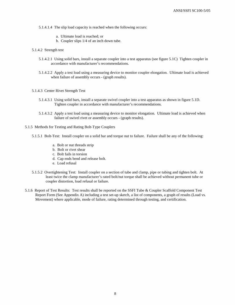
5.1.4.1.4 The slip load capacity is reached when the following occurs:
a. Ultimate load is reached; or b. Coupler slips 1/4 of an inch down tube.
5.1.4.2 Strength test
5.1.4.2.1 Using solid bars, install a separate coupler into a test apparatus (see figure 5.1C) Tighten coupler in
accordance with manufacturer’s recommendations.
5.1.4.2.2 Apply a test load using a measuring device to monitor coupler elongation. Ultimate load is achieved when failure of assembly occurs - (graph results).
5.1.4.3 Center Rivet Strength Test 5.1.4.3.1 Using solid bars, install a separate swivel coupler into a test apparatus as shown in figure 5.1D.
Tighten coupler in accordance with manufacturer’s recommendations. 5.1.4.3.2 Apply a test load using a measuring device to monitor elongation. Ultimate load is achieved when
failure of swivel rivet or assembly occurs - (graph results).
5.1.5 Methods for Testing and Rating Bolt-Type Couplers
5.1.5.1 Bolt-Test: Install coupler on a solid bar and torque nut to failure. Failure shall be any of the following:
a. Bolt or nut threads strip b. Bolt or rivet shear c. Bolt fails in torsion d. Cap ends bend and release bolt. e. Load refusal
5.1.5.2 Overtightening Test: Install coupler on a section of tube and clamp, pipe or tubing and tighten bolt. At
least twice the clamp manufacturer’s rated bolt/nut torque shall be achieved without permanent tube or coupler distortion, load refusal or failure.
5.1.6 Report of Test Results: Test results shall be reported on the SSFI Tube & Coupler Scaffold Component Test
Report Form (See Appendix A) including a test set-up sketch, a list of components, a graph of results (Load vs. Movement) where applicable, mode of failure, rating determined through testing, and certification.

ANSI/SSFI SC100-5/05
9
5.2 Methods for Testing and Rating Welded Frame Scaffold Assemblies 5.2.1 Scope: This procedure is intended to cover the compression testing of welded frame scaffold assemblies. 5.2.2 Test Setup: The welded frame scaffold tower to be tested shall be erected in such a manner as to simulate field
conditions and shall be aligned vertically so that it is not out of plumb more than 1/8" in three feet and no more than the diameter of the leg. No greater attempts should be made to adjust the components concentrically than would be expected in actual use.
5.2.3 Loads
5.2.3.1 The load shall be applied directly on the load bearing members by use of load transfer beams or cross head
of testing machine; or directly by hydraulic jacks in an appropriate testing apparatus or fixture.
5.2.3.2 The welded frame scaffold tower shall be subjected to increasing loads until the ultimate load is reached.
5.2.3.3 The allowable limits for rate of loading on welded frame scaffold towers shall not be less than 5,000 lbs. per minute nor more than 10,000 lbs. per minute.
5.2.3.4 The rate of loading in each test shall remain constant.
5.2.4 "A" Series Tests (Required)
5.2.4.1 Welded frame scaffold assemblies shall be tested one frame wide and one cross brace length long by three
frames high to arrive at an anticipated allowable leg load. The frame scaffold components shall be erected into the above configuration composed of four vertical legs with normal manufacturers' recommended bracing, freestanding, and with adjusting screws extended to 12 inches beyond the frame length on the bottom. (See figure 5.2A).
5.2.4.2 The four legs of the test configuration shall be loaded until the ultimate load of the legs (Pult) is reached.
Determine the allowable leg load (Pall) for this configuration (and for use in the “B” series tests, if desired) by dividing the ultimate leg load by the appropriate factor of safety.
5.2.5 "B" Series Tests (Optional)
5.2.5.1 After conducting "A" series tests, welded frame scaffold assemblies shall be tested one frame wide and two
cross brace lengths long by three frames high. The frame scaffold components shall be erected into the above configuration composed of six vertical legs with normal manufacturers' recommended bracing freestanding, and with adjusting screws extended to 12 inches beyond the frame length on the bottom. (See figure 5.2B).
5.2.5.2 The six legs of the test configuration are to be loaded to the scaffold's anticipated leg load (Pall), as determined by the "A" series test, and held at that value for one minute. Loading shall be continued on the two legs of the center frame until the ultimate load of these two legs is reached. The ultimate load of the center frame legs shall be the ultimate leg load for the welded frame system. Determine the allowable leg load for this configuration by dividing the ultimate leg load by the appropriate factor of safety.
5.2.6 Report of Test Results: Test results shall be reported on the SSFI Welded Frame Scaffold Assembly Test Report
Form (See Appendix B) including drawing of test setup and list of components with the following: ultimate total test load, ultimate leg load, type of test, mode of failure, rating determined through testing, and certification.

ANSI/SSFI SC100-5/05
10
5.3 Methods for Testing and Rating System Scaffold Assemblies 5.3.1 Scope: This procedure is intended to cover the compression testing of system scaffold assemblies. 5.3.2 Test apparatus: The system scaffold tower to be tested shall be erected in such a manner as to simulate field
conditions and aligned vertically so that it is not out of plumb more than 1/8" in three feet and no more than the diameter of the post. No greater attempts should be made to adjust the components concentrically than would be expected in actual use.
5.3.3 Loads
5.3.3.1 The load shall be applied directly on the load bearing members by use of load transfer beams or cross head
of testing machine; or directly by hydraulic jacks in an appropriate testing apparatus or fixture. 5.3.3.2 The system scaffold tower shall be subjected to increasing loads until the ultimate load is reached.
5.3.3.3 The allowable limits for rate of loading on system scaffold towers shall not be less than 5,000 lbs. per
minute nor more than 10,000 lbs. per minute.
5.3.3.4 The rate of loading in each test shall remain constant. 5.3.4 "A" Series Tests (Required)
5.3.4.1 Posts shall be tested one bay wide and one bay long, composed of 4 vertical posts, by three lifts high to
arrive at an anticipated allowable post load. The system scaffold components shall be erected freestanding in the above configuration with adjusting screws extended to 12 inches beyond the post on the bottom and with horizontals and diagonals installed as shown in figure 5.3A.
5.3.4.2 The four posts of the test configuration shall be loaded simultaneously until the ultimate load of the posts
(Pult) is reached. Determine the allowable post load (Pall) for this configuration (and for use in the “B” and “C” series tests) by dividing the ultimate post load by the appropriate factor of safety.
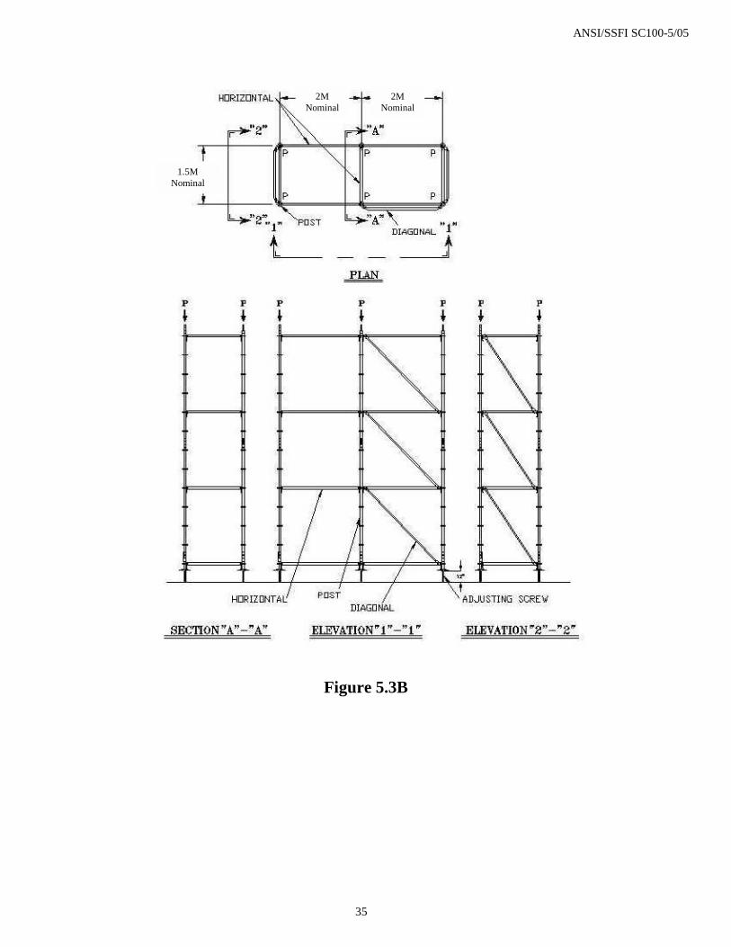
5.3.5 "B" Series Tests (Optional)
5.3.5.1 After conducting "A" series test, posts shall be tested one bay wide and two bays long, composed of 6 vertical posts, by three lifts high. The system scaffold components shall be erected in the above configuration with adjusting screws extended to 12 inches beyond the post on the bottom and with horizontals and diagonals installed as shown in figure 5.3B.
5.3.5.2 The six posts of the test configuration are to be loaded to the anticipated allowable post load (Pall), as determined in the "A" series test, and held at that value for one minute.
5.3.5.3 Loading shall be continued on the two posts in the center of the bays until the ultimate load of the posts is reached. The ultimate load of the center posts shall be the ultimate post load for the system scaffold used in this manner. Determine the allowable post load (Pall) for this configuration by dividing the ultimate post load by the appropriate factor of safety.
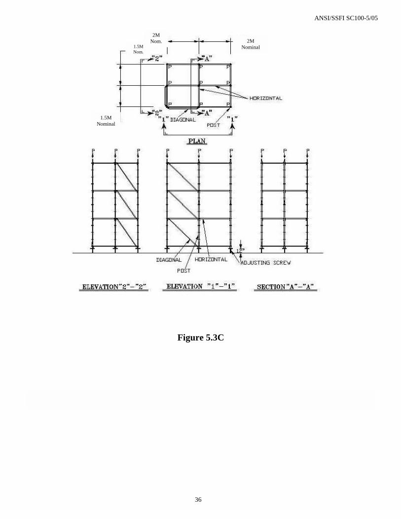
5.3.6 C" Series Tests (Optional)
5.3.6.1 After conducting "A" series test, posts shall be tested two bays wide and two bays long, composed of 9
vertical posts, by three lifts high. The system scaffold components shall be erected in the above configuration with adjusting screws extended to 12 inches beyond the post on the bottom and with horizontals and diagonals installed as shown in figure 5.3C.

ANSI/SSFI SC100-5/05
11
5.3.6.2 The nine posts of the test configuration are to be loaded to the anticipated allowable post load (Pall), as determined in the "A" series test, and held at that value for one minute.
5.3.6.3 Loading shall be continued on the post in the center of the bays until the ultimate load of the post is reached. The ultimate load of the center post shall be the ultimate post load for the system scaffold when used in this manner. Determine the allowable post load (Pall) for this configuration by dividing the ultimate post load by the appropriate factor of safety.
5.3.7 Report of Test Results: Test results shall be reported on the SSFI System Scaffold Assembly Test Report Form
(See Appendix C) including drawing of test setup and list of components with the following: ultimate total test load, ultimate post load or component test load as applicable, type of test, mode of failure, rating determined through testing, and certification.
5.4 Methods for Testing Guardrail Scaffold Components 5.4.1 Scope: This procedure is intended to cover the load testing of Guardrail Scaffold Components. Guardrail
Scaffold Components covered in this section include Guardrail Posts, Guardrails and intermediate level Guardrail Panels.
5.4.2 Test Setup:
5.4.2.1 Guardrail Post: Attach post to a socket secured to a test apparatus. The socket shall be of the same configuration and material as the standard attachment to a scaffold. Assembly shall be in accordance with manufacturer’s recommendation. Post may be tested in either a vertical or horizontal position. Load shall be applied to the uppermost node of the post. Apply load at a right angle to the post. A measuring device shall be firmly attached that allows measurement of movement of the top of the guardrail post from its original preloaded position. (See Figure 5.4A)
(Alternate method: Post may be tested attached to a scaffold setup either as a single post or the center post of a two bay setup. Scaffold shall be restrained from tipping. Assembly shall be in accordance with manufacturer’s recommendation.)
5.4.2.2 Guardrail: A scaffold structure or mock-up shall be erected that consists of the typical understructure
necessary to support a minimum of two guardrail posts on the outboard side of a scaffold bay(s) with a top rail and mid rail between each pair of posts. If an intermediate level guardrail panel is to be tested, it shall be attached directly to a scaffold structure. The scaffold shall be restrained from tipping during testing. Assembly shall be in accordance with manufacturer’s recommendation. Load shall be applied to the center point of the top rail. The device and apparatus used to apply the load shall be configured in such a manner that allows the load to be applied in an outward and inward direction at a right angle to the guardrail and in a downward (vertical) direction. A measuring device shall be firmly attached that allows measurement of movement of the guardrail from its original preloaded position. (See Figure 5.4B and 5.4C)
5.4.3 Test Procedure
5.4.3.1 Erect scaffold or test apparatus as described in 5.4.2.1 and 5.4.2.2. 5.4.3.2 Apply load at a rate not to exceed 50 lbs. per minute. 5.4.3.3 Measure the deviation from original preloaded position with each approximately 50-pound increment of
load applied. 5.4.3.4 Increase load until load refusal occurs.
5.4.4 Report of Test Results: Test results shall be reported on the SSFI Guardrail Scaffold Component Test Report
Form (see Appendix D) including drawing of test set-up, list of components, mode of failure, and certification.

ANSI/SSFI SC100-5/05
12
5.5 Methods for Testing and Rating Screwjack Scaffold Components
5.5.1 Scope: This procedure is intended to cover the compression testing of screwjacks. 5.5.2 Test Apparatus: A device constructed to apply a compression load to a screwjack shall be used to conduct tests. 5.5.3 Test Procedure
5.5.3.1 Using randomly selected production screwjacks, move the handle of the screwjack upward until it is placed at the manufacturer's maximum recommended extension, measured from the top of the base plate to the top of the nut, without removing it from the jack.
5.5.3.2 Place the screwjack in the test machine or apparatus. Position a thick-walled tube on top of the jack handle.
The inside diameter of the thick-walled tube shall be the same inside diameter of the scaffold leg that would be placed on the screwjack. (See figure 5.5A).
5.5.3.3 Apply a compressive load to the screwjack. The allowable limits for rate of loading on screwjacks shall not
be less than 5,000 lbs. per minute nor more than 10,000 lbs. per minute. 5.5.3.4 Increase load until the ultimate vertical load is achieved. Ultimate vertical load is achieved when the
following occurs:
a. The jack handle slips; or b. The jack bends or buckles; or c. Load refusal.
5.5.4 Report of Test Results: Test results shall be reported on the SSFI Screwjack Scaffold Component Test Report
Form (See Appendix E) including drawing of test setup list of components, mode of failure, rating determined through testing, and certification.
5.6 Methods for Testing and Rating Caster (with Lever Actuated Brakes and Swivel Lead) Scaffold Components 5.6.1 Scope: This procedure is intended to cover:
A. Radial torque testing of the caster stem/mounting plate. B. Torque test of the swivel brake. C. Torque test of the wheel brake. D. Vertical load test of the caster.
5.6.2 Test Apparatus: The following apparatus shall be used to conduct tests of caster scaffold components:
5.6.2.1 Radial Torque Test: A device constructed to measure the rotational force. (See figures 5.6A and 5.6B).
5.6.2.2 Swivel Brake Torque Test: A device constructed to measure the brake capacity to prevent caster swivel. (See figures 5.6C and 5.6D).
5.6.2.3 Wheel Brake Torque Test: A device constructed to measure the capacity of the brake to prevent wheel
rotation. (See figures 5.6E and 5.6F).
5.6.2.4 Vertical Load Test: A device used to measure the capacity of the caster to support a vertical load. (See figure 5.6G).

ANSI/SSFI SC100-5/05
13
5.6.3 Radial Torque Test Procedure: Using randomly selected production casters, install the caster into a testing
machine or apparatus and test as follows (note: not applicable to over center locking casters):
5.6.3.1 Place the caster in a device to secure the mounting plate and to prevent any movement in the testing apparatus.
5.6.3.2 Apply radial torque to the stem or top plate of the caster in a slow and steady manner so that torque can be
measured. Increase load until the ultimate load is reached. The ultimate load is achieved when the caster stem or top plate rotates on the mounting plate. (See figures 5.6A and 5.6B).
5.6.4 Swivel Brake Torque Test Procedure (note: not applicable to over center locking casters) : Using randomly
selected production casters, install the caster into a testing machine or apparatus and test as follows:
5.6.4.1 Mount the caster wheel in a fixed position in the test apparatus. Apply the brake until it is fully engaged.
5.6.4.2 Apply torque to the stem of the caster or the caster plate in a slow and steady manner so that torque can be measured. Increase load until the ultimate load is reached. The ultimate load is achieved when the caster stem or plate rotates. (See figures 5.6C and 5.6D).
5.6.4.3 Wheel Brake Torque Test: Using randomly selected production casters, install the caster into a testing
machine or apparatus and test as follows:
5.6.4.3.1 Place the caster wheel in a fixed position and apply the brake until it is fully engaged. Apply torque radial to the axle bolt in the clockwise direction.
5.6.4.3.2 Apply torque in a slow and steady manner so that torque can be measured. Increase load until the
ultimate load is reached. The ultimate load is achieved when the brake slips on the surface of the wheel. (See figures 5.6E and 5.6F).
5.6.4.3.3 Repeat procedure, applying torque radial to the axle bolt in a counterclockwise direction until
ultimate load is reached.
5.6.5 Vertical Load Test Procedure: Using randomly selected casters, install the caster into a testing machine or apparatus and test as follows:
5.6.5.1 With the caster inversely mounted with the kingpin inserted in a rigid support with a 5 degree angle
between the stem and the vertical plane, apply a load vertically to the caster wheel. Load shall be applied in increments of ¼ the manufacturer’s rated load. Load shall be allowed to stabilize until measuring device shows no movement after 1 minute before the next load increment is applied.
5.6.5.2 The caster shall be removed at the manufacturer’s rated load for a visual inspection. After the caster is
placed back into the test apparatus, load shall be increased in increments of ¼ the manufacturer’s rated load. The caster shall be removed and inspected at multiples of 2, 3, and 4 times the rated load.
5.6.5.3 Increase load until the ultimate load is reached. Ultimate load is reached when permanent deformation can be seen in the stem, body or wheel of the caster or it becomes functionally impaired. (See figure 5.6G).
5.6.6 Report of Test Results: Test results shall be reported on the SSFI Caster Scaffold Component Test Report Form
(See Appendix F) including drawing of test setup and list of components with the following: Ultimate Stem Radial Torque Load, Ultimate Swivel Brake Torque Load, Ultimate Wheel Brake Torque Load, Ultimate Vertical Load, Type of Test, mode of failure, rating determined through testing, and certification.

ANSI/SSFI SC100-5/05
14
5.7 Methods for Testing and Rating Putlog Scaffold Assemblies 5.7.1 Scope: This procedure is intended to cover distributed load testing for putlog scaffold assemblies. 5.7.2 Test Apparatus: Putlog assemblies shall be tested on a scaffold for which they were designed to be used, and in a
configuration for which they are designed to be used. 5.7.3 Loads
5.7.3.1 Loads shall be applied uniformly over the putlog scaffold assembly using a test machine with falsework designed to simulate uniform loading; or by application of load media. Load media shall be of a material that allows natural deflection of the putlog scaffold assembly.
5.7.3.2 The rate of loading, when using a test machine, shall not be greater than 1000 lbs. per minute. 5.7.3.3 When using load media, the load media shall be applied in layers with each new layer starting in the center
of the putlog scaffold assembly and working towards the ends in both directions.
5.7.3.4 The rate of loading in each test shall remain constant. 5.7.4 Procedure for test
5.7.4.1 Assemble the putlog assembly according to manufacturer’s recommendation, including any and all bracing. Towers shall be restrained against movement during loading. The test configuration shall be comprised of two scaffold towers as high as necessary to accommodate recommended bracing, and one bay long. The putlog assemblies will span the void between the two towers. Prepare detailed illustration(s) of the test configuration.
5.7.4.2 Measure the free span of the putlog (“X” in figure 5.7A). Record this value on the test report.
5.7.4.3 Measure the center deflection.
5.7.4.4
5.7.4.4 Weigh the platform materials. Record this value on the test report.
5.7.4.5 Place the platform uniformly along the putlog structure.
5.7.4.6 Begin loading the platform. If using a load media, the load media shall be applied in layers with each new
layer starting in the center of the platform and working towards the ends in both directions.
5.7.4.7 If using a test machine, deflection readings are to be recorded at 200 lb. increments with the load held at the reading level until the reading has stabilized for 1 minute. If using a load media, note the deflection value upon completion of each layer of load media.
5.7.4.8 Continue to load until load refusal occurs. Record the reading on the test machine or the weight of the load
media applied at the point of load refusal. 5.7.5 Report of Test Results: Test results shall be reported on the SSFI Putlog Scaffold Assembly Test Report Form
(See Appendix G) Include a sketch of the setup, a list of components, and specify the member that failed, the mode of failure, ultimate load, allowable load, rating determined through testing, and certification.

ANSI/SSFI SC100-5/05
15
5.8 Methods for Testing and Rating Side and End Bracket Scaffold Components 5.8.1 Scope: This procedure is intended to cover distributed load testing procedures for scaffold side and end brackets. 5.8.2 Test Apparatus: Side and end brackets shall be tested on a scaffold for which they were designed to be used, and
in a configuration for which they are designed to be used or on an equivalent test apparatus that allows simulation of actual loading conditions.
5.8.3 Procedure of Test
5.8.3.1 Assemble the bracket according the manufacturer’s recommendation. The test configuration shall be comprised of a one tier high scaffold, one bay long, counterweighted to avoid overturning or of apparatus to simulate actual load conditions. Prepare detailed illustration(s) of the test configuration.
5.8.3.2 Record on the test report the diameter of the tube on which the hanger of the bracket rests (See figures 5.8A
and 5.8B).
5.8.3.3 Measure the cantilever length of the bracket. (“X” in figures 5.8A and 5.8B). Measure the depth of the bracket (“Y” in figures 5.8A and 5.8B). Record these values on the test report.
5.8.3.4 Weigh the platform material, if used. Record this value on the test report.
5.8.3.5 Determine whether this is a test for a hooked platform or a simply supported platform, or a simulated
uniform load. Record the appropriate entry in the test report.
5.8.3.6 Place the platform uniformly along the bracket ledger if used.
5.8.3.7 Begin loading the platform with load media. Load media shall be a material that allows natural deflection of the platform. The load media shall be applied in layers with each new layer starting in the center of the platform and working towards the ends in both directions, or apply load with test apparatus to simulate uniform load
5.8.3.8 Continue to uniformly apply weight to the structure until load refusal occurs.
5.8.3.9 Determine the amount of load on the structure at the time of load refusal. Record that value in the test
report. 5.8.4 Report of Test Results: Test results shall be reported on the SSFI Side and End Bracket Scaffold Component Test
Report Form (See Appendix H) Include a sketch of the setup, a list of components, and specify the member that refuses the load, mode of failure, ultimate load, allowable load, rating determined through testing, and certification.

ANSI/SSFI SC100-5/05
16
Appendix A TUBE & COUPLER SCAFFOLD COMPONENT TEST REPORT FORM (Page 1 of 2)
Manufacturer: Model #/Product Identification: Test Date: Test #: Test Location: Factor of Safety (FS):
End Connector Test 1 Test 2 Test 3 Test 4 (if needed)
Test 5 (if needed) Average Maximum
Variation
Rating (Avg /
FS) Tensile Load Note Failure Mode (Use “Notes”, if needed) NA NA NA
Compression Load Note Failure Mode (Use “Notes” if needed) NA NA NA
Buckling Load Note Failure Mode (Use “Notes” if needed) NA NA NA
Right Angle Coupler Test 1 Test 2 Test 3 Test 4 (if needed)
Test 5 (if needed) Average Maximum
Variation
Rating (Avg /
FS) Slip Load Note Failure Mode (Use “Notes” if needed) NA NA NA
Tensile Load Note Failure Mode (Use “Notes” if needed) NA NA NA
Swivel Coupler Test 1 Test 2 Test 3 Test 4 (if needed)
Test 5 (if needed) Average Maximum
Variation
Rating (Avg /
FS) Slip Load Note Failure Mode (Use “Notes” for add’l space if needed)
NA NA NA
Center Rivet Load Note Failure Mode (Use “Notes” for add’l space, if needed)
NA NA NA
Bolt Type Coupler Test 1 Test 2 Test 3 Test 4 (if needed)
Test 5 (if needed) Average Maximum
Variation
Rating (Avg /
FS) Maximum Bolt Torque Note Failure Mode (Use “Notes” if needed) NA NA NA
Overtightening Test Enter Manufacturer’s Recommended Torque: _________________
Pass
Or
Fail
Pass
Or
Fail
Pass
Or
Fail
Pass
Or
Fail
Pass
Or
Fail
NA NA NA
COMPLETE and ATTACH PAGE 2

ANSI/SSFI SC100-5/05
17
Appendix A TUBE & COUPLER SCAFFOLD COMPONENT TEST REPORT FORM (Page 2 of 2)
Sketch: Attach Sketch of Test, Graphs (if applicable), and list of components Notes:________________________________________________________________________________________________________________________________________________________________________________________________________________________________________________________________________ Witnesses
Name Company Signature Title
Certification I certify that I am a qualified engineer or a representative of an independent testing laboratory as defined in the SC100 standard. I also certify that the above described tests were performed in accordance with the applicable provisions of the Methods for Testing and Rating Tube & Coupler Scaffold Components, as published by the Scaffolding, Shoring & Forming Institute in the SSFI SC100 standard, and that the stated results and values are accurate. (Name) (Signature) (Company) (Date) (Address/city/state/zip) (Phone) (e-mail)

ANSI/SSFI SC100-5/05
18
Appendix B WELDED FRAME SCAFFOLD ASSEMBLY TEST REPORT FORM, SERIES A
Manufacturer: Model #/Product Identification:
Test Date: Test #: Test Location: Factor of Safety (FS): Series A Readings
Leg 1 Load Leg 2 Load Leg 3 Load Leg 4 Load Total Ultimate Load
Failure Mode (Use “Notes”
if needed) Test 1
Test 2
Test 3
Test 4 (if needed)
Test 5(if needed)
Series A Rating
Tests 1-3 Tests 1-4 (if needed) 4 Out of 5 Tests (if needed) Average Ultimate
Load
Maximum Variation ____% for Test #_______ ____% for Test #_______ ___% for Test #_______
Allowable Leg Load Rating (Avg / FS)
Sketch: Attach Sketch of Test, Graphs (if applicable), and list of components Notes:________________________________________________________________________________________________________________________________________________________________________________________________________________________________________________________________________ Witnesses
Name Company Signature Title
Certification I certify that I am a qualified engineer or a representative of an independent testing laboratory as defined in the SC100 standard. I also certify that the above described tests were performed in accordance with the applicable provisions of the Methods for Testing and Rating Welded Frame Scaffold Assemblies, as published by the Scaffolding, Shoring & Forming Institute in the SSFI SC100 standard, and that the stated results and values are accurate. (Name) (Signature) (Company) (Date) (Address/city/state/zip) (Phone) (e-mail)
ANSI/SSFI SC100-5/05
19
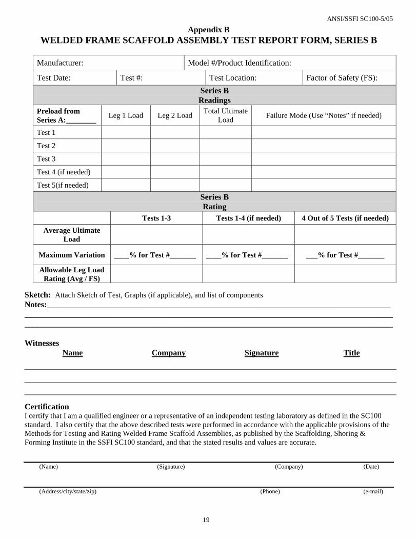
Appendix B WELDED FRAME SCAFFOLD ASSEMBLY TEST REPORT FORM, SERIES B
Manufacturer: Model #/Product Identification:
Test Date: Test #: Test Location: Factor of Safety (FS): Series B Readings
Preload from Series A:________ Leg 1 Load Leg 2 Load Total Ultimate
Load Failure Mode (Use “Notes” if needed)
Test 1
Test 2
Test 3
Test 4 (if needed)
Test 5(if needed)
Series B Rating
Tests 1-3 Tests 1-4 (if needed) 4 Out of 5 Tests (if needed) Average Ultimate
Load
Maximum Variation ____% for Test #_______ ____% for Test #_______ ___% for Test #_______
Allowable Leg Load Rating (Avg / FS)
Sketch: Attach Sketch of Test, Graphs (if applicable), and list of components Notes:________________________________________________________________________________________________________________________________________________________________________________________________________________________________________________________________________ Witnesses
Name Company Signature Title
Certification I certify that I am a qualified engineer or a representative of an independent testing laboratory as defined in the SC100 standard. I also certify that the above described tests were performed in accordance with the applicable provisions of the Methods for Testing and Rating Welded Frame Scaffold Assemblies, as published by the Scaffolding, Shoring & Forming Institute in the SSFI SC100 standard, and that the stated results and values are accurate. (Name) (Signature) (Company) (Date) (Address/city/state/zip) (Phone) (e-mail)

ANSI/SSFI SC100-5/05
20
Appendix C SYSTEM SCAFFOLD ASSEMBLY TEST REPORT FORM, SERIES A
Manufacturer: Model #/Product Identification:
Test Date: Test #: Test Location: Factor of Safety (FS): Series A Readings
Post 1 Load Post 2 Load Post 3 Load Post 4 Load Total Ultimate Load
Failure Mode (Use “Notes”
if needed) Test 1
Test 2
Test 3
Test 4 (if needed)
Test 5(if needed)
Series A Rating
Tests 1-3 Tests 1-4 (if needed) 4 Out of 5 Tests (if needed) Average Ultimate
Load
Maximum Variation ____% for Test #_______ ____% for Test #_______ ___% for Test #_______
Allowable Post Load Rating (Avg / FS)
Sketch: Attach Sketch of Test, Graphs (if applicable), and list of components Notes:________________________________________________________________________________________________________________________________________________________________________________________________________________________________________________________________________ Witnesses
Name Company Signature Title
Certification I certify that I am a qualified engineer or a representative of an independent testing laboratory as defined in the SC100 standard. I also certify that the above described tests were performed in accordance with the applicable provisions of the Methods for Testing and Rating System Scaffold Assemblies, as published by the Scaffolding, Shoring & Forming Institute in the SSFI SC100 standard, and that the stated results and values are accurate. (Name) (Signature) (Company) (Date) (Address/city/state/zip) (Phone) (e-mail)

ANSI/SSFI SC100-5/05
21
Appendix C SYSTEM SCAFFOLD ASSEMBLY TEST REPORT FORM, SERIES B
Manufacturer: Model #/Product Identification:
Test Date: Test #: Test Location: Factor of Safety (FS): Series B Readings
Preload from Series A:________ Post 1 Load Post 2 Load Total Ultimate
Load Failure Mode (Use “Notes” if needed)
Test 1
Test 2
Test 3
Test 4 (if needed)
Test 5(if needed)
Series B Rating
Tests 1-3 Tests 1-4 (if needed) 4 Out of 5 Tests (if needed) Average Ultimate
Load
Maximum Variation ____% for Test #_______ ____% for Test #_______ ___% for Test #_______
Allowable Post Load Rating (Avg / FS)
Sketch: Attach Sketch of Test, Graphs (if applicable), and list of components Notes:________________________________________________________________________________________________________________________________________________________________________________________________________________________________________________________________________ Witnesses
Name Company Signature Title
Certification I certify that I am a qualified engineer or a representative of an independent testing laboratory as defined in the SC100 standard. I also certify that the above described tests were performed in accordance with the applicable provisions of the Methods for Testing and Rating System Scaffold Assemblies, as published by the Scaffolding, Shoring & Forming Institute in the SSFI SC100 standard, and that the stated results and values are accurate. (Name) (Signature) (Company) (Date) (Address/city/state/zip) (Phone) (e-mail)

ANSI/SSFI SC100-5/05
22
Appendix C SYSTEM SCAFFOLD ASSEMBLY TEST REPORT FORM, SERIES C
Manufacturer: Model #/Product Identification:
Test Date: Test #: Test Location: Factor of Safety (FS): Series C Readings
Preload from Series A:________
Center Post / Total Ultimate Load Failure Mode (Use “Notes” if needed)
Test 1
Test 2
Test 3
Test 4 (if needed)
Test 5(if needed)
Series C Rating
Tests 1-3 Tests 1-4 (if needed) 4 Out of 5 Tests (if needed) Average Ultimate
Load
Maximum Variation ____% for Test #_______ ____% for Test #_______ ___% for Test #_______
Allowable Post Load Rating (Avg / FS)
Sketch: Attach Sketch of Test, Graphs (if applicable), and list of components Notes:________________________________________________________________________________________________________________________________________________________________________________________________________________________________________________________________________ Witnesses
Name Company Signature Title
Certification I certify that I am a qualified engineer or a representative of an independent testing laboratory as defined in the SC100 standard. I also certify that the above described tests were performed in accordance with the applicable provisions of the Methods for Testing and Rating System Scaffold Assemblies, as published by the Scaffolding, Shoring & Forming Institute in the SSFI SC100 standard, and that the stated results and values are accurate. (Name) (Signature) (Company) (Date) (Address/city/state/zip) (Phone) (e-mail)

ANSI/SSFI SC100-5/05
23
Appendix D GUARDRAIL SCAFFOLD COMPONENT TEST REPORT FORM
Manufacturer: Model # / Product Identification:
Test Date: Test #: Test Location:
Guardrail Post Test 1 Test 2 Test 3 Test 4 Average
Ultimate Load
Deflection at Ultimate Load
Mode of Failure
Guardrail Test 1 Test 2 Test 3 Test 4 Average Ultimate Load, Outward
Deflection at Ultimate Load
Ultimate Load, Inward
Deflection at Ultimate Load
Ultimate Load, Downward
Deflection at Ultimate Load
Mode of Failure
Sketch: Attach Sketch of Test, Graphs (if applicable), and list of components
Notes:________________________________________________________________________________________________________________________________________________________________________________________________________________________________________________________________________
Witnesses Name Company Signature Title
Certification I certify that I am a qualified engineer or a representative of an independent testing laboratory as defined in the SC100 standard. I also certify that the above described tests were performed in accordance with the applicable provisions of the Methods for Testing Guardrail Scaffold Components, as published by the Scaffolding, Shoring & Forming Institute in the SSFI SC100 standard, and that the stated results and values are accurate. (Name) (Signature) (Company) (Date) (Address/city/state/zip) (Phone) (e-mail)
ANSI/SSFI SC100-5/05
24
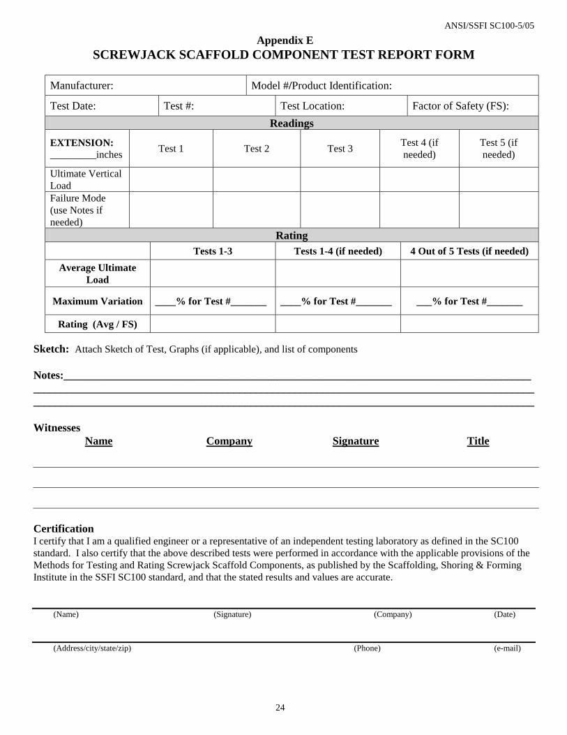
Appendix E SCREWJACK SCAFFOLD COMPONENT TEST REPORT FORM
Manufacturer: Model #/Product Identification:
Test Date: Test #: Test Location: Factor of Safety (FS): Readings
EXTENSION: _________inches Test 1 Test 2 Test 3 Test 4 (if
needed) Test 5 (if needed)
Ultimate Vertical Load
Failure Mode (use Notes if needed)
Rating Tests 1-3 Tests 1-4 (if needed) 4 Out of 5 Tests (if needed)
Average Ultimate Load
Maximum Variation ____% for Test #_______ ____% for Test #_______ ___% for Test #_______
Rating (Avg / FS)
Sketch: Attach Sketch of Test, Graphs (if applicable), and list of components Notes:________________________________________________________________________________________________________________________________________________________________________________________________________________________________________________________________________ Witnesses
Name Company Signature Title
Certification I certify that I am a qualified engineer or a representative of an independent testing laboratory as defined in the SC100 standard. I also certify that the above described tests were performed in accordance with the applicable provisions of the Methods for Testing and Rating Screwjack Scaffold Components, as published by the Scaffolding, Shoring & Forming Institute in the SSFI SC100 standard, and that the stated results and values are accurate. (Name) (Signature) (Company) (Date) (Address/city/state/zip) (Phone) (e-mail)
ANSI/SSFI SC100-5/05
25
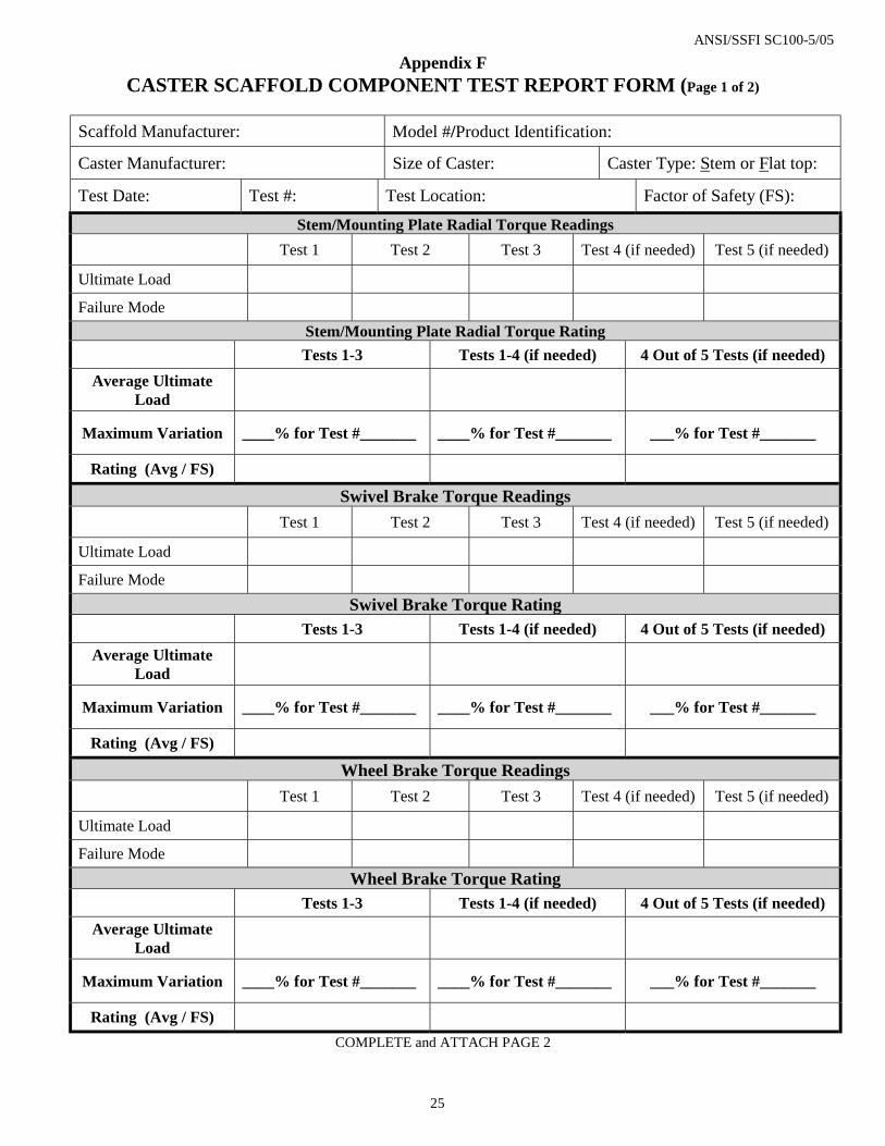
Appendix F CASTER SCAFFOLD COMPONENT TEST REPORT FORM (Page 1 of 2)
Scaffold Manufacturer: Model #/Product Identification:
Caster Manufacturer: Size of Caster: Caster Type: Stem or Flat top:
Test Date: Test #: Test Location: Factor of Safety (FS):
Stem/Mounting Plate Radial Torque Readings
Test 1 Test 2 Test 3 Test 4 (if needed) Test 5 (if needed)
Ultimate Load
Failure Mode
Stem/Mounting Plate Radial Torque Rating
Tests 1-3 Tests 1-4 (if needed) 4 Out of 5 Tests (if needed) Average Ultimate
Load
Maximum Variation ____% for Test #_______ ____% for Test #_______ ___% for Test #_______
Rating (Avg / FS)
Swivel Brake Torque Readings
Test 1 Test 2 Test 3 Test 4 (if needed) Test 5 (if needed)
Ultimate Load
Failure Mode
Swivel Brake Torque Rating Tests 1-3 Tests 1-4 (if needed) 4 Out of 5 Tests (if needed)
Average Ultimate Load
Maximum Variation ____% for Test #_______ ____% for Test #_______ ___% for Test #_______
Rating (Avg / FS)
Wheel Brake Torque Readings
Test 1 Test 2 Test 3 Test 4 (if needed) Test 5 (if needed)
Ultimate Load
Failure Mode
Wheel Brake Torque Rating Tests 1-3 Tests 1-4 (if needed) 4 Out of 5 Tests (if needed)
Average Ultimate Load
Maximum Variation ____% for Test #_______ ____% for Test #_______ ___% for Test #_______
Rating (Avg / FS)
COMPLETE and ATTACH PAGE 2

ANSI/SSFI SC100-5/05
26
Appendix F CASTER SCAFFOLD COMPONENT TEST REPORT FORM (Page 2 of 2)
Caster Vertical Load Readings
Test 1 Test 2 Test 3 Test 4 (if needed) Test 5 (if needed)
Ultimate Load
Failure Mode
Caster Vertical Load Rating Tests 1-3 Tests 1-4 (if needed) 4 Out of 5 Tests (if needed)
Average Ultimate Load
Maximum Variation ____% for Test #_______ ____% for Test #_______ ___% for Test #_______
Rating (Avg / FS)
Sketch: Attach Sketch of Test, Graphs (if applicable), and list of components Notes:________________________________________________________________________________________________________________________________________________________________________________________________________________________________________________________________________ Witnesses
Name Company Signature Title
Certification I certify that I am a qualified engineer or a representative of an independent testing laboratory as defined in the SC100 standard. I also certify that the above described tests were performed in accordance with the applicable provisions of the Methods for Testing and Rating Caster Scaffold Components, as published by the Scaffolding, Shoring & Forming Institute in the SSFI SC100 standard, and that the stated results and values are accurate. (Name) (Signature) (Company) (Date) (Address/city/state/zip) (Phone) (e-mail)

ANSI/SSFI SC100-5/05
27
Appendix G PUTLOG SCAFFOLD ASSEMBLY TEST REPORT FORM
Scaffold Manufacturer: Model #/Product Identification:
Test Date: Test #: Test Location: Factor of Safety (FS):
Platform Material Weight How Is Load Applied (media or machine?):
Putlog Span Readings
Test 1 Test 2 Test 3 Test 4 (if needed) Test 5 (if needed)
Ultimate Load
Failure Mode
Rating Tests 1-3 Tests 1-4 (if needed) 4 Out of 5 Tests (if needed)
Average Ultimate Load
Maximum Variation ____% for Test #_______ ____% for Test #_______ ___% for Test #_______
Rating (Avg / FS)
Sketch: Attach Sketch of Test, Graphs (if applicable), and list of components
Notes:________________________________________________________________________________________________________________________________________________________________________________________________________________________________________________________________________
Witnesses Name Company Signature Title
Certification I certify that I am a qualified engineer or a representative of an independent testing laboratory as defined in the SC100 standard. I also certify that the above described tests were performed in accordance with the applicable provisions of the Methods of Testing and Rating Putlog Scaffold Assemblies, as published by the Scaffolding, Shoring & Forming Institute in the SSFI SC100 standard, and that the stated results and values are accurate. (Name) (Signature) (Company) (Date) (Address/city/state/zip) (Phone) (e-mail)

ANSI/SSFI SC100-5/05
28
Appendix H SIDE and END BRACKET SCAFFOLD COMPONENT TEST REPORT FORM
Manufacturer: Model #/Product Identification:
Test Date: Test #: Test Location: Factor of Safety (FS):
Diameter of Tube on Which Bracket Rests: Cantilever Length of Bracket:
Depth of Bracket: Hooked or Simply Supported Platform: Platform Materials Weight: Readings
Test 1 Test 2 Test 3 Test 4 (if needed) Test 5 (if needed)
Ultimate Load
Failure Mode
Rating Tests 1-3 Tests 1-4 (if needed) 4 Out of 5 Tests (if needed)
Average Ultimate Load
Maximum Variation ____% for Test #_______ ____% for Test #_______ ___% for Test #_______
Rating (Avg / FS)
Sketch: Attach Sketch of Test, Graphs (if applicable), and list of components
Notes:________________________________________________________________________________________________________________________________________________________________________________________________________________________________________________________________________
Witnesses Name Company Signature Title
Certification I certify that I am a qualified engineer or a representative of an independent testing laboratory as defined in the SC100 standard. I also certify that the above described tests were performed in accordance with the applicable provisions of the Methods for Testing and Rating Side and End Bracket Scaffold Components, as published by the Scaffolding, Shoring & Forming Institute in the SSFI SC100 standard, and that the stated results and values are accurate. (Name) (Signature) (Company) (Date) (Address/city/state/zip) (Phone) (e-mail)

ANSI/SSFI SC100-5/05
29
Figures
Figure 5.1A

ANSI/SSFI SC100-5/05
30
Figure 5.1B
Figure 5.1C

ANSI/SSFI SC100-5/05
31
Figure 5.1D

ANSI/SSFI SC100-5/05
32
Figure 5.2A

ANSI/SSFI SC100-5/05
33
Figure 5.2B

ANSI/SSFI SC100-5/05
34
Figure 5.3A
1.5M Nominal
2M Nominal
ANSI/SSFI SC100-5/05
35
Figure 5.3B
2M Nominal
2M Nominal
1.5M Nominal
ANSI/SSFI SC100-5/05
36
Figure 5.3C
1.5M Nominal
1.5M Nom.
2M Nom. 2M
Nominal

ANSI/SSFI SC100-5/05
37
Figure 5.4B
Figure 5.4C
Figure 5.4A

ANSI/SSFI SC100-5/05
38
Figure 5.5A

ANSI/SSFI SC100-5/05
39
Figure 5.6A Figure 5.6B
Figure 5.6C Figure 5.6D

ANSI/SSFI SC100-5/05
40
Figure 5.6E Figure 5.6F
Figure 5.6G

ANSI/SSFI SC100-5/05
41
Figure 5.7A
Figure 5.8A

ANSI/SSFI SC100-5/05
42
Figure 5.8B