Embed Size (px)
Citation preview
Designation: D 143 – 94 (Reapproved 2000) e1
Standard Test Methods forSmall Clear Specimens of Timber 1
This standard is issued under the fixed designation D 143; the number immediately following the designation indicates the year oforiginal adoption or, in the case of revision, the year of last revision. A number in parentheses indicates the year of last reapproval. Asuperscript epsilon (e) indicates an editorial change since the last revision or reapproval.
This standard has been approved for use by agencies of the Department of Defense.
e1 NOTE—Keywords were added in April 2000.
INTRODUCTION
The need to classify wood species by evaluating the physical and mechanical properties of smallclear specimens has always existed. Because of the great variety of species, variability of the material,continually changing conditions of supply, many factors affecting test results, and ease of comparingvariables, the need will undoubtedly continue to exist.
In the preparation of these methods for testing small clear specimens, consideration was given bothto the desirability of adopting methods that would yield results comparable to those already availableand to the possibility of embodying such improvements as experience has shown desirable. In viewof the many thousands of tests made under a single comprehensive plan by the U.S. Forest Service,the former Forest Products Laboratories of Canada (now Forintek Canada Corp.), and other similarorganizations, the methods naturally conform closely to the methods used by these institutions. Thesemethods are the outgrowth of a study of both American and European experience and methods. Thegeneral adoption of these methods will tend toward a world-wide unification of results, permitting aninterchange and correlation of data, and establishing the basis for a cumulative body of fundamentalinformation on the timber species of the world.
Descriptions of some of the strength tests refer to primary methods and secondary methods. Primarymethods provide for specimens of 2 by 2-in. (50 by 50-mm) cross-section. This size of specimen hasbeen extensively used for the evaluation of various mechanical and physical properties of differentspecies of wood, and a large number of data based on this primary method have been obtained andpublished.
The 2 by 2-in. (50 by 50-mm) size has the advantage in that it embraces a number of growth rings,is less influenced by earlywood and latewood differences than smaller size specimens, and is largeenough to represent a considerable portion of the sampled material. It is advisable to use primarymethod specimens wherever possible. There are circumstances, however, when it is difficult orimpossible to obtain clear specimens of 2 by 2-in. cross section having the required 30 in. (760 mm)length for static bending tests. With the increasing incidence of smaller second growth trees, and thedesirability in certain situations to evaluate a material which is too small to provide a 2 by 2-in.cross-section, a secondary method which utilizes a 1 by1-in. (25 by 25-mm) cross section has beenincluded. This cross section is established for compression parallel to grain and static bending tests,while the 2 by 2-in. cross-section is retained for impact bending, compression perpendicular to grain,hardness, shear parallel to grain, cleavage, and tension perpendicular to grain. Toughness and tensionparallel to grain are special tests using specimens of smaller cross section.
The user is cautioned that test results between two different sizes of specimens are not necessarilydirectly comparable. Guidance on the effect of specimen size on a property being evaluated is beyondthe scope of these methods, and should be sought elsewhere.
Where the application, measurement, or recording of load and deflection can be accomplished usingelectronic equipment and computerized apparatus, such devices are encouraged, providing they do notlower the standard of accuracy and reliability available with basic mechanical equipment.
1
Copyright © ASTM International, 100 Barr Harbor Drive, PO Box C700, West Conshohocken, PA 19428-2959, United States.
1. Scope
1.1 These methods cover the determination of variousstrength and related properties of wood by testing small clearspecimens.
1.1.1 These methods represent procedures for evaluating thedifferent mechanical and physical properties, controlling fac-tors such as specimen size, moisture content, temperature, andrate of loading.
1.1.2 Sampling and collection of material is discussed inPractice D 5536. Sample data, computation sheets, and cardshave been incorporated, which were of assistance to theinvestigator in systematizing records.
1.1.3 The values stated in inch-pound units are to beregarded as the standard. The SI values are given in parenthe-ses and are provided for information only. When a weight isprescribed, the basic inch-pound unit of weight (lbf) and thebasic SI unit of mass (Kg) are cited.
1.2 The procedures for the various tests appear in thefollowing order:
SectionsPhotographs of Specimens 5Control of Moisture Content and Temperature 6Record of Heartwood and Sapwood 7Static Bending 8Compression Parallel to Grain 9Impact Bending 10Toughness 11Compression Perpendicular to Grain 12Hardness 13Shear Parallel to Grain 14Cleavage 15Tension Parallel to Grain 16Tension Perpendicular to Grain 17Nail Withdrawal 18Specific Gravity and Shrinkage in Volume 19Radial and Tangential Shrinkage 20Moisture Determination 21Permissible Variations 22Calibration 23
1.3 This standard does not purport to address all of thesafety concerns, if any, associated with its use. It is theresponsibility of the user of this standard to establish appro-priate safety and health practices and determine the applica-bility of regulatory limitations prior to use.
2. Referenced Documents
2.1 ASTM Standards:D 198 Methods for Static Tests of Timbers in Structural
Sizes2
D 2395 Test Methods for Specific Gravity of Wood andWood-Base Materials2
D 3043 Methods of Testing Structural Panels in Flexure2
D 3500 Test Method for Structural Panels in Tension2
D 4442 Test Methods for Direct Moisture Content Measure-ment of Wood and Wood-Base Materials2
D 4761 Test Method for Mechanical Properties of Lumberand Wood-Base Structural Material2
D 5536 Practice for Sampling the Forest Trees for Determi-nation of Clear Wood Properties2
E 4 Practices for Force Verification of Testing Machines3
3. Summary of Methods
3.1 The mechanical tests are static bending, compressionparallel to grain, impact bending toughness, compressionperpendicular to grain, hardness, shear parallel to grain (Note1), cleavage, tension parallel to grain, tension-perpendicular-to-grain, and nail-withdrawal tests. These tests may be made onboth green and air-dry material as specified in these methods.In addition, methods for evaluating such physical properties asspecific gravity, shrinkage in volume, radial shrinkage, andtangential shrinkage are presented.
NOTE 1—The test for shearing strength perpendicular to the grain(sometimes termed “vertical shear”) is not included as one of the principalmechanical tests since in such a test the strength is limited by the shearingresistance parallel to the grain.
4. Significance and Use
4.1 These methods cover tests on small clear specimens ofwood that are made to provide the following:
4.1.1 Data for comparing the mechanical properties ofvarious species,
4.1.2 Data for the establishment of correct strength func-tions, which in conjunction with results of tests of timbers instructural sizes (see Methods D 198 and Test Method D 4761),afford a basis for establishing allowable stresses, and
4.1.3 Data to determine the influence on the mechanicalproperties of such factors as density, locality of growth,position in cross section, height of timber in the tree, change ofproperties with seasoning or treatment with chemicals, andchange from sapwood to heartwood.
5. Photographs of Specimens
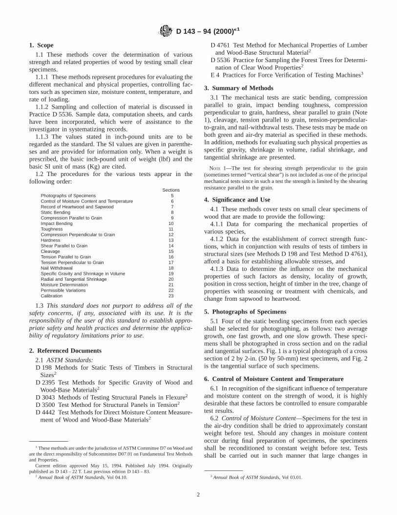
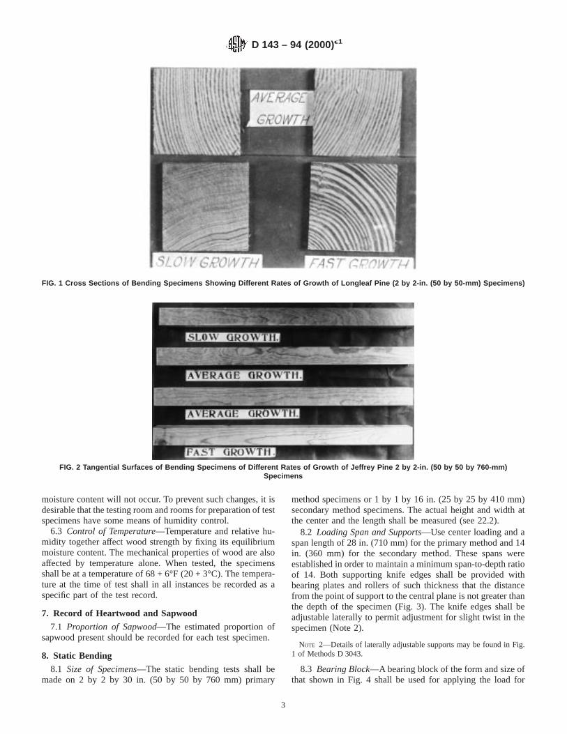
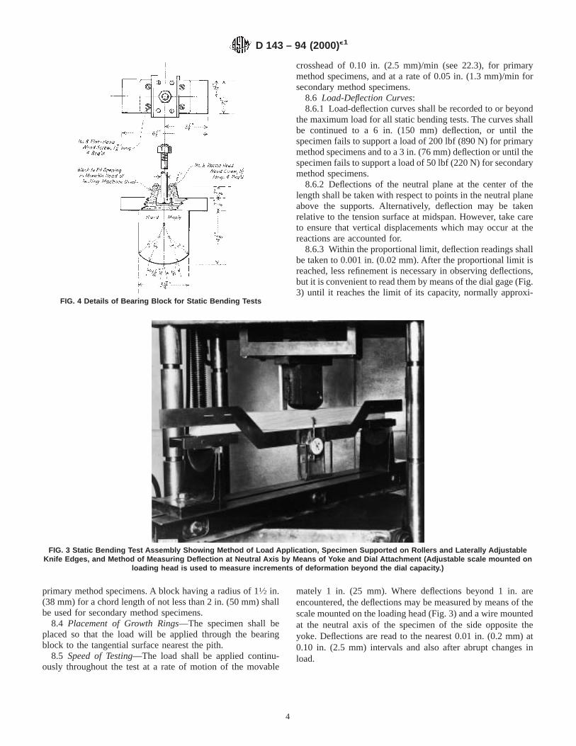
5.1 Four of the static bending specimens from each speciesshall be selected for photographing, as follows: two averagegrowth, one fast growth, and one slow growth. These speci-mens shall be photographed in cross section and on the radialand tangential surfaces. Fig. 1 is a typical photograph of a crosssection of 2 by 2-in. (50 by 50-mm) test specimens, and Fig. 2is the tangential surface of such specimens.
6. Control of Moisture Content and Temperature
6.1 In recognition of the significant influence of temperatureand moisture content on the strength of wood, it is highlydesirable that these factors be controlled to ensure comparabletest results.
6.2 Control of Moisture Content—Specimens for the test inthe air-dry condition shall be dried to approximately constantweight before test. Should any changes in moisture contentoccur during final preparation of specimens, the specimensshall be reconditioned to constant weight before test. Testsshall be carried out in such manner that large changes in
1 These methods are under the jurisdiction of ASTM Committee D7 on Wood andare the direct responsibility of Subcommittee D07.01 on Fundamental Test Methodsand Properties.
Current edition approved May 15, 1994. Published July 1994. Originallypublished as D 143 – 22 T. Last previous edition D 143 – 83.
2 Annual Book of ASTM Standards, Vol 04.10. 3 Annual Book of ASTM Standards, Vol 03.01.
D 143 – 94 (2000)e1
2
moisture content will not occur. To prevent such changes, it isdesirable that the testing room and rooms for preparation of testspecimens have some means of humidity control.
6.3 Control of Temperature—Temperature and relative hu-midity together affect wood strength by fixing its equilibriummoisture content. The mechanical properties of wood are alsoaffected by temperature alone. When tested, the specimensshall be at a temperature of 68 + 6°F (20 + 3°C). The tempera-ture at the time of test shall in all instances be recorded as aspecific part of the test record.
7. Record of Heartwood and Sapwood
7.1 Proportion of Sapwood—The estimated proportion ofsapwood present should be recorded for each test specimen.
8. Static Bending
8.1 Size of Specimens—The static bending tests shall bemade on 2 by 2 by 30 in. (50 by 50 by 760 mm) primary
method specimens or 1 by 1 by 16 in. (25 by 25 by 410 mm)secondary method specimens. The actual height and width atthe center and the length shall be measured (see 22.2).
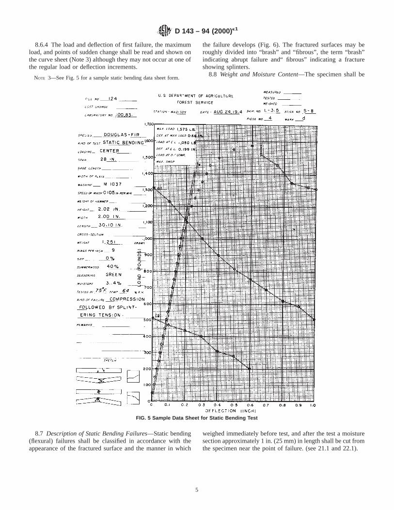
8.2 Loading Span and Supports—Use center loading and aspan length of 28 in. (710 mm) for the primary method and 14in. (360 mm) for the secondary method. These spans wereestablished in order to maintain a minimum span-to-depth ratioof 14. Both supporting knife edges shall be provided withbearing plates and rollers of such thickness that the distancefrom the point of support to the central plane is not greater thanthe depth of the specimen (Fig. 3). The knife edges shall beadjustable laterally to permit adjustment for slight twist in thespecimen (Note 2).
NOTE 2—Details of laterally adjustable supports may be found in Fig.1 of Methods D 3043.
8.3 Bearing Block—A bearing block of the form and size ofthat shown in Fig. 4 shall be used for applying the load for
FIG. 1 Cross Sections of Bending Specimens Showing Different Rates of Growth of Longleaf Pine (2 by 2-in. (50 by 50-mm) Specimens)
FIG. 2 Tangential Surfaces of Bending Specimens of Different Rates of Growth of Jeffrey Pine 2 by 2-in. (50 by 50 by 760-mm)Specimens
D 143 – 94 (2000)e1
3
primary method specimens. A block having a radius of 11⁄2 in.(38 mm) for a chord length of not less than 2 in. (50 mm) shallbe used for secondary method specimens.
8.4 Placement of Growth Rings—The specimen shall beplaced so that the load will be applied through the bearingblock to the tangential surface nearest the pith.
8.5 Speed of Testing—The load shall be applied continu-ously throughout the test at a rate of motion of the movable
crosshead of 0.10 in. (2.5 mm)/min (see 22.3), for primarymethod specimens, and at a rate of 0.05 in. (1.3 mm)/min forsecondary method specimens.
8.6 Load-Deflection Curves:8.6.1 Load-deflection curves shall be recorded to or beyond
the maximum load for all static bending tests. The curves shallbe continued to a 6 in. (150 mm) deflection, or until thespecimen fails to support a load of 200 lbf (890 N) for primarymethod specimens and to a 3 in. (76 mm) deflection or until thespecimen fails to support a load of 50 lbf (220 N) for secondarymethod specimens.
8.6.2 Deflections of the neutral plane at the center of thelength shall be taken with respect to points in the neutral planeabove the supports. Alternatively, deflection may be takenrelative to the tension surface at midspan. However, take careto ensure that vertical displacements which may occur at thereactions are accounted for.
8.6.3 Within the proportional limit, deflection readings shallbe taken to 0.001 in. (0.02 mm). After the proportional limit isreached, less refinement is necessary in observing deflections,but it is convenient to read them by means of the dial gage (Fig.3) until it reaches the limit of its capacity, normally approxi-
mately 1 in. (25 mm). Where deflections beyond 1 in. areencountered, the deflections may be measured by means of thescale mounted on the loading head (Fig. 3) and a wire mountedat the neutral axis of the specimen of the side opposite theyoke. Deflections are read to the nearest 0.01 in. (0.2 mm) at0.10 in. (2.5 mm) intervals and also after abrupt changes inload.
FIG. 4 Details of Bearing Block for Static Bending Tests
FIG. 3 Static Bending Test Assembly Showing Method of Load Application, Specimen Supported on Rollers and Laterally AdjustableKnife Edges, and Method of Measuring Deflection at Neutral Axis by Means of Yoke and Dial Attachment (Adjustable scale mounted on
loading head is used to measure increments of deformation beyond the dial capacity.)
D 143 – 94 (2000)e1
4
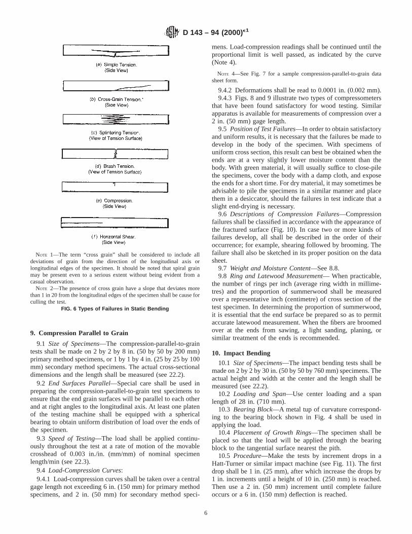
8.6.4 The load and deflection of first failure, the maximumload, and points of sudden change shall be read and shown onthe curve sheet (Note 3) although they may not occur at one ofthe regular load or deflection increments.
NOTE 3—See Fig. 5 for a sample static bending data sheet form.
8.7 Description of Static Bending Failures—Static bending(flexural) failures shall be classified in accordance with theappearance of the fractured surface and the manner in which
the failure develops (Fig. 6). The fractured surfaces may beroughly divided into “brash” and “fibrous”, the term “brash”indicating abrupt failure and“ fibrous” indicating a fractureshowing splinters.
8.8 Weight and Moisture Content—The specimen shall be
weighed immediately before test, and after the test a moisturesection approximately 1 in. (25 mm) in length shall be cut fromthe specimen near the point of failure. (see 21.1 and 22.1).
FIG. 5 Sample Data Sheet for Static Bending Test
D 143 – 94 (2000)e1
5
9. Compression Parallel to Grain
9.1 Size of Specimens—The compression-parallel-to-graintests shall be made on 2 by 2 by 8 in. (50 by 50 by 200 mm)primary method specimens, or 1 by 1 by 4 in. (25 by 25 by 100mm) secondary method specimens. The actual cross-sectionaldimensions and the length shall be measured (see 22.2).
9.2 End Surfaces Parallel—Special care shall be used inpreparing the compression-parallel-to-grain test specimens toensure that the end grain surfaces will be parallel to each otherand at right angles to the longitudinal axis. At least one platenof the testing machine shall be equipped with a sphericalbearing to obtain uniform distribution of load over the ends ofthe specimen.
9.3 Speed of Testing—The load shall be applied continu-ously throughout the test at a rate of motion of the movablecrosshead of 0.003 in./in. (mm/mm) of nominal specimenlength/min (see 22.3).
9.4 Load-Compression Curves:9.4.1 Load-compression curves shall be taken over a central
gage length not exceeding 6 in. (150 mm) for primary methodspecimens, and 2 in. (50 mm) for secondary method speci-
mens. Load-compression readings shall be continued until theproportional limit is well passed, as indicated by the curve(Note 4).
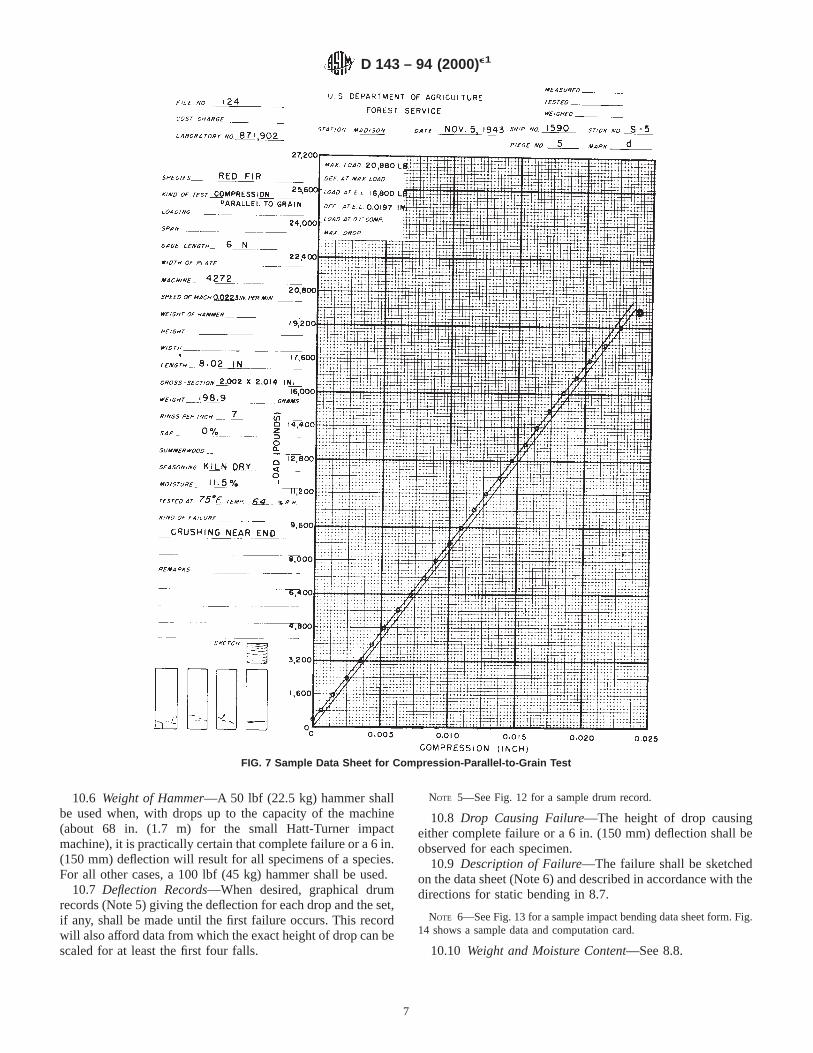
NOTE 4—See Fig. 7 for a sample compression-parallel-to-grain datasheet form.
9.4.2 Deformations shall be read to 0.0001 in. (0.002 mm).9.4.3 Figs. 8 and 9 illustrate two types of compressometers
that have been found satisfactory for wood testing. Similarapparatus is available for measurements of compression over a2 in. (50 mm) gage length.
9.5 Position of Test Failures—In order to obtain satisfactoryand uniform results, it is necessary that the failures be made todevelop in the body of the specimen. With specimens ofuniform cross section, this result can best be obtained when theends are at a very slightly lower moisture content than thebody. With green material, it will usually suffice to close-pilethe specimens, cover the body with a damp cloth, and exposethe ends for a short time. For dry material, it may sometimes beadvisable to pile the specimens in a similar manner and placethem in a desiccator, should the failures in test indicate that aslight end-drying is necessary.
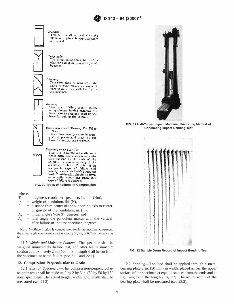
9.6 Descriptions of Compression Failures—Compressionfailures shall be classified in accordance with the appearance ofthe fractured surface (Fig. 10). In case two or more kinds offailures develop, all shall be described in the order of theiroccurrence; for example, shearing followed by brooming. Thefailure shall also be sketched in its proper position on the datasheet.
9.7 Weight and Moisture Content—See 8.8.9.8 Ring and Latewood Measurement— When practicable,
the number of rings per inch (average ring width in millime-tres) and the proportion of summerwood shall be measuredover a representative inch (centimetre) of cross section of thetest specimen. In determining the proportion of summerwood,it is essential that the end surface be prepared so as to permitaccurate latewood measurement. When the fibers are broomedover at the ends from sawing, a light sanding, planing, orsimilar treatment of the ends is recommended.
10. Impact Bending
10.1 Size of Specimens—The impact bending tests shall bemade on 2 by 2 by 30 in. (50 by 50 by 760 mm) specimens. Theactual height and width at the center and the length shall bemeasured (see 22.2).
10.2 Loading and Span—Use center loading and a spanlength of 28 in. (710 mm).
10.3 Bearing Block—A metal tup of curvature correspond-ing to the bearing block shown in Fig. 4 shall be used inapplying the load.
10.4 Placement of Growth Rings—The specimen shall beplaced so that the load will be applied through the bearingblock to the tangential surface nearest the pith.
10.5 Procedure—Make the tests by increment drops in aHatt-Turner or similar impact machine (see Fig. 11). The firstdrop shall be 1 in. (25 mm), after which increase the drops by1 in. increments until a height of 10 in. (250 mm) is reached.Then use a 2 in. (50 mm) increment until complete failureoccurs or a 6 in. (150 mm) deflection is reached.
NOTE 1—The term “cross grain” shall be considered to include alldeviations of grain from the direction of the longitudinal axis orlongitudinal edges of the specimen. It should be noted that spiral grainmay be present even to a serious extent without being evident from acasual observation.
NOTE 2—The presence of cross grain have a slope that deviates morethan 1 in 20 from the longitudinal edges of the specimen shall be cause forculling the test.
FIG. 6 Types of Failures in Static Bending
D 143 – 94 (2000)e1
6
10.6 Weight of Hammer—A 50 lbf (22.5 kg) hammer shallbe used when, with drops up to the capacity of the machine(about 68 in. (1.7 m) for the small Hatt-Turner impactmachine), it is practically certain that complete failure or a 6 in.(150 mm) deflection will result for all specimens of a species.For all other cases, a 100 lbf (45 kg) hammer shall be used.
10.7 Deflection Records—When desired, graphical drumrecords (Note 5) giving the deflection for each drop and the set,if any, shall be made until the first failure occurs. This recordwill also afford data from which the exact height of drop can bescaled for at least the first four falls.
NOTE 5—See Fig. 12 for a sample drum record.
10.8 Drop Causing Failure—The height of drop causingeither complete failure or a 6 in. (150 mm) deflection shall beobserved for each specimen.
10.9 Description of Failure—The failure shall be sketchedon the data sheet (Note 6) and described in accordance with thedirections for static bending in 8.7.
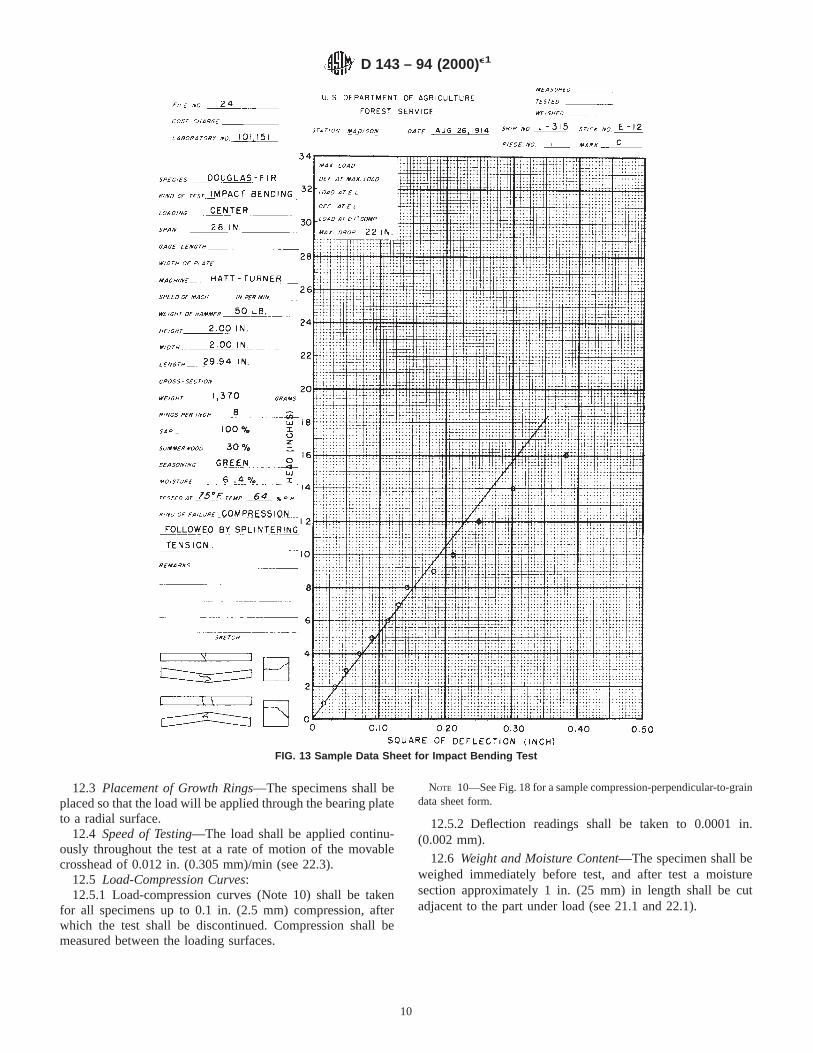
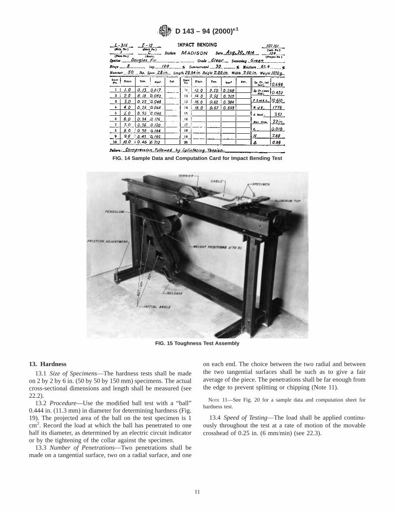
NOTE 6—See Fig. 13 for a sample impact bending data sheet form. Fig.14 shows a sample data and computation card.
10.10 Weight and Moisture Content—See 8.8.
FIG. 7 Sample Data Sheet for Compression-Parallel-to-Grain Test
D 143 – 94 (2000)e1
7
11. Toughness
11.1 A single-blow impact test on a small specimen isrecognized as a valuable and desirable test. Several types ofmachines such as the Toughness, Izod and Amsler have beenused, but insufficient information is available to decide whetherone procedure is superior to another, or whether the results bythe different methods can be directly correlated. If the Tough-ness machine is used, the following procedure has been found
satisfactory. To aid in standardization and to facilitate compari-sons, the size of the toughness specimen has been made equalto that accepted internationally.
11.2 Size of Specimen—The toughness tests shall be madeon 0.79 by 0.79 by 11 in. (20 by 20 by 280 mm) specimens.The actual height and width at the center and the length shallbe measured (see 22.2).
11.3 Loading and Span—Center loading and a span lengthof 9.47 in. (240 mm) shall be used. The load shall be appliedto a radial or tangential surface on alternate specimens.
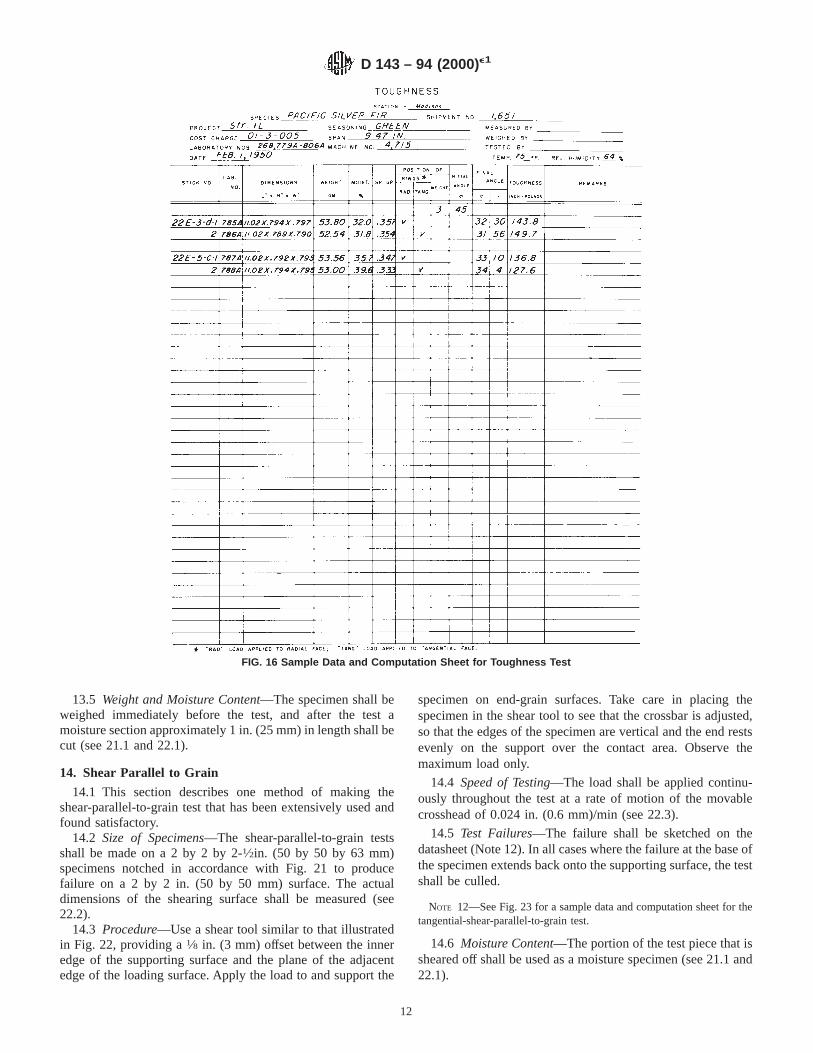
11.4 Bearing Block—An aluminum tup (Fig. 15) having aradius of3⁄4 in. (19 mm) shall be used in applying the load.
11.5 Apparatus and Procedure—Make the tests in a pendu-lum type toughness machine (Note 7) (See Fig. 15). Adjust themachine before test so that the pendulum hangs vertically, andadjust it to compensate for friction. Adjust the cable so that theload is applied to the specimen when the pendulum swings to15° from the vertical, so as to produce complete failure by thetime the downward swing is completed. Choose the weightposition and initial angle (30, 45, or 60°) of the pendulum, sothat complete failure of the specimen is obtained on one drop.Most satisfactory results are obtained when the differencebetween the initial and final angle is at least 10°.
NOTE 7—Many pendulum-type toughness machines are based on adesign developed and used at the USDA Forest Products Laboratory inMadison, Wisconsin.
11.6 Calculation—The initial and final angle shall be readto the nearest 0.1° by means of the vernier (Fig. 15) attached tothe machine (Note 8).
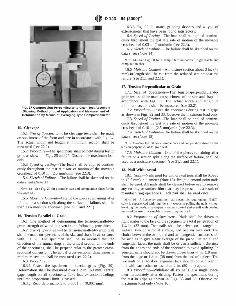
NOTE 8—See Fig. 16 for sample data and computation sheet for thetoughness test.
The toughness shall then be calculated as follows:
T 5 wL~cos A2 2 cos A1! (1)
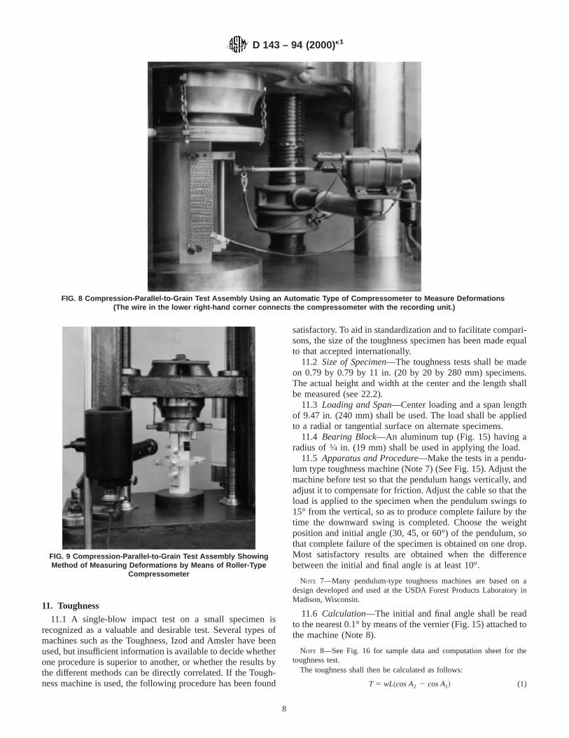
FIG. 8 Compression-Parallel-to-Grain Test Assembly Using an Automatic Type of Compressometer to Measure Deformations(The wire in the lower right-hand corner connects the compressometer with the recording unit.)
FIG. 9 Compression-Parallel-to-Grain Test Assembly ShowingMethod of Measuring Deformations by Means of Roller-Type
Compressometer
D 143 – 94 (2000)e1
8
where:T = toughness (work per specimen, in. ·lbf (Nm),w = weight of pendulum, lbf (N),L = distance from center of the supporting axis to center
of gravity of the pendulum, in. (m),A1 = initial angle (Note 9), degrees, andA2 = final angle the pendulum makes with the vertical
after failure of the test specimen, degrees.
NOTE 9—Since friction is compensated for in the machine adjustment,the initial angle may be regarded as exactly 30, 45, or 60°, as the case maybe.
11.7 Weight and Moisture Content—The specimen shall beweighed immediately before test, and after test a moisturesection approximately 2 in. (50 mm) in length shall be cut fromthe specimen near the failure (see 21.1 and 22.1).
12. Compression Perpendicular to Grain
12.1 Size of Specimens—The compression-perpendicular-to-grain tests shall be made on 2 by 2 by 6 in. (50 by 50 by 150mm) specimens. The actual height, width, and length shall bemeasured (see 22.2).
12.2 Loading—The load shall be applied through a metalbearing plate 2 in. (50 mm) in width, placed across the uppersurface of the specimen at equal distances from the ends and atright angles to the length (Fig. 17). The actual width of thebearing plate shall be measured (see 22.2).
FIG. 10 Types of Failures in Compression
FIG. 11 Hatt-Turner Impact Machine, Illustrating Method ofConducting Impact Bending Test
FIG. 12 Sample Drum Record of Impact Bending Test
D 143 – 94 (2000)e1
9
12.3 Placement of Growth Rings—The specimens shall beplaced so that the load will be applied through the bearing plateto a radial surface.
12.4 Speed of Testing—The load shall be applied continu-ously throughout the test at a rate of motion of the movablecrosshead of 0.012 in. (0.305 mm)/min (see 22.3).
12.5 Load-Compression Curves:12.5.1 Load-compression curves (Note 10) shall be taken
for all specimens up to 0.1 in. (2.5 mm) compression, afterwhich the test shall be discontinued. Compression shall bemeasured between the loading surfaces.
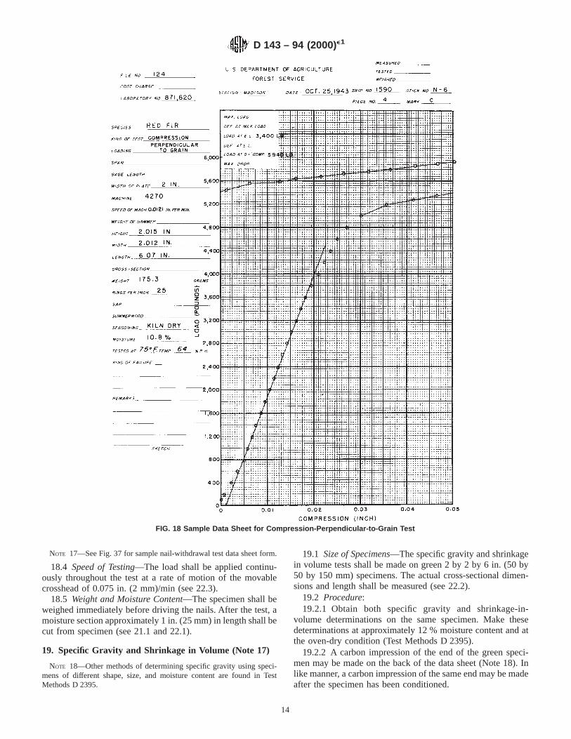
NOTE 10—See Fig. 18 for a sample compression-perpendicular-to-graindata sheet form.
12.5.2 Deflection readings shall be taken to 0.0001 in.(0.002 mm).
12.6 Weight and Moisture Content—The specimen shall beweighed immediately before test, and after test a moisturesection approximately 1 in. (25 mm) in length shall be cutadjacent to the part under load (see 21.1 and 22.1).
FIG. 13 Sample Data Sheet for Impact Bending Test
D 143 – 94 (2000)e1
10
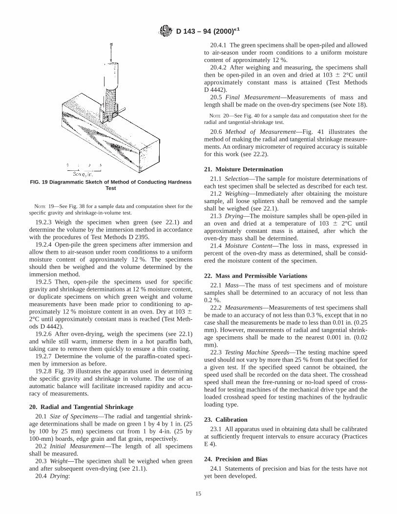
13. Hardness
13.1 Size of Specimens—The hardness tests shall be madeon 2 by 2 by 6 in. (50 by 50 by 150 mm) specimens. The actualcross-sectional dimensions and length shall be measured (see22.2).
13.2 Procedure—Use the modified ball test with a “ball”0.444 in. (11.3 mm) in diameter for determining hardness (Fig.19). The projected area of the ball on the test specimen is 1cm2. Record the load at which the ball has penetrated to onehalf its diameter, as determined by an electric circuit indicatoror by the tightening of the collar against the specimen.
13.3 Number of Penetrations—Two penetrations shall bemade on a tangential surface, two on a radial surface, and one
on each end. The choice between the two radial and betweenthe two tangential surfaces shall be such as to give a fairaverage of the piece. The penetrations shall be far enough fromthe edge to prevent splitting or chipping (Note 11).
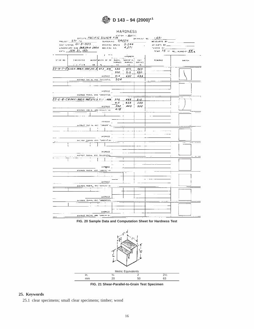
NOTE 11—See Fig. 20 for a sample data and computation sheet forhardness test.
13.4 Speed of Testing—The load shall be applied continu-ously throughout the test at a rate of motion of the movablecrosshead of 0.25 in. (6 mm/min) (see 22.3).
FIG. 14 Sample Data and Computation Card for Impact Bending Test
FIG. 15 Toughness Test Assembly
D 143 – 94 (2000)e1
11
13.5 Weight and Moisture Content—The specimen shall beweighed immediately before the test, and after the test amoisture section approximately 1 in. (25 mm) in length shall becut (see 21.1 and 22.1).
14. Shear Parallel to Grain
14.1 This section describes one method of making theshear-parallel-to-grain test that has been extensively used andfound satisfactory.
14.2 Size of Specimens—The shear-parallel-to-grain testsshall be made on a 2 by 2 by 2-1⁄2in. (50 by 50 by 63 mm)specimens notched in accordance with Fig. 21 to producefailure on a 2 by 2 in. (50 by 50 mm)surface. The actualdimensions of the shearing surface shall be measured (see22.2).
14.3 Procedure—Use a shear tool similar to that illustratedin Fig. 22, providing a1⁄8 in. (3 mm) offset between the inneredge of the supporting surface and the plane of the adjacentedge of the loading surface. Apply the load to and support the
specimen on end-grain surfaces. Take care in placing thespecimen in the shear tool to see that the crossbar is adjusted,so that the edges of the specimen are vertical and the end restsevenly on the support over the contact area. Observe themaximum load only.
14.4 Speed of Testing—The load shall be applied continu-ously throughout the test at a rate of motion of the movablecrosshead of 0.024 in. (0.6 mm)/min (see 22.3).
14.5 Test Failures—The failure shall be sketched on thedatasheet (Note 12). In all cases where the failure at the base ofthe specimen extends back onto the supporting surface, the testshall be culled.
NOTE 12—See Fig. 23 for a sample data and computation sheet for thetangential-shear-parallel-to-grain test.
14.6 Moisture Content—The portion of the test piece that issheared off shall be used as a moisture specimen (see 21.1 and22.1).
FIG. 16 Sample Data and Computation Sheet for Toughness Test
D 143 – 94 (2000)e1
12
15. Cleavage
15.1 Size of Specimens—The cleavage tests shall be madeon specimens of the form and size in accordance with Fig. 24.The actual width and length at minimum section shall bemeasured (see 22.2).
15.2 Procedure—The specimens shall be held during test ingrips as shown in Figs. 25 and 26. Observe the maximum loadonly.
15.3 Speed of Testing—The load shall be applied continu-ously throughout the test at a rate of motion of the movablecrosshead of 0.10 in. (2.5 mm)/min (see 22.3).
15.4 Sketch of Failure—The failure shall be sketched on thedata sheet (Note 13).
NOTE 13—See Fig. 27 for a sample data and computation sheet for thecleavage test.
15.5 Moisture Content—One of the pieces remaining afterfailure, or a section split along the surface of failure, shall beused as a moisture specimen (see 21.1 and 22.1).
16. Tension Parallel to Grain
16.1 One method of determining the tension-parallel-to-grain strength of wood is given in the following procedure.
16.2 Size of Specimens—The tension-parallel-to-grain testsshall be made on specimens of the size and shape in accordancewith Fig. 28. The specimen shall be so oriented that thedirection of the annual rings at the critical section on the endsof the specimens, shall be perpendicular to the greater cross-sectional dimension. The actual cross-sectional dimensions atminimum section shall be measured (see 22.2).
16.3 Procedure:16.3.1 Fasten the specimen in special grips (Fig. 29).
Deformation shall be measured over a 2 in. (50 mm) centralgage length on all specimens. Take load-extension readingsuntil the proportional limit is passed.
16.3.2 Read deformations to 0.0001 in. (0.002 mm).
16.3.3 Fig. 29 illustrates gripping devices and a type ofextensometer that have been found satisfactory.
16.4 Speed of Testing—The load shall be applied continu-ously throughout the test at a rate of motion of the movablecrosshead of 0.05 in (1mm)/min (see 22.3).
16.5 Sketch of Failure—The failure shall be sketched on thedata sheet (Note 14).
NOTE 14—See Fig. 30 for a sample tension-parallel-to-grain-data andcomputation sheet.
16.6 Moisture Content—A moisture section about 3 in. (76mm) in length shall be cut from the reduced section near thefailure (see 21.1 and 22.1).
17. Tension Perpendicular to Grain
17.1 Size of Specimens—The tension-perpendicular-to-grain tests shall be made on specimens of the size and shape inaccordance with Fig. 31. The actual width and length atminimum sections shall be measured (see 22.2).
17.2 Procedure—Fasten the specimens during test in gripsas shown in Figs. 32 and 33. Observe the maximum load only.
17.3 Speed of Testing—The load shall be applied continu-ously throughout the test at a rate of motion of the movablecrosshead of 0.10 in. (2.5 mm)/min (see 22.3).
17.4 Sketch of Failure—The failure shall be sketched on thedata sheet (Note 15).
NOTE 15—See Fig. 34 for a sample data and computation sheet for thetension-perpendicular-to-grain test.
17.5 Moisture Content—One of the pieces remaining afterfailure or a section split along the surface of failure, shall beused as a moisture specimen (see 21.1 and 22.1).
18. Nail Withdrawal
18.1 Nails—Nails used for withdrawal tests shall be 0.0985in. (2.5 mm) in diameter (Note 16). Bright diamond-point nailsshall be used. All nails shall be cleaned before use to removeany coating or surface film that may be present as a result ofmanufacturing operations. Each nail shall be used once.
NOTE 16—A fivepenny common nail meets this requirement. If diffi-culty is experienced with high-density woods in pulling the nails withoutbreaking the heads, a sevenpenny cement-coated sinker nail with coatingremoved by use of a suitable solvent, may be used.
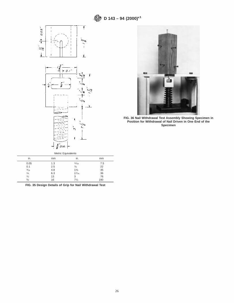
18.2 Preparation of Specimens—Nails shall be driven atright angles to the face of the specimen to a total penetration of11⁄4 in. (32 mm). Two nails shall be driven on a tangentialsurface, two on a radial surface, and one on each end. Thechoice between the two radial and two tangential surfaces shallbe such as to give a fair average of the piece. On radial andtangential faces, the nails shall be driven a sufficient distancefrom the edges and ends of the specimen to avoid splitting. Ingeneral, nails should not be driven closer than3⁄4 in. (19 mm)from the edge or 11⁄2 in. (38 mm) from the end of a piece. Thetwo nails on a radial or tangential face should not be driven inline with each other or less than 2 in. (50 mm) apart.
18.3 Procedure—Withdraw all six nails in a single speci-men immediately after driving. Fasten the specimens duringthe test in grips as shown in Figs. 35 and 36. Observe themaximum load only (Note 16).
FIG. 17 Compression-Perpendicular-to-Grain Test AssemblyShowing Method of Load Application and Measurement ofDeformation by Means of Averaging-Type Compressometer
D 143 – 94 (2000)e1
13
NOTE 17—See Fig. 37 for sample nail-withdrawal test data sheet form.
18.4 Speed of Testing—The load shall be applied continu-ously throughout the test at a rate of motion of the movablecrosshead of 0.075 in. (2 mm)/min (see 22.3).
18.5 Weight and Moisture Content—The specimen shall beweighed immediately before driving the nails. After the test, amoisture section approximately 1 in. (25 mm) in length shall becut from specimen (see 21.1 and 22.1).
19. Specific Gravity and Shrinkage in Volume (Note 17)
NOTE 18—Other methods of determining specific gravity using speci-mens of different shape, size, and moisture content are found in TestMethods D 2395.
19.1 Size of Specimens—The specific gravity and shrinkagein volume tests shall be made on green 2 by 2 by 6 in. (50 by50 by 150 mm) specimens. The actual cross-sectional dimen-sions and length shall be measured (see 22.2).
19.2 Procedure:19.2.1 Obtain both specific gravity and shrinkage-in-
volume determinations on the same specimen. Make thesedeterminations at approximately 12 % moisture content and atthe oven-dry condition (Test Methods D 2395).
19.2.2 A carbon impression of the end of the green speci-men may be made on the back of the data sheet (Note 18). Inlike manner, a carbon impression of the same end may be madeafter the specimen has been conditioned.
FIG. 18 Sample Data Sheet for Compression-Perpendicular-to-Grain Test
D 143 – 94 (2000)e1
14
NOTE 19—See Fig. 38 for a sample data and computation sheet for thespecific gravity and shrinkage-in-volume test.
19.2.3 Weigh the specimen when green (see 22.1) anddetermine the volume by the immersion method in accordancewith the procedures of Test Methods D 2395.
19.2.4 Open-pile the green specimens after immersion andallow them to air-season under room conditionss to a uniformmoisture content of approximately 12 %. The specimensshould then be weighed and the volume determined by theimmersion method.
19.2.5 Then, open-pile the specimens used for specificgravity and shrinkage determinations at 12 % moisture content,or duplicate specimens on which green weight and volumemeasurements have been made prior to conditioning to ap-proximately 12 % moisture content in an oven. Dry at 10362°C until approximately constant mass is reached (Test Meth-ods D 4442).
19.2.6 After oven-drying, weigh the specimens (see 22.1)and while still warm, immerse them in a hot paraffin bath,taking care to remove them quickly to ensure a thin coating.
19.2.7 Determine the volume of the paraffin-coated speci-men by immersion as before.
19.2.8 Fig. 39 illustrates the apparatus used in determiningthe specific gravity and shrinkage in volume. The use of anautomatic balance will facilitate increased rapidity and accu-racy of measurements.
20. Radial and Tangential Shrinkage
20.1 Size of Specimens—The radial and tangential shrink-age determinations shall be made on green 1 by 4 by 1 in. (25by 100 by 25 mm) specimens cut from 1 by 4-in. (25 by100-mm) boards, edge grain and flat grain, respectively.
20.2 Initial Measurement—The length of all specimensshall be measured.
20.3 Weight—The specimen shall be weighed when greenand after subsequent oven-drying (see 21.1).
20.4 Drying:
20.4.1 The green specimens shall be open-piled and allowedto air-season under room conditions to a uniform moisturecontent of approximately 12 %.
20.4.2 After weighing and measuring, the specimens shallthen be open-piled in an oven and dried at 1036 2°C untilapproximately constant mass is attained (Test MethodsD 4442).
20.5 Final Measurement—Measurements of mass andlength shall be made on the oven-dry specimens (see Note 18).
NOTE 20—See Fig. 40 for a sample data and computation sheet for theradial and tangential-shrinkage test.
20.6 Method of Measurement—Fig. 41 illustrates themethod of making the radial and tangential shrinkage measure-ments. An ordinary micrometer of required accuracy is suitablefor this work (see 22.2).
21. Moisture Determination
21.1 Selection—The sample for moisture determinations ofeach test specimen shall be selected as described for each test.
21.2 Weighing—Immediately after obtaining the moisturesample, all loose splinters shall be removed and the sampleshall be weighed (see 22.1).
21.3 Drying—The moisture samples shall be open-piled inan oven and dried at a temperature of 1036 2°C untilapproximately constant mass is attained, after which theoven-dry mass shall be determined.
21.4 Moisture Content—The loss in mass, expressed inpercent of the oven-dry mass as determined, shall be consid-ered the moisture content of the specimen.
22. Mass and Permissible Variations
22.1 Mass—The mass of test specimens and of moisturesamples shall be determined to an accuracy of not less than0.2 %.
22.2 Measurements—Measurements of test specimens shallbe made to an accuracy of not less than 0.3 %, except that in nocase shall the measurements be made to less than 0.01 in. (0.25mm). However, measurements of radial and tangential shrink-age specimens shall be made to the nearest 0.001 in. (0.02mm).
22.3 Testing Machine Speeds—The testing machine speedused should not vary by more than 25 % from that specified fora given test. If the specified speed cannot be obtained, thespeed used shall be recorded on the data sheet. The crossheadspeed shall mean the free-running or no-load speed of cross-head for testing machines of the mechanical drive type and theloaded crosshead speed for testing machines of the hydraulicloading type.
23. Calibration
23.1 All apparatus used in obtaining data shall be calibratedat sufficiently frequent intervals to ensure accuracy (PracticesE 4).
24. Precision and Bias
24.1 Statements of precision and bias for the tests have notyet been developed.
FIG. 19 Diagrammatic Sketch of Method of Conducting HardnessTest
D 143 – 94 (2000)e1
15
25. Keywords
25.1 clear specimens; small clear specimens; timber; wood
FIG. 20 Sample Data and Computation Sheet for Hardness Test
Metric Equivalentsin. 3⁄4 2 21⁄2mm 20 50 63
FIG. 21 Shear-Parallel-to-Grain Test Specimen
D 143 – 94 (2000)e1
16
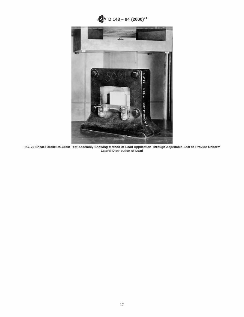
FIG. 22 Shear-Parallel-to-Grain Test Assembly Showing Method of Load Application Through Adjustable Seat to Provide UniformLateral Distribution of Load
D 143 – 94 (2000)e1
17
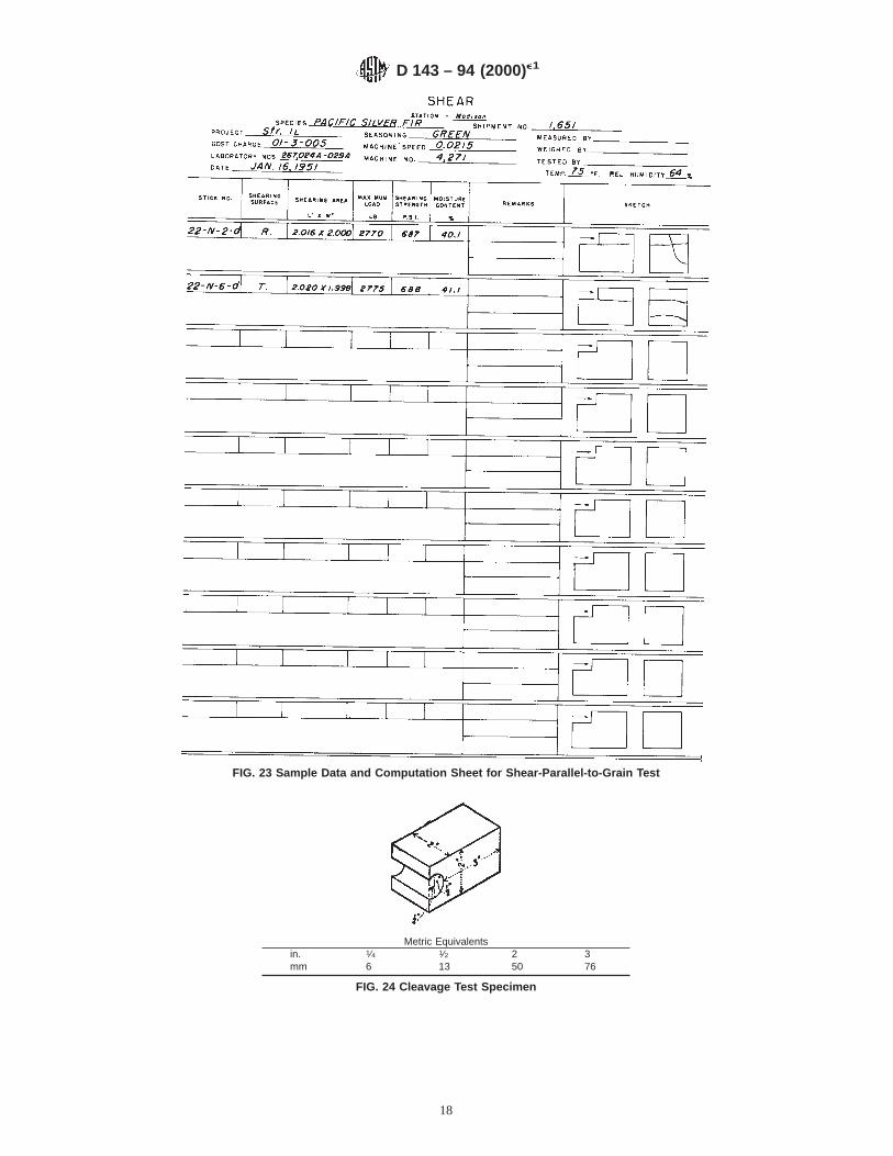
FIG. 23 Sample Data and Computation Sheet for Shear-Parallel-to-Grain Test
Metric Equivalentsin. 1⁄4 1⁄2 2 3mm 6 13 50 76
FIG. 24 Cleavage Test Specimen
D 143 – 94 (2000)e1
18
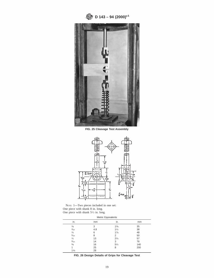
FIG. 25 Cleavage Test Assembly
NOTE 1—Two pieces included in one set:One piece with shank 8 in. long.One piece with shank 51⁄2 in. long.
Metric Equivalents
in. mm in. mm
1⁄8 3 13⁄8 353⁄16 4.8 11⁄2 381⁄4 6 17⁄8 485⁄16 8 2 501⁄2 13 21⁄4 579⁄16 14 3 765⁄8 16 51⁄2 1401 25 8 20011⁄8 28
FIG. 26 Design Details of Grips for Cleavage Test
D 143 – 94 (2000)e1
19

FIG. 27 Sample Data and Computation Sheet for Cleavage Test
D 143 – 94 (2000)e1
20

Metric Equivalentsin. 3⁄16 1⁄4 3⁄8 1 21⁄2 33⁄4 4 171⁄2 18mm 4.8 6.3 9.5 25 63 95 100 444 460
FIG. 28 Tension-Parallel-to-Grain Test Specimen
D 143 – 94 (2000)e1
21
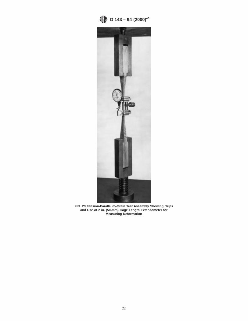
FIG. 29 Tension-Parallel-to-Grain Test Assembly Showing Gripsand Use of 2 in. (50-mm) Gage Length Extensometer for
Measuring Deformation
D 143 – 94 (2000)e1
22
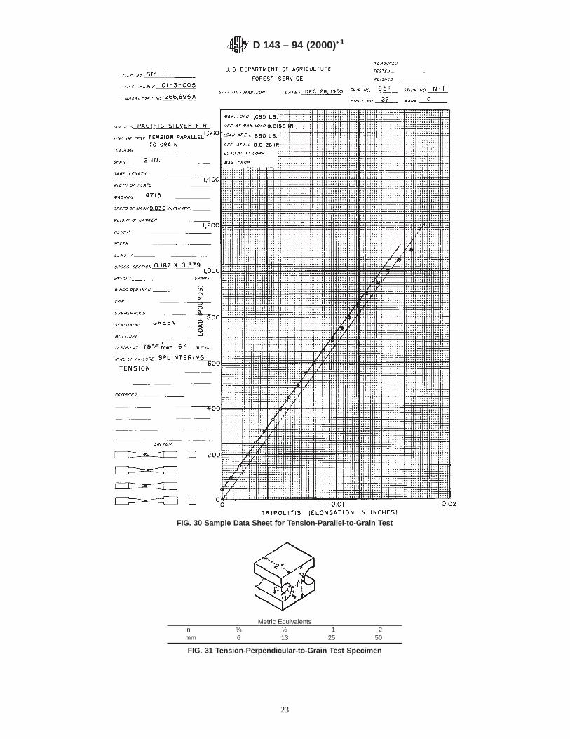
FIG. 30 Sample Data Sheet for Tension-Parallel-to-Grain Test
Metric Equivalentsin 1⁄4 1⁄2 1 2mm 6 13 25 50
FIG. 31 Tension-Perpendicular-to-Grain Test Specimen
D 143 – 94 (2000)e1
23

FIG. 32 Tension-Perpendicular-to-Grain Test Assembly
NOTE 1—Two pieces included in one set:One marked A.One marked B.Scale-Full Size
Metric Equivalents
in. mm in. mm
1⁄16 1.6 2 501⁄8 3.2 21⁄4 571⁄2 13 25⁄8 675⁄8 16 3 767⁄8 22 41⁄2 1141 25 51⁄2 14011⁄8 29 71⁄2 19011⁄2 38
FIG. 33 Design Details of Grips for Tension-Perpendicular-to-Grain Test
D 143 – 94 (2000)e1
24
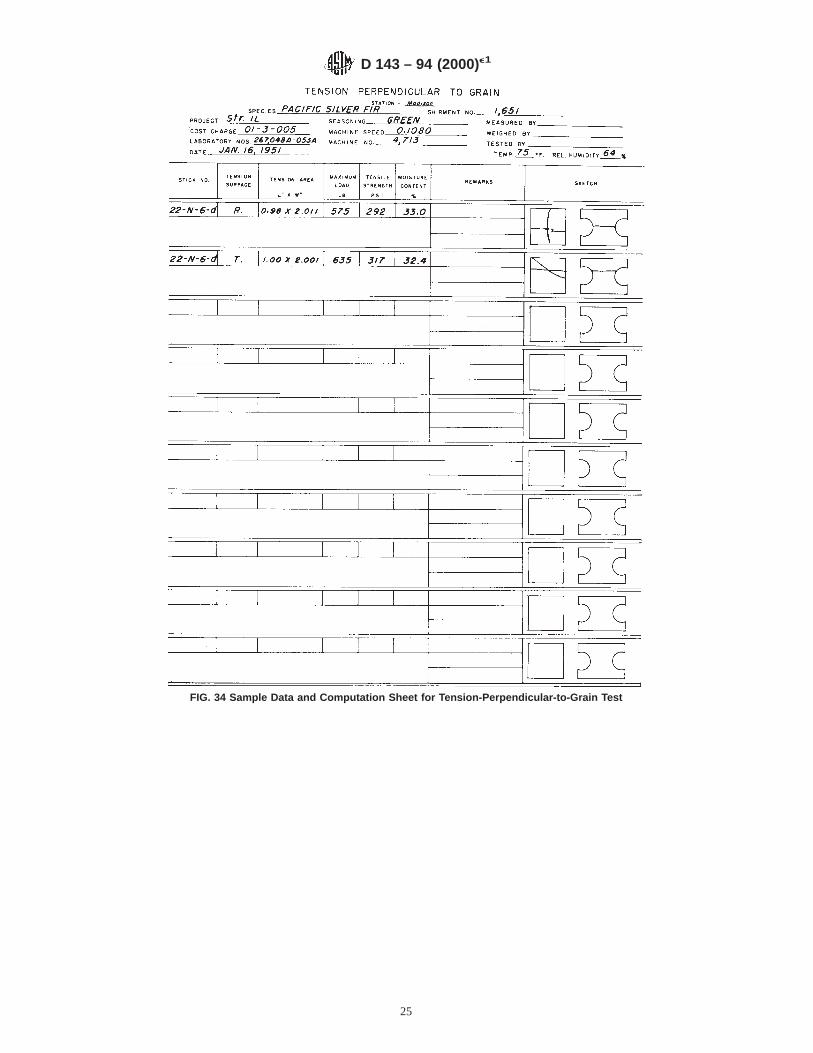
FIG. 34 Sample Data and Computation Sheet for Tension-Perpendicular-to-Grain Test
D 143 – 94 (2000)e1
25
Metric Equivalents
in. mm in. mm
0.05 1.3 11⁄16 7.50.1 2.5 7⁄8 223⁄16 4.8 13⁄8 351⁄4 6.3 17⁄16 361⁄2 13 3 765⁄8 16 71⁄2 190
FIG. 35 Design Details of Grip for Nail Withdrawal Test
FIG. 36 Nail Withdrawal Test Assembly Showing Specimen inPosition for Withdrawal of Nail Driven in One End of the
Specimen
D 143 – 94 (2000)e1
26
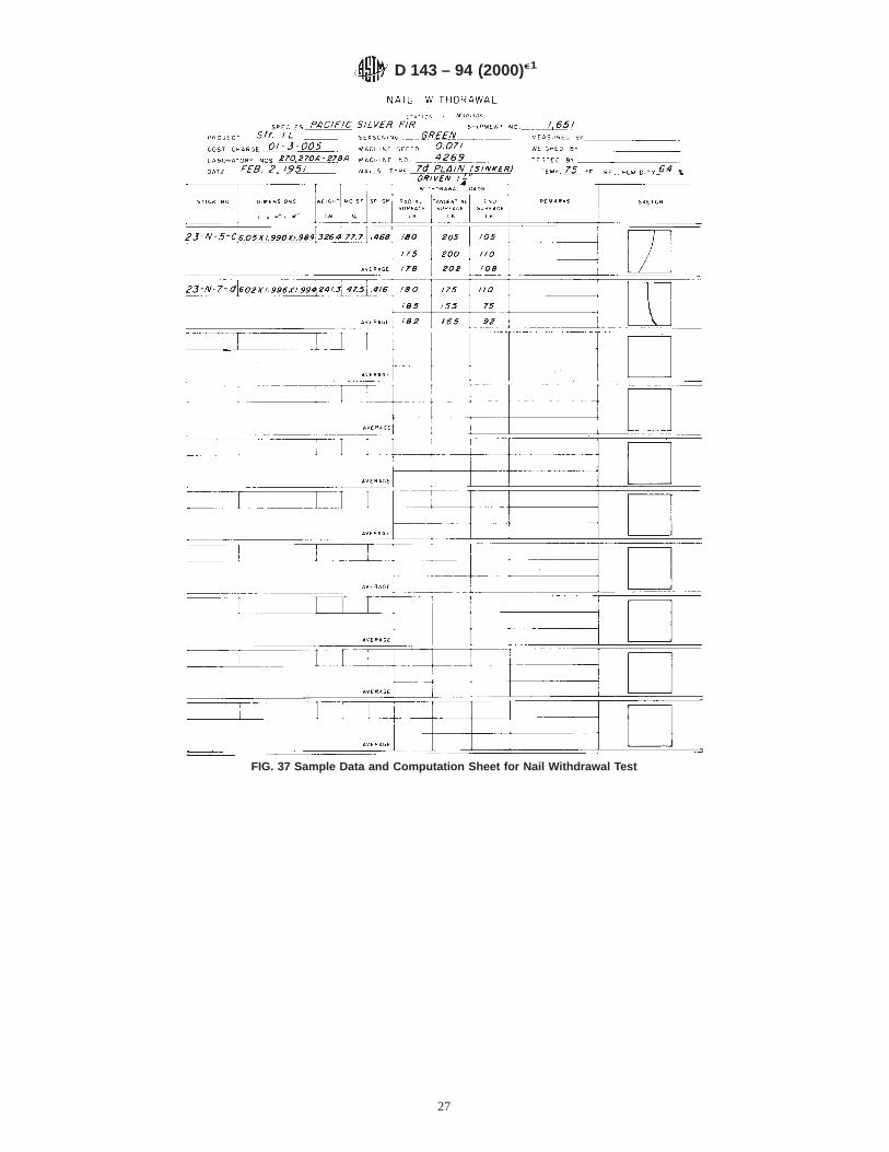
FIG. 37 Sample Data and Computation Sheet for Nail Withdrawal Test
D 143 – 94 (2000)e1
27
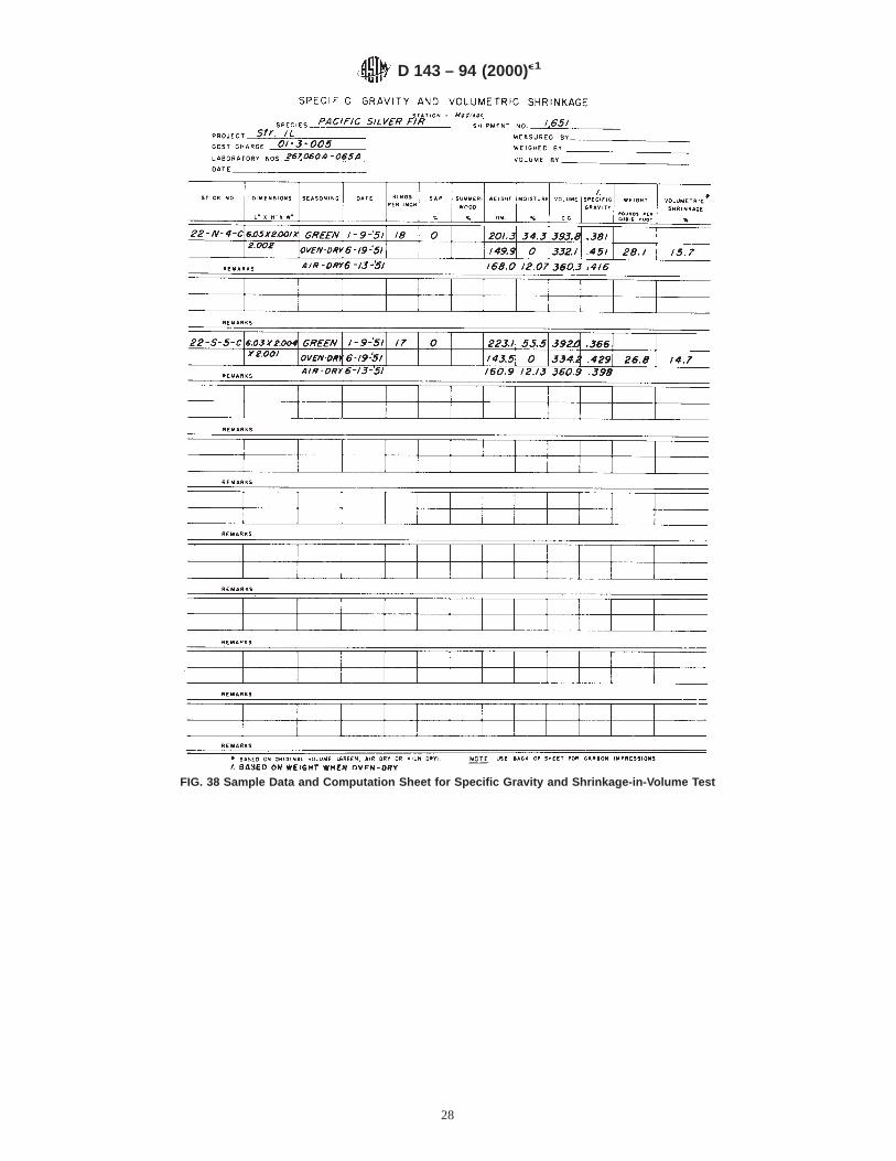
FIG. 38 Sample Data and Computation Sheet for Specific Gravity and Shrinkage-in-Volume Test
D 143 – 94 (2000)e1
28

FIG. 39 Specific Gravity and Shrinkage-in-Volume Test Set-Up
D 143 – 94 (2000)e1
29
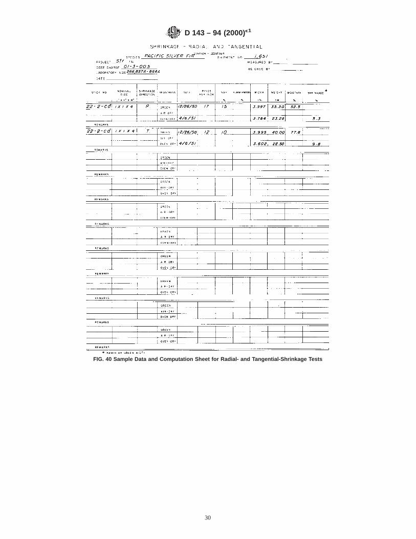
FIG. 40 Sample Data and Computation Sheet for Radial- and Tangential-Shrinkage Tests
D 143 – 94 (2000)e1
30

ASTM International takes no position respecting the validity of any patent rights asserted in connection with any item mentionedin this standard. Users of this standard are expressly advised that determination of the validity of any such patent rights, and the riskof infringement of such rights, are entirely their own responsibility.
This standard is subject to revision at any time by the responsible technical committee and must be reviewed every five years andif not revised, either reapproved or withdrawn. Your comments are invited either for revision of this standard or for additional standardsand should be addressed to ASTM International Headquarters. Your comments will receive careful consideration at a meeting of theresponsible technical committee, which you may attend. If you feel that your comments have not received a fair hearing you shouldmake your views known to the ASTM Committee on Standards, at the address shown below.
This standard is copyrighted by ASTM International, 100 Barr Harbor Drive, PO Box C700, West Conshohocken, PA 19428-2959,United States. Individual reprints (single or multiple copies) of this standard may be obtained by contacting ASTM at the aboveaddress or at 610-832-9585 (phone), 610-832-9555 (fax), or [email protected] (e-mail); or through the ASTM website(www.astm.org).
FIG. 41 Radial- and Tangential-Shrinkage Test Assembly
D 143 – 94 (2000)e1
31