Embed Size (px)
Citation preview
Monmouthshire County Council
Building control guidance document
Domestic Extensions
Building Regulations 2010 (with 2013 amendments) For use in Wales
May 2013 Edition
Guidance produced for Monmouthshire County Council Building Control by Anthony Gwynne of Forest of Dean District Council
2
Contents:
Part A: Structure
Part B: Fire safety and means of escape
Part C: Site preparation and resistance to contaminates and moisture
Part D: Toxic substances
Part E: Resistance to passage of sound
Part F: Ventilation
Part G: Sanitation, hot water safety and water efficiency
Part H: Drainage and waste disposal
Part J: Combustion appliances and fuel storage systems
Part K: Protection from falling, collision and impact (inc
glazing) Part L: Conservation of fuel and power (Existing
dwellings)
Part M: Access and use of buildings (For disabled
persons) Part P: Electrical safety (Dwellings)
Materials and Workmanship
Acknowledgements for contributions to the guidance document
About the author
Guidance notes copyright
3
Part A: Structure Please refer fully to Approved Document A: Structure (2004 edition with 2010 amendments)
Contents A1: Substructure Foundations
(i) Site mixed concrete (Standardised Prescribed mix ST) (ii) Ready mixed concrete (Designated mix GEN, RC and FND) (iii) Hand mixed concrete Guidance Table 1: Concrete mixes for foundations
Foundation types Strip foundations Guidance Diagram 1: Strip foundation section detail Trench fill foundations Guidance Diagram 2: Trench fill foundation section detail Guidance Diagram 3: Stepped foundation section detail Guidance Diagram 4: Foundation projections to piers, buttresses and chimneys Guidance Table 2: Minimum width of strip/trench fill foundations Guidance Table 3: Minimum depth of strip/trench fill foundations
Building near trees, hedges, shrubs or in clay sub soils Guidance Diagram 5: Heave precautions for trench fill foundations with suspended beam and block floors in shrinkable clay sub soils Guidance Table 4: Minimum void dimensions and clay heave protection for foundations and suspended beam and block floors Guidance Diagram 5.1: Heave precautions for trench fill foundations with suspended cast in-situ reinforced concrete floor in shrinkable clay sub soils Guidance Table 4.1: Minimum void dimensions and clay heave protection for foundations and suspended in-situ reinforced concrete floors and beams
Alternative foundation designs Raft foundations Guidance Diagram 6: Raft foundation section detail Piled foundations
Retaining walls and basements Guidance Diagram 7: Basement section detail Basements and tanking systems
Ground floors and sub structure walls Sub structure walls
Guidance Diagram 8: Walls supporting differences in ground levels Ground floors
Ground bearing solid concrete floors Guidance Diagram 9: Typical section through a ground bearing solid concrete floor and foundation Guidance Table 5: Examples of insulation for ground bearing floor slabs Suspended reinforced in-situ concrete ground floor slab supported on internal walls. Guidance Diagram 10: Typical section through a suspended reinforced in-situ concrete ground floor slab supported on internal walls. Suspended beam and block ground floors Guidance Diagram 11: Typical section through a suspended beam and block ground floor Guidance Table 6: Examples of insulation for suspended beam and block ground floors. Proprietary under floor heating systems Floating floors
Guidance Table 7: Examples of insulation for floating floors Suspended timber ground floor Guidance Diagram 12: Typical section through a suspended timber ground floor Guidance Table 8: Examples of insulation for suspended timber ground floors Garage ground bearing concrete floor Guidance Diagram 13: Typical section through a ground bearing garage floor and foundation
A2: Superstructure Minimum headroom heights Maximum height of residential buildings up to 3 storeys Maximum storey heights Maximum wall lengths
4
Guidance Diagram 14: Measuring wall lengths (plan detail not to scale) Vertical lateral restraint to walls Minimum thickness of external walls, compartment walls and separating walls constructed of coursed brick or block work. Guidance Table 9: Minimum thickness of certain external walls, compartment walls and separating walls constructed of coursed brick or block work. Minimum thickness of internal load-bearing walls Buttressing wall design Pier and chimney design providing restraint: Buttressing, sizes of openings and recesses in cavity walls Guidance Table 10: Compressive strength of masonry units
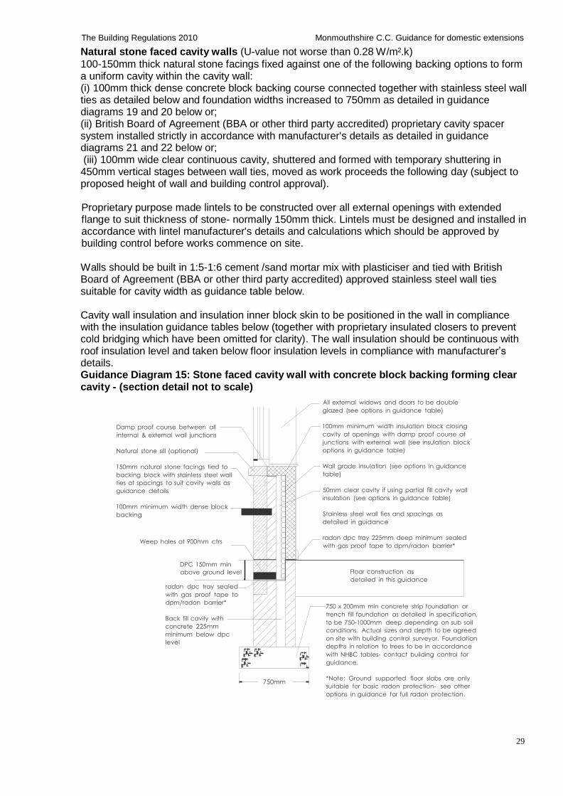
External cavity wall construction Cavity wall construction Natural stone faced cavity walls Guidance Diagram 15: Stone faced cavity wall with concrete block backing forming clear cavity Guidance Diagram 16: Stone faced cavity wall with concrete block backing forming clear cavity Guidance Diagram 17: Stone faced cavity wall with cavity wall spacer system or shuttered cavity Guidance Diagram 18: Stone faced cavity wall with cavity wall spacer system or shuttered cavity Guidance Table 11: Cavity wall tie spacing Guidance Table 12: Examples of partial cavity fill insulation for external cavity walls Guidance Table 13: Examples of partial cavity fill insulation for external cavity walls Guidance Table 14: Examples of full cavity fill insulation for external cavity walls Guidance Table 15: Examples of full cavity fill insulation for external cavity walls Walls between heated and un heated areas Guidance Table 16: Examples of insulation for solid walls between heated and un-heated areas External timber framed walls with separate brick or block finish Guidance Table 17: : Examples of insulation for cavity walls with internal timber frame: Guidance Diagram 19: Typical section through external timber framed walls with separate external brick or block wall and cavity External timber framed walls with render finish Guidance Diagram 20: Typical section through external timber framed walls with painted render finish External timber framed walls with cladding Guidance Diagram 21: Typical section through external timber framed walls with Upvc/timber weather board finish Guidance Table 18: Examples of insulation for timber frame walls with external tile/render/cladding finishes:
Detached garage (or similar single storey building) with SINGLE SKIN external walls Guidance Diagram 22: Design criteria for small detached single storey garages or similar
Wall abutments Lintels and weep holes Structural columns/beams etc Movement joints Guidance Table 19: Movement joint widths and spacing in walls Cavity closers Lateral restraint strapping of upper floors to walls
(i) Strapping of floor joists parallel to walls Guidance Diagram 23: Strapping of floor joists parallel to walls (ii) Strapping of floor joists at right angles to walls Guidance Diagram 24: Strapping of floor joists at right angles to walls
Lateral restraint strapping of roofs to walls Strapping of roofs to gable end walls Guidance Diagram 25: Strapping of roofs to gable end walls Strapping of wall plates and roofs at eaves level Guidance Diagram 26: Strapping of wall plates and roofs at eaves level Lateral restraint strapping of walls at ceiling level
A3: Separating walls and floors Masonry party walls separating dwellings Guidance Diagram 27: Section detail of masonry separating wall as Wall type 2.1 of ADE Double leaf timber frame party walls separating dwellings Guidance Diagram 28: Plan detail of timber stud separating wall as Wall type 4.1 (new buildings) of ADE Upgrading sound insulation of existing party walls separating dwellings
5
Guidance Diagram 29: Plan of upgrading masonry separating wall as Wall type 4.2 (material change of use) of ADE Party floors separating buildings Sound testing requirements
A4: Internal partitions Internal load bearing masonry partitions Internal load bearing timber stud partitions Internal masonry non-load bearing partitions Internal timber studwork non-load bearing partitions
A5: Intermediate upper floor(s) Floor Joists Guidance Table 20: Timber sizes and spans for domestic floor joists (Strength Class C24) Trimming and trimmer joists Guidance Table 21: Timber sizes and spans for trimmer joist supporting trimmed joists (Strength Class C24) Guidance Table 22: Timber sizes and spans for trimming joist supporting trimmer joist (Strength Class C24) Guidance Diagram 30: Typical plan layout of opening formed in suspended timber floor(s) using trimming, trimmer and trimmed joists. Notching and drilling of structural timbers
Sound insulation to floors within the dwelling Soil and vent pipe (SVP) boxing internally Exposed intermediate upper floors Guidance Diagram 31: Typical section through an upper floor Guidance Table 23: Examples of insulation for exposed upper floors
A6: Pitched roofs Pitched roof coverings Pitched roof structure (i) Roof trusses (including attic and girder trusses) (ii) Cut roof construction Notching and drilling of structural timbers Guidance Diagram 32: Typical section through pitched roof with ceiling joists at wall plate level Guidance Diagram 33: Typical section through a pitched roof with purlins and high collars Guidance Table 24: Timber sizes and permissible clear spans for single span common jack rafters at 400mm spacing (Strength Class C24) Guidance Table 25: Timber sizes and permissible clear spans for purlins (Strength Class C24) Guidance Table 26: Timber size and permissible clear spans for ceiling joists at 400mm spacing (Strength Class C24) Guidance Table 27: Timber sizes and permissible clear spans for ceiling binders (Strength Class C24) Roof restraint Roof insulation and ventilation gaps Guidance Table 28: Examples of roof insulation fixed between/under rafters. Guidance Table 29: Examples of roof insulation laid horizontally between and over ceiling joists Guidance Table 30: Examples of roof insulation fixed over/between rafters Guidance Diagram 34: Typical section through a dormer roof (not to scale) Guidance Diagram 35: Typical roof valley detail Guidance Diagram 36: Typical lean too roof abutment with cavity wall detail Pitched roof ventilation requirements when using a non breathable roof membrane (i) Duo pitched roof with horizontal ceilings and insulation at ceiling level (ii) Mono pitched roofs with horizontal ceilings and insulation at ceiling level (iii) Duo pitched roof with insulation following slope of rafters (rooms in the roof) Proprietary vapour permeable roof membrane Valleys and lead work Lofts hatches, doors and Light wells to roof spaces
A7: Flat roof construction 4 options as follows: Option 1. Flat roof with 'cold deck' Flat roofs with unlimited access/habitable use Guidance Diagram 37: Typical section through a flat roof with 'cold deck' Guidance Table 31: Examples of 'cold roof' insulation fixed between/under flat roof joists Option 2. Flat roof with 'warm deck'

6
Flat roofs with unlimited access/habitable use Guidance Diagram 38: Typical section through a flat roof with 'warm deck' Guidance Table 32: Examples of 'warm roof' insulation fixed above flat roof joists Option 3. Flat roof with inverted 'warm deck' (insulation on top of waterproof coverings) Option 4. Flat roof with green roof on 'warm deck' (Either intensive or extensive) Intensive green roof Extensive green roof The design, workmanship and selection of materials for flat roofs Cavity closers Guidance Table 33: Timber sizes and permissible clear spans for joists for flat roofs - with access and use for maintenance and repairs only (Strength Class C24) Guidance Table 34: Timber sizes and permissible clear spans for joists for flat roofs - with unlimited access (Strength Class C24)
A8: Mortars, renders and gypsum plasters Cement mortars and renders Guidance Table 35: Cement mortar - general mix ratio Guidance Table 36: Cement render - general mix ratio Guidance Table 37: Thickness of render coats Gypsum plasters Guidance Table 38: Gypsum plaster for internal finishes - general mix ratio
7
Foundations
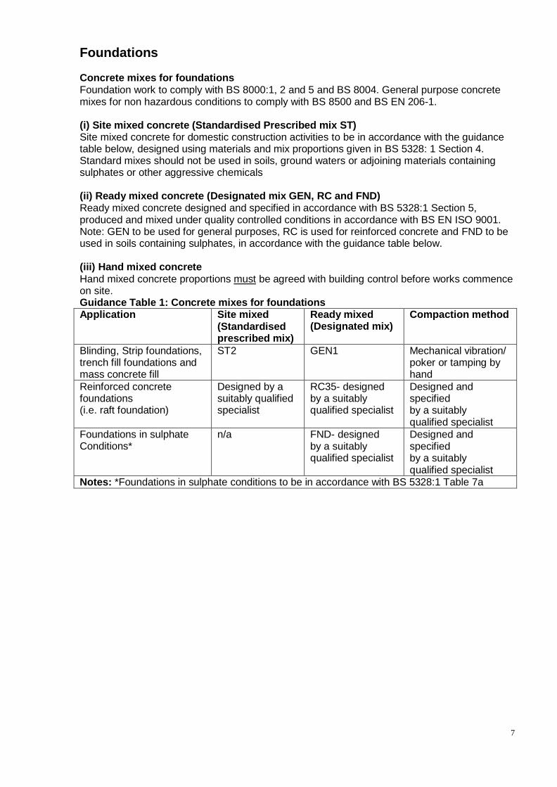
Concrete mixes for foundations Foundation work to comply with BS 8000:1, 2 and 5 and BS 8004. General purpose concrete mixes for non hazardous conditions to comply with BS 8500 and BS EN 206-1.
(i) Site mixed concrete (Standardised Prescribed mix ST) Site mixed concrete for domestic construction activities to be in accordance with the guidance table below, designed using materials and mix proportions given in BS 5328: 1 Section 4. Standard mixes should not be used in soils, ground waters or adjoining materials containing sulphates or other aggressive chemicals
(ii) Ready mixed concrete (Designated mix GEN, RC and FND) Ready mixed concrete designed and specified in accordance with BS 5328:1 Section 5, produced and mixed under quality controlled conditions in accordance with BS EN ISO 9001. Note: GEN to be used for general purposes, RC is used for reinforced concrete and FND to be used in soils containing sulphates, in accordance with the guidance table below.
(iii) Hand mixed concrete
Hand mixed concrete proportions must be agreed with building control before works commence on site. Guidance Table 1: Concrete mixes for foundations Application Site mixed
(Standardised prescribed mix)
Ready mixed (Designated mix)
Compaction method
Blinding, Strip foundations, trench fill foundations and mass concrete fill
ST2 GEN1 Mechanical vibration/ poker or tamping by hand
Reinforced concrete foundations (i.e. raft foundation)
Designed by a suitably qualified specialist
RC35- designed by a suitably qualified specialist
Designed and specified by a suitably qualified specialist
Foundations in sulphate Conditions*
n/a FND- designed by a suitably qualified specialist
Designed and specified by a suitably qualified specialist
Notes: *Foundations in sulphate conditions to be in accordance with BS 5328:1 Table 7a
8
The Building Regulations 2010 Monmouthshire C.C. Guidance for domestic extensions
Foundation types Strip foundations
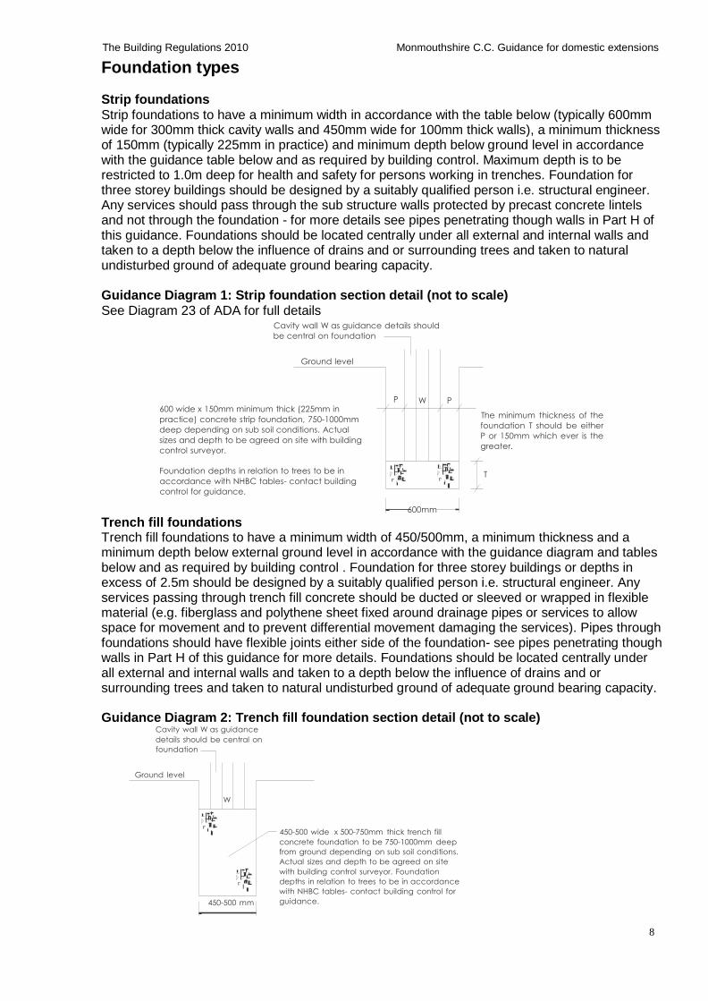
Strip foundations to have a minimum width in accordance with the table below (typically 600mm wide for 300mm thick cavity walls and 450mm wide for 100mm thick walls), a minimum thickness of 150mm (typically 225mm in practice) and minimum depth below ground level in accordance with the guidance table below and as required by building control. Maximum depth is to be restricted to 1.0m deep for health and safety for persons working in trenches. Foundation for three storey buildings should be designed by a suitably qualified person i.e. structural engineer. Any services should pass through the sub structure walls protected by precast concrete lintels and not through the foundation - for more details see pipes penetrating though walls in Part H of this guidance. Foundations should be located centrally under all external and internal walls and taken to a depth below the influence of drains and or surrounding trees and taken to natural undisturbed ground of adequate ground bearing capacity.
Guidance Diagram 1: Strip foundation section detail (not to scale)
See Diagram 23 of ADA for full details Cavity wall W as guidance details should
be central on foundation
Ground level
600 wide x 150mm minimum thick (225mm in
practice) concrete strip foundation, 750-1000mm
deep depending on sub soil conditions. Actual
sizes and depth to be agreed on site with building
control surveyor.
Foundation depths in relation to trees to be in
accordance with NHBC tables- contact building
control for guidance.
P W P
The minimum thickness of the
foundation T should be either
P or 150mm which ever is the
greater.
T
Trench fill foundations
600mm
Trench fill foundations to have a minimum width of 450/500mm, a minimum thickness and a minimum depth below external ground level in accordance with the guidance diagram and tables below and as required by building control . Foundation for three storey buildings or depths in excess of 2.5m should be designed by a suitably qualified person i.e. structural engineer. Any services passing through trench fill concrete should be ducted or sleeved or wrapped in flexible material (e.g. fiberglass and polythene sheet fixed around drainage pipes or services to allow space for movement and to prevent differential movement damaging the services). Pipes through foundations should have flexible joints either side of the foundation- see pipes penetrating though walls in Part H of this guidance for more details. Foundations should be located centrally under all external and internal walls and taken to a depth below the influence of drains and or surrounding trees and taken to natural undisturbed ground of adequate ground bearing capacity.
Guidance Diagram 2: Trench fill foundation section detail (not to scale)
Cavity wall W as guidance
details should be central on
foundation
Ground level
W
450-500 mm
450-500 wide x 500-750mm thick trench fill
concrete foundation to be 750-1000mm deep
from ground depending on sub soil conditions.
Actual sizes and depth to be agreed on site
with building control surveyor. Foundation
depths in relation to trees to be in accordance
with NHBC tables- contact building control for
guidance.
9
The Building Regulations 2010 Monmouthshire C.C. Guidance for domestic extensions
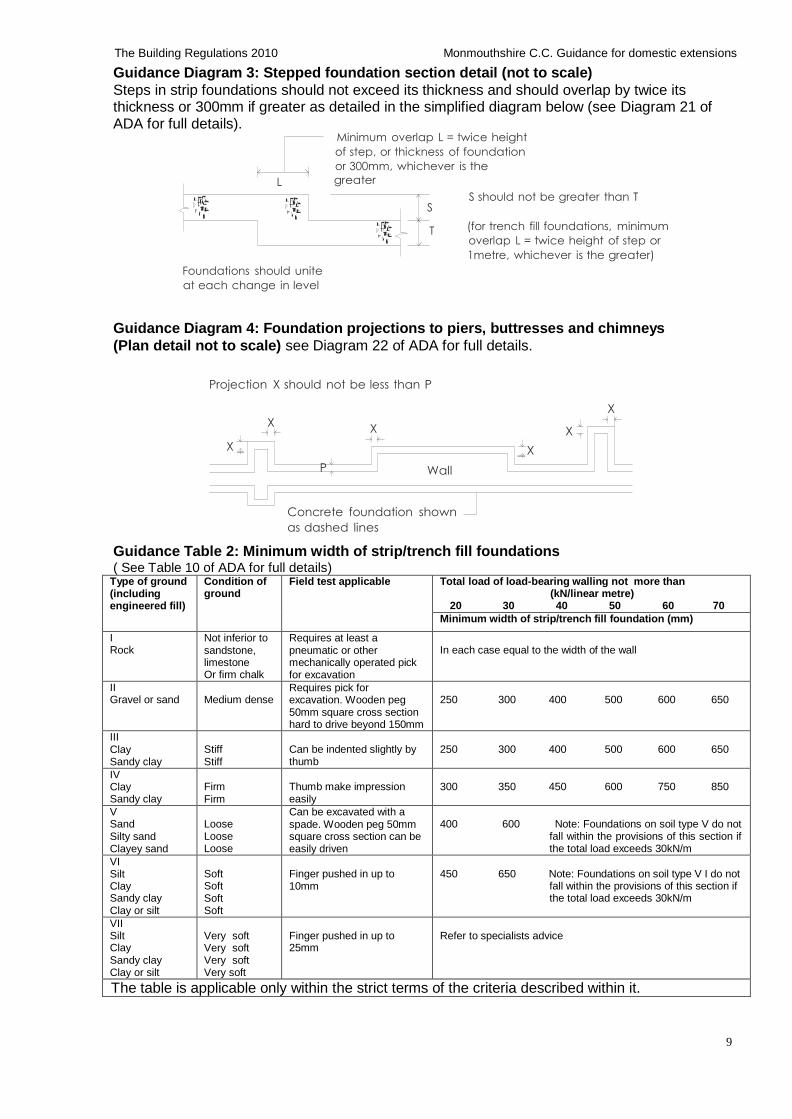
Guidance Diagram 3: Stepped foundation section detail (not to scale)
Steps in strip foundations should not exceed its thickness and should overlap by twice its thickness or 300mm if greater as detailed in the simplified diagram below (see Diagram 21 of ADA for full details).
Minimum overlap L = twice height
of step, or thickness of foundation
or 300mm, whichever is the
L greater
Foundations should unite
at each change in level
S should not be greater than T S
T (for trench fill foundations, minimum
overlap L = twice height of step or
1metre, whichever is the greater)
Guidance Diagram 4: Foundation projections to piers, buttresses and chimneys
(Plan detail not to scale) see Diagram 22 of ADA for full details.
Projection X should not be less than P
X X
X X
X X
P Wall
Concrete foundation shown
as dashed lines
Guidance Table 2: Minimum width of strip/trench fill foundations ( See Table 10 of ADA for full details)
Type of ground (including engineered fill)
Condition of ground
Field test applicable Total load of load-bearing walling not more than (kN/linear metre)
20 30 40 50 60 70
Minimum width of strip/trench fill foundation (mm)
I Rock
Not inferior to sandstone, limestone Or firm chalk
Requires at least a pneumatic or other mechanically operated pick for excavation
In each case equal to the width of the wall
II Gravel or sand
Medium dense
Requires pick for excavation. Wooden peg 50mm square cross section hard to drive beyond 150mm
250 300 400 500 600 650
III Clay Sandy clay
Stiff Stiff
Can be indented slightly by thumb
250 300 400 500 600 650
IV Clay Sandy clay
Firm Firm
Thumb make impression easily
300 350 450 600 750 850
V Sand Silty sand Clayey sand
Loose Loose Loose
Can be excavated with a spade. Wooden peg 50mm square cross section can be easily driven
400 600 Note: Foundations on soil type V do not
fall within the provisions of this section if the total load exceeds 30kN/m
VI Silt Clay Sandy clay Clay or silt
Soft Soft Soft Soft
Finger pushed in up to 10mm
450 650 Note: Foundations on soil type V I do not
fall within the provisions of this section if the total load exceeds 30kN/m
VII Silt Clay Sandy clay Clay or silt
Very soft Very soft Very soft Very soft
Finger pushed in up to 25mm
Refer to specialists advice
The table is applicable only within the strict terms of the criteria described within it.
10
The Building Regulations 2010 Monmouthshire C.C. Guidance for domestic extensions
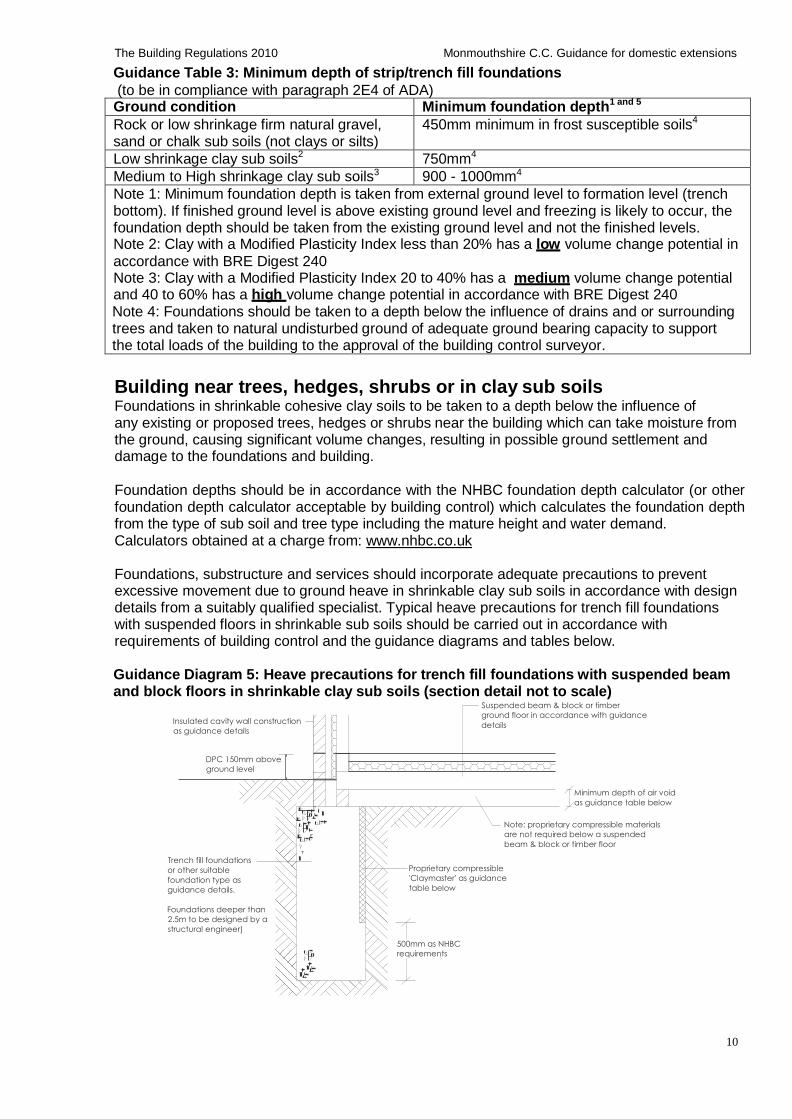
Guidance Table 3: Minimum depth of strip/trench fill foundations
(to be in compliance with paragraph 2E4 of ADA) Ground condition Minimum foundation depth1 and 5
Rock or low shrinkage firm natural gravel, sand or chalk sub soils (not clays or silts)
450mm minimum in frost susceptible soils4
Low shrinkage clay sub soils2 750mm4
Medium to High shrinkage clay sub soils3 900 - 1000mm4
Note 1: Minimum foundation depth is taken from external ground level to formation level (trench bottom). If finished ground level is above existing ground level and freezing is likely to occur, the foundation depth should be taken from the existing ground level and not the finished levels. Note 2: Clay with a Modified Plasticity Index less than 20% has a low volume change potential in
accordance with BRE Digest 240 Note 3: Clay with a Modified Plasticity Index 20 to 40% has a medium volume change potential and 40 to 60% has a high volume change potential in accordance with BRE Digest 240 Note 4: Foundations should be taken to a depth below the influence of drains and or surrounding trees and taken to natural undisturbed ground of adequate ground bearing capacity to support the total loads of the building to the approval of the building control surveyor.
Building near trees, hedges, shrubs or in clay sub soils Foundations in shrinkable cohesive clay soils to be taken to a depth below the influence of any existing or proposed trees, hedges or shrubs near the building which can take moisture from the ground, causing significant volume changes, resulting in possible ground settlement and damage to the foundations and building.
Foundation depths should be in accordance with the NHBC foundation depth calculator (or other foundation depth calculator acceptable by building control) which calculates the foundation depth from the type of sub soil and tree type including the mature height and water demand. Calculators obtained at a charge from: www.nhbc.co.uk
Foundations, substructure and services should incorporate adequate precautions to prevent excessive movement due to ground heave in shrinkable clay sub soils in accordance with design details from a suitably qualified specialist. Typical heave precautions for trench fill foundations with suspended floors in shrinkable sub soils should be carried out in accordance with requirements of building control and the guidance diagrams and tables below.
Guidance Diagram 5: Heave precautions for trench fill foundations with suspended beam and block floors in shrinkable clay sub soils (section detail not to scale)
Suspended beam & block or timber
ground floor in accordance with guidance Insulated cavity wall construction
as guidance details
DPC 150mm above
ground level
details
Minimum depth of air void
as guidance table below
Trench fill foundations
or other suitable
foundation type as
guidance details.
Foundations deeper than
2.5m to be designed by a
structural engineer)
Note: proprietary compressible materials
are not required below a suspended
beam & block or timber floor
Proprietary compressible
'Claymaster' as guidance
table below
500mm as NHBC
requirements
11
The Building Regulations 2010 Monmouthshire C.C. Guidance for domestic extensions
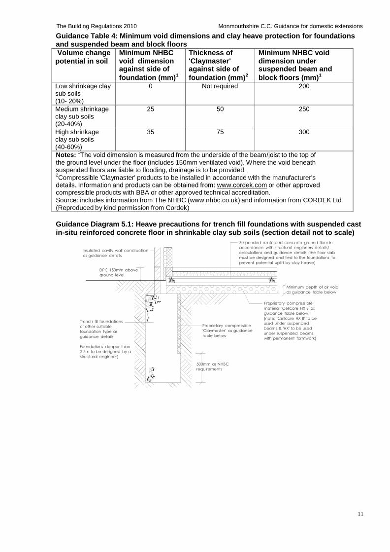
Guidance Table 4: Minimum void dimensions and clay heave protection for foundations and suspended beam and block floors
Volume change potential in soil
Minimum NHBC void dimension against side of
foundation (mm)1
Thickness of 'Claymaster' against side of
foundation (mm)2
Minimum NHBC void dimension under suspended beam and
block floors (mm)1
Low shrinkage clay sub soils (10- 20%)
0 Not required 200
Medium shrinkage clay sub soils (20-40%)
25 50 250
High shrinkage clay sub soils (40-60%)
35 75 300
Notes: 1The void dimension is measured from the underside of the beam/joist to the top of
the ground level under the floor (includes 150mm ventilated void). Where the void beneath suspended floors are liable to flooding, drainage is to be provided. 2Compressible 'Claymaster' products to be installed in accordance with the manufacturer's
details. Information and products can be obtained from: www.cordek.com or other approved compressible products with BBA or other approved technical accreditation. Source: includes information from The NHBC (www.nhbc.co.uk) and information from CORDEK Ltd (Reproduced by kind permission from Cordek)
Guidance Diagram 5.1: Heave precautions for trench fill foundations with suspended cast in-situ reinforced concrete floor in shrinkable clay sub soils (section detail not to scale)
Insulated cavity wall construction
as guidance details
DPC 150mm above
ground level
Suspended reinforced concrete ground floor in
accordance with structural engineers details/
calculations and guidance details (the floor slab
must be designed and tied to the foundations to
prevent potential uplift by clay heave)
Minimum depth of air void
as guidance table below
Trench fill foundations
or other suitable
foundation type as
guidance details.
Foundations deeper than
2.5m to be designed by a
structural engineer)
Proprietary compressible
'Claymaster' as guidance
table below
500mm as NHBC
requirements
Proprietary compressible
material 'Cellcore HX S' as
guidance table below.
(note: 'Cellcore HX B' to be
used under suspended
beams & 'HX' to be used
under suspended beams
with permanent formwork)
12
The Building Regulations 2010 Monmouthshire C.C. Guidance for domestic extensions
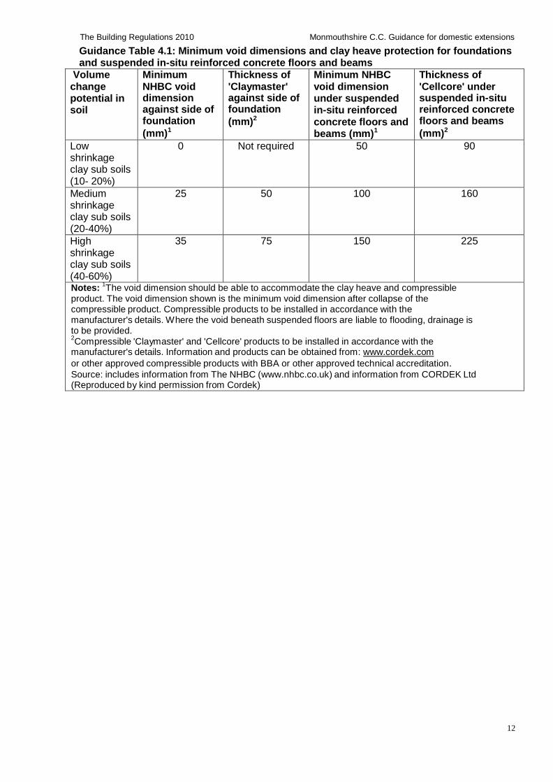
Guidance Table 4.1: Minimum void dimensions and clay heave protection for foundations and suspended in-situ reinforced concrete floors and beams
Volume change potential in soil
Minimum NHBC void dimension against side of foundation
(mm)1
Thickness of 'Claymaster' against side of foundation
(mm)2
Minimum NHBC void dimension under suspended in-situ reinforced concrete floors and beams (mm)1
Thickness of 'Cellcore' under suspended in-situ reinforced concrete floors and beams
(mm)2
Low shrinkage clay sub soils (10- 20%)
0 Not required 50 90
Medium shrinkage clay sub soils (20-40%)
25 50 100 160
High shrinkage clay sub soils (40-60%)
35 75 150 225
Notes: 1The void dimension should be able to accommodate the clay heave and compressible
product. The void dimension shown is the minimum void dimension after collapse of the compressible product. Compressible products to be installed in accordance with the manufacturer's details. Where the void beneath suspended floors are liable to flooding, drainage is to be provided. 2Compressible 'Claymaster' and 'Cellcore' products to be installed in accordance with the
manufacturer's details. Information and products can be obtained from: www.cordek.com
or other approved compressible products with BBA or other approved technical accreditation. Source: includes information from The NHBC (www.nhbc.co.uk) and information from CORDEK Ltd (Reproduced by kind permission from Cordek)
13
The Building Regulations 2010 Monmouthshire C.C. Guidance for domestic extensions
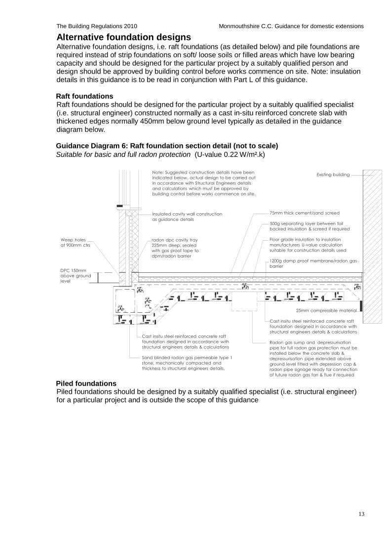
Alternative foundation designs Alternative foundation designs, i.e. raft foundations (as detailed below) and pile foundations are required instead of strip foundations on soft/ loose soils or filled areas which have low bearing capacity and should be designed for the particular project by a suitably qualified person and design should be approved by building control before works commence on site. Note: insulation details in this guidance is to be read in conjunction with Part L of this guidance.
Raft foundations Raft foundations should be designed for the particular project by a suitably qualified specialist (i.e. structural engineer) constructed normally as a cast in-situ reinforced concrete slab with thickened edges normally 450mm below ground level typically as detailed in the guidance diagram below.
Guidance Diagram 6: Raft foundation section detail (not to scale)
Suitable for basic and full radon protection (U-value 0.22 W/m².k)
Note: Suggested construction details have been
indicated below, actual design to be carried out
in accordance with Structural Engineers details
and calculations which must be approved by
building control before works commence on site.
Existing building
Insulated cavity wall construction
as guidance details
75mm thick cement/sand screed
500g separating layer between foil
backed insulation & screed if required
Weep holes
at 900mm ctrs
DPC 150mm
above ground
level
radon dpc cavity tray
225mm deep, sealed
with gas proof tape to
dpm/radon barrier
Floor grade insulation to insulation
manufacturers U-value calculation
suitable for construction details used
1200g damp proof membrane/radon gas
barrier
25mm compressible material
Piled foundations
Cast insitu steel reinforced concrete raft
foundation designed in accordance with
structural engineers details & calculations
Sand blinded radon gas permeable type 1
stone, mechanically compacted and
thickness to structural engineers details.
Cast insitu steel reinforced concrete raft
foundation designed in accordance with
structural engineers details & calculations
Radon gas sump and depressurisation
pipe for full radon gas protection must be
installed below the concrete slab &
depressurisation pipe extended above
ground level fitted with depression cap &
radon pipe signage ready for connection
of future radon gas fan & flue if required
Piled foundations should be designed by a suitably qualified specialist (i.e. structural engineer) for a particular project and is outside the scope of this guidance
14
The Building Regulations 2010 Monmouthshire C.C. Guidance for domestic extensions
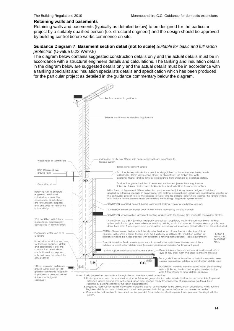
Retaining walls and basements
Retaining walls and basements (typically as detailed below) to be designed for the particular project by a suitably qualified person (i.e. structural engineer) and the design should be approved by building control before works commence on site.
Guidance Diagram 7: Basement section detail (not to scale) Suitable for basic and full radon protection (U-value 0.22 W/m².k) The diagram below contains suggested construction details only and the actual details must be in accordance with a structural engineers details and calculations. The tanking and insulation details in the diagram below are suggested details only and the actual details must be in accordance with a tanking specialist and insulation specialists details and specification which has been produced for the particular project as detailed in the guidance commentary below the diagram.
Roof as detailed in guidance
External cavity walls as detailed in guidance
Weep holes at 900mm ctrs radon dpc cavity tray 225mm min deep sealed with gas proof tape to
tanking system
DPC 150mm above
ground level
Ground level
Retaining wall to structural
engineers details and
calculations - Note: the
construction details shown
are for illustration purposes
only and does not reflect the
actual design
Wall backfilled with 25mm
clean stone, mechanically
compacted in 150mm layers.
50mm sand/cement screed
Pcc floor beams suitable for spans & loadings & fixed as beam manufacterers details
infilled with 100mm dense conc blocks, or alternatively use timber floor joists,
boarding, finishes and 30 minutes fire resistance from underside as guidance details.
Provide floor grade insulation if basement is unheated (see options in guidance
table) & 12.5mm plaster board & skim finishes fixed to battens to underside of floor
British Board of Agreement (BBA or other third party accredited) tanking system designed/ installed/
applied by a tanking specialist in compliance with tanking manufacturer's details and specification specific for
the particualar project to resist the passage of water into the building (and where required the tanking system
must include for the prevent radon gas entering the building). Suggested system shown:
'SOVEREIGN' modified cement based water proof tanking system for use below ground.
'SOVEREIGN' radon gas barrier coat system (where required by building control)
'SOVEREIGN' condensation absorbent coating applied onto the tanking (Sov renderlite renovating plaster).
Alternatively use a BBA (or other third party accredited) proprietary cavity drained membrane tanking
system (with Radon gas barrier where required by building control) connected to a proprietary gravity base
drain, floor drain & packaged sump pump system and designed soakaway (details differ from those illustrated)
Proprietary water stop at all
junctions
Foundations and floor slab
to structural engineers details
and calculations Note: the
75/100 x 50mm treated timber sole & head plates fixed to top of new floor & under side of floor
structure, with 75/100 x 50mm treated studs fixed vertically at 400mm ctrs - insulation position in
relation to wall to be in accordance with insulation & tanking manufacturer's spec requirements
Thermal insulation fixed between/over studs to insulation manufacturers U-value calculations
suitable for construction details used (insulation position as insulation/tanking manf spec)
HEATED &
VENTILATED
BASEMENT
AREA
construction details shown
are for illustration purposes
only and does not reflect the
actual design
100mm diameter perferated
ground water drain at 1:60
gradient connected to gravity
12.5mm vapour checked plaster board & skim 75mm minimum thickness cement & sand screed with a
layer of galv steel mesh mid span to prevent cracking
Floor grade thermal insulation to insulation manufacturers
U-value calculations suitable for construction details used
'SOVEREIGN' modified cement based water proof tanking
system (& Radon barrier coat) applied to all enclosing
walls & top of floor as manf details- as above or proprietary pumped outfall
& taken to designed
soakaway
Notes: 1. All pipe/service penatrations through the sub structure should be avoided
2. Radon gas sump and depressurisation pipe for full radon gas protection to be installed below the concrete slab & upstand
extended above ground level with cap & radon pipe signage ready for connection of future radon gas fan & flue if
required by building control for full radon gas protection
3. Suggested construction details have been indicated above- actual design to be carried out in accordance with Structural
Engineers details and calculations which must be approved by building control before works commence on site.
4. Condensation risk analysis to be carried out by specialist for a particular situation/project and proposed tanking/insulation
system.
15
The Building Regulations 2010 Monmouthshire C.C. Guidance for domestic extensions
Basements and tanking systems Site investigation and risk assessment to be carried out before works commence to establish: ground conditions and water table levels, presence of any contaminates and radon gas, including location of drains and services etc.
Basement sub structures to be constructed in compliance with structural engineers details and calculations suitable for the ground conditions, loadings and proposed tanking system.
Provide all necessary temporary protection, support, shoring and working platforms etc in compliance with current health and safety requirements and structural engineer's details which are to be erected, maintained, certificated, dismantled and removed by suitably qualified and insured specialist.
Tanking systems providing either barrier, structural or drained protection to the building must be assessed, designed and installed for the particular project in compliance with BS 8102: 2009 Code of Practice for Protection of Below Ground Structures Against Water from The Ground. Tanking systems can be installed internally or externally in accordance with a tanking specialists details.
The illustrated tanking section details above are suggested details only and actual details must be approved by building control before works commence on site. Forms of tanking include: bonded sheet materials; liquid applied membranes; mastic asphalt, drained cavity membranes and cementitious crystallization and cementitious multi coat renders.
Suitable tanking systems to have British Board of Agreement (BBA or other approved third party) accreditation and individually assessed by a tanking specialist as suitable for the proposed situation.
Tanking systems must be designed/installed/applied by a tanking specialist for the particular project in compliance with tanking manufacturer's details to resist the passage of water into the building and prevent condensation and mould growth within the building and where required prevent radon gas entering the building.
Tanking systems to be properly connected to and made continuous with wall damp proof courses/radon dpc trays. Perforation of the tanking system by service entry pipes etc should be avoided or carried out strictly in accordance with the tanking manufacturer's details.
Important note: The risk of condensation with any tanking system should be assessed by a specialist, a condensation risk analysis should be carried out for the particular project and the tanking and thermal insulation system should be designed and installed to prevent any potential condensation/ interstitial condensation problems.
16
The Building Regulations 2010 Monmouthshire C.C. Guidance for domestic extensions
Ground floors and sub structure walls
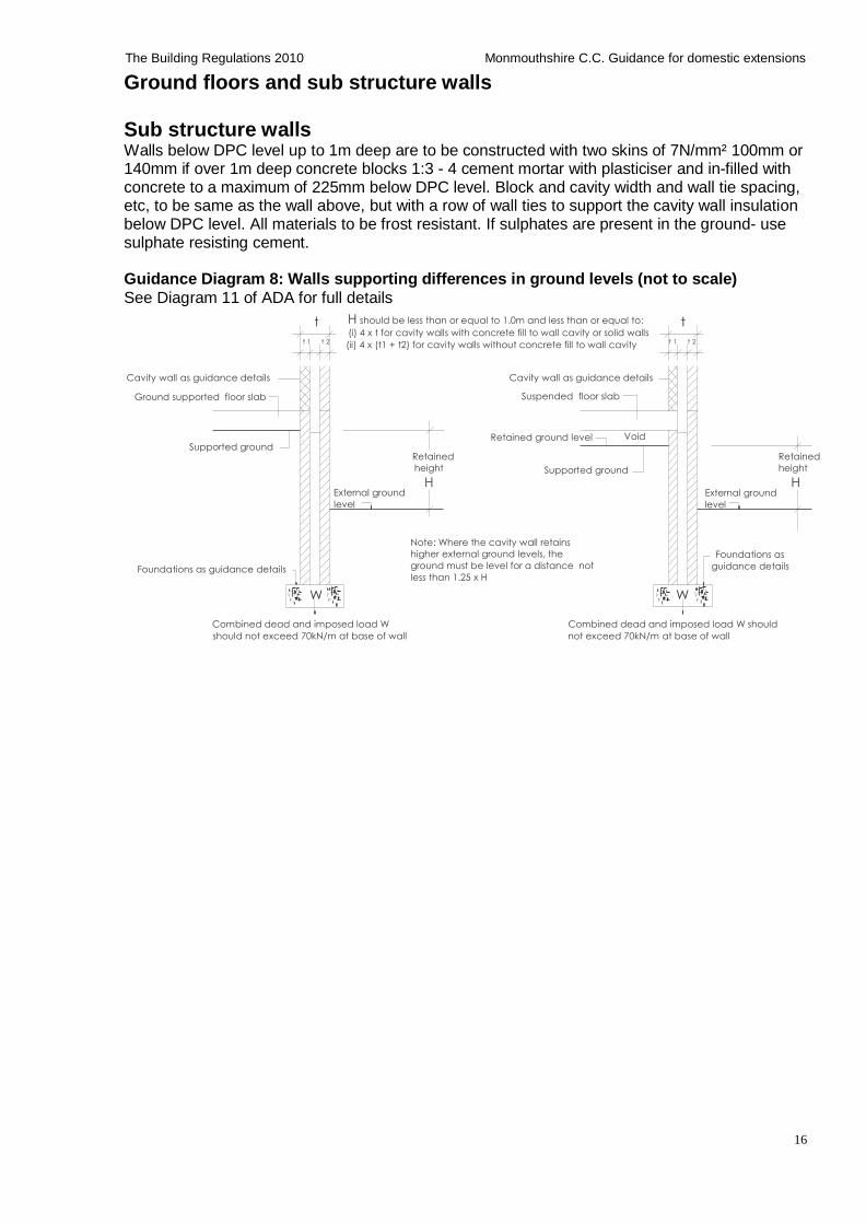
Sub structure walls Walls below DPC level up to 1m deep are to be constructed with two skins of 7N/mm² 100mm or 140mm if over 1m deep concrete blocks 1:3 - 4 cement mortar with plasticiser and in-filled with concrete to a maximum of 225mm below DPC level. Block and cavity width and wall tie spacing, etc, to be same as the wall above, but with a row of wall ties to support the cavity wall insulation below DPC level. All materials to be frost resistant. If sulphates are present in the ground- use sulphate resisting cement.
Guidance Diagram 8: Walls supporting differences in ground levels (not to scale)
See Diagram 11 of ADA for full details
t H should be less than or equal to 1.0m and less than or equal to: t (i) 4 x t for cavity walls with concrete fill to wall cavity or solid walls
t 1 t 2 (ii) 4 x (t1 + t2) for cavity walls without concrete fill to wall cavity t 1 t 2
Cavity wall as guidance details
Ground supported floor slab
Cavity wall as guidance details
Suspended floor slab
Supported ground
Retained
Retained ground level Void
Retained
height Supported ground height
External ground
level
H H External ground
level
Foundations as guidance details
W
Note: Where the cavity wall retains
higher external ground levels, the
ground must be level for a distance not
less than 1.25 x H
Foundations as
guidance details
W
Combined dead and imposed load W
should not exceed 70kN/m at base of wall
Combined dead and imposed load W should
not exceed 70kN/m at base of wall
17
The Building Regulations 2010 Monmouthshire C.C. Guidance for domestic extensions
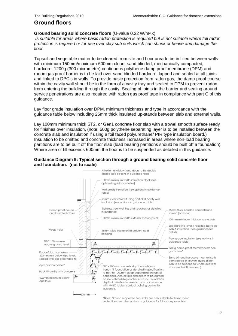
Ground floors Ground bearing solid concrete floors (U-value 0.22 W/m².k)
Is suitable for areas where basic radon protection is required but is not suitable where full radon protection is required or for use over clay sub soils which can shrink or heave and damage the floor.
Topsoil and vegetable matter to be cleared from site and floor area to be in filled between walls with minimum 150mm/maximum 600mm clean, sand blinded, mechanically compacted, hardcore. 1200g (300 micrometer) continuous polythene damp proof membrane (DPM) and radon gas proof barrier is to be laid over sand blinded hardcore, lapped and sealed at all joints and linked to DPC’s in walls. To provide basic protection from radon gas, the damp-proof course within the cavity wall should be in the form of a cavity tray and sealed to DPM to prevent radon from entering the building through the cavity. Sealing of joints in the barrier and sealing around service penetrations are also required with radon gas proof tape in compliance with part C of this guidance.
Lay floor grade insulation over DPM, minimum thickness and type in accordance with the guidance table below including 25mm thick insulated up-stands between slab and external walls.
Lay 100mm minimum thick ST2, or Gen1 concrete floor slab with a trowel smooth surface ready for finishes over insulation, (note: 500g polythene separating layer is to be installed between the concrete slab and insulation if using a foil faced polyurethane/ PIR type insulation board.) Insulation to be omitted and concrete thickness increased in areas where non-load bearing partitions are to be built off the floor slab (load bearing partitions should be built off a foundation). Where area of fill exceeds 600mm the floor is to be suspended as detailed in this guidance.
Guidance Diagram 9: Typical section through a ground bearing solid concrete floor and foundation. (not to scale)
All external widows and doors to be double
glazed (see options in guidance table)
100mm minimum width insulation block (see
options in guidance table)
Wall grade insulation (see options in guidance
table)
Damp proof course
and insulated closer
Weep holes
DPC 150mm min
above ground level
Radon/dpc tray taken
225mm min below dpc level,
sealed with gas proof tape to
dpm/ radon barrier*
Back fill cavity with concrete
225mm minimum below
dpc level
600mm
50mm clear cavity if using partial fill cavity wall
insulation (see options in guidance table) Stainless steel wall ties and spacings as detailed
in guidance 100mm minimum width external masonry wall
25mm wide insulation to prevent cold
bridging
600 x 200mm concrete strip foundation or
trench fill foundation as detailed in specification,
to be 750-1000mm deep depending on sub soil
conditions. Actual sizes and depth to be agreed
on site with building control surveyor. Foundation
depths in relation to trees to be in accordance
with NHBC tables- contact building control for
guidance.
65mm thick bonded cement/sand
screed (optional) 100mm minimum thick concrete slab
Separarating layer if required beween
slab & insulation - see guidance for
details
Floor grade insulation (see options in
guidance table) 1200g damp proof membrane/radon
gas barrier*
Sand blinded hardcore mechanically
compacted in 150mm layers. (floor
slab to be suspended where depth of
fill exceeds 600mm deep)
*Note: Ground supported floor slabs are only suitable for basic radon
protection- see other options in guidance for full radon protection.
18
The Building Regulations 2010 Monmouthshire C.C. Guidance for domestic extensions
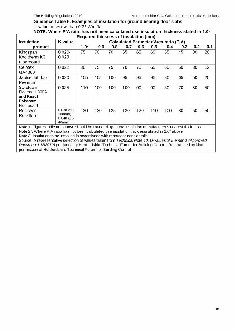
Guidance Table 5: Examples of insulation for ground bearing floor slabs
U-value no worse than 0.22 W/m²k NOTE: Where P/A ratio has not been calculated use insulation thickness stated in 1.0*
Required thickness of insulation (mm)
Insulation product
K value Calculated Perimeter/Area ratio (P/A) 1.0* 0.9 0.8 0.7 0.6 0.5 0.4 0.3 0.2 0.1
Kingspan Kooltherm K3 Floorboard
0.020- 0.023
75 70 70 65 65 60 55 45 30 20
Celotex GA4000
0.022 80 75 75 70 70 65 60 50 30 12
Jablite Jabfloor Premium
0.030 105 105 100 95 95 95 80 65 50 20
Styrofoam Floormate 300A and Knauf Polyfoam Floorboard
0.035 110 100 100 100 90 90 80 70 50 50
Rockwool Rockfloor
0.038 (50- 100mm) 0.040 (25- 40mm)
130 130 125 120 120 110 100 80 50 50
Note 1. Figures indicated above should be rounded up to the insulation manufacturer's nearest thickness Note 2*. Where P/A ratio has not been calculated use insulation thickness stated in 1.0* above Note 3. Insulation to be installed in accordance with manufacturer's details Source: A representative selection of values taken from Technical Note 10, U-values of Elements (Approved Document L1B2010) produced by Hertfordshire Technical Forum for Building Control. Reproduced by kind
permission of Hertfordshire Technical Forum for Building Control
19
The Building Regulations 2010 Monmouthshire C.C. Guidance for domestic extensions
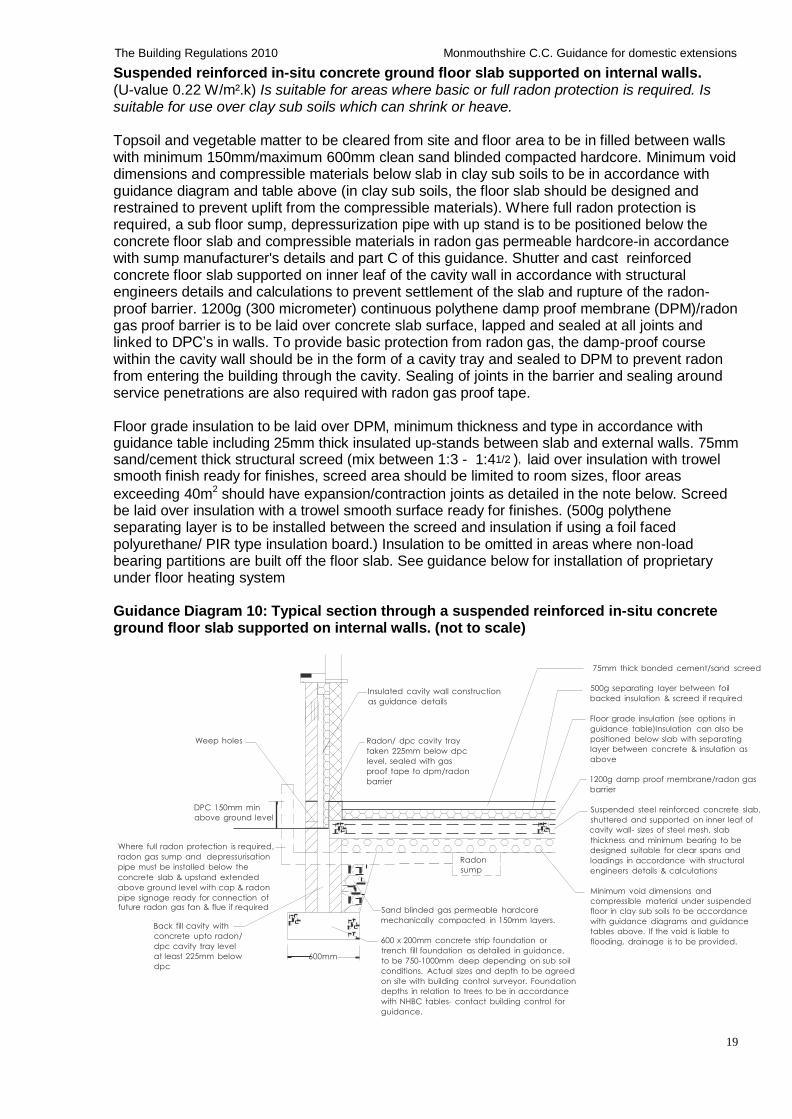
Suspended reinforced in-situ concrete ground floor slab supported on internal walls. (U-value 0.22 W/m².k) Is suitable for areas where basic or full radon protection is required. Is suitable for use over clay sub soils which can shrink or heave.
Topsoil and vegetable matter to be cleared from site and floor area to be in filled between walls with minimum 150mm/maximum 600mm clean sand blinded compacted hardcore. Minimum void dimensions and compressible materials below slab in clay sub soils to be in accordance with guidance diagram and table above (in clay sub soils, the floor slab should be designed and restrained to prevent uplift from the compressible materials). Where full radon protection is required, a sub floor sump, depressurization pipe with up stand is to be positioned below the concrete floor slab and compressible materials in radon gas permeable hardcore-in accordance with sump manufacturer's details and part C of this guidance. Shutter and cast reinforced concrete floor slab supported on inner leaf of the cavity wall in accordance with structural engineers details and calculations to prevent settlement of the slab and rupture of the radon- proof barrier. 1200g (300 micrometer) continuous polythene damp proof membrane (DPM)/radon gas proof barrier is to be laid over concrete slab surface, lapped and sealed at all joints and linked to DPC’s in walls. To provide basic protection from radon gas, the damp-proof course within the cavity wall should be in the form of a cavity tray and sealed to DPM to prevent radon from entering the building through the cavity. Sealing of joints in the barrier and sealing around service penetrations are also required with radon gas proof tape.
Floor grade insulation to be laid over DPM, minimum thickness and type in accordance with guidance table including 25mm thick insulated up-stands between slab and external walls. 75mm sand/cement thick structural screed (mix between 1:3 - 1:41/2 ), laid over insulation with trowel smooth finish ready for finishes, screed area should be limited to room sizes, floor areas
exceeding 40m2 should have expansion/contraction joints as detailed in the note below. Screed be laid over insulation with a trowel smooth surface ready for finishes. (500g polythene separating layer is to be installed between the screed and insulation if using a foil faced polyurethane/ PIR type insulation board.) Insulation to be omitted in areas where non-load bearing partitions are built off the floor slab. See guidance below for installation of proprietary under floor heating system
Guidance Diagram 10: Typical section through a suspended reinforced in-situ concrete ground floor slab supported on internal walls. (not to scale)
75mm thick bonded cement/sand screed
Insulated cavity wall construction
as guidance details
500g separating layer between foil
backed insulation & screed if required
Weep holes
DPC 150mm min
above ground level
Where full radon protection is required,
radon gas sump and depressurisation
pipe must be installed below the
concrete slab & upstand extended
above ground level with cap & radon
pipe signage ready for connection of
Radon/ dpc cavity tray
taken 225mm below dpc
level, sealed with gas
proof tape to dpm/radon
barrier
Radon
sump
Floor grade insulation (see options in
guidance table)Insulation can also be
positioned below slab with separating
layer between concrete & insulation as
above
1200g damp proof membrane/radon gas
barrier
Suspended steel reinforced concrete slab,
shuttered and supported on inner leaf of
cavity wall- sizes of steel mesh, slab
thickness and minimum bearing to be
designed suitable for clear spans and
loadings in accordance with structural
engineers details & calculations
Minimum void dimensions and
compressible material under suspended future radon gas fan & flue if required
Back fill cavity with
concrete upto radon/
dpc cavity tray level
at least 225mm below
dpc
600mm
Sand blinded gas permeable hardcore
mechanically compacted in 150mm layers.
600 x 200mm concrete strip foundation or
trench fill foundation as detailed in guidance,
to be 750-1000mm deep depending on sub soil
conditions. Actual sizes and depth to be agreed
on site with building control surveyor. Foundation
depths in relation to trees to be in accordance
with NHBC tables- contact building control for
guidance.
floor in clay sub soils to be accordance
with guidance diagrams and guidance
tables above. If the void is liable to
flooding, drainage is to be provided.
20
The Building Regulations 2010 Monmouthshire C.C. Guidance for domestic extensions
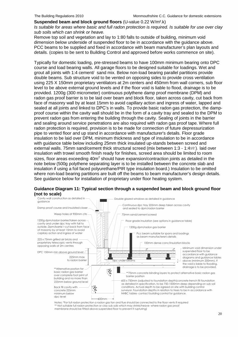
Suspended beam and block ground floors (U-value 0.22 W/m².k)
Is suitable for areas where basic and full radon protection is required. Is suitable for use over clay sub soils which can shrink or heave. Remove top soil and vegetation and lay to 1:80 falls to outside of building, minimum void dimension below underside of suspended floor to be in accordance with the guidance above. PCC beams to be supplied and fixed in accordance with beam manufacturer’s plan layouts and details. (copies to be sent to Building Control and approved before works commence on site).
Typically for domestic loading, pre-stressed beams to have 100mm minimum bearing onto DPC course and load bearing walls. All garage floors to be designed suitable for loadings. Wet and grout all joints with 1:4 cement/ sand mix. Below non-load bearing parallel partitions provide double beams. Sub structure void to be vented on opposing sides to provide cross ventilation using 225 X 150mm proprietary ventilators at 2m centers and 450mm from wall corners, sub floor level to be above external ground levels and if the floor void is liable to flood, drainage is to be provided. 1200g (300 micrometer) continuous polythene damp proof membrane (DPM) and radon gas proof barrier is to be laid over beam and block floor, taken across cavity, cut back from face of masonry wall by at least 15mm to avoid capillary action and ingress of water, lapped and sealed at all joints and linked to DPC’s in walls. To provide basic radon gas protection, the damp- proof course within the cavity wall should be in the form of a cavity tray and sealed to the DPM to prevent radon gas from entering the building through the cavity. Sealing of joints in the barrier and sealing around service penetrations are also required with radon gas proof tape. Where full radon protection is required, provision is to be made for connection of future depressurization pipe to vented floor and up stand in accordance with manufacturer's details. Floor grade insulation to be laid over DPM, minimum thickness and type of insulation to be in accordance with guidance table below including 25mm thick insulated up-stands between screed and external walls. 75mm sand/cement thick structural screed (mix between 1:3 - 1:41/2 ), laid over insulation with trowel smooth finish ready for finishes, screed area should be limited to room
sizes, floor areas exceeding 40m2 should have expansion/contraction joints as detailed in the note below (500g polythene separating layer is to be installed between the concrete slab and insulation if using a foil faced polyurethane/PIR type insulation board.) Insulation to be omitted where non-load bearing partitions are built off the beams to beam manufacturer's design details. See guidance below for installation of proprietary under floor heating system.
Guidance Diagram 11: Typical section through a suspended beam and block ground floor (not to scale)
Cavity wall construction as detailed in
guidance
Damp proof course and insulated closer
Weep holes at 900mm ctrs
1200g dpm/radon barrier/taken across
cavity and under dpc tray with fall to
outside. Dpm/barrie`r cut back from face
of masonry by at least 15mm to avoid
capilary action and ingress of water
225 x 75mm grilled air bricks and
proprietary telescopic vents through
opposing walls at 2m centres
DPC 150mm min above ground level
225mm max
Double glazed windows as detailed in guidance
Continuous dpc tray 225mm deep taken across cavity
and sealed to dpm/radon barrier
75mm sand/cement screed
Floor grade insulation (see options in guidance table)
1200g dpm/radon gas barrier
Pcc beam suitable for spans and loadings
as beam manufacterer's details
100mm dense conc/insulation blocks
Minimum void dimension under
suspended floor to be
accordance with guidance
diagrams and guidance tables to radon barrier
**Alternative postion for
dpc under beams above (minimum 200mm). If
the void is liable to flooding,
drainage is to be provided.
basic radon gas barrier
over complete foot print of
building and no more than
**75mm concrete blinding layers to protect alternative basic radon gas
barrier position
225mm below ground level 600 x 750mm (adjusted to foundation depth)concrete trench fill foundation
as detailed in specification, to be 750-1000mm deep depending on sub soil
Back fill cavity with
concrete 225mm
minimum below
dpc level
600mm
conditions. Actual depth to be agreed on site with building control
surveyor. Foundation depths in relation to trees to be in accordance with
NHBC tables- contact building control for guidance.
Notes: *For full radon protection a radon gas fan and flue should be connected to the floor vents if required
** Not suitable full radon protection or clay sub soils which may shrink/heave- where radon gas proof
membrane should be fitted above suspended floor to prevent it rupturing)
21
The Building Regulations 2010 Monmouthshire C.C. Guidance for domestic extensions
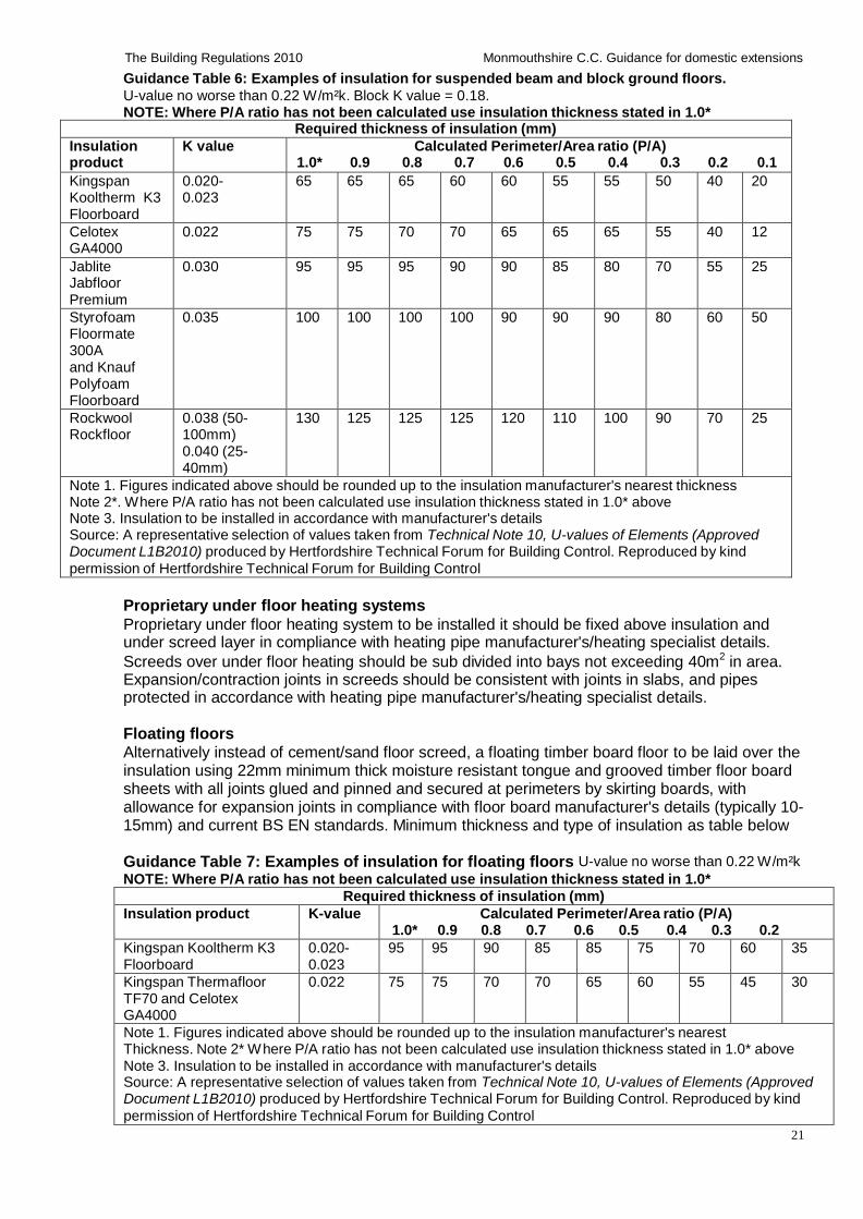
Guidance Table 6: Examples of insulation for suspended beam and block ground floors.
U-value no worse than 0.22 W/m²k. Block K value = 0.18. NOTE: Where P/A ratio has not been calculated use insulation thickness stated in 1.0*
Required thickness of insulation (mm)
Insulation product
K value Calculated Perimeter/Area ratio (P/A) 1.0* 0.9 0.8 0.7 0.6 0.5 0.4 0.3 0.2 0.1
Kingspan Kooltherm K3 Floorboard
0.020- 0.023
65 65 65 60 60 55 55 50 40 20
Celotex GA4000
0.022 75 75 70 70 65 65 65 55 40 12
Jablite Jabfloor Premium
0.030 95 95 95 90 90 85 80 70 55 25
Styrofoam Floormate 300A and Knauf Polyfoam Floorboard
0.035 100 100 100 100 90 90 90 80 60 50
Rockwool Rockfloor
0.038 (50- 100mm) 0.040 (25- 40mm)
130 125 125 125 120 110 100 90 70 25
Note 1. Figures indicated above should be rounded up to the insulation manufacturer's nearest thickness Note 2*. Where P/A ratio has not been calculated use insulation thickness stated in 1.0* above Note 3. Insulation to be installed in accordance with manufacturer's details Source: A representative selection of values taken from Technical Note 10, U-values of Elements (Approved Document L1B2010) produced by Hertfordshire Technical Forum for Building Control. Reproduced by kind
permission of Hertfordshire Technical Forum for Building Control
Proprietary under floor heating systems
Proprietary under floor heating system to be installed it should be fixed above insulation and under screed layer in compliance with heating pipe manufacturer's/heating specialist details.
Screeds over under floor heating should be sub divided into bays not exceeding 40m2 in area. Expansion/contraction joints in screeds should be consistent with joints in slabs, and pipes protected in accordance with heating pipe manufacturer's/heating specialist details.
Floating floors Alternatively instead of cement/sand floor screed, a floating timber board floor to be laid over the insulation using 22mm minimum thick moisture resistant tongue and grooved timber floor board sheets with all joints glued and pinned and secured at perimeters by skirting boards, with allowance for expansion joints in compliance with floor board manufacturer's details (typically 10- 15mm) and current BS EN standards. Minimum thickness and type of insulation as table below
Guidance Table 7: Examples of insulation for floating floors U-value no worse than 0.22 W/m²k
NOTE: Where P/A ratio has not been calculated use insulation thickness stated in 1.0*
Required thickness of insulation (mm)
Insulation product K-value Calculated Perimeter/Area ratio (P/A) 1.0* 0.9 0.8 0.7 0.6 0.5 0.4 0.3 0.2
Kingspan Kooltherm K3 Floorboard
0.020- 0.023
95 95 90 85 85 75 70 60 35
Kingspan Thermafloor TF70 and Celotex GA4000
0.022 75 75 70 70 65 60 55 45 30
Note 1. Figures indicated above should be rounded up to the insulation manufacturer's nearest Thickness. Note 2* Where P/A ratio has not been calculated use insulation thickness stated in 1.0* above Note 3. Insulation to be installed in accordance with manufacturer's details Source: A representative selection of values taken from Technical Note 10, U-values of Elements (Approved Document L1B2010) produced by Hertfordshire Technical Forum for Building Control. Reproduced by kind
permission of Hertfordshire Technical Forum for Building Control
22
The Building Regulations 2010 Monmouthshire C.C. Guidance for domestic extensions
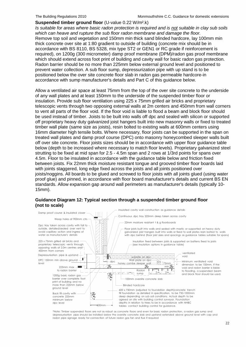
Suspended timber ground floor (U-value 0.22 W/m².k)
Is suitable for areas where basic radon protection is required and is not suitable in clay sub soils which can heave and rupture the sub floor radon membrane and damage the floor. Remove top soil and vegetation and 150mm min thick sand blinded hardcore, lay 100mm min thick concrete over site at 1:80 gradient to outside of building (concrete mix should be in accordance with BS 8110, BS 5328, mix type ST2 or GEN1 or RC grade if reinforcement is required), on 1200g (300 micrometer) damp proof membrane (DPM)/radon gas proof membrane which should extend across foot print of building and cavity wall for basic radon gas protection. Radon barrier should be no more than 225mm below external ground level and positioned to prevent water collection. A sub floor sump, depressurization pipe with up stand is to be positioned below the over site concrete floor slab in radon gas permeable hardcore-in accordance with sump manufacturer's details and Part C of this guidance below.
Allow a ventilated air space at least 75mm from the top of the over site concrete to the underside of any wall plates and at least 150mm to the underside of the suspended timber floor or insulation. Provide sub floor ventilation using 225 x 75mm grilled air bricks and proprietary telescopic vents through two opposing external walls at 2m centers and 450mm from wall corners to vent all parts of the floor void. If the floor void is liable to flood a beam and block floor should be used instead of timber. Joists to be built into walls off dpc and sealed with silicon or supported off proprietary heavy duty galvanized joist hangers built into new masonry walls or fixed to treated timber wall plate (same size as joists), resin bolted to existing walls at 600mm centers using 16mm diameter high tensile bolts. Where necessary, floor joists can be supported in the span on treated wall plates and damp proof course (DPC) onto masonry honeycombed sleeper walls built off over site concrete. Floor joists sizes should be in accordance with upper floor guidance table below (depth to be increased where necessary to match floor levels). Proprietary galvanized steel strutting to be fixed at mid span for 2.5 - 4.5m span and 2 rows at 1/3rd points for spans over 4.5m. Floor to be insulated in accordance with the guidance table below and friction fixed between joists. Fix 22mm thick moisture resistant tongue and grooved timber floor boards laid with joints staggered, long edge fixed across the joists and all joints positioned over joists/noggins. All boards to be glued and screwed to floor joists with all joints glued (using water proof glue) and pinned, in accordance with floor board manufacturer's details and current BS EN standards. Allow expansion gap around wall perimeters as manufacturer's details (typically 10- 15mm).
Guidance Diagram 12: Typical section through a suspended timber ground floor
(not to scale)
Damp proof course & insulated closer
Weep holes at 900mm ctrs
Dpc tray taken across cavity with fall to
outside, detailed/sealed over vent to
avoid capillary action and ingress of
water as manufacturer's details
225 x 75mm grilled air bricks and
proprietary telescopic vents through
opposing walls at 2.0m centres and
450mm from corners
Depressurisation pipe & upstand
Insulated cavity wall construction as guidance details
Continuous dpc tray 225mm deep taken across cavity
22mm moisture resistant t & g floorboards
Floor joists built into walls and sealed with mastic or supported on heavy duty
galvanized joist hangers built into walls or fixed to wall plates resin bolted to walls
with dpc behind (floor joist sizes and spacings as guidance tables suitable for spans)
Insulation fixed between joists & supported on battens fixed to joists
(see insulation options in guidance table)
ventilated
DPC 150mm min above ground
level
225mm max
dpc
w/plate on dpc
Wall plate on dpc
honey combe sleeper wall 75mm
min
void
Minimum ventilated void
dimension to be 150mm. If the
void and radon barrier is liable to radon barrier
1200g basic radon gas
Radon
sump to flooding, a suspended beam
and block floor should be used.
barrier over complete foot
print of building and no
more than 225mm below
ground level
Back fill cavity with
concrete 225mm
minimum below
dpc level
600mm
100mm oversite concrete slab
Blinded hardcore
600 x 750mm (adjusted to foundation depth)concrete trench
fill foundation as detailed in specification, to be 750-1000mm
deep depending on sub soil conditions. Actual depth to be
agreed on site with building control surveyor. Foundation
depths in relation to trees to be in accordance with NHBC
tables- contact building control for guidance.
*Note: Timber suspended floors are not as robust as concrete floors and even for basic radon protection, a radon gas sump and
depressurisation pipe should be installed below the oversite concrete slab and upstand extended above ground level with cap and
radon pipe signage ready for connection of future radon gas fan and flue if required
23
The Building Regulations 2010 Monmouthshire C.C. Guidance for domestic extensions
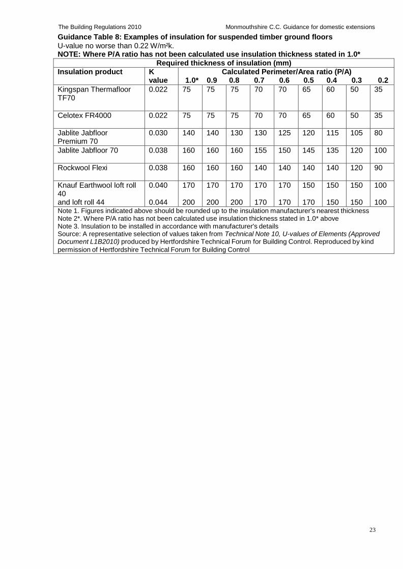
Guidance Table 8: Examples of insulation for suspended timber ground floors
U-value no worse than 0.22 W/m²k. NOTE: Where P/A ratio has not been calculated use insulation thickness stated in 1.0*
Required thickness of insulation (mm)
Insulation product K value
Calculated Perimeter/Area ratio (P/A) 1.0* 0.9 0.8 0.7 0.6 0.5 0.4 0.3 0.2
Kingspan Thermafloor TF70
0.022 75 75 75 70 70 65 60 50 35
Celotex FR4000 0.022 75 75 75 70 70 65 60 50 35
Jablite Jabfloor Premium 70
0.030 140 140 130 130 125 120 115 105 80
Jablite Jabfloor 70 0.038 160 160 160 155 150 145 135 120 100
Rockwool Flexi 0.038 160 160 160 140 140 140 140 120 90
Knauf Earthwool loft roll 40 and loft roll 44
0.040 0.044
170 200
170 200
170 200
170 170
170 170
150 170
150 150
150 150
100 100
Note 1. Figures indicated above should be rounded up to the insulation manufacturer's nearest thickness Note 2*. Where P/A ratio has not been calculated use insulation thickness stated in 1.0* above Note 3. Insulation to be installed in accordance with manufacturer's details Source: A representative selection of values taken from Technical Note 10, U-values of Elements (Approved Document L1B2010) produced by Hertfordshire Technical Forum for Building Control. Reproduced by kind
permission of Hertfordshire Technical Forum for Building Control
24
The Building Regulations 2010 Monmouthshire C.C. Guidance for domestic extensions
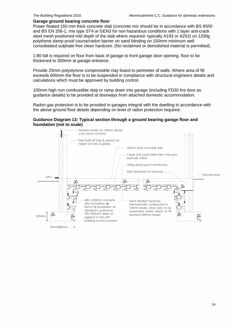
Garage ground bearing concrete floor
Power floated 150 mm thick concrete slab (concrete mix should be in accordance with BS 8500 and BS EN 206-1, mix type ST4 or GEN3 for non hazardous conditions with 1 layer anti-crack steel mesh positioned mid depth of the slab where required- typically A193 or A252) on 1200g polythene damp proof course/radon barrier on sand blinding on 150mm minimum well consolidated sulphate free clean hardcore. (No reclaimed or demolished material is permitted).
1:80 fall is required on floor from back of garage to front garage door opening, floor to be thickened to 300mm at garage entrance.
Provide 25mm polystyrene compressible clay board to perimeter of walls. Where area of fill exceeds 600mm the floor is to be suspended in compliance with structural engineers details and calculations which must be approved by building control.
100mm high non combustible step or ramp down into garage (including FD30 fire door as guidance details) to be provided at doorways from attached domestic accommodation.
Radon gas protection is to be provided in garages integral with the dwelling in accordance with the above ground floor details depending on level of radon protection required.
Guidance Diagram 13: Typical section through a ground bearing garage floor and foundation (not to scale)
Painted render on 100mm dense
conc block or bricks
Piers built off fnds & extend full
height of walls & gables
150mm thick concrete slab
1 layer anti crack steel mesh mid span
(typically A252)
1200g damp proof membrane
DPC
Slab thickened at doorway Ground level
225mm
600 x 225mm concrete
strip foundation or
trench fill foundation as
detailed in guidance,
750-1000mm deep as
agreed on site with
building control surveyor
Sand blinded hardcore
mechanically compacted in
150mm layers. (floor slab to be
suspended where depth of fill
exceeds 600mm deep)
600mm
25
The Building Regulations 2010 Monmouthshire C.C. Guidance for domestic extensions
A2: Superstructure Minimum headroom heights There are no minimum head room height requirements in the building regulations for habitable rooms in single occupancy dwellings except for stairs and ramps (see Part K of this guidance), however a minimum ceiling height of 2.3m is recommended.
Maximum height of residential buildings up to 3 storeys See paragraph 2C4 and Diagram 1 of ADA.
(i) The maximum height of the building constructed of coursed brick or block work measured from the lowest finished ground level adjoining the building to the highest point of any wall or roof should not be greater than 15m, subject to paragraph 2C16 and Tables a, b and c of Diagram 7 of ADA, correlating to various site exposure conditions and wind speeds. A map showing wind speeds and topographic zones is given in Diagram 6 of ADA. (ii) The height of the building H should not exceed twice the least width of the building W1 (iii) The height of wing H2 should not exceed twice the least width of the wing W2 where the projection P exceeds twice the width W2. (iv) Floor area limit should not exceed the following: 70m2 where floor is bounded by walls on all 4 sides and 36m2 where floor is bounded by walls on 3 sides
Maximum storey heights
Storey heights should not exceed 2.7m in accordance with Diagram 8 of ADA for buildings constructed of coursed brick or block work.
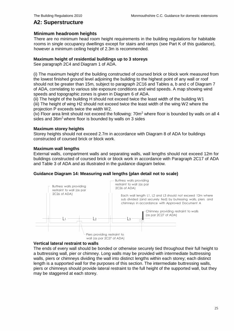
Maximum wall lengths
External walls, compartment walls and separating walls, wall lengths should not exceed 12m for buildings constructed of coursed brick or block work in accordance with Paragraph 2C17 of ADA and Table 3 of ADA and as illustrated in the guidance diagram below.
Guidance Diagram 14: Measuring wall lengths (plan detail not to scale)
Buttress walls providing
restraint to wall (as par
2C26 of ADA)
Buttress walls providing
restraint to wall (as par
2C26 of ADA)
Each wall length L1, L2 and L3 should not exceed 12m where
sub divided (and securely tied) by butressing walls, piers and
chimneys in accordance with Approved Document A
L1 L2 L3
Chimney providing restraint to walls
(as par 2C27 of ADA)
Piers providing restraint to
wall (as par 2C27 of ADA)
Vertical lateral restraint to walls The ends of every wall should be bonded or otherwise securely tied throughout their full height to a buttressing wall, pier or chimney. Long walls may be provided with intermediate buttressing walls, piers or chimneys dividing the wall into distinct lengths within each storey; each distinct length is a supported wall for the purposes of this section. The intermediate buttressing walls, piers or chimneys should provide lateral restraint to the full height of the supported wall, but they may be staggered at each storey.
26
The Building Regulations 2010 Monmouthshire C.C. Guidance for domestic extensions
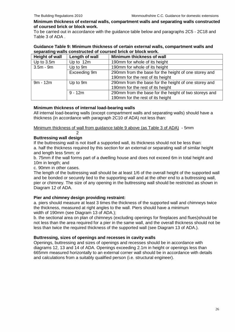
Minimum thickness of external walls, compartment walls and separating walls constructed of coursed brick or block work. To be carried out in accordance with the guidance table below and paragraphs 2C5 - 2C18 and Table 3 of ADA .
Guidance Table 9: Minimum thickness of certain external walls, compartment walls and separating walls constructed of coursed brick or block work.
Height of wall Length of wall Minimum thickness of wall
Up to 3.5m Up to 12m 190mm for whole of its height
3.5m - 9m Up to 9m 190mm for whole of its height
Exceeding 9m 290mm from the base for the height of one storey and 190mm for the rest of its height
9m - 12m Up to 9m 290mm from the base for the height of one storey and 190mm for the rest of its height
9 - 12m 290mm from the base for the height of two storeys and 190mm for the rest of its height
Minimum thickness of internal load-bearing walls
All internal load-bearing walls (except compartment walls and separating walls) should have a thickness (in accordance with paragraph 2C10 of ADA) not less than:
Minimum thickness of wall from guidance table 9 above (as Table 3 of ADA) - 5mm
2 Buttressing wall design If the buttressing wall is not itself a supported wall, its thickness should not be less than: a. half the thickness required by this section for an external or separating wall of similar height and length less 5mm; or b. 75mm if the wall forms part of a dwelling house and does not exceed 6m in total height and 10m in length; and c. 90mm in other cases. The length of the buttressing wall should be at least 1/6 of the overall height of the supported wall and be bonded or securely tied to the supporting wall and at the other end to a buttressing wall, pier or chimney. The size of any opening in the buttressing wall should be restricted as shown in Diagram 12 of ADA.
Pier and chimney design providing restraint:
a. piers should measure at least 3 times the thickness of the supported wall and chimneys twice the thickness, measured at right angles to the wall. Piers should have a minimum width of 190mm (see Diagram 13 of ADA.); b. the sectional area on plan of chimneys (excluding openings for fireplaces and flues)should be not less than the area required for a pier in the same wall, and the overall thickness should not be less than twice the required thickness of the supported wall (see Diagram 13 of ADA.).
Buttressing, sizes of openings and recesses in cavity walls
Openings, buttressing and sizes of openings and recesses should be in accordance with diagrams 12, 13 and 14 of ADA. Openings exceeding 2.1m in height or openings less than 665mm measured horizontally to an external corner wall should be in accordance with details and calculations from a suitably qualified person (i.e. structural engineer).
27
The Building Regulations 2010 Monmouthshire C.C. Guidance for domestic extensions
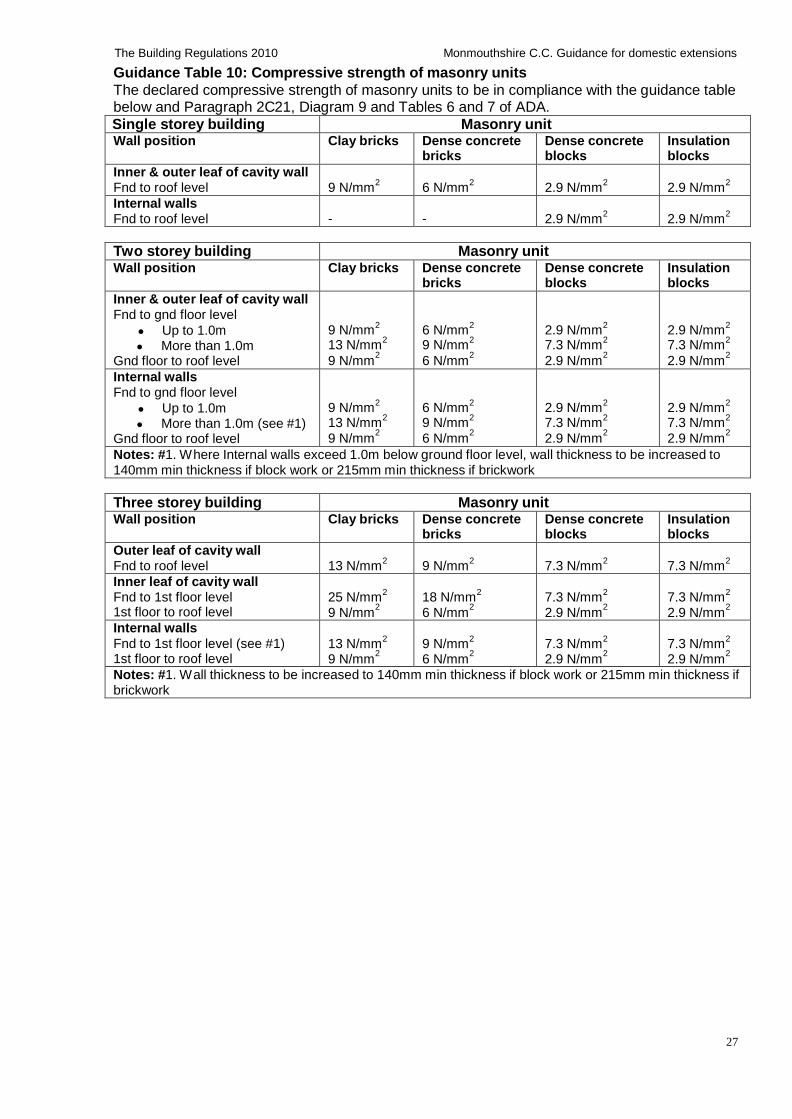
Guidance Table 10: Compressive strength of masonry units
The declared compressive strength of masonry units to be in compliance with the guidance table below and Paragraph 2C21, Diagram 9 and Tables 6 and 7 of ADA.
Single storey building Masonry unit Wall position Clay bricks Dense concrete
bricks Dense concrete blocks
Insulation blocks
Inner & outer leaf of cavity wall Fnd to roof level
9 N/mm2
6 N/mm2
2.9 N/mm2
2.9 N/mm2
Internal walls Fnd to roof level
-
-
2.9 N/mm2
2.9 N/mm2
Two storey building Masonry unit Wall position Clay bricks Dense concrete
bricks Dense concrete blocks
Insulation blocks
Inner & outer leaf of cavity wall Fnd to gnd floor level
Up to 1.0m More than 1.0m
Gnd floor to roof level
9 N/mm2
13 N/mm2
9 N/mm2
6 N/mm2
9 N/mm2
6 N/mm2
2.9 N/mm2
7.3 N/mm2
2.9 N/mm2
2.9 N/mm2
7.3 N/mm2
2.9 N/mm2
Internal walls Fnd to gnd floor level
Up to 1.0m More than 1.0m (see #1)
Gnd floor to roof level
9 N/mm2
13 N/mm2
9 N/mm2
6 N/mm2
9 N/mm2
6 N/mm2
2.9 N/mm2
7.3 N/mm2
2.9 N/mm2
2.9 N/mm2
7.3 N/mm2
2.9 N/mm2
Notes: #1. Where Internal walls exceed 1.0m below ground floor level, wall thickness to be increased to 140mm min thickness if block work or 215mm min thickness if brickwork
Three storey building Masonry unit Wall position Clay bricks Dense concrete
bricks Dense concrete blocks
Insulation blocks
Outer leaf of cavity wall Fnd to roof level
13 N/mm2
9 N/mm2
7.3 N/mm2
7.3 N/mm2
Inner leaf of cavity wall Fnd to 1st floor level 1st floor to roof level
25 N/mm2
9 N/mm2
18 N/mm2
6 N/mm2
7.3 N/mm2
2.9 N/mm2
7.3 N/mm2
2.9 N/mm2
Internal walls
Fnd to 1st floor level (see #1) 1st floor to roof level
13 N/mm2
9 N/mm2
9 N/mm2
6 N/mm2
7.3 N/mm2
2.9 N/mm2
7.3 N/mm2
2.9 N/mm2
Notes: #1. Wall thickness to be increased to 140mm min thickness if block work or 215mm min thickness if brickwork
28
The Building Regulations 2010 Monmouthshire C.C. Guidance for domestic extensions
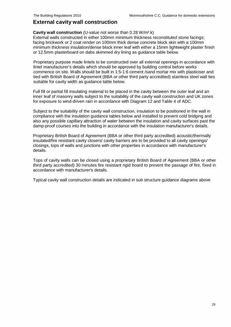
External cavity wall construction Cavity wall construction (U-value not worse than 0.28 W/m².k)
External walls constructed in either 100mm minimum thickness reconstituted stone facings; facing brickwork or 2 coat render on 100mm thick dense concrete block skin with a 100mm minimum thickness insulation/dense block inner leaf with either a 15mm lightweight plaster finish or 12.5mm plasterboard on dabs skimmed dry lining as guidance table below.
Proprietary purpose made lintels to be constructed over all external openings in accordance with lintel manufacturer’s details which should be approved by building control before works commence on site. Walls should be built in 1:5-1:6 cement /sand mortar mix with plasticiser and tied with British Board of Agreement (BBA or other third party accredited) stainless steel wall ties suitable for cavity width as guidance table below.
Full fill or partial fill insulating material to be placed in the cavity between the outer leaf and an inner leaf of masonry walls subject to the suitability of the cavity wall construction and UK zones for exposure to wind-driven rain in accordance with Diagram 12 and Table 4 of ADC.
Subject to the suitability of the cavity wall construction, insulation to be positioned in the wall in compliance with the insulation guidance tables below and installed to prevent cold bridging and also any possible capillary attraction of water between the insulation and cavity surfaces past the damp-proof courses into the building in accordance with the insulation manufacturer's details.
Proprietary British Board of Agreement (BBA or other third party accredited) acoustic/thermally insulated/fire resistant cavity closers/ cavity barriers are to be provided to all cavity openings/ closings, tops of walls and junctions with other properties in accordance with manufacturer's details.
Tops of cavity walls can be closed using a proprietary British Board of Agreement (BBA or other third party accredited) 30 minutes fire resistant rigid board to prevent the passage of fire, fixed in accordance with manufacturer's details.
Typical cavity wall construction details are indicated in sub structure guidance diagrams above
29
The Building Regulations 2010 Monmouthshire C.C. Guidance for domestic extensions
Natural stone faced cavity walls (U-value not worse than 0.28 W/m².k)
100-150mm thick natural stone facings fixed against one of the following backing options to form a uniform cavity within the cavity wall: (i) 100mm thick dense concrete block backing course connected together with stainless steel wall ties as detailed below and foundation widths increased to 750mm as detailed in guidance diagrams 19 and 20 below or; (ii) British Board of Agreement (BBA or other third party accredited) proprietary cavity spacer system installed strictly in accordance with manufacturer's details as detailed in guidance diagrams 21 and 22 below or; (iii) 100mm wide clear continuous cavity, shuttered and formed with temporary shuttering in 450mm vertical stages between wall ties, moved as work proceeds the following day (subject to proposed height of wall and building control approval).
Proprietary purpose made lintels to be constructed over all external openings with extended flange to suit thickness of stone- normally 150mm thick. Lintels must be designed and installed in accordance with lintel manufacturer's details and calculations which should be approved by building control before works commence on site.
Walls should be built in 1:5-1:6 cement /sand mortar mix with plasticiser and tied with British Board of Agreement (BBA or other third party accredited) approved stainless steel wall ties suitable for cavity width as guidance table below.
Cavity wall insulation and insulation inner block skin to be positioned in the wall in compliance with the insulation guidance tables below (together with proprietary insulated closers to prevent cold bridging which have been omitted for clarity). The wall insulation should be continuous with roof insulation level and taken below floor insulation levels in compliance with manufacturer’s details. Guidance Diagram 15: Stone faced cavity wall with concrete block backing forming clear cavity - (section detail not to scale)
All external widows and doors to be double
glazed (see options in guidance table)
Damp proof course between all
internal & external wall junctions
Natural stone sill (optional)
150mm natural stone facings tied to
backing block with stainless steel wall
ties at spacings to suit cavity walls as
guidance details
100mm minimum width dense block
backing
Weep holes at 900mm ctrs
100mm minimum width insulation block closing
cavity at openings with damp proof course at
junctions with external wall (see insulation block
options in guidance table)
Wall grade insulation (see options in guidance
table)
50mm clear cavity if using partial fill cavity wall
insulation (see options in guidance table)
Stainless steel wall ties and spacings as
detailed in guidance
radon dpc tray 225mm deep minimum sealed
with gas proof tape to dpm/radon barrier*
DPC 150mm min
above ground level
radon dpc tray sealed
with gas proof tape to
dpm/radon barrier*
Back fill cavity with
concrete 225mm
minimum below dpc
level
750mm
Floor construction as
detailed in this guidance
750 x 200mm min concrete strip foundation or
trench fill foundation as detailed in specification,
to be 750-1000mm deep depending on sub soil
conditions. Actual sizes and depth to be agreed
on site with building control surveyor. Foundation
depths in relation to trees to be in accordance
with NHBC tables- contact building control for
guidance.
*Note: Ground supported floor slabs are only
suitable for basic radon protection- see other
options in guidance for full radon protection.
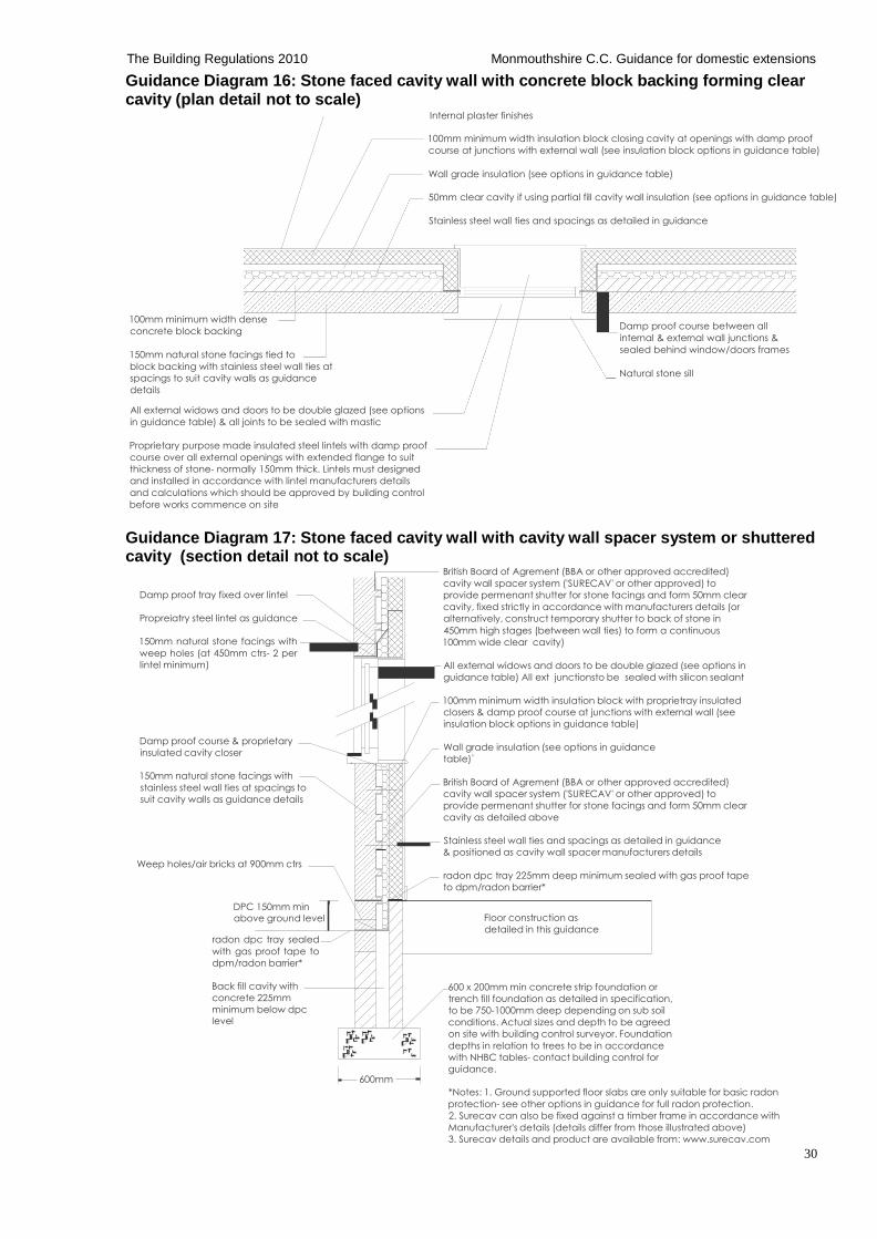
30
The Building Regulations 2010 Monmouthshire C.C. Guidance for domestic extensions
Guidance Diagram 16: Stone faced cavity wall with concrete block backing forming clear cavity (plan detail not to scale)
Internal plaster finishes
100mm minimum width insulation block closing cavity at openings with damp proof
course at junctions with external wall (see insulation block options in guidance table)
Wall grade insulation (see options in guidance table)
50mm clear cavity if using partial fill cavity wall insulation (see options in guidance table)
Stainless steel wall ties and spacings as detailed in guidance
100mm minimum width dense
concrete block backing
150mm natural stone facings tied to
block backing with stainless steel wall ties at
spacings to suit cavity walls as guidance
details
Damp proof course between all
internal & external wall junctions &
sealed behind window/doors frames
Natural stone sill
All external widows and doors to be double glazed (see options
in guidance table) & all joints to be sealed with mastic
Proprietary purpose made insulated steel lintels with damp proof
course over all external openings with extended flange to suit
thickness of stone- normally 150mm thick. Lintels must designed
and installed in accordance with lintel manufacturers details
and calculations which should be approved by building control
before works commence on site
Guidance Diagram 17: Stone faced cavity wall with cavity wall spacer system or shuttered cavity (section detail not to scale)
Damp proof tray fixed over lintel
Propreiatry steel lintel as guidance
150mm natural stone facings with
weep holes (at 450mm ctrs- 2 per
lintel minimum)
Damp proof course & proprietary
insulated cavity closer
150mm natural stone facings with
stainless steel wall ties at spacings to
suit cavity walls as guidance details
Weep holes/air bricks at 900mm ctrs
British Board of Agrement (BBA or other approved accredited)
cavity wall spacer system ('SURECAV' or other approved) to
provide permenant shutter for stone facings and form 50mm clear
cavity, fixed strictly in accordance with manufacturers details (or
alternatively, construct temporary shutter to back of stone in
450mm high stages (between wall ties) to form a continuous
100mm wide clear cavity)
All external widows and doors to be double glazed (see options in
guidance table) All ext junctionsto be sealed with silicon sealant
100mm minimum width insulation block with proprietray insulated
closers & damp proof course at junctions with external wall (see
insulation block options in guidance table)
Wall grade insulation (see options in guidance
table)`
British Board of Agrement (BBA or other approved accredited)
cavity wall spacer system ('SURECAV' or other approved) to
provide permenant shutter for stone facings and form 50mm clear
cavity as detailed above Stainless steel wall ties and spacings as detailed in guidance
& positioned as cavity wall spacer manufacturers details
radon dpc tray 225mm deep minimum sealed with gas proof tape
to dpm/radon barrier*
DPC 150mm min
above ground level
radon dpc tray sealed
with gas proof tape to
dpm/radon barrier*
Floor construction as
detailed in this guidance
Back fill cavity with
concrete 225mm
minimum below dpc
level
600mm
600 x 200mm min concrete strip foundation or
trench fill foundation as detailed in specification,
to be 750-1000mm deep depending on sub soil
conditions. Actual sizes and depth to be agreed
on site with building control surveyor. Foundation
depths in relation to trees to be in accordance
with NHBC tables- contact building control for
guidance. *Notes: 1. Ground supported floor slabs are only suitable for basic radon
protection- see other options in guidance for full radon protection.
2. Surecav can also be fixed against a timber frame in accordance with
Manufacturer's details (details differ from those illustrated above)
3. Surecav details and product are available from: www.surecav.com
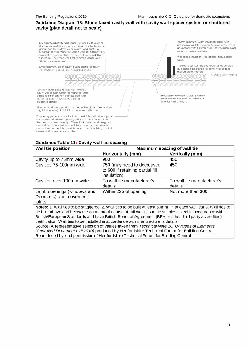
31
The Building Regulations 2010 Monmouthshire C.C. Guidance for domestic extensions
Guidance Diagram 18: Stone faced cavity wall with cavity wall spacer system or shuttered cavity (plan detail not to scale)
BBA approved cavity wall spacer system ('SURECAV' or
other approved) to provide permenant shutter for stone
facings and form 50mm clear cavity, fixed strictly in
accordance with manufacturers details (or alternatively,
construct temporary shutter to back of stone in 450mm
high stages (between wall ties) to form a continuous
100mm wide clear cavity)
50mm minimum clear cavity if using partial fill cavity
wall insulation (see options in guidance table)
100mm minimum width insulation block with
proprietray insulated closers & damp proof course
at junctions with external wall (see insulation block
options in guidance table)
Wall grade insulation (see options in guidance
table)
Stainless steel wall ties and spacings as detailed in
guidance & positioned as cavity wall spacer
manufacturers details
Internal plaster finishes
150mm natural stone facings tied through
cavity wall spacer system as manufacturers
details to inner skin with stainless steel wall
ties at spacings to suit cavity walls as
guidance details
Proprietary insulated closer & damp
proof course between all internal &
external wall junctions
All external widows and doors to be double glazed (see options
in guidance table) & all joints to be sealed with mastic
Proprietary purpose made insulated steel lintels with damp proof
course over all external openings with extended flange to suit
thickness of stone- normally 150mm thick. Lintels must designed
and installed in accordance with lintel manufacturers details
and calculations which should be approved by building control
before works commence on site
Guidance Table 11: Cavity wall tie spacing
Wall tie position Maximum spacing of wall tie
Horizontally (mm) Vertically (mm)
Cavity up to 75mm wide 900 450
Cavities 75-100mm wide 750 (may need to decreased to 600 if retaining partial fill insulation)
450
Cavities over 100mm wide To wall tie manufacturer's details
To wall tie manufacturer's details
Jamb openings (windows and Doors etc) and movement joints
Within 225 of opening Not more than 300
Notes: 1. Wall ties to be staggered. 2. Wall ties to be built at least 50mm in to each wall leaf.3. Wall ties to be built above and below the damp proof course. 4. All wall ties to be stainless steel in accordance with British/European Standards and have British Board of Agreement (BBA or other third party accredited) certification. Wall ties to be installed in accordance with manufacturer's details Source: A representative selection of values taken from Technical Note 10, U-values of Elements (Approved Document L1B2010) produced by Hertfordshire Technical Forum for Building Control. Reproduced by kind permission of Hertfordshire Technical Forum for Building Control
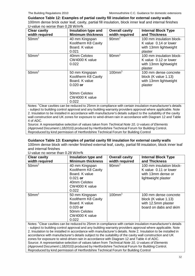
32
The Building Regulations 2010 Monmouthshire C.C. Guidance for domestic extensions
Guidance Table 12: Examples of partial cavity fill insulation for external cavity walls
100mm dense brick outer leaf, cavity, partial fill insulation, block inner leaf and internal finishes U-value no worse than 0.28 W/m²k
Clear cavity width required
Insulation type and Minimum thickness
Overall cavity width required
Internal Block Type and Thickness
50mm1 40 mm Kingspan
Kooltherm K8 Cavity Board. K value 0.021
90mm1 100 mm insulation block-
K value 0.14 or lower with 13mm lightweight plaster
50mm1 40mm Celotex
CW4000 K value 0.022
90mm1 100 mm insulation block-
K value 0.12 or lower with 13mm lightweight plaster
50mm1 50 mm Kingspan
Kooltherm K8 Cavity Board. K value 0.020 or
50mm Celotex CW4000 K value 0.022
100mm1 100 mm dense concrete
block (K value 1.13) with 13mm lightweight plaster
Notes: 1Clear cavities can be reduced to 25mm in compliance with certain insulation manufacturer's details
- subject to building control approval and any building warranty providers approval where applicable. Note 2. Insulation to be installed in accordance with manufacturer's details subject to the suitability of the cavity wall construction and UK zones for exposure to wind-driven rain in accordance with Diagram 12 and Table 4 of ADC. Source: A representative selection of values taken from Technical Note 10, U-values of Elements (Approved Document L1B2010) produced by Hertfordshire Technical Forum for Building Control.
Reproduced by kind permission of Hertfordshire Technical Forum for Building Control
Guidance Table 13: Examples of partial cavity fill insulation for external cavity walls 100mm dense block with render finished external leaf, cavity, partial fill insulation, block inner leaf and internal finishes U-value no worse than 0.28 W/m²k
Clear cavity width required
Insulation type and Minimum thickness
Overall cavity width required
Internal Block Type and Thickness
50mm1 40 mm Kingspan
Kooltherm K8 Cavity Board. K value 0.021 or 40mm Celotex CW4000 K value 0.022
90mm1 100 mm insulation block-
K value 0.11 or lower with 13mm dense or lightweight plaster
50mm1 50 mm Kingspan
Kooltherm K8 Cavity Board. K value 0.020 or 50mm Celotex CW4000 K value 0.022
100mm1 100 mm dense concrete
block (K value 1.13) with 12.5mm plaster board on dabs and skim
Notes: 1Clear cavities can be reduced to 25mm in compliance with certain insulation manufacturer's details
- subject to building control approval and any building warranty providers approval where applicable. Note 2. Insulation to be installed in accordance with manufacturer’s details. Note 2. Insulation to be installed in accordance with manufacturer's details subject to the suitability of the cavity wall construction and UK zones for exposure to wind-driven rain in accordance with Diagram 12 and Table 4 of ADC. Source: A representative selection of values taken from Technical Note 10, U-values of Elements (Approved Document L1B2010) produced by Hertfordshire Technical Forum for Building Control. Reproduced by kind permission of Hertfordshire Technical Forum for Building Control
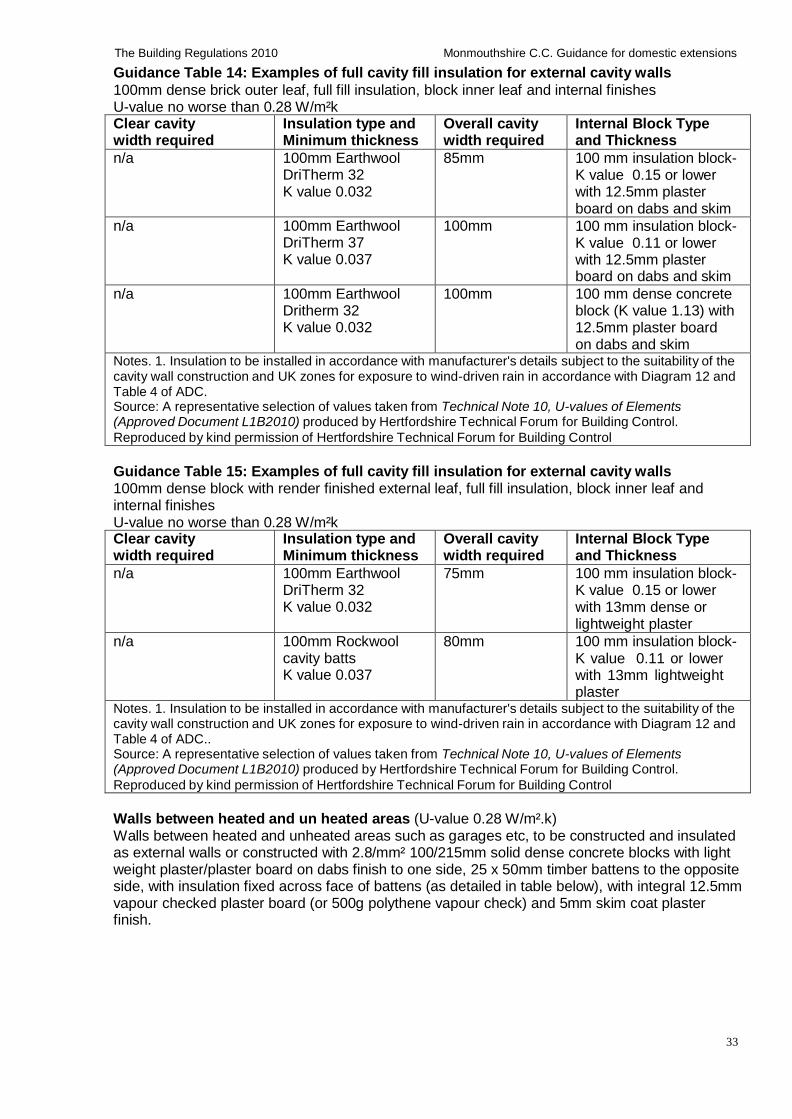
33
The Building Regulations 2010 Monmouthshire C.C. Guidance for domestic extensions
Guidance Table 14: Examples of full cavity fill insulation for external cavity walls
100mm dense brick outer leaf, full fill insulation, block inner leaf and internal finishes U-value no worse than 0.28 W/m²k
Clear cavity width required
Insulation type and Minimum thickness
Overall cavity width required
Internal Block Type and Thickness
n/a 100mm Earthwool DriTherm 32 K value 0.032
85mm 100 mm insulation block- K value 0.15 or lower with 12.5mm plaster board on dabs and skim
n/a 100mm Earthwool DriTherm 37 K value 0.037
100mm 100 mm insulation block- K value 0.11 or lower with 12.5mm plaster board on dabs and skim
n/a 100mm Earthwool Dritherm 32 K value 0.032
100mm 100 mm dense concrete block (K value 1.13) with 12.5mm plaster board on dabs and skim
Notes. 1. Insulation to be installed in accordance with manufacturer's details subject to the suitability of the cavity wall construction and UK zones for exposure to wind-driven rain in accordance with Diagram 12 and Table 4 of ADC. Source: A representative selection of values taken from Technical Note 10, U-values of Elements (Approved Document L1B2010) produced by Hertfordshire Technical Forum for Building Control.
Reproduced by kind permission of Hertfordshire Technical Forum for Building Control
Guidance Table 15: Examples of full cavity fill insulation for external cavity walls 100mm dense block with render finished external leaf, full fill insulation, block inner leaf and internal finishes U-value no worse than 0.28 W/m²k Clear cavity width required
Insulation type and Minimum thickness
Overall cavity width required
Internal Block Type and Thickness
n/a 100mm Earthwool DriTherm 32 K value 0.032
75mm 100 mm insulation block- K value 0.15 or lower with 13mm dense or lightweight plaster
n/a 100mm Rockwool cavity batts K value 0.037
80mm 100 mm insulation block- K value 0.11 or lower with 13mm lightweight plaster
Notes. 1. Insulation to be installed in accordance with manufacturer's details subject to the suitability of the cavity wall construction and UK zones for exposure to wind-driven rain in accordance with Diagram 12 and Table 4 of ADC.. Source: A representative selection of values taken from Technical Note 10, U-values of Elements (Approved Document L1B2010) produced by Hertfordshire Technical Forum for Building Control.
Reproduced by kind permission of Hertfordshire Technical Forum for Building Control
Walls between heated and un heated areas (U-value 0.28 W/m².k) Walls between heated and unheated areas such as garages etc, to be constructed and insulated as external walls or constructed with 2.8/mm² 100/215mm solid dense concrete blocks with light weight plaster/plaster board on dabs finish to one side, 25 x 50mm timber battens to the opposite side, with insulation fixed across face of battens (as detailed in table below), with integral 12.5mm vapour checked plaster board (or 500g polythene vapour check) and 5mm skim coat plaster finish.
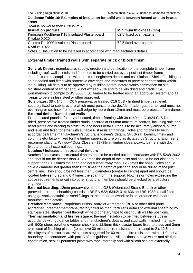
34
The Building Regulations 2010 Monmouthshire C.C. Guidance for domestic extensions
Guidance Table 16: Examples of insulation for solid walls between heated and un-heated areas
U-value no worse than 0.28 W/m²k Insulation product Minimum thickness (mm)
Kingspan Kooltherm K18 Insulated Plasterboard K value 0.020
62.5 fixed over battens
Celotex PL 4000 Insulated Plasterboard K value 0.022
72.5 fixed over battens
Notes. 1. Insulation to be installed in accordance with manufacturer’s details.
External timber framed walls with separate brick or block finish
General: Design, manufacture, supply, erection and certification of the complete timber frame including roof, walls, lintels and floors etc to be carried out by a specialist timber frame manufacturer in compliance with structural engineers details and calculations. Shell of building to be air sealed and fitted with protective coverings and measures to prevent condensation within the building. All details to be approved by building control before works commence on site. Moisture content of timber should not exceed 20% and to be kiln dried and grade C24, workmanship to comply to BS 8000:5. All timber to be treated using an approved system and all fixings to be stainless steel or other approved. Sole plates: 38 x 140mm CCA preservative treated C16 CLS kiln dried timber, set level, securely fixed to sub structure which must puncture the dpc/dpm/radon gas barrier and must not overhang or set back from the wall edge by more than 12mm and must be protected from damp. External timber framed stud walls Prefabricated panels - factory fabricated, timber framing with 38 x140mm C16/24 CLS kiln dried, preservative treated timber studs, secured at 600mm maximum centres, including sole and head plates and bracing to structural engineers details. Panels to be accurately aligned, plumb and level and fixed together with suitable rust resistant fixings. Holes and notches to be in accordance frame manufacturer's/structural engineer's details. Structural beams, lintels and columns etc- factory fixed for the timber superstructure only as dictated by Structural Engineer’s recommendations. Window/ Door Closers - 38x89mm timber closers/cavity barriers with dpc fixed around all external openings. Notches / holes/cuts in structural timbers Notches / holes/cuts in structural timbers should be carried out in accordance with BS 5268-2002 and should not be deeper than 0.125 times the depth of the joists and should be not closer to the support than 0.07 times the span and not further away than 0.25 times the span. Holes should have a diameter not greater than 0.25 times the depth of joist and should be drilled at the joist centre line. They should be not less than 3 diameters (centre to centre) apart and should be located between 0.25 and 0.4 times the span from the support. Notches or holes exceeding the above requirements or cut into other structural members should be checked by a structural engineer. External boarding: 12mm preservative treated OSB (Orientated Strand Board) or other pproved structural sheathing boards to BS EN 622; 634:2; 314; 636 and BS 1982:1, nail fixed using galvanized/stainless steel fixings to the timber studwork or in accordance with board manufacturer's details. Breather Membrane: Proprietary British Board of Agreement (BBA or other third party accredited) breather membrane, factory fixed as manufacturer's details to external sheathing by stainless steel staples fixed through white proprietary tape to distinguish wall tie positions. Thermal insulation and fire resistance: thermal insulation to be fitted between studs in accordance with guidance tables and manufacturer's details, and stud walls finished internally with 500g sheet polythene vapour check and 12.5mm thick plaster board fixed to studs and 3mm skim coat of finishing plaster (to achieve 30 minutes fire resistance- increased to 2 x 12.5mm thick layers of plaster board with joints staggered for 60 minutes fire resistance within 1.0m of a boundary in accordance with part B of this guidance) . All junctions to have water and air tight construction, seal all perimeter joints with tape internally and with silicon sealant externally.
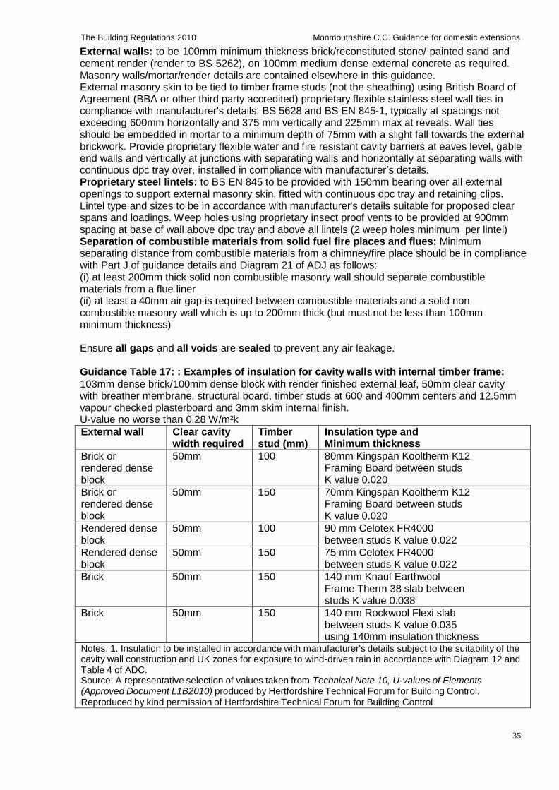
35
The Building Regulations 2010 Monmouthshire C.C. Guidance for domestic extensions
External walls: to be 100mm minimum thickness brick/reconstituted stone/ painted sand and cement render (render to BS 5262), on 100mm medium dense external concrete as required. Masonry walls/mortar/render details are contained elsewhere in this guidance. External masonry skin to be tied to timber frame studs (not the sheathing) using British Board of Agreement (BBA or other third party accredited) proprietary flexible stainless steel wall ties in compliance with manufacturer's details, BS 5628 and BS EN 845-1, typically at spacings not exceeding 600mm horizontally and 375 mm vertically and 225mm max at reveals. Wall ties should be embedded in mortar to a minimum depth of 75mm with a slight fall towards the external brickwork. Provide proprietary flexible water and fire resistant cavity barriers at eaves level, gable end walls and vertically at junctions with separating walls and horizontally at separating walls with continuous dpc tray over, installed in compliance with manufacturer’s details. Proprietary steel lintels: to BS EN 845 to be provided with 150mm bearing over all external openings to support external masonry skin, fitted with continuous dpc tray and retaining clips. Lintel type and sizes to be in accordance with manufacturer's details suitable for proposed clear spans and loadings. Weep holes using proprietary insect proof vents to be provided at 900mm spacing at base of wall above dpc tray and above all lintels (2 weep holes minimum per lintel) Separation of combustible materials from solid fuel fire places and flues: Minimum separating distance from combustible materials from a chimney/fire place should be in compliance with Part J of guidance details and Diagram 21 of ADJ as follows: (i) at least 200mm thick solid non combustible masonry wall should separate combustible materials from a flue liner (ii) at least a 40mm air gap is required between combustible materials and a solid non combustible masonry wall which is up to 200mm thick (but must not be less than 100mm minimum thickness)
Ensure all gaps and all voids are sealed to prevent any air leakage.
Guidance Table 17: : Examples of insulation for cavity walls with internal timber frame:
103mm dense brick/100mm dense block with render finished external leaf, 50mm clear cavity with breather membrane, structural board, timber studs at 600 and 400mm centers and 12.5mm vapour checked plasterboard and 3mm skim internal finish. U-value no worse than 0.28 W/m²k
External wall Clear cavity width required
Timber stud (mm)
Insulation type and Minimum thickness
Brick or rendered dense block
50mm 100 80mm Kingspan Kooltherm K12 Framing Board between studs K value 0.020
Brick or rendered dense block
50mm 150 70mm Kingspan Kooltherm K12 Framing Board between studs K value 0.020
Rendered dense block
50mm 100 90 mm Celotex FR4000 between studs K value 0.022
Rendered dense block
50mm 150 75 mm Celotex FR4000 between studs K value 0.022
Brick 50mm 150 140 mm Knauf Earthwool Frame Therm 38 slab between studs K value 0.038
Brick 50mm 150 140 mm Rockwool Flexi slab between studs K value 0.035 using 140mm insulation thickness
Notes. 1. Insulation to be installed in accordance with manufacturer's details subject to the suitability of the cavity wall construction and UK zones for exposure to wind-driven rain in accordance with Diagram 12 and Table 4 of ADC. Source: A representative selection of values taken from Technical Note 10, U-values of Elements (Approved Document L1B2010) produced by Hertfordshire Technical Forum for Building Control.
Reproduced by kind permission of Hertfordshire Technical Forum for Building Control
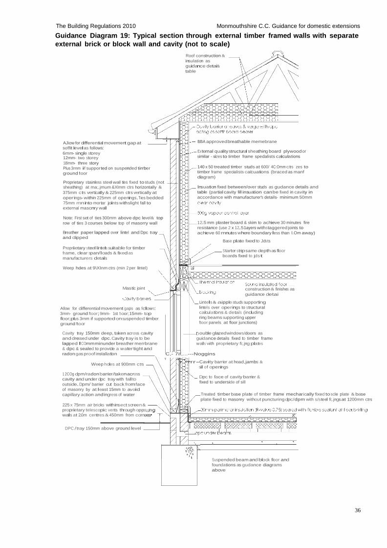
36
The Building Regulations 2010 Monmouthshire C.C. Guidance for domestic extensions
Guidance Diagram 19: Typical section through external timber framed walls with separate
external brick or block wall and cavity (not to scale)
Roof construction &
insulation as
guidance detai&
table
AJiow for differential movement gap at
soffit levelas follows:
6mm- single s torey 12mm- two s torey
18mm- three story
Plus 3rnm if supported on suspended tirrber
ground ft oor
Proprietary s tainless steel wall ties fixed to studs (not sheathing) at ma;.jmum &Xlmm ctrs horizontally &
375mm ctrs vertically & 225mm ctrs vertically at
operings- within 225mm of openings.Ties bedded
75mm mn into mortar joints withslight fall to
external mascnry wall
BBA approved breathable memebrane External quality structural sheathing board plywood or
similar - sizes to timber frame spedalists calculations
140 x 50 treated timber studs at 600/ 4C:Omm ctrs zes to
timber frame specialists calcuations (braced as manf
diagram)
lnsuation fixed between/over studs as gudance details and
table (partial cavity fill insuation can be fixed in cavity in
accordance with manufacturer's details- minimum 50mm
Note: First set of ties 300mm above dpc level& top
row of ties 3 courses below top of masorry wall
Breather paper lapped over lintel and Dpc tray
and clipped
Proprietary s teel lintels suitable for timber
frame, clear span/loads & fixed as
manufacturers details
12.5 mm plaster board & skim to achieve 30 minutes fire
resistance (use 2 x 12.51ayers withs taggered joints to
achieve 60 mnutes where boundary less than l.Om away)
Base plate fixed to Jds ts
Starter strip same depth as floor
boards fixed to jdst
Weep hdes at 9\Xlnm ctrs (min 2 per lintel)
Mastic joint
Allow for differential movement gaps as fdlow s:
3mm- ground ftoor; 9mm- 1st ft oor;15mm- top
floor;plus 3rnm if supported onsuspended timber
ground ftoor
construction & finishes as
guidance detai
Lintels & aipple studs supporting
lintels over operings to structural
calculations & details (including
ring beams supporting upper
ftoor panels at floor junctions)
Cavity tray 150mm deep, taken across cavity
and dressed under dpc. Cavity tray is to be
lapped lCOmmminunder breather merrbrane
& dpc & sealed to provide a water tight and
radon gas proof installation
Weep holes at 900mm ctrs
1 2COg dpm/radon barrier/takenacross
cavity and under dpc tray with fall to
outside. Dpm/ barrier cut back from face
of masonry by at least 15mm to avoid
capillary action and ingress of water
225 x 75mm air bricks withinsect screen &
proprietary telescopic vents through oppo ng
walls at 2.0m centres & 450mm from corners•
DPC / tray 150mm above ground level
ouble glazed windows/doors as
guidance details fixed to timber frame
walls with proprietary fi;.jng plates
C,- 7if,...---Noggins
rr.-rrr-Cavity barrier at head,jambs &
sill of openings
Dpc to face of cavity barrier &
fixed to underside of sill
Treated tirrber base plate of timber frame mecharically fixed to scle plate & base
plate fixed to masonry without puncturing dpc/dpm with s/steel fi;.jngs at 1200mm ctrs
Suspended beam and block floor and
foundations as gudance diagrams
above
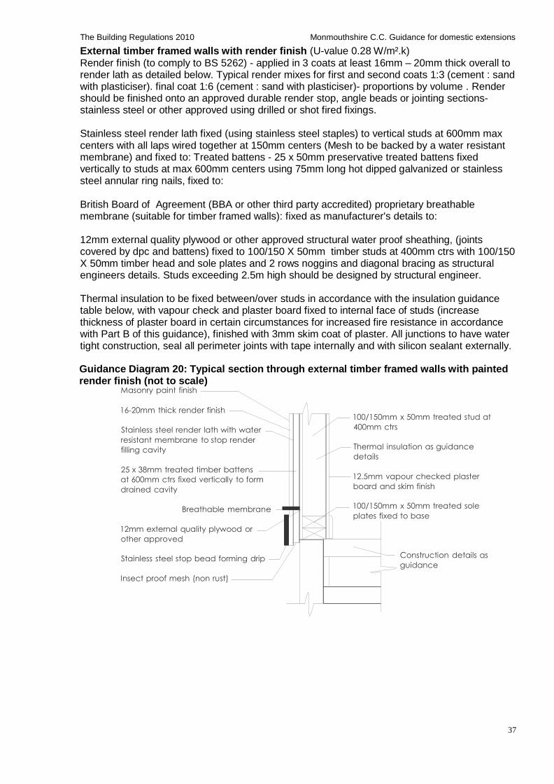
37
The Building Regulations 2010 Monmouthshire C.C. Guidance for domestic extensions
External timber framed walls with render finish (U-value 0.28 W/m².k)
Render finish (to comply to BS 5262) - applied in 3 coats at least 16mm – 20mm thick overall to render lath as detailed below. Typical render mixes for first and second coats 1:3 (cement : sand with plasticiser). final coat 1:6 (cement : sand with plasticiser)- proportions by volume . Render should be finished onto an approved durable render stop, angle beads or jointing sections- stainless steel or other approved using drilled or shot fired fixings.
Stainless steel render lath fixed (using stainless steel staples) to vertical studs at 600mm max centers with all laps wired together at 150mm centers (Mesh to be backed by a water resistant membrane) and fixed to: Treated battens - 25 x 50mm preservative treated battens fixed vertically to studs at max 600mm centers using 75mm long hot dipped galvanized or stainless steel annular ring nails, fixed to:
British Board of Agreement (BBA or other third party accredited) proprietary breathable membrane (suitable for timber framed walls): fixed as manufacturer's details to:
12mm external quality plywood or other approved structural water proof sheathing, (joints covered by dpc and battens) fixed to 100/150 X 50mm timber studs at 400mm ctrs with 100/150 X 50mm timber head and sole plates and 2 rows noggins and diagonal bracing as structural engineers details. Studs exceeding 2.5m high should be designed by structural engineer.
Thermal insulation to be fixed between/over studs in accordance with the insulation guidance table below, with vapour check and plaster board fixed to internal face of studs (increase thickness of plaster board in certain circumstances for increased fire resistance in accordance with Part B of this guidance), finished with 3mm skim coat of plaster. All junctions to have water tight construction, seal all perimeter joints with tape internally and with silicon sealant externally.
Guidance Diagram 20: Typical section through external timber framed walls with painted render finish (not to scale)
Masonry paint finish
16-20mm thick render finish
Stainless steel render lath with water
resistant membrane to stop render
filling cavity
25 x 38mm treated timber battens
at 600mm ctrs fixed vertically to form
drained cavity
Breathable membrane
12mm external quality plywood or
other approved
Stainless steel stop bead forming drip
Insect proof mesh (non rust)
100/150mm x 50mm treated stud at
400mm ctrs
Thermal insulation as guidance
details
12.5mm vapour checked plaster
board and skim finish
100/150mm x 50mm treated sole
plates fixed to base
Construction details as
guidance
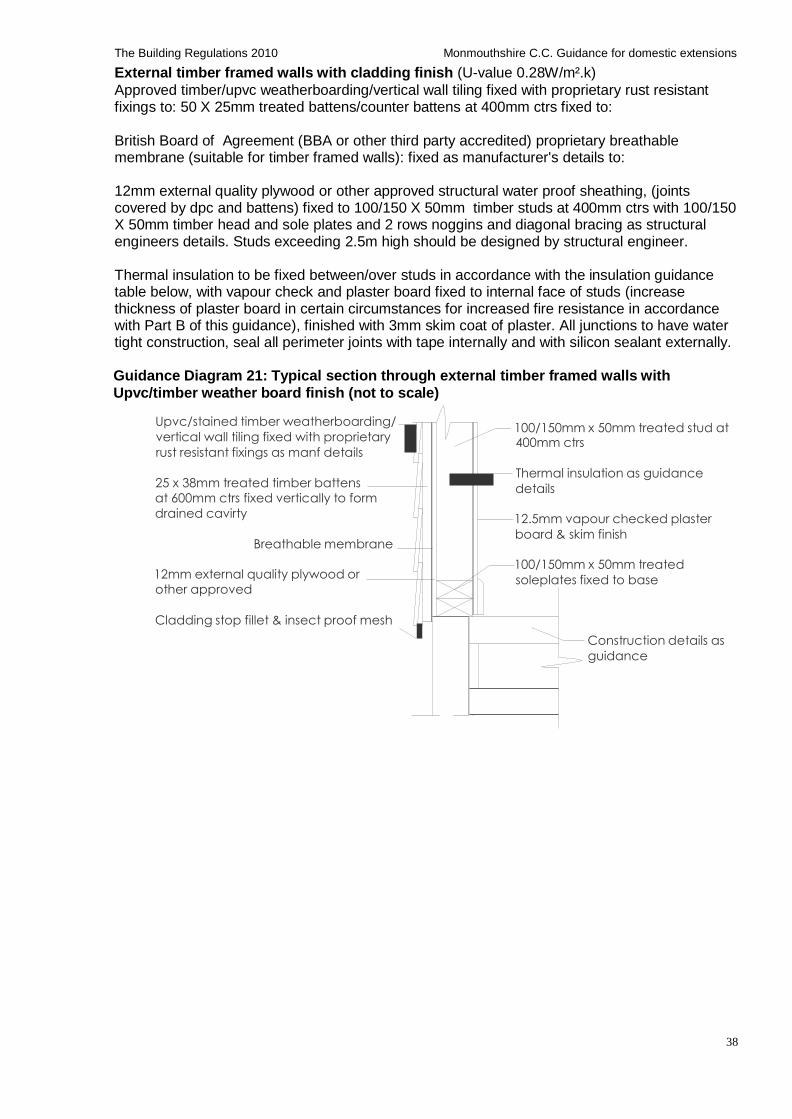
38
The Building Regulations 2010 Monmouthshire C.C. Guidance for domestic extensions
External timber framed walls with cladding finish (U-value 0.28W/m².k)
Approved timber/upvc weatherboarding/vertical wall tiling fixed with proprietary rust resistant fixings to: 50 X 25mm treated battens/counter battens at 400mm ctrs fixed to:
British Board of Agreement (BBA or other third party accredited) proprietary breathable membrane (suitable for timber framed walls): fixed as manufacturer's details to:
12mm external quality plywood or other approved structural water proof sheathing, (joints covered by dpc and battens) fixed to 100/150 X 50mm timber studs at 400mm ctrs with 100/150 X 50mm timber head and sole plates and 2 rows noggins and diagonal bracing as structural engineers details. Studs exceeding 2.5m high should be designed by structural engineer.
Thermal insulation to be fixed between/over studs in accordance with the insulation guidance table below, with vapour check and plaster board fixed to internal face of studs (increase thickness of plaster board in certain circumstances for increased fire resistance in accordance with Part B of this guidance), finished with 3mm skim coat of plaster. All junctions to have water tight construction, seal all perimeter joints with tape internally and with silicon sealant externally.
Guidance Diagram 21: Typical section through external timber framed walls with
Upvc/timber weather board finish (not to scale)
Upvc/stained timber weatherboarding/
vertical wall tiling fixed with proprietary
rust resistant fixings as manf details
25 x 38mm treated timber battens
at 600mm ctrs fixed vertically to form
drained cavirty
Breathable membrane
12mm external quality plywood or
other approved
Cladding stop fillet & insect proof mesh
100/150mm x 50mm treated stud at 400mm ctrs
Thermal insulation as guidance
details 12.5mm vapour checked plaster
board & skim finish 100/150mm x 50mm treated
soleplates fixed to base
Construction details as
guidance
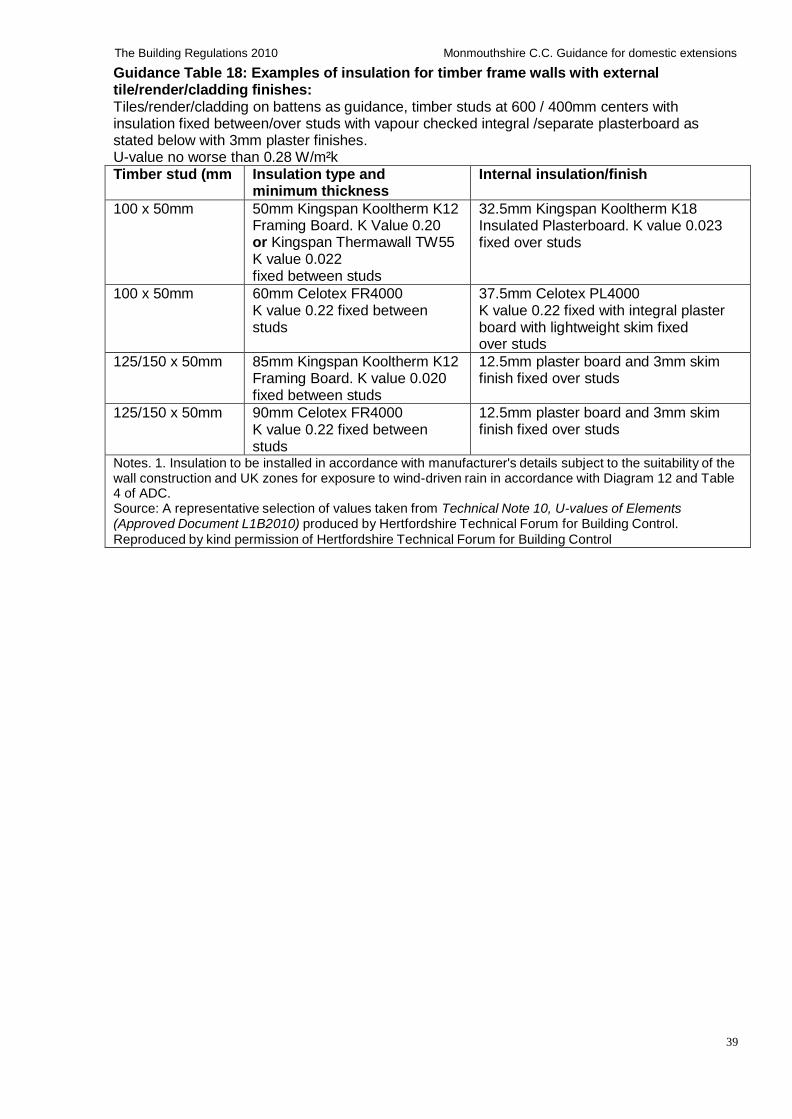
39
The Building Regulations 2010 Monmouthshire C.C. Guidance for domestic extensions
Guidance Table 18: Examples of insulation for timber frame walls with external tile/render/cladding finishes: Tiles/render/cladding on battens as guidance, timber studs at 600 / 400mm centers with insulation fixed between/over studs with vapour checked integral /separate plasterboard as stated below with 3mm plaster finishes. U-value no worse than 0.28 W/m²k Timber stud (mm Insulation type and
minimum thickness Internal insulation/finish
100 x 50mm 50mm Kingspan Kooltherm K12 Framing Board. K Value 0.20 or Kingspan Thermawall TW55 K value 0.022 fixed between studs
32.5mm Kingspan Kooltherm K18 Insulated Plasterboard. K value 0.023 fixed over studs
100 x 50mm 60mm Celotex FR4000 K value 0.22 fixed between studs
37.5mm Celotex PL4000 K value 0.22 fixed with integral plaster board with lightweight skim fixed over studs
125/150 x 50mm 85mm Kingspan Kooltherm K12 Framing Board. K value 0.020 fixed between studs
12.5mm plaster board and 3mm skim finish fixed over studs
125/150 x 50mm 90mm Celotex FR4000 K value 0.22 fixed between studs
12.5mm plaster board and 3mm skim finish fixed over studs
Notes. 1. Insulation to be installed in accordance with manufacturer's details subject to the suitability of the wall construction and UK zones for exposure to wind-driven rain in accordance with Diagram 12 and Table 4 of ADC. Source: A representative selection of values taken from Technical Note 10, U-values of Elements (Approved Document L1B2010) produced by Hertfordshire Technical Forum for Building Control.
Reproduced by kind permission of Hertfordshire Technical Forum for Building Control
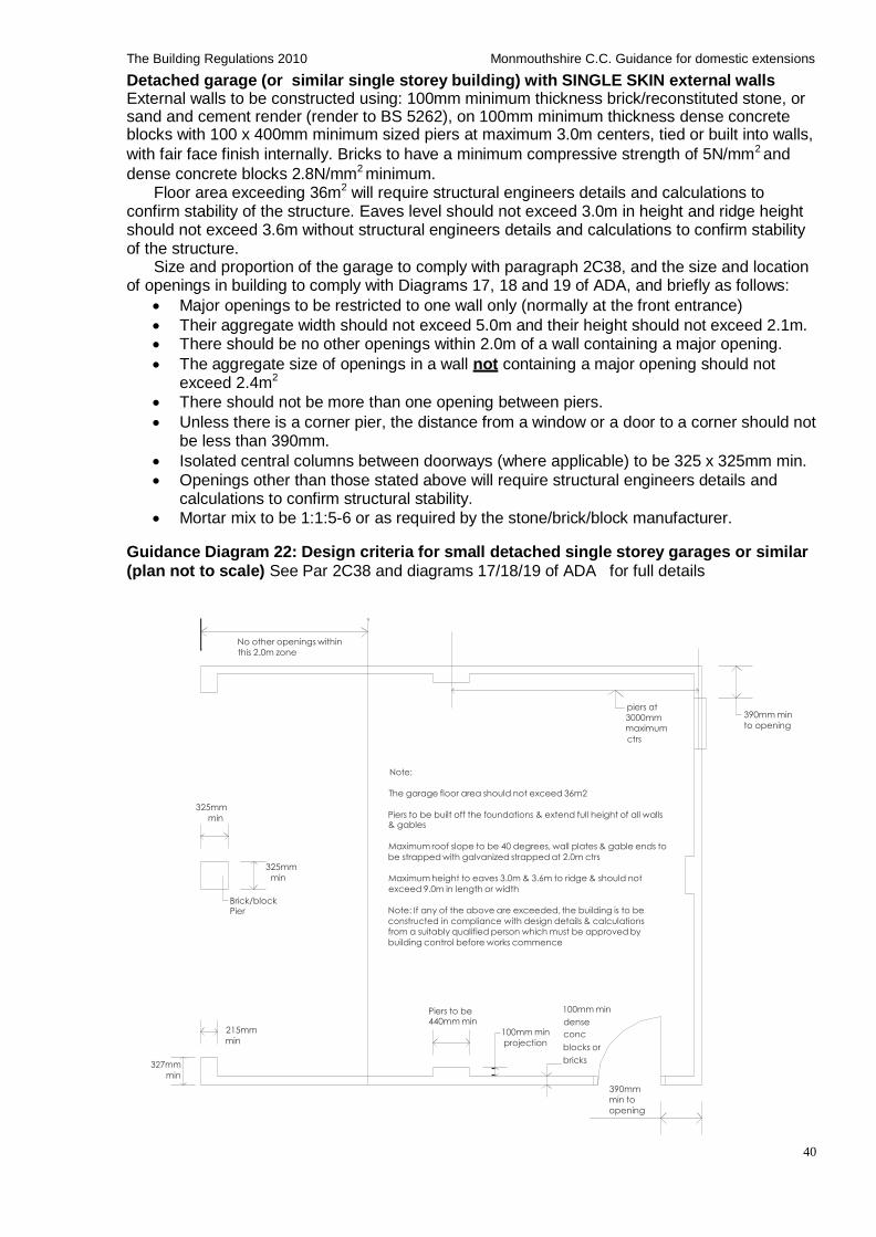
40
The Building Regulations 2010 Monmouthshire C.C. Guidance for domestic extensions
Detached garage (or similar single storey building) with SINGLE SKIN external walls External walls to be constructed using: 100mm minimum thickness brick/reconstituted stone, or sand and cement render (render to BS 5262), on 100mm minimum thickness dense concrete blocks with 100 x 400mm minimum sized piers at maximum 3.0m centers, tied or built into walls,
with fair face finish internally. Bricks to have a minimum compressive strength of 5N/mm2 and
dense concrete blocks 2.8N/mm2 minimum. Floor area exceeding 36m2 will require structural engineers details and calculations to
confirm stability of the structure. Eaves level should not exceed 3.0m in height and ridge height should not exceed 3.6m without structural engineers details and calculations to confirm stability of the structure.
Size and proportion of the garage to comply with paragraph 2C38, and the size and location of openings in building to comply with Diagrams 17, 18 and 19 of ADA, and briefly as follows:
Major openings to be restricted to one wall only (normally at the front entrance)
Their aggregate width should not exceed 5.0m and their height should not exceed 2.1m.
There should be no other openings within 2.0m of a wall containing a major opening.
The aggregate size of openings in a wall not containing a major opening should not exceed 2.4m2
There should not be more than one opening between piers.
Unless there is a corner pier, the distance from a window or a door to a corner should not be less than 390mm.
Isolated central columns between doorways (where applicable) to be 325 x 325mm min.
Openings other than those stated above will require structural engineers details and calculations to confirm structural stability.
Mortar mix to be 1:1:5-6 or as required by the stone/brick/block manufacturer. Guidance Diagram 22: Design criteria for small detached single storey garages or similar
(plan not to scale) See Par 2C38 and diagrams 17/18/19 of ADA for full details
No other openings within
this 2.0m zone
piers at
3000mm
maximum
ctrs
390mm min
to opening
Note:
325mm
min
325mm
min
Brick/block Pier
The garage floor area should not exceed 36m2 Piers to be built off the foundations & extend full height of all walls & gables
Maximum roof slope to be 40 degrees, wall plates & gable ends to
be strapped with galvanized strapped at 2.0m ctrs
Maximum height to eaves 3.0m & 3.6m to ridge & should not
exceed 9.0m in length or width
Note: If any of the above are exceeded, the building is to be
constructed in compliance with design details & calculations
from a suitably qualified person which must be approved by
building control before works commence
327mm
min
215mm
min
Piers to be 440mm min
100mm min
projection
100mm min
dense
conc
blocks or
bricks
390mm
min to
opening
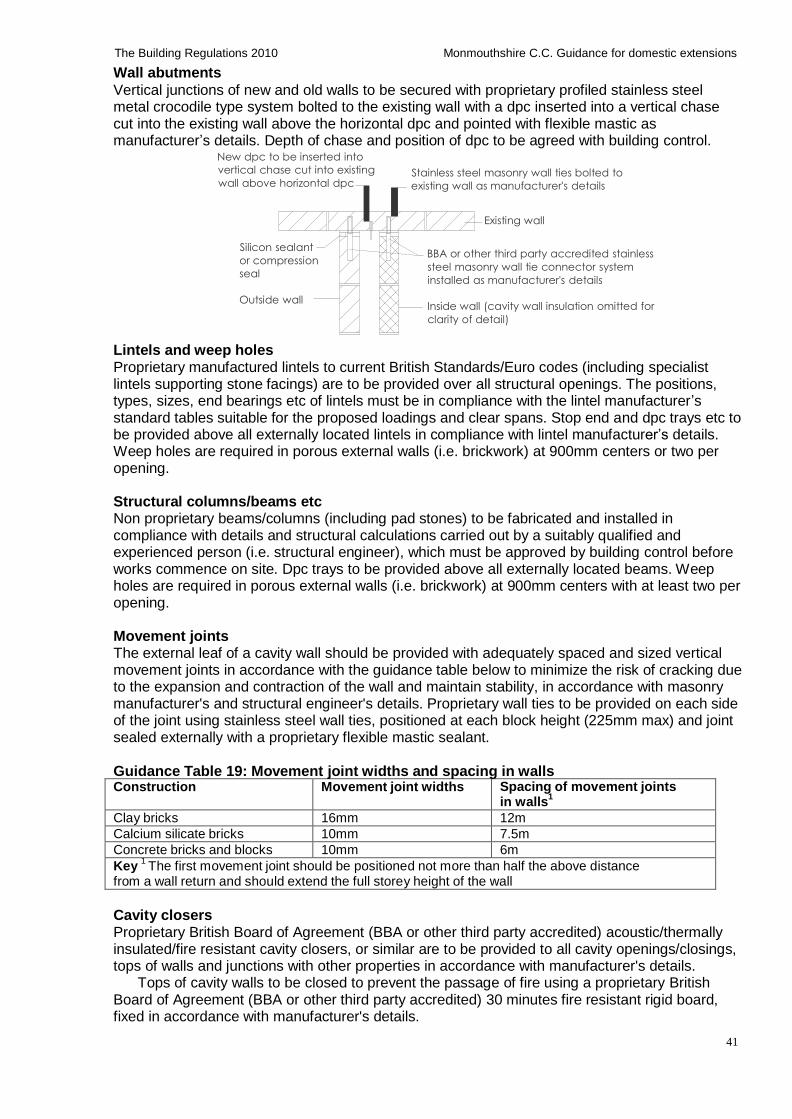
41
The Building Regulations 2010 Monmouthshire C.C. Guidance for domestic extensions
Wall abutments
Vertical junctions of new and old walls to be secured with proprietary profiled stainless steel metal crocodile type system bolted to the existing wall with a dpc inserted into a vertical chase cut into the existing wall above the horizontal dpc and pointed with flexible mastic as manufacturer’s details. Depth of chase and position of dpc to be agreed with building control.
New dpc to be inserted into
vertical chase cut into existing
wall above horizontal dpc Stainless steel masonry wall ties bolted to
existing wall as manufacturer's details
Silicon sealant
or compression
seal
Outside wall
Existing wall
BBA or other third party accredited stainless
steel masonry wall tie connector system
installed as manufacturer's details
Inside wall (cavity wall insulation omitted for
clarity of detail)
Lintels and weep holes Proprietary manufactured lintels to current British Standards/Euro codes (including specialist lintels supporting stone facings) are to be provided over all structural openings. The positions, types, sizes, end bearings etc of lintels must be in compliance with the lintel manufacturer’s standard tables suitable for the proposed loadings and clear spans. Stop end and dpc trays etc to be provided above all externally located lintels in compliance with lintel manufacturer’s details. Weep holes are required in porous external walls (i.e. brickwork) at 900mm centers or two per opening.
Structural columns/beams etc Non proprietary beams/columns (including pad stones) to be fabricated and installed in compliance with details and structural calculations carried out by a suitably qualified and experienced person (i.e. structural engineer), which must be approved by building control before works commence on site. Dpc trays to be provided above all externally located beams. Weep holes are required in porous external walls (i.e. brickwork) at 900mm centers with at least two per opening.
Movement joints The external leaf of a cavity wall should be provided with adequately spaced and sized vertical movement joints in accordance with the guidance table below to minimize the risk of cracking due to the expansion and contraction of the wall and maintain stability, in accordance with masonry manufacturer's and structural engineer's details. Proprietary wall ties to be provided on each side of the joint using stainless steel wall ties, positioned at each block height (225mm max) and joint sealed externally with a proprietary flexible mastic sealant.
Guidance Table 19: Movement joint widths and spacing in walls Construction Movement joint widths Spacing of movement joints
in walls1
Clay bricks 16mm 12m
Calcium silicate bricks 10mm 7.5m
Concrete bricks and blocks 10mm 6m
Key 1 The first movement joint should be positioned not more than half the above distance
from a wall return and should extend the full storey height of the wall
Cavity closers Proprietary British Board of Agreement (BBA or other third party accredited) acoustic/thermally insulated/fire resistant cavity closers, or similar are to be provided to all cavity openings/closings, tops of walls and junctions with other properties in accordance with manufacturer's details.
Tops of cavity walls to be closed to prevent the passage of fire using a proprietary British Board of Agreement (BBA or other third party accredited) 30 minutes fire resistant rigid board, fixed in accordance with manufacturer's details.
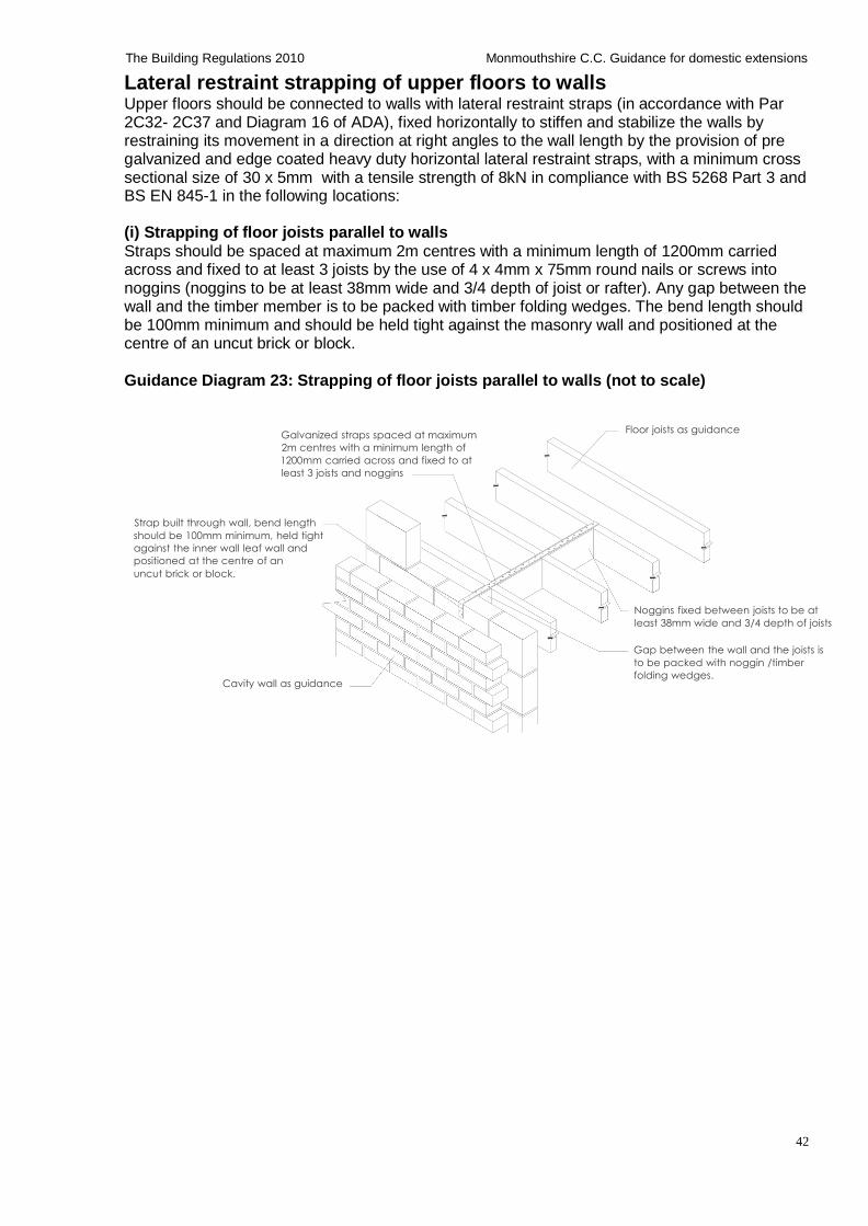
42
The Building Regulations 2010 Monmouthshire C.C. Guidance for domestic extensions
Lateral restraint strapping of upper floors to walls Upper floors should be connected to walls with lateral restraint straps (in accordance with Par 2C32- 2C37 and Diagram 16 of ADA), fixed horizontally to stiffen and stabilize the walls by restraining its movement in a direction at right angles to the wall length by the provision of pre galvanized and edge coated heavy duty horizontal lateral restraint straps, with a minimum cross sectional size of 30 x 5mm with a tensile strength of 8kN in compliance with BS 5268 Part 3 and BS EN 845-1 in the following locations:
(i) Strapping of floor joists parallel to walls
Straps should be spaced at maximum 2m centres with a minimum length of 1200mm carried across and fixed to at least 3 joists by the use of 4 x 4mm x 75mm round nails or screws into noggins (noggins to be at least 38mm wide and 3/4 depth of joist or rafter). Any gap between the wall and the timber member is to be packed with timber folding wedges. The bend length should be 100mm minimum and should be held tight against the masonry wall and positioned at the centre of an uncut brick or block.
Guidance Diagram 23: Strapping of floor joists parallel to walls (not to scale)
Galvanized straps spaced at maximum
2m centres with a minimum length of
1200mm carried across and fixed to at
least 3 joists and noggins
Floor joists as guidance
Strap built through wall, bend length
should be 100mm minimum, held tight
against the inner wall leaf wall and
positioned at the centre of an
uncut brick or block.
Noggins fixed between joists to be at
least 38mm wide and 3/4 depth of joists
Cavity wall as guidance
Gap between the wall and the joists is
to be packed with noggin /timber
folding wedges.
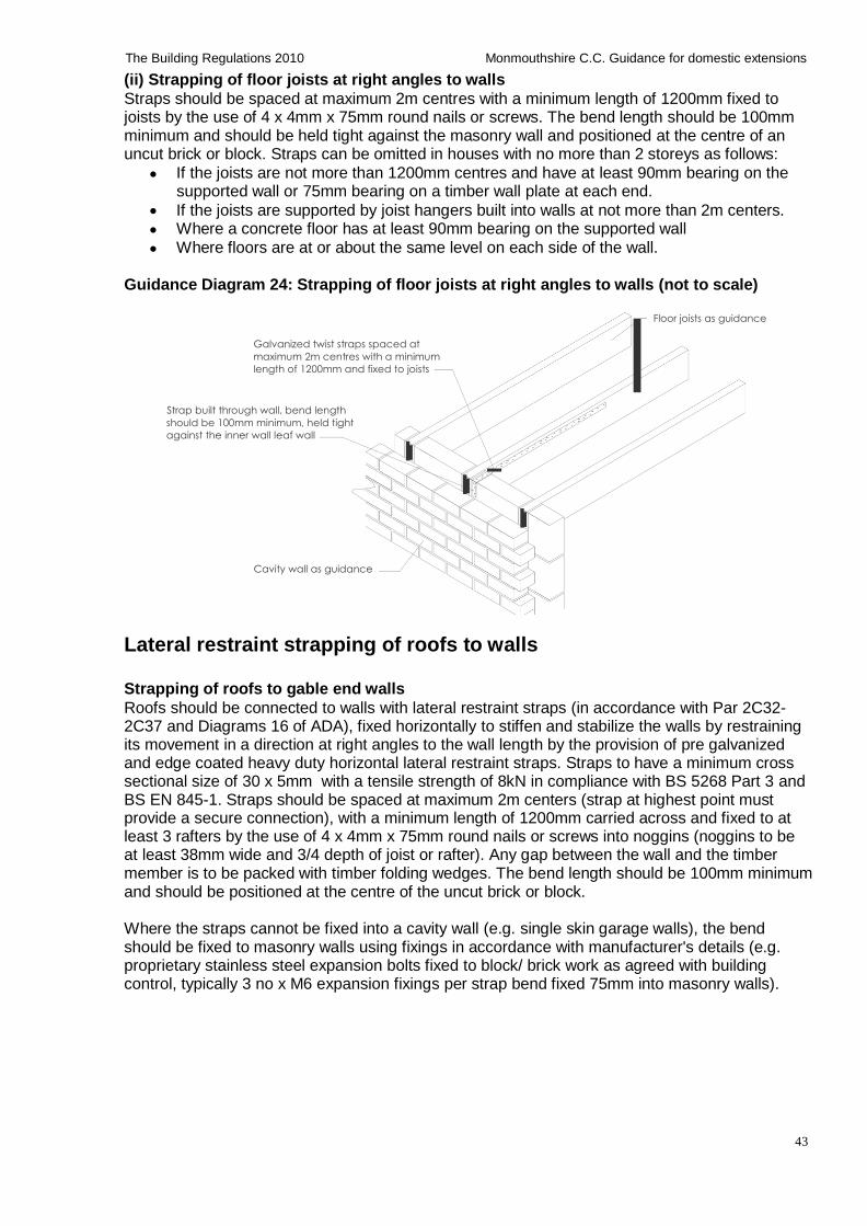
43
The Building Regulations 2010 Monmouthshire C.C. Guidance for domestic extensions
(ii) Strapping of floor joists at right angles to walls
Straps should be spaced at maximum 2m centres with a minimum length of 1200mm fixed to joists by the use of 4 x 4mm x 75mm round nails or screws. The bend length should be 100mm minimum and should be held tight against the masonry wall and positioned at the centre of an uncut brick or block. Straps can be omitted in houses with no more than 2 storeys as follows:
If the joists are not more than 1200mm centres and have at least 90mm bearing on the supported wall or 75mm bearing on a timber wall plate at each end.
If the joists are supported by joist hangers built into walls at not more than 2m centers.
Where a concrete floor has at least 90mm bearing on the supported wall
Where floors are at or about the same level on each side of the wall. Guidance Diagram 24: Strapping of floor joists at right angles to walls (not to scale)
Floor joists as guidance
Galvanized twist straps spaced at
maximum 2m centres with a minimum
length of 1200mm and fixed to joists
Strap built through wall, bend length
should be 100mm minimum, held tight
against the inner wall leaf wall
Cavity wall as guidance
Lateral restraint strapping of roofs to walls
Strapping of roofs to gable end walls
Roofs should be connected to walls with lateral restraint straps (in accordance with Par 2C32- 2C37 and Diagrams 16 of ADA), fixed horizontally to stiffen and stabilize the walls by restraining its movement in a direction at right angles to the wall length by the provision of pre galvanized and edge coated heavy duty horizontal lateral restraint straps. Straps to have a minimum cross sectional size of 30 x 5mm with a tensile strength of 8kN in compliance with BS 5268 Part 3 and BS EN 845-1. Straps should be spaced at maximum 2m centers (strap at highest point must provide a secure connection), with a minimum length of 1200mm carried across and fixed to at least 3 rafters by the use of 4 x 4mm x 75mm round nails or screws into noggins (noggins to be at least 38mm wide and 3/4 depth of joist or rafter). Any gap between the wall and the timber member is to be packed with timber folding wedges. The bend length should be 100mm minimum and should be positioned at the centre of the uncut brick or block.
Where the straps cannot be fixed into a cavity wall (e.g. single skin garage walls), the bend should be fixed to masonry walls using fixings in accordance with manufacturer's details (e.g. proprietary stainless steel expansion bolts fixed to block/ brick work as agreed with building control, typically 3 no x M6 expansion fixings per strap bend fixed 75mm into masonry walls).
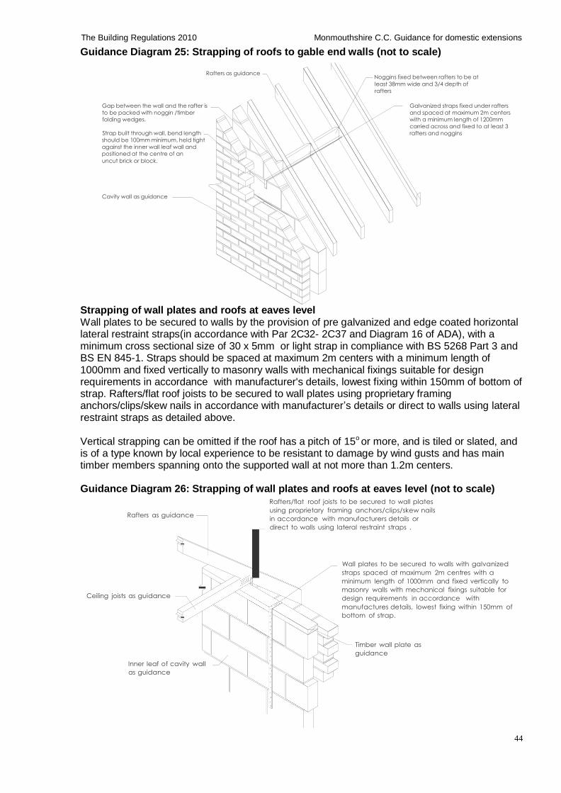
44
The Building Regulations 2010 Monmouthshire C.C. Guidance for domestic extensions
Guidance Diagram 25: Strapping of roofs to gable end walls (not to scale)
Rafters as guidance Noggins fixed between rafters to be at
least 38mm wide and 3/4 depth of
rafters
Gap between the wall and the rafter is
to be packed with noggin /timber
folding wedges.
Strap built through wall, bend length
should be 100mm minimum, held tight
against the inner wall leaf wall and
positioned at the centre of an
uncut brick or block.
Galvanized straps fixed under rafters
and spaced at maximum 2m centers
with a minimum length of 1200mm
carried across and fixed to at least 3
rafters and noggins
Cavity wall as guidance
Strapping of wall plates and roofs at eaves level Wall plates to be secured to walls by the provision of pre galvanized and edge coated horizontal lateral restraint straps(in accordance with Par 2C32- 2C37 and Diagram 16 of ADA), with a minimum cross sectional size of 30 x 5mm or light strap in compliance with BS 5268 Part 3 and BS EN 845-1. Straps should be spaced at maximum 2m centers with a minimum length of 1000mm and fixed vertically to masonry walls with mechanical fixings suitable for design requirements in accordance with manufacturer's details, lowest fixing within 150mm of bottom of strap. Rafters/flat roof joists to be secured to wall plates using proprietary framing anchors/clips/skew nails in accordance with manufacturer’s details or direct to walls using lateral restraint straps as detailed above.
Vertical strapping can be omitted if the roof has a pitch of 15o or more, and is tiled or slated, and is of a type known by local experience to be resistant to damage by wind gusts and has main timber members spanning onto the supported wall at not more than 1.2m centers.
Guidance Diagram 26: Strapping of wall plates and roofs at eaves level (not to scale)
Rafters/flat roof joists to be secured to wall plates
using proprietary framing anchors/clips/skew nails Rafters as guidance
Ceiling joists as guidance
Inner leaf of cavity wall
as guidance
in accordance with manufacturers details or
direct to walls using lateral restraint straps .
Wall plates to be secured to walls with galvanized
straps spaced at maximum 2m centres with a
minimum length of 1000mm and fixed vertically to
masonry walls with mechanical fixings suitable for
design requirements in accordance with
manufactures details, lowest fixing within 150mm of
bottom of strap.
Timber wall plate as
guidance
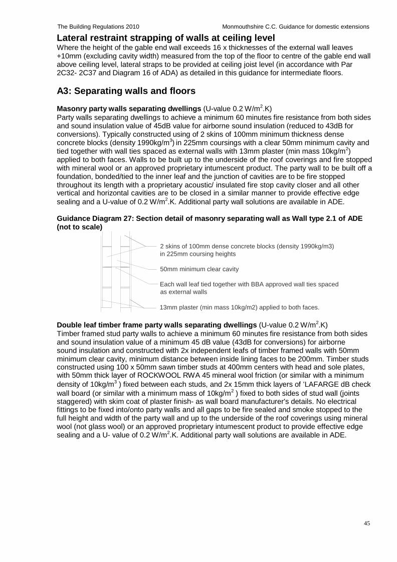
45
The Building Regulations 2010 Monmouthshire C.C. Guidance for domestic extensions
Lateral restraint strapping of walls at ceiling level Where the height of the gable end wall exceeds 16 x thicknesses of the external wall leaves +10mm (excluding cavity width) measured from the top of the floor to centre of the gable end wall above ceiling level, lateral straps to be provided at ceiling joist level (in accordance with Par 2C32- 2C37 and Diagram 16 of ADA) as detailed in this guidance for intermediate floors.
A3: Separating walls and floors Masonry party walls separating dwellings (U-value 0.2 W/m2.K)
Party walls separating dwellings to achieve a minimum 60 minutes fire resistance from both sides and sound insulation value of 45dB value for airborne sound insulation (reduced to 43dB for conversions). Typically constructed using of 2 skins of 100mm minimum thickness dense concrete blocks (density 1990kg/m3) in 225mm coursings with a clear 50mm minimum cavity and tied together with wall ties spaced as external walls with 13mm plaster (min mass 10kg/m2) applied to both faces. Walls to be built up to the underside of the roof coverings and fire stopped with mineral wool or an approved proprietary intumescent product. The party wall to be built off a foundation, bonded/tied to the inner leaf and the junction of cavities are to be fire stopped throughout its length with a proprietary acoustic/ insulated fire stop cavity closer and all other vertical and horizontal cavities are to be closed in a similar manner to provide effective edge
sealing and a U-value of 0.2 W/m2.K. Additional party wall solutions are available in ADE. Guidance Diagram 27: Section detail of masonry separating wall as Wall type 2.1 of ADE (not to scale)
2 skins of 100mm dense concrete blocks (density 1990kg/m3)
in 225mm coursing heights
50mm minimum clear cavity
Each wall leaf tied together with BBA approved wall ties spaced
as external walls
13mm plaster (min mass 10kg/m2) applied to both faces.
Double leaf timber frame party walls separating dwellings (U-value 0.2 W/m2.K)
Timber framed stud party walls to achieve a minimum 60 minutes fire resistance from both sides and sound insulation value of a minimum 45 dB value (43dB for conversions) for airborne sound insulation and constructed with 2x independent leafs of timber framed walls with 50mm minimum clear cavity, minimum distance between inside lining faces to be 200mm. Timber studs constructed using 100 x 50mm sawn timber studs at 400mm centers with head and sole plates, with 50mm thick layer of ROCKWOOL RWA 45 mineral wool friction (or similar with a minimum
density of 10kg/m3 ) fixed between each studs, and 2x 15mm thick layers of ‘LAFARGE dB check
wall board (or similar with a minimum mass of 10kg/m2 ) fixed to both sides of stud wall (joints staggered) with skim coat of plaster finish- as wall board manufacturer's details. No electrical fittings to be fixed into/onto party walls and all gaps to be fire sealed and smoke stopped to the full height and width of the party wall and up to the underside of the roof coverings using mineral wool (not glass wool) or an approved proprietary intumescent product to provide effective edge sealing and a U- value of 0.2 W/m2.K. Additional party wall solutions are available in ADE.
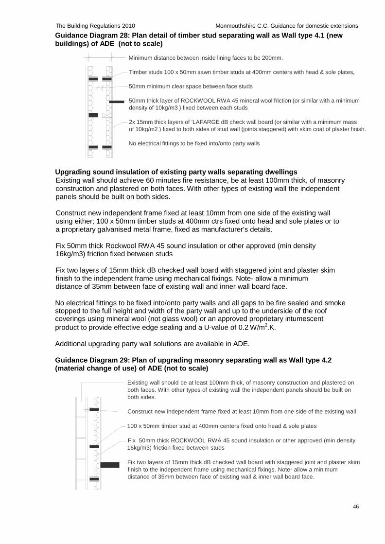
46
The Building Regulations 2010 Monmouthshire C.C. Guidance for domestic extensions
Guidance Diagram 28: Plan detail of timber stud separating wall as Wall type 4.1 (new buildings) of ADE (not to scale)
Minimum distance between inside lining faces to be 200mm.
Timber studs 100 x 50mm sawn timber studs at 400mm centers with head & sole plates,
50mm minimum clear space between face studs
50mm thick layer of ROCKWOOL RWA 45 mineral wool friction (or similar with a minimum
density of 10kg/m3 ) fixed between each studs
2x 15mm thick layers of 'LAFARGE dB check wall board (or similar with a minimum mass
of 10kg/m2 ) fixed to both sides of stud wall (joints staggered) with skim coat of plaster finish.
No electrical fittings to be fixed into/onto party walls
Upgrading sound insulation of existing party walls separating dwellings
Existing wall should achieve 60 minutes fire resistance, be at least 100mm thick, of masonry construction and plastered on both faces. With other types of existing wall the independent panels should be built on both sides.
Construct new independent frame fixed at least 10mm from one side of the existing wall using either; 100 x 50mm timber studs at 400mm ctrs fixed onto head and sole plates or to a proprietary galvanised metal frame, fixed as manufacturer's details.
Fix 50mm thick Rockwool RWA 45 sound insulation or other approved (min density 16kg/m3) friction fixed between studs
Fix two layers of 15mm thick dB checked wall board with staggered joint and plaster skim finish to the independent frame using mechanical fixings. Note- allow a minimum distance of 35mm between face of existing wall and inner wall board face.
No electrical fittings to be fixed into/onto party walls and all gaps to be fire sealed and smoke stopped to the full height and width of the party wall and up to the underside of the roof coverings using mineral wool (not glass wool) or an approved proprietary intumescent
product to provide effective edge sealing and a U-value of 0.2 W/m2.K. Additional upgrading party wall solutions are available in ADE.
Guidance Diagram 29: Plan of upgrading masonry separating wall as Wall type 4.2 (material change of use) of ADE (not to scale)
Existing wall should be at least 100mm thick, of masonry construction and plastered on
both faces. With other types of existing wall the independent panels should be built on
both sides.
Construct new independent frame fixed at least 10mm from one side of the existing wall
100 x 50mm timber stud at 400mm centers fixed onto head & sole plates
Fix 50mm thick ROCKWOOL RWA 45 sound insulation or other approved (min density
16kg/m3) friction fixed between studs
Fix two layers of 15mm thick dB checked wall board with staggered joint and plaster skim
finish to the independent frame using mechanical fixings. Note- allow a minimum
distance of 35mm between face of existing wall & inner wall board face.
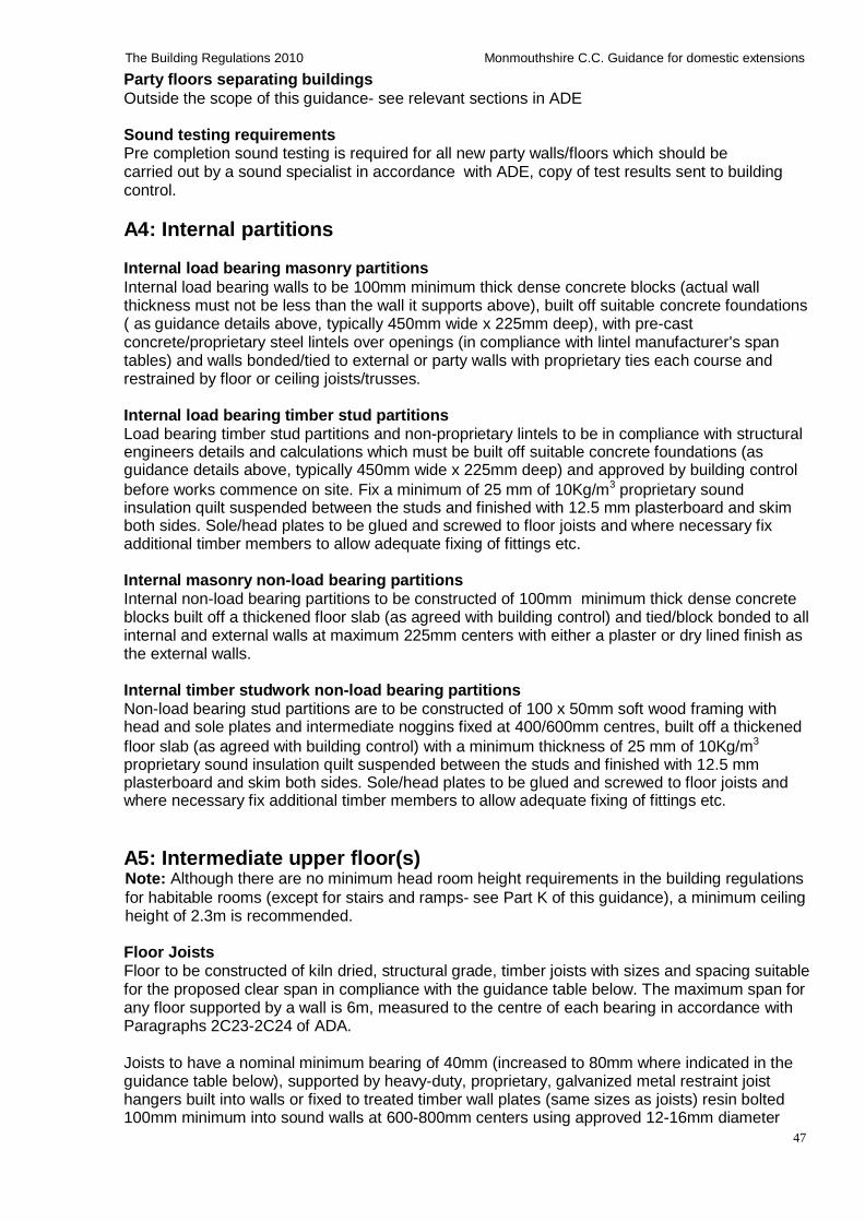
47
The Building Regulations 2010 Monmouthshire C.C. Guidance for domestic extensions
Party floors separating buildings
Outside the scope of this guidance- see relevant sections in ADE Sound testing requirements Pre completion sound testing is required for all new party walls/floors which should be carried out by a sound specialist in accordance with ADE, copy of test results sent to building control.
A4: Internal partitions Internal load bearing masonry partitions
Internal load bearing walls to be 100mm minimum thick dense concrete blocks (actual wall thickness must not be less than the wall it supports above), built off suitable concrete foundations ( as guidance details above, typically 450mm wide x 225mm deep), with pre-cast concrete/proprietary steel lintels over openings (in compliance with lintel manufacturer's span tables) and walls bonded/tied to external or party walls with proprietary ties each course and restrained by floor or ceiling joists/trusses.
Internal load bearing timber stud partitions Load bearing timber stud partitions and non-proprietary lintels to be in compliance with structural engineers details and calculations which must be built off suitable concrete foundations (as guidance details above, typically 450mm wide x 225mm deep) and approved by building control
before works commence on site. Fix a minimum of 25 mm of 10Kg/m3 proprietary sound insulation quilt suspended between the studs and finished with 12.5 mm plasterboard and skim both sides. Sole/head plates to be glued and screwed to floor joists and where necessary fix additional timber members to allow adequate fixing of fittings etc.
Internal masonry non-load bearing partitions Internal non-load bearing partitions to be constructed of 100mm minimum thick dense concrete blocks built off a thickened floor slab (as agreed with building control) and tied/block bonded to all internal and external walls at maximum 225mm centers with either a plaster or dry lined finish as the external walls.
Internal timber studwork non-load bearing partitions Non-load bearing stud partitions are to be constructed of 100 x 50mm soft wood framing with head and sole plates and intermediate noggins fixed at 400/600mm centres, built off a thickened
floor slab (as agreed with building control) with a minimum thickness of 25 mm of 10Kg/m3
proprietary sound insulation quilt suspended between the studs and finished with 12.5 mm plasterboard and skim both sides. Sole/head plates to be glued and screwed to floor joists and where necessary fix additional timber members to allow adequate fixing of fittings etc.
A5: Intermediate upper floor(s) Note: Although there are no minimum head room height requirements in the building regulations
for habitable rooms (except for stairs and ramps- see Part K of this guidance), a minimum ceiling height of 2.3m is recommended.
Floor Joists Floor to be constructed of kiln dried, structural grade, timber joists with sizes and spacing suitable for the proposed clear span in compliance with the guidance table below. The maximum span for any floor supported by a wall is 6m, measured to the centre of each bearing in accordance with Paragraphs 2C23-2C24 of ADA.
Joists to have a nominal minimum bearing of 40mm (increased to 80mm where indicated in the guidance table below), supported by heavy-duty, proprietary, galvanized metal restraint joist hangers built into walls or fixed to treated timber wall plates (same sizes as joists) resin bolted 100mm minimum into sound walls at 600-800mm centers using approved 12-16mm diameter

48
The Building Regulations 2010 Monmouthshire C.C. Guidance for domestic extensions
stainless steel fixings- as agreed with building control. Alternatively, joists can be built into walls using approved proprietary sealed joist caps or sealed with silicon sealant to provide an air tight seal for new dwellings which require air testing, as agreed with building control. Two joists are to be bolted together under baths and non load bearing partitions running parallel with joists, increased to three joists under non load bearing partitions, where indicated in guidance table. Where non load bearing partitions run at right angles to the joists, the spans in the guidance table below should be reduced by 10%.
Floor void between joists to be insulated with a minimum thickness of 100 mm of 10Kg/m³ proprietary sound insulation quilt, ceiling to be a minimum 15mm plasterboard and skim to give the required sound insulation and 30 minutes fire resistance. Floor joists to be provided with 1 row of 38 x ¾ depth solid strutting at ends between joist hangers or proprietary galvanized struts to BS EN 10327 fixed as manufacturer's details, at mid span for 2.5 – 4.5m spans and 2 rows at 1/3 centers for spans over 4.5m.
Fix 22mm thick moisture resistant tongue and grooved timber floor boards laid with joints staggered, long edge fixed across the joists and all joints positioned over joists/noggins. All boards to be glued and screwed to floor joists with all joints glued (using water proof glue) and pinned, in accordance with floor board manufacturer's details and current BS EN standards. Allow expansion gap around wall perimeters as manufacturer's details (typically 10-15mm).
Guidance Table 20: Timber sizes and spans for domestic floor joists (Strength Class C24) Supporting domestic floor loads and non load bearing timber stud partitions (imposed load not exceeding 1.5kN/m2 ; dead load (excluding self weight of joist) not more than 0.5kNm2) Size of joist Spacing of joist (mm)
400 450 600
Breadth X Depth (mm) (mm)
Maximum clear span (m)
47 97 47 120 47 145 47 170 47 195 47 220 75 220
2.10* 1.99* 1.74 2.67* 2.56* 2.31 3.21* 3.09* 2.80 3.76* 3.61* 3.28
4.30* 4.13* 3.751
4.83* 4.65*1
4.231
5.61* 5.41* 4.93*
Notes: Where non load bearing partitions run at right angles to the joists, the spans in the guidance table
should be reduced by 10%. Two joists are to be bolted together under baths and non load bearing partitions running parallel with joists.
Key *Increased to three joists bolted together under baths and non load bearing partitions running parallel with joists;
1 80mm minimum bearing required
The above values have been independently compiled for guidance table by Geomex Ltd Structural Engineers: www.geomex.co.uk
Span tables for C16 and C24 strength class solid timber members in floors, ceilings and roofs for dwellings are available from TRADA Technology at: www.trada.co.uk/bookshop
Trimming and trimmer joists
Trimming joists and trimmer joist sizes supporting trimmed joists around openings should be in accordance with the guidance tables below or calculations and details are required from a suitably qualified person (i.e. structural engineer) which should be approved by building control before works commence on site. Minimum bearing 80mm and double joists should be mechanically fixed together using at least two bolted connections at 1/3rd spacing, using 12mm diameter high tensile bolts and 3 x 50mm steel washers at each bolt end. Joists to be supported on heavy duty galvanized joist hangers to current British Standards and fixed in accordance with joist hanger manufacturer’s details. Notches / holes/cuts in structural timbers should be carried out in accordance with these guidance details and BS 5268-2002.
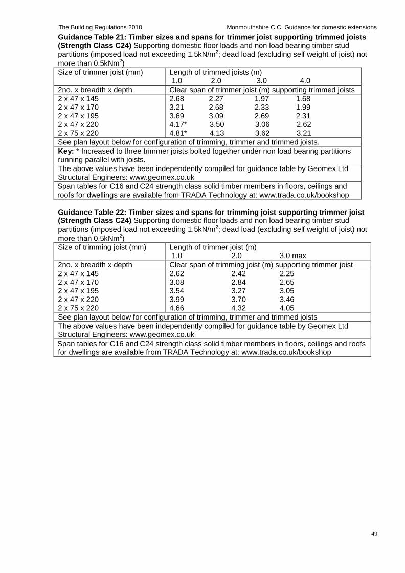
49
The Building Regulations 2010 Monmouthshire C.C. Guidance for domestic extensions
Guidance Table 21: Timber sizes and spans for trimmer joist supporting trimmed joists (Strength Class C24) Supporting domestic floor loads and non load bearing timber stud
partitions (imposed load not exceeding 1.5kN/m2; dead load (excluding self weight of joist) not
more than 0.5kNm2)
Size of trimmer joist (mm) Length of trimmed joists (m) 1.0 2.0 3.0 4.0
2no. x breadth x depth Clear span of trimmer joist (m) supporting trimmed joists
2 x 47 x 145 2 x 47 x 170 2 x 47 x 195 2 x 47 x 220 2 x 75 x 220
2.68 2.27 1.97 1.68 3.21 2.68 2.33 1.99 3.69 3.09 2.69 2.31 4.17* 3.50 3.06 2.62 4.81* 4.13 3.62 3.21
See plan layout below for configuration of trimming, trimmer and trimmed joists.
Key: * Increased to three trimmer joists bolted together under non load bearing partitions running parallel with joists.
The above values have been independently compiled for guidance table by Geomex Ltd Structural Engineers: www.geomex.co.uk
Span tables for C16 and C24 strength class solid timber members in floors, ceilings and roofs for dwellings are available from TRADA Technology at: www.trada.co.uk/bookshop
Guidance Table 22: Timber sizes and spans for trimming joist supporting trimmer joist (Strength Class C24) Supporting domestic floor loads and non load bearing timber stud
partitions (imposed load not exceeding 1.5kN/m2; dead load (excluding self weight of joist) not
more than 0.5kNm2)
Size of trimming joist (mm) Length of trimmer joist (m) 1.0 2.0 3.0 max
2no. x breadth x depth Clear span of trimming joist (m) supporting trimmer joist
2 x 47 x 145 2 x 47 x 170 2 x 47 x 195 2 x 47 x 220 2 x 75 x 220
2.62 2.42 2.25 3.08 2.84 2.65 3.54 3.27 3.05 3.99 3.70 3.46 4.66 4.32 4.05
See plan layout below for configuration of trimming, trimmer and trimmed joists
The above values have been independently compiled for guidance table by Geomex Ltd Structural Engineers: www.geomex.co.uk
Span tables for C16 and C24 strength class solid timber members in floors, ceilings and roofs for dwellings are available from TRADA Technology at: www.trada.co.uk/bookshop
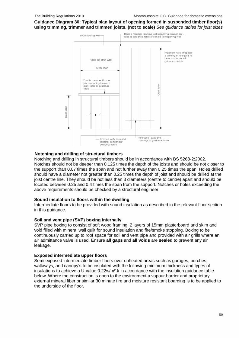
50
The Building Regulations 2010 Monmouthshire C.C. Guidance for domestic extensions
Cle
ar
Cle
ar
Guidance Diagram 30: Typical plan layout of opening formed in suspended timber floor(s)
using trimming, trimmer and trimmed joists. (not to scale) See guidance tables for joist sizes
Load bearing wall
Double member trimming joist supporting trimmer joist -
sizes as guidance table or can be a supporting wall
VOID OR STAIR WELL
Important note: strapping
& strutting of floor joists to
be accordance with
guidance details.
Clear span
Double member trimmer
joist supporting trimmed
joists - sizes as guidance
table
Trimmed joists- sizes and
spacings as floor joist
guidance table
Floor joists - sizes and
spacings as guidance table
Notching and drilling of structural timbers
Notching and drilling in structural timbers should be in accordance with BS 5268-2:2002. Notches should not be deeper than 0.125 times the depth of the joists and should be not closer to the support than 0.07 times the span and not further away than 0.25 times the span. Holes drilled should have a diameter not greater than 0.25 times the depth of joist and should be drilled at the joist centre line. They should be not less than 3 diameters (centre to centre) apart and should be located between 0.25 and 0.4 times the span from the support. Notches or holes exceeding the above requirements should be checked by a structural engineer.
Sound insulation to floors within the dwelling
Intermediate floors to be provided with sound insulation as described in the relevant floor section in this guidance.
Soil and vent pipe (SVP) boxing internally SVP pipe boxing to consist of soft wood framing, 2 layers of 15mm plasterboard and skim and void filled with mineral wall quilt for sound insulation and fire/smoke stopping. Boxing to be continuously carried up to roof space for soil and vent pipe and provided with air grills where an air admittance valve is used. Ensure all gaps and all voids are sealed to prevent any air leakage.
Exposed intermediate upper floors
Semi exposed intermediate timber floors over unheated areas such as garages, porches, walkways, and canopy’s to be insulated with the following minimum thickness and types of insulations to achieve a U-value 0.22w/m².k in accordance with the insulation guidance table below. Where the construction is open to the environment a vapour barrier and proprietary external mineral fiber or similar 30 minute fire and moisture resistant boarding is to be applied to the underside of the floor.
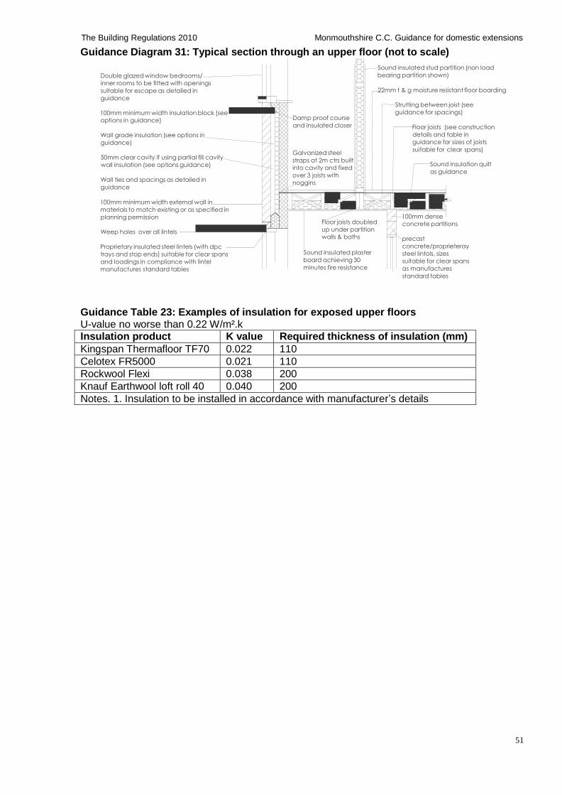
51
The Building Regulations 2010 Monmouthshire C.C. Guidance for domestic extensions
Guidance Diagram 31: Typical section through an upper floor (not to scale)
Double glazed window bedrooms/
inner rooms to be fitted with openings
suitable for escape as detailed in
guidance
100mm minimum width insulation block (see
options in guidance)
Wall grade insulation (see options in
guidance)
50mm clear cavity if using partial fill cavity
wall insulation (see options guidance)
Wall ties and spacings as detailed in
guidance
100mm minimum width external wall in
materials to match existing or as specified in
planning permission
Weep holes over all lintels
Proprietary insulated steel lintels (with dpc
trays and stop ends) suitable for clear spans
and loadings in compliance with lintel
manufactures standard tables
Damp proof course
and insulated closer
Galvanized steel
straps at 2m ctrs built
into cavity and fixed
over 3 joists with
noggins
Floor joists doubled
up under partition
walls & baths
Sound insulated plaster
board achieving 30
minutes fire resistance
Sound insulated stud partition (non load
bearing partition shown) 22mm t & g moisture resistant floor boarding
Strutting between joist (see
guidance for spacings)
Floor joists (see construction
details and table in
guidance for sizes of joists
suitable for clear spans)
Sound insulation quilt
as guidance
100mm dense
concrete partitions
precast
concrete/proprieteray
steel lintols, sizes
suitable for clear spans
as manufactures
standard tables
Guidance Table 23: Examples of insulation for exposed upper floors U-value no worse than 0.22 W/m².k Insulation product K value Required thickness of insulation (mm)
Kingspan Thermafloor TF70 0.022 110
Celotex FR5000 0.021 110
Rockwool Flexi 0.038 200
Knauf Earthwool loft roll 40 0.040 200
Notes. 1. Insulation to be installed in accordance with manufacturer’s details
52
The Building Regulations 2010 Monmouthshire C.C. Guidance for domestic extensions
A6: Pitched roofs Note: Although there are no minimum head room height requirements in the building regulations for habitable rooms (except for stairs and ramps- see Part K of this guidance), a minimum ceiling height of 2.3m is recommended.
Pitched roof coverings
Roof covering to consist of slates/tiles and associated ridge, verge, eaves, hip, valley, abutment and ventilation systems etc fitted in accordance with the tile manufacturer’s details, suitable for the minimum recommended roof pitches and exposure.
Roof tiles/cladding to be fixed in accordance with manufacturer's details to 25 x 50mm treated timber battens (battens to be at least 1.2m long, nailed to each rafter and fixed over at least three rafters and spaced in accordance with tile manufacturer's details), rafters to be overlaid with un- tearable underlay's using either a non breathable/high water vapour resistance underlay to BS EN 13707: 2004 (requires ventilation on opposing sides as detailed in guidance) or a British Board of Agreement (BBA or other third party accredited) vapour permeable breathable/low water resistance type underlay, both types to be fixed, ventilated and lapped in accordance with manufacturer's details.
Where roof coverings cannot be fixed to the tile/slate manufacturer's required pitch, roof coverings can be fixed below manufacturer's minimum recommended roof pitch by using a proprietary British Board of Agreement (BBA or other third party accredited) corrugated roof sheet system below roof coverings to create an independent secondary weatherproof roof, which must be installed to minimum roof pitches and ventilated in accordance with manufacturer's details. e.g. ’Ondutile' under tile and slate under-sheeting system manufactured by Onduline
Building Products Ltd: www.onduline.net. (Typical minimum roof pitches: 12.5o for concrete
interlocking tiles; 17.5o for clay pan tiles/ natural and fibre cement slates; 22.5o for plain double lap tiles- contact manufacturer for minimum roof pitches achievable)
Pitched roof structure Roof to be constructed using either manufactured roof trusses or a cut roof as follows:
(i) Roof trusses (including attic and girder trusses)
Roof to be constructed using specialist designed and manufactured trusses (or Attic trusses where forming room(s) in the roof or used for storage) at 400mm (or 600mm maximum) spacing's to BS 5268:3 or PD 6693-2. Trusses to be fixed and braced strictly in accordance with BS 5268:3 or PD 6693-2 and truss manufacturer's details, mechanically fixed to 100 x 50mm treated soft wood wall plates using proprietary galvanized steel truss clips. Reinforced concrete pad stones are required to support girder trusses to details and calculations by a suitably qualified person.
The person carrying out the building work is to check and confirm the actual roof pitch to the truss manufacturer prior to placing an order. Details of trusses and bracing diagram is to be prepared by the specialist designer/truss manufacturer, which must be submitted and approved by building control prior to commencing roof construction.
(ii) Cut roof construction Roof to be constructed using kiln dried –stress graded timber. Rafters, ceiling joists, purlins, hanger and binder sizes as stated in the independent guidance tables below or see TRADA Technology Span Tables available from: www.trada.co.uk, suitable for the proposed clear spans and all properly fixed together using approved mechanical fixings. Where the ceiling joists are raised above wall plate level they must be fixed within the bottom third of the rafter using 12mm diameter high tensile bolts and proprietary steel toothed connectors to connect each rafter and ceiling joist to prevent possible roof spread. Joists raised above this level are to be designed by a suitably qualified person and approved by building control before works commence.
Typical minimum sizes of roof timbers: struts and braces to be 100 X 50mm, hip sizes to be the splayed rafter depth + 25mm X 50mm thick(under 30 degree pitch the hips are to be designed by
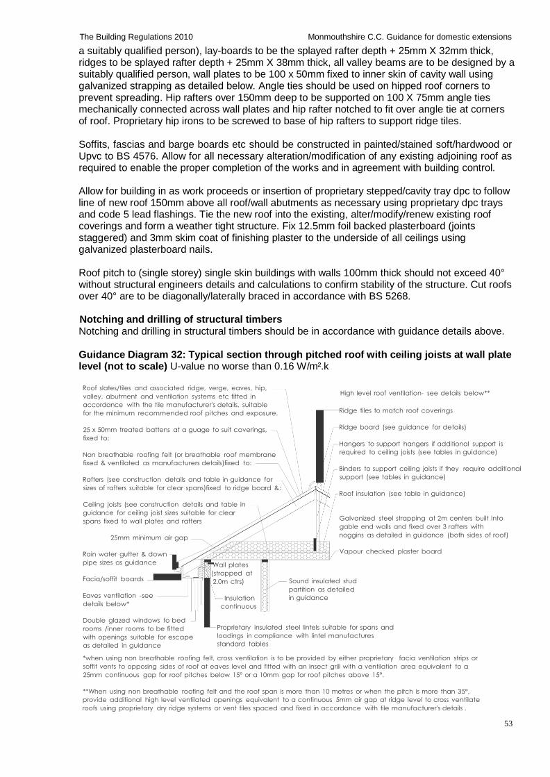
53
The Building Regulations 2010 Monmouthshire C.C. Guidance for domestic extensions
a suitably qualified person), lay-boards to be the splayed rafter depth + 25mm X 32mm thick, ridges to be splayed rafter depth + 25mm X 38mm thick, all valley beams are to be designed by a suitably qualified person, wall plates to be 100 x 50mm fixed to inner skin of cavity wall using galvanized strapping as detailed below. Angle ties should be used on hipped roof corners to prevent spreading. Hip rafters over 150mm deep to be supported on 100 X 75mm angle ties mechanically connected across wall plates and hip rafter notched to fit over angle tie at corners of roof. Proprietary hip irons to be screwed to base of hip rafters to support ridge tiles.
Soffits, fascias and barge boards etc should be constructed in painted/stained soft/hardwood or Upvc to BS 4576. Allow for all necessary alteration/modification of any existing adjoining roof as required to enable the proper completion of the works and in agreement with building control.
Allow for building in as work proceeds or insertion of proprietary stepped/cavity tray dpc to follow line of new roof 150mm above all roof/wall abutments as necessary using proprietary dpc trays and code 5 lead flashings. Tie the new roof into the existing, alter/modify/renew existing roof coverings and form a weather tight structure. Fix 12.5mm foil backed plasterboard (joints staggered) and 3mm skim coat of finishing plaster to the underside of all ceilings using galvanized plasterboard nails.
Roof pitch to (single storey) single skin buildings with walls 100mm thick should not exceed 40° without structural engineers details and calculations to confirm stability of the structure. Cut roofs over 40° are to be diagonally/laterally braced in accordance with BS 5268.
Notching and drilling of structural timbers Notching and drilling in structural timbers should be in accordance with guidance details above.
Guidance Diagram 32: Typical section through pitched roof with ceiling joists at wall plate level (not to scale) U-value no worse than 0.16 W/m².k
Roof slates/tiles and associated ridge, verge, eaves, hip,
valley, abutment and ventilation systems etc fitted in
accordance with the tile manufacturer's details, suitable
for the minimum recommended roof pitches and exposure.
25 x 50mm treated battens at a guage to suit coverings,
fixed to:
Non breathable roofing felt (or breathable roof membrane
fixed & ventilated as manufacturers details)fixed to:
Rafters (see construction details and table in guidance for
sizes of rafters suitable for clear spans)fixed to ridge board &:
Ceiling joists (see construction details and table in
guidance for ceiling joist sizes suitable for clear
spans fixed to wall plates and rafters
25mm minimum air gap
Rain water gutter & down
High level roof ventilation- see details below**
Ridge tiles to match roof coverings
Ridge board (see guidance for details)
Hangers to support hangers if additional support is
required to ceiling joists (see tables in guidance)
Binders to support ceiling joists if they require additional
support (see tables in guidance)
Roof insulation (see table in guidance) Galvanized steel strapping at 2m centers built into
gable end walls and fixed over 3 rafters with
noggins as detailed in guidance (both sides of roof)
Vapour checked plaster board
pipe sizes as guidance
Facia/soffit boards
Eaves ventilation -see
details below*
Wall plates
(strapped at
2.0m ctrs)
Insulation
continuous
Sound insulated stud
partition as detailed
in guidance
Double glazed windows to bed
rooms /inner rooms to be fitted
with openings suitable for escape
as detailed in guidance
Proprietary insulated steel lintels suitable for spans and
loadings in compliance with lintel manufactures
standard tables
*when using non breathable roofing felt, cross ventilation is to be provided by either proprietary facia ventilation strips or
soffit vents to opposing sides of roof at eaves level and fitted with an insect grill with a ventilation area equivalent to a
25mm continuous gap for roof pitches below 15° or a 10mm gap for roof pitches above 15°.
**When using non breathable roofing felt and the roof span is more than 10 metres or when the pitch is more than 35°,
provide additional high level ventilated openings equivalent to a continuous 5mm air gap at ridge level to cross ventilate
roofs using proprietary dry ridge systems or vent tiles spaced and fixed in accordance with tile manufacturer's details .
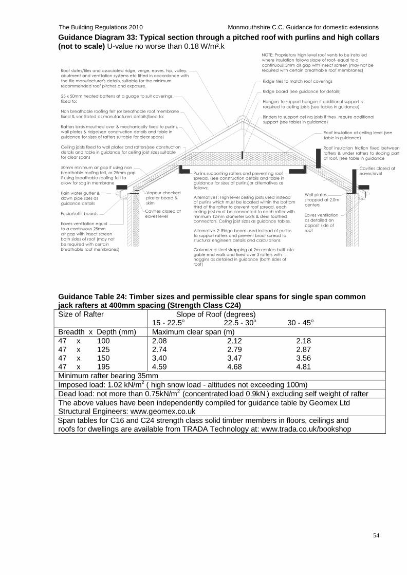
54
The Building Regulations 2010 Monmouthshire C.C. Guidance for domestic extensions
Guidance Diagram 33: Typical section through a pitched roof with purlins and high collars
(not to scale) U-value no worse than 0.18 W/m².k
Roof slates/tiles and associated ridge, verge, eaves, hip, valley,
abutment and ventilation systems etc fitted in accordance with
the tile manufacturer's details, suitable for the minimum
recommended roof pitches and exposure.
25 x 50mm treated battens at a guage to suit coverings,
fixed to:
Non breathable roofing felt (or breathable roof membrane
fixed & ventilated as manufacturers details)fixed to:
Rafters birds mouthed over & mechanically fixed to purlins,
wall plates & ridge(see construction details and table in
guidance for sizes of rafters suitable for clear spans)
Ceiling joists fixed to wall plates and rafters(see construction
details and table in guidance for ceiling joist sizes suitable
for clear spans
NOTE: Proprietary high level roof vents to be installed
where insulation follows slope of roof- equal to a
continuous 5mm air gap with insect screen (may not be
required with certain breathable roof membranes)
Ridge tiles to match roof coverings
Ridge board (see guidance for details)
Hangers to support hangers if additional support is
required to ceiling joists (see tables in guidance)
Binders to support ceiling joists if they require additional
support (see tables in guidance)
Roof insulation at ceiling level (see
table in guidance)
Roof insulation friction fixed between
rafters & under rafters to sloping part
of roof. (see table in guidance
50mm minimum air gap if using non
breathable roofing felt, or 25mm gap
if using breathable roofing felt to
allow for sag in membrane
Rain water gutter &
down pipe sizes as
guidance details
Facia/soffit boards
Eaves ventilation equal
to a continuous 25mm
air gap with insect screen
both sides of roof (may not
be required with certain
breathable roof membranes)
Vapour checked
plaster board &
skim
Cavities closed at
eaves level
Purlins supporting rafters and preventing roof spread. (see construction details and table in guidance for sizes of purlins)or alternatives as follows:. Alternative1: High level ceiling joists used instead of purlins which must be located within the bottom third of the rafter to prevent roof spread, each ceiling joist must be connected to each rafter with minmum 12mm diameter bolts & steel toothed connectors. Celing joist sizes as guidance tables. Alternative 2: Ridge beam used instead of purlins to support rafters and prevent broof spread to stuctural engineers details and calculations Galvanized steel strapping at 2m centers built into gable end walls and fixed over 3 rafters with noggins as detailed in guidance (both sides of roof)
Wall plates
strapped at 2.0m
centers
Eaves ventilation
as detailed on
opposit side of
roof
Cavities closed at
eaves level
Guidance Table 24: Timber sizes and permissible clear spans for single span common jack rafters at 400mm spacing (Strength Class C24)
Size of Rafter Slope of Roof (degrees) 15 - 22.5o 22.5 - 30o 30 - 45o
Breadth x Depth (mm) Maximum clear span (m)
47 x 100 47 x 125 47 x 150 47 x 195
2.08 2.12 2.18 2.74 2.79 2.87 3.40 3.47 3.56 4.59 4.68 4.81
Minimum rafter bearing 35mm
Imposed load: 1.02 kN/m2 ( high snow load - altitudes not exceeding 100m)
Dead load: not more than 0.75kN/m2 (concentrated load 0.9kN ) excluding self weight of rafter
The above values have been independently compiled for guidance table by Geomex Ltd Structural Engineers: www.geomex.co.uk
Span tables for C16 and C24 strength class solid timber members in floors, ceilings and roofs for dwellings are available from TRADA Technology at: www.trada.co.uk/bookshop
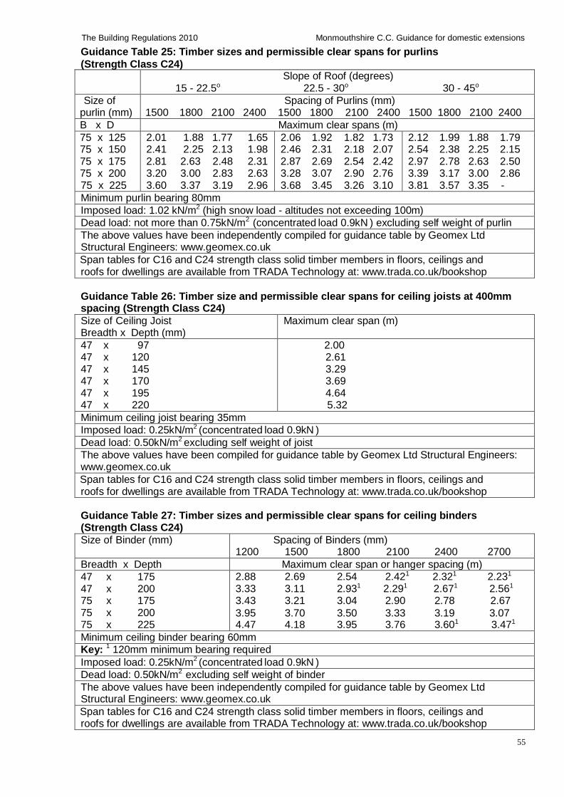
55
The Building Regulations 2010 Monmouthshire C.C. Guidance for domestic extensions
Guidance Table 25: Timber sizes and permissible clear spans for purlins
(Strength Class C24)
Slope of Roof (degrees) 15 - 22.5o 22.5 - 30o 30 - 45o
Size of purlin (mm)
Spacing of Purlins (mm) 1500 1800 2100 2400 1500 1800 2100 2400 1500 1800 2100 2400
B x D Maximum clear spans (m)
75 x 125 75 x 150 75 x 175 75 x 200 75 x 225
2.01 1.88 1.77 1.65 2.41 2.25 2.13 1.98 2.81 2.63 2.48 2.31 3.20 3.00 2.83 2.63 3.60 3.37 3.19 2.96
2.06 1.92 1.82 1.73 2.46 2.31 2.18 2.07 2.87 2.69 2.54 2.42 3.28 3.07 2.90 2.76 3.68 3.45 3.26 3.10
2.12 1.99 1.88 1.79 2.54 2.38 2.25 2.15 2.97 2.78 2.63 2.50 3.39 3.17 3.00 2.86 3.81 3.57 3.35 -
Minimum purlin bearing 80mm
Imposed load: 1.02 kN/m2 (high snow load - altitudes not exceeding 100m)
Dead load: not more than 0.75kN/m2 (concentrated load 0.9kN ) excluding self weight of purlin
The above values have been independently compiled for guidance table by Geomex Ltd Structural Engineers: www.geomex.co.uk
Span tables for C16 and C24 strength class solid timber members in floors, ceilings and roofs for dwellings are available from TRADA Technology at: www.trada.co.uk/bookshop
Guidance Table 26: Timber size and permissible clear spans for ceiling joists at 400mm spacing (Strength Class C24)
Size of Ceiling Joist Breadth x Depth (mm)
Maximum clear span (m)
47 x 97 47 x 120 47 x 145 47 x 170 47 x 195 47 x 220
2.00 2.61 3.29 3.69 4.64 5.32
Minimum ceiling joist bearing 35mm
Imposed load: 0.25kN/m2 (concentrated load 0.9kN )
Dead load: 0.50kN/m2 excluding self weight of joist
The above values have been compiled for guidance table by Geomex Ltd Structural Engineers: www.geomex.co.uk
Span tables for C16 and C24 strength class solid timber members in floors, ceilings and roofs for dwellings are available from TRADA Technology at: www.trada.co.uk/bookshop
Guidance Table 27: Timber sizes and permissible clear spans for ceiling binders (Strength Class C24)
Size of Binder (mm) Spacing of Binders (mm) 1200 1500 1800 2100 2400 2700
Breadth x Depth Maximum clear span or hanger spacing (m)
47 x 175 47 x 200 75 x 175 75 x 200 75 x 225
2.88 2.69 2.54 2.421 2.321 2.231
3.33 3.11 2.931 2.291 2.671 2.561
3.43 3.21 3.04 2.90 2.78 2.67
3.95 3.70 3.50 3.33 3.19 3.07 4.47 4.18 3.95 3.76 3.601 3.471
Minimum ceiling binder bearing 60mm
Key: 1 120mm minimum bearing required
Imposed load: 0.25kN/m2 (concentrated load 0.9kN )
Dead load: 0.50kN/m2 excluding self weight of binder
The above values have been independently compiled for guidance table by Geomex Ltd Structural Engineers: www.geomex.co.uk
Span tables for C16 and C24 strength class solid timber members in floors, ceilings and roofs for dwellings are available from TRADA Technology at: www.trada.co.uk/bookshop
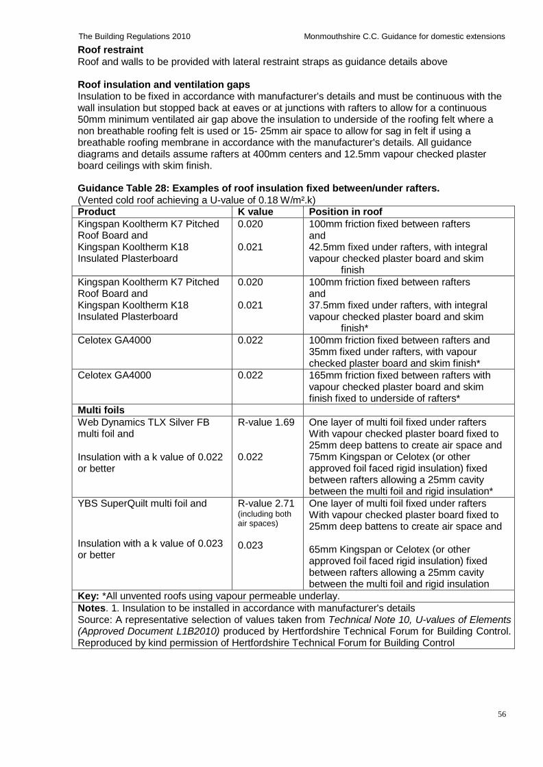
56
The Building Regulations 2010 Monmouthshire C.C. Guidance for domestic extensions
Roof restraint
Roof and walls to be provided with lateral restraint straps as guidance details above
Roof insulation and ventilation gaps Insulation to be fixed in accordance with manufacturer's details and must be continuous with the wall insulation but stopped back at eaves or at junctions with rafters to allow for a continuous 50mm minimum ventilated air gap above the insulation to underside of the roofing felt where a non breathable roofing felt is used or 15- 25mm air space to allow for sag in felt if using a breathable roofing membrane in accordance with the manufacturer's details. All guidance diagrams and details assume rafters at 400mm centers and 12.5mm vapour checked plaster board ceilings with skim finish.
Guidance Table 28: Examples of roof insulation fixed between/under rafters.
(Vented cold roof achieving a U-value of 0.18 W/m².k) Product K value Position in roof
Kingspan Kooltherm K7 Pitched Roof Board and Kingspan Kooltherm K18 Insulated Plasterboard
0.020 0.021
100mm friction fixed between rafters and 42.5mm fixed under rafters, with integral vapour checked plaster board and skim
finish
Kingspan Kooltherm K7 Pitched Roof Board and Kingspan Kooltherm K18 Insulated Plasterboard
0.020 0.021
100mm friction fixed between rafters and 37.5mm fixed under rafters, with integral vapour checked plaster board and skim
finish*
Celotex GA4000 0.022 100mm friction fixed between rafters and 35mm fixed under rafters, with vapour checked plaster board and skim finish*
Celotex GA4000 0.022 165mm friction fixed between rafters with vapour checked plaster board and skim finish fixed to underside of rafters*
Multi foils Web Dynamics TLX Silver FB multi foil and
Insulation with a k value of 0.022 or better
R-value 1.69
0.022
One layer of multi foil fixed under rafters With vapour checked plaster board fixed to 25mm deep battens to create air space and 75mm Kingspan or Celotex (or other approved foil faced rigid insulation) fixed between rafters allowing a 25mm cavity between the multi foil and rigid insulation*
YBS SuperQuilt multi foil and Insulation with a k value of 0.023 or better
R-value 2.71 (including both air spaces)
0.023
One layer of multi foil fixed under rafters With vapour checked plaster board fixed to 25mm deep battens to create air space and
65mm Kingspan or Celotex (or other approved foil faced rigid insulation) fixed between rafters allowing a 25mm cavity between the multi foil and rigid insulation
Key: *All unvented roofs using vapour permeable underlay.
Notes. 1. Insulation to be installed in accordance with manufacturer's details Source: A representative selection of values taken from Technical Note 10, U-values of Elements (Approved Document L1B2010) produced by Hertfordshire Technical Forum for Building Control. Reproduced by kind permission of Hertfordshire Technical Forum for Building Control
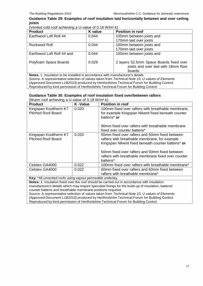
57
The Building Regulations 2010 Monmouthshire C.C. Guidance for domestic extensions
Guidance Table 29: Examples of roof insulation laid horizontally between and over ceiling joists
(Vented cold roof achieving a U-value of 0.16 W/m².k) Product K value Position in roof
Earthwool Loft Roll 44 0.044 100mm between joists and 170mm laid over joists
Rockwool Roll 0.044 100mm between joists and 170mm laid over joists
Earthwool Loft Roll 44 and Polyfoam Space Boards
0.044 0.029
100mm between joists and 2 layers 52.5mm Space Boards fixed over
joists and over laid with 18mm floor boards
Notes. 1. Insulation to be installed in accordance with manufacturer's details Source: A representative selection of values taken from Technical Note 10, U-values of Elements (Approved Document L1B2010) produced by Hertfordshire Technical Forum for Building Control.
Reproduced by kind permission of Hertfordshire Technical Forum for Building Control
Guidance Table 30: Examples of roof insulation fixed over/between rafters
(Warm roof achieving a U-value of 0.18 W/m².k) Product K -Value Position in roof
Kingspan Kooltherm K7 Pitched Roof Board
0.020 100mm fixed over rafters with breathable membrane, for example Kingspan Nilvent fixed beneath counter battens* or
90mm fixed over rafters with breathable membrane fixed over counter battens*
Kingspan Kooltherm K7 Pitched Roof Board
0.020 55mm fixed over rafters and 50mm fixed between rafters with breathable membrane, for example Kingspan Nilvent fixed beneath counter battens* or
50mm fixed over rafters and 50mm fixed between rafters with breathable membrane fixed over counter battens*
Celotex GA4000 0.022 100mm fixed over rafters with breathable membrane*
Celotex GA4000 0.022 60mm fixed over rafters and 60mm fixed between rafters with breathable membrane*
Key: *All unvented roofs using vapour permeable underlay.
Notes: 1. insulation fixed over the roof should be carried out in accordance with insulation
manufacturer's details which may require specialist fixings for the build-up of insulation, battens/ counter battens and breathable membrane positions required. Source: A representative selection of values taken from Technical Note 10, U-values of Elements (Approved Document L1B2010) produced by Hertfordshire Technical Forum for Building Control.
Reproduced by kind permission of Hertfordshire Technical Forum for Building Control
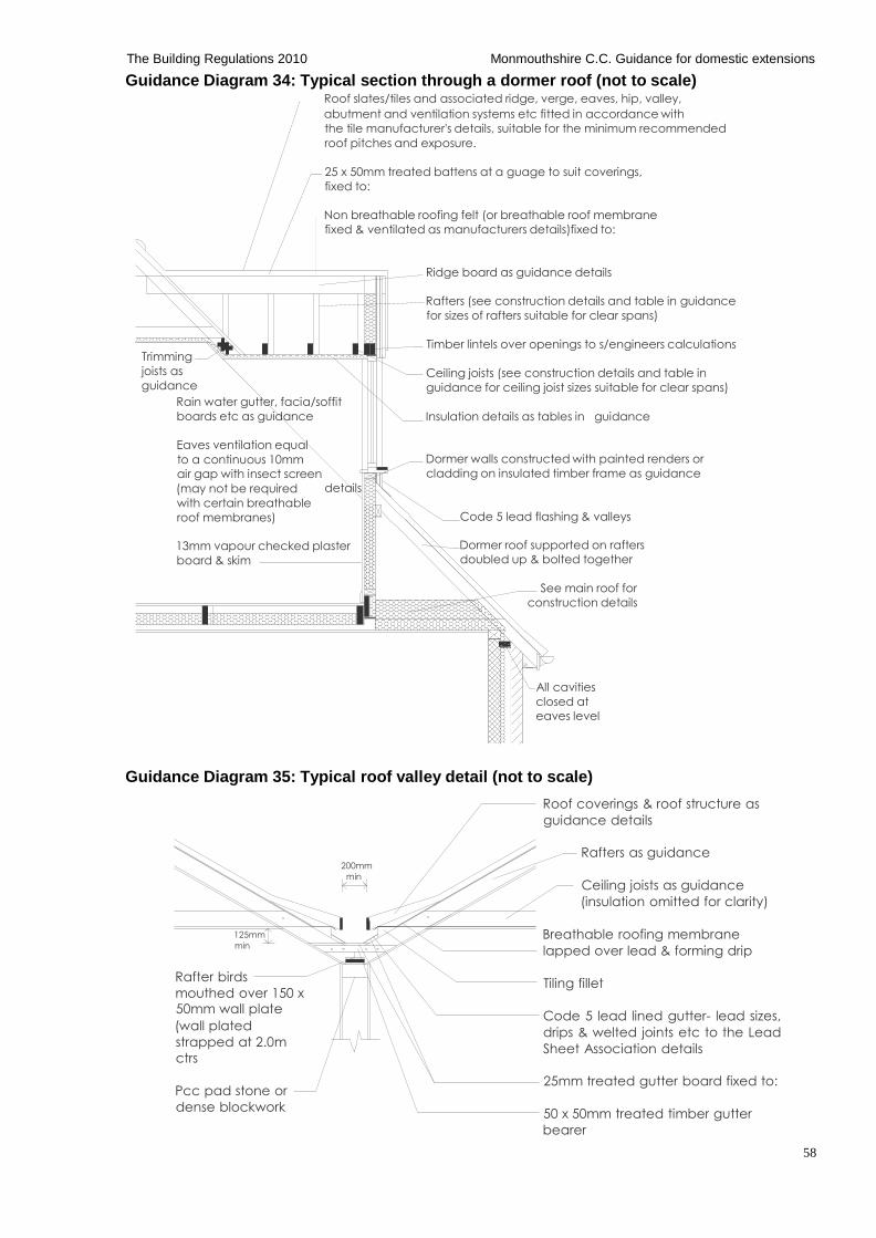
58
The Building Regulations 2010 Monmouthshire C.C. Guidance for domestic extensions
Guidance Diagram 34: Typical section through a dormer roof (not to scale) Roof slates/tiles and associated ridge, verge, eaves, hip, valley,
abutment and ventilation systems etc fitted in accordance with
the tile manufacturer's details, suitable for the minimum recommended
roof pitches and exposure.
25 x 50mm treated battens at a guage to suit coverings,
fixed to:
Non breathable roofing felt (or breathable roof membrane
fixed & ventilated as manufacturers details)fixed to:
Ridge board as guidance details
Rafters (see construction details and table in guidance
for sizes of rafters suitable for clear spans)
Trimming
joists as
guidance
Rain water gutter, facia/soffit
boards etc as guidance
Timber lintels over openings to s/engineers calculations
Ceiling joists (see construction details and table in
guidance for ceiling joist sizes suitable for clear spans)
Insulation details as tables in guidance
Eaves ventilation equal
to a continuous 10mm
air gap with insect screen
(may not be required
with certain breathable
roof membranes)
details
Dormer walls constructed with painted renders or
cladding on insulated timber frame as guidance
Code 5 lead flashing & valleys
13mm vapour checked plaster
board & skim
Dormer roof supported on rafters
doubled up & bolted together
See main roof for
construction details
All cavities
closed at
eaves level
Guidance Diagram 35: Typical roof valley detail (not to scale)
Roof coverings & roof structure as
guidance details
125mm
min
Rafter birds
mouthed over 150 x 50mm wall plate
(wall plated
strapped at 2.0m
ctrs
Pcc pad stone or
dense blockwork
200mm
min
Rafters as guidance
Ceiling joists as guidance
(insulation omitted for clarity)
Breathable roofing membrane
lapped over lead & forming drip
Tiling fillet
Code 5 lead lined gutter- lead sizes,
drips & welted joints etc to the Lead
Sheet Association details
25mm treated gutter board fixed to:
50 x 50mm treated timber gutter
bearer
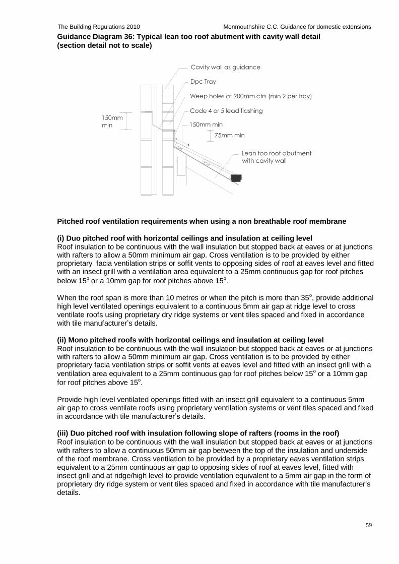
59
The Building Regulations 2010 Monmouthshire C.C. Guidance for domestic extensions
Guidance Diagram 36: Typical lean too roof abutment with cavity wall detail
(section detail not to scale)
Cavity wall as guidance
Dpc Tray
Weep holes at 900mm ctrs (min 2 per tray)
150mm
min
Code 4 or 5 lead flashing 150mm min
75mm min
Lean too roof abutment
with cavity wall
Pitched roof ventilation requirements when using a non breathable roof membrane (i) Duo pitched roof with horizontal ceilings and insulation at ceiling level Roof insulation to be continuous with the wall insulation but stopped back at eaves or at junctions with rafters to allow a 50mm minimum air gap. Cross ventilation is to be provided by either proprietary facia ventilation strips or soffit vents to opposing sides of roof at eaves level and fitted with an insect grill with a ventilation area equivalent to a 25mm continuous gap for roof pitches
below 15o or a 10mm gap for roof pitches above 15o. When the roof span is more than 10 metres or when the pitch is more than 35o, provide additional high level ventilated openings equivalent to a continuous 5mm air gap at ridge level to cross ventilate roofs using proprietary dry ridge systems or vent tiles spaced and fixed in accordance with tile manufacturer’s details.
(ii) Mono pitched roofs with horizontal ceilings and insulation at ceiling level Roof insulation to be continuous with the wall insulation but stopped back at eaves or at junctions with rafters to allow a 50mm minimum air gap. Cross ventilation is to be provided by either proprietary facia ventilation strips or soffit vents at eaves level and fitted with an insect grill with a
ventilation area equivalent to a 25mm continuous gap for roof pitches below 15o or a 10mm gap
for roof pitches above 15o. Provide high level ventilated openings fitted with an insect grill equivalent to a continuous 5mm air gap to cross ventilate roofs using proprietary ventilation systems or vent tiles spaced and fixed in accordance with tile manufacturer’s details.
(iii) Duo pitched roof with insulation following slope of rafters (rooms in the roof)
Roof insulation to be continuous with the wall insulation but stopped back at eaves or at junctions with rafters to allow a continuous 50mm air gap between the top of the insulation and underside of the roof membrane. Cross ventilation to be provided by a proprietary eaves ventilation strips equivalent to a 25mm continuous air gap to opposing sides of roof at eaves level, fitted with insect grill and at ridge/high level to provide ventilation equivalent to a 5mm air gap in the form of proprietary dry ridge system or vent tiles spaced and fixed in accordance with tile manufacturer’s details.
60
The Building Regulations 2010 Monmouthshire C.C. Guidance for domestic extensions
Proprietary vapour permeable roof membrane
Ventilation to the roof space may be omitted, only if a proprietary British Board of Agreement (BBA or other third party accredited) vapour permeable breathable roof membrane is used. Vapour permeable breathable roof membranes must always be installed in strict accordance with manufacturer's details (note. some breathable membranes may also require additional roof ventilation in accordance with manufacturer's details)
Valleys and lead work Lead work, flashing, soakers, valleys and gutters, etc, to be formed from Code 5 lead sheet and fully supported on treated valley boards, etc, and to have a minimum 150mm lap joints, dressed 200mm under tiles, etc, and not to be fixed in lengths exceeding 1.5m and to be fixed in accordance with the roof cladding manufacturer's and the Lead Sheet Association recommendations.
Lofts hatches, doors and Light wells to roof spaces All hatches, doors and light wells in the roof space to be insulated to the same standard as the roof, draft stripped and positively fixed.
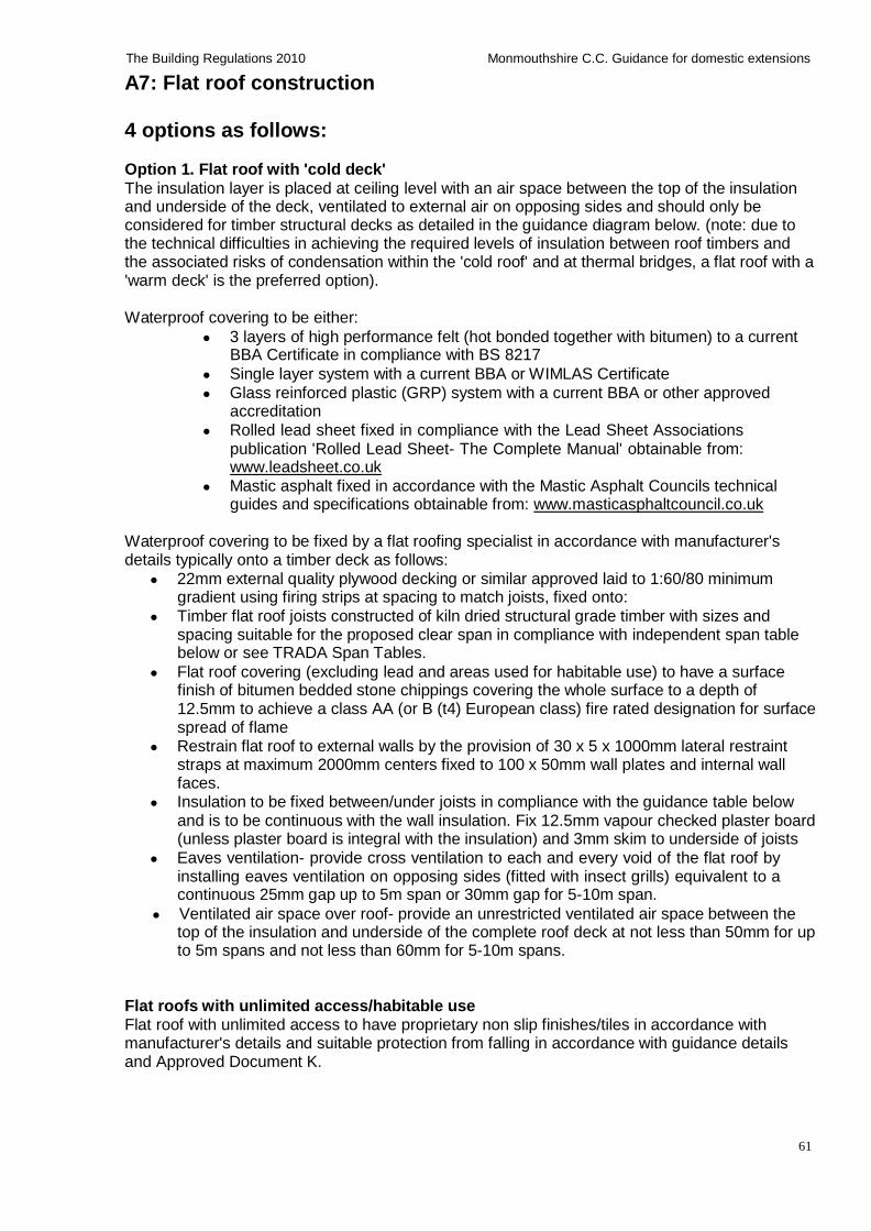
61
The Building Regulations 2010 Monmouthshire C.C. Guidance for domestic extensions
A7: Flat roof construction
4 options as follows: Option 1. Flat roof with 'cold deck'
The insulation layer is placed at ceiling level with an air space between the top of the insulation and underside of the deck, ventilated to external air on opposing sides and should only be considered for timber structural decks as detailed in the guidance diagram below. (note: due to the technical difficulties in achieving the required levels of insulation between roof timbers and the associated risks of condensation within the 'cold roof' and at thermal bridges, a flat roof with a 'warm deck' is the preferred option).
Waterproof covering to be either:
3 layers of high performance felt (hot bonded together with bitumen) to a current BBA Certificate in compliance with BS 8217
Single layer system with a current BBA or WIMLAS Certificate
Glass reinforced plastic (GRP) system with a current BBA or other approved accreditation
Rolled lead sheet fixed in compliance with the Lead Sheet Associations publication 'Rolled Lead Sheet- The Complete Manual' obtainable from: www.leadsheet.co.uk
Mastic asphalt fixed in accordance with the Mastic Asphalt Councils technical guides and specifications obtainable from: www.masticasphaltcouncil.co.uk
Waterproof covering to be fixed by a flat roofing specialist in accordance with manufacturer's details typically onto a timber deck as follows:
22mm external quality plywood decking or similar approved laid to 1:60/80 minimum gradient using firing strips at spacing to match joists, fixed onto:
Timber flat roof joists constructed of kiln dried structural grade timber with sizes and spacing suitable for the proposed clear span in compliance with independent span table below or see TRADA Span Tables.
Flat roof covering (excluding lead and areas used for habitable use) to have a surface finish of bitumen bedded stone chippings covering the whole surface to a depth of 12.5mm to achieve a class AA (or B (t4) European class) fire rated designation for surface spread of flame
Restrain flat roof to external walls by the provision of 30 x 5 x 1000mm lateral restraint straps at maximum 2000mm centers fixed to 100 x 50mm wall plates and internal wall faces.
Insulation to be fixed between/under joists in compliance with the guidance table below and is to be continuous with the wall insulation. Fix 12.5mm vapour checked plaster board (unless plaster board is integral with the insulation) and 3mm skim to underside of joists
Eaves ventilation- provide cross ventilation to each and every void of the flat roof by installing eaves ventilation on opposing sides (fitted with insect grills) equivalent to a continuous 25mm gap up to 5m span or 30mm gap for 5-10m span.
Ventilated air space over roof- provide an unrestricted ventilated air space between the top of the insulation and underside of the complete roof deck at not less than 50mm for up to 5m spans and not less than 60mm for 5-10m spans.
Flat roofs with unlimited access/habitable use Flat roof with unlimited access to have proprietary non slip finishes/tiles in accordance with manufacturer's details and suitable protection from falling in accordance with guidance details and Approved Document K.
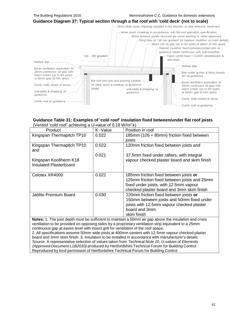
62
The Building Regulations 2010 Monmouthshire C.C. Guidance for domestic extensions
Guidance Diagram 37: Typical section through a flat roof with 'cold deck' (not to scale) 13mm diam stone chippings bedded in hot bitumen or solar reflective treatment
Welted drip
1:60 - 1:80 gradient
Water proof coverings in accordance with flat roof specialists specification
22mm external quality structural ply wood decking or other approved
Firing strips at 1:60 min gradient (or tapered insulation as manf details)
50mm min air gap (up to 5m span) or 60mm (5-10m span)
Thermal insulation fixed between/under joists as
guidance tables continuous with wall insulation
Vapor contol layer + 12.5mm plasterboard &
skim finish
Eaves ventilation equivalent to
25mm continuous air gap with
insect screen (up to 5m span)
or 30mm gap (5-10m span)
Cavity walls closed at eaves
Flat roof joist sizes and spacing suitable
for clear spans & loadings as guidance
Welted drip
Rain water gutters & facia boards
etc as guidance
Eaves ventilation equivalent to
25mm continuous air gap with
wall plate & strapping as
guidance
Cavity wall as guidance
tables wall plate & strapping as
guidance
insect screen (up to 5m span)
or 30mm gap (5-10m span)
Cavity walls closed at eaves
Cavity wall as guidance
Guidance Table 31: Examples of 'cold roof' insulation fixed between/under flat roof joists (Vented ‘cold roof’ achieving a U-value of 0.18 W/m².k)
Product K -Value Position in roof
Kingspan Thermapitch TP10 0.022 185mm (105 + 80mm) friction fixed between joists
Kingspan Thermapitch TP10 and
Kingspan Kooltherm K18 Insulated Plasterboard
0.022 0.021
120mm friction fixed between joists and 37.5mm fixed under rafters, with integral vapour checked plaster board and skim finish
Celotex XR4000 0.022 185mm friction fixed between joists or 125mm friction fixed between joists and 25mm fixed under joists, with 12.5mm vapour checked plaster board and 3mm skim finish
Jablite Premium Board 0.030 220mm friction fixed between joists or 150mm between joists and 50mm fixed under joists with 12.5mm vapour checked plaster board and 3mm skim finish
Notes: 1. The joist depth must be sufficient to maintain a 50mm air gap above the insulation and cross ventilation to be provided on opposing sides by a proprietary ventilation strip equivalent to a 25mm continuous gap at eaves level with insect grill for ventilation of the roof space. 2. All specifications assume 50mm wide joists at 400mm centers with 12.5mm vapour checked plaster board and 3mm skim finish. 3. Insulation to be installed in accordance with manufacturer's details Source: A representative selection of values taken from Technical Note 10, U-values of Elements (Approved Document L1B2010) produced by Hertfordshire Technical Forum for Building Control.
Reproduced by kind permission of Hertfordshire Technical Forum for Building Control
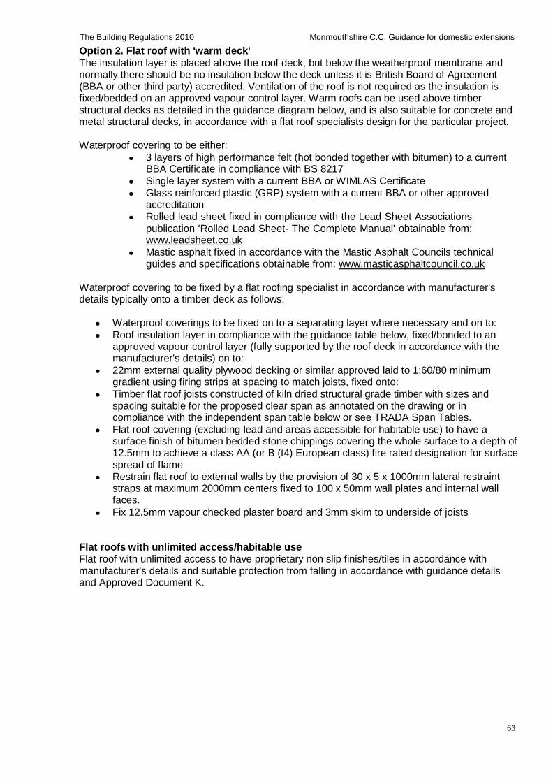
63
The Building Regulations 2010 Monmouthshire C.C. Guidance for domestic extensions
Option 2. Flat roof with 'warm deck'
The insulation layer is placed above the roof deck, but below the weatherproof membrane and normally there should be no insulation below the deck unless it is British Board of Agreement (BBA or other third party) accredited. Ventilation of the roof is not required as the insulation is fixed/bedded on an approved vapour control layer. Warm roofs can be used above timber structural decks as detailed in the guidance diagram below, and is also suitable for concrete and metal structural decks, in accordance with a flat roof specialists design for the particular project.
Waterproof covering to be either:
3 layers of high performance felt (hot bonded together with bitumen) to a current BBA Certificate in compliance with BS 8217
Single layer system with a current BBA or WIMLAS Certificate
Glass reinforced plastic (GRP) system with a current BBA or other approved accreditation
Rolled lead sheet fixed in compliance with the Lead Sheet Associations publication 'Rolled Lead Sheet- The Complete Manual' obtainable from: www.leadsheet.co.uk
Mastic asphalt fixed in accordance with the Mastic Asphalt Councils technical guides and specifications obtainable from: www.masticasphaltcouncil.co.uk
Waterproof covering to be fixed by a flat roofing specialist in accordance with manufacturer's details typically onto a timber deck as follows:
Waterproof coverings to be fixed on to a separating layer where necessary and on to:
Roof insulation layer in compliance with the guidance table below, fixed/bonded to an approved vapour control layer (fully supported by the roof deck in accordance with the manufacturer's details) on to:
22mm external quality plywood decking or similar approved laid to 1:60/80 minimum gradient using firing strips at spacing to match joists, fixed onto:
Timber flat roof joists constructed of kiln dried structural grade timber with sizes and spacing suitable for the proposed clear span as annotated on the drawing or in compliance with the independent span table below or see TRADA Span Tables.
Flat roof covering (excluding lead and areas accessible for habitable use) to have a surface finish of bitumen bedded stone chippings covering the whole surface to a depth of 12.5mm to achieve a class AA (or B (t4) European class) fire rated designation for surface spread of flame
Restrain flat roof to external walls by the provision of 30 x 5 x 1000mm lateral restraint straps at maximum 2000mm centers fixed to 100 x 50mm wall plates and internal wall faces.
Fix 12.5mm vapour checked plaster board and 3mm skim to underside of joists
Flat roofs with unlimited access/habitable use Flat roof with unlimited access to have proprietary non slip finishes/tiles in accordance with manufacturer's details and suitable protection from falling in accordance with guidance details and Approved Document K.
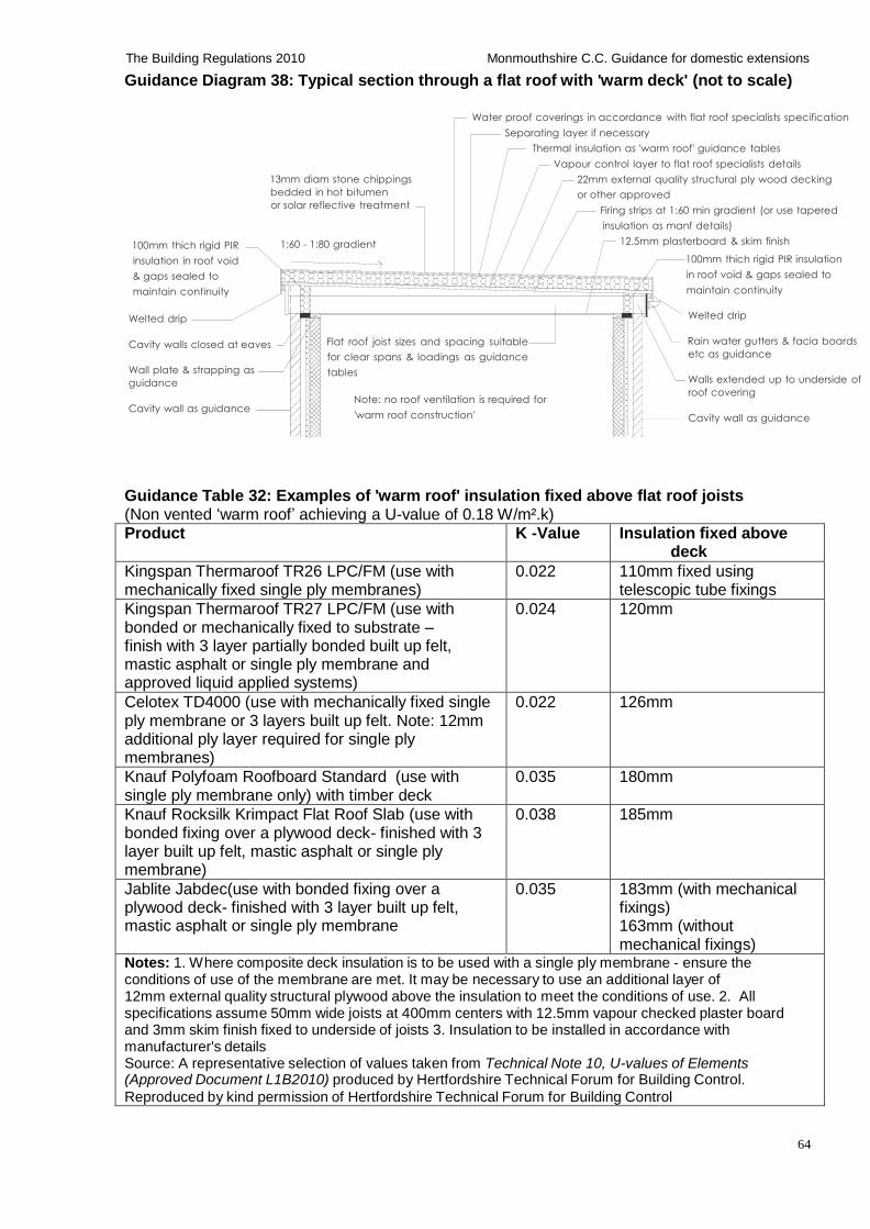
64
The Building Regulations 2010 Monmouthshire C.C. Guidance for domestic extensions
Guidance Diagram 38: Typical section through a flat roof with 'warm deck' (not to scale)
100mm thich rigid PIR
insulation in roof void
& gaps sealed to
maintain continuity
Welted drip
13mm diam stone chippings
bedded in hot bitumen
or solar reflective treatment
1:60 - 1:80 gradient
Water proof coverings in accordance with flat roof specialists specification
Separating layer if necessary
Thermal insulation as 'warm roof' guidance tables
Vapour control layer to flat roof specialists details
22mm external quality structural ply wood decking
or other approved
Firing strips at 1:60 min gradient (or use tapered
insulation as manf details)
12.5mm plasterboard & skim finish
100mm thich rigid PIR insulation
in roof void & gaps sealed to
maintain continuity
Welted drip
Cavity walls closed at eaves
Wall plate & strapping as
guidance
Cavity wall as guidance
Flat roof joist sizes and spacing suitable
for clear spans & loadings as guidance
tables
Note: no roof ventilation is required for
'warm roof construction'
Rain water gutters & facia boards
etc as guidance
Walls extended up to underside of
roof covering
Cavity wall as guidance
Guidance Table 32: Examples of 'warm roof' insulation fixed above flat roof joists (Non vented ‘warm roof’ achieving a U-value of 0.18 W/m².k) Product K -Value Insulation fixed above
deck
Kingspan Thermaroof TR26 LPC/FM (use with mechanically fixed single ply membranes)
0.022 110mm fixed using telescopic tube fixings
Kingspan Thermaroof TR27 LPC/FM (use with bonded or mechanically fixed to substrate – finish with 3 layer partially bonded built up felt, mastic asphalt or single ply membrane and approved liquid applied systems)
0.024 120mm
Celotex TD4000 (use with mechanically fixed single ply membrane or 3 layers built up felt. Note: 12mm additional ply layer required for single ply membranes)
0.022 126mm
Knauf Polyfoam Roofboard Standard (use with single ply membrane only) with timber deck
0.035 180mm
Knauf Rocksilk Krimpact Flat Roof Slab (use with bonded fixing over a plywood deck- finished with 3 layer built up felt, mastic asphalt or single ply membrane)
0.038 185mm
Jablite Jabdec(use with bonded fixing over a plywood deck- finished with 3 layer built up felt, mastic asphalt or single ply membrane
0.035 183mm (with mechanical fixings) 163mm (without mechanical fixings)
Notes: 1. Where composite deck insulation is to be used with a single ply membrane - ensure the conditions of use of the membrane are met. It may be necessary to use an additional layer of 12mm external quality structural plywood above the insulation to meet the conditions of use. 2. All specifications assume 50mm wide joists at 400mm centers with 12.5mm vapour checked plaster board and 3mm skim finish fixed to underside of joists 3. Insulation to be installed in accordance with manufacturer's details Source: A representative selection of values taken from Technical Note 10, U-values of Elements (Approved Document L1B2010) produced by Hertfordshire Technical Forum for Building Control.
Reproduced by kind permission of Hertfordshire Technical Forum for Building Control
65
The Building Regulations 2010 Monmouthshire C.C. Guidance for domestic extensions
Option 3. Flat roof with inverted 'warm deck' (insulation on top of waterproof coverings) Typically constructed as a ballast layer, over a filter layer, over insulation layer, over water proof coverings/ vapour control layer and structural deck, designed and constructed by a flat roofing specialist. Not covered by this guidance.
Option 4. Flat roof with green roof on 'warm deck' (Either intensive or extensive)
Intensive green roof Typically constructed with vegetation in 1.0m deep soil layer,over filter layer, over drainage/ reservoir layer, over protective layer, over root barrier, over water proof coverings/ vapour control layer and structural deck, designed and constructed by a flat roofing specialist. Not covered by this guidance.
Extensive green roof Typically constructed with Sedum blanket, over filter layer, over root barrier, over water proof coverings/ vapour control layer and structural deck, designed and constructed by a flat roofing specialist. Not covered by this guidance.
The design, workmanship and selection of materials for flat roofs The
design, workmanship and selection of materials should comply with Model Specification Sheet P.L.1 Built-Up Roofing: Plywood Deck, published by The British Flat Roofing Council. Metallic roof trims to be of non-corrodible material and resistant to sunlight and not fixed through the water proof covering. All timber to be treated using CCA vacuum/pressure or O/S double vacuum to BS 5268:5, including all cut ends of timber etc 300mm of any joint.
All flat roofing works to be carried out by a specialist flat roofing contractor and all materials etc to be fitted in compliance with manufacturer’s details. Work should not be carried out during wet weather or when the deck has not fully dried out. A vapour control barrier is required on the underside of the roof below the insulation level, (typically 500g polythene or foil backed plaster board). Fix 12.5mm plasterboard (joints staggered) and 5mm skim coat of finishing plaster to the underside of all ceilings using galvanized plasterboard nails.
Flat roof to be carried out as detailed on the drawings. Moisture content of timber should not exceed 20% and to be kiln dried and grade C24. Workmanship to comply to BS 8000:4. All fixings to be proprietary stainless steel or galvanized steel.
Cavity closers Proprietary British Board of Agreement (BBA or other third party accredited) acoustic/thermally insulated/fire resistant cavity closers, or similar are to be provided to all cavity openings/closings, tops of walls and junctions with other properties in accordance with manufacturer's details.
Tops of cavity walls can be closed to prevent the passage of fire using a proprietary British Board of Agreement (BBA or other third party accredited) 30 minutes fire resistant rigid board, fixed in accordance with manufacturer's details.
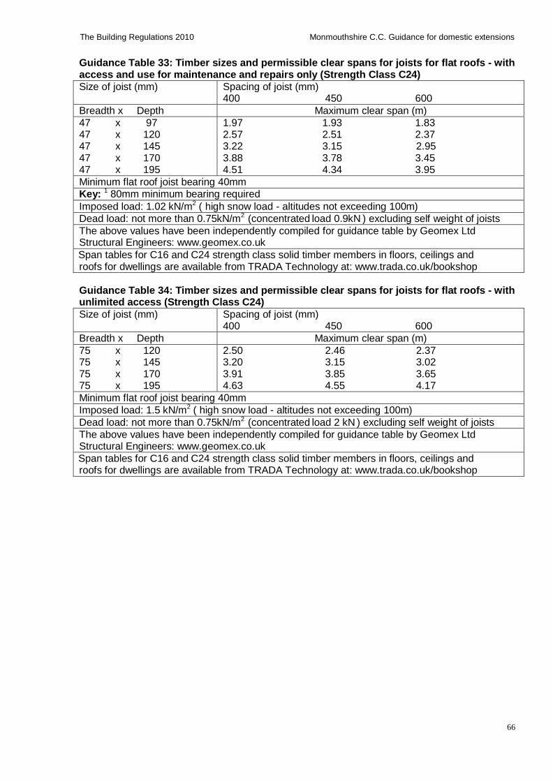
66
The Building Regulations 2010 Monmouthshire C.C. Guidance for domestic extensions
Guidance Table 33: Timber sizes and permissible clear spans for joists for flat roofs - with access and use for maintenance and repairs only (Strength Class C24)
Size of joist (mm) Spacing of joist (mm) 400 450 600
Breadth x Depth Maximum clear span (m)
47 x 97 47 x 120 47 x 145 47 x 170 47 x 195
1.97 1.93 1.83 2.57 2.51 2.37 3.22 3.15 2.95 3.88 3.78 3.45 4.51 4.34 3.95
Minimum flat roof joist bearing 40mm
Key: 1 80mm minimum bearing required
Imposed load: 1.02 kN/m2 ( high snow load - altitudes not exceeding 100m)
Dead load: not more than 0.75kN/m2 (concentrated load 0.9kN ) excluding self weight of joists
The above values have been independently compiled for guidance table by Geomex Ltd Structural Engineers: www.geomex.co.uk
Span tables for C16 and C24 strength class solid timber members in floors, ceilings and roofs for dwellings are available from TRADA Technology at: www.trada.co.uk/bookshop
Guidance Table 34: Timber sizes and permissible clear spans for joists for flat roofs - with unlimited access (Strength Class C24)
Size of joist (mm) Spacing of joist (mm) 400 450 600
Breadth x Depth Maximum clear span (m)
75 x 120 75 x 145 75 x 170 75 x 195
2.50 2.46 2.37 3.20 3.15 3.02 3.91 3.85 3.65 4.63 4.55 4.17
Minimum flat roof joist bearing 40mm
Imposed load: 1.5 kN/m2 ( high snow load - altitudes not exceeding 100m)
Dead load: not more than 0.75kN/m2 (concentrated load 2 kN ) excluding self weight of joists
The above values have been independently compiled for guidance table by Geomex Ltd Structural Engineers: www.geomex.co.uk
Span tables for C16 and C24 strength class solid timber members in floors, ceilings and roofs for dwellings are available from TRADA Technology at: www.trada.co.uk/bookshop
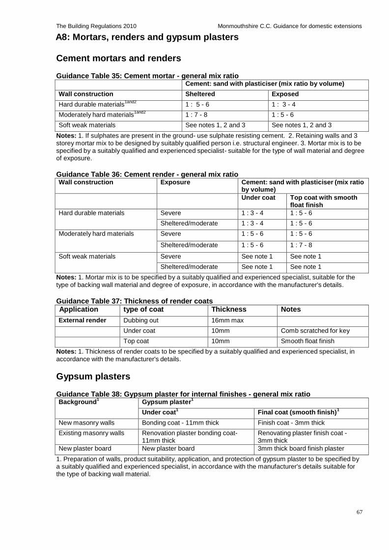
67
The Building Regulations 2010 Monmouthshire C.C. Guidance for domestic extensions
A8: Mortars, renders and gypsum plasters
Cement mortars and renders
Guidance Table 35: Cement mortar - general mix ratio
Cement: sand with plasticiser (mix ratio by volume)
Wall construction Sheltered Exposed
Hard durable materials1and2
1 : 5 - 6 1 : 3 - 4
Moderately hard materials1and2
1 : 7 - 8 1 : 5 - 6
Soft weak materials See notes 1, 2 and 3 See notes 1, 2 and 3
Notes: 1. If sulphates are present in the ground- use sulphate resisting cement. 2. Retaining walls and 3 storey mortar mix to be designed by suitably qualified person i.e. structural engineer. 3. Mortar mix is to be specified by a suitably qualified and experienced specialist- suitable for the type of wall material and degree of exposure.
Guidance Table 36: Cement render - general mix ratio Wall construction Exposure Cement: sand with plasticiser (mix ratio
by volume)
Under coat Top coat with smooth float finish
Hard durable materials Severe 1 : 3 - 4 1 : 5 - 6
Sheltered/moderate 1 : 3 - 4 1 : 5 - 6
Moderately hard materials Severe 1 : 5 - 6 1 : 5 - 6
Sheltered/moderate 1 : 5 - 6 1 : 7 - 8
Soft weak materials Severe See note 1 See note 1
Sheltered/moderate See note 1 See note 1
Notes: 1. Mortar mix is to be specified by a suitably qualified and experienced specialist, suitable for the type of backing wall material and degree of exposure, in accordance with the manufacturer's details.
Guidance Table 37: Thickness of render coats
Application type of coat Thickness Notes
External render Dubbing out 16mm max
Under coat 10mm Comb scratched for key
Top coat 10mm Smooth float finish
Notes: 1. Thickness of render coats to be specified by a suitably qualified and experienced specialist, in accordance with the manufacturer's details.
Gypsum plasters
Guidance Table 38: Gypsum plaster for internal finishes - general mix ratio Background
1 Gypsum plaster
1
Under coat1
Final coat (smooth finish)1
New masonry walls Bonding coat - 11mm thick Finish coat - 3mm thick
Existing masonry walls Renovation plaster bonding coat- 11mm thick
Renovating plaster finish coat - 3mm thick
New plaster board New plaster board 3mm thick board finish plaster
1. Preparation of walls, product suitability, application, and protection of gypsum plaster to be specified by a suitably qualified and experienced specialist, in accordance with the manufacturer's details suitable for the type of backing wall material.
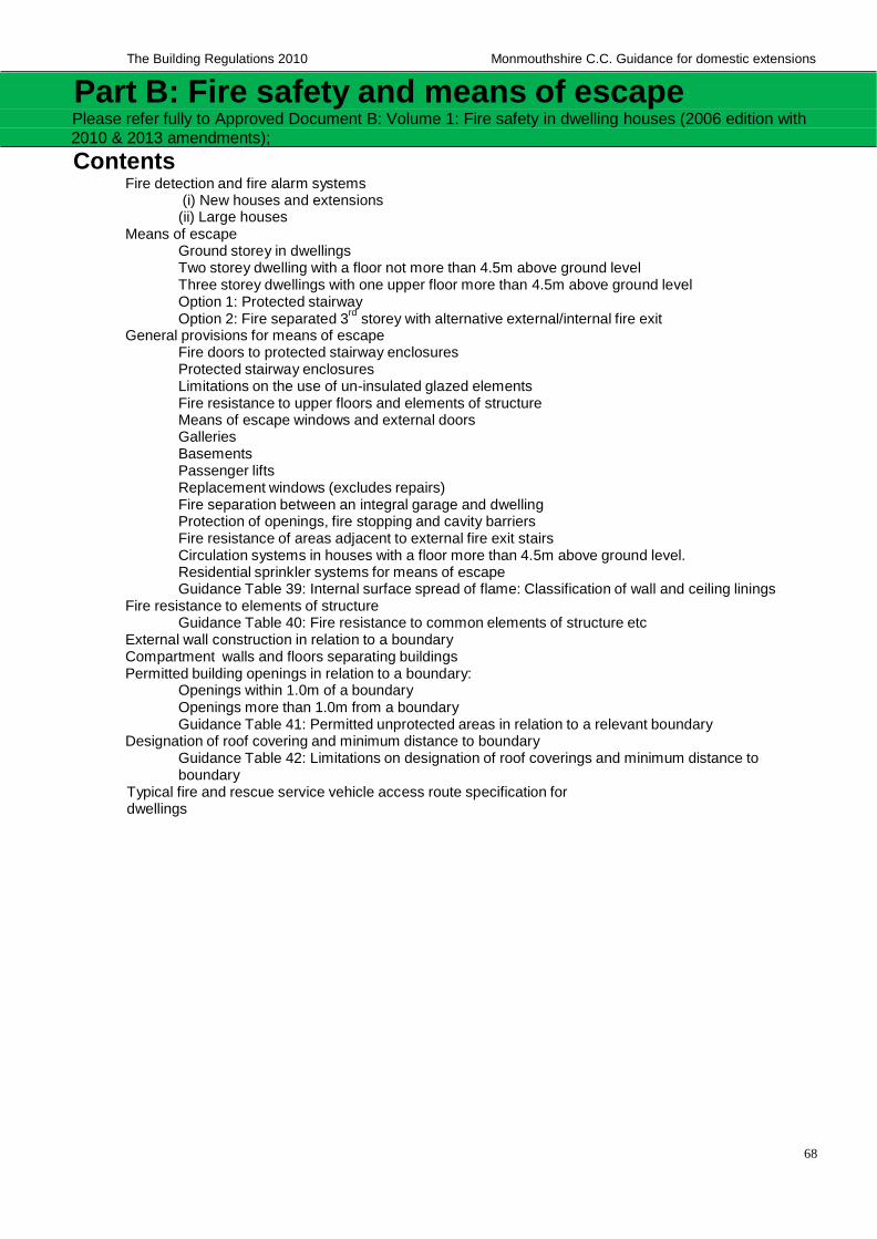
68
The Building Regulations 2010 Monmouthshire C.C. Guidance for domestic extensions
Part B: Fire safety and means of escape Please refer fully to Approved Document B: Volume 1: Fire safety in dwelling houses (2006 edition with
2010 & 2013 amendments);
Contents Fire detection and fire alarm systems
(i) New houses and extensions (ii) Large houses
Means of escape Ground storey in dwellings Two storey dwelling with a floor not more than 4.5m above ground level Three storey dwellings with one upper floor more than 4.5m above ground level Option 1: Protected stairway
Option 2: Fire separated 3rd
storey with alternative external/internal fire exit
General provisions for means of escape Fire doors to protected stairway enclosures Protected stairway enclosures Limitations on the use of un-insulated glazed elements Fire resistance to upper floors and elements of structure Means of escape windows and external doors Galleries Basements Passenger lifts Replacement windows (excludes repairs) Fire separation between an integral garage and dwelling Protection of openings, fire stopping and cavity barriers Fire resistance of areas adjacent to external fire exit stairs Circulation systems in houses with a floor more than 4.5m above ground level. Residential sprinkler systems for means of escape Guidance Table 39: Internal surface spread of flame: Classification of wall and ceiling linings
Fire resistance to elements of structure Guidance Table 40: Fire resistance to common elements of structure etc
External wall construction in relation to a boundary Compartment walls and floors separating buildings Permitted building openings in relation to a boundary:
Openings within 1.0m of a boundary Openings more than 1.0m from a boundary Guidance Table 41: Permitted unprotected areas in relation to a relevant boundary
Designation of roof covering and minimum distance to boundary Guidance Table 42: Limitations on designation of roof coverings and minimum distance to boundary
Typical fire and rescue service vehicle access route specification for dwellings
69
The Building Regulations 2010 Monmouthshire C.C. Guidance for domestic extensions
Part B: Fire safety and means of escape
Fire detection and fire alarm systems Self contained mains operated smoke alarms with battery backup to BS EN 14604, and fire alarm and fire alarm systems to be installed in accordance with BS 5839 to the following standards:
(i) New houses and extensions: Grade D Category to a LD3 standard
Self contained mains operated smoke alarms with battery backup to BS 5446, to be installed in accordance with the relevant recommendations of BS 5839 Part 6: 2004 as follows:
in all circulation areas at each storey level that form part of the escape route from the dwelling
within 7.5m of all doors to habitable rooms.
sited at least 300mm from walls and light fittings
interconnected together
Heat alarms to be installed in kitchens if the kitchen is open to the stairway or circulation area (in two storey dwellings).
(ii) Large houses - which has more than 1 storey and any of those storeys exceed 200m2 as follows:
a. Large 2 storey house (excluding basement) - Grade B Category to a LD3 standard
Fire detection and alarm system comprising fire detectors (other than smoke/heat alarms), fire alarm sounders and control and indicating equipment to either BS EN 54-2 (and power supply to BS EN 54-4), or to Annex C of BS 5839: Pt.6
Detection system to be installed in all circulation areas at each storey level that form part of the escape route from the dwelling
b. Large 3 storey house (excluding basements) - Grade A Category to a LD2 standard
(smoke/heat alarms sited in accordance with BS 5839-1 for a Category L2 system)
Fire detection and alarm system incorporating control and indicating equipment to BS EN 54-2, and power supply to BS EN 54-4, installed to BS 5839: Pt.1 with some minor exceptions
Detection system to be installed in all circulation spaces that form part of the escape routes from the dwelling, and in all rooms or areas that present a high risk of fire.
Means of escape
Ground storey in dwellings
Except for kitchens, all habitable rooms in the ground storey should either: (i) open directly onto a hall leading to the entrance or other suitable exit; or (ii) be provided with a means of escape window (or door) in compliance with the guidance details below.
Two storey dwelling with a floor not more than 4.5m above ground level Habitable rooms in the first floor storey served by only one stairs should either: (i) be provided with a means of escape windows (or doors) in compliance with the guidance details below; or (ii) provided with direct access to a protected stairs as described in three storey buildings guidance below.
70
The Building Regulations 2010 Monmouthshire C.C. Guidance for domestic extensions
Three storey dwellings with one upper floor more than 4.5m above ground level
The dwelling house may either have a protected stairs as described in option 1 below or the top floor can be separated and given its own alternative escape route as described in option 2 below. Alternatively, where the fire safety requirements of the building regulations cannot be met, a sprinkler system may be allowed against the requirements of Approved Document B as described in the guidance below. Important note: The options below need not be followed if the dwelling house has more than one internal stairway, which affords an effective alternative means of escape in two directions and are physically separated from each other (to be approved by building control).
Option 1: Protected stairway
The stairs, landings and hallway from the top storey down to the ground floor must be protected and enclosed in 30-minute fire resisting construction and the doors fitted with FD 20 fire doors (as detailed below), the protected stairs must discharge directly to an external door at ground level or the protected stairs can give access to at least two escape routes and final exits separated by 30 minutes fire resisting construction at ground level. Note: Toilets and bathrooms onto the protected stairs do not require fire doors providing the partitions between the toilet/bathroom and the rooms onto the stairs has 30 minutes fire resistance from both sides and there is no heat producing appliances fitted in the toilet/bathroom. All cupboards onto the stairs will require FD 20 fire doors.
Option 2: Fire separated 3rd storey with alternative external/internal fire exit
The top 3rd storey should be separated from the lower storeys by 30 minute fire resisting construction and provided with an alternative escape route leading to its own final exit. Fire resistance of areas adjacent to external stairs are detailed in the guidance below.
General provisions for means of escape Fire doors to protected stairway enclosures Fire doors to protected stairway enclosures to be FD 20 fire resisting doors having 20 minutes fire resistance to BS 476-22:1987, fitted with intumescent strips rebated around sides and top of door or frame, excludes toilets/bathrooms/en-suite-providing the partitions protecting the stairs has 30 minutes fire resistance from both sides. (Note: a self closing FD30 fire door is required between the dwelling/garage in accordance with the guidance details below)
Existing/new solid hardwood/timber doors may achieve 20 minutes fire or doors may be suitable for upgrading to achieve 20 minutes fire resistance (as agreed with building control) with a proprietary intumescent paint/paper system in accordance with manufacturer's details. More details are available from: www.fireproof.co.uk, who can supply (and apply where required) an intumescent paint/paper system which must be applied in accordance with the manufacturer's details. A copy of the manufacturer's certificate of purchase/ application must be provided for building control on completion. Upgraded doors/frames to be fitted with intumescent strips as detailed in the guidance above.
Protected stairway enclosures
To have 30 minutes fire resisting construction from both sides, constructed in accordance with partition wall details in Part A of this guidance
Limitations on the use of un-insulated glazed elements Limitations on the use of un-insulated glazed elements on escape routes to be in compliance with Table A4 of Approved Document B: Volume 1- Dwelling Houses. (un-insulated refers to the fire insulation value of the glazing (normally 30 minutes) and not the thermal insulation value)
71
The Building Regulations 2010 Monmouthshire C.C. Guidance for domestic extensions
Fire resistance to upper floors and elements of structure
Upper floors to have 30 minutes fire resisting construction from the underside, constructed in accordance with upper floor details in Part A of this guidance, other elements of structure to have fire resistance in compliance with the guidance table below.
Means of escape windows and external doors
Means of escape windows to be fitted with proprietary hinges to open the window to the minimum required clear width of 450mm. Escape windows must have minimum clear opening casement dimensions of 0.33m² (typically 450mm wide x 750mm high), with the opening located between 800-1100mm above floor level to all bedrooms and habitable rooms at first floor level and inner habitable rooms on the ground floor level. (roof window openings may be acceptable 600mm above floor level subject to approval by building control)
The means of escape window or door should lead to a place of safety away from the fire. A courtyard or back garden from which there is no exit other than through other buildings would have to be at least as deep as the dwelling house is high to be acceptable as detailed in Par 2.8 (b) and Diagram 4 of ADB V1.
Windows above the ground floor storey and within 800mm of floor level are to be provided with containment/ guarding/ proprietary catches which should be removable (child proof) in the event of a fire. Where an escape window cannot be achieved, direct access to a protected stairs (or protected route to inner rooms) is acceptable in compliance with guidance details above for 3 storey buildings and ADB V1par 2.6 (a) or (b).
Windows should be designed to remain in the open position whilst making an escape
Locks (with or without removable keys) and stays may be fitted to escape windows, subject to the stay being fitted with a release catch which is child resistant.
Galleries A gallery floor providing a raised area or platform around the sides or at the back of a room (to provide extra space) should be provided with:
an alternative exit or,
where the gallery floor is not more than 4.5m above ground level, a means of escape window in accordance with guidance details above.
Where a gallery is not provided with an alternative exit or means of escape window, it should comply with the following requirements (see Diagram 5 of ADB V1 for full details):
the gallery should overlook at least 50% of the room below;
the distance between the foot of the access stairs to the gallery and the door to the room containing the gallery should not exceed 3m;
the distance from the head of the access stairs to any point on the gallery should not exceed 7.5m and;
any cooking facilities within a room containing a gallery should either: (i) be enclosed in fire resisting construction; or (ii) be remote from the stair to the gallery and positioned such that they do not prejudice the escape from the gallery
Basements If the basement storey is served by a single stairway and contains a habitable room, the basement should be either fitted with a means of escape window or door in compliance with this guidance or a protected stairs leading from the basement to the final exit in compliance with guidance details for 3 storey buildings. Fire resistant glazing in protected routes is to be in compliance with Table 4 of ADB V1
72
The Building Regulations 2010 Monmouthshire C.C. Guidance for domestic extensions
Passenger lifts
Lifts installed in dwellings with a floor more than 4.5m above ground level should either be located within the enclosures to the protected stairway or contained in a 30 minute fire resisting lift shaft in accordance with lift manufacturer's details.
Replacement windows (excludes repairs)
The replacement window opening should be sized to provide at least the same potential for means of escape as the window it replaces, or where the original window is larger than necessary for purposes of means of escape, the window opening could be reduced down to the minimum specified in this guidance for means of escape windows. Cavity barriers should be provided around windows where necessary and the window should also comply with the requirements of Parts L and N in this guidance.
Fire separation between an integral garage and dwelling The wall and any floor between an integral garage and the dwelling house is to be constructed as a compartment wall/floor to give 30 minutes fire resistance from both sides of the wall and taken up to the ceiling/roof level and fire stopped with mineral wool. Any door between the house and garage is to be fitted with; a FD30 fire door in compliance with BS476-22:1987; proprietary mechanical self-closers; intumescent strips and smoke seals. The garage floor should be laid to falls to allow fuel spills to flow away from the fire door to the outside, alternatively, the door opening should be positioned at least 100mm above the garage floor level as detailed in the guidance diagram below. Fire resistant glazing is to be in compliance with Table 4 of ADB V1
Protection of openings, fire stopping and cavity barriers Upvc pipes passing through compartment walls/floors should not exceed an internal diameter of 110mm and should either be fitted a proprietary intumescent collar at the wall/floor junction or enclosed throughout the pipe length with 30 minutes fire resisting construction (typically soft wood framing fixed around pipe work, packed with acoustic quilt with 12.5mm plaster board and skim finish or 2x layers plaster board with staggered joists). Other pipe materials and pipe sizes to be in compliance with Table 3 of ADB V1.
30 minute fire resisting ceiling should be provided between a protected stairway and roof void in a dwelling house with a floor more than 4.5m above ground level. Alternatively if the stairway extends through the roof void up to the roof level, a 30 minute fire resisting cavity barrier or wall should separate the stairway from the roof space.
Fire resistance of areas adjacent to external fire exit stairs The external stairs must not be within 1.8m of any unprotected opening at the side of the stairs, and no openings are permitted below the stairs- unless the opening is fitted with 30 minute fire resisting glass and proprietary bead system and is permanently sealed shut (subject to adequate ventilation requirements for the room) as detailed in the guidance diagram below.
Circulation systems in houses with a floor more than 4.5m above ground level. Where ventilation ducts pass through compartment walls into another building, follow the guidance in ADB2.
Air circulation systems which circulate air within an individual dwelling house should be designed to prevent smoke and fire spread into a protected stairs as follows:
No air transfer grills to be fitted in any walls, floors or ceilings to the protected stairs
Ducts passing through protected stairs or entrance hall to be constructed of rigid steel and all joints between the duct work and the enclosure fire stopped
Ventilation ducts serving protected stairs should not serve other areas
Ventilation systems serving protected stairs and other areas should be designed to shut
down on detection of smoke within the system
A room thermostat for a ducted warm air system should be mounted in a living room 1370-1830mm above floor and set at 27degrees maximum.
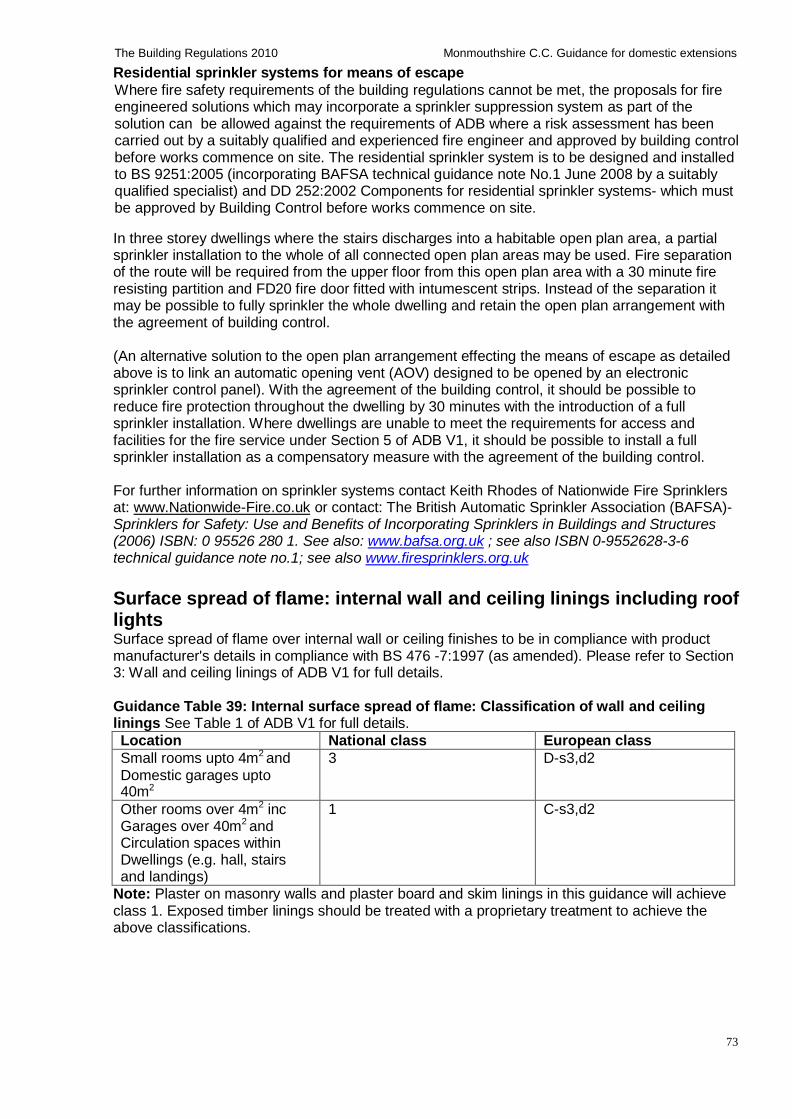
73
The Building Regulations 2010 Monmouthshire C.C. Guidance for domestic extensions
Residential sprinkler systems for means of escape
Where fire safety requirements of the building regulations cannot be met, the proposals for fire engineered solutions which may incorporate a sprinkler suppression system as part of the solution can be allowed against the requirements of ADB where a risk assessment has been carried out by a suitably qualified and experienced fire engineer and approved by building control before works commence on site. The residential sprinkler system is to be designed and installed to BS 9251:2005 (incorporating BAFSA technical guidance note No.1 June 2008 by a suitably qualified specialist) and DD 252:2002 Components for residential sprinkler systems- which must be approved by Building Control before works commence on site.
In three storey dwellings where the stairs discharges into a habitable open plan area, a partial sprinkler installation to the whole of all connected open plan areas may be used. Fire separation of the route will be required from the upper floor from this open plan area with a 30 minute fire resisting partition and FD20 fire door fitted with intumescent strips. Instead of the separation it may be possible to fully sprinkler the whole dwelling and retain the open plan arrangement with the agreement of building control.
(An alternative solution to the open plan arrangement effecting the means of escape as detailed above is to link an automatic opening vent (AOV) designed to be opened by an electronic sprinkler control panel). With the agreement of the building control, it should be possible to reduce fire protection throughout the dwelling by 30 minutes with the introduction of a full sprinkler installation. Where dwellings are unable to meet the requirements for access and facilities for the fire service under Section 5 of ADB V1, it should be possible to install a full sprinkler installation as a compensatory measure with the agreement of the building control.
For further information on sprinkler systems contact Keith Rhodes of Nationwide Fire Sprinklers at: www.Nationwide-Fire.co.uk or contact: The British Automatic Sprinkler Association (BAFSA)- Sprinklers for Safety: Use and Benefits of Incorporating Sprinklers in Buildings and Structures (2006) ISBN: 0 95526 280 1. See also: www.bafsa.org.uk ; see also ISBN 0-9552628-3-6 technical guidance note no.1; see also www.firesprinklers.org.uk
Surface spread of flame: internal wall and ceiling linings including roof lights Surface spread of flame over internal wall or ceiling finishes to be in compliance with product manufacturer's details in compliance with BS 476 -7:1997 (as amended). Please refer to Section 3: Wall and ceiling linings of ADB V1 for full details.
Guidance Table 39: Internal surface spread of flame: Classification of wall and ceiling linings See Table 1 of ADB V1 for full details.
Location National class European class
Small rooms upto 4m2 and
Domestic garages upto 40m2
3 D-s3,d2
Other rooms over 4m2 inc Garages over 40m2 and Circulation spaces within Dwellings (e.g. hall, stairs and landings)
1 C-s3,d2
Note: Plaster on masonry walls and plaster board and skim linings in this guidance will achieve class 1. Exposed timber linings should be treated with a proprietary treatment to achieve the above classifications.
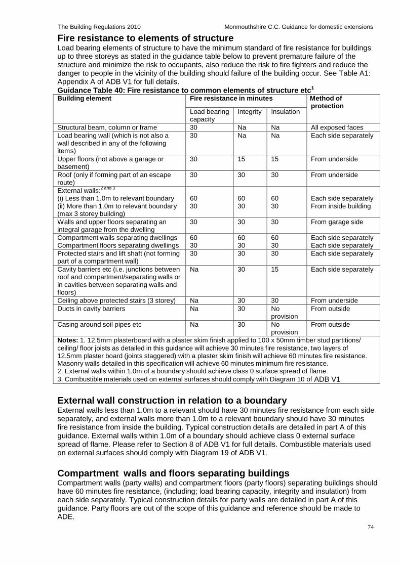
74
The Building Regulations 2010 Monmouthshire C.C. Guidance for domestic extensions
Fire resistance to elements of structure Load bearing elements of structure to have the minimum standard of fire resistance for buildings up to three storeys as stated in the guidance table below to prevent premature failure of the structure and minimize the risk to occupants, also reduce the risk to fire fighters and reduce the danger to people in the vicinity of the building should failure of the building occur. See Table A1: Appendix A of ADB V1 for full details. Guidance Table 40: Fire resistance to common elements of structure etc1
Building element Fire resistance in minutes Method of protection
Load bearing capacity
Integrity Insulation
Structural beam, column or frame 30 Na Na All exposed faces
Load bearing wall (which is not also a wall described in any of the following items)
30 Na Na Each side separately
Upper floors (not above a garage or basement)
30 15 15 From underside
Roof (only if forming part of an escape route)
30 30 30 From underside
External walls:2 and 3
(i) Less than 1.0m to relevant boundary (ii) More than 1.0m to relevant boundary (max 3 storey building)
60 30
60 30
60 30
Each side separately From inside building
Walls and upper floors separating an integral garage from the dwelling
30 30 30 From garage side
Compartment walls separating dwellings Compartment floors separating dwellings
60 30
60 30
60 30
Each side separately Each side separately
Protected stairs and lift shaft (not forming part of a compartment wall)
30 30 30 Each side separately
Cavity barriers etc (i.e. junctions between roof and compartment/separating walls or in cavities between separating walls and floors)
Na 30 15 Each side separately
Ceiling above protected stairs (3 storey) Na 30 30 From underside
Ducts in cavity barriers Na 30 No provision
From outside
Casing around soil pipes etc Na 30 No provision
From outside
Notes: 1. 12.5mm plasterboard with a plaster skim finish applied to 100 x 50mm timber stud partitions/
ceiling/ floor joists as detailed in this guidance will achieve 30 minutes fire resistance, two layers of 12.5mm plaster board (joints staggered) with a plaster skim finish will achieve 60 minutes fire resistance. Masonry walls detailed in this specification will achieve 60 minutes minimum fire resistance. 2. External walls within 1.0m of a boundary should achieve class 0 surface spread of flame.
3. Combustible materials used on external surfaces should comply with Diagram 10 of ADB V1
External wall construction in relation to a boundary External walls less than 1.0m to a relevant should have 30 minutes fire resistance from each side separately, and external walls more than 1.0m to a relevant boundary should have 30 minutes fire resistance from inside the building. Typical construction details are detailed in part A of this guidance. External walls within 1.0m of a boundary should achieve class 0 external surface spread of flame. Please refer to Section 8 of ADB V1 for full details. Combustible materials used on external surfaces should comply with Diagram 19 of ADB V1.
Compartment walls and floors separating buildings Compartment walls (party walls) and compartment floors (party floors) separating buildings should have 60 minutes fire resistance, (including; load bearing capacity, integrity and insulation) from each side separately. Typical construction details for party walls are detailed in part A of this guidance. Party floors are out of the scope of this guidance and reference should be made to ADE.
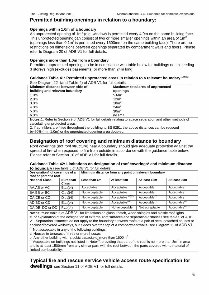
75
The Building Regulations 2010 Monmouthshire C.C. Guidance for domestic extensions
Permitted building openings in relation to a boundary:
Openings within 1.0m of a boundary
An unprotected opening of 1m2 (e.g. window) is permitted every 4.0m on the same building face. This unprotected opening can consist of two or more smaller openings within an area of 1m2
(openings less than 0.1m2 is permitted every 1500mm on the same building face). There are no restrictions on dimensions between openings separated by compartment walls and floors. Please refer to Diagram 20 of ADB V1 for full details.
Openings more than 1.0m from a boundary Permitted unprotected openings to be in compliance with table below for buildings not exceeding 3 storeys high (excludes basements) or more than 24m long.
Guidance Table 41: Permitted unprotected areas in relation to a relevant boundary 1and2
See Diagram 22 (and Table 4) of ADB V1 for full details Minimum distance between side of building and relevant boundary
Maximum total area of unprotected openings
1.0m 2.0m 3.0m 4.0m 5.0m 6.0m
5.6m2
12m2
18m2
24m2
30m2
no limit
Notes:1. Refer to Section 9 of ADB V1 for full details relating to space separation and other methods of
calculating unprotected areas. 2. If sprinklers are fitted throughout the building to BS 9251, the above distances can be reduced by 50% (min 1.0m) or the unprotected opening area doubled.
Designation of roof covering and minimum distance to boundary Roof coverings (not roof structure) near a boundary should give adequate protection against the spread of fire when exposed to fire from outside in accordance with the guidance table below. Please refer to Section 10 of ADB V1 for full details.
Guidance Table 42: Limitations on designation of roof coverings* and minimum distance to boundary (see table 5 of ADB V1 for full details). Designation# of coverings of a roof or part of a roof
Minimum distance from any point on relevant boundary
National Class European Class
Less than 6m At least 6m At least 12m At least 20m
AA.AB or AC Broof(t4) Acceptable Acceptable Acceptable Acceptable
BA.BB or BC Croof(t4) Not acceptable Acceptable Acceptable Acceptable
CA.CB or CC Droof(t4) Not acceptable (1)(2) Acceptable (1) Acceptable Acceptable
AD.BD or CD Eroof(t4) Not acceptable (1)(2) Acceptable
(1) Acceptable Acceptable
(1)
DA.DB, DC or DD Froof(t4) Not acceptable Not acceptable Not acceptable Acceptable(1)(2)
Notes: *See table 5 of ADB V1 for limitations on glass, thatch, wood shingles and plastic roof lights #For explanation of the designation of external roof surfaces and separation distances see table 5 of ADB V1. Separation distances do not apply to the boundary between roofs of a pair of semi detached houses or
enclosed/covered walkways, but it does over the top of a compartment walls- see Diagram 11 of ADB V1 (1)
Not acceptable in any of the following buildings: a. Houses in terraces of three or more houses
b. Any other building with a cubic capacity of more than 1500m3
(2) Acceptable on buildings not listed in Note
(1), providing that part of the roof is no more than 3m
2 in area
and is at least 1500mm from any similar part, with the roof between the parts covered with a material of limited combustibility.
Typical fire and rescue service vehicle access route specification for dwellings see Section 11 of ADB V1 for full details.
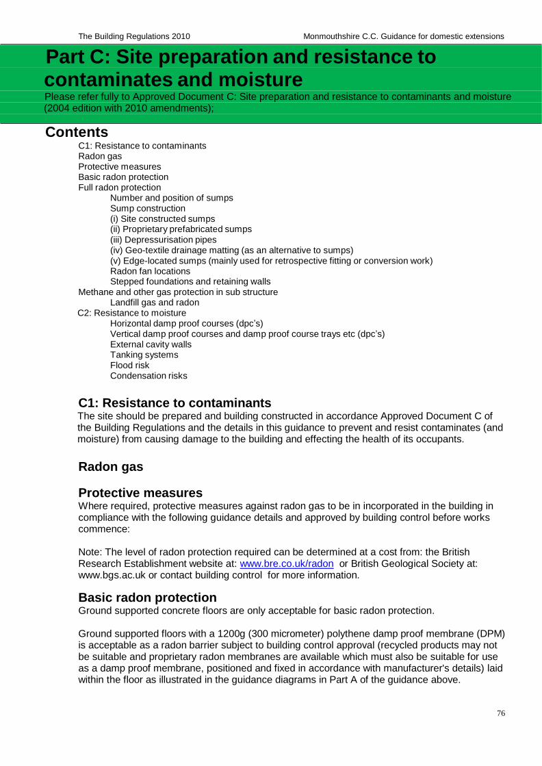
76
The Building Regulations 2010 Monmouthshire C.C. Guidance for domestic extensions
Part C: Site preparation and resistance to contaminates and moisture Please refer fully to Approved Document C: Site preparation and resistance to contaminants and moisture (2004 edition with 2010 amendments);
Contents C1: Resistance to contaminants Radon gas Protective measures Basic radon protection Full radon protection
Number and position of sumps Sump construction (i) Site constructed sumps (ii) Proprietary prefabricated sumps (iii) Depressurisation pipes (iv) Geo-textile drainage matting (as an alternative to sumps) (v) Edge-located sumps (mainly used for retrospective fitting or conversion work) Radon fan locations Stepped foundations and retaining walls
Methane and other gas protection in sub structure Landfill gas and radon
C2: Resistance to moisture Horizontal damp proof courses (dpc’s) Vertical damp proof courses and damp proof course trays etc (dpc’s) External cavity walls Tanking systems Flood risk Condensation risks
C1: Resistance to contaminants The site should be prepared and building constructed in accordance Approved Document C of the Building Regulations and the details in this guidance to prevent and resist contaminates (and moisture) from causing damage to the building and effecting the health of its occupants.
Radon gas
Protective measures Where required, protective measures against radon gas to be in incorporated in the building in compliance with the following guidance details and approved by building control before works commence:
Note: The level of radon protection required can be determined at a cost from: the British Research Establishment website at: www.bre.co.uk/radon or British Geological Society at: www.bgs.ac.uk or contact building control for more information.
Basic radon protection Ground supported concrete floors are only acceptable for basic radon protection.
Ground supported floors with a 1200g (300 micrometer) polythene damp proof membrane (DPM) is acceptable as a radon barrier subject to building control approval (recycled products may not be suitable and proprietary radon membranes are available which must also be suitable for use as a damp proof membrane, positioned and fixed in accordance with manufacturer's details) laid within the floor as illustrated in the guidance diagrams in Part A of the guidance above.
77
The Building Regulations 2010 Monmouthshire C.C. Guidance for domestic extensions
To prevent damage of the radon barrier, it should be installed at a later stage of construction - and sealed with gas proof tape to strips of membrane already built into the walls, or use a proprietary reinforced radon barrier/damp proof membrane. Any damaged areas to be repaired with radon membrane and sealed with two strips of gas proof tape with 150mm minimum laps.
Full radon protection Full radon protection is to be achieved by the provision of a continuous radon proof barrier (which must also be suitable as a damp proof membrane as detailed in the guidance diagrams in Part A of the guidance above) over the foot print of the building, continuing through the external/cavity walls, together with suspended beam and block floors or cast in-situ reinforced concrete slabs with sumps and sub floor depressurisation pipes as illustrated in the ground floor diagrams below. In areas requiring full radon protection the floor needs to be suspended and supported on the cavity wall to prevent settlement of the ground floor and rupture of the radon proof barrier at the external wall junction. Also see guidance details above for prevention of damage and repair of radon membranes.
Number and position of sumps Clean permeable fill to be used in the sub floor make up, with a single radon sump suitable for a
single dwelling over an area of approximately 250m2 or for a distance of 15m from the sump. Sumps to be connected together in multi compartmented sub floor areas using a pipe work manifold and connected to an external or internal fan, or vent openings/ducts formed through sub walls.
Sump construction
(i) Site constructed sumps Site constructed sumps are typically 600mm x 600mm square x 400mm deep, constructed using bricks laid in a honeycomb bond so as to form a box around the end of the pipe, the top of the box is covered with a paving slab.To avoid subsequent collapse when compacting fill around the sump, mortar should be used for horizontal joints. However, it is essential that all vertical joints are left open. Further details are available on the BRE website at: www.bre.co.uk/radon
(ii) Proprietary prefabricated sumps
Prefabricated sumps used as an alternative to brick construction should be installed in accordance with manufacturer's details.
(iii) Depressurisation pipes The pipe from the sump needs to be 110mm diameter Upvc with joints using standard couplings which are sealed and airtight. The pipe needs to leave the building so that it could be coupled to a fan mounted on the external wall. The pipe should terminate about 100mm from the external wall, and located at the rear of the house or at a re-entrant corner where subsequent installation of a boxed-in fan and vertical stack will be least obtrusive. until such time as a fan is installed, the pipe should be capped off 300mm above ground level to prevent vermin and rain penetration and capped off with an access plug and sign identifying radon pipe work fixed to wall above capping.
(iv) Geo-textile drainage matting (as an alternative to sumps)
Geo-textile drainage matting to be laid beneath the slab and connected to an extract pipe to provide a sump in accordance with manufacturer's details.
(v) Edge-located sumps (mainly used for retrospective fitting or conversion work) Edge-located mini-sumps can be used instead of centrally located sump in accordance with details available on the BRE web site at: www.bre.co.uk/radon which must be agreed with building control before works commence on site. Edge- located sumps are typically constructed by excavating a hole 400 x 400 x 400mm in the hardcore or fill beneath the dwelling alongside the perimeter wall to form an open area around the end of the extract pipe. fix 600 x 600mm paving slab or similar over sump to provide permanent formwork to support the floor slab (or make good existing cast in-situ floor slabs where sumps are fitted retrospectively). Seal
78
The Building Regulations 2010 Monmouthshire C.C. Guidance for domestic extensions
the pipe where it passes through the wall. Prefabricated sumps or site constructed sumps detailed above can also be used as edge-located sumps. (Concrete floor slabs to be reinforced over sumps if required by building control)
Radon fan locations When required, the fan should be positioned with the outlet well away from windows, doors and ventilation grilles and discharging just above eaves level. Low-level discharge is permitted if there are no openings or vents close by. To avoid penetrating the radon-proof floor membrane, the pipe should be taken through the wall, not up through the floor. The pipe work can be installed in ducts inside the house and connected as close as possible to the roof space fan and outlet terminating out through the roof using proprietary roof vent and flashing system- 900mm above any roof opening or vent that is within 3.0m of the terminal.
Stepped foundations and retaining walls Where possible, stepped foundations should be avoided, as they complicate the achievement of radon protection using only sealing techniques. It may prove less expensive to excavate around the house to provide a ventilated space, than to try to build into the hillside and seal all the faces of the building which are below ground level.
Further details
Guidance on protective measures against Radon gas are available on the BRE web site at: www.bre.co.uk/radon
Methane and other gas protection in sub structure Protection is to be provided in the sub structure in compliance with a specialists design and in the following circumstances:
If within 250m of a landfill site. (The Environment Agency’s policy on building development on or near landfill sites should be followed).
On a site containing biodegradable substances (including made up ground or fill); or subject to use that could have petrol oil or solvent spillages; or naturally occurring methane, carbon dioxide and other hazardous gases (e.g. hydrogen sulfide).
Further information on protective measures for methane and other ground gases is
available in the BRE publication 'Protective measures for housing on gas contaminated land 2001' which is available at a cost from: www.brebookshop.com
Risk assessments, ground investigations and any necessary remedial works should be carried out by a specialist in accordance with ADC which should be approved by Building Control/Environmental Health Department before works commence on
Landfill gas and radon Building works located on or adjacent to a landfill site or old coalfield may require additional precautions to a specialists design to deal with methane which exceed those required for radon, so where both methane and radon are present, methane-protective measures should be applied, and only intrinsically safe (non-sparking) fans and switchgear should be used.
C2: Resistance to moisture The walls, floor, and roof of the building should be constructed in accordance with ADC and the details/diagrams in this guidance to prevent and resist the passage of moisture into the building.
Horizontal damp proof courses (dpc’s) Horizontal damp proof course (dpc) and dpc trays with weep holes at 900mm ctrs to be provided 150mm above external ground level continuous with and sealed to the floor damp proof membrane (dpm) and radon/ dpc tray to prevent the ingress of moisture into the building.
79
The Building Regulations 2010 Monmouthshire C.C. Guidance for domestic extensions
Vertical damp proof courses and damp proof course trays etc (dpc’s)
Stepped and horizontal dpc/cavity trays are to be provided over all openings, roof abutments/ projections and over existing walls with different construction or materials. Install vertical dpc or proprietary insulated cavity closers at all closings, returns, abutments to cavity work and openings etc to prevent the ingress of moisture into the building.
External cavity walls
50mm minimum wide clear continuous cavity should extend the full height and width between the internal and external wall leafs bridged only by wall ties, cavity trays, cavity barriers, fire stops and cavity closures. (where a cavity is to be partially filled, the residual cavity should not be less than 50mm wide- unless the product has a British Board of Agreement (BBA or other approved third party accreditation) for use and approved by building control). The cavity should be carried down at least 225mm below damp course level at ground floor level to protect the inner wall leaf and damp proof (cavity) trays should be at least 150mm deep as diagrams/details in this guidance.
Tanking systems providing either barrier, structural or drained protection to the building must be assessed, designed and installed for the particular project in compliance with BS 8102: 2009 Code of Practice for Protection of Below Ground Structures Against Water from The Ground. Tanking systems can be installed internally or externally in accordance with a tanking specialist's details.
The illustrated tanking section details in this guidance are suggested details only and actual details must be approved by building control before works commence on site. Forms of tanking include: bonded sheet materials; liquid applied membranes; mastic asphalt, drained cavity membranes and cementitious crystallization and cementitious multi coat renders.
Suitable tanking systems to have British Board of Agreement (BBA or other approved third party) accreditation and individually assessed by a tanking specialist as suitable for the proposed situation. Tanking systems above ground should be vapour permeable to prevent condensation problems within the building and prevent mould growth.
Tanking systems must be designed/installed/applied by a tanking specialist for the particular project in compliance with tanking manufacturer's details and where necessary additional measures taken to prevent radon gas and other such ground gases and contaminates from entering the building.
Tanking systems to be properly connected to and made continuous with wall damp proof courses/radon dpc trays. Perforation of the tanking system by service entry pipes etc should be avoided or carried out strictly in accordance with the tanking manufacturer's details.
Flood risk
Flood risk should be assessed and precautions carried out in compliance with paragraph 0.8 of ADC
Condensation risks The technical details and diagrams in this guidance document should be read in conjunction with the BRE publication 'Thermal Insulation Avoiding Risks', which explains the technical risks and condensation risks which may be associated with meeting the building regulation requirements for thermal insulation for the major elements of the building. A copy of the publication can be obtained from: www.brebookshop.com
80
The Building Regulations 2010 Monmouthshire C.C. Guidance for domestic extensions
Part D: Toxic substances Please refer fully to Approved Document D: Toxic substances (1992 with 2002 and 2010 amendments)
If insulating material is inserted into a cavity in a cavity wall -precautions must be taken to prevent the subsequent permeation of any toxic fumes from that material into any part of the building occupied by people.
The suitability of the cavity wall for filling must be assessed before the works is carried out by an insulation specialist in accordance with BS 8208: Part 1: 1985 and the insulation system must be British Board of Agreement (BBA or other third party) accredited.
The insulation specialist carrying out the work must hold or operate under a current BSI Certificate of Registration of Assessed Capability for the work being carried out.
The insulation material must be in accordance with BS 5617: 1985 and the installation must be in accordance with BS 5618: 1985
The Installation of urea-formaldehyde (UF) in cavity walls is to be carried out in compliance with paragraphs 1.1 — 1.2 of ADD1
81
The Building Regulations 2010 Monmouthshire C.C. Guidance for domestic extensions
Part E: Resistance to passage of sound Please refer fully to Approved Document E: Resistance to the passage of sound (2003 with 2004 and
2010 amendments);
New party walls and floors in new extension Sound insulation details for new party walls to be carried out in accordance with the relevant details in ADE Section 2 and floors to be carried out in accordance with the relevant details contained within Section 2 of this guidance and ADE Section 3.
Please note that the Party Wall Act may be applicable to works to party walls (see guidance in general information above)
New Internal walls and floors in new extension Sound insulation details between internal walls and floors separating bedrooms or a room containing a WC and other rooms to be carried out in accordance with the relevant details contained within Section 2 of this guidance and ADE Section 5.
Pre completion sound testing
Where new party walls or party floors are constructed, pre-completion sound testing is to be carried out to demonstrate compliance with ADE Section 1 and as follows:
Pre completion sound testing is to be carried out by a suitably qualified person or specialist with appropriate third party accreditation (UKAS or ANC registration) to demonstrate compliance with ADE1, and copy of test results sent to building control.
Remedial works and re-testing
Remedial works and re-testing will be required where the test has failed, in compliance with Section 1 of ADE
Exemptions and relaxations If the requirements of the building regulations will unacceptably alter the character or appearance of a historic/listed building/ancient monument or building within a conservation area, then the requirements may be exempt or relaxed to what is reasonably practical or acceptable, ensuring that any exemption or relaxation would not increase the risk of deterioration of the building fabric or fittings in consultation with the local planning authorities conservation officer (before works commence) For further information see ADE and contact your local authority planning department
82
The Building Regulations 2010 Monmouthshire C.C. Guidance for domestic extensions
Part F: Ventilation Please refer fully to Approved Document F: Ventilation (2010 edition with further 2010 amendments)
Contents Purge (natural) ventilation Mechanical extract ventilation and fresh air inlets for rooms without purge ventilation Background ventilation Mechanical extract ventilation rates Ventilation systems for basements Ventilation of a habitable room through another room or conservatory General requirements for mechanical extract ventilation
Part F: Ventilation
Purge (natural) ventilation
Purge (natural) ventilation to be provided to all habitable rooms equal to 1/20th (5%) floor area. The 1/20th applies where the external windows/doors open more than 30 degrees and is increased to 1/10th (10%) of the floor area where the windows opens between 15 - 30 degrees. Window openings which open less than 15 degrees is not suitable for purge ventilation and alternative ventilation details are required as detailed below (in compliance section 5 and Appendix B of ADF1). Purge ventilation openings to habitable rooms to be typically located 1.75m above floor level. The area of external windows, roof windows and doors should not exceed 25% of the usable internal floor area otherwise SAP calculations may be required from a suitably qualified person to confirm design flexibility.
Unprotected openings (glazed window and door openings) should not exceed the permitted areas in relation to a boundary in compliance with Part B of this guidance.
Means of escape windows to be fitted with proprietary hinges to open to the minimum required clear width of 450mm. Escape windows must have minimum clear opening casement dimensions of 0.33m² and 450mm (typically 450mm wide x 750mm high), located within 800-1100mm above floor level to all bedrooms and habitable rooms at 1st floor level and inner habitable rooms on the ground floor. Windows above the ground floor storey and within 800mm of floor level are to be provided with containment/ guarding/ proprietary catches which should be removable (child proof) in the event of a fire. Where escape windows cannot be achieved, direct access to a protected stairs (or protected route to inner rooms) is acceptable in compliance with ADB V1- par 2.6 (a) or (b).
Mechanical extract ventilation and fresh air inlets for rooms without purge ventilation Mechanical extract ventilation and fresh air inlet are required for habitable rooms without purge (natural) ventilation which must designed by a ventilation specialist having a minimum of 4 air changes per hour and manually controlled in compliance section 5 of ADF1. This system can incorporate heat recovery if required. Note: means of escape windows are required to all bedrooms and habitable rooms at 1st floor level and inner habitable rooms on the ground floor in accordance with the guidance details above.
Background ventilation
Background ventilation to be provided equivalent to 8000mm² to habitable rooms and 2500mm2
to wet rooms via operable hit and miss vents into frames (or two stage security catches fitted to operable windows if agreed with building control). Fans and background vents fitted in the same room should be a minimum of 0.5m apart.
83
The Building Regulations 2010 Monmouthshire C.C. Guidance for domestic extensions
Mechanical extract ventilation rates
Mechanical ventilation is to be provided to the rooms listed below directly ducted to the outside air equivalent to the following rates.
Kitchen 30 litres per second over hob or 60 litres elsewhere Utility room 30 litres per second Bathroom 15 litres per second (including shower rooms and en-suites) Toilet 6 litres per second W/C (with or without a window)
Ventilation systems for basements To be carried out in compliance with Paragraphs 5.11- 5.13 of ADF1
Ventilation of a habitable room through another room or conservatory
To be carried out in compliance with Paragraphs 5.14- 5.16 of ADF1 General requirements for mechanical extract ventilation Mechanical ventilation to rooms without operable windows to be linked to light operation, independent switch or PIR and have 15 minutes overrun and a 10mm gap under the door for air supply. Fans must not be installed in rooms containing open flue appliances unless the interaction of mechanical ventilation and open flue heating appliances is checked and certified by an approved method and suitably qualified person as contained in ADJ.
Mechanical ventilation to be ducted in proprietary insulated ducts to outside through walls to proprietary vent or through roof space to proprietary a tile or soffit vent.
84
The Building Regulations 2010 Monmouthshire C.C. Guidance for domestic extensions
Part G: Sanitation, hot water safety and water efficiency Please refer fully to Approved Document G: Sanitation, hot water safety and water
efficiency (2010 edition with further 2010 amendments)
Contents Wholesome hot and cold water supply Scale of provisions Wash basins and separation of w/c from any food preparation areas Water tanks/cisterns base Pumped small bore foul water drainage Vented and unvented hot water storage systems Safety valves, prevention of scalding and energy cut outs (see new dwellings) Discharge pipes from safety devices Solar water heating Electrical water heating Supply (Water Fittings) Regulations 1999 Insulation of pipe work to prevent freezing Commissioning certificates
Part G: Sanitation, hot water safety and water efficiency
Wholesome hot and cold water supply Sinks with wholesome hot and cold running water are to be provided in all food preparation areas, bathrooms to be fitted with either a bath or shower. Hot and cold water supplies to wash basins, baths, showers and sinks including external taps to have water from a wholesome water supply.
Hot taps should be located on left hand side (traditionally as most people are left handed it prevents people from unwittingly running the hot tap and burning themselves) .
Softened wholesome cold water should not be provided where drinking water is drawn off or to any sink where food is prepared.
Wholesome water supply to comply with The Water Supply (Water Quality) Regulations 2000 (SI2000/3148) and in Wales; The Water Supply (Water Quality) Regulations 2001 (SI2001/3911) and Annex1 of AD. Private water supplies to comply with The Private Water Supplies Regulations 2009 (SI 2090/3101) and in Wales; The Private Water Supplies (Wales) Regulations (SI 2010/66)
Scale of provisions Any dwelling house or flat must have at least one bathroom, with a fixed bath or shower, wash basin and wc in compliance with BS 6465. Hot taps should be located on left hand side. In new dwellings, wc should be located in the principle entrance storey.
Wash basins and separation of w/c from any food preparation areas Wash hand basins to be provided in all rooms containing a w/c (or in an adjacent room providing the room is not used to prepare food) and a door must separate the w/c and wash basin from any food preparation area in a dwelling.
Water tanks/cisterns base Water tanks/cisterns must have an adequate designed flat platform base to support the proposed loads.
Pumped small bore foul water drainage Pumped small bore foul water drainage from a toilet is only permitted if there is also access to a gravity draining toilet in the same dwelling. Proprietary pumped foul water macerator systems must have BBA or other approved accreditation and fitted in compliance with manufacturer's details to a suitable foul water drainage system.

85
The Building Regulations 2010 Monmouthshire C.C. Guidance for domestic extensions
Vented and unvented hot water storage systems
Vented and unvented hot water storage systems to be designed, installed, commissioned and tested by a suitably qualified heating engineer/specialists (unvented systems to be indelibly marked with information contained in paragraph 3.23 of ADG), in compliance with paragraphs 3.10- 3.27 of ADG. Copy of commissioning certificates to be issued to Building Control on completion of the works.
Safety valves, prevention of scalding and energy cut outs (see new dwellings)
Discharge pipes from safety devices Discharge pipes from safety devices should be 600mm max length, constructed of metal (or other material suitable for proposed temperatures to BS 7291- 1:2006) and connect to a Tundish fitted with a suitable air gap in compliance with the current 'Water Supply (Water Fittings) Regulations. Any discharge into the Tundish must be visible (and where the dwelling is occupied by visibly or physically impaired- the devise must be electronically operated able to warn of discharge).
Discharge pipes from Tundish should be at least 300mm in length and fixed vertically below Tundish-before connection to any bend or elbow and at a continuous fall of 1:200 thereafter until point of termination. Pipes from Tundish should be at least one pipe size larger than the outlet of the safety devise upto 9m in length (2x larger 9-18m and 3x larger 18-27m) and constructed of metal (or other material suitable for proposed temperatures to BS 7291- 1:2006).
Point of termination from discharge pipes can be either: (i) To a trapped gully - below grating - but above the water seal (ii) Downward discharges at low level- upto 100mm above external surfaces (car parks, hard standings, grassed areas etc) and fitted with proprietary wire guard to prevent contact. (iii)Discharges at high level into metal hopper and metal down pipes at least 3m from plastic guttering collecting the discharge. Note: visibility of discharge must be maintained at all times and discharges of hot water and steam should not come into contact with materials that could be damaged by such discharges.
Solar water heating
Solar water heating roof/wall panel systems to be factory made to BS EN 12976-1:2006, fitted with safety devices and an additional heating source to maintain an adequate water temperature and fitted in compliance with manufacturer's details. Solar water heating systems should comply with current European/ British/ Standards.
Electrical water heating Fixed electrical immersion heaters to BS EN 60335-2-73:2003, electrical instantaneous water heaters to BS EN 60335-2-35:2002, electrical storage water heaters to BS EN 60335-2-21:2003 and safety devices to be manufactured and installed in accordance with ADG, manufacturer's details and current European/ British/ Standards.
Supply (Water Fittings) Regulations 1999
All new water installations must be in compliance with the 'Supply (Water Fittings) Regulations 1999' for England and Wales, for the protection against frost and freezing, prevention of waste, misuse, undue consumption, contamination and erroneous measurement of a water supplier's mains water supply. A free copy of regulations can be downloaded from the HMSO website, or alternatively a hard copy of the new Regulations can be purchased directly from your local HMSO stationary office. The Regulations are Statutory Instrument No 1148 and the amendments are Statutory Instrument No 1506 both dated 1999.
86
The Building Regulations 2010 Monmouthshire C.C. Guidance for domestic extensions
Insulation of pipe work to prevent freezing
All hot and cold water service pipe work, tanks and cisterns should be located within the warm envelope of the building to prevent freezing.
Where hot and cold water service pipe work, tanks and cisterns are located in unheated spaces they should be insulated to prevent freezing in compliance with BS 6700 and BS 8558, and typically as follows: (i) All tanks and cisterns should be thermally insulated to prevent freezing with proprietary insulated systems in compliance with manufacturer's systems (insulation normally omitted from below tank where it benefits from heat in the heated area below). (ii) Pipe work should be insulated with proprietary insulated sleeves of phenolic/ polyosocyanurate/ polyurethane foam having a minimum wall thickness of 30mm for 15mm diameter pipes and 12mm for pipes 22mm diameter pipes, (or other approved) and fixed in accordance with manufacturer's details.
Incoming cold water supply service pipes should be at least 750mm below the ground level and other precautions should be carried out to prevent freezing and protect the pipe in accordance with the relevant Water Authorities requirements, which will require consent from the Water Authority before works commence.
Commissioning certificates
Commissioning certificates for fixed building services are required on completion with copy sent to building control
87
The Building Regulations 2010 Monmouthshire C.C. Guidance for domestic extensions
Part H: Drainage and waste disposal Please refer fully to Approved Document H: Drainage and waste disposal (2002 edition with 2010 amendments)
Contents H1: Foul and storm water drainage
Foul, rain and storm water drainage systems (single dwellings) Bedding and backfilling requirements for rigid and flexible pipes Guidance Diagram 39: Typical bedding detail for flexible pipes Guidance Diagram 40: Typical protection detail for pipes laid at shallow depths Pipes penetrating though walls Drain trenches near buildings Inspection chambers and gullies Guidance Table 43: Minimum dimensions for access fittings and inspection chambers Guidance Table 44: Minimum dimensions for manholes Guidance Table 45: Maximum spacing of access points in metres Foul water disposal Waste pipes Guidance Table 46: Waste pipe and trap design limits Soil and vent pipes (discharge stack) Guidance Table 47: Minimum diameters for discharge stacks Waste pipe connections to soil and vent pipes (discharge stack) - to prevent cross flow (i) Waste pipes up-to 65mm diameter (ii) Waste pipes over 65mm diameter (iii) Lowest waste pipe connection to soil and vent pipe Stub stacks Air admittance valves Air tightness and testing Pipes, fittings and joints should be capable of withstanding an air test of positive pressure of at Pumping installations
H2: Septic tanks, sewage treatment systems and cesspools Existing septic tank and effluent drainage Non mains foul drainage waste water treatment systems Septic tanks Sewage treatment systems Disposal of sewage from septic tanks and sewage treatment systems Drainage fields Drainage mounds Wetlands/reed beds Percolation tests Ground conditions Percolation test method Guidance Diagram 41: Typical section through a septic tank/sewage treatment system drainage field Guidance Diagram 42: Typical drainage field plan layout Cesspools
H3: Rainwater drainage and harvesting Rainwater gutters and down pipes Rainwater gutters and down pipe sizes and number to be suitable for roof area to be drained in Guidance Table 48: Gutter sizes and pipe outlet sizes for drainage of roof areas Rainwater/ grey water harvesting storage tanks and systems Surface water drainage around the building Rain/surface water disposal Existing soak-away New soak-away Guidance Diagram 43: New soakaway design Oil/fuel separators
H4: Building over or close to and connections to public sewers Building over or close to a Public Sewer Locating a public sewer The Build Over Process
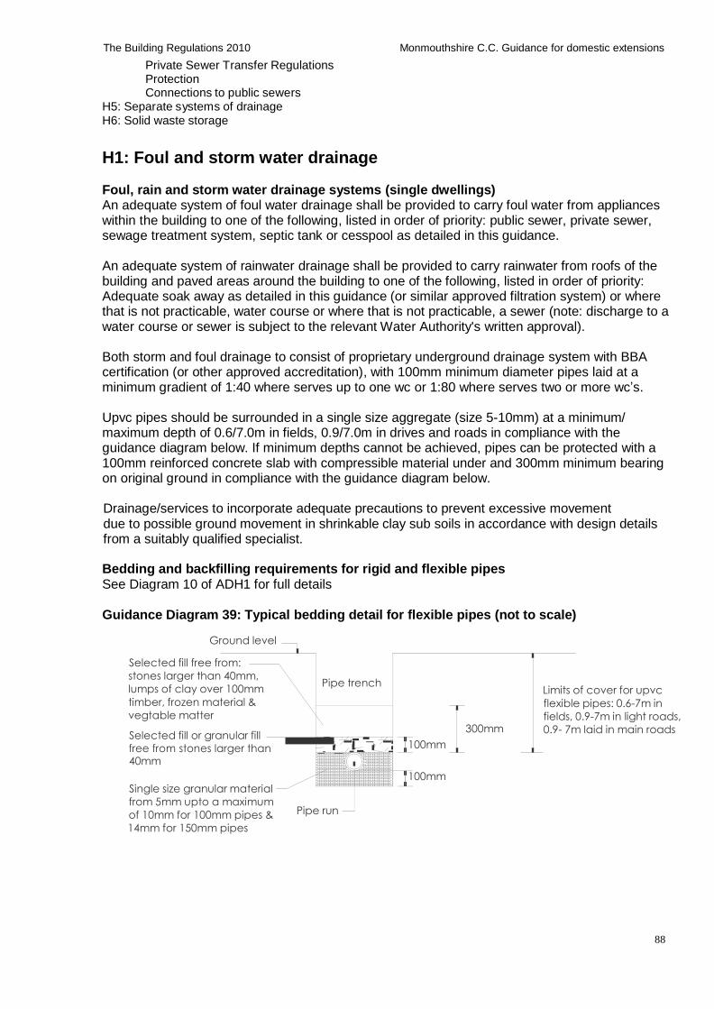
88
The Building Regulations 2010 Monmouthshire C.C. Guidance for domestic extensions
Private Sewer Transfer Regulations Protection Connections to public sewers
H5: Separate systems of drainage H6: Solid waste storage
H1: Foul and storm water drainage Foul, rain and storm water drainage systems (single dwellings) An adequate system of foul water drainage shall be provided to carry foul water from appliances within the building to one of the following, listed in order of priority: public sewer, private sewer, sewage treatment system, septic tank or cesspool as detailed in this guidance.
An adequate system of rainwater drainage shall be provided to carry rainwater from roofs of the building and paved areas around the building to one of the following, listed in order of priority: Adequate soak away as detailed in this guidance (or similar approved filtration system) or where that is not practicable, water course or where that is not practicable, a sewer (note: discharge to a water course or sewer is subject to the relevant Water Authority's written approval).
Both storm and foul drainage to consist of proprietary underground drainage system with BBA certification (or other approved accreditation), with 100mm minimum diameter pipes laid at a minimum gradient of 1:40 where serves up to one wc or 1:80 where serves two or more wc’s.
Upvc pipes should be surrounded in a single size aggregate (size 5-10mm) at a minimum/ maximum depth of 0.6/7.0m in fields, 0.9/7.0m in drives and roads in compliance with the guidance diagram below. If minimum depths cannot be achieved, pipes can be protected with a 100mm reinforced concrete slab with compressible material under and 300mm minimum bearing on original ground in compliance with the guidance diagram below.
Drainage/services to incorporate adequate precautions to prevent excessive movement due to possible ground movement in shrinkable clay sub soils in accordance with design details from a suitably qualified specialist.
Bedding and backfilling requirements for rigid and flexible pipes See Diagram 10 of ADH1 for full details
Guidance Diagram 39: Typical bedding detail for flexible pipes (not to scale)
Ground level
Selected fill free from:
stones larger than 40mm,
lumps of clay over 100mm
timber, frozen material &
vegtable matter
Selected fill or granular fill
Pipe trench
300mm
Limits of cover for upvc
flexible pipes: 0.6-7m in
fields, 0.9-7m in light roads,
0.9- 7m laid in main roads
free from stones larger than 40mm
Single size granular material
from 5mm upto a maximum
100mm
100mm
of 10mm for 100mm pipes &
14mm for 150mm pipes
Pipe run
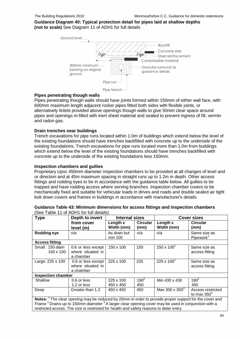
89
The Building Regulations 2010 Monmouthshire C.C. Guidance for domestic extensions
Guidance Diagram 40: Typical protection detail for pipes laid at shallow depths
(not to scale) See Diagram 11 of ADH1 for full details
Ground level
300mm minimum
bearing on original
ground
Backfill
Concrete slab
Steel reinforcement
Compressible material
Granular surround as
guidance details
Pipe run
Pipes penetrating though walls
Pipe trench
Pipes penetrating though walls should have joints formed within 150mm of either wall face, with 600mm maximum length adjacent rocker pipes fitted both sides with flexible joints, or alternatively lintels provided above openings though walls to give 50mm clear space around pipes and openings in-filled with inert sheet material and sealed to prevent ingress of fill, vermin and radon gas.
Drain trenches near buildings Trench excavations for pipe runs located within 1.0m of buildings which extend below the level of the existing foundations should have trenches backfilled with concrete up to the underside of the existing foundations. Trench excavations for pipe runs located more than 1.0m from buildings which extend below the level of the existing foundations should have trenches backfilled with concrete up to the underside of the existing foundations less 150mm.
Inspection chambers and gullies Proprietary Upvc 450mm diameter inspection chambers to be provided at all changes of level and or direction and at 45m maximum spacing in straight runs up to 1.2m in depth. Other access fittings and rodding eyes to be in accordance with the guidance table below. All gullies to be trapped and have rodding access where serving branches. Inspection chamber covers to be mechanically fixed and suitable for vehicular loads in drives and roads and double sealed air tight bolt down covers and frames in buildings in accordance with manufacturer's details.
Guidance Table 43: Minimum dimensions for access fittings and inspection chambers
(See Table 11 of ADH1 for full details)
Type Depth to invert Internal sizes Cover sizes
from cover level (m)
Length x Width (mm)
Circular (mm)
Length x Width (mm)
Circular (mm)
Rodding eye n/a As drain but min 100
n/a n/a Same size as
Pipework1
Access fitting
Small : 150 diam 150 x 100
0.6 or less except where situated in a chamber
150 x 100 150 150 x 1001
Same size as access fitting
Large: 225 x 100 0.6 or less except where situated in a chamber
Inspection chamber
225 x 100 225 225 x 1001
Same size as access fitting
Shallow 0.6 or less 1.2 or less
225 x 100 450 x 450
1902
450 Min 430 x 430 190
1
450
Deep Greater than 1.2 450 x 450 450 Max 300 x 3003
Access restricted to max 350
3
Notes: 1 The clear opening may be reduced by 20mm in order to provide proper support for the cover and
Frame 2 Drains up to 150mm diameter
3 A larger clear opening cover may be used in conjunction with a
restricted access. The size is restricted for health and safety reasons to deter entry
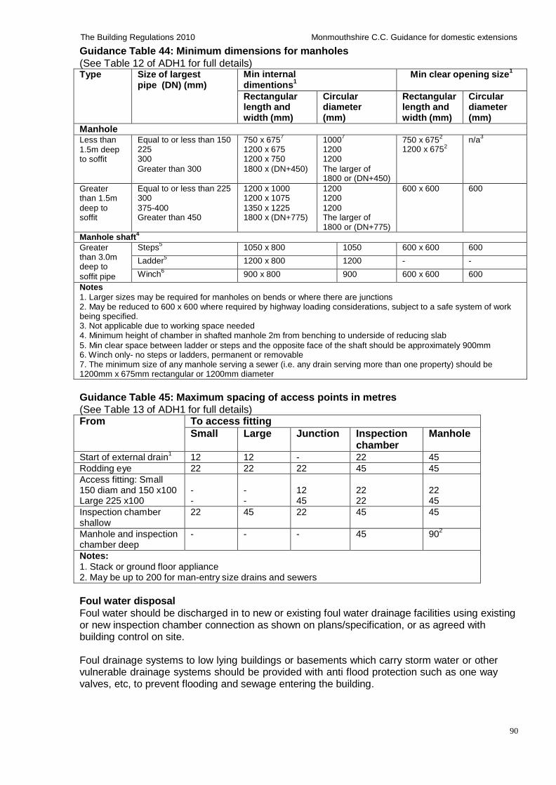
90
The Building Regulations 2010 Monmouthshire C.C. Guidance for domestic extensions
Guidance Table 44: Minimum dimensions for manholes
(See Table 12 of ADH1 for full details) Type Size of largest
pipe (DN) (mm) Min internal dimentions
1
Min clear opening size1
Rectangular length and width (mm)
Circular diameter (mm)
Rectangular length and width (mm)
Circular diameter (mm)
Manhole Less than 1.5m deep to soffit
Equal to or less than 150 225 300
Greater than 300
750 x 6757
1200 x 675 1200 x 750
1800 x (DN+450)
10007
1200 1200
The larger of 1800 or (DN+450)
750 x 6752
1200 x 6752
n/a3
Greater than 1.5m
deep to soffit
Equal to or less than 225 300
375-400 Greater than 450
1200 x 1000 1200 x 1075
1350 x 1225 1800 x (DN+775)
1200 1200
1200 The larger of 1800 or (DN+775)
600 x 600 600
Manhole shaft4
Greater than 3.0m deep to
soffit pipe
Steps5
1050 x 800 1050 600 x 600 600
Ladder5
1200 x 800 1200 - -
Winch6 900 x 800 900 600 x 600 600
Notes
1. Larger sizes may be required for manholes on bends or where there are junctions 2. May be reduced to 600 x 600 where required by highway loading considerations, subject to a safe system of work being specified. 3. Not applicable due to working space needed 4. Minimum height of chamber in shafted manhole 2m from benching to underside of reducing slab
5. Min clear space between ladder or steps and the opposite face of the shaft should be approximately 900mm 6. Winch only- no steps or ladders, permanent or removable 7. The minimum size of any manhole serving a sewer (i.e. any drain serving more than one property) should be 1200mm x 675mm rectangular or 1200mm diameter
Guidance Table 45: Maximum spacing of access points in metres
(See Table 13 of ADH1 for full details)
From To access fitting
Small Large Junction Inspection chamber
Manhole
Start of external drain1
12 12 - 22 45
Rodding eye 22 22 22 45 45
Access fitting: Small 150 diam and 150 x100 Large 225 x100
- -
- -
12 45
22 22
22 45
Inspection chamber shallow
22 45 22 45 45
Manhole and inspection chamber deep
- - - 45 902
Notes: 1. Stack or ground floor appliance 2. May be up to 200 for man-entry size drains and sewers
Foul water disposal
Foul water should be discharged in to new or existing foul water drainage facilities using existing or new inspection chamber connection as shown on plans/specification, or as agreed with building control on site.
Foul drainage systems to low lying buildings or basements which carry storm water or other vulnerable drainage systems should be provided with anti flood protection such as one way valves, etc, to prevent flooding and sewage entering the building.
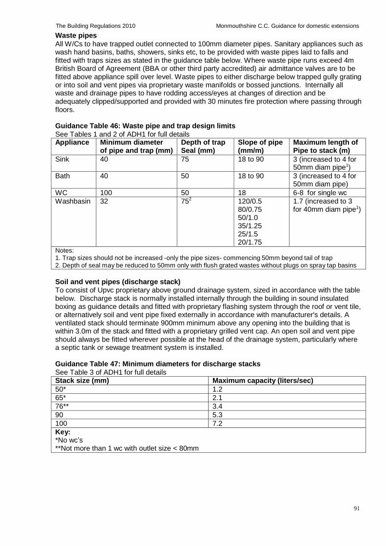
91
The Building Regulations 2010 Monmouthshire C.C. Guidance for domestic extensions
Waste pipes
All W/Cs to have trapped outlet connected to 100mm diameter pipes. Sanitary appliances such as wash hand basins, baths, showers, sinks etc, to be provided with waste pipes laid to falls and fitted with traps sizes as stated in the guidance table below. Where waste pipe runs exceed 4m British Board of Agreement (BBA or other third party accredited) air admittance valves are to be fitted above appliance spill over level. Waste pipes to either discharge below trapped gully grating or into soil and vent pipes via proprietary waste manifolds or bossed junctions. Internally all waste and drainage pipes to have rodding access/eyes at changes of direction and be adequately clipped/supported and provided with 30 minutes fire protection where passing through floors.
Guidance Table 46: Waste pipe and trap design limits
See Tables 1 and 2 of ADH1 for full details Appliance Minimum diameter
of pipe and trap (mm) Depth of trap Seal (mm)
Slope of pipe (mm/m)
Maximum length of Pipe to stack (m)
Sink 40 75 18 to 90 3 (increased to 4 for 50mm diam pipe1)
Bath 40 50 18 to 90 3 (increased to 4 for 50mm diam pipe)
WC 100 50 18 6-8 for single wc
Washbasin 32 752 120/0.5
80/0.75 50/1.0 35/1.25 25/1.5 20/1.75
1.7 (increased to 3 for 40mm diam pipe1)
Notes: 1. Trap sizes should not be increased -only the pipe sizes- commencing 50mm beyond tail of trap 2. Depth of seal may be reduced to 50mm only with flush grated wastes without plugs on spray tap basins
Soil and vent pipes (discharge stack) To consist of Upvc proprietary above ground drainage system, sized in accordance with the table below. Discharge stack is normally installed internally through the building in sound insulated boxing as guidance details and fitted with proprietary flashing system through the roof or vent tile, or alternatively soil and vent pipe fixed externally in accordance with manufacturer's details. A ventilated stack should terminate 900mm minimum above any opening into the building that is within 3.0m of the stack and fitted with a proprietary grilled vent cap. An open soil and vent pipe should always be fitted wherever possible at the head of the drainage system, particularly where a septic tank or sewage treatment system is installed.
Guidance Table 47: Minimum diameters for discharge stacks
See Table 3 of ADH1 for full details Stack size (mm) Maximum capacity (liters/sec)
50* 1.2
65* 2.1
76** 3.4
90 5.3
100 7.2
Key: *No wc’s **Not more than 1 wc with outlet size < 80mm
92
The Building Regulations 2010 Monmouthshire C.C. Guidance for domestic extensions
Waste pipe connections to soil and vent pipes (discharge stack) - to prevent cross flow (i) Waste pipes up-to 65mm diameter- opposed pipe connections (without swept entries) should be offset at least 110mm on a 100mm diameter stack and 250mm on a 150mm diameter stack, at a radius of 25mm or angle of 45 degrees- or alternatively a proprietary manifold fitted in accordance with manufacturer's details. (ii) Waste pipes over 65mm diameter- opposed pipe connections (with swept entries) should be offset at least 200mm irrespective of stack diameter (no connections are allowed within this 200mm zone), at a radius of 50mm or angle of 45 degrees. Unopposed connections may be at any position. (iii) Lowest waste pipe connection to soil and vent pipe- 450mm minimum distance is
required between centre line of waste pipe connection to soil and vent pipe and invert level of below ground drain, ensuring a 200mm minimum radius bend connects the soil and vent pipe to the drain.
Stub stacks To consist of 100mm diameter Upvc proprietary above ground drainage system, with wash basins/sinks connected to the sub stack within 2.0m of the invert level of the drain and the wc floor level is to be within 1.3m of the invert level of the drain.
Air admittance valves Proprietary air admittance valves fitted to sub stacks or soil and vent pipes should comply with BS EN 12380 and be installed in accordance with manufacturer's details, and valve is to be located above the spillover level of the highest appliance i.e. wash basin or sink. Valves installed internally should be located in sound insulated boxing, accessible for maintenance and clearance of blockages etc. and fitted with 225 x 75mm louvered vent. Valves should not be installed in dusty environments. An open vent should always be fitted wherever possible at the head of the drainage system, particularly where a septic tank or sewage treatment system is installed.
Air tightness and testing
Pipes, fittings and joints should be capable of withstanding an air test of positive pressure of at least 38mm water gauge for at least 3 minutes. Every trap should maintain a water seal of at least 25mm. Smoke testing should be used to identify defects where water test has failed. Note: smoke testing is not recommended for Upvc pipes.
Pumping installations Where gravity drainage is impractical, or protection is required against flooding due to surcharging in downstream sewers, pumped drainage solutions may be required - subject to building control approval.
Proprietary packaged pumping systems to consist of a watertight GRP/polyethylene chamber, lockable pedestrian/vehicle covers, pumps, high level alarm, preset automatic level control, float switch, non-return valve, discharge pipe and connections etc. Domestic sewage pump sets located within buildings should conform to BS EN 12050, designed in accordance with BS EN 12056-4 and installed in accordance with manufacturer’s details. Domestic sewage pump sets located outside buildings should be designed in accordance with BS EN 752-6 and installed in accordance with manufacturer’s details. Pumped installations must contain 24 hours inflow storage. The minimum daily discharge of foul drainage should be taken as 150 litres per person per day for domestic use. Auto-changeover duty/standby duplex (twin pumps) pump stations may be accepted as an alternative to 24 hours storage subject to approval by building control.
93
The Building Regulations 2010 Monmouthshire C.C. Guidance for domestic extensions
H2: Septic tanks, sewage treatment systems and cesspools Existing septic tank and effluent drainage
Where additional drainage effluent is to be connected to the existing septic tank/treatment system, it should be checked by specialist and sizes/condition of tank/system to be confirmed as suitable for treatment of additional effluent.
Non mains foul drainage waste water treatment systems Non mains drainage systems are to be used only where connection to the mains drainage system is not possible. Either a septic tank or sewage treatment system is to be installed as to suit specific ground conditions as agreed with Building Control. No septic tank/ sewage treatment system and associated tertiary (secondary) treatment is permitted by the Environment Agency in prescribed Zone 1 ground water source protection zones. Where no other option is feasible, the installation of a cesspool is to be agreed with Building Control and the Environment Agency.
Septic tanks
Septic tanks to consist of a watertight chamber (watertight from both sides to prevent the ingress of water and contain the effluent). The sewage is liquefied by anaerobic bacteria action in the absence of oxygen assisted by the natural formation of a surface scum or crust. Sludge settlement at the base of the tank must be removed annually (or more frequently if required). Discharge from tanks is to be taken to drainage fields, drainage mounds or wetlands/reed beds for secondary treatment as detailed in the guidance below.
Proprietary factory made septic tanks to be designed and constructed to BS EN 12566 and installed in accordance with manufacturer’s details, or
Non proprietary septic tanks constructed in situ to be designed and constructed to a drainage specialist’s design and approved by Building Control before the works commence on site. Typically, the tank consists of two chambers (the first being twice as large as the second) constructed using 150mm minimum thick reinforced concrete base C25P mix to BS 5328, 220mm thick engineering quality brickwork walls (or concrete), mortar mix 1:3 cement/sand ratio with water proof rending or suitable proprietary tanking system applied to both sides and designed heavy concrete roof structure. 100mm diameter Inlet and outlet ‘dip pipes’ is required and designed to prevent disturbance of the surface scum, inlet pipe laid at a flatter gradient for at least 12 meters before it enters the tank.
Septic tanks to be fitted with durable lockable lids or covers for emptying and cleaning, and inspection chamber fitted on the discharge side of tank for sampling of the effluent.
Septic tanks to be sited at least 7m from any habitable part of any building, preferably down slopes, within 30m of a suitable vehicle access for emptying and cleaning sludge which must not be taken through a dwelling or place of work and must not be a hazard to the building occupants. If the tank invert is more than 3.0m the 30m distance should be reduced.
Septic tank should have a minimum capacity of 2,700 litres for upto 4 users and increased by 180 litres for each additional user. (Recommended minimum size of septic tank to be 3,800 litres to accommodate discharges from washing machines/dishwashers etc). A notice plate must be fixed within the building and include the following information: Address of the property; location of the treatment system; description of the septic tank and effluent drainage installed; necessary maintenance to be carried out (including monthly checks of the apparatus and emptying of the tank every 12 months by a licensed contractor) and a statement that the owner is legally responsible to ensure that the system does not cause pollution, health hazard or nuisance.
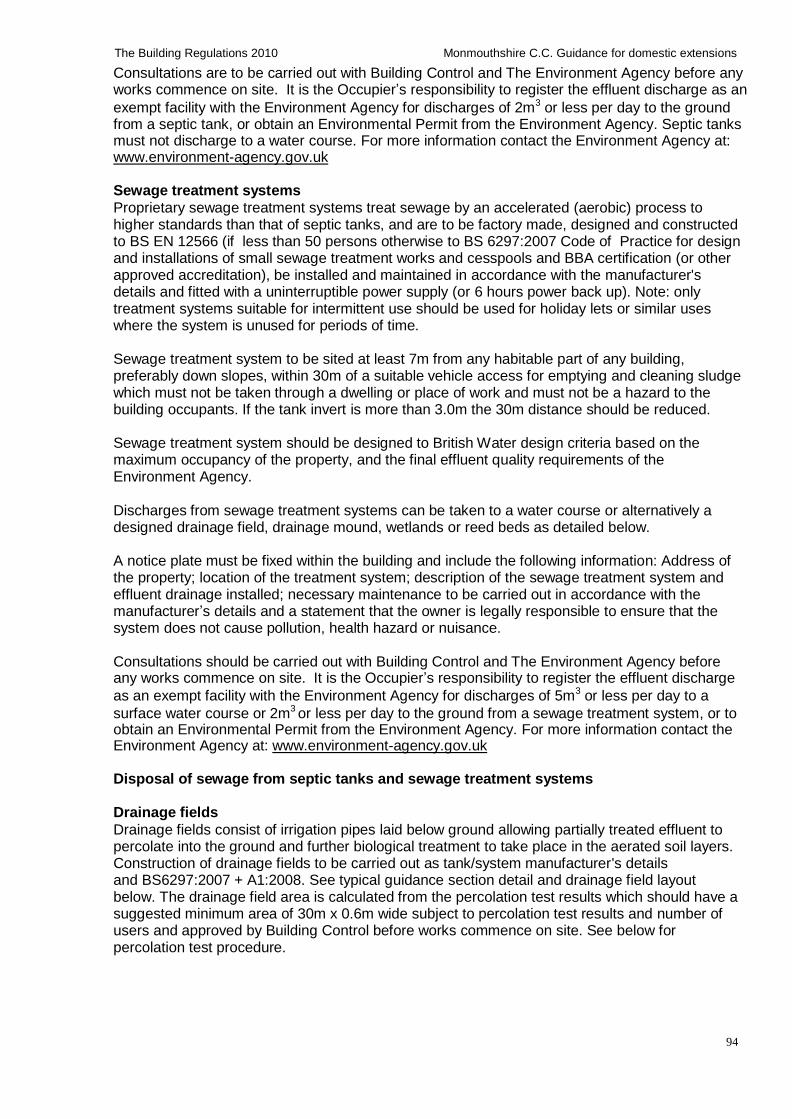
94
The Building Regulations 2010 Monmouthshire C.C. Guidance for domestic extensions
Consultations are to be carried out with Building Control and The Environment Agency before any works commence on site. It is the Occupier’s responsibility to register the effluent discharge as an
exempt facility with the Environment Agency for discharges of 2m3 or less per day to the ground from a septic tank, or obtain an Environmental Permit from the Environment Agency. Septic tanks must not discharge to a water course. For more information contact the Environment Agency at: www.environment-agency.gov.uk
Sewage treatment systems
Proprietary sewage treatment systems treat sewage by an accelerated (aerobic) process to higher standards than that of septic tanks, and are to be factory made, designed and constructed to BS EN 12566 (if less than 50 persons otherwise to BS 6297:2007 Code of Practice for design and installations of small sewage treatment works and cesspools and BBA certification (or other approved accreditation), be installed and maintained in accordance with the manufacturer's details and fitted with a uninterruptible power supply (or 6 hours power back up). Note: only treatment systems suitable for intermittent use should be used for holiday lets or similar uses where the system is unused for periods of time.
Sewage treatment system to be sited at least 7m from any habitable part of any building, preferably down slopes, within 30m of a suitable vehicle access for emptying and cleaning sludge which must not be taken through a dwelling or place of work and must not be a hazard to the building occupants. If the tank invert is more than 3.0m the 30m distance should be reduced.
Sewage treatment system should be designed to British Water design criteria based on the maximum occupancy of the property, and the final effluent quality requirements of the Environment Agency.
Discharges from sewage treatment systems can be taken to a water course or alternatively a designed drainage field, drainage mound, wetlands or reed beds as detailed below.
A notice plate must be fixed within the building and include the following information: Address of the property; location of the treatment system; description of the sewage treatment system and effluent drainage installed; necessary maintenance to be carried out in accordance with the manufacturer’s details and a statement that the owner is legally responsible to ensure that the system does not cause pollution, health hazard or nuisance.
Consultations should be carried out with Building Control and The Environment Agency before any works commence on site. It is the Occupier’s responsibility to register the effluent discharge
as an exempt facility with the Environment Agency for discharges of 5m3 or less per day to a
surface water course or 2m3 or less per day to the ground from a sewage treatment system, or to obtain an Environmental Permit from the Environment Agency. For more information contact the Environment Agency at: www.environment-agency.gov.uk
Disposal of sewage from septic tanks and sewage treatment systems Drainage fields
Drainage fields consist of irrigation pipes laid below ground allowing partially treated effluent to percolate into the ground and further biological treatment to take place in the aerated soil layers. Construction of drainage fields to be carried out as tank/system manufacturer's details and BS6297:2007 + A1:2008. See typical guidance section detail and drainage field layout below. The drainage field area is calculated from the percolation test results which should have a suggested minimum area of 30m x 0.6m wide subject to percolation test results and number of users and approved by Building Control before works commence on site. See below for percolation test procedure.
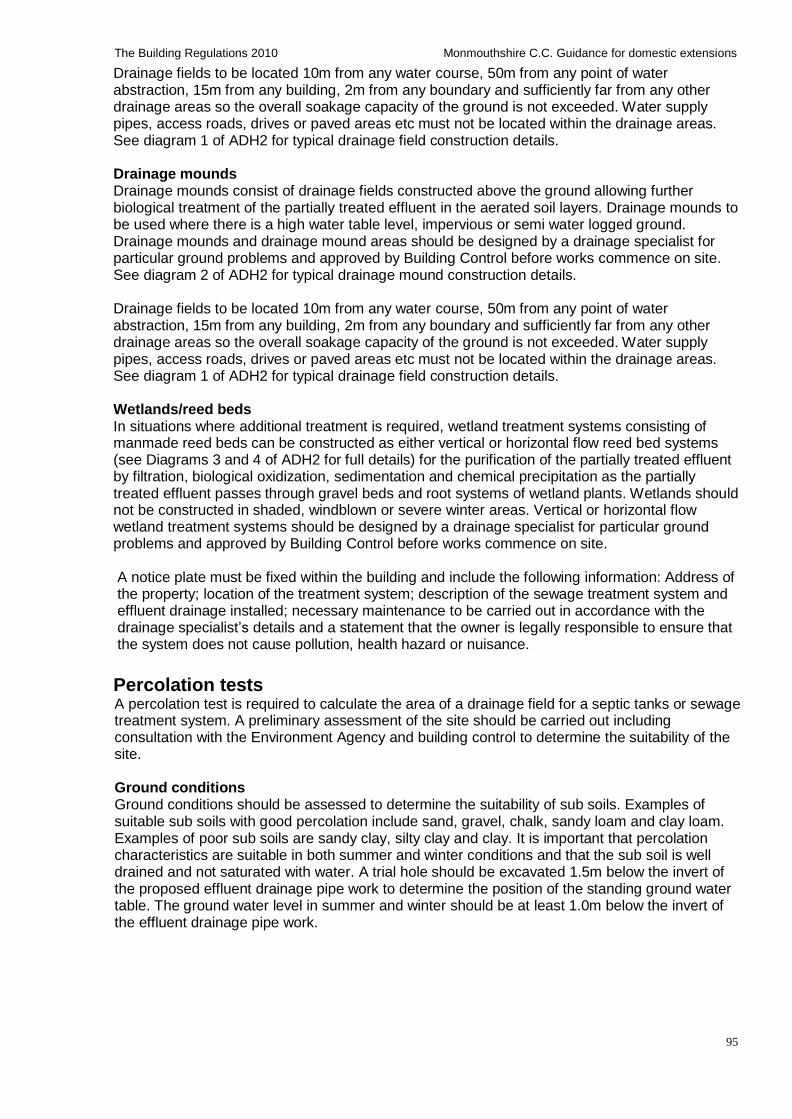
95
The Building Regulations 2010 Monmouthshire C.C. Guidance for domestic extensions
Drainage fields to be located 10m from any water course, 50m from any point of water abstraction, 15m from any building, 2m from any boundary and sufficiently far from any other drainage areas so the overall soakage capacity of the ground is not exceeded. Water supply pipes, access roads, drives or paved areas etc must not be located within the drainage areas. See diagram 1 of ADH2 for typical drainage field construction details.
Drainage mounds Drainage mounds consist of drainage fields constructed above the ground allowing further biological treatment of the partially treated effluent in the aerated soil layers. Drainage mounds to be used where there is a high water table level, impervious or semi water logged ground. Drainage mounds and drainage mound areas should be designed by a drainage specialist for particular ground problems and approved by Building Control before works commence on site. See diagram 2 of ADH2 for typical drainage mound construction details.
Drainage fields to be located 10m from any water course, 50m from any point of water abstraction, 15m from any building, 2m from any boundary and sufficiently far from any other drainage areas so the overall soakage capacity of the ground is not exceeded. Water supply pipes, access roads, drives or paved areas etc must not be located within the drainage areas. See diagram 1 of ADH2 for typical drainage field construction details.
Wetlands/reed beds In situations where additional treatment is required, wetland treatment systems consisting of manmade reed beds can be constructed as either vertical or horizontal flow reed bed systems (see Diagrams 3 and 4 of ADH2 for full details) for the purification of the partially treated effluent by filtration, biological oxidization, sedimentation and chemical precipitation as the partially treated effluent passes through gravel beds and root systems of wetland plants. Wetlands should not be constructed in shaded, windblown or severe winter areas. Vertical or horizontal flow wetland treatment systems should be designed by a drainage specialist for particular ground problems and approved by Building Control before works commence on site.
A notice plate must be fixed within the building and include the following information: Address of the property; location of the treatment system; description of the sewage treatment system and effluent drainage installed; necessary maintenance to be carried out in accordance with the drainage specialist’s details and a statement that the owner is legally responsible to ensure that the system does not cause pollution, health hazard or nuisance.
Percolation tests A percolation test is required to calculate the area of a drainage field for a septic tanks or sewage treatment system. A preliminary assessment of the site should be carried out including consultation with the Environment Agency and building control to determine the suitability of the site.
Ground conditions Ground conditions should be assessed to determine the suitability of sub soils. Examples of suitable sub soils with good percolation include sand, gravel, chalk, sandy loam and clay loam. Examples of poor sub soils are sandy clay, silty clay and clay. It is important that percolation characteristics are suitable in both summer and winter conditions and that the sub soil is well drained and not saturated with water. A trial hole should be excavated 1.5m below the invert of the proposed effluent drainage pipe work to determine the position of the standing ground water table. The ground water level in summer and winter should be at least 1.0m below the invert of the effluent drainage pipe work.
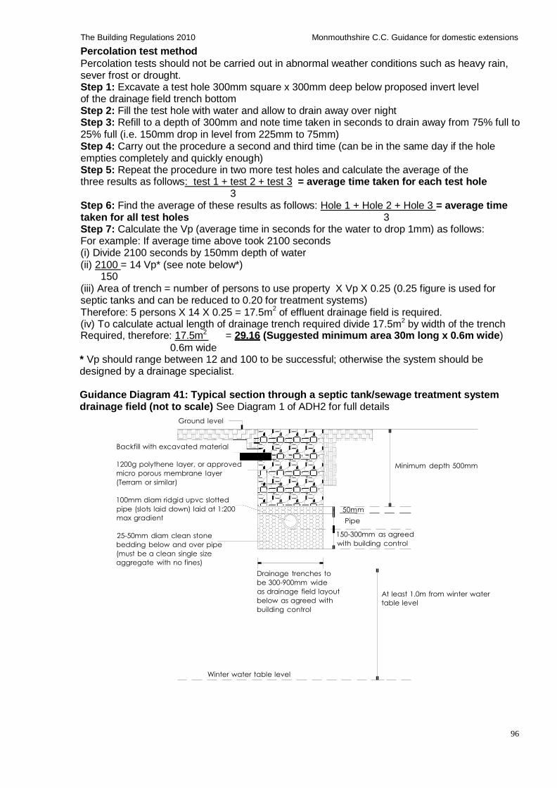
96
The Building Regulations 2010 Monmouthshire C.C. Guidance for domestic extensions
Percolation test method
Percolation tests should not be carried out in abnormal weather conditions such as heavy rain, sever frost or drought. Step 1: Excavate a test hole 300mm square x 300mm deep below proposed invert level of the drainage field trench bottom Step 2: Fill the test hole with water and allow to drain away over night Step 3: Refill to a depth of 300mm and note time taken in seconds to drain away from 75% full to 25% full (i.e. 150mm drop in level from 225mm to 75mm) Step 4: Carry out the procedure a second and third time (can be in the same day if the hole empties completely and quickly enough) Step 5: Repeat the procedure in two more test holes and calculate the average of the three results as follows: test 1 + test 2 + test 3 = average time taken for each test hole
3 Step 6: Find the average of these results as follows: Hole 1 + Hole 2 + Hole 3 = average time taken for all test holes 3 Step 7: Calculate the Vp (average time in seconds for the water to drop 1mm) as follows: For example: If average time above took 2100 seconds (i) Divide 2100 seconds by 150mm depth of water (ii) 2100 = 14 Vp* (see note below*)
150 (iii) Area of trench = number of persons to use property X Vp X 0.25 (0.25 figure is used for septic tanks and can be reduced to 0.20 for treatment systems) Therefore: 5 persons X 14 X 0.25 = 17.5m
2 of effluent drainage field is required.
(iv) To calculate actual length of drainage trench required divide 17.5m2 by width of the trench Required, therefore: 17.5m2 = 29.16 (Suggested minimum area 30m long x 0.6m wide)
0.6m wide * Vp should range between 12 and 100 to be successful; otherwise the system should be designed by a drainage specialist.
Guidance Diagram 41: Typical section through a septic tank/sewage treatment system drainage field (not to scale) See Diagram 1 of ADH2 for full details
Ground level
Backfill with excavated material
1200g polythene layer, or approved
micro porous membrane layer
(Terram or similar)
Minimum depth 500mm
100mm diam ridgid upvc slotted
pipe (slots laid down) laid at 1:200
max gradient
25-50mm diam clean stone
bedding below and over pipe
(must be a clean single size
aggregate with no fines)
50mm
Pipe
150-300mm as agreed
with building control
Drainage trenches to
be 300-900mm wide
as drainage field layout
below as agreed with
building control
At least 1.0m from winter water
table level
Winter water table level
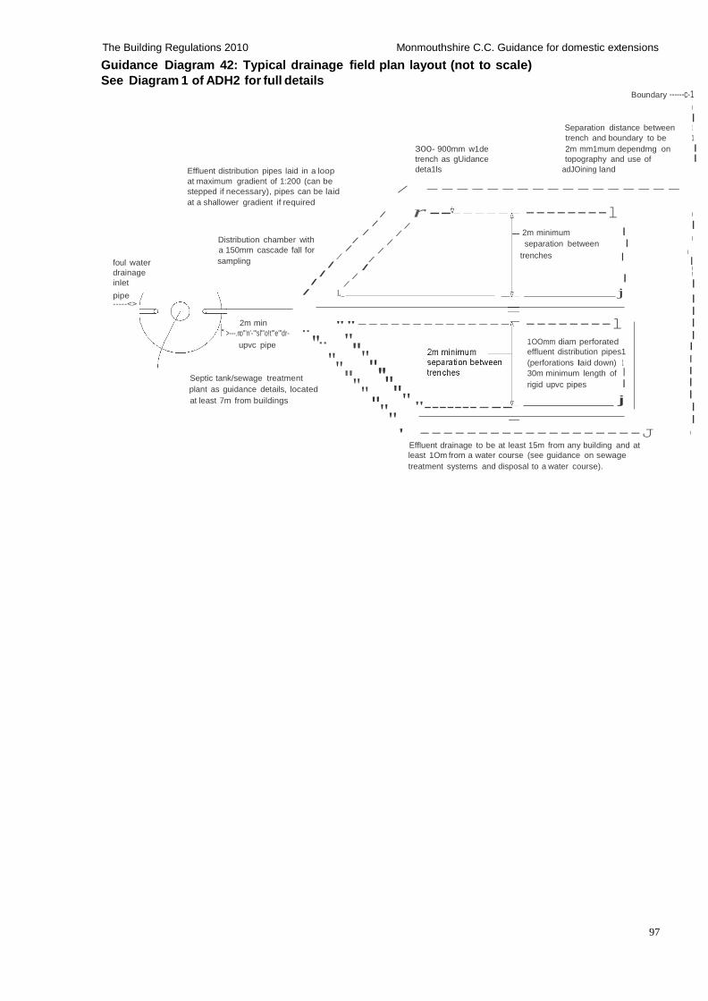
97
The Building Regulations 2010 Monmouthshire C.C. Guidance for domestic extensions
Guidance Diagram 42: Typical drainage field plan layout (not to scale)
See Diagram 1 of ADH2 for full details
Boundary ------c-1
I
I Separation distance between 1
trench and boundary to be 1
Effluent distribution pipes laid in a loop
at maximum gradient of 1:200 (can be
stepped if necessary), pipes can be laid
at a shallower gradient if required
300- 900mm w1de 2m mm1mum dependmg on I trench as gUidance topography and use of I deta1ls adJOining land
/ -----------------
/ r - / /
--------l I
I
foul water
drainage
inlet
/ / Distribution chamber with / / a 150mm cascade fall for / /
sampling / /
/ / / /
/
2m minimum I separation between I
I
trenches I I
I
I I
I
pipe -----<>
L_ _ j I I
2m min
>---.no"'n'-"'sl"'o!t"'e"'dr- "
upvc pipe "
""--------------
""
--------l I I
1OOmm diam perforated effluent distribution pipes1
Septic tank/sewage treatment
plant as guidance details, located
at least 7m from buildings
"" ""
""" """
(perforations Iaid down) 1 I 30m minimum length of I I rigid upvc pipes I I
j I
""" "------- --- I
I ' -------------------J I
Effluent drainage to be at least 15m from any building and at
least 1Om from a water course (see guidance on sewage
treatment systems and disposal to a water course).
98
The Building Regulations 2010 Monmouthshire C.C. Guidance for domestic extensions
Cesspools Cesspools are sealed watertight tanks used for the containment of domestic sewage and must be emptied regularly by a licensed contractor. Cesspools are used in locations without main drainage in locations acceptable to the Environment Agency, where the discharge of treated effluent is not permissible due to unsuitable ground conditions, or where infrequent use or seasonal use would prevent the functioning of a septic tank or sewage treatment system.
Proprietary factory made cesspools to be designed and constructed to BS EN 12566-1 and installed in compliance with manufacturer’s details, or
Non proprietary cesspool can be constructed in situ to a drainage specialist’s design and approved by Building Control before the works commence on site. Cesspools to be watertight to prevent leakage of the contents and ingress of sub soil water, Typically the tank consists of one chamber constructed using 150mm minimum thick reinforced concrete base designed by a suitably qualified specialist suitable for storing aggressive effluents, 215mm thick engineering quality brickwork walls (or dense concrete bricks), bond to be agreed with building control, mortar mix 1:3 cement/sand ratio with water proof render or suitable proprietary tanking system applied to both sides and designed heavy concrete roof structure.
Cesspools to be ventilated and fitted with durable lockable lids or covers for emptying and cleaning, and the inlet side of tank should be fitted with a lockable access for inspection. No other openings are permitted. A high level alarm should be fitted for monitoring the cesspool for optimum usage.
Cesspools to be sited:
At least 7m from any habitable part of any building, preferably down slopes and lower than any existing building and
Within 30m of a vehicle access suitable for emptying and cleaning the effluent, and the
contents should not be taken through a dwelling or place of work and must not be a hazard to the building occupants.
Cesspools should have a minimum capacity of 18,000 litres (18.0m3) for up to 2 users and increased by 6800 litres (6.8m3) for each additional user.
A notice plate must be fixed within the building describing the necessary maintenance and the following is an example of such wording:
'The foul drainage system from this property is served by a cesspool'
'The system should be emptied approximately every (insert frequency) by a licensed contractor and inspected fortnightly for overflow'
'The owner is legally responsible to ensure that the system does not cause pollution, a health hazard or a nuisance'
Consultations are to be carried out with Building Control and The Environment Agency before any works commence on site. Cesspools normally do not need registration with the Environment Agency as they are sealed systems with no discharge to the environment. For more information contact the Environment Agency at: www.environment-agency.gov.uk
99
The Building Regulations 2010 Monmouthshire C.C. Guidance for domestic extensions
H3: Rainwater drainage and harvesting
Rainwater gutters and down pipes
Rainwater gutters and down pipe sizes and number to be suitable for roof area to be drained in compliance with the guidance table below, and fixed in compliance with manufacturer's details. See H3 of ADH for further information
Guidance Table 48: Gutter sizes and pipe outlet sizes for drainage of roof areas
See Table 2 of ADH3 for full details
Maximum effective roof area m2 Gutter sizes (mm
diam) Outlet sizes (mm diam)
18.0 37.0 53.0 65.0 103.0
75 100 115 125 150
50 63 63 75 89
Note: The sizes above refer to half round gutters and round rain water pipes
Rainwater/ grey water harvesting storage tanks and systems
Rainwater harvesting system to be designed, installed, and commissioned by a specialist to supply rainwater to sanitary appliances. Below drainage pipe work is to be carried out in accordance with the foul water pipe guidance details above. Overflow from the rain water storage tank is to discharge to a designed soakaway system constructed at least 5m from any building.
Grey water (consisting of recycled bath, shower and basin waste water) systems designed for use within the building to be designed, manufactured, installed and commissioned by a suitably qualified and experienced specialist. Grey water to be treated prior to use in toilets etc by an approved method and overflow to discharge to the foul water drainage system.
Grey water and rainwater tanks and systems should:
Prevent leakage of the contents, ingress of subsoil water and should be ventilated
Have an anti backflow device on any overflow connected to a drain or sewer Have a corrosion proof locked access cover for emptying and cleaning
Supply pipes from the grey water or rain water collector tanks to the dwelling must be clearly marked as either ‘GREY WATER’ or ‘RAIN WATER’.
Guidance should be followed in par 1.69-1.72 of App Doc H2, App Doc G of the Building Regulations and the Water Regulations Advisory Scheme Leaflet No: 09-02-04, and BS 8515:2009.
Surface water drainage around the building Paths and paved areas around the building to have a non slip finish and provided with a surface cross fall of 1:40 – 1:60 to dispose of rain/surface water and a reverse gradient of at least 500mm away from walls of building (unless the paved/path area is a proprietary system designed to be porous and installed in accordance with manufacturer's details). Surface water to be disposed of by an adequately sized and roddable drainage system via soakaways, or other approved means.
Rain/surface water disposal
Rain/surface water to be piped away from buildings as detailed in guidance above and discharged in to new or existing surface water soakaway, storm water or combined storm/foul water drainage facilities using existing or new inspection chamber connection as shown on plans/ specification, or as agreed with building control on site. New connections to existing storm or combined storm/foul water systems may require consent from the relevant Water Authority before works commence on site. Rain/surface water should only connect into a combined system with the consent of the relevant Water Authority, and only into a foul system under exceptional circumstances and subject to written approval from the Water Authority.
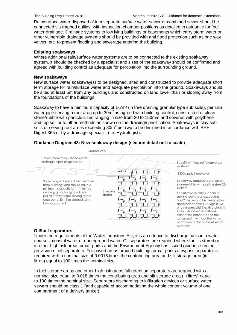
100
The Building Regulations 2010 Monmouthshire C.C. Guidance for domestic extensions
Rain/surface water disposed of in a separate surface water sewer or combined sewer should be connected via trapped gullies, with inspection chamber positions as detailed in guidance for foul water drainage. Drainage systems to low lying buildings or basements which carry storm water or other vulnerable drainage systems should be provided with anti flood protection such as one way valves, etc, to prevent flooding and sewerage entering the building.
Existing soakaways Where additional rain/surface water systems are to be connected to the existing soakaway system, it should be checked by a specialist and sizes of the soakaway should be confirmed and agreed with building control as adequate for percolation into the surrounding ground.
New soakaways New surface water soakaway(s) to be designed, sited and constructed to provide adequate short term storage for rain/surface water and adequate percolation into the ground. Soakaways should be sited at least 5m from any buildings and constructed on land lower than or sloping away from the foundations of the buildings.
Soakaway to have a minimum capacity of 1-2m³ (in free draining granular type sub soils), per rain
water pipe serving a roof area up to 30m2 as agreed with building control, constructed of clean stone/rubble with particle sizes ranging in size from 20 to 150mm and covered with polythene and top soil or to other methods as shown on the drawing/specification. Soakaways in clay sub soils or serving roof areas exceeding 30m2 per rwp to be designed in accordance with BRE Digest 365 or by a drainage specialist (i.e. Hydrologist).
Guidance Diagram 43: New soakaway design (section detail not to scale)
Ground level
100mm diam rain/surface water
drainage pipes as guidance Backfill with top soil/excavated
material
1200g polythene layer
Soakaway to be sited 5m minimum
from buildings and should have a
minimum capacity of 1m³ (in free
draining granular type sub soils),
per rain water pipe serving a roof
area up to 30m2 as agreed with
building control
Oil/fuel separators
Effective depth
Soakaway constructed of clean
stone/rubble with particle sizes 20- 150mm
Soakaways in clay sub soils or
serving roof areas exceeding
30m2 per rwp to be designed in
accordance with BRE Digest 365
or by a specialist (i.e. Hydrologist).
Rain/surface water systems
cannot be connected to foul
water drains without the written
permission of the relevant Water
Authority.
Under the requirements of the Water Industries Act, it is an offence to discharge fuels into water courses, coastal water or underground water. Oil separators are required where fuel is stored or in other high risk areas or car parks and the Environment Agency has issued guidance on the provision of oil separators. For paved areas around buildings or car parks a bypass separator is required with a nominal size of 0.0018 times the contributing area and silt storage area (in litres) equal to 100 times the nominal size.
In fuel storage areas and other high risk areas full retention separators are required with a nominal size equal to 0.018 times the contributing area and silt storage area (in litres) equal to 100 times the nominal size. Separators discharging to infiltration devices or surface water sewers should be class 1 (and capable of accommodating the whole content volume of one compartment of a delivery tanker)
101
The Building Regulations 2010 Monmouthshire C.C. Guidance for domestic extensions
Proprietary oil separators should be factory made, water proof, designed and constructed to the requirements of the Environment Agency, licensing authorities requirements (where the Petroleum Act applies), prEN858 and BBA certification or other approved accreditation). Separators must be installed and maintained in compliance with the manufacturer's details and inlet arrangements should not be direct to the water surface, adequate ventilation must be provided. The separator must be cleaned out and emptied regularly by a licensed contractor. See Appendix H3 -A of ADH3 for further information
H4: Building over or close to and connections to public sewers
Building over or close to a Public Sewer The Water Authority (WA) being the sewerage undertaker is responsible for maintaining public sewers and the owner/developer of a building being constructed, extended or underpinned within 3m of a public sewer as indicated on the relevant WA sewer maps are required to consult with the WA to ensure: (i) No damage occurs to the sewer. The extra weight of building being constructed, extended or underpinned a new building above a sewer could cause the sewer to collapse, resulting in structural damage to the new building, interrupted drainage from other properties and wastewater flooding. In these instances the sewer will need to be repaired quickly and this may involve taking down the building. (ii) Suitable access is available to carry out any maintenance, repair or replacement works to the public sewer. (iii) Consent is obtained and an agreement is entered into to build close to or over the public sewer before works commence on site
Locating a public sewer Copies of the sewer record maps are held by the WA and Local Authority for the location of public sewers, and checks should be carried out at an early stage to ensure that the proposed works do not effect a public sewer.
Options
If you find that your plans could affect a public sewer, you should consult the relevant WA and discuss with them the following options;
• Avoiding the sewer through modifications of plans so that the building is at least 3 metres away from the sewer. This is often the easiest and cheapest option.
• Diverting the sewer. If the plans cannot be modified, the WA will usually require the sewer to be diverted. In most cases the diversion works is carried out at the property owners expense, normally by contractors approved by the WA.
The WA will not normally allowed construction directly over a manhole or pressurized pumping main.
The Build Over Process If the only option is to apply to build over a public sewer, the building owner should make an application to the WA who may allow to build over a sewer, subject to the sewer being in satisfactory condition and their written Agreement before works commence.
Typical procedure:
A Closed Circuit Television (CCTV) survey is carried out by WA before works commence to ascertain whether any repair work is required
Another survey is required when the building is completed, to check that the sewer has not been damaged.
In certain circumstances, if the building owner does not obtain the WA agreement, the WA
have the right to discontinue the works, and the take down the building erected over the public sewer.
102
The Building Regulations 2010 Monmouthshire C.C. Guidance for domestic extensions
Consultations should be carried out early on in the design process to avoid any abortive costs, delays or other problems.
The WA make a charge for applications. Private Sewer Transfer Regulations Since the implementation of the Private Sewer Transfer Regulations on 1st October 2011, all lateral drains and sewers, i.e. those serving two or more properties that connect to the public sewer network, will be adopted by the relevant Water Authority/sewerage provider and the above requirements for building over/ close to and/or making new connections to public sewers will apply. As these lateral drains and sewers may not yet show up on the sewer maps it is important that consultations with the WA are carried out at an early stage. Protection Protection of the sewer pipes and systems are to be carried out in compliance with the WA requirements.
Further information Is available from the relevant Water Authority or www.defra.gov.uk/environment/quality/water/sewage/sewers or www.water.org.uk/home/policy/private-sewer-transfer
Connections to public sewers Owners/developers of a building with new drainage connections or indirect drainage connections being made to a public sewer as indicated on the relevant Water Authorities sewer maps are required to consult with the WA and where necessary obtain consent before works commence on site.
H5: Separate systems of drainage The building owner/agent must carry out all necessary consultations with the relevant Water Authority before works commence on site. Rain/surface water systems cannot be connected to foul water drains without the written permission of the relevant Water Authority. See H5 of ADH for further information.
H6: Solid waste storage Only applies to new dwellings and conversion to create a new dwelling. See H6 of ADH and new dwellings in this guidance for further information
103
The Building Regulations 2010 Monmouthshire C.C. Guidance for domestic extensions
Part J: Combustion appliances and fuel storage systems Please refer fully to Approved Document J: Combustion appliances and fuel storage systems (2010 edition with further 2010 amendments);
Contents Space and hot water heat producing appliances in general
Guidance Table 49: Typical minimum design guide temperatures for rooms Solid fuel appliances up to 50kW rated output
Construction of open fire recessed and hearth Guidance Diagram 44: Non combustible hearth details for recessed open fire Construction of solid fuel masonry chimneys Guidance Diagram 45: Solid fuel masonry chimney construction Guidance Diagram 46: Lead flashing detail to solid fuel masonry chimney Guidance Diagram 47: Solid fuel chimney construction with bends Guidance Diagram 48: Minimum separation distances from combustible material in or near to a solid fuel chimney Free standing solid fuel stove and hearth Guidance Diagram 49: Non combustible hearth detail under free standing solid fuel stove Flue pipe connections to free standing stove and chimneys Construction of factory made insulated twin walled metal chimneys Guidance Diagram 50: Free standing stove and metal chimney detail through a building Guidance Diagram 51: Separation of twin walled insulated flue from combustible materials Guidance Table 50: Sizes of flues in chimneys Carbon monoxide alarms Air supply (ventilation) to solid fuel appliances Guidance Table 51: Air supply (permanent ventilation) to solid fuel appliances Construction of factory made flue block chimneys Configuration of flues serving open flue appliances Inspection and cleaning openings in chimneys and flues Interaction of mechanical extract vents and opened flue combustion appliances Chimney /flue heights Repair/relining of existing flues Notice plates for hearths and flues
Appliances other than solid fuel Gas heating appliances up to 70kw
Interaction of mechanical extract vents and opened flue gas combustion appliances Oil heating appliances up to 45kW
Interaction of mechanical extract vents and opened flue oil combustion appliances Fuel storage tanks
LPG tanks and cylinders up to 1.1 tonnes Oil tanks up to 3500 litres
Renewable energy/micro regeneration Installations Provision of information- commissioning certificates (testing)
Part J: Combustion appliances and fuel storage systems
Space and hot water heat producing appliances in general All space and hot water systems must be in accordance with BS 5449, BS 5410 and BS 8303, installed, commissioned, calibrated and certified by a suitably qualified person or installer registered with an appropriate competent persons scheme and details supplied to Building Control and the owner along with the operating manuals, etc before the building is completed/ occupied.
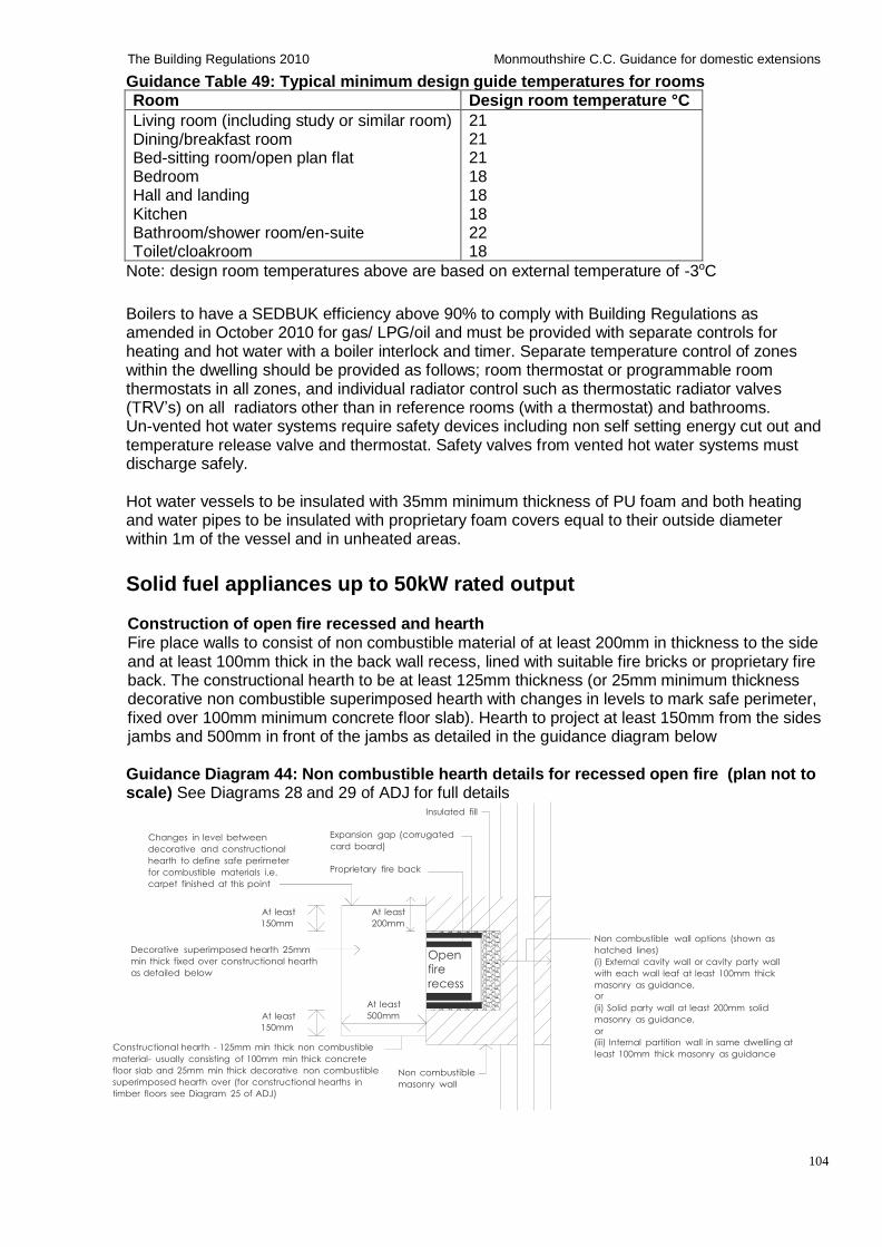
104
The Building Regulations 2010 Monmouthshire C.C. Guidance for domestic extensions
Guidance Table 49: Typical minimum design guide temperatures for rooms
Room Design room temperature °C
Living room (including study or similar room) Dining/breakfast room Bed-sitting room/open plan flat Bedroom Hall and landing Kitchen Bathroom/shower room/en-suite Toilet/cloakroom
21 21 21 18 18 18 22 18
Note: design room temperatures above are based on external temperature of -3oC
Boilers to have a SEDBUK efficiency above 90% to comply with Building Regulations as amended in October 2010 for gas/ LPG/oil and must be provided with separate controls for heating and hot water with a boiler interlock and timer. Separate temperature control of zones within the dwelling should be provided as follows; room thermostat or programmable room thermostats in all zones, and individual radiator control such as thermostatic radiator valves (TRV’s) on all radiators other than in reference rooms (with a thermostat) and bathrooms. Un-vented hot water systems require safety devices including non self setting energy cut out and temperature release valve and thermostat. Safety valves from vented hot water systems must discharge safely.
Hot water vessels to be insulated with 35mm minimum thickness of PU foam and both heating and water pipes to be insulated with proprietary foam covers equal to their outside diameter within 1m of the vessel and in unheated areas.
Solid fuel appliances up to 50kW rated output
Construction of open fire recessed and hearth Fire place walls to consist of non combustible material of at least 200mm in thickness to the side and at least 100mm thick in the back wall recess, lined with suitable fire bricks or proprietary fire back. The constructional hearth to be at least 125mm thickness (or 25mm minimum thickness decorative non combustible superimposed hearth with changes in levels to mark safe perimeter, fixed over 100mm minimum concrete floor slab). Hearth to project at least 150mm from the sides jambs and 500mm in front of the jambs as detailed in the guidance diagram below
Guidance Diagram 44: Non combustible hearth details for recessed open fire (plan not to scale) See Diagrams 28 and 29 of ADJ for full details
Insulated fill
Changes in level between
decorative and constructional
hearth to define safe perimeter
for combustible materials i.e.
carpet finished at this point
Expansion gap (corrugated
card board)
Proprietary fire back
At least
150mm
Decorative superimposed hearth 25mm
min thick fixed over constructional hearth
as detailed below
At least
150mm
At least
200mm
At least
500mm
Open fire
recess
Non combustible wall options (shown as
hatched lines)
(i) External cavity wall or cavity party wall
with each wall leaf at least 100mm thick
masonry as guidance,
or
(ii) Solid party wall at least 200mm solid
masonry as guidance,
or
Constructional hearth - 125mm min thick non combustible
material- usually consisting of 100mm min thick concrete
floor slab and 25mm min thick decorative non combustible
superimposed hearth over (for constructional hearths in
timber floors see Diagram 25 of ADJ)
Non combustible
masonry wall
(iii) Internal partition wall in same dwelling at
least 100mm thick masonry as guidance
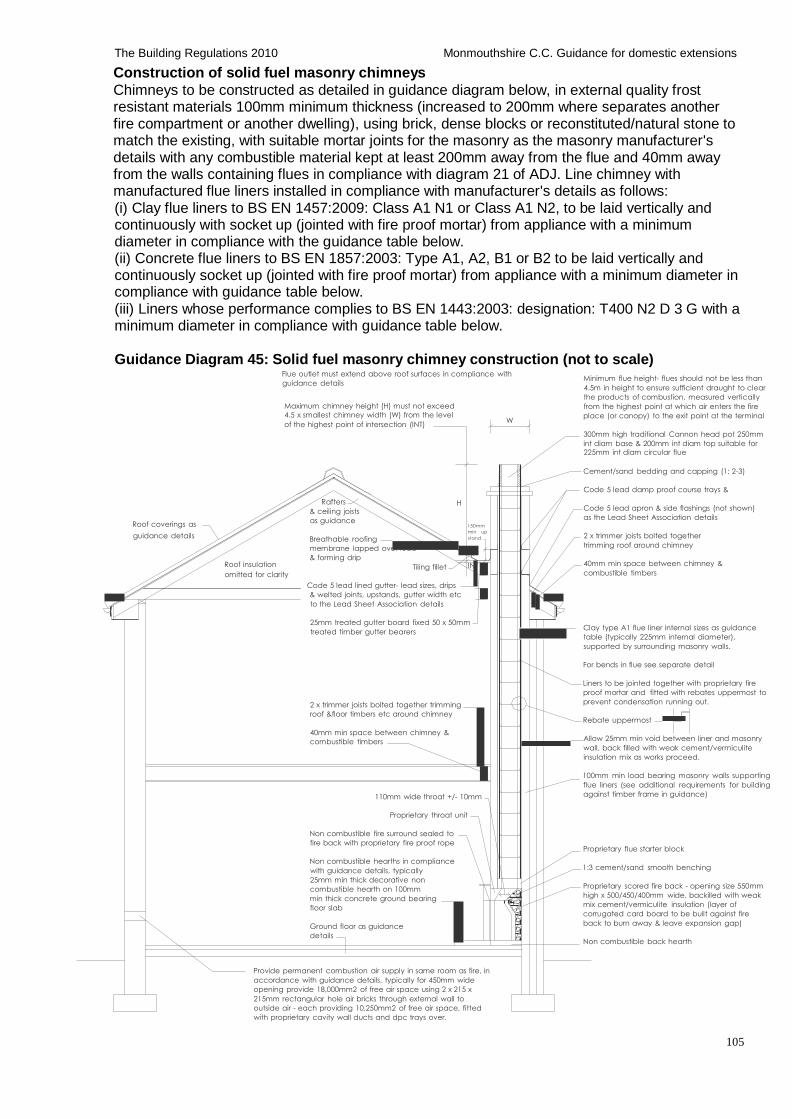
105
The Building Regulations 2010 Monmouthshire C.C. Guidance for domestic extensions
er
Construction of solid fuel masonry chimneys
Chimneys to be constructed as detailed in guidance diagram below, in external quality frost resistant materials 100mm minimum thickness (increased to 200mm where separates another fire compartment or another dwelling), using brick, dense blocks or reconstituted/natural stone to match the existing, with suitable mortar joints for the masonry as the masonry manufacturer's details with any combustible material kept at least 200mm away from the flue and 40mm away from the walls containing flues in compliance with diagram 21 of ADJ. Line chimney with manufactured flue liners installed in compliance with manufacturer's details as follows: (i) Clay flue liners to BS EN 1457:2009: Class A1 N1 or Class A1 N2, to be laid vertically and continuously with socket up (jointed with fire proof mortar) from appliance with a minimum diameter in compliance with the guidance table below. (ii) Concrete flue liners to BS EN 1857:2003: Type A1, A2, B1 or B2 to be laid vertically and continuously socket up (jointed with fire proof mortar) from appliance with a minimum diameter in compliance with guidance table below. (iii) Liners whose performance complies to BS EN 1443:2003: designation: T400 N2 D 3 G with a minimum diameter in compliance with guidance table below.
Guidance Diagram 45: Solid fuel masonry chimney construction (not to scale)
Flue outlet must extend above roof surfaces in compliance with
guidance details
Maximum chimney height (H) must not exceed
4.5 x smallest chimney width (W) from the level
Minimum flue height- flues should not be less than
4.5m in height to ensure sufficient draught to clear
the products of combustion, measured vertically
from the highest point at which air enters the fire
place (or canopy) to the exit point at the terminal
of the highest point of intersection (INT) W
300mm high traditional Cannon head pot 250mm
int diam base & 200mm int diam top suitable for 225mm int diam circular flue
Cement/sand bedding and capping (1: 2-3)
Roof coverings as
guidance details
Roof insulation
omitted for clarity
Rafters
& ceiling joists
as guidance
Breathable roofing
membrane lapped ov
& forming drip
Tiling fillet
H
150mm
min up
stand
INT
Code 5 lead damp proof course trays &
Code 5 lead apron & side flashings (not shown)
as the Lead Sheet Association details
2 x trimmer joists bolted together
trimming roof around chimney
40mm min space between chimney &
combustible timbers
Code 5 lead lined gutter- lead sizes, drips
& welted joints, upstands, gutter width etc
to the Lead Sheet Association details
25mm treated gutter board fixed 50 x 50mm
treated timber gutter bearers
2 x trimmer joists bolted together trimming
roof &floor timbers etc around chimney
40mm min space between chimney &
combustible timbers
110mm wide throat +/- 10mm
Proprietary throat unit
Non combustible fire surround sealed to
fire back with proprietary fire proof rope
Non combustible hearths in compliance
with guidance details, typically
25mm min thick decorative non
combustible hearth on 100mm
min thick concrete ground bearing
floor slab
Ground floor as guidance
details
Clay type A1 flue liner internal sizes as guidance
table (typically 225mm internal diameter),
supported by surrounding masonry walls.
For bends in flue see separate detail
Liners to be jointed together with proprietary fire
proof mortar and fitted with rebates uppermost to
prevent condensation running out.
Rebate uppermost
Allow 25mm min void between liner and masonry
wall, back filled with weak cement/vermiculite
insulation mix as works proceed.
100mm min load bearing masonry walls supporting
flue liners (see additional requirements for building
against timber frame in guidance)
Proprietary flue starter block
1:3 cement/sand smooth benching
Proprietary scored fire back - opening size 550mm
high x 500/450/400mm wide, backilled with weak
mix cement/vermiculite insulation (layer of
corrugated card board to be built against fire
back to burn away & leave expansion gap)
Non combustible back hearth
Provide permanent combustion air supply in same room as fire, in
accordance with guidance details, typically for 450mm wide
opening provide 18,000mm2 of free air space using 2 x 215 x
215mm rectangular hole air bricks through external wall to
outside air - each providing 10,250mm2 of free air space, fitted
with proprietary cavity wall ducts and dpc trays over.
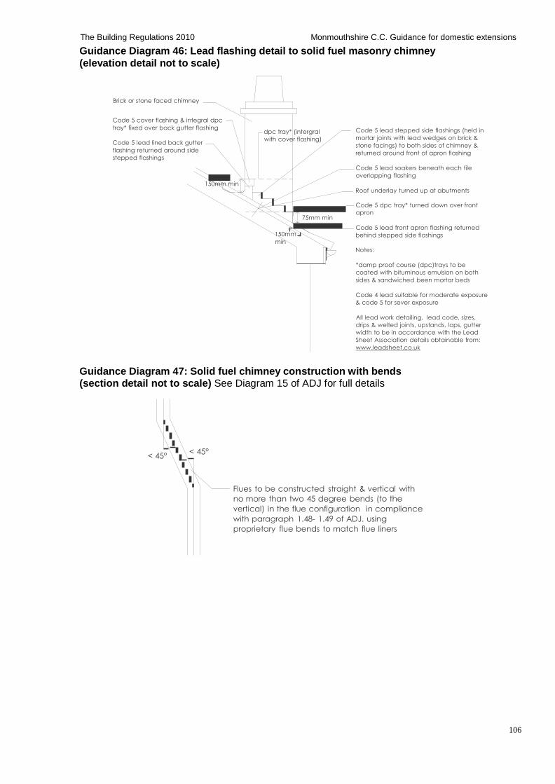
106
The Building Regulations 2010 Monmouthshire C.C. Guidance for domestic extensions
Guidance Diagram 46: Lead flashing detail to solid fuel masonry chimney
(elevation detail not to scale)
Brick or stone faced chimney
Code 5 cover flashing & integral dpc
tray* fixed over back gutter flashing
Code 5 lead lined back gutter
flashing returned around side
stepped flashings
150mm min
dpc tray* (intergral
with cover flashing)
Code 5 lead stepped side flashings (held in
mortar joints with lead wedges on brick &
stone facings) to both sides of chimney &
returned around front of apron flashing
Code 5 lead soakers beneath each tile
overlapping flashing
Roof underlay turned up at abutments
150mm
min
75mm min
Code 5 dpc tray* turned down over front
apron
Code 5 lead front apron flashing returned
behind stepped side flashings
Notes:
*damp proof course (dpc)trays to be
coated with bituminous emulsion on both
sides & sandwiched been mortar beds
Code 4 lead suitable for moderate exposure
& code 5 for sever exposure
All lead work detailing, lead code, sizes,
drips & welted joints, upstands, laps, gutter
width to be in accordance with the Lead
Sheet Association details obtainable from:
www.leadsheet.co.uk
Guidance Diagram 47: Solid fuel chimney construction with bends (section detail not to scale) See Diagram 15 of ADJ for full details
< 45° < 45°
Flues to be constructed straight & vertical with
no more than two 45 degree bends (to the
vertical) in the flue configuration in compliance
with paragraph 1.48- 1.49 of ADJ. using
proprietary flue bends to match flue liners
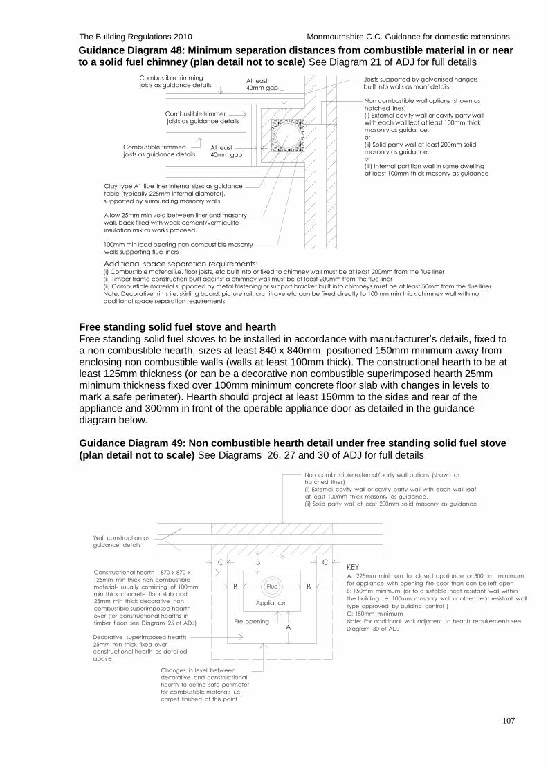
107
The Building Regulations 2010 Monmouthshire C.C. Guidance for domestic extensions
Guidance Diagram 48: Minimum separation distances from combustible material in or near to a solid fuel chimney (plan detail not to scale) See Diagram 21 of ADJ for full details
Combustible trimming
joists as guidance details
Combustible trimmer
joists as guidance details
At least 40mm gap
Joists supported by galvanised hangers
built into walls as manf details Non combustible wall options (shown as
hatched lines)
(i) External cavity wall or cavity party wall
with each wall leaf at least 100mm thick
masonry as guidance,
or
Combustible trimmed
joists as guidance details At least 40mm gap
(ii) Solid party wall at least 200mm solid
masonry as guidance, or
(iii) Internal partition wall in same dwelling
at least 100mm thick masonry as guidance
Clay type A1 flue liner internal sizes as guidance
table (typically 225mm internal diameter),
supported by surrounding masonry walls.
Allow 25mm min void between liner and masonry
wall, back filled with weak cement/vermiculite
insulation mix as works proceed.
100mm min load bearing non combustible masonry
walls supporting flue liners
Additional space separation requirements: (i) Combustible material i.e. floor joists, etc built into or fixed to chimney wall must be at least 200mm from the flue liner
(ii) Timber frame construction built against a chimney wall must be at least 200mm from the flue liner
(ii) Combustible material supported by metal fastening or support bracket built into chimneys must be at least 50mm from the flue liner
Note: Decorative trims i.e. skirting board, picture rail, architrave etc can be fixed directly to 100mm min thick chimney wall with no
additional space separation requirements
Free standing solid fuel stove and hearth
Free standing solid fuel stoves to be installed in accordance with manufacturer’s details, fixed to a non combustible hearth, sizes at least 840 x 840mm, positioned 150mm minimum away from enclosing non combustible walls (walls at least 100mm thick). The constructional hearth to be at least 125mm thickness (or can be a decorative non combustible superimposed hearth 25mm minimum thickness fixed over 100mm minimum concrete floor slab with changes in levels to mark a safe perimeter). Hearth should project at least 150mm to the sides and rear of the appliance and 300mm in front of the operable appliance door as detailed in the guidance diagram below.
Guidance Diagram 49: Non combustible hearth detail under free standing solid fuel stove
(plan detail not to scale) See Diagrams 26, 27 and 30 of ADJ for full details
Non combustible external/party wall options (shown as
hatched lines)
(i) External cavity wall or cavity party wall with each wall leaf
at least 100mm thick masonry as guidance.
(ii) Solid party wall at least 200mm solid masonry as guidance
Wall construction as
guidance details
Constructional hearth - 870 x 870 x
125mm min thick non combustible
material- usually consisting of 100mm
min thick concrete floor slab and
25mm min thick decorative non
combustible superimposed hearth
over (for constructional hearths in
timber floors see Diagram 25 of ADJ)
Decorative superimposed hearth
25mm min thick fixed over
constructional hearth as detailed
above
C B C
B Flue B
Appliance
Fire opening
A
KEY A: 225mm minimum for closed appliance or 300mm minimum
for appliance with opening fire door than can be left open
B: 150mm minimum (or to a suitable heat resistant wall within
the building i.e. 100mm masonry wall or other heat resistant wall
type approved by building control )
C: 150mm minimum
Note: For additional wall adjacent to hearth requirements see
Diagram 30 of ADJ
Changes in level between
decorative and constructional
hearth to define safe perimeter
for combustible materials i.e.
carpet finished at this point
108
The Building Regulations 2010 Monmouthshire C.C. Guidance for domestic extensions
Flue pipe connections to free standing stove and chimneys
Single flue pipes connecting the appliance to a chimney should not extend beyond the room in which the appliance is located, and should not pass through any roof space, partition, internal wall or floor (unless it connects to the chimney at that point). The maximum recommended length is 1-1.5m to prevent heat transfer and improve flue efficiency. Minimum flue length 0.6m.
Single flue pipes should be guarded if they could be at risk of damage, or if the burn hazard is not immediately apparent to people. Single flue pipes must be located to avoid igniting combustible materials and must be at least 3 times its internal diameter from any combustible materials (3 x 150mm = 450mm); or
The combustible material can be heat shielded, the flue must be at least or 1.5 times its diameter from the heat shield. The heat shield (typically 12mm thick proprietary fire resistant board) must extend at least 1.5 times the flues internal diameter to each side of the flue and there must be an air gap of at least 12mm (formed with strips of fire board) between the shield material and the combustible material; or
The connecting flue pipe is factory made in compliance with T 400 N2 D3 G according to BS EN 1856-2:2004, and installed to BS EN 15827-1
Construction of factory made insulated twin walled metal chimneys Construction of factory made metal chimneys are to be carried out in compliance with paragraphs 1.42 – 1.46 of ADJ, and appliance manufacturer’s details. The separation of combustible materials from a factory- made twin walled metal chimney is to be carried out in compliance with Diagram 13 of ADJ. Where a metal chimney passes through a cupboard, storage space or roof space it must be fully separated with at least 50mm from combustible materials with a non combustible steel mesh guard. Factory made metal chimneys concealed in the building are to be accessible for inspection in compliance with paragraph 1.47 and diagrams 13 and 14 of ADJ. Chimneys passing through combustible floors and roofs should be fitted with proprietary fire stop shields. Chimneys passing through fire compartment walls or floors-contact building control for further advice.
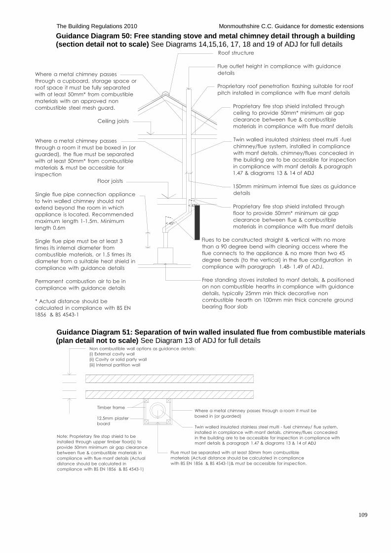
109
The Building Regulations 2010 Monmouthshire C.C. Guidance for domestic extensions
Guidance Diagram 50: Free standing stove and metal chimney detail through a building (section detail not to scale) See Diagrams 14,15,16, 17, 18 and 19 of ADJ for full details
Roof structure
Where a metal chimney passes
through a cupboard, storage space or
roof space it must be fully separated
with at least 50mm* from combustible
materials with an approved non
combustible steel mesh guard.
Ceiling joists
Flue outlet height in compliance with guidance
details
Proprietary roof penetration flashing suitable for roof
pitch installed in compliance with flue manf details
Proprietary fire stop shield installed through
ceiling to provide 50mm* minimum air gap
clearance between flue & combustible
materials in compliance with flue manf details
Where a metal chimney passes
through a room it must be boxed in (or
guarded), the flue must be separated
with at least 50mm* from combustible
materials & must be accessible for
inspection
Floor joists
Single flue pipe connection appliance
to twin walled chimney should not
extend beyond the room in which
appliance is located. Recommended
maximum length 1-1.5m. Minimum
length 0.6m
Single flue pipe must be at least 3
times its internal diameter from
combustible materials, or 1.5 times its
diameter from a suitable heat shield in
compliance with guidance details
Permanent combustion air to be in
compliance with guidance details
* Actual distance should be
calculated in compliance with BS EN
1856 & BS 4543-1
< 45°
< 45°
Twin walled insulated stainless steel multi -fuel
chimney/flue system, installed in compliance
with manf details. chimney/flues concealed in
the building are to be accessible for inspection
in compliance with manf details & paragraph
1.47 & diagrams 13 & 14 of ADJ
150mm minimum internal flue sizes as guidance
details
Proprietary fire stop shield installed through
floor to provide 50mm* minimum air gap
clearance between flue & combustible
materials in compliance with flue manf details
Flues to be constructed straight & vertical with no more
than a 90 degree bend with cleaning access where the
flue connects to the appliance & no more than two 45
degree bends (to the vertical) in the flue configuration in
compliance with paragraph 1.48- 1.49 of ADJ.
Free standing stoves installed to manf details, & positioned
on non combustible hearths in compliance with guidance
details, typically 25mm min thick decorative non
combustible hearth on 100mm min thick concrete ground
bearing floor slab
Guidance Diagram 51: Separation of twin walled insulated flue from combustible materials (plan detail not to scale) See Diagram 13 of ADJ for full details
Non combustible wall options as guidance details:
(i) External cavity wall
(ii) Cavity or solid party wall
(iii) Internal partition wall
Timber frame
12.5mm plaster
board
Note: Proprietary fire stop shield to be
installed through upper timber floor(s) to
provide 50mm minimum air gap clearance
between flue & combustible materials in
compliance with flue manf details (Actual
distance should be calculated in
compliance with BS EN 1856 & BS 4543-1)
Where a metal chimney passes through a room it must be
boxed in (or guarded)
Twin walled insulated stainless steel multi - fuel chimney/ flue system,
installed in compliance with manf details. chimney/flues concealed
in the building are to be accessible for inspection in compliance with
manf details & paragraph 1.47 & diagrams 13 & 14 of ADJ
Flue must be separated with at least 50mm from combustible
materials (Actual distance should be calculated in compliance
with BS EN 1856 & BS 4543-1)& must be accessible for inspection.
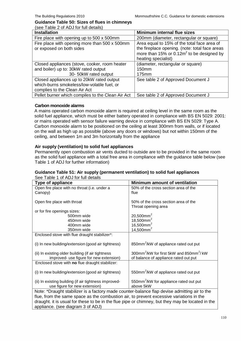
110
The Building Regulations 2010 Monmouthshire C.C. Guidance for domestic extensions
Guidance Table 50: Sizes of flues in chimneys
(see Table 2 of ADJ for full details) Installation Minimum internal flue sizes
Fire place with opening up to 500 x 500mm 200mm (diameter, rectangular or square)
Fire place with opening more than 500 x 500mm or exposed on both sides
Area equal to 15% of the total face area of the fireplace opening. (note: total face areas
more than 15% or 0.12m2 to be designed by heating specialist)
Closed appliances (stove, cooker, room heater and boiler) up to: 30kW rated output
30- 50kW rated output
(diameter, rectangular or square) 150mm 175mm
Closed appliances up to 20kW rated output which-burns smokeless/low-volatile fuel, or complies to the Clean Air Act
See table 2 of Approved Document J
Pellet burner which compiles to the Clean Air Act See table 2 of Approved Document J
Carbon monoxide alarms
A mains operated carbon monoxide alarm is required at ceiling level in the same room as the solid fuel appliance, which must be either battery operated in compliance with BS EN 5029: 2001: or mains operated with sensor failure warning device in compliance with BS EN 5029: Type A. Carbon monoxide alarm to be positioned on the ceiling at least 300mm from walls, or if located on the wall as high up as possible (above any doors or windows) but not within 150mm of the ceiling, and between 1m and 3m horizontally from the appliance
Air supply (ventilation) to solid fuel appliances
Permanently open combustion air vents ducted to outside are to be provided in the same room as the solid fuel appliance with a total free area in compliance with the guidance table below (see Table 1 of ADJ for further information)
Guidance Table 51: Air supply (permanent ventilation) to solid fuel appliances
See Table 1 of ADJ for full details Type of appliance Minimum amount of ventilation Open fire place with no throat (i.e. under a Canopy)
Open fire place with throat
or for fire openings sizes: 500mm wide 450mm wide 400mm wide 350mm wide
50% of the cross section area of the flue
50% of the cross section area of the Throat opening area
20,500mm2
18,500mm2
16,500mm2
14,500mm2
Enclosed stove with flue draught stabilizer*:
(i) In new building/extension (good air tightness)
(ii) In existing older building (if air tightness improved- use figure for new extension)
850mm2/kW of appliance rated out put
300mm2/kW for first 5kW and 850mm
2/ kW
of balance of appliance rated out put
Enclosed stove with no flue draught stabilizer:
(i) In new building/extension (good air tightness)
(ii) In existing building (if air tightness improved- use figure for new extension)
550mm2/kW of appliance rated out put
550mm2/kW for appliance rated out put
above 5kW
Note: *Draught stabilizer is a factory made counter-balance flap devise admitting air to the flue, from the same space as the combustion air, to prevent excessive variations in the draught. it is usual for these to be in the flue pipe or chimney, but they may be located in the appliance. (see diagram 3 of ADJ)
111
The Building Regulations 2010 Monmouthshire C.C. Guidance for domestic extensions
Construction of factory made flue block chimneys
Construction of factory made flue block chimneys are to be carried out in compliance with paragraphs 1.29 – 1.30 of ADJ, and appliance manufacturer’s details.
Configuration of flues serving open flue appliances Flues to be constructed straight and vertical with no more than a 90 degree bend with cleaning access where the flue connects to the appliance and no more than two 45 degree bends (to the vertical) in the flue configuration in compliance with paragraph 1.48- 1.49 of ADJ.
Inspection and cleaning openings in chimneys and flues Where a chimney/flue cannot be cleaned through the appliance, an air tight accessible inspection and cleaning opening should be fitted using proprietary factory made components compatible with the flue system, fitted and located to allow sweeping of the flue in compliance with appliance manufacturer's details.
Interaction of mechanical extract vents and opened flue combustion appliances Where a kitchen etc contains an opened flue solid fuel appliance and a mechanical extract vent, the appliance should be tested and certificated by a suitable qualified and registered HETAS engineer that the combustion appliance operates safely whether or not the fans are running. Alternatively, the ventilation from the passive stack effect of an open flue appliance may negate the need for a mechanical extract fan to be fitted in the same room subject to approval by building control.
Chimney /flue heights
Chimney height not to exceed 4.5 times its narrowest thickness above highest point of
intersection (density of masonry to be greater than 1500kg/m3). Chimney/terminal to discharge at a minimum height in compliance with Diagram 17 of ADJ as follows:
1.0m above flat roofs
1.0m above opening windows or roof lights in the roof surface
0.6m above the ridge Outside of a zone measured 2.3m horizontally from the roof slope 0.6m above an adjoining or adjacent building that is within 2.3m measured horizontally
(whether or not beyond the boundary) Please refer to Diagram 18 of ADJ for flue positions on easily ignited roofs (i.e. thatch)
Repair/relining of existing flues Repair /relining of existing flues to be carried out by a suitably qualified and experienced specialist. Re-use of existing flues to be inspected, tested and certified by a suitably qualified and experienced specialist prior to use as suitable for solid fuel appliances.
Relining of existing flues to be carried out in compliance with BS EN 1443:2003: designation: T400 N2 D 3 G with minimum diameters in compliance with guidance table above using lining systems suitable for solid fuel appliances as follows:
(i) Factory made flue lining systems in compliance with BSEN1856-1:2003 or BSEN1856-2:2004 (ii) Cast in-situ flue lining system in compliance with BSEN1857:2003+A1:2008
Notice plates for hearths and flues Notice plates for hearths and flues must be permanently displayed next to the flue (or electricity consumer unit or water stop tap) detailing the property address; location of installation (room); type of installation the flue is suitable for; size and construction of flue, if suitable for condensing appliance, installation date, and any other information (optional).
112
The Building Regulations 2010 Monmouthshire C.C. Guidance for domestic extensions
Appliances other than solid fuel
Gas heating appliances up to 70kw Gas burning appliances up to 70kW are out of the scope of this guidance and to be installed, commissioned and tested in compliance with Section 3 of ADJ, and BS 5440, BS 5546, BS 5864, BS 5871, BS 6172, BS 6173, BS 6798, and the Gas Safety (installation and use) Regulations. All works to be to be carried out by an installer registered with Gas Safe. Copy of commissioning certificates are to be issued to Building Control on completion of the works.
Interaction of mechanical extract vents and opened flue gas combustion appliances Where a kitchen etc contains an opened flue gas appliance and a mechanical extract vent, the rate of the
extract fan should not exceed 20l/s (73m3/hour) and the appliance should be tested and certificated by a suitable qualified and registered gas engineer that the combustion appliance operates safely whether or not the fans are running.
Oil heating appliances up to 45kW Oil burning appliances up to 45kW are out of the scope of this guidance and to be installed, commissioned and tested in compliance with Section 4 of ADJ and BS 5410, BS 799. All works should be carried out by an installer registered with OFTEC. Copies of commissioning certificates are to be issued to Building Control on completion of the works.
Interaction of mechanical extract vents and opened flue oil combustion appliances Where a kitchen etc contains an opened flue oil appliance and a mechanical extract vent, the rate of the extract fan should not exceed 40 l/s for an appliance with a pressure jet burner and 20l/s for an appliance with a vaporising burner and the appliance should be tested and certificated by a suitable qualified and registered OFTEC engineer that the combustion appliance operates safely whether or not the fans are running.
Fuel storage tanks LPG tanks and cylinders up to 1.1 tonnes LPG tanks up to 0.25 tonne capacity s to be positioned in the open air at least 2.5m from buildings or boundaries and 1.1 tonne tanks positioned 3m from buildings or boundaries . Cylinders to be positioned in the open air on a minimum 50mm thick concrete base, securely chained to the wall and positioned at least 250mm below and 1m from any openings horizontally into the building such as windows, combustion vents or flue terminals and 2m from un-trapped drains or cellar entrances. See Section Diagram 43 and 44 and Section 5 of ADJ for full details
Oil tanks up to 3500 litres
Oil tanks up to 3500 litres to be positioned in the open air on a concrete base with a minimum thickness of 50mm extending a minimum of 300mm beyond the tank base and be positioned a minimum of 1.8m from buildings or flues and 760mm from boundaries. They should also be provided with a proprietary fire resistant pipe and valve system. Where there is a risk of pollution to water courses, open drains including inspection chambers with loose covers, the tank should be either internally bunded or be provided with an impervious masonry bund equal to capacity of 110% of its volume. Where any of the above requirements cannot be met- please contact Building Control for further guidance. See Section 5 of ADJ for full details
113
The Building Regulations 2010 Monmouthshire C.C. Guidance for domestic extensions
Renewable energy/micro regeneration Installations Renewable energy systems must be installed, commissioned, calibrated and certified by a suitably qualified person or specialist installer registered with an appropriate competent persons scheme (where applicable) and details supplied to building control and the owner along with the operating manuals, etc for the following installations:
Solar photovoltaic (pv) roof/wall panels for producing electricity
Biomass boiler for space heating and hot water systems
Wind energy turbines for producing electricity Hydro-power systems for producing electricity
Solar thermal water heating roof/wall panel systems, fitted with an additional heating source to maintain an adequate water temperature
Ground/air source heat pumps for space heating and hot water systems
Micro - combined heat and power(CHP) systems (low carbon technology that is similar to conventional gas boilers but also produce electricity)
All roof / wall structures must be adequate to support the above installations in compliance with manufacturer’s details, additional calculations/details may also be required from a suitably qualified person if requested by building control, which must be approved before works commence on site. Installations must be installed in accordance with manufacturer's details to prevent ingress of water/moisture into the building. Electrical works should comply with Approved Document P
Further information on renewable energy/micro regeneration Installations are available from the following sources: BS EN 12975-2:2006: Thermal solar systems and components ER G59/2: Recommendations For The Connection of Generating Plant To The Distribution Systems of Licensed Distribution Network Operators ER G83/1: Recommendations for the connection of small scale embedded generators (up to 16 A per phase) in parallel with public low voltage distribution networks BRE Digest 489: Wind loads on roof based photovoltaic systems BRE Digest 495: Mechanical installation of roof mounted photovoltaic systems The HVCA guide to Good Practice Installation of Biofuel Heating (TR/38) The HVCA guide to Good Practice Installation of Heat pumps (TR/30) British Wind Energy Association: Small Wind Turbine Performance and Safety Standard Photovoltaics in buildings: Guide to the installation of PV systems. 2nd Edition (DTI publication 06/1972) CE72: Energy Efficiency Best Practice in Housing- Installing small wind powered electricity generating systems CE131: Energy Efficiency Best Practice in Housing- Solar water heating systems
Provision of information- commissioning certificates (testing) Copy of installers commissioning certificate to be sent to building control on completion of the work.
114
The Building Regulations 2010 Monmouthshire C.C. Guidance for domestic extensions
Part K: Protection from falling, collision and impact (including glazing) Please refer fully to Approved Document K: Protection from falling, collision and impact (including safety glazing which replaces Approved Document N) (2013 edition)
Contents Internal stairs, guarding and landings for changes in level of 600mm or more
Stair pitch Headroom Rise and going Guidance Diagram 52: Measuring rise and goings (not to scale) Landings Stair width Handrails Internal guarding (external guarding details below) Length of flights Guidance Diagram 53: Typical internal stair case and guarding construction details
Guidance Diagram 54: Typical internal tapered tread stair case Typical internal staircase construction details
External stairs, guarding and landings for changes in level of 600mm or more External stairs and landings External guarding
Guarding to upper storey window openings/other openings within 800mm of floor level Loft conversion stairs
Reduced headroom to stairs in loft conversions Guidance Diagram 55: Reduced headroom to stairs in loft conversions Alternating tread stairs for loft conversions Guidance Diagram 56: Alternating tread stairs for loft conversions Fixed Ladders for loft conversions
Ramps Protection against impact with glazing
Glazing in critical locations Guidance Diagram 57: Critical locations for use of safety glass in doors/side screens and windows Marking of safety glass
Part K: Protection from falling, collision and impact (including glazing)
Internal stairs, guarding and landings for changes in level of 600mm or more Private stairs (used for only one dwelling) to be constructed in accordance with BS 5395 and BS 585 as detailed in the following guidance details and diagrams below:- (Spiral and helical stairs to be designed to BS 5395: Part 2)
Stair pitch Stair pitch must not to exceed 42°
Headroom Stair to have a minimum headroom of 2m above the pitch line of the stairs
Rise and going
Rise and going to be level and equal to all steps and to fall within the following separate classes:-
Any rise between 155mm-220mm used with any going between 245mm- 260mm, or
Any rise between 165mm-200mm used with any going between 223mm- 300mm. (The sum of twice the rise plus the going must be between 550 and 700mm)
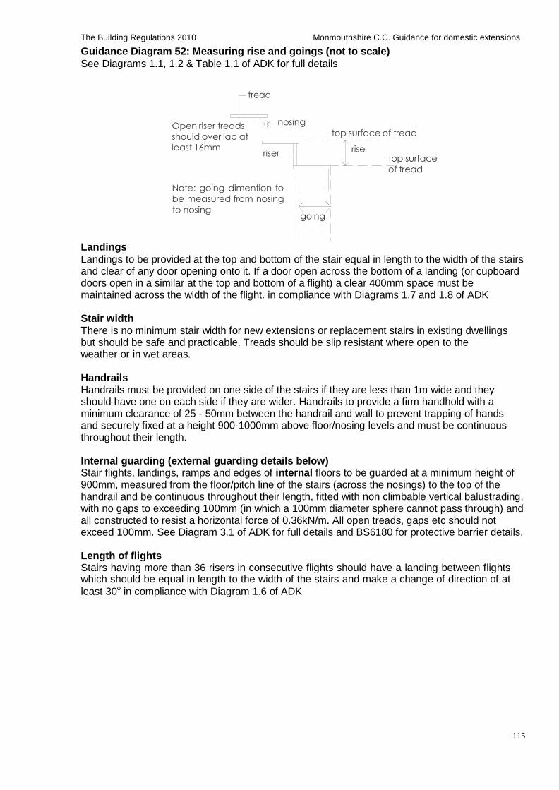
115
The Building Regulations 2010 Monmouthshire C.C. Guidance for domestic extensions
Guidance Diagram 52: Measuring rise and goings (not to scale)
See Diagrams 1.1, 1.2 & Table 1.1 of ADK for full details
tread
Open riser treads
should over lap at
least 16mm
nosing riser
top surface of tread
rise top surface
of tread
Note: going dimention to
be measured from nosing
to nosing
going
Landings
Landings to be provided at the top and bottom of the stair equal in length to the width of the stairs and clear of any door opening onto it. If a door open across the bottom of a landing (or cupboard doors open in a similar at the top and bottom of a flight) a clear 400mm space must be maintained across the width of the flight. in compliance with Diagrams 1.7 and 1.8 of ADK
Stair width
There is no minimum stair width for new extensions or replacement stairs in existing dwellings but should be safe and practicable. Treads should be slip resistant where open to the weather or in wet areas.
Handrails Handrails must be provided on one side of the stairs if they are less than 1m wide and they should have one on each side if they are wider. Handrails to provide a firm handhold with a minimum clearance of 25 - 50mm between the handrail and wall to prevent trapping of hands and securely fixed at a height 900-1000mm above floor/nosing levels and must be continuous throughout their length.
Internal guarding (external guarding details below) Stair flights, landings, ramps and edges of internal floors to be guarded at a minimum height of 900mm, measured from the floor/pitch line of the stairs (across the nosings) to the top of the handrail and be continuous throughout their length, fitted with non climbable vertical balustrading, with no gaps to exceeding 100mm (in which a 100mm diameter sphere cannot pass through) and all constructed to resist a horizontal force of 0.36kN/m. All open treads, gaps etc should not exceed 100mm. See Diagram 3.1 of ADK for full details and BS6180 for protective barrier details.
Length of flights Stairs having more than 36 risers in consecutive flights should have a landing between flights which should be equal in length to the width of the stairs and make a change of direction of at
least 30o in compliance with Diagram 1.6 of ADK
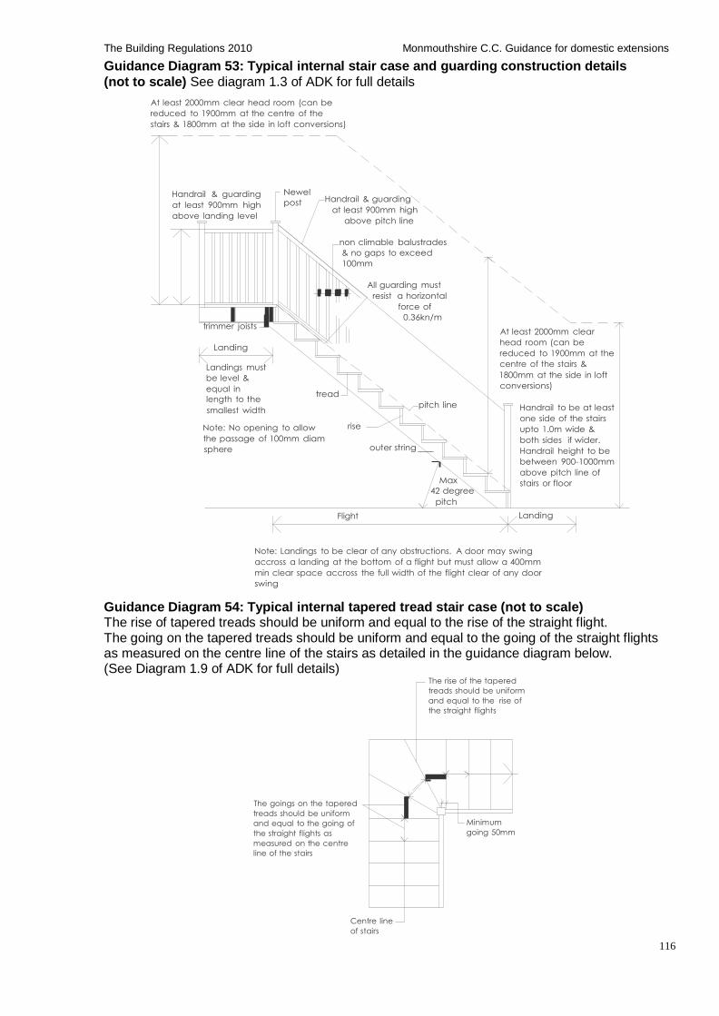
116
The Building Regulations 2010 Monmouthshire C.C. Guidance for domestic extensions
Guidance Diagram 53: Typical internal stair case and guarding construction details
(not to scale) See diagram 1.3 of ADK for full details
At least 2000mm clear head room (can be
reduced to 1900mm at the centre of the
stairs & 1800mm at the side in loft conversions)
Handrail & guarding
at least 900mm high
above landing level
Newel
post
Handrail & guarding
at least 900mm high
above pitch line
non climable balustrades
& no gaps to exceed
100mm
trimmer joists
Landing
Landings must
be level &
equal in
length to the
smallest width
Note: No opening to allow
tread
rise
All guarding must
resist a horizontal
force of
0.36kn/m
pitch line
At least 2000mm clear
head room (can be
reduced to 1900mm at the
centre of the stairs &
1800mm at the side in loft
conversions)
Handrail to be at least
one side of the stairs
upto 1.0m wide & the passage of 100mm diam
sphere
outer string
Max
both sides if wider.
Handrail height to be
between 900-1000mm
above pitch line of
stairs or floor 42 degree
pitch
Flight Landing
Note: Landings to be clear of any obstructions. A door may swing
accross a landing at the bottom of a flight but must allow a 400mm
min clear space accross the full width of the flight clear of any door
swing
Guidance Diagram 54: Typical internal tapered tread stair case (not to scale) The rise of tapered treads should be uniform and equal to the rise of the straight flight. The going on the tapered treads should be uniform and equal to the going of the straight flights as measured on the centre line of the stairs as detailed in the guidance diagram below. (See Diagram 1.9 of ADK for full details)
The rise of the tapered
treads should be uniform
and equal to the rise of
the straight flights
The goings on the tapered
treads should be uniform
and equal to the going of
the straight flights as
measured on the centre
line of the stairs
Minimum
going 50mm
Centre line
of stairs
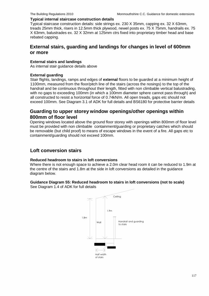
117
The Building Regulations 2010 Monmouthshire C.C. Guidance for domestic extensions
Typical internal staircase construction details
Typical staircase construction details: side strings ex. 230 X 35mm, capping ex. 32 X 63mm, treads 25mm thick, risers in 12.5mm thick plywood, newel posts ex. 75 X 75mm, handrails ex. 75 X 63mm, balustrades ex. 32 X 32mm at 125mm ctrs fixed into proprietary timber head and base rebated capping.
External stairs, guarding and landings for changes in level of 600mm or more
External stairs and landings As internal stair guidance details above
External guarding Stair flights, landings, ramps and edges of external floors to be guarded at a minimum height of 1100mm, measured from the floor/pitch line of the stairs (across the nosings) to the top of the handrail and be continuous throughout their length, fitted with non climbable vertical balustrading, with no gaps to exceeding 100mm (in which a 100mm diameter sphere cannot pass through) and all constructed to resist a horizontal force of 0.74kN/m. All open treads, gaps etc should not exceed 100mm. See Diagram 3.1 of ADK for full details and BS6180 for protective barrier details
Guarding to upper storey window openings/other openings within
800mm of floor level Opening windows located above the ground floor storey with openings within 800mm of floor level must be provided with non climbable containment/guarding or proprietary catches which should be removable (but child proof) to means of escape windows in the event of a fire. All gaps etc to containment/guarding should not exceed 100mm.
Loft conversion stairs Reduced headroom to stairs in loft conversions
Where there is not enough space to achieve a 2.0m clear head room it can be reduced to 1.9m at the centre of the stairs and 1.8m at the side in loft conversions as detailed in the guidance diagram below.
Guidance Diagram 55: Reduced headroom to stairs in loft conversions (not to scale)
See Diagram 1.4 of ADK for full details
Ceiling
1.9m
1.8m
Wall Handrail and guarding
to stairs
Half width
of stairs
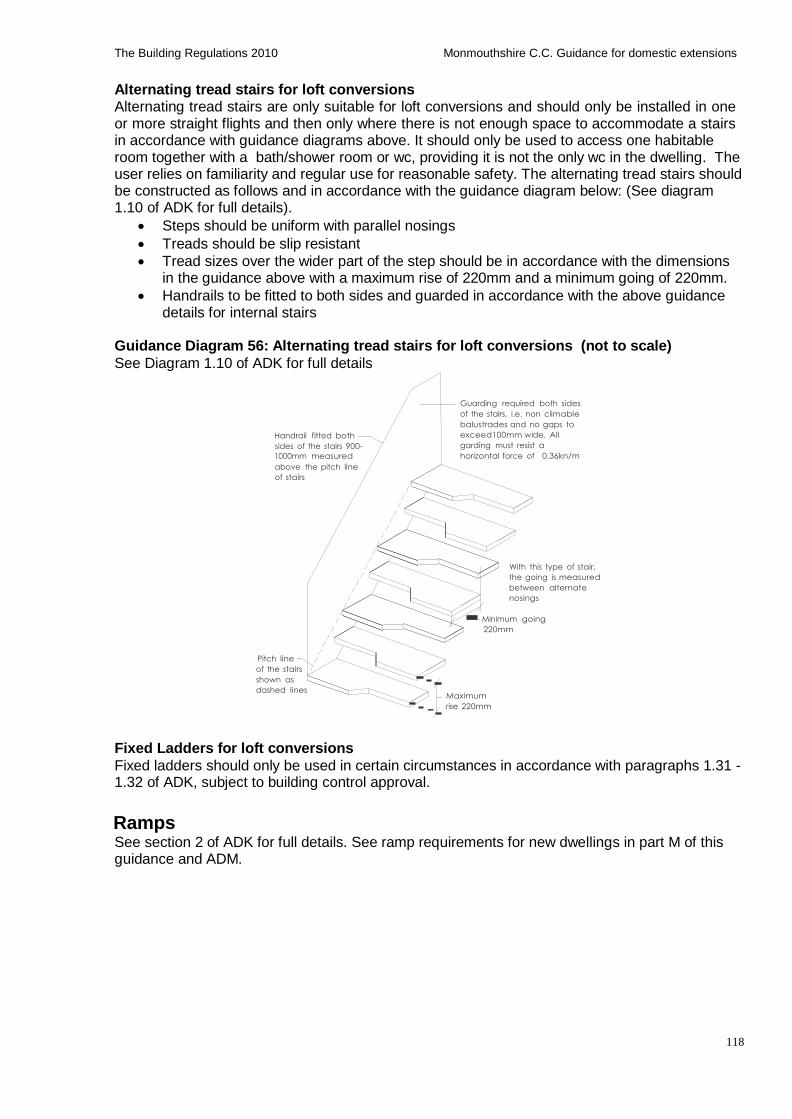
118
The Building Regulations 2010 Monmouthshire C.C. Guidance for domestic extensions
Alternating tread stairs for loft conversions Alternating tread stairs are only suitable for loft conversions and should only be installed in one or more straight flights and then only where there is not enough space to accommodate a stairs in accordance with guidance diagrams above. It should only be used to access one habitable room together with a bath/shower room or wc, providing it is not the only wc in the dwelling. The user relies on familiarity and regular use for reasonable safety. The alternating tread stairs should be constructed as follows and in accordance with the guidance diagram below: (See diagram 1.10 of ADK for full details).
Steps should be uniform with parallel nosings
Treads should be slip resistant
Tread sizes over the wider part of the step should be in accordance with the dimensions in the guidance above with a maximum rise of 220mm and a minimum going of 220mm.
Handrails to be fitted to both sides and guarded in accordance with the above guidance details for internal stairs
Guidance Diagram 56: Alternating tread stairs for loft conversions (not to scale)
See Diagram 1.10 of ADK for full details
Handrail fitted both
sides of the stairs 900-
1000mm measured
above the pitch line
of stairs
Guarding required both sides
of the stairs, i.e. non climable
balustrades and no gaps to
exceed100mm wide. All
garding must resist a
horizontal force of 0.36kn/m
With this type of stair,
the going is measured
between alternate
nosings
Minimum going
220mm
Pitch line
of the stairs
shown as
dashed lines
Maximum
rise 220mm
Fixed Ladders for loft conversions
Fixed ladders should only be used in certain circumstances in accordance with paragraphs 1.31 - 1.32 of ADK, subject to building control approval.
Ramps See section 2 of ADK for full details. See ramp requirements for new dwellings in part M of this guidance and ADM.
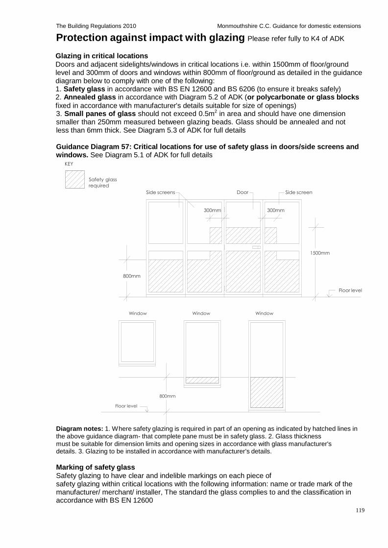
119
The Building Regulations 2010 Monmouthshire C.C. Guidance for domestic extensions
Protection against impact with glazing Please refer fully to K4 of ADK
Glazing in critical locations
Doors and adjacent sidelights/windows in critical locations i.e. within 1500mm of floor/ground level and 300mm of doors and windows within 800mm of floor/ground as detailed in the guidance diagram below to comply with one of the following: 1. Safety glass in accordance with BS EN 12600 and BS 6206 (to ensure it breaks safely) 2. Annealed glass in accordance with Diagram 5.2 of ADK (or polycarbonate or glass blocks
fixed in accordance with manufacturer's details suitable for size of openings) 3. Small panes of glass should not exceed 0.5m2 in area and should have one dimension smaller than 250mm measured between glazing beads. Glass should be annealed and not less than 6mm thick. See Diagram 5.3 of ADK for full details
Guidance Diagram 57: Critical locations for use of safety glass in doors/side screens and windows. See Diagram 5.1 of ADK for full details
KEY
Safety glass
required
Side screens
Door
Side screen
300mm 300mm
1500mm
800mm
Floor level
Window Window Window
800mm
Floor level
Diagram notes: 1. Where safety glazing is required in part of an opening as indicated by hatched lines in the above guidance diagram- that complete pane must be in safety glass. 2. Glass thickness must be suitable for dimension limits and opening sizes in accordance with glass manufacturer's details. 3. Glazing to be installed in accordance with manufacturer's details.
Marking of safety glass
Safety glazing to have clear and indelible markings on each piece of safety glazing within critical locations with the following information: name or trade mark of the manufacturer/ merchant/ installer, The standard the glass complies to and the classification in accordance with BS EN 12600
120
The Building Regulations 2010 Monmouthshire C.C. Guidance for domestic extensions
Part L1B: Conservation of fuel and power (Existing dwellings) Please refer fully to Approved Document L1B: Conservation of fuel and power in existing dwellings
(2010 edition with further 2010 amendments)
Contents Listed buildings, conservation areas and ancient monuments Areas of external windows, roof windows and doors New thermal elements External glazing Guidance Table 52: U-value requirements for external windows and doors including roof windows Guidance Table 53: U-values for double glazing Guidance Table 54: U-values for triple glazing- Pilkington EnergiKare glazing system Closing around window and door openings Sealing and draught proofing measures Energy efficient lighting Fixed internal lighting Fixed external lighting Insulation of pipe work to prevent freezing External walls, roofs, floors and swimming pool basin Guidance Table 55: U-values for external walls, roofs, floors and swimming pool basin Renovation/upgrading of existing thermal elements Guidance Table 56: Renovation/upgrading of existing thermal elements Consequential improvements (applies to existing buildings with a total useful floor area exceeding 1,000m
2)
Commissioning of fixed building services Providing information -building log book
Part L1B: Conservation of fuel and power (Existing dwellings)
Listed buildings, conservation areas and ancient monuments If the proposed energy efficiency requirements will unacceptably alter the character or appearance of a historic/listed building/ancient monument or building within a conservation area, then the energy efficiency standards may be exempt or improved to what is reasonably practical or acceptable and would not increase the risk of deterioration of the building fabric or fittings in consultation with the local planning authorities conservation officer in compliance with paragraphs 3.6- 3.14 of AD L1B.
Areas of external windows, roof windows and doors
Area of external windows, roof windows and doors should not exceed the sum of: (i) 25% of the floor area of the extension, plus (ii) the total area of any windows or doors which as a result of the extension works, no longer exists or are no longer exposed.
Notes: 1. Area of glazing less than 20% of the total floor area, may result in poor levels of daylight in the extension and dwelling. 2. Areas of glazing greater than 25% may be acceptable in certain circumstances, i.e. to make the extension consistent with the external appearance of the host building, in such cases the U- value of the window should be improved in accordance with Par 4.1b of ADL1B or other compensation measure as Par 4.4 -4.7 of ADL1B. 3. Where necessary, SAP calculations can be submitted to building control to confirm how compensating measures can provide flexibility where area of external windows, roof windows and doors exceed 25% of the floor area of the extension.
121
The Building Regulations 2010 Monmouthshire C.C. Guidance for domestic extensions
New thermal elements
External glazing External glazing insulation details to comply with U-values for external windows, doors and roof lights in compliance with paragraphs 4.19- 4.22 and Table 1 of ADL1B and guidance tables as follows: (Note: All external doors, windows, roof lights etc to be factory draft stripped)
Guidance Table 52: U-value requirements for external windows and doors including roof windows. See Table 1 of ADL1B for full details Fitting Insulation standard U-value not worse than:
Windows, roof window or roof light 1.6 (or Window energy rating (WER) as Band C of par 4.22 of ADL1B)
Doors with more than 50% glazing 1.8
Other doors 1.8
Replacement windows/doors As above or 1.2 centre pane- if external appearance of facade or character of the building is to be maintained
Guidance Table 53: U-values for double glazing
Pilkington Glass Outer pane Cavity/spacer/gas Inner pane U-value
IGU Optifloat 16mm air filled K-Glass 1.7
EnergiKare Optiwhite 16mm argon filled with aluminium spacer bar
K-Glass 1.5
Classic K-Glass OW
EnergiKare Optiwhite 16mm argon filled with warm edge spacer bar
K-Glass 1.5
Classic K-Glass OW
Guidance Table 54: U-values for triple glazing- Pilkington EnergiKare glazing system
Cavity Middle pane Cavity Inner pane U-value
Optiwhite 12mm argon K Glass T 12mm Argon K-Glass 1.0
Optiwhite 16mm argon K Glass T 16mm Argon K-Glass 0.8
Optiwhite 12mm argon K Glass OWT 12mm Argon K-Glass OW 1.0
Optiwhite 16mm argon K Glass OWT 16mm Argon K-Glass OW 0.8
Optiwhite 12mm Krypton K Glass OWT 12mm Krypton K-Glass OW 0.7
Closing around window and door openings Checked rebates should be constructed to window/door reveals or alternatively a proprietary finned insulated closers should be used. Checked rebates are where the outer skin masonry/skin projects across the inner skin by at least 25mm, the cavity is closed by an insulated closer and the window or door is fully sealed with mastic or similar externally.
Sealing and draught proofing measures All external door and window frames, service penetrations to walls, floors and ceilings, etc, should be sealed both internally and externally with proprietary sealing products such as proprietary waterproof mastic, expanding foam or mineral wool or tape to ensure air tightness.
Energy efficient lighting
Fixed internal lighting
Fixed internal energy efficient lighting in new extensions must not be less than 75% of all the fixed low energy light fittings (fixed lights or lighting units) in the main dwelling spaces (excluding cupboards and storage areas), fitted with lamps which must have a luminous efficiency greater than 45 lumens per circuit-watt and a total output greater than 400 lamp lumens. Light fittings to be either dedicated fittings which only take low energy lamps or standard fittings which take low energy lamps. (Note: light fittings with supplied power less than 5 circuit-watts are excluded from the overall count of the total number of light fittings)
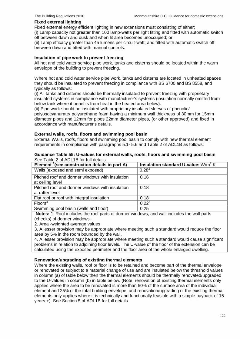
122
The Building Regulations 2010 Monmouthshire C.C. Guidance for domestic extensions
Fixed external lighting
Fixed external energy efficient lighting in new extensions must consisting of either; (i) Lamp capacity not greater than 100 lamp-watts per light fitting and fitted with automatic switch off between dawn and dusk and when lit area becomes unoccupied; or (ii) Lamp efficacy greater than 45 lumens per circuit-watt; and fitted with automatic switch off between dawn and fitted with manual controls.
Insulation of pipe work to prevent freezing
All hot and cold water service pipe work, tanks and cisterns should be located within the warm envelope of the building to prevent freezing.
Where hot and cold water service pipe work, tanks and cisterns are located in unheated spaces they should be insulated to prevent freezing in compliance with BS 6700 and BS 8558, and typically as follows: (i) All tanks and cisterns should be thermally insulated to prevent freezing with proprietary insulated systems in compliance with manufacturer's systems (insulation normally omitted from below tank where it benefits from heat in the heated area below). (ii) Pipe work should be insulated with proprietary insulated sleeves of phenolic/ polyosocyanurate/ polyurethane foam having a minimum wall thickness of 30mm for 15mm diameter pipes and 12mm for pipes 22mm diameter pipes, (or other approved) and fixed in accordance with manufacturer's details.
External walls, roofs, floors and swimming pool basin
External Walls, roofs, floors and swimming pool basin to comply with new thermal element requirements in compliance with paragraphs 5.1- 5.6 and Table 2 of ADL1B as follows:
Guidance Table 55: U-values for external walls, roofs, floors and swimming pool basin
See Table 2 of ADL1B for full details Element 1(see construction details in part A) Insulation standard U-value: W/m2.K
Walls (exposed and semi exposed) 0.282
Pitched roof and dormer windows with insulation at ceiling level
0.16
Pitched roof and dormer windows with insulation at rafter level
0.18
Flat roof or roof with integral insulation 0.18
Floors3 0.224
Swimming pool basin (walls and floor) 0.25
Notes: 1. Roof includes the roof parts of dormer windows, and wall includes the wall parts (cheeks) of dormer windows. 2. Area -weighted average values 3. A lesser provision may be appropriate where meeting such a standard would reduce the floor area by 5% in the room bounded by the wall. 4. A lesser provision may be appropriate where meeting such a standard would cause significant problems in relation to adjoining floor levels. The U-value of the floor of the extension can be calculated using the exposed perimeter and the floor area of the whole enlarged dwelling.
Renovation/upgrading of existing thermal elements
Where the existing walls, roof or floor is to be retained and become part of the thermal envelope or renovated or subject to a material change of use and are insulated below the threshold values in column (a) of table below then the thermal elements should be thermally renovated/upgraded to the U-values in column (b) in table below. (Note: renovation of existing thermal elements only applies where the area to be renovated is more than 50% of the surface area of the individual element and 25% of the total building envelope, and renovation/upgrading of the existing thermal elements only applies where it is technically and functionally feasible with a simple payback of 15 years +). See Section 5 of ADL1B for full details
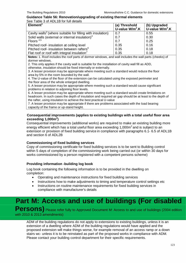
123
The Building Regulations 2010 Monmouthshire C.C. Guidance for domestic extensions
Guidance Table 56: Renovation/upgrading of existing thermal elements
See Table 3 of ADL1B for full details Element1
(a) Threshold U-value W/m2.K
(b) Upgraded U-value W/m2.K
Cavity walls2 (where suitable for filling with insulation)
Solid walls (external or internal insulation)3
Floors 4,5
Pitched roof- insulation at ceiling level
Pitched roof- insulation between rafters6
Flat roof or roof with integral insulation7
0.7 0.7 0.7 0.35 0.35 0.35
0.55 0.30 0.25 0.16 0.18 0.18
Notes: 1. Roof includes the roof parts of dormer windows, and wall includes the wall parts (cheeks) of dormer windows. 2. This only applies if the cavity wall is suitable for the installation of cavity wall fill as ADD, otherwise, insulation should be fixed internally or externally. 3. A lesser provision may be appropriate where meeting such a standard would reduce the floor area by 5% in the room bounded by the wall. 4. The U-value of the floor of the extension can be calculated using the exposed perimeter and the floor area of the whole enlarged dwelling. 5. A lesser provision may be appropriate where meeting such a standard would cause significant problems in relation to adjoining floor levels. 6. A lesser provision may be appropriate where meeting such a standard would create limitations on headroom. In such cases the depth of insulation and required air gap should be at least to the depth of the rafter, using insulation to achieve the best practical U-value 7. A lesser provision may be appropriate if there are problems associated with the load bearing capacity of the frame or up-stand height.
Consequential improvements (applies to existing buildings with a total useful floor area exceeding 1,000m2) Consequential improvements (additional works) are required to make an existing building more
energy efficient which has a total useful floor area exceeding 1,000m2 and is subject to an extension or provision of fixed building service in compliance with paragraphs 6.1- 6.5 of ADL1B and section 6 of ADL2B
Commissioning of fixed building services Copy of commissioning certificate for fixed building services is to be sent to Building control within 5 days of completion of the commissioning work being carried out (or within 30 days for works commissioned by a person registered with a competent persons scheme)
Providing information -building log book
Log book containing the following information is to be provided in the dwelling on completion:
Operating and maintenance instructions for fixed building services
Instructions how to make adjustments to timing and temperature control settings etc
Instructions on routine maintenance requirements for fixed building services in compliance with manufacturer's details
Part M: Access and use of buildings (For disabled Persons) Please refer fully to Approved Document M: Access to and use of buildings (2004 edition
with 2010 & 2013 amendments)
ADM of the building regulations do not apply to extensions to existing buildings, unless it is an extension of a dwelling where ADM of the building regulations would have applied and the proposed extension will make things worse, for example removal of an access ramp or a down stairs wc- unless it is to be reinstated as part of the proposed works in compliance with ADM. Please contact your building control department for their specific requirements.
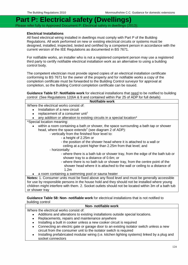
124
The Building Regulations 2010 Monmouthshire C.C. Guidance for domestic extensions
Part P: Electrical safety (Dwellings) Please refer fully to Approved Document P: Electrical safety in dwellings (2013);
Electrical Installations All fixed electrical wiring installed in dwellings must comply with Part P of the Building Regulations. All work performed on new or existing electrical circuits or systems must be designed, installed, inspected, tested and certified by a competent person in accordance with the current version of the IEE Regulations as documented in BS 7671.
For notifiable works, an installer who is not a registered competent person may use a registered third party to certify notifiable electrical installation work as an alternative to using a building control body.
The competent electrician must provide signed copies of an electrical installation certificate conforming to BS 7671 for the owner of the property and for notifiable works a copy of the completion certificate must be forwarded to the Building Control surveyor for approval at completion, so the Building Control completion certificate can be issued.
Guidance Table 57: Notifiable work for electrical installations that need to be notified to building
control (See Regulations 12(6A & 9 and contained within Par 25 of ADP for full details)
Notifiable work
Where the electrical works consist of:
Installation of a new circuit
replacement of a consumer unit1
any addition or alteration to existing circuits in a special location* *Special location meaning:
within a room containing a bath or shower, the space surrounding a bath tap or shower head, where the space extends2 (see diagram 2 of ADP):
- vertically from the finished floor level to: - a height of 2.25m or - the position of the shower head where it is attached to a wall or
ceiling at a point higher than 2.25m from that level; and - horizontally:
- where there is a bath tub or shower tray, from the edge of the bath tub or shower tray to a distance of 0.6m; or
- where there is no bath tub or shower tray, from the centre point of the shower head where it is attached to the wall or ceiling to a distance of 1.2m
a room containing a swimming pool or sauna heater Notes: 1. Consumer units must be fixed above any flood level and must be generally accessible for use by responsible persons in the house hold and they should not be installed where young children might interfere with them. 2. Socket outlets should not be located within 3m of a bath tub or shower tray
Guidance Table 58: Non- notifiable work for electrical installations that is not notified to building control
Where the electrical works consist of:
Non- notifiable work
Additions and alterations to existing installations outside special locations. Replacements, repairs and maintenance anywhere Installing a built in cooker unless a new cooker circuit is required
Connecting an electric gate or garage door to an existing isolator switch unless a new circuit from the consumer unit to the isolator switch is required
Installing prefabricated modular wiring (i.e. kitchen lighting systems) linked by a plug and socket connectors
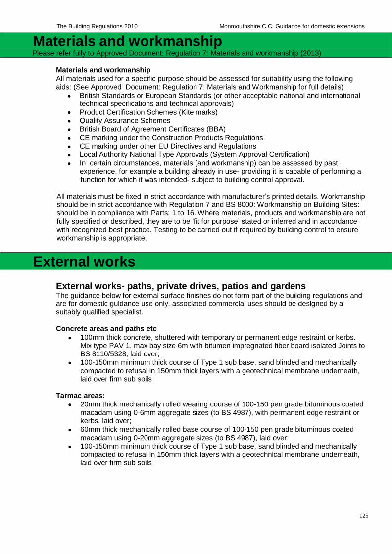
125
The Building Regulations 2010 Monmouthshire C.C. Guidance for domestic extensions
Materials and workmanship Please refer fully to Approved Document: Regulation 7: Materials and workmanship (2013)
Materials and workmanship
All materials used for a specific purpose should be assessed for suitability using the following aids: (See Approved Document: Regulation 7: Materials and Workmanship for full details)
British Standards or European Standards (or other acceptable national and international technical specifications and technical approvals)
Product Certification Schemes (Kite marks)
Quality Assurance Schemes British Board of Agreement Certificates (BBA)
CE marking under the Construction Products Regulations CE marking under other EU Directives and Regulations
Local Authority National Type Approvals (System Approval Certification)
In certain circumstances, materials (and workmanship) can be assessed by past experience, for example a building already in use- providing it is capable of performing a function for which it was intended- subject to building control approval.
All materials must be fixed in strict accordance with manufacturer’s printed details. Workmanship should be in strict accordance with Regulation 7 and BS 8000: Workmanship on Building Sites: should be in compliance with Parts: 1 to 16. Where materials, products and workmanship are not fully specified or described, they are to be ‘fit for purpose’ stated or inferred and in accordance with recognized best practice. Testing to be carried out if required by building control to ensure workmanship is appropriate.
External works
External works- paths, private drives, patios and gardens The guidance below for external surface finishes do not form part of the building regulations and are for domestic guidance use only, associated commercial uses should be designed by a suitably qualified specialist.
Concrete areas and paths etc
100mm thick concrete, shuttered with temporary or permanent edge restraint or kerbs. Mix type PAV 1, max bay size 6m with bitumen impregnated fiber board isolated Joints to BS 8110/5328, laid over;
100-150mm minimum thick course of Type 1 sub base, sand blinded and mechanically compacted to refusal in 150mm thick layers with a geotechnical membrane underneath, laid over firm sub soils
Tarmac areas:
20mm thick mechanically rolled wearing course of 100-150 pen grade bituminous coated macadam using 0-6mm aggregate sizes (to BS 4987), with permanent edge restraint or kerbs, laid over;
60mm thick mechanically rolled base course of 100-150 pen grade bituminous coated macadam using 0-20mm aggregate sizes (to BS 4987), laid over;
100-150mm minimum thick course of Type 1 sub base, sand blinded and mechanically
compacted to refusal in 150mm thick layers with a geotechnical membrane underneath, laid over firm sub soils
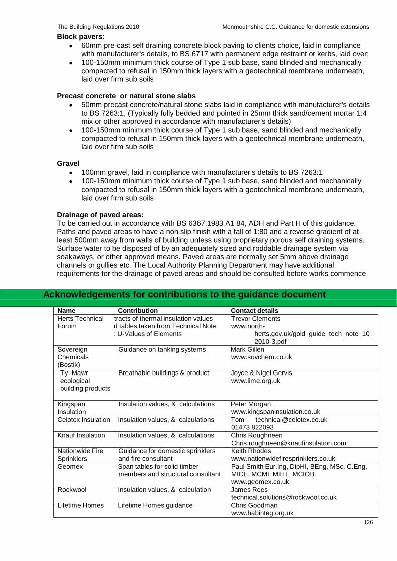
126
The Building Regulations 2010 Monmouthshire C.C. Guidance for domestic extensions
Block pavers:
60mm pre-cast self draining concrete block paving to clients choice, laid in compliance with manufacturer's details, to BS 6717 with permanent edge restraint or kerbs, laid over;
100-150mm minimum thick course of Type 1 sub base, sand blinded and mechanically compacted to refusal in 150mm thick layers with a geotechnical membrane underneath, laid over firm sub soils
Precast concrete or natural stone slabs
50mm precast concrete/natural stone slabs laid in compliance with manufacturer's details to BS 7263:1, (Typically fully bedded and pointed in 25mm thick sand/cement mortar 1:4 mix or other approved in accordance with manufacturer's details)
100-150mm minimum thick course of Type 1 sub base, sand blinded and mechanically compacted to refusal in 150mm thick layers with a geotechnical membrane underneath, laid over firm sub soils
Gravel
100mm gravel, laid in compliance with manufacturer's details to BS 7263:1 100-150mm minimum thick course of Type 1 sub base, sand blinded and mechanically
compacted to refusal in 150mm thick layers with a geotechnical membrane underneath, laid over firm sub soils
Drainage of paved areas: To be carried out in accordance with BS 6367:1983 A1 84, ADH and Part H of this guidance. Paths and paved areas to have a non slip finish with a fall of 1:80 and a reverse gradient of at least 500mm away from walls of building unless using proprietary porous self draining systems. Surface water to be disposed of by an adequately sized and roddable drainage system via soakaways, or other approved means. Paved areas are normally set 5mm above drainage channels or gullies etc. The Local Authority Planning Department may have additional requirements for the drainage of paved areas and should be consulted before works commence.
Acknowledgements for contributions to the guidance document
Name Contribution Contact details
Herts Technical Forum
tracts of thermal insulation values d tables taken from Technical Note : U-Values of Elements
Trevor Clements www.north-
herts.gov.uk/gold_guide_tech_note_10_
2010-3.pdf
Sovereign Chemicals (Bostik)
Ty -Mawr ecological building products
Guidance on tanking systems Mark Gillen www.sovchem.co.uk
Breathable buildings & product Joyce & Nigel Gervis
www.lime.org.uk
Kingspan
Insulation Insulation values, & calculations Peter Morgan
www.kingspaninsulation.co.uk
Celotex Insulation Insulation values, & calculations Tom [email protected] 01473 822093
Knauf Insulation Insulation values, & calculations Chris Roughneen
Nationwide Fire
Sprinklers Guidance for domestic sprinklers and fire consultant
Keith Rhodes www.nationwidefiresprinklers.co.uk
Geomex Span tables for solid timber members and structural consultant
Paul Smith Eur.Ing, DipHI, BEng, MSc, C.Eng, MICE, MCMI, MIHT, MCIOB. www.geomex.co.uk
Rockwool Insulation values, & calculation James Rees [email protected]
Lifetime Homes Lifetime Homes guidance Chris Goodman www.habinteg.org.uk
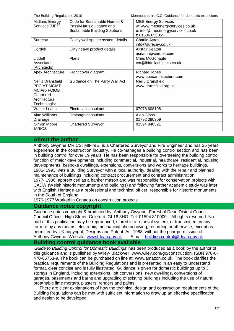
127
The Building Regulations 2010 Monmouthshire C.C. Guidance for domestic extensions
Midland Energy Services (MES)
Code for Sustainable Homes & PassivHaus guidance and Sustainable Building Solutions
MES Energy Services w: www.mesenergyservices.co.uk e: info@ mesenergyservices.co.uk t: 01636 653055
Surecav Cavity wall spacer system details Charlie Ayres [email protected]
Cordek Clay heave product details Alistair Seaton [email protected]
Liddell Associates (Architects)
Plans Chris McGonagle [email protected]
Apex Architecture Front cover diagram Richard Jones www.apexarchitecture.com
Neil J Dransfield PPCIAT MCIAT MCIArb FCIOB Chartered Architectural Technologist
Guidance on The Party Wall Act Neil J Dransfield www.dransfield.org.uk
Walter Leach Electrical consultant 07976 608108
Alan Williams Drainage
Drainage consultant Alan Glass 01792 390309
Simon Moore MRICS
Chartered Surveyor 01594 840521
About the author Anthony Gwynne MRICS; MIFireE, is a Chartered Surveyor and Fire Engineer and has 35 years experience in the construction industry. He co-manages a building control section and has been in building control for over 19 years. He has been responsible for overseeing the building control function of major developments including commercial, industrial, healthcare, residential, housing developments, bespoke dwellings, extensions, conversions and works to heritage buildings. 1986- 1993; was a Building Surveyor with a local authority, dealing with the repair and planned maintenance of buildings including contract procurement and contract administration. 1977- 1986; apprenticed as a banker mason and was responsible for conservation projects with CADW (Welsh historic monuments and buildings) and following further academic study was later with English Heritage as a professional and technical officer, responsible for historic monuments in the South of England. 1976-1977 Worked in Canada on construction projects
Guidance notes copyright Guidance notes copyright & produced by: Anthony Gwynne, Forest of Dean District Council, Council Offices, High Street, Coleford, GL16 8HG. Tel: 01594 810000. All rights reserved. No part of this publication may be reproduced, stored in a retrieval system, or transmitted, in any form or by any means, electronic, mechanical photocopying, recording or otherwise, except as permitted by UK copyright, Designs and Patent Act 1988, without the prior permission of Anthony Gwynne. Website: www.fdean.gov.uk E mail: [email protected]
Building control guidance book available 'Guide to Building Control for Domestic Buildings' has been produced as a book by the author of this guidance and is published by Wiley- Blackwell. www.wiley.com/go/construction. ISBN 978-0- 470-65753-9. The book can be purchased on line at: www.amazon.co.uk. The book clarifies the practical requirements of the Building Regulations and is presented in an easy to understand format, clear concise and is fully illustrated. Guidance is given for domestic buildings up to 3 storeys in England, including extensions, loft conversions, new dwellings, conversions of garages, basements and barns and upgrading of existing buildings including the use of natural breathable lime mortars, plasters, renders and paints.
There are clear explanations of how the technical design and construction requirements of the Building Regulations can be met with sufficient information to draw up an effective specification and design to be developed.