Embed Size (px)
Citation preview
PCM Reference: 240-45920887
SCOT Study Committee Number/Name: Power Plant Operating
Standard Technology
Title: STANDARD FOR THE LABELLING OF ELECTRICAL EQUIPMENT WITHIN ESKOM WIRES NETWORKS
Unique Identifier: 240-120804300
Alternative Reference Number: Eskasaan0 / 41-1009 / 34-1439 / 41-655
Area of Applicability: Engineering
Documentation Type: Standard
Revision: 2
Total Pages: 63
Next Review Date: October 2023
Disclosure Classification: Controlled Disclosure
Compiled by Approved by Authorized by
David Ntombela
Consultant
Andre Bekker
Middle Manager Design Engineering
Amelia Mtshali
Senior Manager Power Delivery Engineering
Date: 19/02/2018 Date: Date:
Supported by SCOT/SC
Dumisani Mtolo
SCOT/SC Chairperson
Date:
Document Classification: Controlled Disclosure
STANDARD FOR THE LABELLING OF ELECTRICAL EQUIPMENT WITHIN ESKOM WIRES NETWORKS
Unique Identifier: 240-120804300
Revision: 2
Page: 2 of 63
ESKOM COPYRIGHT PROTECTED
When downloaded from the WEB, this document is uncontrolled and the responsibility rests with the user
to ensure it is in line with the authorized version on the WEB.
Content
Page
1. Introduction .................................................................................................................................................. 5
2. Supporting clauses ...................................................................................................................................... 5 2.1 Scope ................................................................................................................................................. 5
2.1.1 Purpose .................................................................................................................................. 5 2.1.2 Applicability ............................................................................................................................ 5
2.2 Normative/informative references ...................................................................................................... 5 2.2.1 Normative ............................................................................................................................... 5 2.2.2 Informative ............................................................................................................................. 6
2.3 Definitions ........................................................................................................................................... 6 2.3.1 General .................................................................................................................................. 6 2.3.2 Disclosure classification ......................................................................................................... 6
2.4 Abbreviations ...................................................................................................................................... 6 2.5 Roles and responsibilities .................................................................................................................. 7 2.6 Process for monitoring ....................................................................................................................... 7 2.7 Related/supporting documents .......................................................................................................... 7
3. Requirements .............................................................................................................................................. 8 3.1 General ............................................................................................................................................... 8
3.1.1 Substation Names and Line Codes Registration ................................................................... 8 3.1.2 Basic Labelling Requirements ............................................................................................... 8 3.1.3 Safety ..................................................................................................................................... 8 3.1.4 Language ............................................................................................................................... 9 3.1.5 Spare / Unused Panels .......................................................................................................... 9 3.1.6 Labelling Abbreviations Usage .............................................................................................. 9
3.2 Substation Labelling ........................................................................................................................... 9 3.2.1 Labelling Philosophy .............................................................................................................. 9 3.2.2 Label Types and Colours ..................................................................................................... 10 3.2.3 Substation Equipment .......................................................................................................... 10
3.3 Overhead Labelling .......................................................................................................................... 19 3.3.1 Labelling Philosophy ............................................................................................................ 19 3.3.2 Label types and colours ....................................................................................................... 20 3.3.3 Overhead Lines Labels ........................................................................................................ 21 3.3.4 MV Operating and Equipment Labelling .............................................................................. 22 3.3.5 LV Operating point labelling ................................................................................................. 24
3.4 Cable Underground Systems Labelling............................................................................................ 24 3.4.1 MV Labelling Philosophy ...................................................................................................... 24 3.4.2 LV Labelling Philosophy ....................................................................................................... 25 3.4.3 Cable Route Markers ........................................................................................................... 26
4. Installation.................................................................................................................................................. 26 4.1 Position of tower labels on tower / structure / pole .......................................................................... 26 4.2 Position of line crossing labels on tower .......................................................................................... 26 4.3 Methods of attaching labels onto towers / structures ....................................................................... 26
5. Related Documents ................................................................................................................................... 27
6. Forms, Records and Certificates ............................................................................................................... 27
7. Authorization .............................................................................................................................................. 27
Document Classification: Controlled Disclosure
STANDARD FOR THE LABELLING OF ELECTRICAL EQUIPMENT WITHIN ESKOM WIRES NETWORKS
Unique Identifier: 240-120804300
Revision: 2
Page: 3 of 63
ESKOM COPYRIGHT PROTECTED
When downloaded from the WEB, this document is uncontrolled and the responsibility rests with the user
to ensure it is in line with the authorized version on the WEB.
8. Revisions ................................................................................................................................................... 27
9. Development team .................................................................................................................................... 28
10. Acknowledgements ................................................................................................................................... 28
Annex A – Approved Labelling Abbreviations .................................................................................................. 29
Annex B – Busbars and Associated Equipment ............................................................................................... 32
Annex C – GIS & Section Isolators ................................................................................................................... 33
Annex D – Typical Jericho System ................................................................................................................... 34
Annex E – Transformers and Associated Equipment ....................................................................................... 35
Annex F – Transformers and Associated Equipment – Double banked Transformers .................................... 36
Annex G – Transformers and associated equipment – line banks ................................................................... 37
Annex H – Transformers and associated equipment ....................................................................................... 38
Annex I – Feeders and Associated Equipment ................................................................................................ 39
Annex J – Feeders and Associated Equipment – Tee Line Feeders ............................................................... 40
Annex K – Busbars and Associated Equipment ............................................................................................... 41
Annex L – Busbars and Associated Equipment – Power Stations (Station Transformer and Generator Transformer) .............................................................................................................................................. 42
Annex M – Busbars and Associated Equipment – Shunt Capacitors and Reactor .......................................... 43
Annex N – Busbars and Associated Equipment – Twin Reactors ................................................................... 44
Annex O – Transformer Bays with Fault Current Limiting Reactor .................................................................. 45
Annex P – Transformers and Associated Equipment - Line Banks ................................................................. 46
Annex Q – Transformers and Associated Equipment _Single-Phase Traction Supply ................................... 47
Annex R – Bus Section with Fault Current Limiting Reactor ............................................................................ 48
Annex S – Bus Coupler with Fault Current Limiting Reactor ............................................................................ 49
Annex T – Transformers and Associated Equipment (Secondary) – 765/400 kV Station Auxiliary Transformers ............................................................................................................................................. 50
Annex U – Feeders and Associated Equipment with Line Reactor .................................................................. 51
Annex V – Feeder Bays Feeders with Emergency Bypasses at Lower Voltages ............................................ 52
Annex W – Transformer Tertiary Bays Auxiliary Transformers ........................................................................ 53
Annex X – Transformer Tertiary Bays with Step up, Step down and Auxiliary Transformers .......................... 54
Annex Y – Transformer Tertiary Bays with Reactor and Voltage Regulator .................................................... 55
Annex Z – Series Capacitor Station ................................................................................................................. 56
Annex AA – Static Var Compensators (SVC) ................................................................................................... 57
Annex BB – 765 kV BKR and a half with Reactor Transfer Busbar ................................................................. 58
Annex CC – Tower / Structure / Pole Label Position ........................................................................................ 63
Figures
Figure 1: Mini-sub and RMU Labelling ............................................................................................................. 24
Document Classification: Controlled Disclosure
STANDARD FOR THE LABELLING OF ELECTRICAL EQUIPMENT WITHIN ESKOM WIRES NETWORKS
Unique Identifier: 240-120804300
Revision: 2
Page: 4 of 63
ESKOM COPYRIGHT PROTECTED
When downloaded from the WEB, this document is uncontrolled and the responsibility rests with the user
to ensure it is in line with the authorized version on the WEB.
Tables
Table 1: Diameter Naming / Voltage Level ....................................................................................................... 16
Document Classification: Controlled Disclosure
STANDARD FOR THE LABELLING OF ELECTRICAL EQUIPMENT WITHIN ESKOM WIRES NETWORKS
Unique Identifier: 240-120804300
Revision: 2
Page: 5 of 63
ESKOM COPYRIGHT PROTECTED
When downloaded from the WEB, this document is uncontrolled and the responsibility rests with the user
to ensure it is in line with the authorized version on the WEB.
1. Introduction
This standard is based on and it complies with OHS Act requirements; it was originally prepared / compiled to standardize the labelling of high voltage Equipment within Eskom Wires Networks.
Labelling is a statutory requirement of the Occupational Health and Safety Act (OHS Act) No 85 of 1993. The act states that all controlling apparatus shall be permanently marked so as to identify the system or part of the system it is made up of.
2. Supporting clauses
2.1 Scope
2.1.1 Purpose
The purpose of this document is to standardize labelling of all equipment in Eskom Wires substations, Cable Network and Overhead Lines.
2.1.2 Applicability
This standard applies to all labelling in the Eskom Wires Networks. Retrofitting of labels to meet the requirements of this standard is not mandatory for existing installations but when significant additions / alterations / refurbishment to a substation or line takes place all labelling shall be changed to meet this standard. Where an existing label does not uniquely identify the relevant equipment, or constitutes a possible danger, the label shall be changed immediately.
2.2 Normative/informative references
Parties using this document shall apply the most recent edition of the documents listed in the following paragraphs.
2.2.1 Normative
[1] Occupational Health and Safety Act and Regulations (OHS Act);
[2] 240-114967625, Operating Regulations for High Voltage Systems (ORHVS);
[3] ISO 9001, 2000 Quality Management Systems;
[4] D-DT-8012, Marker Cable Route Concrete;
[5] 0.54/404, Electrical equipment enamelled labels details;
[6] 240-82737065: MV/LV Pole Numbering;
[7] DDT-5050: MV/LV Line Labelling;
[8] 0.54/5577, Electrical equipment enamelled labels text layout;
[9] 240-75660336, The Standard for Design, Manufacturing and Installation of Eskom Wires Business Equipment Labels;
[10] 240-89556857, Distribution Group’s Specific Representation Of Operating Diagrams In The Field – Station Electric Diagrams;
[11] 240-77297024, Standard For Operating Diagrams For Eskom Transmission Substations;
[12] 240-56065131, Specification for 11 kV to 33kV Withdrawable Pattern Air-Insulated Indoor Primary Switchgear Standard.
[13] 240-62629353, Specification For Panel Labelling Standard;
[14] 240-56362221, Standard For Safety Signs Used In DC Applications; and
Document Classification: Controlled Disclosure
STANDARD FOR THE LABELLING OF ELECTRICAL EQUIPMENT WITHIN ESKOM WIRES NETWORKS
Unique Identifier: 240-120804300
Revision: 2
Page: 6 of 63
ESKOM COPYRIGHT PROTECTED
When downloaded from the WEB, this document is uncontrolled and the responsibility rests with the user
to ensure it is in line with the authorized version on the WEB.
[15] 240-80139037, Statutory Safety Signs In Transmission Sub-Stations And Buildings.
2.2.2 Informative
None
2.3 Definitions
All definitions in the OHS Act 85 and 240-114967625 as well as the following are applicable:
2.3.1 General
Definition Description
Substation Means a site on which any transforming, switching or linking apparatus forming part of the power system is situated and on which no active power-generating equipment other than auxiliary generating sets is situated. The term ‘substation’ includes distribution stations and switching stations.
Outdoor Switching stations
Means a site situated outdoors where only switching and linking takes place. No transforming takes place
Indoor Switching stations
Means a site situated indoors where only switching and linking takes place. No transforming takes place.
Power Equipment All equipment that are operating or functioning at system voltage above 1000 V i.e. 6.6 kV, 132 kV, 400 kV etc.
Auxiliary Equipment All equipment that are operating or functioning at system voltage below 1000 V
Greenfield Substations Development of a substation on land that had never been used before. The term also relates to creating a substation from the ground up without the need to consider previous work.
Auxiliary Transformer A transformer intended to provide supply to the auxiliary equipment such as main transformer fans, protection and control equipment, building lighting, floodlighting, etc. with 400V
Secondary Transformer A transformer (not an NEC or AUX) that is directly connected to another transformer and is intended to supply the load external to the substation or auxiliary transformers inside the substation.
Primary Transformer Substation main transformers
2.3.2 Disclosure classification
Controlled disclosure: controlled disclosure to external parties (either enforced by law, or discretionary).
2.4 Abbreviations
All abbreviations in ORHVS and NRS 082, as well as the following, are applicable and a comprehensive list of abbreviations which could be used on labels is detailed in Annexure A:
Abbreviation Description
AUX Auxiliary
BIPM Business Integration and Performance Management
DCB Disconnecting Circuit Breaker
DRG Drawing
Document Classification: Controlled Disclosure
STANDARD FOR THE LABELLING OF ELECTRICAL EQUIPMENT WITHIN ESKOM WIRES NETWORKS
Unique Identifier: 240-120804300
Revision: 2
Page: 7 of 63
ESKOM COPYRIGHT PROTECTED
When downloaded from the WEB, this document is uncontrolled and the responsibility rests with the user
to ensure it is in line with the authorized version on the WEB.
Abbreviation Description
DX Distribution
HMI Human Machine Interface
LV Low Voltage
OHS Act Occupational Health and Safety Act
ORHVS Operating Regulations for High Voltage Systems
SAP Systems Applications and Products (software package)
SCADA System Control And Dispatch Application
SED Substation Engineering Department
SpM&S Specialized Maintenance and Support
TX Transmission
2.5 Roles and responsibilities
a) The labelling of all electrical equipment in terms of this standard shall be the responsibility of the relevant Managers (HV Plant Managers / O & M Managers) or their delegated appointee.
b) The maintenance of all electrical network labelling documents and corresponding diagrams and drawings in terms of this standard is the responsibility of Group Technology Division.
c) The purchase and fitting of all tower labels on lines which are Wires assets, when changes or additions are made, is the responsibility of the Operating Units (OUs).
d) The designated person or his delegate shall ensure that all labels comply with the requirements in this standard.
e) The field operator shall ensure that the electrical equipment labels correspond with the operating diagram before commencing with operating.
f) It is the responsibility of the Project Manager / GMR 2.1 to ensure that the correct labels are erected and corresponds with the operating diagram and control equipment.
g) Audits need to be conducted by BIPM and SpM&S, to assess the condition and legibility of electrical equipment labels, operating diagrams and control equipment (SCADA, HMI, SAP), in Wires to comply with this standard.
2.6 Process for monitoring
Document number Document title
240-45920887 Process Control Manual (PCM) for Manage Maintenance Base
240-52380420 Steering Committee of Technologies (SCOT) Standards Development and Change Implementation Procedure
2.7 Related/supporting documents
This standard supersedes all other application standards pertaining to the equipment labels in Eskom Transmission and Distribution Substations including the following:
Document number Document title

Document Classification: Controlled Disclosure
STANDARD FOR THE LABELLING OF ELECTRICAL EQUIPMENT WITHIN ESKOM WIRES NETWORKS
Unique Identifier: 240-120804300
Revision: 2
Page: 8 of 63
ESKOM COPYRIGHT PROTECTED
When downloaded from the WEB, this document is uncontrolled and the responsibility rests with the user
to ensure it is in line with the authorized version on the WEB.
Document number Document title
DST_34-1439 Standard For The Labelling Of Substations And Networks Labels
TST_41-1009 Standard For The Labelling Of Outdoor High Voltage Equipment Within Eskom Transmission Substations
ESKASAAN0 Standard For The Labelling Of High Voltage Equipment
3. Requirements
3.1 General
No variations from this standard shall be allowed in any form unless approved by the Eskom Wires Business.
3.1.1 Substation Names and Line Codes Registration
a) All substations names, lines names and line codes shall be managed according to Wires Business data requirements to avoid duplications.
3.1.2 Basic Labelling Requirements
a) The basic requirements to follow when labelling the electrical equipment shall be as follows:
Labelling composition shall be as per the approved abbreviations within the Wires business.
Labelling shall provide unique identification of individual electrical equipment within a given substation or network.
Labelling of electrical equipment shall not be in conflict with any other label within a given substation or network.
In substations where stations have transformers of differing ratios, the transformers with the highest primary voltage, highest secondary voltage and have the lowest voltage ratio in the substation shall be numbered from 1 to 9; and the transformers with the next highest primary and secondary voltages with the next lowest voltage ratio shall be numbered from 11 to 19 etc.
3.1.3 Safety
3.1.3.1 Statutory Requirements
The OHS Act No. 85 of 1993, Electrical Machinery Regulations 7 (4) states: “The user shall mark or label all controlling apparatus permanently so as to identify the system or part of the system on the electrical machinery which it controls, and where such control apparatus is accessible from the front and back these markings shall be on both the front and the back”.
3.1.3.2 For statutory safety sign and battery rooms refer to the applicable standards i.e.:
The Standard for Design, Manufacturing and Installation of Eskom Wires Business Equipment Labels (240-75660336) Annexure A;
The following references are applicable for statutory safety sign and battery rooms:
o 240-62629353, Specification For Panel Labelling Standard
o 240-56362221, Standard For Safety Signs Used In DC Applications
o 240-80139037, Statutory Safety Signs In Transmission Sub-Stations And Buildings
Document Classification: Controlled Disclosure
STANDARD FOR THE LABELLING OF ELECTRICAL EQUIPMENT WITHIN ESKOM WIRES NETWORKS
Unique Identifier: 240-120804300
Revision: 2
Page: 9 of 63
ESKOM COPYRIGHT PROTECTED
When downloaded from the WEB, this document is uncontrolled and the responsibility rests with the user
to ensure it is in line with the authorized version on the WEB.
3.1.4 Language
The wording on labels shall be in English.
3.1.5 Spare / Unused Panels
Where a panel/bay or any apparatus is permanently taken out of service and not part of the system, all such labels shall be removed.
Spare panel/bay or apparatus shall be labelled as such.
3.1.6 Labelling Abbreviations Usage
a) All substation and feeder names can be written out in full without abbreviation with the exception of equipment type being referred to e.g. CRAIGHALL 1 TRFR 1 400/275/22kV not CRAIGHALL 1 TRANSFORMER 1 400/275/22kV.
b) All equipment classes / names shall be abbreviated, examples are found in Annex A e.g. TRFR and not TRANSFORMER.
c) Abbreviation shall be in uppercase except for "k" in kV and "o" in No. No full stops shall be used.
Note 1: In term of this documents capital letters or uppercase is used or employed to ensure maximum label visibility to the appointed operator, it is safety consideration in ensuring the apparatus is positively identified.
d) Units such as V, A, kV, VAr etc. must always have a space between value and the unit, e.g. 88 kV.
e) Where a substation or place has a numeral included in the names, the numeral shall be written out in full, for example, NORTH WEST SEVEN and not NORTH WEST 7.
f) Abbreviations consisting of a single character that stands alone shall not be used except the abbreviation V for VOLT and T for Tee-off may be used, for example, 400 V.
g) Voltages below 1000 V shall not be expressed as fractions of kilovolts, for example, 22 kV/400 V and not 22 kV/0.40 kV.
h) The abbreviation BUS may only be used in conjunction with bus coupler and bus section bays and not when referring to a busbar. Example: 132 kV BUSBAR or 132 kV B/B and not 132 kV BUS
3.2 Substation Labelling
The requirements below shall also apply to all “Greenfield Substations” (new substations) as well as situations where the entire or major sections of the substation are being refurbished.
3.2.1 Labelling Philosophy
The following labelling philosophy shall be applied when deciding the wording and sequence on the label:
Note 1: In the Panel / Bay (i.e. Transformer bay, Feeder bay, Section bay etc) where all or a number of apparatus are grouped or compacted in one or connected in series by the jumper in such a way that the independent / individual maintenance cannot be undertaken or the identification of individual apparatus for the purpose of labelling or operating / naming is not possible or is difficult, such apparatus shall first be identified / named as a group, ie “Isolator, Earth Switch, CT and / or breaker” in the MTGIS, Section Bay consisting of two isolators whether equipped with earth switches or not etc.
a) Firstly identify the feeder/network name/panel/bay;
b) Secondly identify the voltage;
c) Thirdly identify the specific function of the equipment.
Note 2: Panel / Bay (i.e. Transformer bay, Feeder bay, Section bay etc) is all apparatus that constitutes a circuit up to and including the busbar isolating points but excludes the busbars.
Note 3: Do not duplicate the voltage and function on the label.
Note 4: Exceptions: Busbars shall be labelled according to 3.2.3.1. (The voltage must precede the identified busbar, example 132 kV B/B 1).
Document Classification: Controlled Disclosure
STANDARD FOR THE LABELLING OF ELECTRICAL EQUIPMENT WITHIN ESKOM WIRES NETWORKS
Unique Identifier: 240-120804300
Revision: 2
Page: 10 of 63
ESKOM COPYRIGHT PROTECTED
When downloaded from the WEB, this document is uncontrolled and the responsibility rests with the user
to ensure it is in line with the authorized version on the WEB.
3.2.2 Label Types and Colours
3.2.2.1 Substation Operating Labels
a) All outdoor power equipment operating labels including blockhouse substations and switching stations shall be black lettering on an orange background.
b) All earth labels shall be white lettering on a black background. Refer to 240-75660336.
c) All indoor/control plant panel labels shall be black lettering on white background, and
d) Labelling convention for GIS shall be the same as for HV yards / section “3.2 Substation Labelling” above.
Note 1: Yellow background shall only be used on networks.
3.2.2.2 Auxiliary Labels / Information Labels
a) All general information labels relating to substation equipment shall have black lettering on a white background.
Example: oil sampling points, Junction box, etc.
3.2.2.3 Warning Labels
a) All warning labels relating to substation equipment shall have white lettering on a red background.
3.2.2.4 Phase Identification Labels
a) Phase identification labels shall have a black letter identifying the phase on a label in the phase colour (Red, White, Blue).
3.2.3 Substation Equipment
This includes equipment located within substation yard fencing and enclosures (ie. brick kiosk, transformer, busbar etc.).
3.2.3.1 Busbars
(Including outdoor busbars, busbar floors, indoor SF6 and metal-clad switchgear installations)
a) All busbars and sections of busbar shall be labelled at both ends of the busbar.
b) Where a busbar is split by means of a section isolator/s or breaker/s, the sections of busbar shall be identified as A, B, C etc., for example:
132 kV B/B 1A 132 kV B/B 1B 132 kV B/B 1C
Note 1: See annexes B & K for diagrams.
c) Where there is only one busbar it shall be labelled as 132 kV B/B 1. Where there is more than one busbars, they shall be labelled as 132 kV B/B 1 and 132 kV B/B 2 or according to their applicable function, for example: 132 kV TRANS B/B 1 (132 kV B/B 2 BYPASS B/B), 132 kV TRFR B/B 1 and 132 kV LINE B/B 1.
d) Metal-clad switchgear busbar blanking plates/removable panels shall have ‘DANGER - DO NOT REMOVE’ in white lettering on red background. The busbar label shall be fixed above or below the blanking plate/removable panel.
3.2.3.2 Phase identification labels
a) All panels/bays, including busbar sections, shall be fitted with phase identification labels. Phase identification labels shall be located at the ends of the panel/bay.
b) Additional phasing discs can be installed on all 765 kV Circuit Breakers, Stand-alone three phase Isolators, Earth Switches, all single phase operated isolators, CT’s, VT’s, and SA’s.
Document Classification: Controlled Disclosure
STANDARD FOR THE LABELLING OF ELECTRICAL EQUIPMENT WITHIN ESKOM WIRES NETWORKS
Unique Identifier: 240-120804300
Revision: 2
Page: 11 of 63
ESKOM COPYRIGHT PROTECTED
When downloaded from the WEB, this document is uncontrolled and the responsibility rests with the user
to ensure it is in line with the authorized version on the WEB.
c) Additional phasing discs shall be installed on all Circuit Breakers, Stand-alone three phase Isolators, Earth Switches, all single phase operated isolators installed in the substation employing breaker and half configuration.
3.2.3.3 Transformers
a) Only transformers performing special duties such as auxiliary transformers (AUX TRFR), earthing transformers (NEC), etc., shall be labelled as such, power transformers shall commonly be termed transformers (TRFR).
3.2.3.3.1 Primary transformers
All transformers shall be labelled on the primary and secondary sides and, where applicable, the tertiary side.
Note 1: The voltages of tertiary windings are not taken into account when determining transformer numbering.
Note 2: See annex E for diagrams.
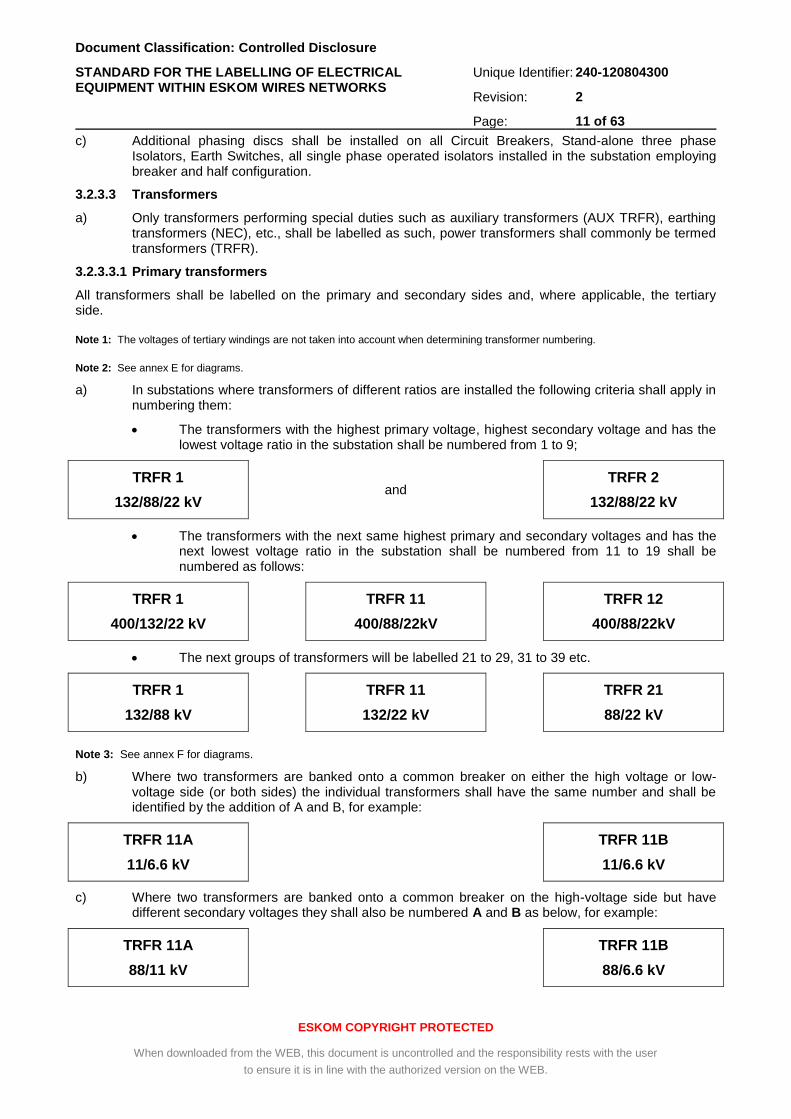
a) In substations where transformers of different ratios are installed the following criteria shall apply in numbering them:
The transformers with the highest primary voltage, highest secondary voltage and has the lowest voltage ratio in the substation shall be numbered from 1 to 9;
TRFR 1
132/88/22 kV
and
TRFR 2
132/88/22 kV
The transformers with the next same highest primary and secondary voltages and has the next lowest voltage ratio in the substation shall be numbered from 11 to 19 shall be numbered as follows:
TRFR 1
400/132/22 kV
TRFR 11
400/88/22kV
TRFR 12
400/88/22kV
The next groups of transformers will be labelled 21 to 29, 31 to 39 etc.
TRFR 1
132/88 kV
TRFR 11
132/22 kV
TRFR 21
88/22 kV
Note 3: See annex F for diagrams.
b) Where two transformers are banked onto a common breaker on either the high voltage or low-voltage side (or both sides) the individual transformers shall have the same number and shall be identified by the addition of A and B, for example:
TRFR 11A
11/6.6 kV
TRFR 11B
11/6.6 kV
c) Where two transformers are banked onto a common breaker on the high-voltage side but have different secondary voltages they shall also be numbered A and B as below, for example:
TRFR 11A
88/11 kV
TRFR 11B
88/6.6 kV
Document Classification: Controlled Disclosure
STANDARD FOR THE LABELLING OF ELECTRICAL EQUIPMENT WITHIN ESKOM WIRES NETWORKS
Unique Identifier: 240-120804300
Revision: 2
Page: 12 of 63
ESKOM COPYRIGHT PROTECTED
When downloaded from the WEB, this document is uncontrolled and the responsibility rests with the user
to ensure it is in line with the authorized version on the WEB.
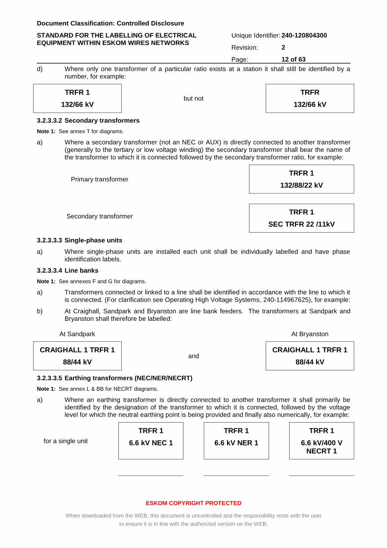
d) Where only one transformer of a particular ratio exists at a station it shall still be identified by a number, for example:
TRFR 1
132/66 kV
but not
TRFR
132/66 kV
3.2.3.3.2 Secondary transformers
Note 1: See annex T for diagrams.
a) Where a secondary transformer (not an NEC or AUX) is directly connected to another transformer (generally to the tertiary or low voltage winding) the secondary transformer shall bear the name of the transformer to which it is connected followed by the secondary transformer ratio, for example:
Primary transformer
TRFR 1
132/88/22 kV
Secondary transformer TRFR 1
SEC TRFR 22 /11kV
3.2.3.3.3 Single-phase units
a) Where single-phase units are installed each unit shall be individually labelled and have phase identification labels.
3.2.3.3.4 Line banks
Note 1: See annexes F and G for diagrams.
a) Transformers connected or linked to a line shall be identified in accordance with the line to which it is connected. (For clarification see Operating High Voltage Systems, 240-114967625), for example:
b) At Craighall, Sandpark and Bryanston are line bank feeders. The transformers at Sandpark and Bryanston shall therefore be labelled:
At Sandpark At Bryanston
CRAIGHALL 1 TRFR 1
88/44 kV
and
CRAIGHALL 1 TRFR 1
88/44 kV
3.2.3.3.5 Earthing transformers (NEC/NER/NECRT)
Note 1: See annex L & BB for NECRT diagrams.
a) Where an earthing transformer is directly connected to another transformer it shall primarily be identified by the designation of the transformer to which it is connected, followed by the voltage level for which the neutral earthing point is being provided and finally also numerically, for example:
for a single unit
TRFR 1
6.6 kV NEC 1
TRFR 1
6.6 kV NER 1
TRFR 1
6.6 kV/400 V NECRT 1
Document Classification: Controlled Disclosure
STANDARD FOR THE LABELLING OF ELECTRICAL EQUIPMENT WITHIN ESKOM WIRES NETWORKS
Unique Identifier: 240-120804300
Revision: 2
Page: 13 of 63
ESKOM COPYRIGHT PROTECTED
When downloaded from the WEB, this document is uncontrolled and the responsibility rests with the user
to ensure it is in line with the authorized version on the WEB.
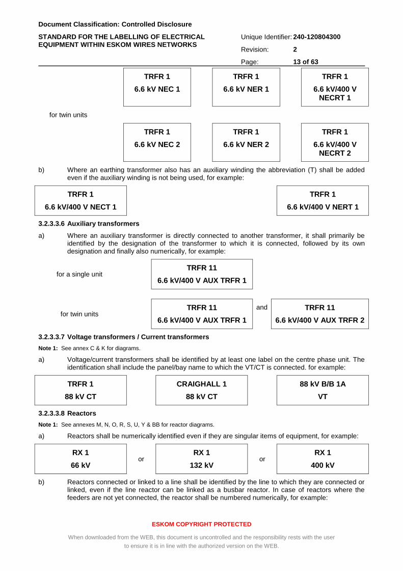
for twin units
TRFR 1
6.6 kV NEC 1
TRFR 1
6.6 kV NER 1
TRFR 1
6.6 kV/400 V NECRT 1
TRFR 1
6.6 kV NEC 2
TRFR 1
6.6 kV NER 2
TRFR 1
6.6 kV/400 V NECRT 2
b) Where an earthing transformer also has an auxiliary winding the abbreviation (T) shall be added even if the auxiliary winding is not being used, for example:
TRFR 1
6.6 kV/400 V NECT 1
TRFR 1
6.6 kV/400 V NERT 1
3.2.3.3.6 Auxiliary transformers
a) Where an auxiliary transformer is directly connected to another transformer, it shall primarily be identified by the designation of the transformer to which it is connected, followed by its own designation and finally also numerically, for example:
for a single unit TRFR 11
6.6 kV/400 V AUX TRFR 1
for twin units TRFR 11
6.6 kV/400 V AUX TRFR 1
and TRFR 11
6.6 kV/400 V AUX TRFR 2
3.2.3.3.7 Voltage transformers / Current transformers
Note 1: See annex C & K for diagrams.
a) Voltage/current transformers shall be identified by at least one label on the centre phase unit. The identification shall include the panel/bay name to which the VT/CT is connected. for example:
TRFR 1
88 kV CT
CRAIGHALL 1
88 kV CT
88 kV B/B 1A
VT
3.2.3.3.8 Reactors
Note 1: See annexes M, N, O, R, S, U, Y & BB for reactor diagrams.
a) Reactors shall be numerically identified even if they are singular items of equipment, for example:
RX 1
66 kV or
RX 1
132 kV or
RX 1
400 kV
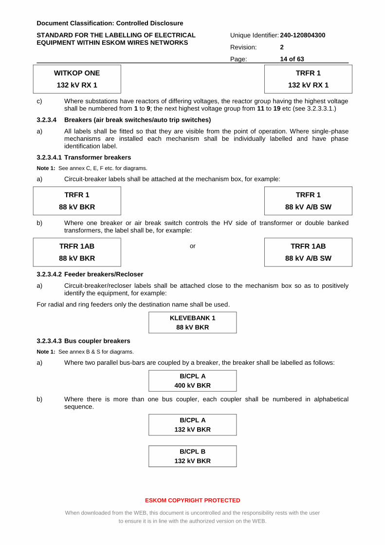
b) Reactors connected or linked to a line shall be identified by the line to which they are connected or linked, even if the line reactor can be linked as a busbar reactor. In case of reactors where the feeders are not yet connected, the reactor shall be numbered numerically, for example:
Document Classification: Controlled Disclosure
STANDARD FOR THE LABELLING OF ELECTRICAL EQUIPMENT WITHIN ESKOM WIRES NETWORKS
Unique Identifier: 240-120804300
Revision: 2
Page: 14 of 63
ESKOM COPYRIGHT PROTECTED
When downloaded from the WEB, this document is uncontrolled and the responsibility rests with the user
to ensure it is in line with the authorized version on the WEB.
WITKOP ONE
132 kV RX 1
TRFR 1
132 kV RX 1
c) Where substations have reactors of differing voltages, the reactor group having the highest voltage shall be numbered from 1 to 9; the next highest voltage group from 11 to 19 etc (see 3.2.3.3.1.)
3.2.3.4 Breakers (air break switches/auto trip switches)
a) All labels shall be fitted so that they are visible from the point of operation. Where single-phase mechanisms are installed each mechanism shall be individually labelled and have phase identification label.
3.2.3.4.1 Transformer breakers
Note 1: See annex C, E, F etc. for diagrams.
a) Circuit-breaker labels shall be attached at the mechanism box, for example:
TRFR 1
88 kV BKR
TRFR 1
88 kV A/B SW
b) Where one breaker or air break switch controls the HV side of transformer or double banked transformers, the label shall be, for example:
TRFR 1AB
88 kV BKR
or TRFR 1AB
88 kV A/B SW
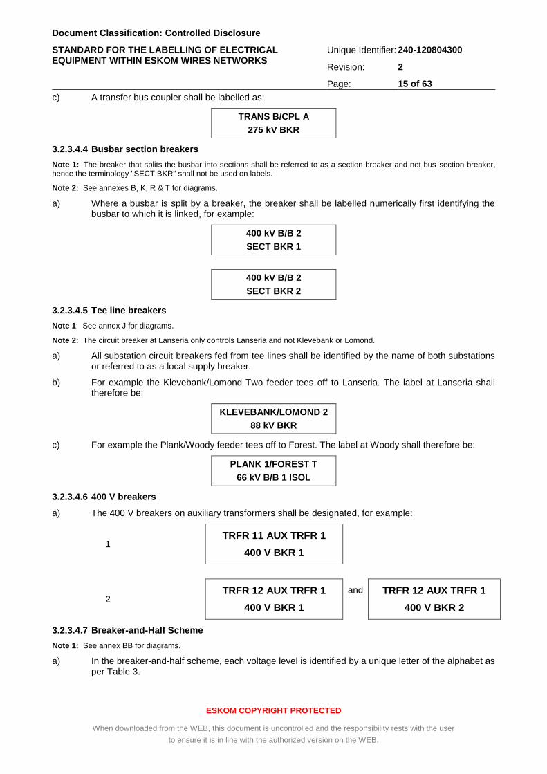
3.2.3.4.2 Feeder breakers/Recloser
a) Circuit-breaker/recloser labels shall be attached close to the mechanism box so as to positively identify the equipment, for example:
For radial and ring feeders only the destination name shall be used.
KLEVEBANK 1
88 kV BKR
3.2.3.4.3 Bus coupler breakers
Note 1: See annex B & S for diagrams.
a) Where two parallel bus-bars are coupled by a breaker, the breaker shall be labelled as follows:
B/CPL A
400 kV BKR
b) Where there is more than one bus coupler, each coupler shall be numbered in alphabetical sequence.
B/CPL A
132 kV BKR
B/CPL B
132 kV BKR
Document Classification: Controlled Disclosure
STANDARD FOR THE LABELLING OF ELECTRICAL EQUIPMENT WITHIN ESKOM WIRES NETWORKS
Unique Identifier: 240-120804300
Revision: 2
Page: 15 of 63
ESKOM COPYRIGHT PROTECTED
When downloaded from the WEB, this document is uncontrolled and the responsibility rests with the user
to ensure it is in line with the authorized version on the WEB.
c) A transfer bus coupler shall be labelled as:
TRANS B/CPL A
275 kV BKR
3.2.3.4.4 Busbar section breakers
Note 1: The breaker that splits the busbar into sections shall be referred to as a section breaker and not bus section breaker, hence the terminology "SECT BKR" shall not be used on labels.
Note 2: See annexes B, K, R & T for diagrams.
a) Where a busbar is split by a breaker, the breaker shall be labelled numerically first identifying the busbar to which it is linked, for example:
400 kV B/B 2
SECT BKR 1
400 kV B/B 2
SECT BKR 2
3.2.3.4.5 Tee line breakers
Note 1: See annex J for diagrams.
Note 2: The circuit breaker at Lanseria only controls Lanseria and not Klevebank or Lomond.
a) All substation circuit breakers fed from tee lines shall be identified by the name of both substations or referred to as a local supply breaker.
b) For example the Klevebank/Lomond Two feeder tees off to Lanseria. The label at Lanseria shall therefore be:
KLEVEBANK/LOMOND 2
88 kV BKR
c) For example the Plank/Woody feeder tees off to Forest. The label at Woody shall therefore be:
PLANK 1/FOREST T
66 kV B/B 1 ISOL
3.2.3.4.6 400 V breakers
a) The 400 V breakers on auxiliary transformers shall be designated, for example:
1 TRFR 11 AUX TRFR 1
400 V BKR 1
2 TRFR 12 AUX TRFR 1
400 V BKR 1
and TRFR 12 AUX TRFR 1
400 V BKR 2
3.2.3.4.7 Breaker-and-Half Scheme
Note 1: See annex BB for diagrams.
a) In the breaker-and-half scheme, each voltage level is identified by a unique letter of the alphabet as per Table 3.
Document Classification: Controlled Disclosure
STANDARD FOR THE LABELLING OF ELECTRICAL EQUIPMENT WITHIN ESKOM WIRES NETWORKS
Unique Identifier: 240-120804300
Revision: 2
Page: 16 of 63
ESKOM COPYRIGHT PROTECTED
When downloaded from the WEB, this document is uncontrolled and the responsibility rests with the user
to ensure it is in line with the authorized version on the WEB.
b) Each diameter will be named alphabetically instead of numerically. For example; the first 765 kV diameter will be named MA (M for the voltage level and A to identify it as the first diameter. (A diameter is the connection of two parallel busbars connected together by two or three circuit breakers.)
c) A typical example of the breaker-and-half scheme is detailed in Annexure BB.
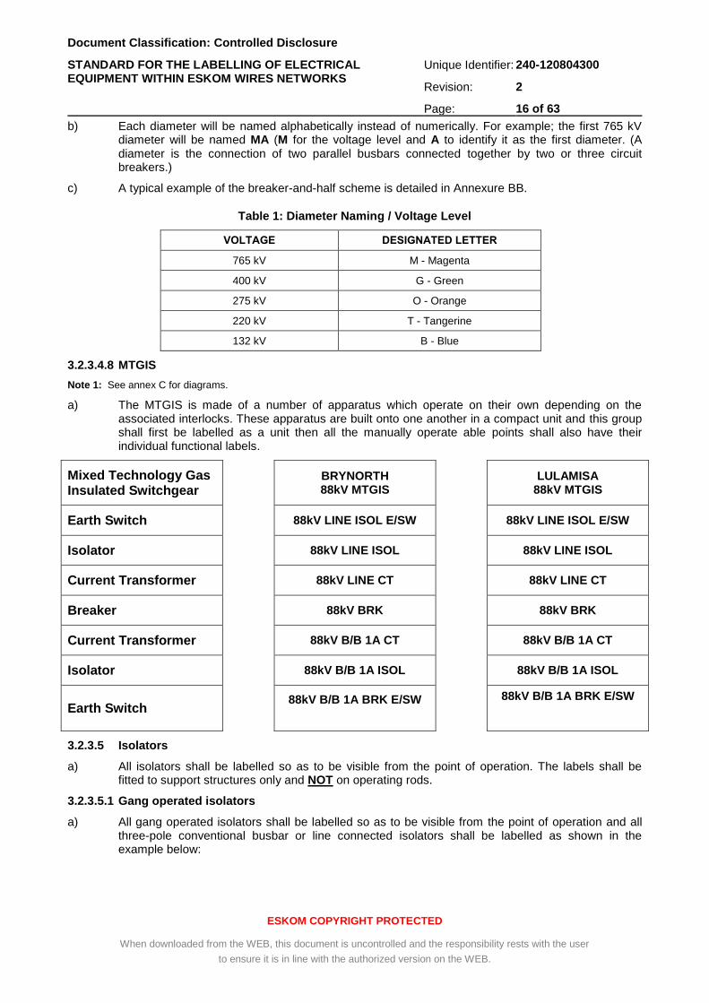
Table 1: Diameter Naming / Voltage Level
VOLTAGE DESIGNATED LETTER
765 kV M - Magenta
400 kV G - Green
275 kV O - Orange
220 kV T - Tangerine
132 kV B - Blue
3.2.3.4.8 MTGIS
Note 1: See annex C for diagrams.
a) The MTGIS is made of a number of apparatus which operate on their own depending on the associated interlocks. These apparatus are built onto one another in a compact unit and this group shall first be labelled as a unit then all the manually operate able points shall also have their individual functional labels.
Mixed Technology Gas Insulated Switchgear
BRYNORTH 88kV MTGIS
LULAMISA 88kV MTGIS
Earth Switch 88kV LINE ISOL E/SW 88kV LINE ISOL E/SW
Isolator 88kV LINE ISOL 88kV LINE ISOL
Current Transformer 88kV LINE CT 88kV LINE CT
Breaker 88kV BRK 88kV BRK
Current Transformer 88kV B/B 1A CT 88kV B/B 1A CT
Isolator 88kV B/B 1A ISOL 88kV B/B 1A ISOL
Earth Switch 88kV B/B 1A BRK E/SW
88kV B/B 1A BRK E/SW
3.2.3.5 Isolators
a) All isolators shall be labelled so as to be visible from the point of operation. The labels shall be fitted to support structures only and NOT on operating rods.
3.2.3.5.1 Gang operated isolators
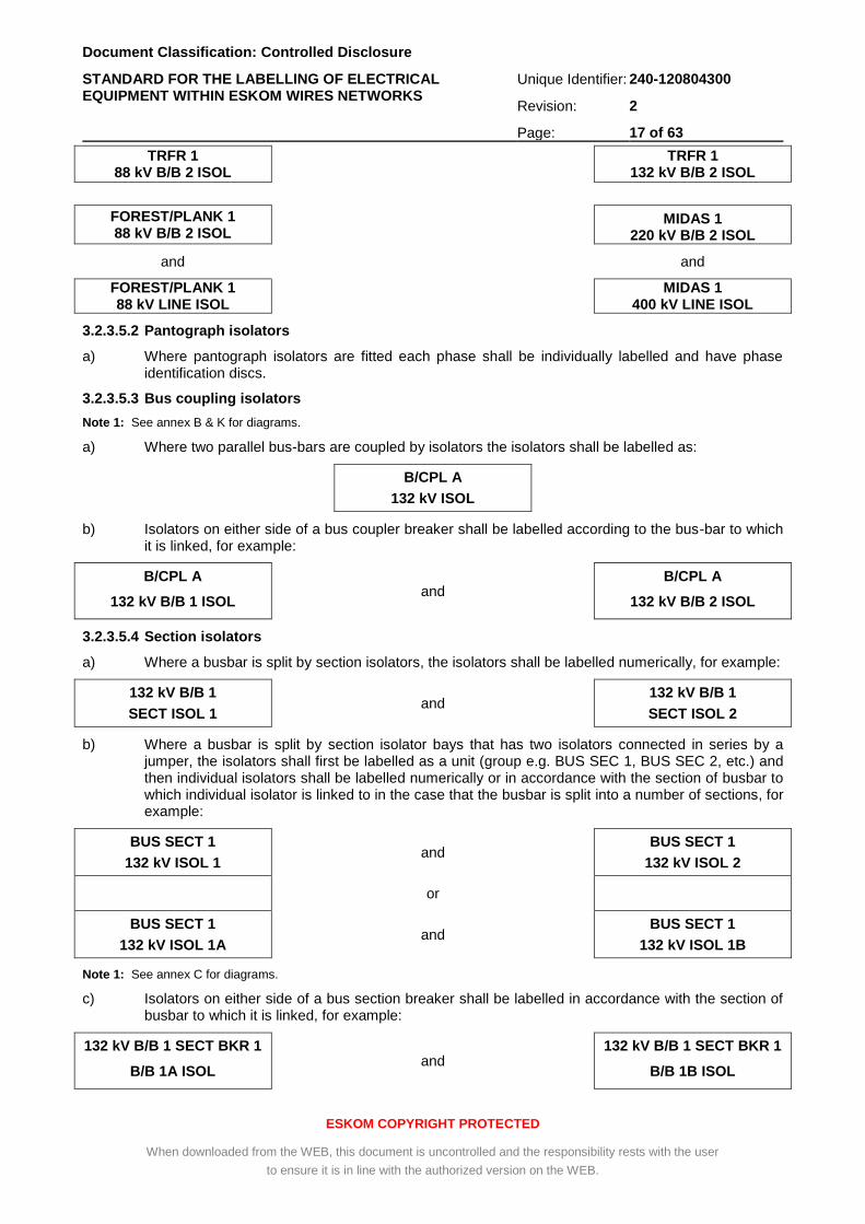
a) All gang operated isolators shall be labelled so as to be visible from the point of operation and all three-pole conventional busbar or line connected isolators shall be labelled as shown in the example below:
Document Classification: Controlled Disclosure
STANDARD FOR THE LABELLING OF ELECTRICAL EQUIPMENT WITHIN ESKOM WIRES NETWORKS
Unique Identifier: 240-120804300
Revision: 2
Page: 17 of 63
ESKOM COPYRIGHT PROTECTED
When downloaded from the WEB, this document is uncontrolled and the responsibility rests with the user
to ensure it is in line with the authorized version on the WEB.
TRFR 1 88 kV B/B 2 ISOL
TRFR 1
132 kV B/B 2 ISOL
FOREST/PLANK 1 88 kV B/B 2 ISOL
MIDAS 1 220 kV B/B 2 ISOL
and and
FOREST/PLANK 1
88 kV LINE ISOL MIDAS 1
400 kV LINE ISOL
3.2.3.5.2 Pantograph isolators
a) Where pantograph isolators are fitted each phase shall be individually labelled and have phase identification discs.
3.2.3.5.3 Bus coupling isolators
Note 1: See annex B & K for diagrams.
a) Where two parallel bus-bars are coupled by isolators the isolators shall be labelled as:
B/CPL A
132 kV ISOL
b) Isolators on either side of a bus coupler breaker shall be labelled according to the bus-bar to which it is linked, for example:
B/CPL A
132 kV B/B 1 ISOL
and
B/CPL A
132 kV B/B 2 ISOL
3.2.3.5.4 Section isolators
a) Where a busbar is split by section isolators, the isolators shall be labelled numerically, for example:
132 kV B/B 1
SECT ISOL 1 and 132 kV B/B 1
SECT ISOL 2
b) Where a busbar is split by section isolator bays that has two isolators connected in series by a jumper, the isolators shall first be labelled as a unit (group e.g. BUS SEC 1, BUS SEC 2, etc.) and then individual isolators shall be labelled numerically or in accordance with the section of busbar to which individual isolator is linked to in the case that the busbar is split into a number of sections, for example:
BUS SECT 1
132 kV ISOL 1 and BUS SECT 1
132 kV ISOL 2
or
BUS SECT 1
132 kV ISOL 1A and BUS SECT 1
132 kV ISOL 1B
Note 1: See annex C for diagrams.
c) Isolators on either side of a bus section breaker shall be labelled in accordance with the section of busbar to which it is linked, for example:
132 kV B/B 1 SECT BKR 1
B/B 1A ISOL and
132 kV B/B 1 SECT BKR 1
B/B 1B ISOL
Document Classification: Controlled Disclosure
STANDARD FOR THE LABELLING OF ELECTRICAL EQUIPMENT WITHIN ESKOM WIRES NETWORKS
Unique Identifier: 240-120804300
Revision: 2
Page: 18 of 63
ESKOM COPYRIGHT PROTECTED
When downloaded from the WEB, this document is uncontrolled and the responsibility rests with the user
to ensure it is in line with the authorized version on the WEB.
Note 1: The isolator that splits the busbar into sections shall be referred to as a section isolator and not bus section isolator, hence the terminology "B/SECT ISOL" shall not be used on labels (see Annex C).
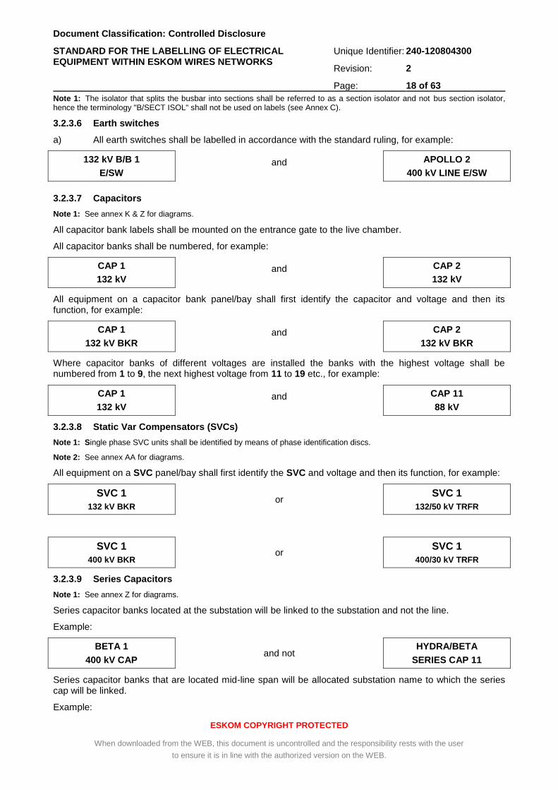
3.2.3.6 Earth switches
a) All earth switches shall be labelled in accordance with the standard ruling, for example:
132 kV B/B 1
E/SW and APOLLO 2
400 kV LINE E/SW
3.2.3.7 Capacitors
Note 1: See annex K & Z for diagrams.
All capacitor bank labels shall be mounted on the entrance gate to the live chamber.
All capacitor banks shall be numbered, for example:
CAP 1
132 kV and CAP 2
132 kV
All equipment on a capacitor bank panel/bay shall first identify the capacitor and voltage and then its function, for example:
CAP 1
132 kV BKR and CAP 2
132 kV BKR
Where capacitor banks of different voltages are installed the banks with the highest voltage shall be numbered from 1 to 9, the next highest voltage from 11 to 19 etc., for example:
CAP 1
132 kV and CAP 11
88 kV
3.2.3.8 Static Var Compensators (SVCs)
Note 1: Single phase SVC units shall be identified by means of phase identification discs.
Note 2: See annex AA for diagrams.
All equipment on a SVC panel/bay shall first identify the SVC and voltage and then its function, for example:
SVC 1
132 kV BKR or
SVC 1
132/50 kV TRFR
SVC 1
400 kV BKR or
SVC 1
400/30 kV TRFR
3.2.3.9 Series Capacitors
Note 1: See annex Z for diagrams.
Series capacitor banks located at the substation will be linked to the substation and not the line.
Example:
BETA 1
400 kV CAP and not
HYDRA/BETA
SERIES CAP 11
Series capacitor banks that are located mid-line span will be allocated substation name to which the series cap will be linked.
Example:
Document Classification: Controlled Disclosure
STANDARD FOR THE LABELLING OF ELECTRICAL EQUIPMENT WITHIN ESKOM WIRES NETWORKS
Unique Identifier: 240-120804300
Revision: 2
Page: 19 of 63
ESKOM COPYRIGHT PROTECTED
When downloaded from the WEB, this document is uncontrolled and the responsibility rests with the user
to ensure it is in line with the authorized version on the WEB.
KOMSBERG CAP 11
400 kV BYPASS BKR and not
HYDRA/BETA CAP 11
400 kV BYPASS BKR
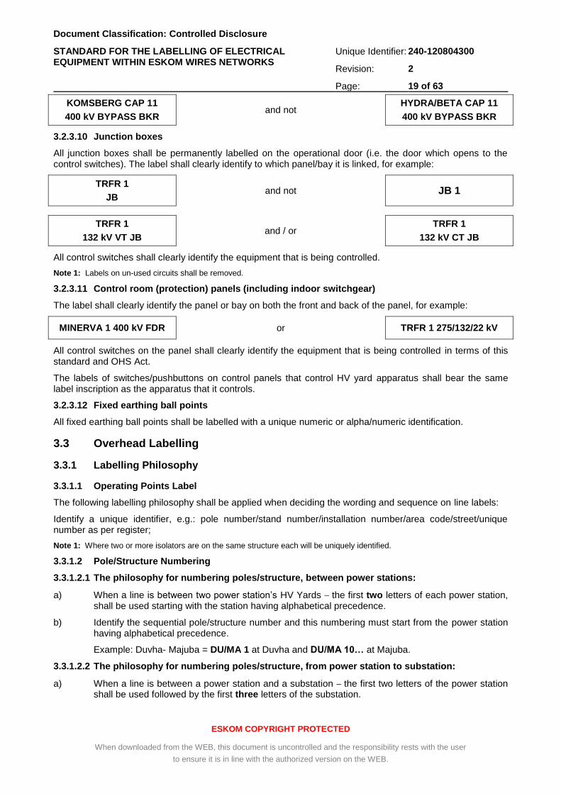
3.2.3.10 Junction boxes
All junction boxes shall be permanently labelled on the operational door (i.e. the door which opens to the control switches). The label shall clearly identify to which panel/bay it is linked, for example:
TRFR 1
JB and not JB 1
TRFR 1
132 kV VT JB and / or
TRFR 1
132 kV CT JB
All control switches shall clearly identify the equipment that is being controlled.
Note 1: Labels on un-used circuits shall be removed.
3.2.3.11 Control room (protection) panels (including indoor switchgear)
The label shall clearly identify the panel or bay on both the front and back of the panel, for example:
MINERVA 1 400 kV FDR or TRFR 1 275/132/22 kV
All control switches on the panel shall clearly identify the equipment that is being controlled in terms of this standard and OHS Act.
The labels of switches/pushbuttons on control panels that control HV yard apparatus shall bear the same label inscription as the apparatus that it controls.
3.2.3.12 Fixed earthing ball points
All fixed earthing ball points shall be labelled with a unique numeric or alpha/numeric identification.
3.3 Overhead Labelling
3.3.1 Labelling Philosophy
3.3.1.1 Operating Points Label
The following labelling philosophy shall be applied when deciding the wording and sequence on line labels:
Identify a unique identifier, e.g.: pole number/stand number/installation number/area code/street/unique number as per register;
Note 1: Where two or more isolators are on the same structure each will be uniquely identified.
3.3.1.2 Pole/Structure Numbering
3.3.1.2.1 The philosophy for numbering poles/structure, between power stations:
a) When a line is between two power station’s HV Yards the first two letters of each power station, shall be used starting with the station having alphabetical precedence.
b) Identify the sequential pole/structure number and this numbering must start from the power station having alphabetical precedence.
Example: Duvha- Majuba = DU/MA 1 at Duvha and DU/MA 10… at Majuba.
3.3.1.2.2 The philosophy for numbering poles/structure, from power station to substation:
a) When a line is between a power station and a substation the first two letters of the power station shall be used followed by the first three letters of the substation.
Document Classification: Controlled Disclosure
STANDARD FOR THE LABELLING OF ELECTRICAL EQUIPMENT WITHIN ESKOM WIRES NETWORKS
Unique Identifier: 240-120804300
Revision: 2
Page: 20 of 63
ESKOM COPYRIGHT PROTECTED
When downloaded from the WEB, this document is uncontrolled and the responsibility rests with the user
to ensure it is in line with the authorized version on the WEB.
b) Identify the sequential pole/structure number and this numbering must start from the source power station.
Example: Majuba- Klaarwater = MA/KLA 1 at Majuba and MA/KLA 30… at Klaarwater.
Note 1: Between a power station and a substation where a line forms a connection between a power station and a substation the name of the power station shall appear first.
3.3.1.2.3 The philosophy for numbering poles/structure, from substation to substation:
a) Firstly identify the number of the line.
b) Secondly identify the source and destination alphabetically and the first three letters of each substation shall be used starting with the substation having alphabetical precedence. In the case where names like “Port Shepstone” and “Port Edward” are substation names in question:_ where the first term of the two terms in the substation names is the same, an exception can be made whereby the first letter in the first term and the first two letters in the second term should be used ie. PSH and PED.
c) Thirdly identify the sequential pole/structure number and this numbering must start from the source substation;
Example: Sol- Zeus = SOL/ZEU 1 at Sol and SOL/ZEU 50… at Zeus.
Note 1: The reason for putting the line number first on the label is to prevent it from being interpreted as part of the pole/structure number, e.g. 2 KLE/LOM 2 and not KLE/LOM 2 2. The label is still interpreted as KLEVELAND/LOMOND line two, tower two.
Note 2: Due to Data Capture System (Smallworld) the length of the number on labels must be restricted to a maximum of 60 characters.
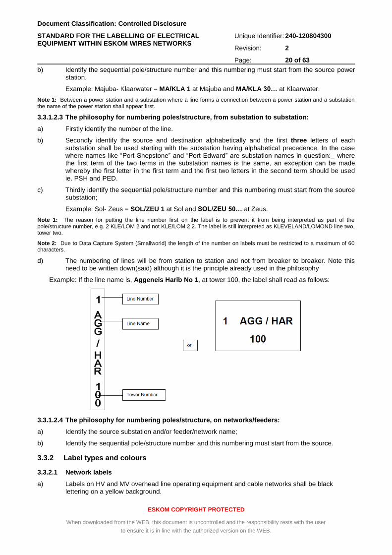
d) The numbering of lines will be from station to station and not from breaker to breaker. Note this need to be written down(said) although it is the principle already used in the philosophy
Example: If the line name is, Aggeneis Harib No 1, at tower 100, the label shall read as follows:
3.3.1.2.4 The philosophy for numbering poles/structure, on networks/feeders:
a) Identify the source substation and/or feeder/network name;
b) Identify the sequential pole/structure number and this numbering must start from the source.
3.3.2 Label types and colours
3.3.2.1 Network labels
a) Labels on HV and MV overhead line operating equipment and cable networks shall be black lettering on a yellow background.
Document Classification: Controlled Disclosure
STANDARD FOR THE LABELLING OF ELECTRICAL EQUIPMENT WITHIN ESKOM WIRES NETWORKS
Unique Identifier: 240-120804300
Revision: 2
Page: 21 of 63
ESKOM COPYRIGHT PROTECTED
When downloaded from the WEB, this document is uncontrolled and the responsibility rests with the user
to ensure it is in line with the authorized version on the WEB.
b) Labels on LV operating equipment shall be black lettering on a white background.
Note 1: Orange background shall only be used in the substations.
3.3.2.2 Line Crossing Labels
a) Line crossing labels shall be a black cross on a reflective background. Refer to 240-75660336.
3.3.3 Overhead Lines Labels
All towers and poles shall be labelled with a unique tower/pole identification number. All terminal towers, tee-off terminal towers and phase transposition shall have phase discs fitted.
Note 1: See annexes P & U for diagrams.
3.3.3.1 HV Tower/Pole Identification Label
a) On towers, a single label that is visible from ground level as well as from a helicopter during an aerial line inspection shall be mounted at the waist of the tower.
b) The single pole structure label shall be installed above five meters from the ground.
c) The designation of a line shall be an abbreviation of the power station names, substation names and network / feeder names. The abbreviations used shall comply with the philosophies in section 3.1.6. above.
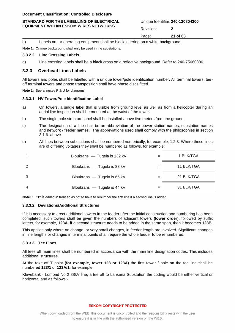
d) All lines between substations shall be numbered numerically, for example, 1,2,3. Where these lines are of differing voltages they shall be numbered as follows, for example:
1 Bloukrans Tugela is 132 kV = 1 BLK/TGA
2 Bloukrans Tugela is 88 kV = 11 BLK/TGA
3 Bloukrans Tugela is 66 kV = 21 BLK/TGA
4 Bloukrans Tugela is 44 kV = 31 BLK/TGA
Note1: “1” is added in front so as not to have to renumber the first line if a second line is added.
3.3.3.2 Deviations/Additional Structures
If it is necessary to erect additional towers in the feeder after the initial construction and numbering has been completed, such towers shall be given the numbers of adjacent towers (lower order), followed by suffix letters, for example, 123A, if a second structure needs to be added in the same span, then it becomes 123B.
This applies only where no change, or very small changes, in feeder length are involved. Significant changes in line lengths or changes in terminal points shall require the whole feeder to be renumbered.
3.3.3.3 Tee Lines
All tees off main lines shall be numbered in accordance with the main line designation codes. This includes additional structures.
At the take-off T point (for example, tower 123 or 123A) the first tower / pole on the tee line shall be numbered 123/1 or 123A/1, for example:
Klevebank - Lomond No 2 88kV line, a tee off to Lanseria Substation the coding would be either vertical or horizontal and as follows:-
Document Classification: Controlled Disclosure
STANDARD FOR THE LABELLING OF ELECTRICAL EQUIPMENT WITHIN ESKOM WIRES NETWORKS
Unique Identifier: 240-120804300
Revision: 2
Page: 22 of 63
ESKOM COPYRIGHT PROTECTED
When downloaded from the WEB, this document is uncontrolled and the responsibility rests with the user
to ensure it is in line with the authorized version on the WEB.
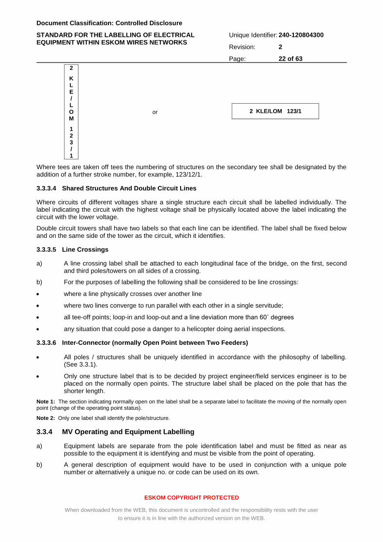
2
K L E / L O M
1 2 3 / 1
or
2 KLE/LOM 123/1
Where tees are taken off tees the numbering of structures on the secondary tee shall be designated by the addition of a further stroke number, for example, 123/12/1.
3.3.3.4 Shared Structures And Double Circuit Lines
Where circuits of different voltages share a single structure each circuit shall be labelled individually. The label indicating the circuit with the highest voltage shall be physically located above the label indicating the circuit with the lower voltage.
Double circuit towers shall have two labels so that each line can be identified. The label shall be fixed below and on the same side of the tower as the circuit, which it identifies.
3.3.3.5 Line Crossings
a) A line crossing label shall be attached to each longitudinal face of the bridge, on the first, second and third poles/towers on all sides of a crossing.
b) For the purposes of labelling the following shall be considered to be line crossings:
where a line physically crosses over another line
where two lines converge to run parallel with each other in a single servitude;
all tee-off points; loop-in and loop-out and a line deviation more than 60˚ degrees
any situation that could pose a danger to a helicopter doing aerial inspections.
3.3.3.6 Inter-Connector (normally Open Point between Two Feeders)
All poles / structures shall be uniquely identified in accordance with the philosophy of labelling. (See 3.3.1).
Only one structure label that is to be decided by project engineer/field services engineer is to be placed on the normally open points. The structure label shall be placed on the pole that has the shorter length.
Note 1: The section indicating normally open on the label shall be a separate label to facilitate the moving of the normally open point (change of the operating point status).
Note 2: Only one label shall identify the pole/structure.
3.3.4 MV Operating and Equipment Labelling
a) Equipment labels are separate from the pole identification label and must be fitted as near as possible to the equipment it is identifying and must be visible from the point of operating.
b) A general description of equipment would have to be used in conjunction with a unique pole number or alternatively a unique no. or code can be used on its own.
Document Classification: Controlled Disclosure
STANDARD FOR THE LABELLING OF ELECTRICAL EQUIPMENT WITHIN ESKOM WIRES NETWORKS
Unique Identifier: 240-120804300
Revision: 2
Page: 23 of 63
ESKOM COPYRIGHT PROTECTED
When downloaded from the WEB, this document is uncontrolled and the responsibility rests with the user
to ensure it is in line with the authorized version on the WEB.
3.3.4.1 MV Pole / structure identification Labels
All poles / structures shall be uniquely identified in accordance with the philosophy of labelling. (See 3.3.1).
All labels shall be alpha numeric. The alpha digits denote the substation and feeder / network name. The numeric digits denote the pole number.
Multiple pole structures are to be considered as a single pole and given one pole number only.
Where LV and MV are on a common pole / structure the MV label is used. However where it can assist in the identification of LV circuits and / or customers a separate LV label can also be affixed.
Where operating equipment is mounted on a pole / structure the equipment label is in addition to the pole / structure identification.
Note 1: The label layout and label colour shall conform to network philosophy, see 3.3.1. & 3.3.2.
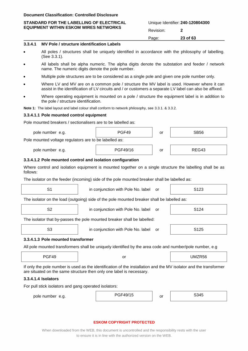
3.3.4.1.1 Pole mounted control equipment
Pole mounted breakers / sectionalisers are to be labelled as:
pole number e.g. PGF49 or SB56
Pole mounted voltage regulators are to be labelled as:
pole number e.g. PGF49/16 or REG43
3.3.4.1.2 Pole mounted control and isolation configuration
Where control and isolation equipment is mounted together on a single structure the labelling shall be as follows:
The isolator on the feeder (incoming) side of the pole mounted breaker shall be labelled as:
S1 in conjunction with Pole No. label or S123
The isolator on the load (outgoing) side of the pole mounted breaker shall be labelled as:
S2 in conjunction with Pole No. label or S124
The isolator that by-passes the pole mounted breaker shall be labelled:
S3 in conjunction with Pole No. label or S125
3.3.4.1.3 Pole mounted transformer
All pole mounted transformers shall be uniquely identified by the area code and number/pole number, e.g
PGF49 or UMZR56
If only the pole number is used as the identification of the installation and the MV isolator and the transformer are situated on the same structure then only one label is necessary.
3.3.4.1.4 Isolators
For pull stick isolators and gang operated isolators:
pole number e.g. PGF49/15 or S345
Document Classification: Controlled Disclosure
STANDARD FOR THE LABELLING OF ELECTRICAL EQUIPMENT WITHIN ESKOM WIRES NETWORKS
Unique Identifier: 240-120804300
Revision: 2
Page: 24 of 63
ESKOM COPYRIGHT PROTECTED
When downloaded from the WEB, this document is uncontrolled and the responsibility rests with the user
to ensure it is in line with the authorized version on the WEB.
For drop out fuse isolators:
pole number e.g. PGF49/16/13 or T123L1
3.3.5 LV Operating point labelling
3.3.5.1 LV Pole/structure identification Labels
a) All LV poles / structures are to be identified in accordance with the MV numbering system.
b) Where multiple LV feeders are fed from a single source the individual feeders shall be identified by the addition of A or B or C to the end of the pole identification number.
Note 1: All Operating point labels shall be fitted as near as possible to the equipment it is identifying and must be visible from the point of operating.
c) The LV equipment shall be labelled as follows:
Isolators
All isolators shall be uniquely labelled.
Fuses
Fuses shall be uniquely labelled and indicate the current rating.
Circuit Breakers
Where customers are fed directly via a circuit breaker each circuit breaker (pole top make-off) shall be uniquely labelled A, B, C, etc.
3.4 Cable Underground Systems Labelling
3.4.1 MV Labelling Philosophy
3.4.1.1 Mini-Sub and RMU
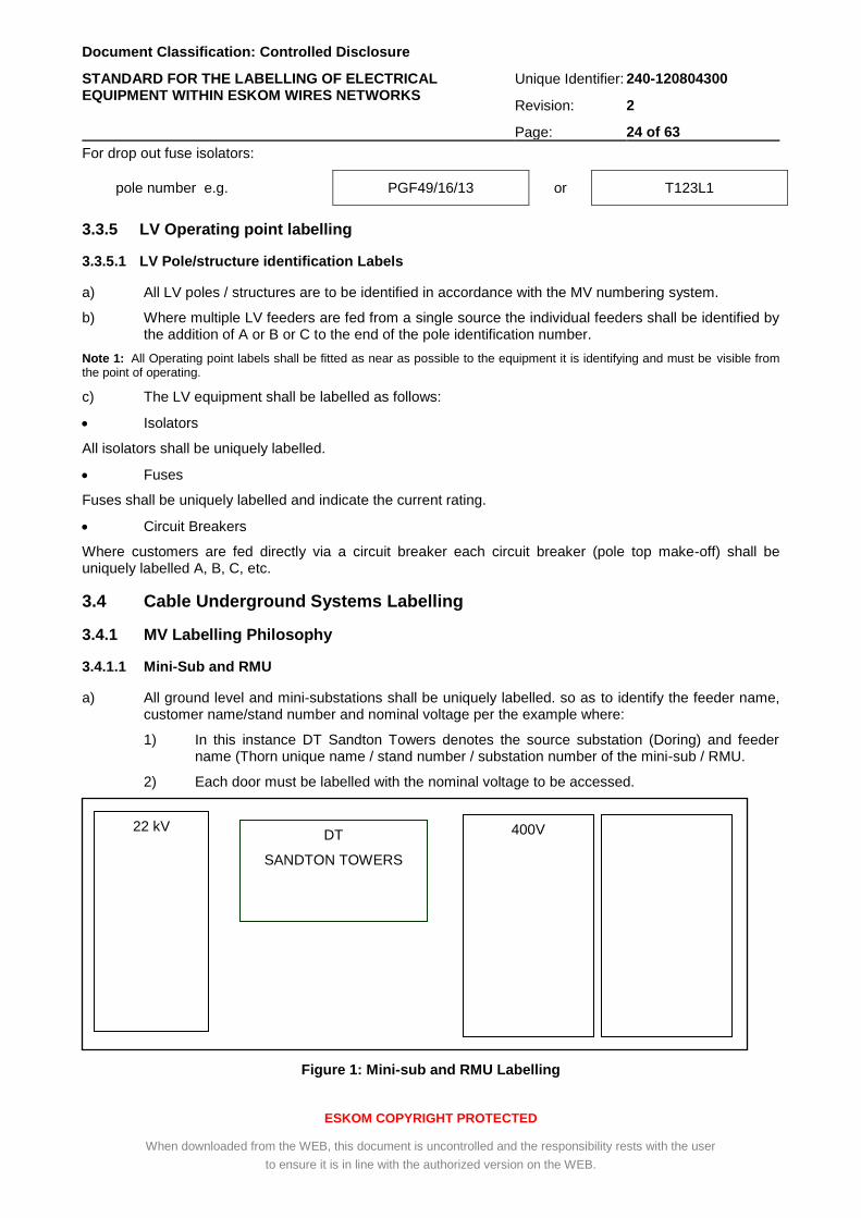
a) All ground level and mini-substations shall be uniquely labelled. so as to identify the feeder name, customer name/stand number and nominal voltage per the example where:
1) In this instance DT Sandton Towers denotes the source substation (Doring) and feeder name (Thorn unique name / stand number / substation number of the mini-sub / RMU.
2) Each door must be labelled with the nominal voltage to be accessed.
Figure 1: Mini-sub and RMU Labelling
22 kV 400V DT
SANDTON TOWERS
Document Classification: Controlled Disclosure
STANDARD FOR THE LABELLING OF ELECTRICAL EQUIPMENT WITHIN ESKOM WIRES NETWORKS
Unique Identifier: 240-120804300
Revision: 2
Page: 25 of 63
ESKOM COPYRIGHT PROTECTED
When downloaded from the WEB, this document is uncontrolled and the responsibility rests with the user
to ensure it is in line with the authorized version on the WEB.
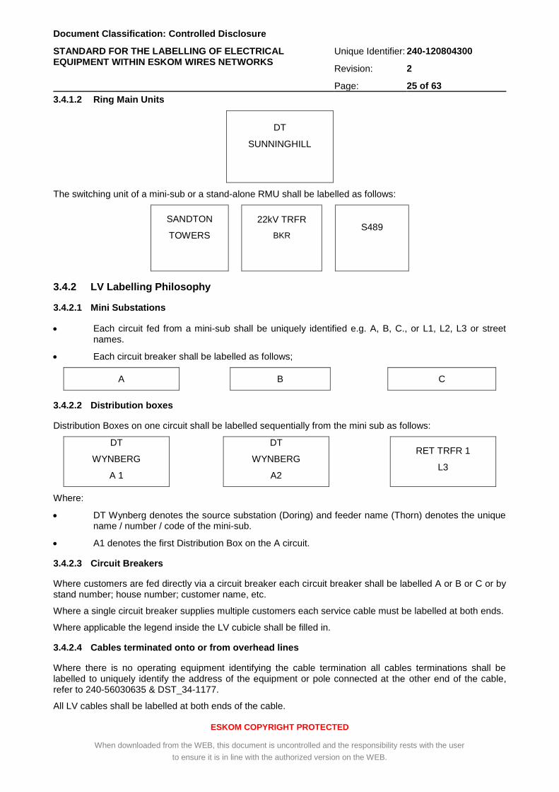
3.4.1.2 Ring Main Units
DT
SUNNINGHILL
The switching unit of a mini-sub or a stand-alone RMU shall be labelled as follows:
SANDTON
TOWERS
22kV TRFR
BKR
S489
3.4.2 LV Labelling Philosophy
3.4.2.1 Mini Substations
Each circuit fed from a mini-sub shall be uniquely identified e.g. A, B, C., or L1, L2, L3 or street names.
Each circuit breaker shall be labelled as follows;
A B C
3.4.2.2 Distribution boxes
Distribution Boxes on one circuit shall be labelled sequentially from the mini sub as follows:
DT
WYNBERG
A 1
DT
WYNBERG
A2
RET TRFR 1
L3
Where:
DT Wynberg denotes the source substation (Doring) and feeder name (Thorn) denotes the unique name / number / code of the mini-sub.
A1 denotes the first Distribution Box on the A circuit.
3.4.2.3 Circuit Breakers
Where customers are fed directly via a circuit breaker each circuit breaker shall be labelled A or B or C or by stand number; house number; customer name, etc.
Where a single circuit breaker supplies multiple customers each service cable must be labelled at both ends.
Where applicable the legend inside the LV cubicle shall be filled in.
3.4.2.4 Cables terminated onto or from overhead lines
Where there is no operating equipment identifying the cable termination all cables terminations shall be labelled to uniquely identify the address of the equipment or pole connected at the other end of the cable, refer to 240-56030635 & DST_34-1177.
All LV cables shall be labelled at both ends of the cable.
Document Classification: Controlled Disclosure
STANDARD FOR THE LABELLING OF ELECTRICAL EQUIPMENT WITHIN ESKOM WIRES NETWORKS
Unique Identifier: 240-120804300
Revision: 2
Page: 26 of 63
ESKOM COPYRIGHT PROTECTED
When downloaded from the WEB, this document is uncontrolled and the responsibility rests with the user
to ensure it is in line with the authorized version on the WEB.
3.4.3 Cable Route Markers
The cable route marker shall be installed in the ground directly above the power cable.
Cable route markers (in accordance with D-DT-8012) shall be installed in the ground directly above MV power cables at each road / railway crossing, cable joint, and where there is a change in cable direction, refer to 240-56030635.
Note 1: It is worthwhile to determine GPS coordinates of the cable route, joints, and bends, though this is not required by the standard.
4. Installation
4.1 Position of tower labels on tower / structure / pole
a) The labels shall be fitted to the frames / brackets using the bolts, nuts and washers as specified on DRG. No. 0.54/404 or the bandit-striping on pole.
b) Nuts, bolts and washers shall be supplied by the manufacturer.
c) Nuts, bolts and metal washers must be hot-dipped galvanised.
d) The nuts must be turned to firm finger tight and then tightened with a spanner one full turn. (Over-tightening will result in damage to the vitreous enamel coating).
e) The label frames / brackets will be attached to the existing support steelwork or equipment with the bolts, nuts and washers provided. The nuts must be tightened to normal spanner tightness.
f) Labels will be positioned in accordance with the Substation Operating Diagram provided.
g) All line labels shall be positioned on the tower at a height easily viewed from both the ground and air (typically from a helicopter during aerial inspections). This height shall correspond roughly to the lowest conductor height and be near the waist in the case of lattice towers (see annex BB).
h) When positioning labels, maintenance requirements shall be considered. The label shall be positioned so that maintenance or replacement is possible without interfering with the line operation _ Annex MM shows the basic positions of the tower labels for different tower types.
i) Only one tower label will be supplied for each tower. The labels shall be positioned so that all odd numbers face the direction of the substation having alphabetical precedence and that all even numbers face the other substation (see annex BB).
4.2 Position of line crossing labels on tower
4.3 Methods of attaching labels onto towers / structures
a) All labels shall be attached to the tower using three stainless steel banded straps inserted through slots (chain links welded to 10 mm round bars attached onto the frame of the label) in the labels.
b) The label shall then be attached to a member of the tower in the specified position. The most common size of strap to be used shall be the 12,7 mm ´ 0,7 mm strap.
c) The contractor shall ensure that all straps used are tightened evenly without damaging or distorting the label. All strap buckles are stainless steel.
d) All strap buckles shall be stainless steel.
e) Care shall be taken not to damage or chip the vitreous enamel labels during transport and installation.
Document Classification: Controlled Disclosure
STANDARD FOR THE LABELLING OF ELECTRICAL EQUIPMENT WITHIN ESKOM WIRES NETWORKS
Unique Identifier: 240-120804300
Revision: 2
Page: 27 of 63
ESKOM COPYRIGHT PROTECTED
When downloaded from the WEB, this document is uncontrolled and the responsibility rests with the user
to ensure it is in line with the authorized version on the WEB.
5. Related Documents
a) 240-62629353, Specification for Panel Labelling Standard;
b) 240-75660336, The Standard for Design, Manufacturing and Installation of Eskom Wires Business Equipment Labels.
6. Forms, Records and Certificates
The manufacturer testing certificate and user’s manual (including the technical specification) shall be included in the package. An example of a certificate is given in annex A.
7. Authorization
This document has been seen and accepted by:
Name and surname Designation
Amelia Mtshali Senior Manager Power Delivery Engineering
Bheki Ntshangase Snr Manager Engineering
Riaz Vajeth Snr Manager Engineering
Colin Smith Network Operations SCOT/SC Chairperson
Archie Jaykaran Maintenance SCOT/SC Chairperson
Derik Sadler Middle Manager HV Plant
Promise Quluba Zone Manager
Braam Groenewald Chief Engineer
Andre Kotze Chief Engineer
Thinus Du Plessis Chief Engineer
8. Revisions
This revision (DST_ 240-120804300) cancels and replaces all revisions of document number DSP_ Eskasaan0 / 41-1009 / 34-1439 / 41-655.
Date Rev Compiler Remarks
Oct 2018 2 DM Ntombela Below are the changes made in this revision:
a) Added a note in section 3.2.1
“Note 1: In the Panel / Bay (i.e. Transformer bay, Feeder
bay, Section bay etc) where all or a number of apparatus are grouped or compacted in one or connected in series by the jumper in such a way that the independent / individual maintenance cannot be undertaken or the identification of individual apparatus for the purpose of labelling or operating / naming is not possible or is difficult, such apparatus shall first be identified / named as a group, ie “Isolator, Earth Switch, CT and / or breaker” in the MTGIS, Section Bay consisting of two isolators whether equipped with earth
switches or not etc.”;
b) Revised Secondary Transformer label;
c) Added MTGIS section 3.2.3.4.8 in this document;
d) Reviewed section 3.2.3.5.4 Section Isolators; and
e) Renumbered the annexures.
Document Classification: Controlled Disclosure
STANDARD FOR THE LABELLING OF ELECTRICAL EQUIPMENT WITHIN ESKOM WIRES NETWORKS
Unique Identifier: 240-120804300
Revision: 2
Page: 28 of 63
ESKOM COPYRIGHT PROTECTED
When downloaded from the WEB, this document is uncontrolled and the responsibility rests with the user
to ensure it is in line with the authorized version on the WEB.
Date Rev Compiler Remarks
Feb 2018 1 DM Ntombela Rationalized Eskom, Distribution and Transmission documents referenced Eskasaan0 / 41-1009 / 34-1439 / 41-655.
New document number
9. Development team
The following people were involved in the development of this document:
Name and surname Designation Department
D M Ntombela Consultant PDE DBO
J J N Steenkamp Officer Technical Support G OU
A Haynes Senior Advisor TX WP&CS
D Sadler Middle Manager HV Plant TX WP&CS
K Kraftt Senior Consultant PDE-DBO
L Van Der Westhuizen Officer Technical Training TX North
Alfred Le Grange Snr Technologist Electric PDE_
Attie Calitz Officer Technical Support TX
Bharat Haridass Senior Consultant Engineering PDE_
Braam Groenewald Chief Engineer PDE_
Cyril Shunmugam Technologist Electrical PDE_
Francois Du Toit Snr Technician Engineerin TX_Training
Gert Snyman Officer Technical Support G OU
Gordon Howie Prin Tech Official Mechan KZN OU
Grahame Boswell Prin Engineering Asst CNC KZN OU
Piet Motaung Officer Technical Support G OU
Portia Moketla Engineer Prof Electrical TX_
Riaz Vajeth Snr Manager Engineering PDE_LES
Shalen Goonoa Engineer Prof Electrical KZNOU
Sibongile Maphosa Chief Engineer Prof Elect PDE_HV Plant
10. Acknowledgements
Not applicable.
Document Classification: Controlled Disclosure
STANDARD FOR THE LABELLING OF ELECTRICAL EQUIPMENT WITHIN ESKOM WIRES NETWORKS
Unique Identifier: 240-120804300
Revision: 2
Page: 29 of 63
ESKOM COPYRIGHT PROTECTED
When downloaded from the WEB, this document is uncontrolled and the responsibility rests with the user
to ensure it is in line with the authorized version on the WEB.
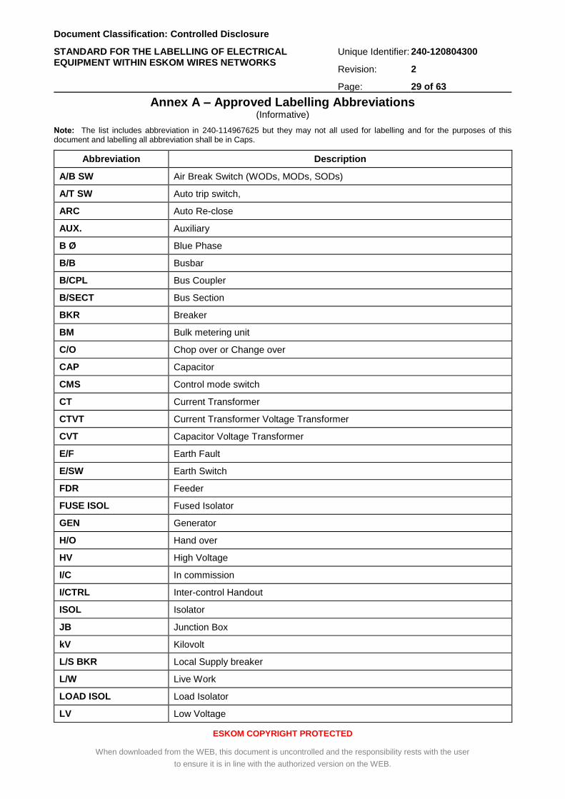
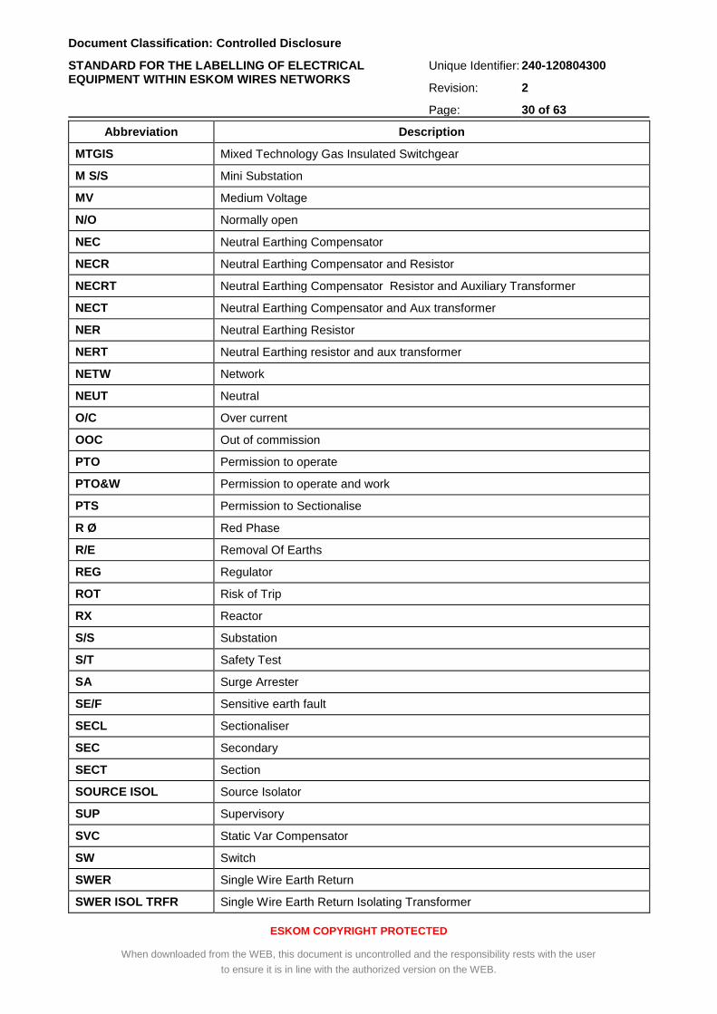
Annex A – Approved Labelling Abbreviations (Informative)
Note: The list includes abbreviation in 240-114967625 but they may not all used for labelling and for the purposes of this document and labelling all abbreviation shall be in Caps.
Abbreviation Description
A/B SW Air Break Switch (WODs, MODs, SODs)
A/T SW Auto trip switch,
ARC Auto Re-close
AUX. Auxiliary
B Ø Blue Phase
B/B Busbar
B/CPL Bus Coupler
B/SECT Bus Section
BKR Breaker
BM Bulk metering unit
C/O Chop over or Change over
CAP Capacitor
CMS Control mode switch
CT Current Transformer
CTVT Current Transformer Voltage Transformer
CVT Capacitor Voltage Transformer
E/F Earth Fault
E/SW Earth Switch
FDR Feeder
FUSE ISOL Fused Isolator
GEN Generator
H/O Hand over
HV High Voltage
I/C In commission
I/CTRL Inter-control Handout
ISOL Isolator
JB Junction Box
kV Kilovolt
L/S BKR Local Supply breaker
L/W Live Work
LOAD ISOL Load Isolator
LV Low Voltage
Document Classification: Controlled Disclosure
STANDARD FOR THE LABELLING OF ELECTRICAL EQUIPMENT WITHIN ESKOM WIRES NETWORKS
Unique Identifier: 240-120804300
Revision: 2
Page: 30 of 63
ESKOM COPYRIGHT PROTECTED
When downloaded from the WEB, this document is uncontrolled and the responsibility rests with the user
to ensure it is in line with the authorized version on the WEB.
Abbreviation Description
MTGIS Mixed Technology Gas Insulated Switchgear
M S/S Mini Substation
MV Medium Voltage
N/O Normally open
NEC Neutral Earthing Compensator
NECR Neutral Earthing Compensator and Resistor
NECRT Neutral Earthing Compensator Resistor and Auxiliary Transformer
NECT Neutral Earthing Compensator and Aux transformer
NER Neutral Earthing Resistor
NERT Neutral Earthing resistor and aux transformer
NETW Network
NEUT Neutral
O/C Over current
OOC Out of commission
PTO Permission to operate
PTO&W Permission to operate and work
PTS Permission to Sectionalise
R Ø Red Phase
R/E Removal Of Earths
REG Regulator
ROT Risk of Trip
RX Reactor
S/S Substation
S/T Safety Test
SA Surge Arrester
SE/F Sensitive earth fault
SECL Sectionaliser
SEC Secondary
SECT Section
SOURCE ISOL Source Isolator
SUP Supervisory
SVC Static Var Compensator
SW Switch
SWER Single Wire Earth Return
SWER ISOL TRFR Single Wire Earth Return Isolating Transformer
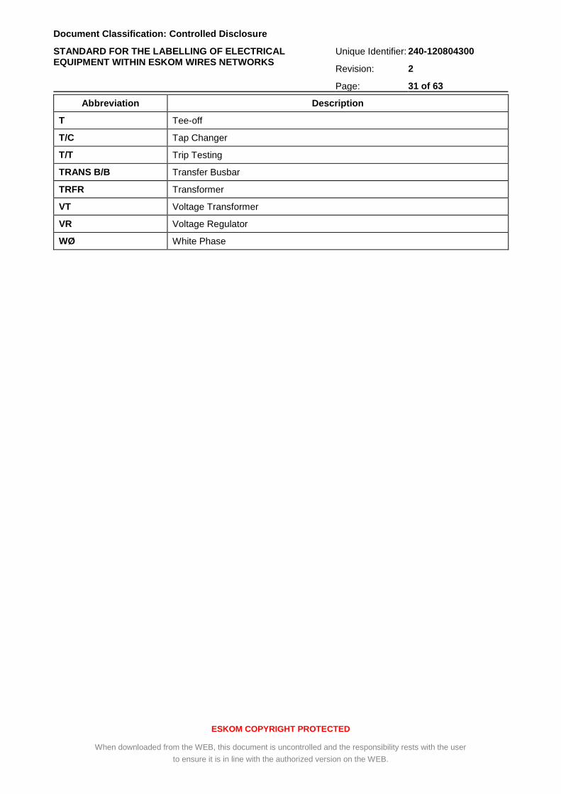
Document Classification: Controlled Disclosure
STANDARD FOR THE LABELLING OF ELECTRICAL EQUIPMENT WITHIN ESKOM WIRES NETWORKS
Unique Identifier: 240-120804300
Revision: 2
Page: 31 of 63
ESKOM COPYRIGHT PROTECTED
When downloaded from the WEB, this document is uncontrolled and the responsibility rests with the user
to ensure it is in line with the authorized version on the WEB.
Abbreviation Description
T Tee-off
T/C Tap Changer
T/T Trip Testing
TRANS B/B Transfer Busbar
TRFR Transformer
VT Voltage Transformer
VR Voltage Regulator
WØ White Phase
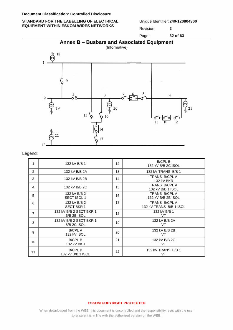
Document Classification: Controlled Disclosure
STANDARD FOR THE LABELLING OF ELECTRICAL EQUIPMENT WITHIN ESKOM WIRES NETWORKS
Unique Identifier: 240-120804300
Revision: 2
Page: 32 of 63
ESKOM COPYRIGHT PROTECTED
When downloaded from the WEB, this document is uncontrolled and the responsibility rests with the user
to ensure it is in line with the authorized version on the WEB.
Annex B – Busbars and Associated Equipment (Informative)
Legend:
1 132 kV B/B 1 12 B/CPL B
132 kV B/B 2C ISOL
2 132 kV B/B 2A 13 132 kV TRANS B/B 1
3 132 kV B/B 2B 14 TRANS B/CPL A
132 kV BKR
4 132 kV B/B 2C 15 TRANS B/CPL A
132 kV B/B 1 ISOL
5 132 kV B/B 2 SECT ISOL 1
16 TRANS B/CPL A
132 kV B/B 2B ISOL
6
132 kV B/B 2 SECT BKR 1
17
TRANS B/CPL A 132 kV TRANS B/B 1 ISOL
7 132 kV B/B 2 SECT BKR 1
B/B 2B ISOL 18
132 kV B/B 1 VT
8 132 kV B/B 2 SECT BKR 1
B/B 2C ISOL 19
132 kV B/B 2A VT
9 B/CPL A
132 kV ISOL 20
132 kV B/B 2B VT
10 B/CPL B
132 kV BKR 21
132 kV B/B 2C VT
11 B/CPL B
132 kV B/B 1 ISOL 22 132 kV TRANS B/B 1
VT
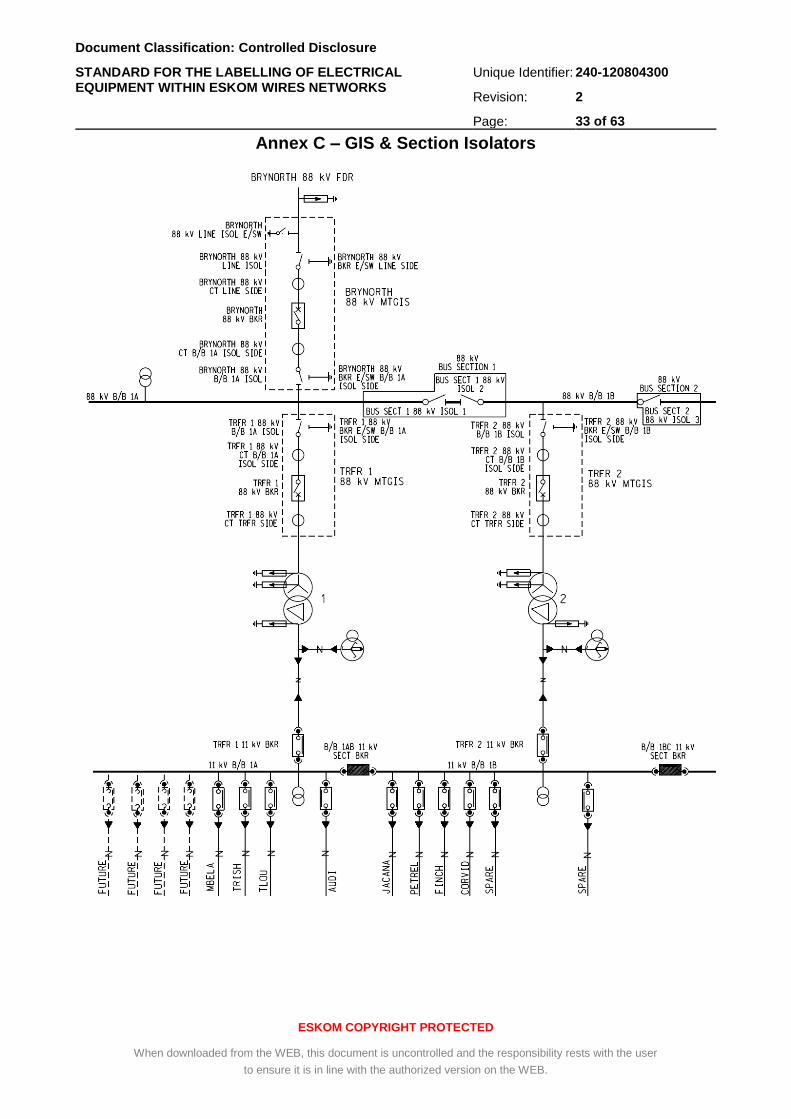
Document Classification: Controlled Disclosure
STANDARD FOR THE LABELLING OF ELECTRICAL EQUIPMENT WITHIN ESKOM WIRES NETWORKS
Unique Identifier: 240-120804300
Revision: 2
Page: 33 of 63
ESKOM COPYRIGHT PROTECTED
When downloaded from the WEB, this document is uncontrolled and the responsibility rests with the user
to ensure it is in line with the authorized version on the WEB.
Annex C – GIS & Section Isolators
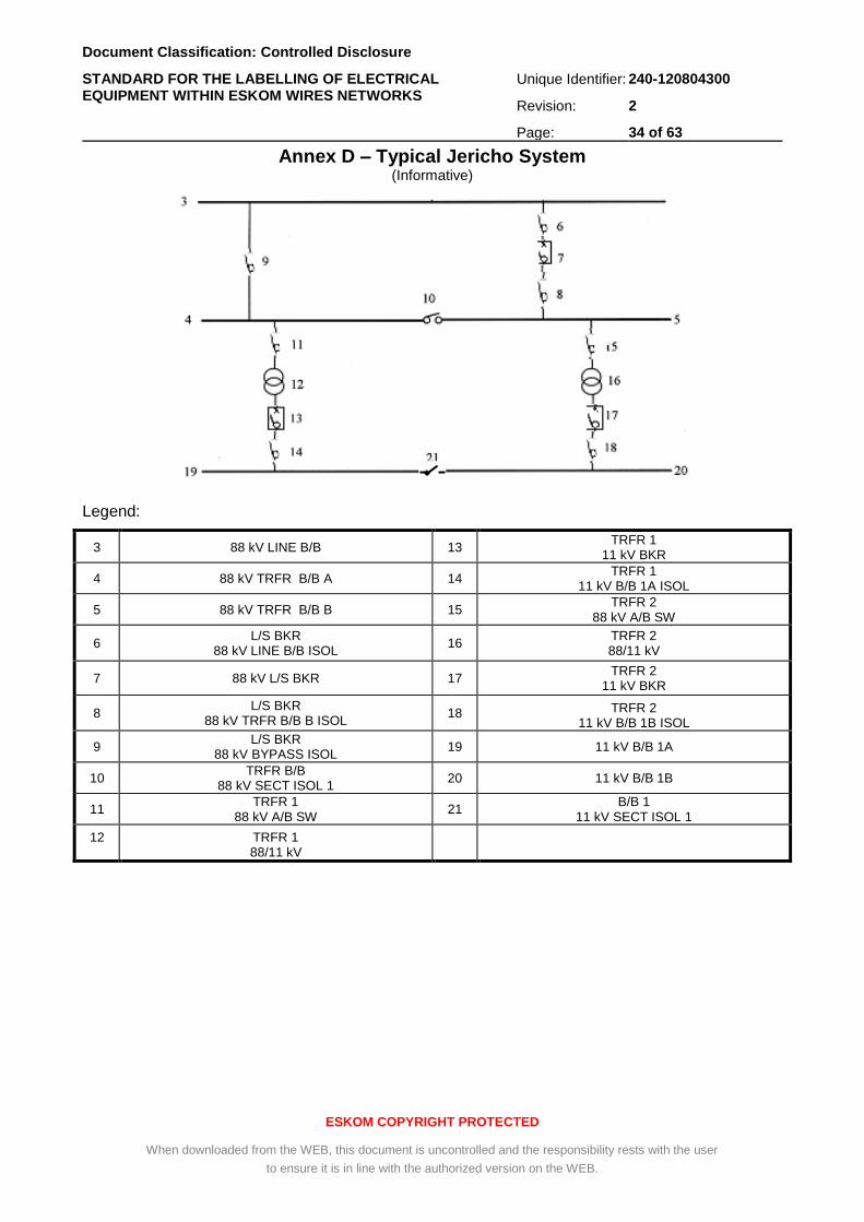
Document Classification: Controlled Disclosure
STANDARD FOR THE LABELLING OF ELECTRICAL EQUIPMENT WITHIN ESKOM WIRES NETWORKS
Unique Identifier: 240-120804300
Revision: 2
Page: 34 of 63
ESKOM COPYRIGHT PROTECTED
When downloaded from the WEB, this document is uncontrolled and the responsibility rests with the user
to ensure it is in line with the authorized version on the WEB.
Annex D – Typical Jericho System (Informative)
Legend:
3 88 kV LINE B/B 13 TRFR 1
11 kV BKR
4 88 kV TRFR B/B A 14 TRFR 1
11 kV B/B 1A ISOL
5 88 kV TRFR B/B B 15 TRFR 2
88 kV A/B SW
6 L/S BKR
88 kV LINE B/B ISOL 16
TRFR 2 88/11 kV
7 88 kV L/S BKR 17 TRFR 2
11 kV BKR
8 L/S BKR
88 kV TRFR B/B B ISOL 18 TRFR 2
11 kV B/B 1B ISOL
9 L/S BKR
88 kV BYPASS ISOL 19 11 kV B/B 1A
10 TRFR B/B
88 kV SECT ISOL 1 20 11 kV B/B 1B
11 TRFR 1
88 kV A/B SW 21
B/B 1 11 kV SECT ISOL 1
12
TRFR 1 88/11 kV
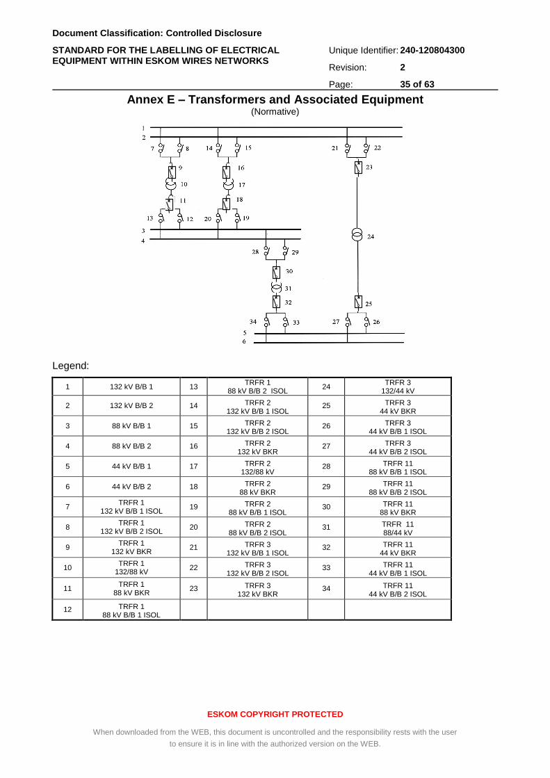
Document Classification: Controlled Disclosure
STANDARD FOR THE LABELLING OF ELECTRICAL EQUIPMENT WITHIN ESKOM WIRES NETWORKS
Unique Identifier: 240-120804300
Revision: 2
Page: 35 of 63
ESKOM COPYRIGHT PROTECTED
When downloaded from the WEB, this document is uncontrolled and the responsibility rests with the user
to ensure it is in line with the authorized version on the WEB.
Annex E – Transformers and Associated Equipment (Normative)
Legend:
1 132 kV B/B 1 13 TRFR 1
88 kV B/B 2 ISOL 24
TRFR 3 132/44 kV
2 132 kV B/B 2 14 TRFR 2 132 kV B/B 1 ISOL
25 TRFR 3 44 kV BKR
3 88 kV B/B 1 15 TRFR 2 132 kV B/B 2 ISOL
26 TRFR 3 44 kV B/B 1 ISOL
4 88 kV B/B 2 16 TRFR 2 132 kV BKR
27 TRFR 3 44 kV B/B 2 ISOL
5 44 kV B/B 1 17 TRFR 2 132/88 kV
28 TRFR 11 88 kV B/B 1 ISOL
6 44 kV B/B 2 18 TRFR 2 88 kV BKR
29 TRFR 11 88 kV B/B 2 ISOL
7 TRFR 1
132 kV B/B 1 ISOL 19 TRFR 2
88 kV B/B 1 ISOL 30 TRFR 11
88 kV BKR
8 TRFR 1
132 kV B/B 2 ISOL 20 TRFR 2
88 kV B/B 2 ISOL 31 TRFR 11
88/44 kV
9 TRFR 1
132 kV BKR 21 TRFR 3
132 kV B/B 1 ISOL 32 TRFR 11
44 kV BKR
10 TRFR 1
132/88 kV 22 TRFR 3
132 kV B/B 2 ISOL 33 TRFR 11
44 kV B/B 1 ISOL
11 TRFR 1
88 kV BKR 23 TRFR 3
132 kV BKR 34 TRFR 11
44 kV B/B 2 ISOL
12 TRFR 1 88 kV B/B 1 ISOL
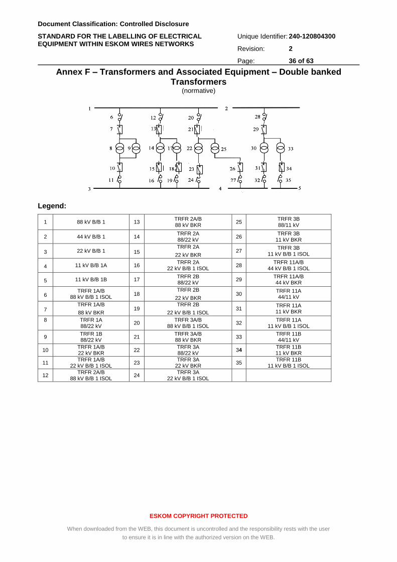
Document Classification: Controlled Disclosure
STANDARD FOR THE LABELLING OF ELECTRICAL EQUIPMENT WITHIN ESKOM WIRES NETWORKS
Unique Identifier: 240-120804300
Revision: 2
Page: 36 of 63
ESKOM COPYRIGHT PROTECTED
When downloaded from the WEB, this document is uncontrolled and the responsibility rests with the user
to ensure it is in line with the authorized version on the WEB.
Annex F – Transformers and Associated Equipment – Double banked Transformers
(normative)
Legend:
1 88 kV B/B 1 13 TRFR 2A/B 88 kV BKR
25 TRFR 3B 88/11 kV
2 44 kV B/B 1 14 TRFR 2A 88/22 kV
26 TRFR 3B
11 kV BKR
3 22 kV B/B 1 15 TRFR 2A
22 kV BKR 27
TRFR 3B 11 kV B/B 1 ISOL
4 11 kV B/B 1A 16 TRFR 2A
22 kV B/B 1 ISOL 28
TRFR 11A/B 44 kV B/B 1 ISOL
5 11 kV B/B 1B 17 TRFR 2B 88/22 kV
29 TRFR 11A/B 44 kV BKR
6 TRFR 1A/B
88 kV B/B 1 ISOL 18
TRFR 2B
22 kV BKR 30
TRFR 11A 44/11 kV
7 TRFR 1A/B
88 kV BKR 19
TRFR 2B
22 kV B/B 1 ISOL 31
TRFR 11A 11 kV BKR
8
TRFR 1A 88/22 kV
20 TRFR 3A/B
88 kV B/B 1 ISOL 32
TRFR 11A 11 kV B/B 1 ISOL
9 TRFR 1B 88/22 kV
21 TRFR 3A/B 88 kV BKR
33 TRFR 11B 44/11 kV
10 TRFR 1A/B 22 kV BKR
22 TRFR 3A 88/22 kV
34 TRFR 11B 11 kV BKR
11 TRFR 1A/B
22 kV B/B 1 ISOL 23
TRFR 3A 22 kV BKR
35 TRFR 11B
11 kV B/B 1 ISOL
12 TRFR 2A/B
88 kV B/B 1 ISOL 24
TRFR 3A 22 kV B/B 1 ISOL
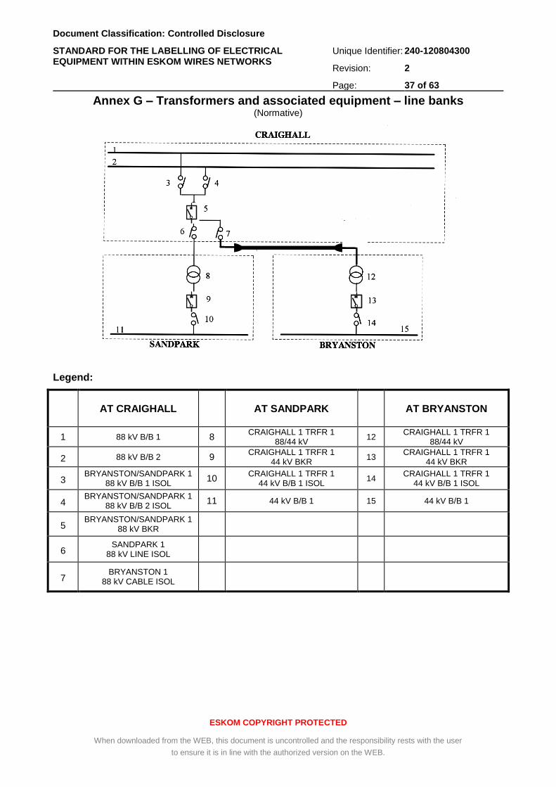
Document Classification: Controlled Disclosure
STANDARD FOR THE LABELLING OF ELECTRICAL EQUIPMENT WITHIN ESKOM WIRES NETWORKS
Unique Identifier: 240-120804300
Revision: 2
Page: 37 of 63
ESKOM COPYRIGHT PROTECTED
When downloaded from the WEB, this document is uncontrolled and the responsibility rests with the user
to ensure it is in line with the authorized version on the WEB.
Annex G – Transformers and associated equipment – line banks (Normative)
Legend:
AT CRAIGHALL AT SANDPARK
AT BRYANSTON
1 88 kV B/B 1 8 CRAIGHALL 1 TRFR 1
88/44 kV 12
CRAIGHALL 1 TRFR 1 88/44 kV
2 88 kV B/B 2 9 CRAIGHALL 1 TRFR 1
44 kV BKR 13
CRAIGHALL 1 TRFR 1 44 kV BKR
3 BRYANSTON/SANDPARK 1
88 kV B/B 1 ISOL 10
CRAIGHALL 1 TRFR 1 44 kV B/B 1 ISOL
14 CRAIGHALL 1 TRFR 1
44 kV B/B 1 ISOL
4 BRYANSTON/SANDPARK 1
88 kV B/B 2 ISOL 11 44 kV B/B 1 15 44 kV B/B 1
5 BRYANSTON/SANDPARK 1
88 kV BKR
6 SANDPARK 1
88 kV LINE ISOL
7 BRYANSTON 1
88 kV CABLE ISOL
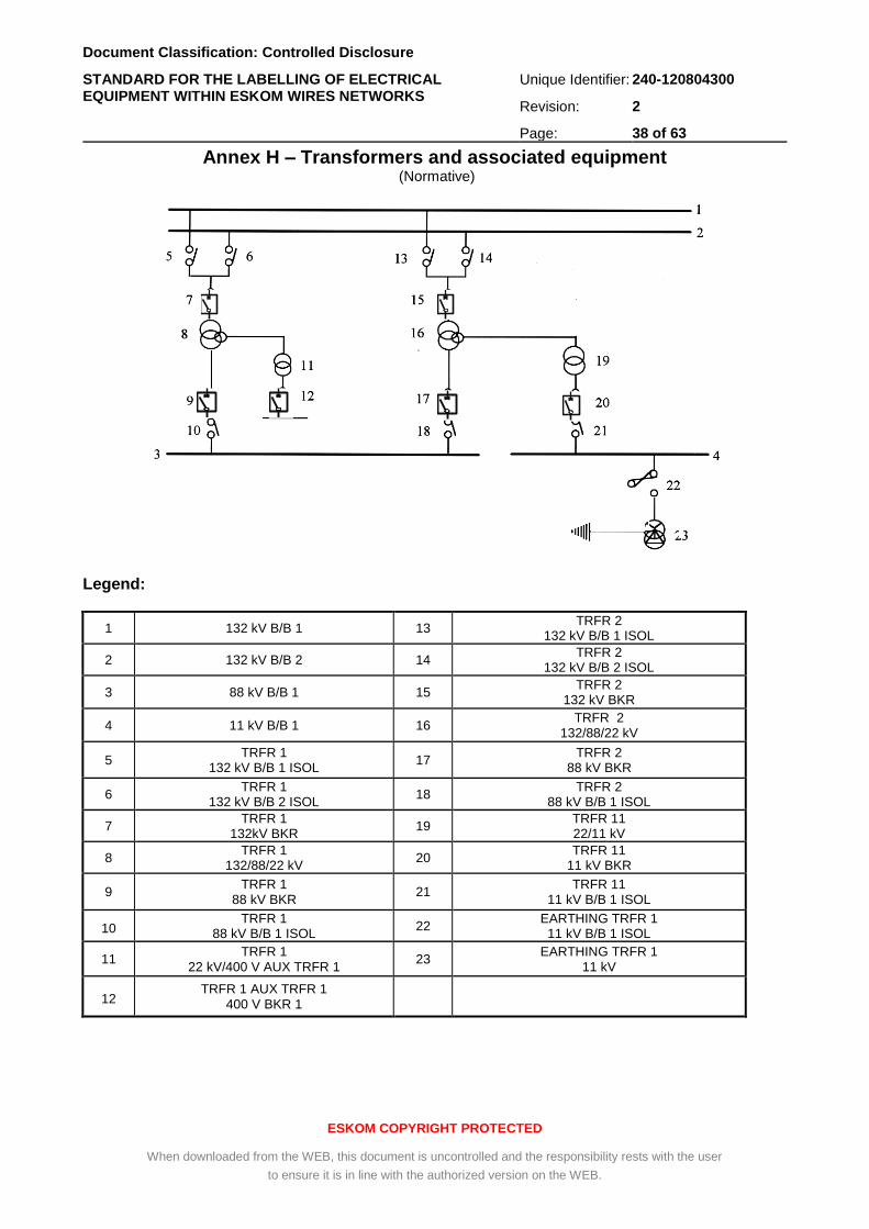
Document Classification: Controlled Disclosure
STANDARD FOR THE LABELLING OF ELECTRICAL EQUIPMENT WITHIN ESKOM WIRES NETWORKS
Unique Identifier: 240-120804300
Revision: 2
Page: 38 of 63
ESKOM COPYRIGHT PROTECTED
When downloaded from the WEB, this document is uncontrolled and the responsibility rests with the user
to ensure it is in line with the authorized version on the WEB.
Annex H – Transformers and associated equipment (Normative)
Legend:
1 132 kV B/B 1 13 TRFR 2
132 kV B/B 1 ISOL
2 132 kV B/B 2 14 TRFR 2
132 kV B/B 2 ISOL
3 88 kV B/B 1 15 TRFR 2
132 kV BKR
4 11 kV B/B 1 16 TRFR 2
132/88/22 kV
5 TRFR 1
132 kV B/B 1 ISOL 17
TRFR 2 88 kV BKR
6 TRFR 1
132 kV B/B 2 ISOL 18
TRFR 2 88 kV B/B 1 ISOL
7 TRFR 1
132kV BKR 19
TRFR 11 22/11 kV
8 TRFR 1
132/88/22 kV 20
TRFR 11 11 kV BKR
9 TRFR 1
88 kV BKR 21
TRFR 11 11 kV B/B 1 ISOL
10 TRFR 1
88 kV B/B 1 ISOL 22
EARTHING TRFR 1 11 kV B/B 1 ISOL
11 TRFR 1
22 kV/400 V AUX TRFR 1 23
EARTHING TRFR 1 11 kV
12 TRFR 1 AUX TRFR 1
400 V BKR 1
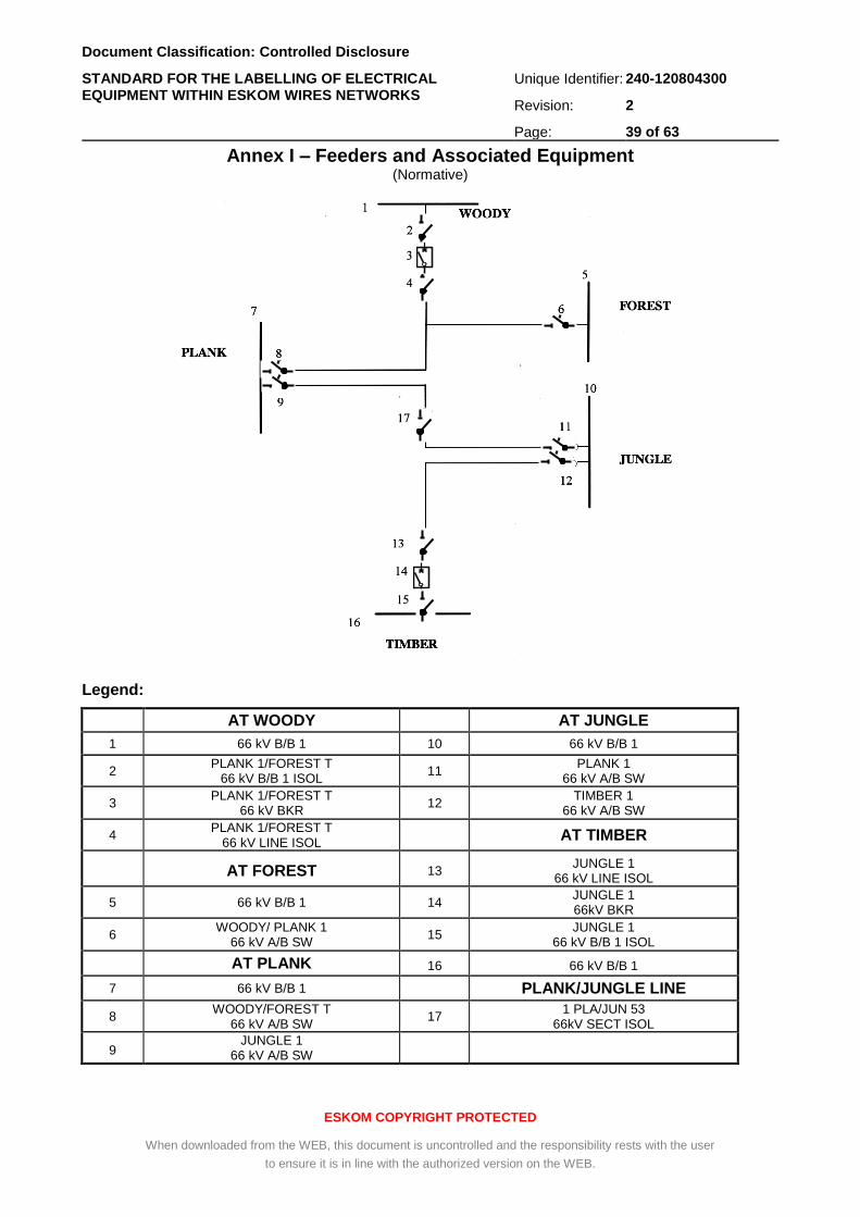
Document Classification: Controlled Disclosure
STANDARD FOR THE LABELLING OF ELECTRICAL EQUIPMENT WITHIN ESKOM WIRES NETWORKS
Unique Identifier: 240-120804300
Revision: 2
Page: 39 of 63
ESKOM COPYRIGHT PROTECTED
When downloaded from the WEB, this document is uncontrolled and the responsibility rests with the user
to ensure it is in line with the authorized version on the WEB.
Annex I – Feeders and Associated Equipment (Normative)
Legend:
AT WOODY AT JUNGLE
1 66 kV B/B 1 10 66 kV B/B 1
2 PLANK 1/FOREST T
66 kV B/B 1 ISOL 11
PLANK 1 66 kV A/B SW
3 PLANK 1/FOREST T
66 kV BKR 12
TIMBER 1 66 kV A/B SW
4 PLANK 1/FOREST T
66 kV LINE ISOL AT TIMBER
AT FOREST 13 JUNGLE 1
66 kV LINE ISOL
5 66 kV B/B 1 14 JUNGLE 1 66kV BKR
6 WOODY/ PLANK 1
66 kV A/B SW 15
JUNGLE 1 66 kV B/B 1 ISOL
AT PLANK 16 66 kV B/B 1
7 66 kV B/B 1 PLANK/JUNGLE LINE
8 WOODY/FOREST T
66 kV A/B SW 17
1 PLA/JUN 53 66kV SECT ISOL
9 JUNGLE 1
66 kV A/B SW
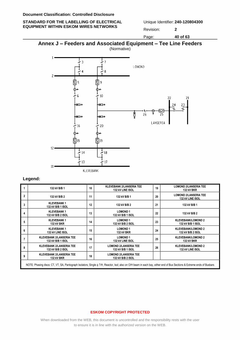
Document Classification: Controlled Disclosure
STANDARD FOR THE LABELLING OF ELECTRICAL EQUIPMENT WITHIN ESKOM WIRES NETWORKS
Unique Identifier: 240-120804300
Revision: 2
Page: 40 of 63
ESKOM COPYRIGHT PROTECTED
When downloaded from the WEB, this document is uncontrolled and the responsibility rests with the user
to ensure it is in line with the authorized version on the WEB.
Annex J – Feeders and Associated Equipment – Tee Line Feeders (Normative)
Legend:
1 132 kV B/B 1 10 KLEVEBANK 2/LANSERIA TEE
132 kV LINE ISOL 19
LOMOND 2/LANSERIA TEE 132 kV BKR
2 132 kV B/B 2 11 132 kV B/B 1 20 LOMOND 2/LANSERIA TEE
132 kV LINE ISOL
3 KLEVEBANK 1
132 kV B/B 1 ISOL 12 132 kV B/B 2 21 132 kV B/B 1
4 KLEVEBANK 1
132 kV B/B 2 ISOL 13
LOMOND 1 132 kV B/B 1 ISOL
22 132 kV B/B 2
5 KLEVEBANK 1
132 kV BKR 14
LOMOND 1 132 kV B/B 2 ISOL
23 KLEVEBANK/LOMOND 2
132 kV B/B 1 ISOL
6 KLEVEBANK 1
132 kV LINE ISOL 15
LOMOND 1 132 kV BKR
24 KLEVEBANK/LOMOND 2
132 kV B/B 2 ISOL
7 KLEVEBANK 2/LANSERIA TEE
132 kV B/B 1 ISOL 16
LOMOND 1 132 kV LINE ISOL
25 KLEVEBANK/LOMOND 2
132 kV BKR
8 KLEVEBANK 2/LANSERIA TEE
132 kV B/B 2 ISOL 17
LOMOND 2/LANSERIA TEE 132 kV B/B 1 ISOL
26 KLEVEBANK/LOMOND 2
132 kV LINE ISOL
9 KLEVEBANK 2/LANSERIA TEE
132 kV BKR 18
LOMOND 2/LANSERIA TEE 132 kV B/B 2 ISOL
NOTE: Phasing discs: CT, VT, SA, Pantograph Isolators; Single Trfr, Reactor, Isol; also on O/H beam in each bay, either end of Bus Sections & Extreme ends of Busbars
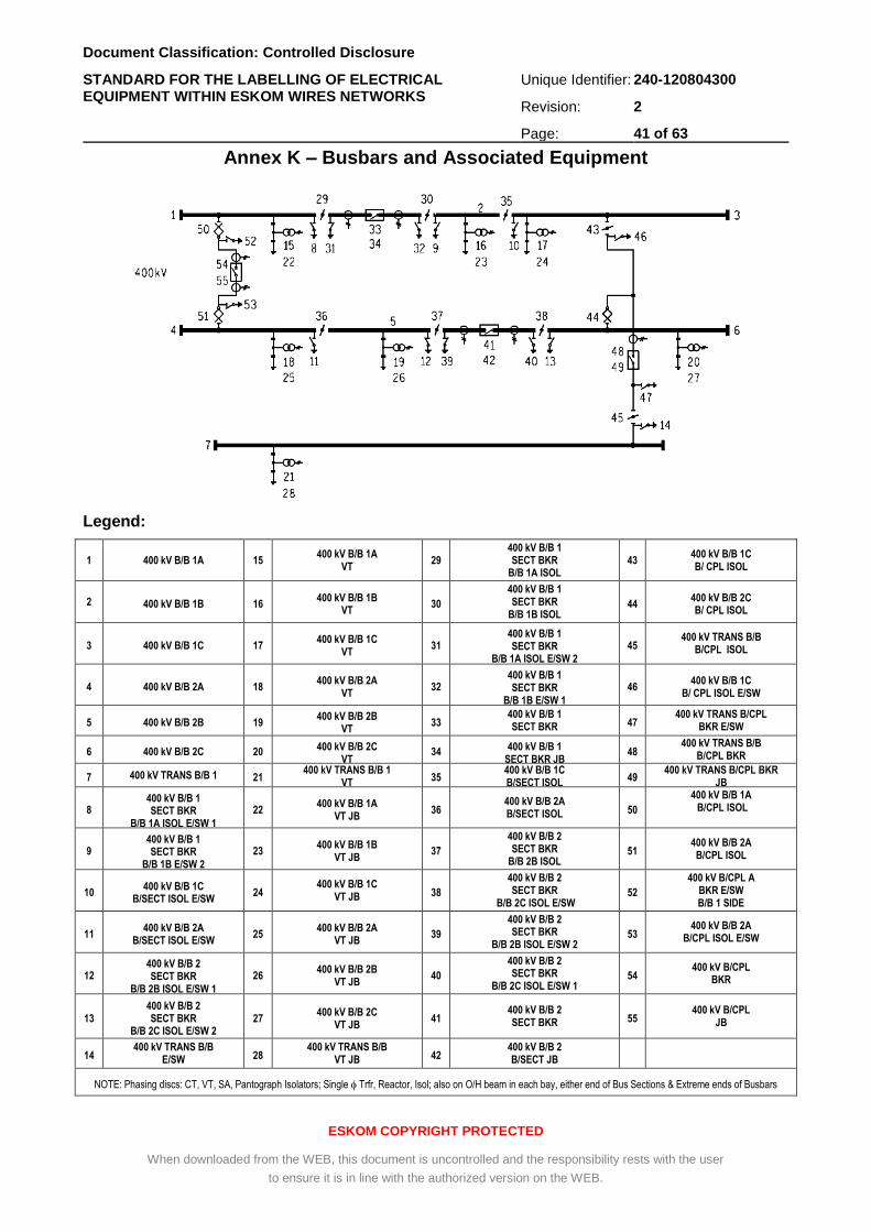
Document Classification: Controlled Disclosure
STANDARD FOR THE LABELLING OF ELECTRICAL EQUIPMENT WITHIN ESKOM WIRES NETWORKS
Unique Identifier: 240-120804300
Revision: 2
Page: 41 of 63
ESKOM COPYRIGHT PROTECTED
When downloaded from the WEB, this document is uncontrolled and the responsibility rests with the user
to ensure it is in line with the authorized version on the WEB.
Annex K – Busbars and Associated Equipment
Legend:
1 400 kV B/B 1A 15 400 kV B/B 1A
VT 29
400 kV B/B 1 SECT BKR
B/B 1A ISOL 43
400 kV B/B 1C B/ CPL ISOL
2 400 kV B/B 1B 16 400 kV B/B 1B
VT 30
400 kV B/B 1 SECT BKR
B/B 1B ISOL 44
400 kV B/B 2C B/ CPL ISOL
3 400 kV B/B 1C 17 400 kV B/B 1C
VT 31
400 kV B/B 1 SECT BKR
B/B 1A ISOL E/SW 2
45 400 kV TRANS B/B
B/CPL ISOL
4 400 kV B/B 2A 18 400 kV B/B 2A
VT 32
400 kV B/B 1 SECT BKR
B/B 1B E/SW 1
46 400 kV B/B 1C
B/ CPL ISOL E/SW
5 400 kV B/B 2B 19 400 kV B/B 2B
VT 33
400 kV B/B 1 SECT BKR 47
400 kV TRANS B/CPL BKR E/SW
6 400 kV B/B 2C 20 400 kV B/B 2C VT
34 400 kV B/B 1 SECT BKR JB
48 400 kV TRANS B/B
B/CPL BKR
7 400 kV TRANS B/B 1 21 400 kV TRANS B/B 1
VT 35
400 kV B/B 1C B/SECT ISOL
49 400 kV TRANS B/CPL BKR
JB
8 400 kV B/B 1 SECT BKR
B/B 1A ISOL E/SW 1
22 400 kV B/B 1A
VT JB 36
400 kV B/B 2A B/SECT ISOL 50
400 kV B/B 1A B/CPL ISOL
9 400 kV B/B 1 SECT BKR
B/B 1B E/SW 2
23 400 kV B/B 1B
VT JB 37
400 kV B/B 2 SECT BKR
B/B 2B ISOL 51
400 kV B/B 2A B/CPL ISOL
10 400 kV B/B 1C
B/SECT ISOL E/SW 24
400 kV B/B 1C VT JB 38
400 kV B/B 2 SECT BKR
B/B 2C ISOL E/SW 52
400 kV B/CPL A BKR E/SW B/B 1 SIDE
11 400 kV B/B 2A
B/SECT ISOL E/SW 25
400 kV B/B 2A VT JB
39
400 kV B/B 2 SECT BKR
B/B 2B ISOL E/SW 2 53
400 kV B/B 2A B/CPL ISOL E/SW
12 400 kV B/B 2 SECT BKR
B/B 2B ISOL E/SW 1
26 400 kV B/B 2B
VT JB 40
400 kV B/B 2 SECT BKR
B/B 2C ISOL E/SW 1 54
400 kV B/CPL BKR
13 400 kV B/B 2 SECT BKR
B/B 2C ISOL E/SW 2 27
400 kV B/B 2C VT JB
41 400 kV B/B 2 SECT BKR 55
400 kV B/CPL JB
14 400 kV TRANS B/B
E/SW 28 400 kV TRANS B/B
VT JB 42 400 kV B/B 2 B/SECT JB
NOTE: Phasing discs: CT, VT, SA, Pantograph Isolators; Single Trfr, Reactor, Isol; also on O/H beam in each bay, either end of Bus Sections & Extreme ends of Busbars
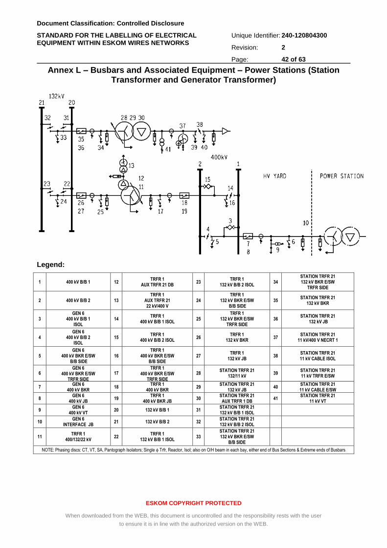
Document Classification: Controlled Disclosure
STANDARD FOR THE LABELLING OF ELECTRICAL EQUIPMENT WITHIN ESKOM WIRES NETWORKS
Unique Identifier: 240-120804300
Revision: 2
Page: 42 of 63
ESKOM COPYRIGHT PROTECTED
When downloaded from the WEB, this document is uncontrolled and the responsibility rests with the user
to ensure it is in line with the authorized version on the WEB.
Annex L – Busbars and Associated Equipment – Power Stations (Station Transformer and Generator Transformer)
Legend:
1 400 kV B/B 1 12 TRFR 1
AUX TRFR 21 DB 23
TRFR 1 132 kV B/B 2 ISOL
34 STATION TRFR 21 132 kV BKR E/SW
TRFR SIDE
2 400 kV B/B 2 13 TRFR 1
AUX TRFR 21 22 kV/400 V
24 TRFR 1
132 kV BKR E/SW B/B SIDE
35 STATION TRFR 21
132 kV BKR
3 GEN 6
400 kV B/B 1 ISOL
14 TRFR 1
400 kV B/B 1 ISOL 25
TRFR 1 132 kV BKR E/SW
TRFR SIDE 36
STATION TRFR 21 132 kV JB
4 GEN 6
400 kV B/B 2 ISOL
15 TRFR 1
400 kV B/B 2 ISOL 26
TRFR 1 132 kV BKR
37 STATION TRFR 21
11 kV/400 V NECRT 1
5 GEN 6
400 kV BKR E/SW B/B SIDE
16 TRFR 1
400 kV BKR E/SW B/B SIDE
27 TRFR 1
132 kV JB 38
STATION TRFR 21 11 kV CABLE ISOL
6 GEN 6
400 kV BKR E/SW TRFR SIDE
17 TRFR 1
400 kV BKR E/SW TRFR SIDE
28 STATION TRFR 21
132/11 kV 39
STATION TRFR 21 11 kV TRFR E/SW
7 GEN 6
400 kV BKR 18
TRFR 1 400 kV BKR
29 STATION TRFR 21
132 kV JB 40
STATION TRFR 21 11 kV CABLE E/SW
8 GEN 6
400 kV JB 19
TRFR 1 400 kV BKR JB
30 STATION TRFR 21
AUX TRFR 1 DB 41
STATION TRFR 21 11 kV VT
9 GEN 6
400 kV VT 20 132 kV B/B 1 31
STATION TRFR 21 132 kV B/B 1 ISOL
10 GEN 6
INTERFACE JB 21 132 kV B/B 2 32
STATION TRFR 21 132 kV B/B 2 ISOL
11 TRFR 1
400/132/22 kV 22
TRFR 1 132 kV B/B 1 ISOL
33 STATION TRFR 21 132 kV BKR E/SW
B/B SIDE
NOTE: Phasing discs: CT, VT, SA, Pantograph Isolators; Single Trfr, Reactor, Isol; also on O/H beam in each bay, either end of Bus Sections & Extreme ends of Busbars
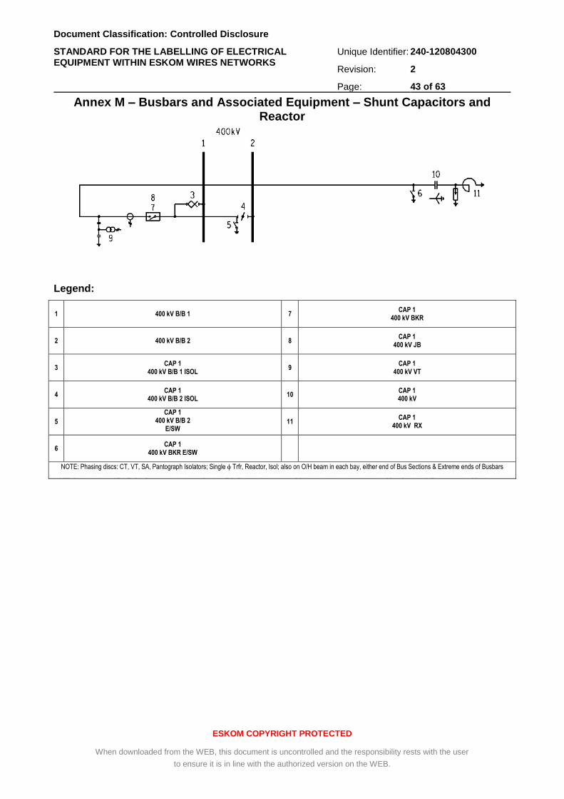
Document Classification: Controlled Disclosure
STANDARD FOR THE LABELLING OF ELECTRICAL EQUIPMENT WITHIN ESKOM WIRES NETWORKS
Unique Identifier: 240-120804300
Revision: 2
Page: 43 of 63
ESKOM COPYRIGHT PROTECTED
When downloaded from the WEB, this document is uncontrolled and the responsibility rests with the user
to ensure it is in line with the authorized version on the WEB.
Annex M – Busbars and Associated Equipment – Shunt Capacitors and Reactor
Legend:
1 400 kV B/B 1 7 CAP 1
400 kV BKR
2 400 kV B/B 2 8 CAP 1
400 kV JB
3 CAP 1
400 kV B/B 1 ISOL 9
CAP 1 400 kV VT
4 CAP 1
400 kV B/B 2 ISOL 10
CAP 1 400 kV
5
CAP 1 400 kV B/B 2
E/SW
11 CAP 1
400 kV RX
6 CAP 1
400 kV BKR E/SW
NOTE: Phasing discs: CT, VT, SA, Pantograph Isolators; Single Trfr, Reactor, Isol; also on O/H beam in each bay, either end of Bus Sections & Extreme ends of Busbars
NOTE: Phasing discs: CT, VT, SA, Pantograph Isolators; Single Trfr, Reactor, Isol; also on O/H beam in each bay, either end of Bus Sections & Extreme ends of Busbars
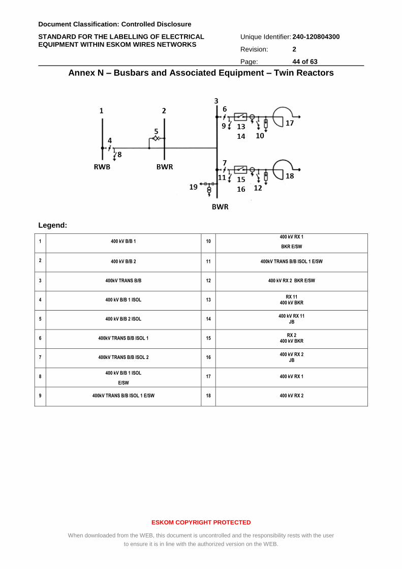
Document Classification: Controlled Disclosure
STANDARD FOR THE LABELLING OF ELECTRICAL EQUIPMENT WITHIN ESKOM WIRES NETWORKS
Unique Identifier: 240-120804300
Revision: 2
Page: 44 of 63
ESKOM COPYRIGHT PROTECTED
When downloaded from the WEB, this document is uncontrolled and the responsibility rests with the user
to ensure it is in line with the authorized version on the WEB.
Annex N – Busbars and Associated Equipment – Twin Reactors
Legend:
1 400 kV B/B 1 10 400 kV RX 1
BKR E/SW
2 400 kV B/B 2 11 400kV TRANS B/B ISOL 1 E/SW
3 400kV TRANS B/B 12 400 kV RX 2 BKR E/SW
4 400 kV B/B 1 ISOL 13 RX 11
400 kV BKR
5 400 kV B/B 2 ISOL 14 400 kV RX 11
JB
6 400kV TRANS B/B ISOL 1 15 RX 2
400 kV BKR
7 400kV TRANS B/B ISOL 2 16 400 kV RX 2
JB
8 400 kV B/B 1 ISOL
E/SW
17 400 kV RX 1
9 400kV TRANS B/B ISOL 1 E/SW 18 400 kV RX 2
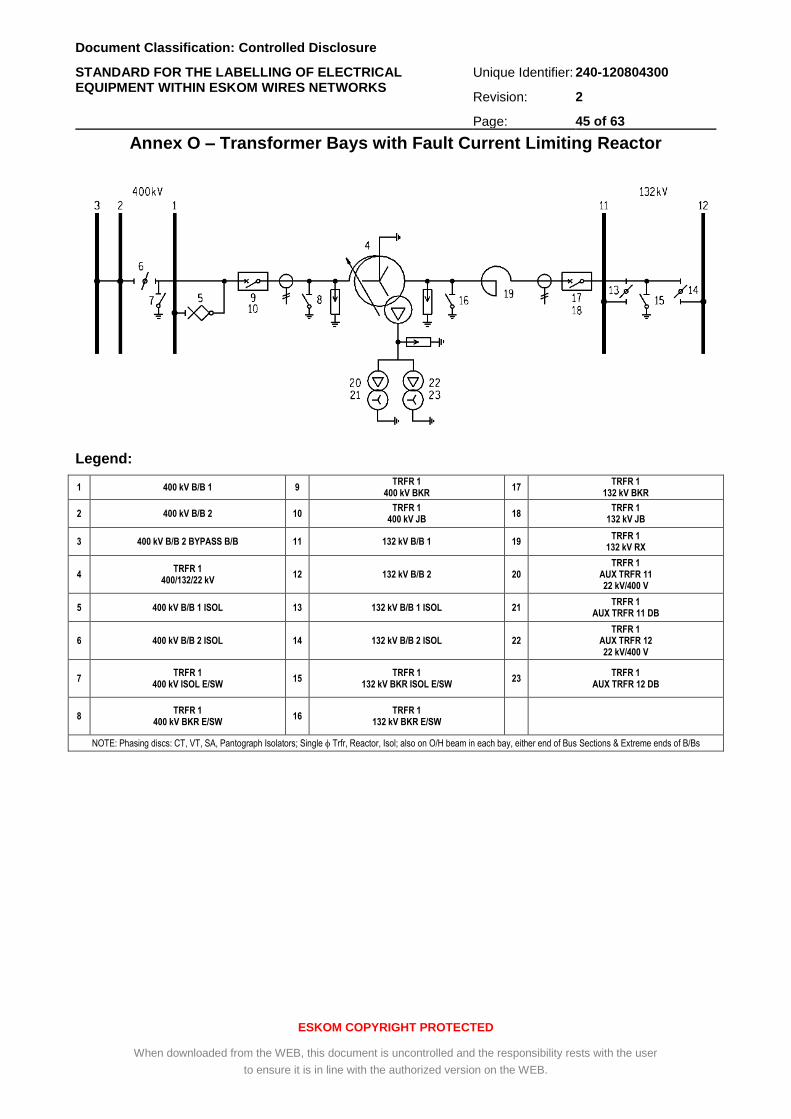
Document Classification: Controlled Disclosure
STANDARD FOR THE LABELLING OF ELECTRICAL EQUIPMENT WITHIN ESKOM WIRES NETWORKS
Unique Identifier: 240-120804300
Revision: 2
Page: 45 of 63
ESKOM COPYRIGHT PROTECTED
When downloaded from the WEB, this document is uncontrolled and the responsibility rests with the user
to ensure it is in line with the authorized version on the WEB.
Annex O – Transformer Bays with Fault Current Limiting Reactor
Legend:
1 400 kV B/B 1 9 TRFR 1
400 kV BKR 17
TRFR 1 132 kV BKR
2 400 kV B/B 2 10 TRFR 1
400 kV JB 18
TRFR 1 132 kV JB
3 400 kV B/B 2 BYPASS B/B 11 132 kV B/B 1 19 TRFR 1
132 kV RX
4 TRFR 1
400/132/22 kV 12 132 kV B/B 2 20
TRFR 1 AUX TRFR 11 22 kV/400 V
5 400 kV B/B 1 ISOL 13 132 kV B/B 1 ISOL 21 TRFR 1
AUX TRFR 11 DB
6 400 kV B/B 2 ISOL 14 132 kV B/B 2 ISOL 22 TRFR 1
AUX TRFR 12 22 kV/400 V
7 TRFR 1
400 kV ISOL E/SW 15
TRFR 1 132 kV BKR ISOL E/SW
23 TRFR 1
AUX TRFR 12 DB
8 TRFR 1
400 kV BKR E/SW 16
TRFR 1 132 kV BKR E/SW
NOTE: Phasing discs: CT, VT, SA, Pantograph Isolators; Single Trfr, Reactor, Isol; also on O/H beam in each bay, either end of Bus Sections & Extreme ends of B/Bs
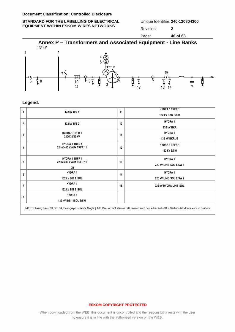
Document Classification: Controlled Disclosure
STANDARD FOR THE LABELLING OF ELECTRICAL EQUIPMENT WITHIN ESKOM WIRES NETWORKS
Unique Identifier: 240-120804300
Revision: 2
Page: 46 of 63
ESKOM COPYRIGHT PROTECTED
When downloaded from the WEB, this document is uncontrolled and the responsibility rests with the user
to ensure it is in line with the authorized version on the WEB.
Annex P – Transformers and Associated Equipment - Line Banks
Legend:
1 132 kV B/B 1 9 HYDRA 1 TRFR 1
132 kV BKR E/SW
2 132 kV B/B 2 10 HYDRA 1
132 kV BKR
3 HYDRA 1 TRFR 1
220/132/22 kV 11
HYDRA 1
132 kV BKR JB
4
HYDRA 1 TRFR 1 22 kV/400 V AUX TRFR 11
12 HYDRA 1 TRFR 1
132 kV E/SW
5 HYDRA 1 TRFR 1
22 kV/400 V AUX TRFR 11
DB
13 HYDRA 1
220 kV LINE ISOL E/SW 1
6 HYDRA 1
132 kV B/B 1 ISOL
14 HYDRA 1
220 kV LINE ISOL E/SW 2
7 HYDRA 1
132 kV B/B 2 ISOL
15 220 kV HYDRA LINE ISOL
8 HYDRA 1
132 kV B/B 1 ISOL E/SW
NOTE: Phasing discs: CT, VT, SA, Pantograph Isolators; Single Trfr, Reactor, Isol; also on O/H beam in each bay, either end of Bus Sections & Extreme ends of Busbars
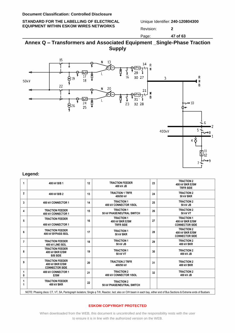
Document Classification: Controlled Disclosure
STANDARD FOR THE LABELLING OF ELECTRICAL EQUIPMENT WITHIN ESKOM WIRES NETWORKS
Unique Identifier: 240-120804300
Revision: 2
Page: 47 of 63
ESKOM COPYRIGHT PROTECTED
When downloaded from the WEB, this document is uncontrolled and the responsibility rests with the user
to ensure it is in line with the authorized version on the WEB.
Annex Q – Transformers and Associated Equipment _Single-Phase Traction Supply
Legend:
1 400 kV B/B 1 12 TRACTION FEEDER 400 kV JB
23 TRACTION 2
400 kV BKR E/SW TRFR SIDE
2 400 kV B/B 2 13 TRACTION 1 TRFR 400/50 kV
24 TRACTION 2 50 kV BKR
3 400 kV CONNECTOR 1 14 TRACTION 1 400 kV CONNECTOR 1ISOL
25 TRACTION 2 50 kV JB
4 TRACTION FEEDER 400 kV CONNECTOR 1
B/B 1 ISOL
15 TRACTION 1 50 kV PHASE/NEUTRAL SWITCH
26 TRACTION 2 50 kV VT
5 TRACTION FEEDER
400 kV CONNECTOR 1
B/B 2 ISOL
16 TRACTION 1
400 kV BKR E/SW TRFR SIDE
27 TRACTION 1
400 kV BKR E/SW CONNECTOR SIDE
6 TRACTION FEEDER
400 kV BYPASS ISOL 17 TRACTION 1
50 kV BKR 28
TRACTION 2 400 kV BKR E/SW
CONNECTOR SIDE
7 TRACTION FEEDER 400 kV LINE ISOL
18 TRACTION 1 50 kV JB
29 TRACTION 2 400 kV BKR
8 TRACTION FEEDER 400 kV BKR E/SW
B/B SIDE
19 TRACTION 1 50 kV VT
30 TRACTION 2 400 kV JB
9 TRACTION FEEDER 400 kV BKR E/SW
CONNECTOR SIDE
20 TRACTION 2 TRFR 400/50 kV
31 TRACTION 2 400 kV BKR
10
400 kV CONNECTOR 1 E/SW
21 TRACTION 2 400 kV CONNECTOR 1ISOL
32 TRACTION 2 400 kV JB
11
TRACTION FEEDER 400 kV BKR
22 TRACTION 2 50 kV PHASE/NEUTRAL SWITCH
NOTE: Phasing discs: CT, VT, SA, Pantograph Isolators; Single Trfr, Reactor, Isol; also on O/H beam in each bay, either end of Bus Sections & Extreme ends of Busbars
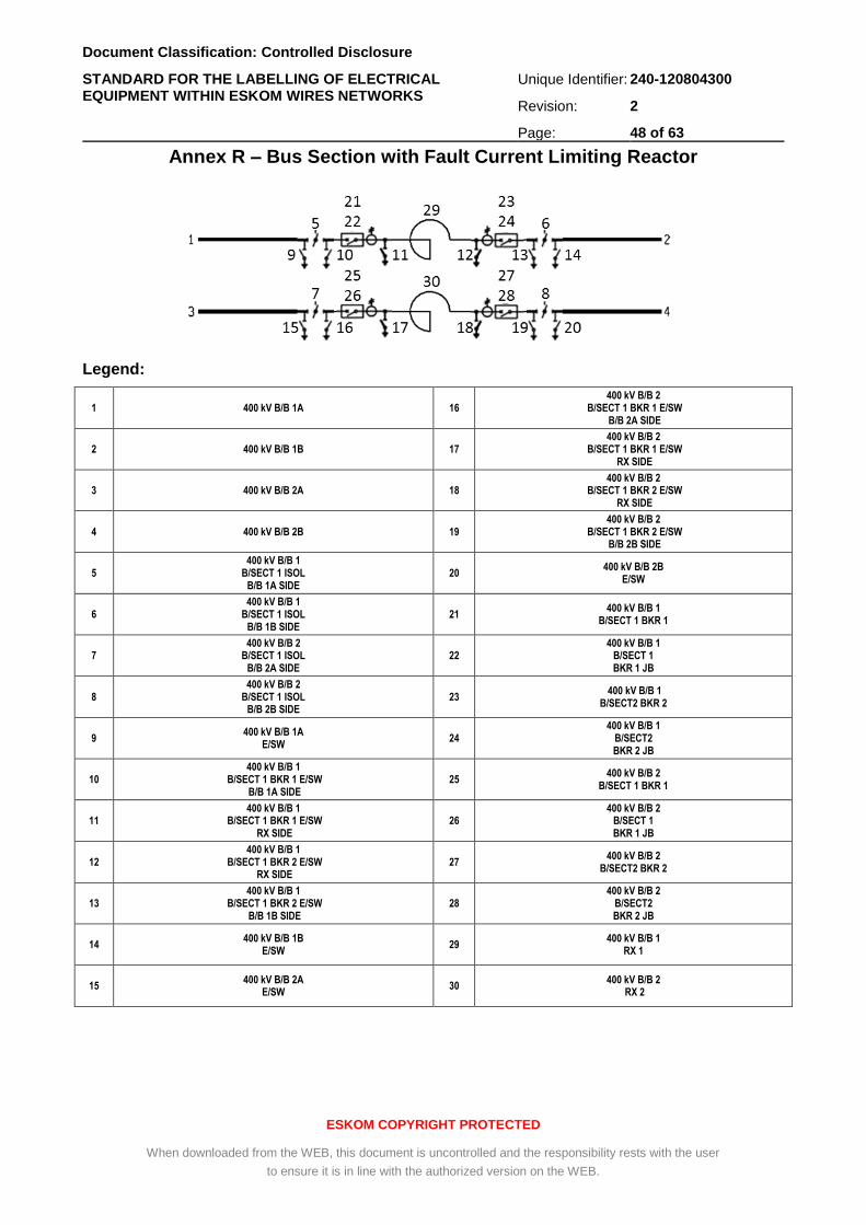
Document Classification: Controlled Disclosure
STANDARD FOR THE LABELLING OF ELECTRICAL EQUIPMENT WITHIN ESKOM WIRES NETWORKS
Unique Identifier: 240-120804300
Revision: 2
Page: 48 of 63
ESKOM COPYRIGHT PROTECTED
When downloaded from the WEB, this document is uncontrolled and the responsibility rests with the user
to ensure it is in line with the authorized version on the WEB.
Annex R – Bus Section with Fault Current Limiting Reactor
Legend:
1 400 kV B/B 1A 16 400 kV B/B 2
B/SECT 1 BKR 1 E/SW B/B 2A SIDE
2 400 kV B/B 1B 17 400 kV B/B 2
B/SECT 1 BKR 1 E/SW RX SIDE
3 400 kV B/B 2A 18 400 kV B/B 2
B/SECT 1 BKR 2 E/SW RX SIDE
4 400 kV B/B 2B 19 400 kV B/B 2
B/SECT 1 BKR 2 E/SW B/B 2B SIDE
5 400 kV B/B 1
B/SECT 1 ISOL B/B 1A SIDE
20 400 kV B/B 2B
E/SW
6 400 kV B/B 1
B/SECT 1 ISOL B/B 1B SIDE
21 400 kV B/B 1
B/SECT 1 BKR 1
7 400 kV B/B 2
B/SECT 1 ISOL B/B 2A SIDE
22 400 kV B/B 1
B/SECT 1 BKR 1 JB
8 400 kV B/B 2
B/SECT 1 ISOL B/B 2B SIDE
23 400 kV B/B 1
B/SECT2 BKR 2
9 400 kV B/B 1A
E/SW 24
400 kV B/B 1 B/SECT2 BKR 2 JB
10 400 kV B/B 1
B/SECT 1 BKR 1 E/SW B/B 1A SIDE
25 400 kV B/B 2
B/SECT 1 BKR 1
11 400 kV B/B 1
B/SECT 1 BKR 1 E/SW RX SIDE
26 400 kV B/B 2
B/SECT 1 BKR 1 JB
12 400 kV B/B 1
B/SECT 1 BKR 2 E/SW RX SIDE
27 400 kV B/B 2
B/SECT2 BKR 2
13 400 kV B/B 1
B/SECT 1 BKR 2 E/SW B/B 1B SIDE
28 400 kV B/B 2
B/SECT2 BKR 2 JB
14 400 kV B/B 1B
E/SW 29
400 kV B/B 1 RX 1
15 400 kV B/B 2A
E/SW 30
400 kV B/B 2 RX 2
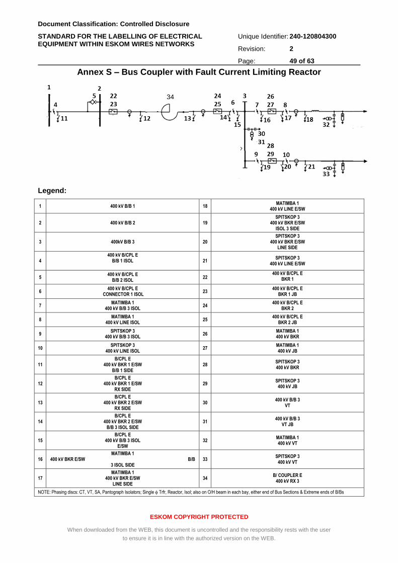
Document Classification: Controlled Disclosure
STANDARD FOR THE LABELLING OF ELECTRICAL EQUIPMENT WITHIN ESKOM WIRES NETWORKS
Unique Identifier: 240-120804300
Revision: 2
Page: 49 of 63
ESKOM COPYRIGHT PROTECTED
When downloaded from the WEB, this document is uncontrolled and the responsibility rests with the user
to ensure it is in line with the authorized version on the WEB.
Annex S – Bus Coupler with Fault Current Limiting Reactor
Legend:
1 400 kV B/B 1 18 MATIMBA 1
400 kV LINE E/SW
2 400 kV B/B 2 19 SPITSKOP 3
400 kV BKR E/SW ISOL 3 SIDE
3 400kV B/B 3 20 SPITSKOP 3
400 kV BKR E/SW LINE SIDE
4 400 kV B/CPL E
B/B 1 ISOL
21 SPITSKOP 3
400 kV LINE E/SW
5 400 kV B/CPL E
B/B 2 ISOL 22
400 kV B/CPL E BKR 1
6 400 kV B/CPL E
CONNECTOR 1 ISOL 23
400 kV B/CPL E BKR 1 JB
7 MATIMBA 1
400 kV B/B 3 ISOL 24
400 kV B/CPL E BKR 2
8 MATIMBA 1
400 kV LINE ISOL 25
400 kV B/CPL E BKR 2 JB
9 SPITSKOP 3
400 kV B/B 3 ISOL 26
MATIMBA 1 400 kV BKR
10 SPITSKOP 3
400 kV LINE ISOL 27
MATIMBA 1 400 kV JB
11 B/CPL E
400 kV BKR 1 E/SW B/B 1 SIDE
28 SPITSKOP 3 400 kV BKR
12 B/CPL E
400 kV BKR 1 E/SW RX SIDE
29 SPITSKOP 3
400 kV JB
13 B/CPL E
400 kV BKR 2 E/SW RX SIDE
30 400 kV B/B 3
VT
14 B/CPL E
400 kV BKR 2 E/SW B/B 3 ISOL SIDE
31 400 kV B/B 3
VT JB
15 B/CPL E
400 kV B/B 3 ISOL E/SW
32 MATIMBA 1 400 kV VT
16 MATIMBA 1
400 kV BKR E/SW B/B 3 ISOL SIDE
33 SPITSKOP 3
400 kV VT
17 MATIMBA 1
400 kV BKR E/SW LINE SIDE
34 B/ COUPLER E
400 kV RX 3
NOTE: Phasing discs: CT, VT, SA, Pantograph Isolators; Single Trfr, Reactor, Isol; also on O/H beam in each bay, either end of Bus Sections & Extreme ends of B/Bs
34
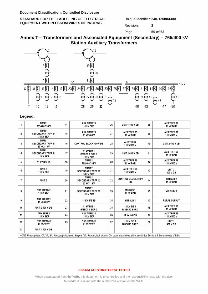
Document Classification: Controlled Disclosure
STANDARD FOR THE LABELLING OF ELECTRICAL EQUIPMENT WITHIN ESKOM WIRES NETWORKS
Unique Identifier: 240-120804300
Revision: 2
Page: 50 of 63
ESKOM COPYRIGHT PROTECTED
When downloaded from the WEB, this document is uncontrolled and the responsibility rests with the user
to ensure it is in line with the authorized version on the WEB.
Annex T – Transformers and Associated Equipment (Secondary) – 765/400 kV Station Auxiliary Transformers
Legend:
1 TRFR 1
765/400/33 kV 14
AUX TRFR 23 11 kV BKR
26 UNIT 1 400 V DB 38 AUX TRFR 27
11 kV BKR
2 TRFR 1
SECONDARY TRFR 11 33 kV BKR
15 AUX TRFR 23 11 kV/400 V
27 AUX TRFR 25
11 kV BKR 39
AUX TRFR 27 11 kV/400 V
3 TRFR 1
SECONDARY TRFR 11 33 kV/11 kV
16 CONTROL BLOCK 400 V DB 28 AUX TRFR2 11 kV/380 V
40 UNIT 2 400 V DB
4 TRFR 1
SECONDARY TRFR 11 11 kV BKR
17 11 kV B/B 1
B/SECT 1 BKR 1 11 kV BKR
29 UNIT 2 400 V DB 41 AUX TRFR 28
11 kV BKR
5 11 kV B/B 1A 18 TRFR 2
765/400/33 kV 30
AUX TRFR 26 11 kV BKR
42 AUX TRFR 28 11 kV/400 V
6 UNIT 3
11 kV BKR 19
TRFR 2 SECONDARY TRFR 12
33 kV BKR
31 AUX TRFR 26 11 kV/400 V
43 UNIT 3 400 V DB
7 UNIT 3 20 TRFR 2
SECONDARY TRFR 12 33 kV/11 kV
32 CONTROL BLOCK 400 V
DB 44
MINISUB 2 11 kV BKR
8 AUX TRFR 21
11 kV BKR 21
TRFR 2 SECONDARY TRFR 12
11 kV BKR 33
MINISUB1 11 kV BKR
45 MINISUB 2
9 AUX TRFR 21 11 kV/400 V
22 11 kV B/B 1B 34 MINISUB 1 47 RURAL SUPPLY
10 UNIT 3 400 V DB 23 11 kV B/B 1 B/SECT 1 BKR 2
11 kV BKR
35 11 kV B/B 1 B/SECT3 BKR 3
11 kV BKR
48 AUX TRFR 29
11 kV BKR
11 AUX TRFR2 11 kV BKR
24 AUX TRFR 24
11 kV BKR 36 11 kV B/B 1C 49
AUX TRFR 29 11 kV/400 V
12 AUX TRFR 22 11 kV/400 V
25 AUX TRFR 24 11 kV/400 V
37 11 kV B/B 1 B/SECT3 BKR 3
11 kV BKR
50 UNIT 1 400 V DB
13 UNIT 1 400 V DB
NOTE: Phasing discs: CT, VT, SA, Pantograph Isolators; Single Trfr, Reactor, Isol; also on O/H beam in each bay, either end of Bus Sections & Extreme ends of B/Bs
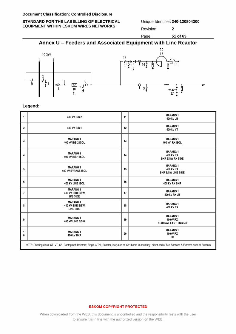
Document Classification: Controlled Disclosure
STANDARD FOR THE LABELLING OF ELECTRICAL EQUIPMENT WITHIN ESKOM WIRES NETWORKS
Unique Identifier: 240-120804300
Revision: 2
Page: 51 of 63
ESKOM COPYRIGHT PROTECTED
When downloaded from the WEB, this document is uncontrolled and the responsibility rests with the user
to ensure it is in line with the authorized version on the WEB.
Annex U – Feeders and Associated Equipment with Line Reactor
Legend:
1 400 kV B/B 2 11 MARANG 1 400 kV JB
2 400 kV B/B 1 12 MARANG 1 400 kV VT
3 MARANG 1
400 kV B/B 2 ISOL 13
MARANG 1 400 kV RX ISOL
4 MARANG 1
400 kV B/B 1 ISOL 14
MARANG 1 400 kV RX
BKR E/SW RX SIDE
5 MARANG 1
400 kV BYPASS ISOL 15
MARANG 1 400 kV RX
BKR E/SW LINE SIDE
6 MARANG 1
400 kV LINE ISOL 16
MARANG 1 400 kV RX BKR
7 MARANG 1
400 kV BKR E/SW B/B SIDE
17 MARANG 1
400 kV RX JB
8 MARANG 1
400 kV BKR E/SW LINE SIDE
18 MARANG 1 400 kV RX
9 MARANG 1
400 kV LINE E/SW 19
MARANG 1 400kV RX
NEUTRAL EARTHING RX
10
MARANG 1 400 kV BKR
20 MARANG 1 400kV RX
DB
NOTE: Phasing discs: CT, VT, SA, Pantograph Isolators; Single Trfr, Reactor, Isol; also on O/H beam in each bay, either end of Bus Sections & Extreme ends of Busbars
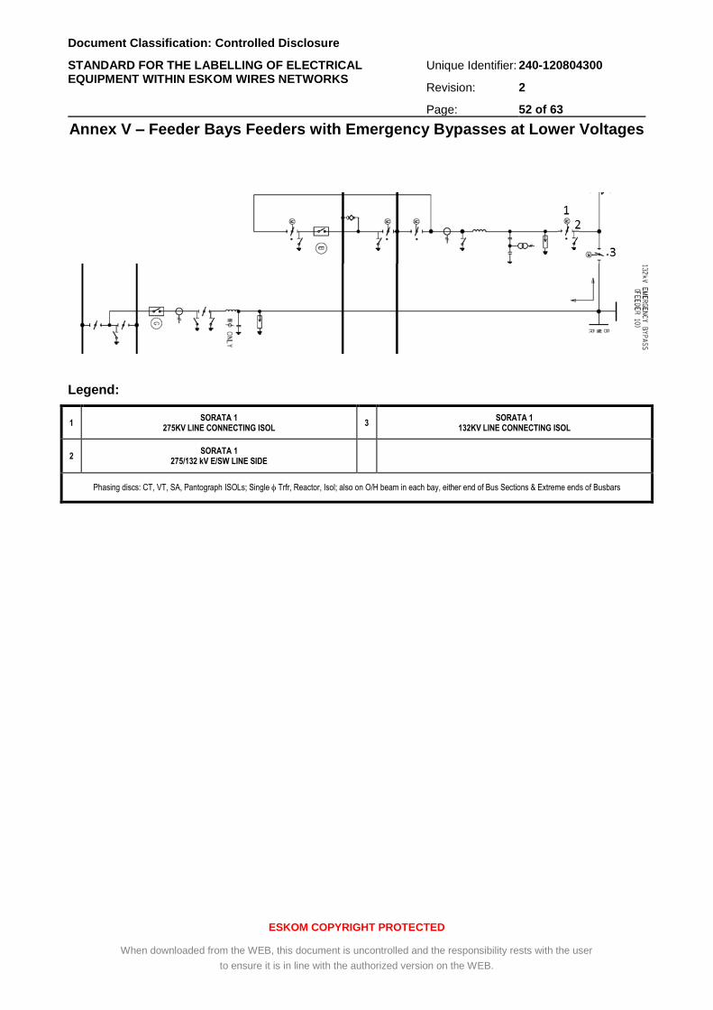
Document Classification: Controlled Disclosure
STANDARD FOR THE LABELLING OF ELECTRICAL EQUIPMENT WITHIN ESKOM WIRES NETWORKS
Unique Identifier: 240-120804300
Revision: 2
Page: 52 of 63
ESKOM COPYRIGHT PROTECTED
When downloaded from the WEB, this document is uncontrolled and the responsibility rests with the user
to ensure it is in line with the authorized version on the WEB.
Annex V – Feeder Bays Feeders with Emergency Bypasses at Lower Voltages
Legend:
1 SORATA 1
275KV LINE CONNECTING ISOL 3
SORATA 1 132KV LINE CONNECTING ISOL
2 SORATA 1
275/132 kV E/SW LINE SIDE
Phasing discs: CT, VT, SA, Pantograph ISOLs; Single Trfr, Reactor, Isol; also on O/H beam in each bay, either end of Bus Sections & Extreme ends of Busbars
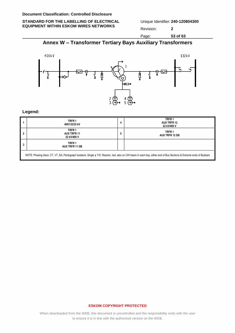
Document Classification: Controlled Disclosure
STANDARD FOR THE LABELLING OF ELECTRICAL EQUIPMENT WITHIN ESKOM WIRES NETWORKS
Unique Identifier: 240-120804300
Revision: 2
Page: 53 of 63
ESKOM COPYRIGHT PROTECTED
When downloaded from the WEB, this document is uncontrolled and the responsibility rests with the user
to ensure it is in line with the authorized version on the WEB.
Annex W – Transformer Tertiary Bays Auxiliary Transformers
Legend:
1 TRFR 1
400/132/22 kV 4
TRFR 1 AUX TRFR 12 22 kV/400 V
2 TRFR 1
AUX TRFR 11 22 kV/400 V
5 TRFR 1
AUX TRFR 12 DB
3 TRFR 1
AUX TRFR 11 DB
NOTE: Phasing discs: CT, VT, SA, Pantograph Isolators; Single Trfr, Reactor, Isol; also on O/H beam in each bay, either end of Bus Sections & Extreme ends of Busbars
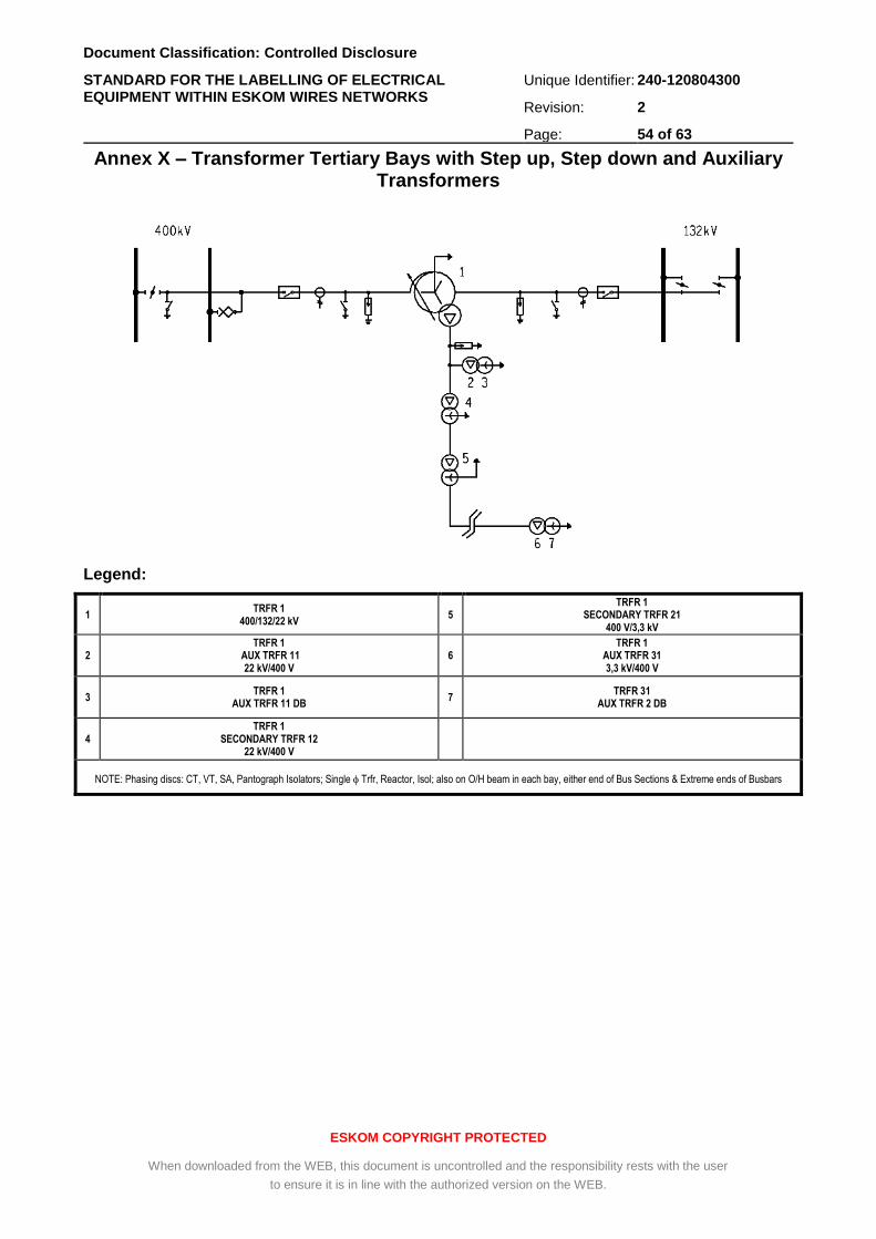
Document Classification: Controlled Disclosure
STANDARD FOR THE LABELLING OF ELECTRICAL EQUIPMENT WITHIN ESKOM WIRES NETWORKS
Unique Identifier: 240-120804300
Revision: 2
Page: 54 of 63
ESKOM COPYRIGHT PROTECTED
When downloaded from the WEB, this document is uncontrolled and the responsibility rests with the user
to ensure it is in line with the authorized version on the WEB.
Annex X – Transformer Tertiary Bays with Step up, Step down and Auxiliary Transformers
Legend:
1 TRFR 1
400/132/22 kV 5
TRFR 1 SECONDARY TRFR 21
400 V/3,3 kV
2 TRFR 1
AUX TRFR 11 22 kV/400 V
6 TRFR 1
AUX TRFR 31 3,3 kV/400 V
3 TRFR 1
AUX TRFR 11 DB 7
TRFR 31 AUX TRFR 2 DB
4 TRFR 1
SECONDARY TRFR 12 22 kV/400 V
NOTE: Phasing discs: CT, VT, SA, Pantograph Isolators; Single Trfr, Reactor, Isol; also on O/H beam in each bay, either end of Bus Sections & Extreme ends of Busbars
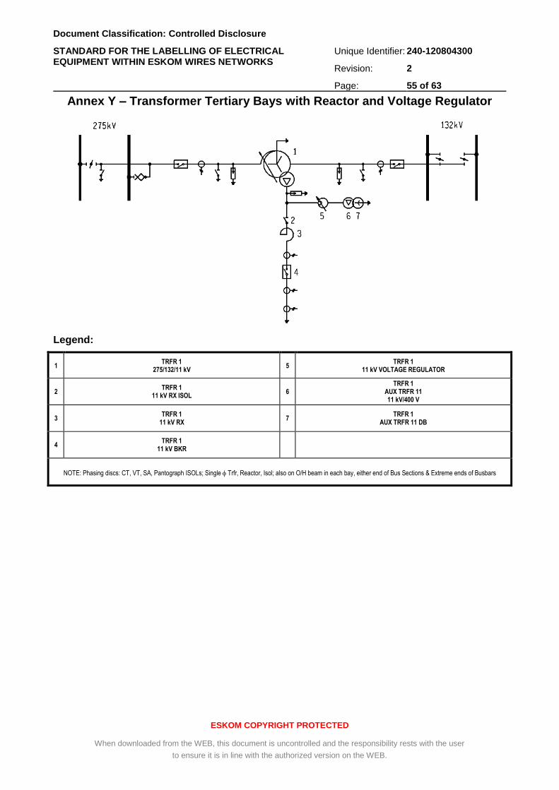
Document Classification: Controlled Disclosure
STANDARD FOR THE LABELLING OF ELECTRICAL EQUIPMENT WITHIN ESKOM WIRES NETWORKS
Unique Identifier: 240-120804300
Revision: 2
Page: 55 of 63
ESKOM COPYRIGHT PROTECTED
When downloaded from the WEB, this document is uncontrolled and the responsibility rests with the user
to ensure it is in line with the authorized version on the WEB.
Annex Y – Transformer Tertiary Bays with Reactor and Voltage Regulator
Legend:
1 TRFR 1
275/132/11 kV 5
TRFR 1 11 kV VOLTAGE REGULATOR
2 TRFR 1
11 kV RX ISOL 6
TRFR 1 AUX TRFR 11 11 kV/400 V
3 TRFR 1
11 kV RX 7
TRFR 1 AUX TRFR 11 DB
4 TRFR 1
11 kV BKR
NOTE: Phasing discs: CT, VT, SA, Pantograph ISOLs; Single Trfr, Reactor, Isol; also on O/H beam in each bay, either end of Bus Sections & Extreme ends of Busbars
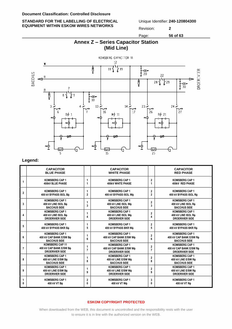
Document Classification: Controlled Disclosure
STANDARD FOR THE LABELLING OF ELECTRICAL EQUIPMENT WITHIN ESKOM WIRES NETWORKS
Unique Identifier: 240-120804300
Revision: 2
Page: 56 of 63
ESKOM COPYRIGHT PROTECTED
When downloaded from the WEB, this document is uncontrolled and the responsibility rests with the user
to ensure it is in line with the authorized version on the WEB.
Annex Z – Series Capacitor Station (Mid Line)
Legend:
CAPACITOR BLUE PHASE
CAPACITOR
WHITE PHASE
CAPACITOR RED PHASE
1 KOMSBERG CAP 1 400kV BLUE PHASE
11
KOMSBERG CAP 1 400kV WHITE PHASE
21
KOMSBERG CAP 1 400kV RED PHASE
2 KOMSBERG CAP 1
400 kV BYPASS ISOL B 12
KOMSBERG CAP 1
400 kV BYPASS ISOL W 22
KOMSBERG CAP 1
400 kV BYPASS ISOL R
3
KOMSBERG CAP 1
400 kV LINE ISOL B BACCHUS SIDE
13
KOMSBERG CAP 1
400 kV LINE ISOL W BACCHUS SIDE
23
KOMSBERG CAP 1
400 kV LINE ISOL R BACCHUS SIDE
4
KOMSBERG CAP 1
400 kV LINE ISOL B DROERIVIER SIDE
14
KOMSBERG CAP 1
400 kV LINE ISOL W DROERIVIER SIDE
24
KOMSBERG CAP 1
400 kV LINE ISOL R DROERIVIER SIDE
5 KOMSBERG CAP 1
400 kV BYPASS BKR B
15
KOMSBERG CAP 1
400 kV BYPASS BKR W
25
KOMSBERG CAP 1
400 kV BYPASS BKR R
6
KOMSBERG CAP 1
400 kV CAP BANK E/SW B BACCHUS SIDE
16
KOMSBERG CAP 1
400 kV CAP BANK E/SW W BACCHUS SIDE
26
KOMSBERG CAP 1
400 kV CAP BANK E/SW R BACCHUS SIDE
7
KOMSBERG CAP 11
400 kV CAP BANK E/SW B DROERIVIER SIDE
17
KOMSBERG CAP 1
400 kV CAP BANK E/SW W DROERIVIER SIDE
27
KOMSBERG CAP 1
400 kV CAP BANK E/SW R DROERIVIER SIDE
8
KOMSBERG CAP 1
400 kV LINE E/SW B BACCHUS SIDE
18
KOMSBERG CAP 1
400 kV LINE E/SW W BACCHUS SIDE
28
KOMSBERG CAP 1
400 kV LINE E/SW R BACCHUS SIDE
9
KOMSBERG CAP 1
400 kV LINE E/SW B DROERIVIER SIDE
19
KOMSBERG CAP 1
400 kV LINE E/SW W DROERIVIER SIDE
29
KOMSBERG CAP 1
400 kV LINE E/SW R DROERIVIER SIDE
10
KOMSBERG CAP 1
400 kV VT B 20
KOMSBERG CAP 1
400 kV VT W 30
KOMSBERG CAP 1
400 kV VT R
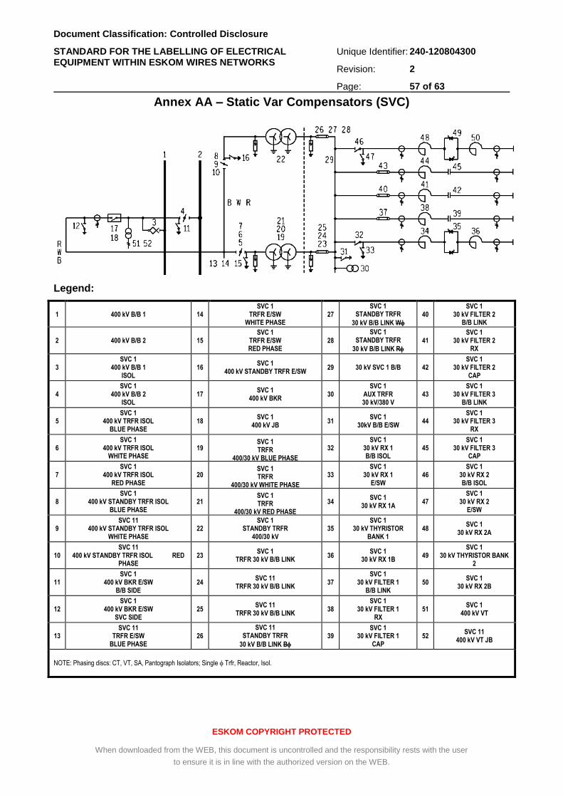
Document Classification: Controlled Disclosure
STANDARD FOR THE LABELLING OF ELECTRICAL EQUIPMENT WITHIN ESKOM WIRES NETWORKS
Unique Identifier: 240-120804300
Revision: 2
Page: 57 of 63
ESKOM COPYRIGHT PROTECTED
When downloaded from the WEB, this document is uncontrolled and the responsibility rests with the user
to ensure it is in line with the authorized version on the WEB.
Annex AA – Static Var Compensators (SVC)
Legend:
1 400 kV B/B 1 14 SVC 1
TRFR E/SW WHITE PHASE
27 SVC 1
STANDBY TRFR
30 kV B/B LINK W
40 SVC 1
30 kV FILTER 2 B/B LINK
2 400 kV B/B 2 15 SVC 1
TRFR E/SW RED PHASE
28
SVC 1 STANDBY TRFR
30 kV B/B LINK R 41
SVC 1 30 kV FILTER 2
RX
3 SVC 1
400 kV B/B 1 ISOL
16 SVC 1
400 kV STANDBY TRFR E/SW 29 30 kV SVC 1 B/B 42
SVC 1 30 kV FILTER 2
CAP
4 SVC 1
400 kV B/B 2 ISOL
17 SVC 1
400 kV BKR 30
SVC 1 AUX TRFR 30 kV/380 V
43 SVC 1
30 kV FILTER 3 B/B LINK
5 SVC 1
400 kV TRFR ISOL BLUE PHASE
18 SVC 1
400 kV JB 31
SVC 1 30kV B/B E/SW
44 SVC 1
30 kV FILTER 3 RX
6 SVC 1
400 kV TRFR ISOL WHITE PHASE
19 SVC 1 TRFR
400/30 kV BLUE PHASE
32 SVC 1
30 kV RX 1 B/B ISOL
45 SVC 1
30 kV FILTER 3 CAP
7 SVC 1
400 kV TRFR ISOL RED PHASE
20 SVC 1 TRFR
400/30 kV WHITE PHASE
33 SVC 1
30 kV RX 1 E/SW
46 SVC 1
30 kV RX 2 B/B ISOL
8 SVC 1
400 kV STANDBY TRFR ISOL BLUE PHASE
21 SVC 1 TRFR
400/30 kV RED PHASE
34 SVC 1
30 kV RX 1A 47
SVC 1 30 kV RX 2
E/SW
9 SVC 11
400 kV STANDBY TRFR ISOL WHITE PHASE
22 SVC 1
STANDBY TRFR 400/30 kV
35 SVC 1
30 kV THYRISTOR BANK 1
48 SVC 1
30 kV RX 2A
10 SVC 11
400 kV STANDBY TRFR ISOL RED PHASE
23 SVC 1
TRFR 30 kV B/B LINK 36
SVC 1 30 kV RX 1B
49 SVC 1
30 kV THYRISTOR BANK 2
11 SVC 1
400 kV BKR E/SW B/B SIDE
24 SVC 11
TRFR 30 kV B/B LINK 37
SVC 1 30 kV FILTER 1
B/B LINK 50
SVC 1 30 kV RX 2B
12 SVC 1
400 kV BKR E/SW SVC SIDE
25 SVC 11
TRFR 30 kV B/B LINK 38
SVC 1 30 kV FILTER 1
RX 51
SVC 1 400 kV VT
13 SVC 11
TRFR E/SW BLUE PHASE
26
SVC 11 STANDBY TRFR
30 kV B/B LINK B
39 SVC 1
30 kV FILTER 1 CAP
52 SVC 11
400 kV VT JB
NOTE: Phasing discs: CT, VT, SA, Pantograph Isolators; Single Trfr, Reactor, Isol.
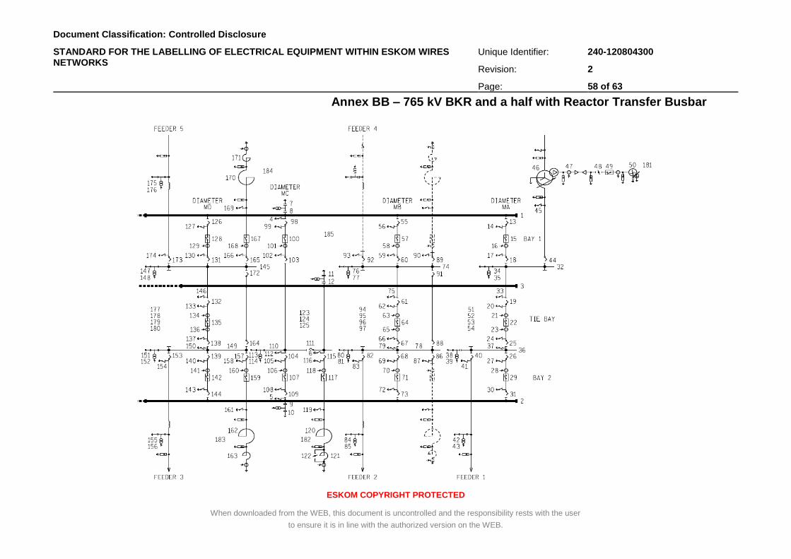
Document Classification: Controlled Disclosure
STANDARD FOR THE LABELLING OF ELECTRICAL EQUIPMENT WITHIN ESKOM WIRES NETWORKS
Unique Identifier: 240-120804300
Revision: 2
Page: 58 of 63
ESKOM COPYRIGHT PROTECTED
When downloaded from the WEB, this document is uncontrolled and the responsibility rests with the user
to ensure it is in line with the authorized version on the WEB.
Annex BB – 765 kV BKR and a half with Reactor Transfer Busbar
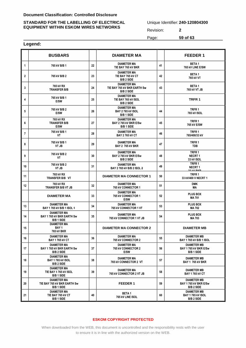
Document Classification: Controlled Disclosure
STANDARD FOR THE LABELLING OF ELECTRICAL EQUIPMENT WITHIN ESKOM WIRES NETWORKS
Unique Identifier: 240-120804300
Revision: 2
Page: 59 of 63
ESKOM COPYRIGHT PROTECTED
When downloaded from the WEB, this document is uncontrolled and the responsibility rests with the user
to ensure it is in line with the authorized version on the WEB.
Legend:
BUSBARS DIAMETER MA FEEDER 1
1 765 kV B/B 1 22 DIAMETER MA
TIE BAY 765 kV BKR 41
BETA 1 765 kV LINE E/SW
2 765 kV B/B 2 23 DIAMETER MA
TIE BAY 765 kV CT B/B 2 SIDE
42 BETA 1
765 kV VT
3 765 kV RX
TRANSFER B/B 24
DIAMETER MA TIE BAY 765 kV BKR EARTH Sw
B/B 2 SIDE 43
BETA 1 765 kV VT JB
4 765 kV B/B 1
E/SW 25
DIAMETER MA TIE BAY 765 kV ISOL
B/B 2 SIDE TRFR 1
5 765 kV B/B 2
E/SW 26
DIAMETER MA BAY 2 765 kV ISOL
B/B 1 SIDE 44
TRFR 1 765 kV ISOL
6 765 kV RX
TRANSFER B/B E/SW
27 DIAMETER MA
BAY 2 765 kV BKR E/Sw B/B 1 SIDE
45 TRFR 1
765 kV E/SW
7 765 kV B/B 1
VT 28
DIAMETER MA BAY 2 765 kV CT
46 TRFR 1
765/400/33 kV
8 765 kV B/B 1
VT JB 29
DIAMETER MA BAY 2 765 kV BKR
47 TRFR 1
TDB
9 765 kV B/B 2
VT 30
DIAMETER MA BAY 2 765 kV BKR E/Sw
B/B 2 SIDE 48
TRFR 1 NECRT 1
33 kV ISOL
10 765 kV B/B 2
VT JB 31
DIAMETER MA BAY 2 765 kV B/B 2 ISOL 2
49 TRFR 1
NECRT 1 33 kV BKR
11 765 kV RX
TRANSFER B/B VT DIAMETER MA CONNECTOR 1 50
TRFR 1 33 kV/400 V NECRT 1
12 765 kV RX
TRANSFER B/B VT JB 32
DIAMETER MA 765 kV CONNECTOR 1
51 DMK MA
DIAMETER MA 33 DIAMETER MA
765 kV CONNECTOR 1 E/SW
52 PLUG BOX
MA 701
13 DIAMETER MA
BAY 1 765 kV B/B 1 ISOL 1 34
DIAMETER MA 765 kV CONNECTOR 1 VT
53 PLUG BOX
MA 702
14 DIAMETER MA
BAY 1 765 kV BKR EARTH Sw B/B 1 SIDE
35 DIAMETER MA
765 kV CONNECTOR 1 VT JB 54
PLUG BOX MA 703
15
DIAMETER MA BAY 1
765 kV BKR
DIAMETER MA CONNECTOR 2 DIAMETER MB
16 DIAMETER MA
BAY 1 765 kV CT 36
DIAMETER MA 765 kV CONNECTOR 2
55 DIAMETER MB
BAY 1 765 kV B/B 1 ISOL
17 DIAMETER MA
BAY 1 765 kV BKR EARTH Sw B/B 2 SIDE
37 DIAMETER MA
765 kV CONNECTOR 2 E/SW
56 DIAMETER MB
BAY 1 765 kV BKR E/Sw B/B 1 SIDE
18 DIAMETER MA
BAY 1 765 kV ISOL B/B 2 SIDE
38 DIAMETER MA
765 kV CONNECTOR 2 VT 57
DIAMETER MB BAY 1 765 kV BKR
19 DIAMETER MA
TIE BAY 1 765 kV ISOL B/B 1 SIDE
39 DIAMETER MA
765 kV CONNECTOR 2 VT JB 58
DIAMETER MB BAY 1 765 kV CT
20 DIAMETER MA
TIE BAY 765 kV BKR EARTH Sw B/B 1 SIDE
FEEDER 1 59 DIAMETER MB
BAY 1 765 kV BKR E/Sw B/B 2 SIDE
21 DIAMETER MA
TIE BAY 765 kV CT B/B 1 SIDE
40 BETA 1
765 kV LINE ISOL 60
DIAMETER MB BAY 1 765 kV ISOL
B/B 2 SIDE
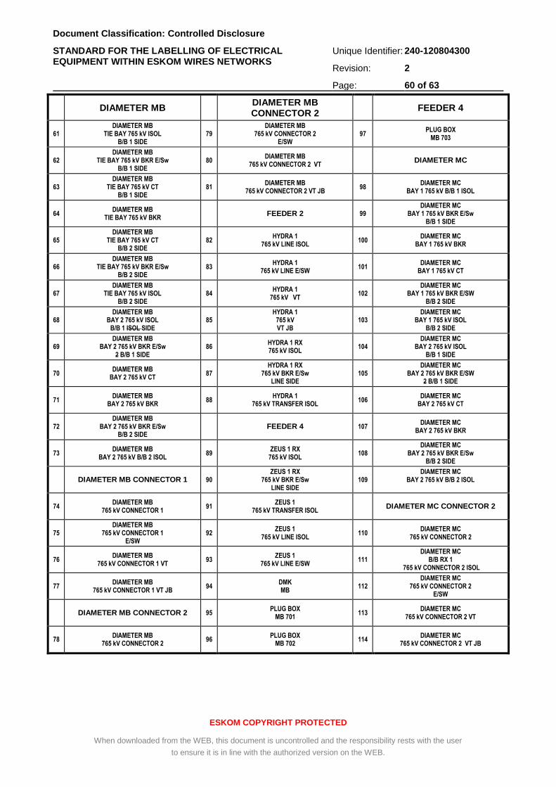
Document Classification: Controlled Disclosure
STANDARD FOR THE LABELLING OF ELECTRICAL EQUIPMENT WITHIN ESKOM WIRES NETWORKS
Unique Identifier: 240-120804300
Revision: 2
Page: 60 of 63
ESKOM COPYRIGHT PROTECTED
When downloaded from the WEB, this document is uncontrolled and the responsibility rests with the user
to ensure it is in line with the authorized version on the WEB.
DIAMETER MB DIAMETER MB CONNECTOR 2
FEEDER 4
61 DIAMETER MB
TIE BAY 765 kV ISOL B/B 1 SIDE
79 DIAMETER MB
765 kV CONNECTOR 2 E/SW
97 PLUG BOX
MB 703
62 DIAMETER MB
TIE BAY 765 kV BKR E/Sw B/B 1 SIDE
80 DIAMETER MB
765 kV CONNECTOR 2 VT DIAMETER MC
63 DIAMETER MB
TIE BAY 765 kV CT B/B 1 SIDE
81 DIAMETER MB
765 kV CONNECTOR 2 VT JB 98
DIAMETER MC BAY 1 765 kV B/B 1 ISOL
64 DIAMETER MB
TIE BAY 765 kV BKR FEEDER 2 99
DIAMETER MC BAY 1 765 kV BKR E/Sw
B/B 1 SIDE
65 DIAMETER MB
TIE BAY 765 kV CT B/B 2 SIDE
82 HYDRA 1
765 kV LINE ISOL 100
DIAMETER MC BAY 1 765 kV BKR
66 DIAMETER MB
TIE BAY 765 kV BKR E/Sw B/B 2 SIDE
83 HYDRA 1
765 kV LINE E/SW 101
DIAMETER MC BAY 1 765 kV CT
67 DIAMETER MB
TIE BAY 765 kV ISOL B/B 2 SIDE
84 HYDRA 1
765 kV VT 102
DIAMETER MC BAY 1 765 kV BKR E/SW
B/B 2 SIDE
68 DIAMETER MB
BAY 2 765 kV ISOL B/B 1 ISOL SIDE
85 HYDRA 1
765 kV VT JB
103 DIAMETER MC
BAY 1 765 kV ISOL B/B 2 SIDE
69 DIAMETER MB
BAY 2 765 kV BKR E/Sw 2 B/B 1 SIDE
86 HYDRA 1 RX 765 kV ISOL
104 DIAMETER MC
BAY 2 765 kV ISOL B/B 1 SIDE
70 DIAMETER MB
BAY 2 765 kV CT 87
HYDRA 1 RX 765 kV BKR E/Sw
LINE SIDE 105
DIAMETER MC BAY 2 765 kV BKR E/SW
2 B/B 1 SIDE
71 DIAMETER MB
BAY 2 765 kV BKR 88
HYDRA 1 765 kV TRANSFER ISOL
106 DIAMETER MC
BAY 2 765 kV CT
72 DIAMETER MB
BAY 2 765 kV BKR E/Sw B/B 2 SIDE
FEEDER 4 107 DIAMETER MC
BAY 2 765 kV BKR
73 DIAMETER MB
BAY 2 765 kV B/B 2 ISOL 89
ZEUS 1 RX 765 kV ISOL
108 DIAMETER MC
BAY 2 765 kV BKR E/Sw B/B 2 SIDE
DIAMETER MB CONNECTOR 1 90 ZEUS 1 RX
765 kV BKR E/Sw LINE SIDE
109 DIAMETER MC
BAY 2 765 kV B/B 2 ISOL
74 DIAMETER MB
765 kV CONNECTOR 1 91
ZEUS 1 765 kV TRANSFER ISOL
DIAMETER MC CONNECTOR 2
75 DIAMETER MB
765 kV CONNECTOR 1 E/SW
92 ZEUS 1
765 kV LINE ISOL 110
DIAMETER MC 765 kV CONNECTOR 2
76 DIAMETER MB
765 kV CONNECTOR 1 VT 93
ZEUS 1 765 kV LINE E/SW
111 DIAMETER MC
B/B RX 1 765 kV CONNECTOR 2 ISOL
77 DIAMETER MB
765 kV CONNECTOR 1 VT JB 94
DMK MB
112 DIAMETER MC
765 kV CONNECTOR 2 E/SW
DIAMETER MB CONNECTOR 2 95 PLUG BOX
MB 701 113
DIAMETER MC 765 kV CONNECTOR 2 VT
78 DIAMETER MB
765 kV CONNECTOR 2 96
PLUG BOX MB 702
114 DIAMETER MC
765 kV CONNECTOR 2 VT JB
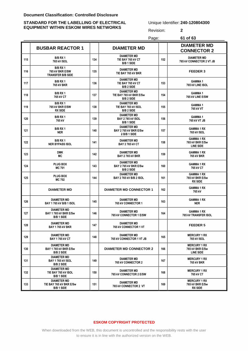
Document Classification: Controlled Disclosure
STANDARD FOR THE LABELLING OF ELECTRICAL EQUIPMENT WITHIN ESKOM WIRES NETWORKS
Unique Identifier: 240-120804300
Revision: 2
Page: 61 of 63
ESKOM COPYRIGHT PROTECTED
When downloaded from the WEB, this document is uncontrolled and the responsibility rests with the user
to ensure it is in line with the authorized version on the WEB.
BUSBAR REACTOR 1 DIAMETER MD DIAMETER MD CONNECTOR 2
115 B/B RX 1
765 kV ISOL 134
DIAMETER MD TIE BAY 765 kV CT
B/B 1 SIDE 152
DIAMETER MD 765 kV CONNECTOR 2 VT JB
116 B/B RX 1
765 kV BKR E/SW TRANSFER B/B SIDE
135 DIAMETER MD
TIE BAY 765 kV BKR FEEDER 3
117 B/B RX 1
765 kV BKR 136
DIAMETER MD TIE BAY 765 kV CT
B/B 2 SIDE 153
GAMMA 1 765 kV LINE ISOL
118 B/B RX 1
765 kV CT 137
DIAMETER MD TIE BAY 765 kV BKR E/Sw
B/B 2 SIDE 154
GAMMA 1 765 kV LINE E/SW
119 B/B RX 1
765 kV BKR E/SW RX SIDE
138 DIAMETER MD
TIE BAY 765 kV ISOL B/B 2 SIDE
155 GAMMA 1 765 kV VT
120 B/B RX 1 765 kV
139 DIAMETER MD
BAY 2 765 kV ISOL B/B 1 SIDE
156 GAMMA 1
765 kV VT JB
121 B/B RX 1
NER 140
DIAMETER MD BAY 2 765 kV BKR E/Sw
2 B/B 1 SIDE 157
GAMMA 1 RX 765 kV ISOL
122 B/B RX 1
NER BYPASS ISOL 141
DIAMETER MD BAY 2 765 kV CT
158 GAMMA 1 RX
765 kV BKR E/Sw LINE SIDE
123 DMK MC
142 DIAMETER MD
BAY 2 765 kV BKR 159
GAMMA 1 RX 765 kV BKR
124 PLUG BOX
MC 701 143
DIAMETER MD BAY 2 765 kV BKR E/Sw
B/B 2 SIDE 160
GAMMA 1 RX 765 kV CT
125 PLUG BOX
MC 702 144
DIAMETER MD BAY 2 765 kV B/B 2 ISOL
161
GAMMA 1 RX 765 kV BKR E/Sw
RX SIDE
DIAMETER MD DIAMETER MD CONNECTOR 1 162 GAMMA 1 RX
765 kV
126 DIAMETER MD
BAY 1 765 kV B/B 1 ISOL 145
DIAMETER MD 765 kV CONNECTOR 1
163 GAMMA 1 RX
NER
127 DIAMETER MD
BAY 1 765 kV BKR E/Sw B/B 1 SIDE
146 DIAMETER MD
765 kV CONNECTOR 1 E/SW 164
GAMMA 1 RX 765 kV TRANSFER ISOL
128 DIAMETER MD
BAY 1 765 kV BKR 147
DIAMETER MD 765 kV CONNECTOR 1 VT
FEEDER 5
129 DIAMETER MD
BAY 1 765 kV CT 148
DIAMETER MD 765 kV CONNECTOR 1 VT JB
165 MERCURY 1 RX
765 kV ISOL
130 DIAMETER MD
BAY 1 765 kV BKR E/Sw B/B 2 SIDE
DIAMETER MD CONNECTOR 2 166 MERCURY 1 RX
765 kV BKR E/Sw LINE SIDE
131 DIAMETER MD
BAY 1 765 kV ISOL B/B 2 SIDE
149 DIAMETER MD
765 kV CONNECTOR 2 167
MERCURY 1 RX 765 kV BKR
132 DIAMETER MD
TIE BAY 765 kV ISOL B/B 1 SIDE
150 DIAMETER MD
765 kV CONNECTOR 2 E/SW 168
MERCURY 1 RX 765 kV CT
133 DIAMETER MD
TIE BAY 765 kV BKR E/Sw B/B 1 SIDE
151 DIAMETER MD
765 kV CONNECTOR 2 VT 169
MERCURY 1 RX 765 kV BKR E/Sw
RX SIDE
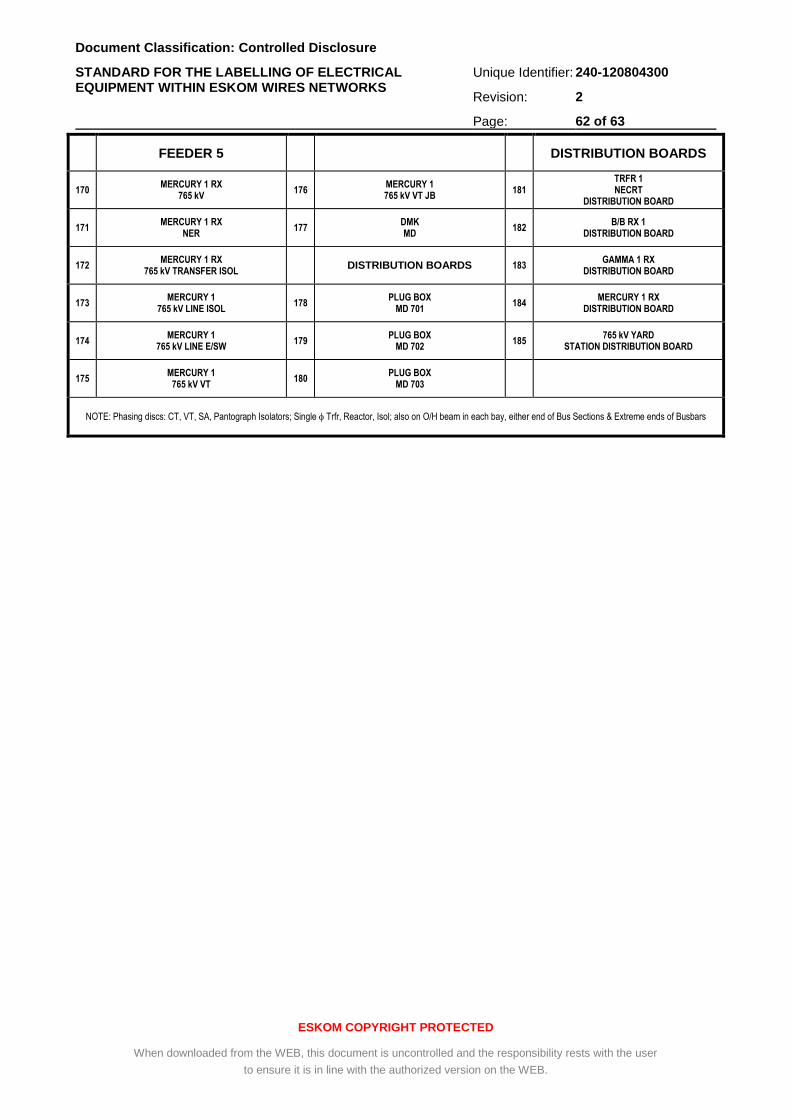
Document Classification: Controlled Disclosure
STANDARD FOR THE LABELLING OF ELECTRICAL EQUIPMENT WITHIN ESKOM WIRES NETWORKS
Unique Identifier: 240-120804300
Revision: 2
Page: 62 of 63
ESKOM COPYRIGHT PROTECTED
When downloaded from the WEB, this document is uncontrolled and the responsibility rests with the user
to ensure it is in line with the authorized version on the WEB.
FEEDER 5 DISTRIBUTION BOARDS
170 MERCURY 1 RX
765 kV 176
MERCURY 1 765 kV VT JB
181 TRFR 1 NECRT
DISTRIBUTION BOARD
171 MERCURY 1 RX
NER 177
DMK MD
182 B/B RX 1
DISTRIBUTION BOARD
172 MERCURY 1 RX
765 kV TRANSFER ISOL DISTRIBUTION BOARDS 183
GAMMA 1 RX DISTRIBUTION BOARD
173 MERCURY 1
765 kV LINE ISOL 178
PLUG BOX MD 701
184 MERCURY 1 RX
DISTRIBUTION BOARD
174 MERCURY 1
765 kV LINE E/SW 179
PLUG BOX MD 702
185 765 kV YARD
STATION DISTRIBUTION BOARD
175 MERCURY 1
765 kV VT 180
PLUG BOX MD 703
NOTE: Phasing discs: CT, VT, SA, Pantograph Isolators; Single Trfr, Reactor, Isol; also on O/H beam in each bay, either end of Bus Sections & Extreme ends of Busbars
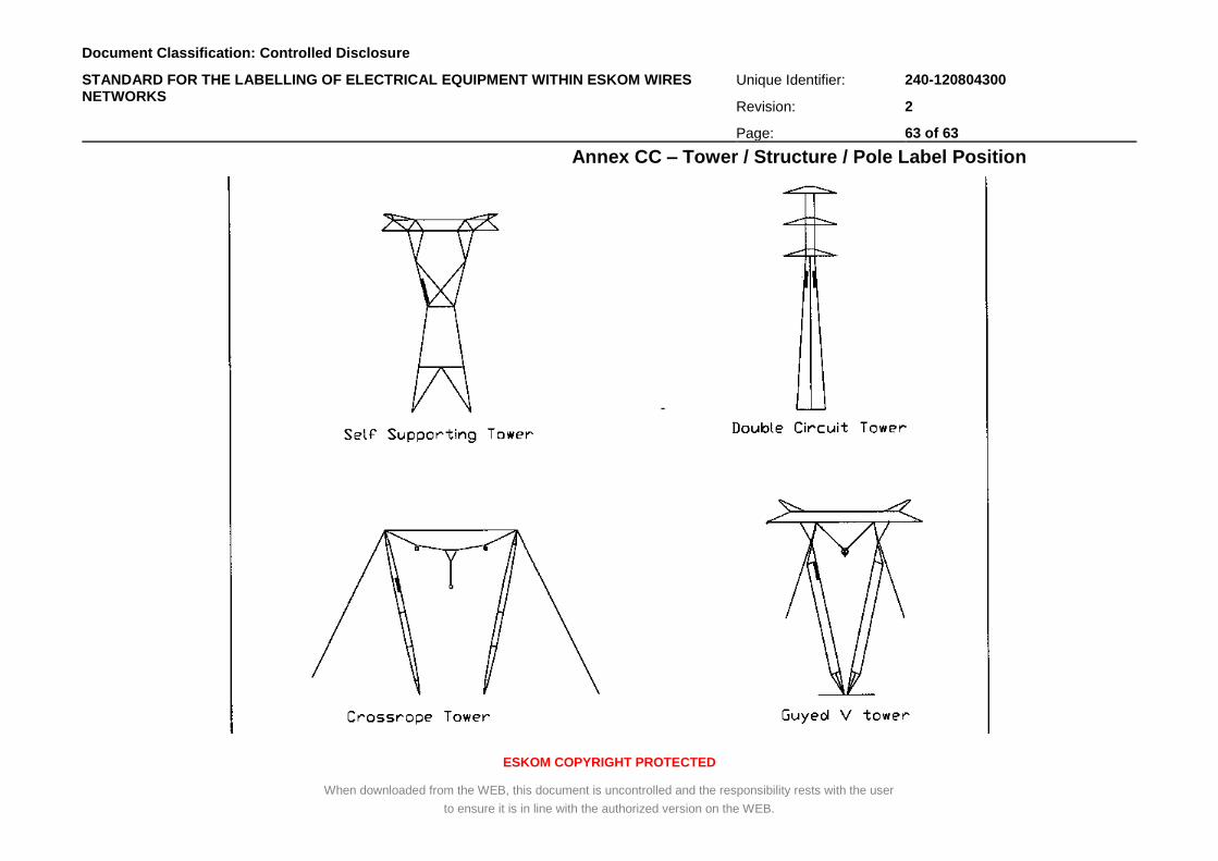
Document Classification: Controlled Disclosure
STANDARD FOR THE LABELLING OF ELECTRICAL EQUIPMENT WITHIN ESKOM WIRES NETWORKS
Unique Identifier: 240-120804300
Revision: 2
Page: 63 of 63
ESKOM COPYRIGHT PROTECTED
When downloaded from the WEB, this document is uncontrolled and the responsibility rests with the user
to ensure it is in line with the authorized version on the WEB.
Annex CC – Tower / Structure / Pole Label Position
![Standard Technology Title: SPECIFICATION FOR Unique ... AB schedule... · 3.10.1 Routine Factory tests ... Power transformers – Part 11: Dry-type transformers [9] ... terminology](https://img.pdfslide.us/doc/110x75/5ad061647f8b9a1d328e3b2b/standard-technology-title-specification-for-unique-ab-schedule3101-routine.jpg)


![Standard Technology Title: SPECIFICATION FOR Unique ... 240... · [3] ASTM B918/B918M, Standard Practice for Heat Treatment of Wrought Aluminum Alloys. [4] BS 159, Specification for](https://img.pdfslide.us/doc/110x75/5e149cd329a04949234cfeb7/standard-technology-title-specification-for-unique-240-3-astm-b918b918m.jpg)