Embed Size (px)
Citation preview

ESE00202-EN7 2013-12
Original manual
Instruction Manual
Unique Single Seat Valve - Standard and Reverse Acting


Table of contents
The information herein is correct at the time of issue but may be subject to change without prior notice
1. EC Declaration of Conformity .. . . . . . . . . . . . . . . . . . . . . . . . . . . . . . . . . . . . . . . . . . . . . . . . . . . . . . . . . . . . . . . . . . . . . . 4
2. Safety ... . . . . . . . . . . . . . . . . . . . . . . . . . . . . . . . . . . . . . . . . . . . . . . . . . . . . . . . . . . . . . . . . . . . . . . . . . . . . . . . . . . . . . . . . . . . . . . . . . 52.1. Important information .. . . . . . . . . . . . . . . . . . . . . . . . . . . . . . . . . . . . . . . . . . . . . . . . . . . . . . . . . . . . . . . . . . . . . . . . . . . . 52.2. Warning signs .. .. . . . . . . . . . . . . . . . . . . . . . . . . . . . . . . . . . . . . . . . . . . . . . . . . . . . . . . . . . . . . . . . . . . . . . . . . . . . . . . . . . 52.3. Safety precautions .. . .. . . . . . . . . . . . . . . . . . . . . . . . . . . . . . . . . . . . . . . . . . . . . . . . . . . . . . . . . . . . . . . . . . . . . . . . . . . . 6
3. Installation .. . . . . . . . . . . . . . . . . . . . . . . . . . . . . . . . . . . . . . . . . . . . . . . . . . . . . . . . . . . . . . . . . . . . . . . . . . . . . . . . . . . . . . . . . . . . . 83.1. Unpacking/delivery . . .. . . . . . . . . . . . . . . . . . . . . . . . . . . . . . . . . . . . . . . . . . . . . . . . . . . . . . . . . . . . . . . . . . . . . . . . . . . . 83.2. General installation .. . .. . . . . . . . . . . . . . . . . . . . . . . . . . . . . . . . . . . . . . . . . . . . . . . . . . . . . . . . . . . . . . . . . . . . . . . . . . . . 103.3. Welding .. . . . . . . . . . . . . . . . . . . . . . . . . . . . . . . . . . . . . . . . . . . . . . . . . . . . . . . . . . . . . . . . . . . . . . . . . . . . . . . . . . . . . . . . . . . 113.4. Recycling information .. . . . . . . . . . . . . . . . . . . . . . . . . . . . . . . . . . . . . . . . . . . . . . . . . . . . . . . . . . . . . . . . . . . . . . . . . . . . 12
4. Operation ... . . . . . . . . . . . . . . . . . . . . . . . . . . . . . . . . . . . . . . . . . . . . . . . . . . . . . . . . . . . . . . . . . . . . . . . . . . . . . . . . . . . . . . . . . . . . 134.1. Operation .. .. . . . . . . . . . . . . . . . . . . . . . . . . . . . . . . . . . . . . . . . . . . . . . . . . . . . . . . . . . . . . . . . . . . . . . . . . . . . . . . . . . . . . . . 134.2. Troubleshooting .. . . . . . . . . . . . . . . . . . . . . . . . . . . . . . . . . . . . . . . . . . . . . . . . . . . . . . . . . . . . . . . . . . . . . . . . . . . . . . . . . . 144.3. Recommended cleaning ... . . . . . . . . . . . . . . . . . . . . . . . . . . . . . . . . . . . . . . . . . . . . . . . . . . . . . . . . . . . . . . . . . . . . . . 15
5. Maintenance .. . .. . . . . . . . . . . . . . . . . . . . . . . . . . . . . . . . . . . . . . . . . . . . . . . . . . . . . . . . . . . . . . . . . . . . . . . . . . . . . . . . . . . . . . . 165.1. General maintenance .. . . . . . . . . . . . . . . . . . . . . . . . . . . . . . . . . . . . . . . . . . . . . . . . . . . . . . . . . . . . . . . . . . . . . . . . . . . . 165.2. Dismantling the valve .. . . . . . . . . . . . . . . . . . . . . . . . . . . . . . . . . . . . . . . . . . . . . . . . . . . . . . . . . . . . . . . . . . . . . . . . . . . . 185.3. Plug seal replacement . . . . . . . . . . . . . . . . . . . . . . . . . . . . . . . . . . . . . . . . . . . . . . . . . . . . . . . . . . . . . . . . . . . . . . . . . . . . 195.4. Assembly of valve .. . . . . . . . . . . . . . . . . . . . . . . . . . . . . . . . . . . . . . . . . . . . . . . . . . . . . . . . . . . . . . . . . . . . . . . . . . . . . . . . 195.5. Actuator bushing replacement . . . . . . . . . . . . . . . . . . . . . . . . . . . . . . . . . . . . . . . . . . . . . . . . . . . . . . . . . . . . . . . . . . 205.6. Dismantling of optional maintainable actuator . . . . . . . . . . . . . . . . . . . . . . . . . . . . . . . . . . . . . . . . . . . . . . . . . 255.7. Mounting of optional maintainable actuator . . .. . . . . . . . . . . . . . . . . . . . . . . . . . . . . . . . . . . . . . . . . . . . . . . . . 255.8. Additional equipment .. . . . . . . . . . . . . . . . . . . . . . . . . . . . . . . . . . . . . . . . . . . . . . . . . . . . . . . . . . . . . . . . . . . . . . . . . . . . 25
6. Technical data ... . . . . . . . . . . . . . . . . . . . . . . . . . . . . . . . . . . . . . . . . . . . . . . . . . . . . . . . . . . . . . . . . . . . . . . . . . . . . . . . . . . . . . . 266.1. Technical data .. .. . . . . . . . . . . . . . . . . . . . . . . . . . . . . . . . . . . . . . . . . . . . . . . . . . . . . . . . . . . . . . . . . . . . . . . . . . . . . . . . . . 26
7. Parts list and service kits . . . . . . . . . . . . . . . . . . . . . . . . . . . . . . . . . . . . . . . . . . . . . . . . . . . . . . . . . . . . . . . . . . . . . . . . . . . . 277.1. Drawing .. . . . . . . . . . . . . . . . . . . . . . . . . . . . . . . . . . . . . . . . . . . . . . . . . . . . . . . . . . . . . . . . . . . . . . . . . . . . . . . . . . . . . . . . . . . 277.2. Unique Single Seat Valve - Shut-off Valve .. . . . . . . . . . . . . . . . . . . . . . . . . . . . . . . . . . . . . . . . . . . . . . . . . . . . . 287.3. Unique Single Seat Valve - Change-over Valve .. . .. . . . . . . . . . . . . . . . . . . . . . . . . . . . . . . . . . . . . . . . . . . . 307.4. Drawing .. . . . . . . . . . . . . . . . . . . . . . . . . . . . . . . . . . . . . . . . . . . . . . . . . . . . . . . . . . . . . . . . . . . . . . . . . . . . . . . . . . . . . . . . . . . 337.5. Unique Single Seat Valve Reverse Acting - Shut-off Valve .. .. . . . . . . . . . . . . . . . . . . . . . . . . . . . . . . . . 347.6. Unique Single Seat Valve Reverse Acting - Change-over Valve .. .. . . . . . . . . . . . . . . . . . . . . . . . . . . 367.7. Maintainable actuator . . . . . . . . . . . . . . . . . . . . . . . . . . . . . . . . . . . . . . . . . . . . . . . . . . . . . . . . . . . . . . . . . . . . . . . . . . . . 38
3
1 EC Declaration of Conformity
The Designated Company
Alfa LavalCompany Name
Albuen 31, DK-6000 Kolding, DenmarkAddress
+45 79 32 22 00Phone No.
hereby declare that
Unique Single Seat ValveDesignation
Unique SSV PN10Type
2009-12-29Year
From serial number 5099880 to 29999999999
is in conformity with the following directive with amendments:- Machinery Directive 2006/42/EC
The person authorised to compile the technical file is the signer of this document
QHSE Manager, Quality, Health andsafety & Environment Annie Dahl
Title Name
Alfa Laval Kolding 2013-12-03Company Date Signature
Designation
4

2 Safety
Unsafe practices and other important information are emphasised in this manual.Warnings are emphasised by means of special signs.
2.1 Important information
Always read the manual before using the valve!
WARNINGIndicates that special procedures must be followed to avoid serious personal injury.
CAUTIONIndicates that special procedures must be followed to avoid damage to the valve.
NOTEIndicates important information to simplify or clarify procedures.
2.2 Warning signs
General warning:
Caustic agents:
5

2 Safety
All warnings in this manual are summarised on this page.Pay special attention to this instructions below so that severe personal injury and/or damage to the valve are avoided.
2.3 Safety precautions
Actuators marked with year 2012 (new actuatordesign):
Alfa Laval recommends not to exceed 3 bar support airon the spring side in all the Unique SSV actuators, toensure 10 bar product pressure without leakage.
Alfa Laval recommends max. 3 bar
Plastic adapter (pos. 5) is always used on the newdesign.
ø157.5 mm
TD 461-990
5
Actuators marked with year 2006-2011 (old actuatordesign):
WARNING!Max. 3 bar “support air” on spring side.
When using “support air” on spring side in all the UniqueSSV actuators, the pressure must NOT exceed 3 bar.
When using Unique SSV actuators with ø156mm withsupport air, always use the “steel adapter” (pos. 5).Tighten the “steel adapter” to a torque of 30 Nm anduse Loctite 243.
ø156 mm
The actuator with ø156mm is mainly used on valvesISO76/DN80 – ISO101/DN100. The outer actuatordiameter = ø156 mm.
TD 461-990
5
6
2 Safety
All warnings in this manual are summarised on this page.Pay special attention to this instructions below so that severe personal injury and/or damage to the valve are avoided.
Installation:
Always read the technical data thoroughly (see chapter 6 Technical data)Always release compressed air after useNever touch moving parts if the actuator is supplied with compressed airNever touch the valve or the pipelines when processing hot liquids or when sterilisingNever dismantle the valve with valve and pipelines under pressureNever dismantle the valve when it is hot
Operation:
Never dismantle the valve with valve and pipelines under pressureNever dismantle the valve when it is hotAlways read the technical data thoroughly (see chapter 6 Technical data)Always release compressed air after useNever touch the valve or the pipelines when processing hot liquids or when sterilisingNever touch moving parts if the actuator is supplied with compressed airAlways rinse well with clean water after cleaning
Always handle lye and acid with great care
Maintenance:
Always read the technical data thoroughly (see chapter 6 Technical data)Always release compressed air after useNever service the valve when it is hotNever service the valve with valve and pipelines under pressureNever stick your fingers through the valve ports if the actuator is supplied with compressed airNever touch moving parts if the actuator is supplied with compressed air
Transportation:
Always ensure that compressed air is releasedAlways ensure that all connections are disconnected before attempting to remove the valve from the installationAlways drain liquid out of valves before transportation
Always use predesigned lifting points if definedAlways ensure sufficient fixing of the valve during transportation - if specially designed packaging material is available,it must be used
7
3 Installation
This instruction manual is part of the delivery. Study the instructions carefully.The items refer to the parts list and service kits section.The valve is supplied as separate parts as standard (for welding).The valve is assembled before delivery, if it is supplied with fittings.
3.1 Unpacking/delivery
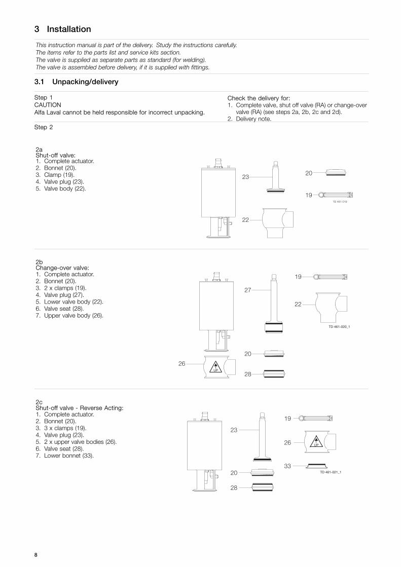
Step 1CAUTIONAlfa Laval cannot be held responsible for incorrect unpacking.
Check the delivery for:1. Complete valve, shut off valve (RA) or change-over
valve (RA) (see steps 2a, 2b, 2c and 2d).2. Delivery note.
Step 2
2aShut-off valve:1. Complete actuator.2. Bonnet (20).3. Clamp (19).4. Valve plug (23).5. Valve body (22).
2bChange-over valve:1. Complete actuator.2. Bonnet (20).3. 2 x clamps (19).4. Valve plug (27).5. Lower valve body (22).6. Valve seat (28).7. Upper valve body (26).
UP
TD 461-020_1
2cShut-off valve - Reverse Acting:1. Complete actuator.2. Bonnet (20).3. 3 x clamps (19).4. Valve plug (23).5. 2 x upper valve bodies (26).6. Valve seat (28).7. Lower bonnet (33).
UP
TD 461-021_1
8

3 Installation
This instruction manual is part of the delivery. Study the instructions carefully.The items refer to the parts list and service kits section.The valve is supplied as separate parts as standard (for welding).The valve is assembled before delivery, if it is supplied with fittings.
2dChange-over valve - Reverse Acting:1. Complete actuator.2. Bonnet (20).3. 4 x clamps (19).4. Upper valve plug (34).5. Lower valve plug (35).6. 3 x upper valve bodies (26).7. 2 x valve seats (28).8. Lower bonnet (33).
UP
TD 461-022_1
Step 3Remove possible packing materials from the valve/valve parts.Inspect the valve/valve parts for visible transport damage.Avoid damaging the valve/valve parts.
9
3 Installation
Study the instructions carefully and pay special attention to the warnings!The valve has welding ends as standard but can also be supplied with fittings.
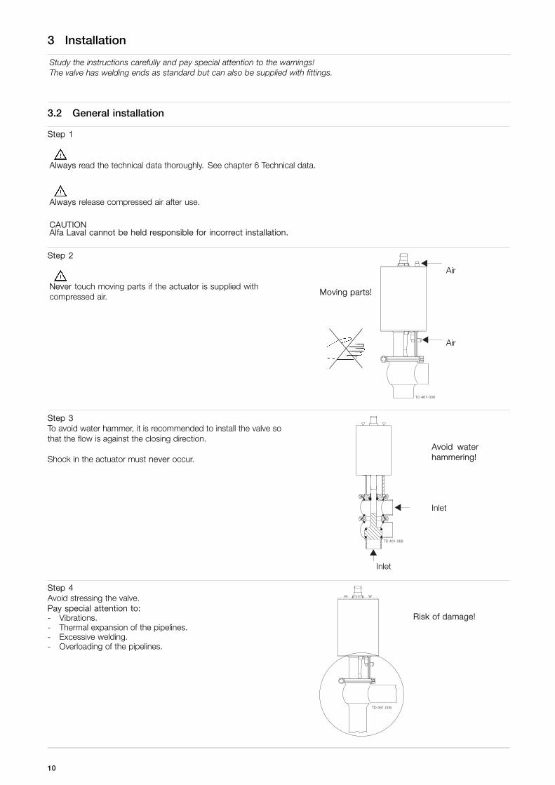
3.2 General installation
Step 1
Always read the technical data thoroughly. See chapter 6 Technical data.
Always release compressed air after use.
CAUTIONAlfa Laval cannot be held responsible for incorrect installation.
Step 2
Never touch moving parts if the actuator is supplied withcompressed air.
Air
Moving parts!
Air
Step 3To avoid water hammer, it is recommended to install the valve sothat the flow is against the closing direction.
Shock in the actuator must never occur.Avoid waterhammering!
Inlet
Inlet
Step 4Avoid stressing the valve.Pay special attention to:- Vibrations.- Thermal expansion of the pipelines.- Excessive welding.- Overloading of the pipelines.
Risk of damage!
10

3 Installation
Study the instructions carefully.The valve is supplied as separate parts to facilitate welding.The items refer to the parts list and service kits section.Check the valve for smooth operation after welding.
3.3 Welding
Step 1Always install valves with more than one valve body so that theseals between the valve bodies can be replaced. Do not weldmore than one valve body into the system.
Valve size A (mm) B (mm)
DN25/25 mm * 630
DN40/38 mm * 700
DN50/51 mm * 750
DN65/63.5 mm * 740
DN80/76 mm * 800
DN100/101.6 mm * 790
* Depending on body combination and piping solution.
B (incl. top unit)
A*
Step 2Assemble the valve in accordance with the steps on page 19.Pay special attention to the warnings!
Step 3Pre-use check:1. Supply compressed air to the actuator.2. Open and close the valve several times to ensure that it
operates smoothly.Pay special attention to the warnings!
Air
AirOpen/close!
11
3 Installation
Study the instructions carefully.The valve is supplied as separate parts to facilitate welding.The items refer to the parts list and service kits section.Check the valve for smooth operation after welding.
3.4 Recycling information
• Unpacking
- Packing material consists of wood, plastics, cardboard boxes and in some cases metal straps- Wood and cardboard boxes can be re-used, recycled or used for energy recovery- Plastics should be recycled or burnt at a licensed waste incineration plant- Metal straps should be sent for material recycling
• Maintenance
- During maintenance, oil and wearing parts in the machine are replaced- All metal parts should be sent for material recycling- Worn out or defective electronic parts should be sent to a licensed handler for material recycling- Oil and all non-metal wear parts must be disposed off in agreement with local regulations
• Scrapping
- At end of use, the equipment must be recycled according to the relevant, local regulations. Besides the equipment itself,any hazardous residues from the process liquid must be considered and dealt with in a proper manner. When in doubt, orin the absence of local regulations, please contact your local Alfa Laval sales company
12

4 Operation
Study the instructions carefully and pay special attention to the warnings!Ensure that the valve operates smoothly.The items refer to the parts list and service kits section.
4.1 Operation
Step 1
Always read the technical data thoroughly. See chapter 6 Technical data.
Always release compressed air after use.
CAUTIONAlfa Laval cannot be held responsible for incorrect operation.
Step 2
Never touch the valve or the pipelines when processing hotliquids or when sterilising. Danger of burns!
Step 3
Never touch moving parts if the actuator is supplied withcompressed air.
Air
Moving parts!
Air
Step 4Lubrication of valves:1. Ensure smooth movement between lip seal (25) and
plug stem (23, 27).2. Lubricate with Klüber Paraliq GTE 703 if necessary
(see page 16).
Shut-off valve Change-over valve
13
4 Operation
Pay attention to possible faults. Study the instructions carefully.The items refer to the parts list and service kits section.
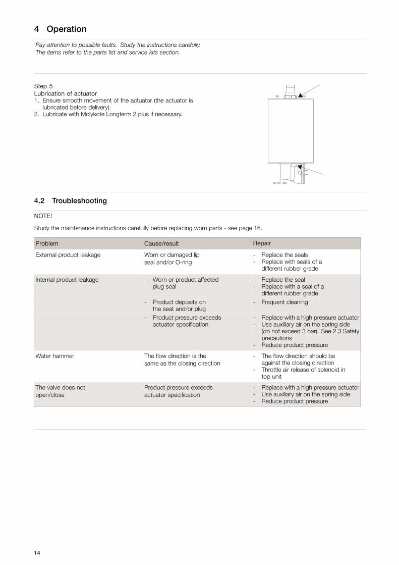
Step 5Lubrication of actuator1. Ensure smooth movement of the actuator (the actuator is
lubricated before delivery).2. Lubricate with Molykote Longterm 2 plus if necessary.
4.2 Troubleshooting
NOTE!
Study the maintenance instructions carefully before replacing worn parts - see page 16.
Problem Cause/result Repair
External product leakage Worn or damaged lipseal and/or O-ring
- Replace the seals- Replace with seals of a
different rubber grade
Internal product leakage - Worn or product affectedplug seal
- Replace the seal- Replace with a seal of a
different rubber grade- Product deposits on
the seat and/or plug- Frequent cleaning
- Product pressure exceedsactuator specification
- Replace with a high pressure actuator- Use auxiliary air on the spring side
(do not exceed 3 bar). See 2.3 Safetyprecautions
- Reduce product pressure
Water hammer The flow direction is thesame as the closing direction
- The flow direction should beagainst the closing direction
- Throttle air release of solenoid intop unit
The valve does notopen/close
Product pressure exceedsactuator specification
- Replace with a high pressure actuator- Use auxiliary air on the spring side- Reduce product pressure
14

4 Operation
The valve is designed for cleaning in place (CIP).Study the instructions carefully and pay special attention to the warnings!NaOH = Caustic Soda.HNO3 = Nitric acid.
4.3 Recommended cleaning
Step 1
Always handle lye and acid with great care.
Caustic danger!
Always userubber gloves!
Always useprotective goggles!
Step 2
Never touch the valve or the pipelines when sterilising.Danger of burns!
Step 3Clean the plug and the seats correctly.Pay special attention to the warningsLift and lower valve plug momentarily!
Shut-off valve Change-over valve
Step 4Examples of cleaning agents:Use clean water, free from chlorides.
1. 1% by weight NaOH at 70o C 2. 0.5% by weight HNO3 at 70o C
1 kgNaOH
+ 100 lwater
= Cleaning agent. 0.7 l53% HNO3
+ 100 lwater
= Cleaning agent.
2.2 l33% NaOH
+ 100 lwater
= Cleaning agent.
Step 51. Avoid excessive concentration of the cleaning agent.2. Adjust the cleaning flow to the process.3. Always rinse well with clean water after the cleaning.NOTEThe cleaning agents must be stored/disposed of in accordancewith current regulations/directives.
Always rinse!
Clean water Cleaning agents
15

5 Maintenance
Maintain the valve regularly.Study the instructions carefully and pay special attention to the warnings!Always keep spare rubber seals and lip seals in stock.Check the valve for smooth operation after service.
5.1 General maintenance
Step 1
Always read the technical data thoroughly. See chapter 6 Technical data.
Always release compressed air after use.
NOTEAll scrap must be stored/discharged in accordance with current regulations/directives.
Step 2
Never service the valve when it is hot.
Never service the valve with valve and pipelines under pressure.
Atmosphericpressurerequired!
Danger of burns!
Step 3
Never stick your fingers through the valve ports if the actuator issupplied with compressed air.
Air
Danger of cuts!
Air
Step 4
Never touch the moving parts if the actuator is supplied withcompressed air.
Air
Moving parts!
Air
16
5 Maintenance
Maintain the valve regularly.Study the instructions carefully and pay special attention to the warnings!Always keep spare rubber seals and lip seals in stock.Check the valve for smooth operation after service.
Below are some guidelines for maintenance and lubrication intervals. Please note that the guidelines are for normalworking conditions in one shift.
Product wetted seals Actuator bushings complete
Preventivemaintenance
Replace after12 months dependingon working conditions
Replace after5 years dependingon working conditions
Maintenance afterleakage (leakagenormally starts slowly)
Replace at theend of the day
Replace whenpossible
Plannedmaintenance
- Regular inspectionfor leakage andsmooth operation
- Keep a record ofthe valve
- Use the statistics forinspection planningReplace after leakage
- Regular inspectionfor leakage andsmooth operation
- Keep a record ofthe actuator
- Use the statistics forinspection planningReplace after leakage
Lubrication
Before fittingKlüber Paraliq GTE 703or similar USDA H1approved oil/grease
Before fittingMolykote Longterm 2 plus
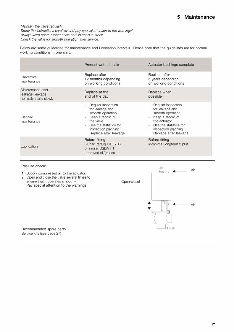
Pre-use check:Air
Open/close!
1. Supply compressed air to the actuator.2. Open and close the valve several times to
ensure that it operates smoothly.Pay special attention to the warnings!
Air
Recommended spare partsService kits (see page 27)
17
5 Maintenance
Study the instructions carefully. The items refer to the parts list and service kits section. Handle scrap correctly.NC = Normally closed.NO = Normally open.A/A = Air/air activated.
5.2 Dismantling the valve
Step 1
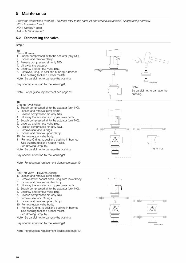
1aShut-off valve:1. Supply compressed air to the actuator (only NC).2. Loosen and remove clamp.3. Release compressed air (only NC).4. Lift away the actuator.5. Unscrew and remove valve plug.6. Remove O-ring, lip seal and bushing in bonnet.
(Use bushing tool and rubber mallet).Note! Be careful not to damage the bushing.
Pay special attention to the warnings!TD 461-959
Note!Be careful not to damage thebushing.
Note! For plug seal replacement see page 19.
1bChange-over valve:1. Supply compressed air to the actuator (only NC).2. Loosen and remove lower clamp.3. Release compressed air (only NC).4. Lift away the actuator and upper valve body.5. Supply compressed air to the actuator (only NO).6. Unscrew and remove valve plug.7. Release compressed air (only NO).8. Remove seat and O-rings.9. Loosen and remove upper clamp.10. Remove upper valve body.11. Remove O-ring, lip seal and bushing in bonnet.
(Use bushing tool and rubber mallet.See drawing, step 1a).
Note! Be careful not to damage the bushing.
Pay special attention to the warnings!
Note! For plug seal replacement please see page 19.
UP
TD 461-044_2
1cShut-off valve - Reverse Acting:1. Loosen and remove lower clamp.2. Remove lower bonnet and O-ring from lower body.3. Loosen and remove middle clamp.4. Lift away the actuator and upper valve body.5. Supply compressed air to the actuator (only NC).6. Unscrew and remove valve plug.7. Release compressed air (only NC).8. Remove seat and O-rings.9. Loosen and remove upper clamp.10. Remove upper valve body.11. Remove O-ring, lip seal and bushing in bonnet.
(Use bushing tool and rubber mallet.See drawing, step 1a).
Note! Be careful not to damage the bushing.
Pay special attention to the warnings!
Note! For plug seal replacement please see page 19.
UP
TD 462-004_2
UP
18
5 Maintenance
Study the instructions carefully. The items refer to the parts list and service kits section. Handle scrap correctly.NC = Normally closed.NO = Normally open.A/A = Air/air activated.
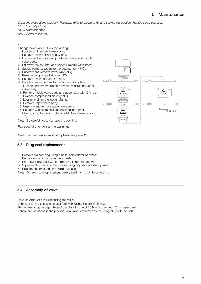
1dChange-over valve - Reverse Acting:1. Loosen and remove lower clamp.2. Remove lower bonnet and O-ring.3. Loosen and remove clamp between lower and middle
valve body.4. Lift away the actuator and upper + middle valve body.5. Supply compressed air to the actuator (only NC).6. Unscrew and remove lower valve plug.7. Release compressed air (only NC).8. Remove lower seat and O-rings.9. Supply compressed air to the actuator (only NO).10. Loosen and remove clamp between middle and upper
valve body.11. Remove middle valve body and upper seat with O-rings.12. Release compressed air (only NO).13. Loosen and remove upper clamp.14. Remove upper valve body.15. Unscrew and remove upper valve plug.16. Remove O-ring, lip seal and bushing in bonnet.
(Use bushing tool and rubber mallet. See drawing, step1a).
Note! Be careful not to damage the bushing.
Pay special attention to the warnings!
Note! For plug seal replacement please see page 19.
UP
UP
TD 462-003_2
UP
5.3 Plug seal replacement
1. Remove old seal ring using a knife, screwdriver or similar.Be careful not to damage metal parts.
2. Pre-mount plug seal without pressing it into the groove.3. Squeeze plug seal into the groove using opposite pressure points.4. Release compressed air behind plug seal.Note! For plug seal replacement please read instruction in service kit.
5.4 Assembly of valve
Reverse order of 5.2 Dismantling the valve.Lubricate O-ring (21) and lip seal (25) with Klüber Paraliq GTE 703.Remember to tighten spindle and plug to a torque of 30 Nm (to use two 17 mm spanners)If there are vibrations in the pipeline, Alfa Laval recommends the using of Loctite no. 243.
19

5 Maintenance
Study the instructions carefully.The items refer to the parts list and service kits section. Handle scrap correctly.A/A = Air/air activated.Service tool: See spare parts.
5.5 Actuator bushing replacement
Step 1Introduction- The actuator service kit contains two bushings and four o-rings.- Mount the thick o-ring inside and the thin o-ring outside the
bushing.- Always lubricate the spindle and o-rings thoroughly with
“Molykote LongTerm 2 Plus” before mounting the newbushings.
2200-0000
Step 2Introduction - Standard socket wrenchUse a 27 mm socket wrench to mount the bushings, as the space in the yoke is limited.A socket wrench 24x27 (length = 185 mm) is a standard tool, which can be purchased from all tool shops.
A = 185 mm
2200-0001
A
Example:Socket wrench - 24x27 mmSupplier: Gedore ToolEAN4010886621264
2200-0002
20
5 Maintenance
Study the instructions carefully.The items refer to the parts list and service kits section. Handle scrap correctly.A/A = Air/air activated.Service tool: See spare parts.
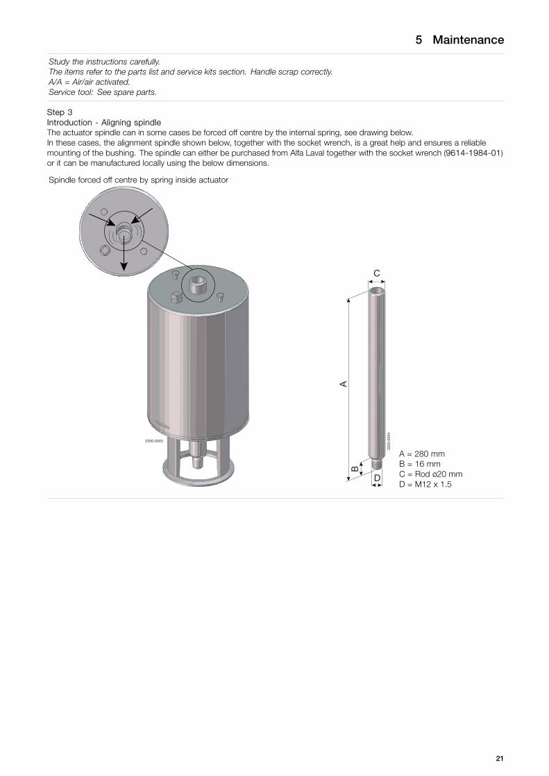
Step 3Introduction - Aligning spindleThe actuator spindle can in some cases be forced off centre by the internal spring, see drawing below.In these cases, the alignment spindle shown below, together with the socket wrench, is a great help and ensures a reliablemounting of the bushing. The spindle can either be purchased from Alfa Laval together with the socket wrench (9614-1984-01)or it can be manufactured locally using the below dimensions.
Spindle forced off centre by spring inside actuator
2200-0003
2200
-000
4
AB
D
C
A = 280 mmB = 16 mmC = Rod ø20 mmD = M12 x 1.5
21
5 Maintenance
Study the instructions carefully.The items refer to the parts list and service kits section. Handle scrap correctly.A/A = Air/air activated.Service tool: See spare parts.
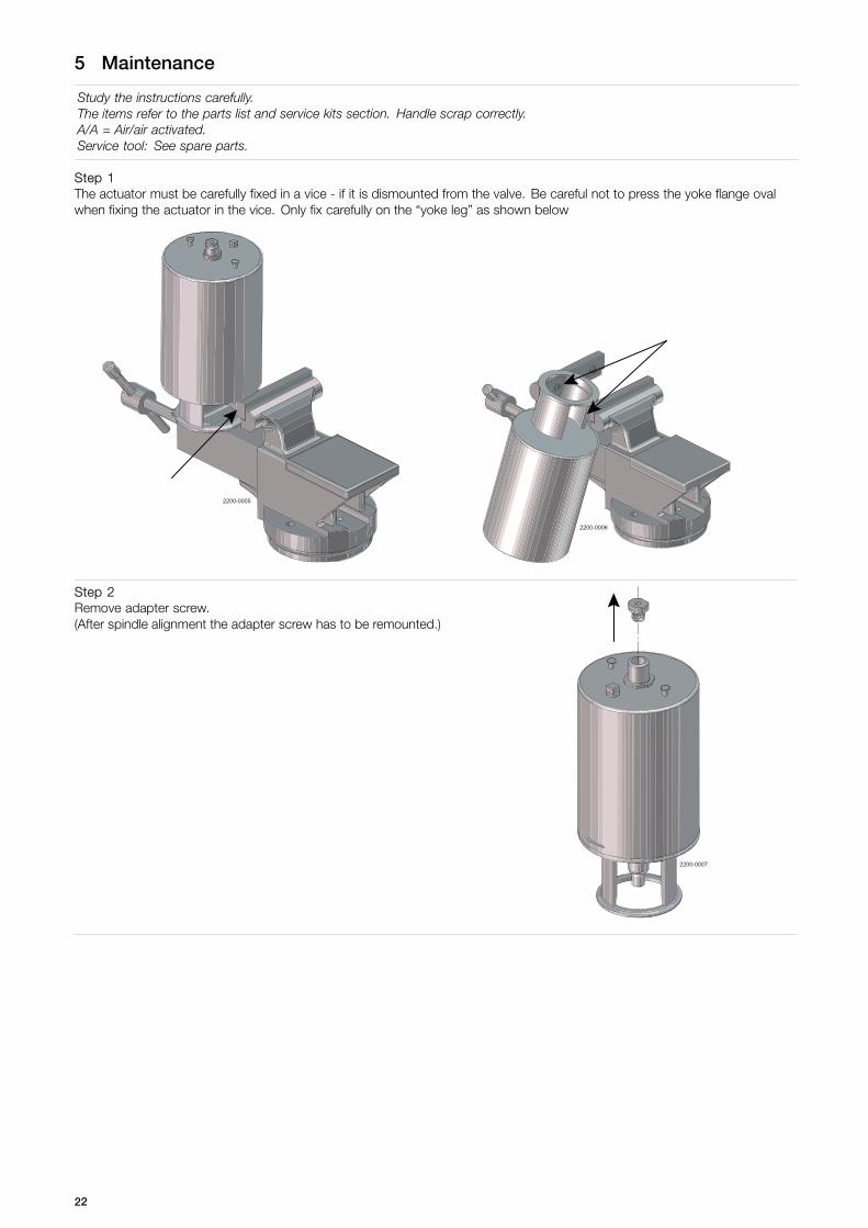
Step 1The actuator must be carefully fixed in a vice - if it is dismounted from the valve. Be careful not to press the yoke flange ovalwhen fixing the actuator in the vice. Only fix carefully on the “yoke leg” as shown below
2200-0005
2200-0006
Step 2Remove adapter screw.(After spindle alignment the adapter screw has to be remounted.)
2200-0007
22

5 Maintenance
Study the instructions carefully.The items refer to the parts list and service kits section. Handle scrap correctly.A/A = Air/air activated.Service tool: See spare parts.
Step 31. Lubricate thoroughly both the actuator spindle and o-rings.2. Grease with “Molykote LongTerm 2 plus”.3. Fit the bushing on the spindle.
2200-0008
Step 4Fit the aligning spindle to the actuator spindle, and then mount the socket wrench.
2200-0009 2200-0010
Aligning spindle Socket wrench
23

5 Maintenance
Study the instructions carefully.The items refer to the parts list and service kits section. Handle scrap correctly.A/A = Air/air activated.Service tool: See spare parts.
Step 5Now pull the aligning spindle to centre the actuator spindle. In this position rotate the bushing 180° backwards and then beginto fasten the bushing. Make sure that the thread catches evenly!The bushing must only be tightened with a torque of 10 Nm (7 lbf -ft) - which can be done by turning “hard” by hand.
2200-0011
24
5 Maintenance
Study the instructions carefully.The items refer to the parts list and service kits section. Handle scrap correctly.A/A = Air/air activated.Service tool: See spare parts.
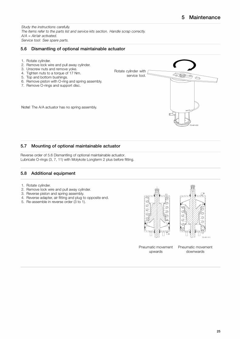
5.6 Dismantling of optional maintainable actuator
1. Rotate cylinder.2. Remove lock wire and pull away cylinder.3. Unscrew nuts and remove yoke.4. Tighten nuts to a torque of 17 Nm.5. Top and bottom bushings.6. Remove piston with O-ring and spring assembly.7. Remove O-rings and support disc.
Rotate cylinder withservice tool.
Note! The A/A actuator has no spring assembly.
TD 461-033
5.7 Mounting of optional maintainable actuator
Reverse order of 5.6 Dismantling of optional maintainable actuator.Lubricate O-rings (3, 7, 11) with Molykote Longterm 2 plus before fitting.
5.8 Additional equipment
1. Rotate cylinder.2. Remove lock wire and pull away cylinder.3. Reverse piston and spring assembly.4. Reverse adapter, air fitting and plug to opposite end.5. Re-assemble in reverse order (3 to 1).
Pneumatic movementupwards
Pneumatic movementdownwards
25
6 Technical data
It is important to observe the technical data during installation, operation and maintenance.Inform all personnel about the technical data.
6.1 Technical data
Data - valve/actuator
Max. product pressure 1000 kPa (10 bar).
Min. product pressure Full vacuum (depending on product specifications).
Temperature range -10o C to + 140o C (standard EPDM seal).
Air pressure, actuator 500 to 700 kPa (5 to 7 bar).
Materials - valve/actuator
Product wetted steel parts 1.4404 (316L) (internal Ra < 0.8 µm).
Other steel parts 1.4301 (304).
Plug seal EPDM / PTFE (TR2).
Other product wetted seals EPDM (standard).
Optional product wetted seals HNBR and FPM.
Other seals NBR.
NoiseOne metre away from and 1.6 metres above the exhaust the noise level of a valve actuator will be approximately 77db (A)without noise damper and approximately 72 db (A) with damper - measured at 7 bar air-pressure.
26

7 Parts list and service kits
The drawing shows Unique Single Seat Valve.The items refer to the parts list in the following sections.
7.1 Drawing
Shut-off valve Change-over valve
27

7 Parts list and service kits
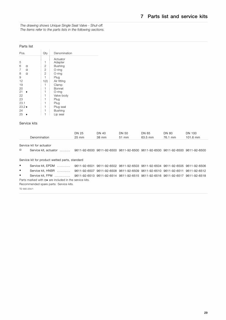
The drawing shows Unique Single Seat Valve - Shut-off.The items refer to the parts lists in the following sections.
7.2 Unique Single Seat Valve - Shut-off Valve
TD 461-075_1
28
7 Parts list and service kits
The drawing shows Unique Single Seat Valve - Shut-off.The items refer to the parts lists in the following sections.
Parts list
Pos. Qty Denomination
Actuator5 1 Adapter6 2 Bushing7 2 O-ring8 2 O-ring9 1 Plug12 1(2) Air fitting19 1 Clamp20 1 Bonnet21 ♦ 1 O-ring22 1 Valve body23 1 Plug23.1 1 Plug23.2 ♦ 1 Plug seal24 1 Bushing25 ♦ 1 Lip seal
Service kits
DenominationDN 2525 mm
DN 4038 mm
DN 5051 mm
DN 6563.5 mm
DN 8076.1 mm
DN 100101.6 mm
Service kit for actuator Service kit, actuator . . . . . . . . 9611-92-6500 9611-92-6500 9611-92-6500 9611-92-6500 9611-92-6500 9611-92-6500
Service kit for product wetted parts, standard
♦ Service kit, EPDM . . . . . . . . . . 9611-92-6501 9611-92-6502 9611-92-6503 9611-92-6504 9611-92-6505 9611-92-6506♦ Service kit, HNBR . . . . . . . . . . 9611-92-6507 9611-92-6508 9611-92-6509 9611-92-6510 9611-92-6511 9611-92-6512♦ Service kit, FPM . . . . . . . . . . . . 9611-92-6513 9611-92-6514 9611-92-6515 9611-92-6516 9611-92-6517 9611-92-6518Parts marked with ♦ are included in the service kits.Recommended spare parts: Service kits.
TD 900-254/1
29

7 Parts list and service kits
The drawing shows Unique Single Seat Valve - Change-over.The items refer to the parts lists in the following sections.
7.3 Unique Single Seat Valve - Change-over Valve
TD 461-969
25 mm/DN25
38-51 mm/DN40-50
63.5-101.6 mm/DN65-100
30

7 Parts list and service kits
The drawing shows Unique Single Seat Valve - Change-over.The items refer to the parts lists in the following sections.
Parts list
Pos. Qty Denomination
Actuator5 1 Adapter6 2 Bushing7 2 O-ring8 2 O-ring9 1 Plug12 1(2) Air fitting19 2 Clamp20 1 Bonnet21 ♦ 3 O-ring22 1 Valve body24 1 Bushing25 ♦ 1 Lip seal26 1 Valve body27 1 Plug27.1 1 Plug27.2 ♦ 2 Plug seal28 1 Seat
Service kits
Service kit for actuator Service kit, actuator . . . . . . . . 9611-92-6500 9611-92-6500 9611-92-6500 9611-92-6500 9611-92-6500 9611-92-6500
Service kit for product wetted parts, standard
♦ Service kit, EPDM . . . . . . . . . . 9611-92-6579 9611-92-6580 9611-92-6581 9611-92-6582 9611-92-6583 9611-92-6584♦ Service kit, HNBR . . . . . . . . . . 9611-92-6585 9611-92-6586 9611-92-6587 9611-92-6588 9611-92-6589 9611-92-6590♦ Service kit, FPM . . . . . . . . . . . . 9611-92-6591 9611-92-6592 9611-92-6593 9611-92-6594 9611-92-6595 9611-92-6596Parts marked with ♦ are included in the service kits.Recommended spare parts: Service kits.
TD 900-254/1
31

.
32

7 Parts list and service kits
The drawing shows Unique Single Seat Valve - Change-over.The items refer to the parts lists in the following sections.
7.4 Drawing
Shut-off valve - Reverse Acting Change-over valve - Reverse Acting
33
7 Parts list and service kits
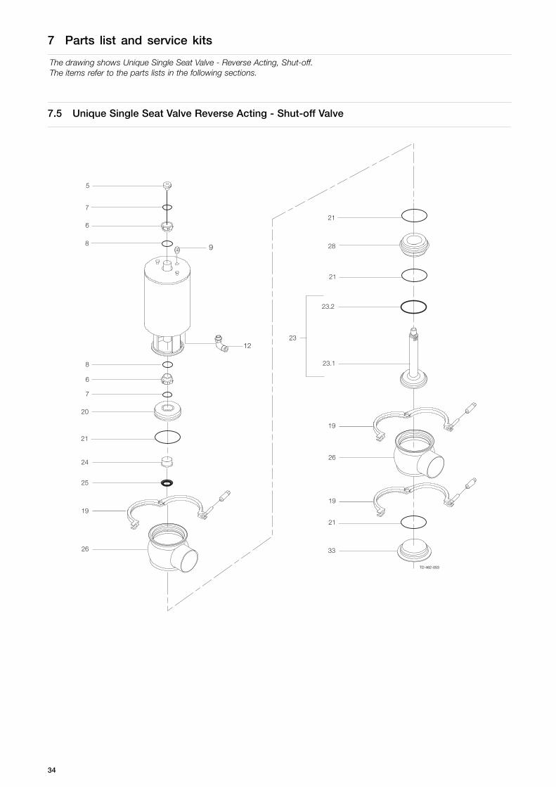
The drawing shows Unique Single Seat Valve - Reverse Acting, Shut-off.The items refer to the parts lists in the following sections.
7.5 Unique Single Seat Valve Reverse Acting - Shut-off Valve
34

7 Parts list and service kits
The drawing shows Unique Single Seat Valve - Reverse Acting, Shut-off.The items refer to the parts lists in the following sections.
Parts list
Pos. Qty Denomination
Actuator5 1 Adapter6 2 Bushing7 2 O-ring8 2 O-ring9 1 Plug12 1(2) Air fitting19 3 Clamp20 1 Bonnet21 ♦ 4 O-ring23 1 Plug23.1 1 Plug23.2 ♦ 1 Plug seal24 1 Bushing25 ♦ 1 Lip seal26 2 Valve body28 1 Seat33 1 Lower bonnet
Service kits
DenominationDN 2525 mm
DN 4038 mm
DN 5051 mm
DN 6563.5 mm
DN 8076.1 mm
DN 100101.6 mm
Service kit for actuator Service kit . . . . . . . . . . . . . . . . . . 9611-92-6500 9611-92-6500 9611-92-6500 9611-92-6500 9611-92-6500 9611-92-6500
Service kit for product wetted parts, standard
♦ Service kit, EPDM . . . . . . . . . . 9611-92-6525 9611-92-6526 9611-92-6527 9611-92-6528 9611-92-6529 9611-92-6530♦ Service kit, HNBR . . . . . . . . . . 9611-92-6531 9611-92-6532 9611-92-6533 9611-92-6534 9611-92-6535 9611-92-6536♦ Service kit, FPM . . . . . . . . . . . . 9611-92-6537 9611-92-6538 9611-92-6539 9611-92-6540 9611-92-6541 9611-92-6542Parts marked with ♦ are included in the service kits.Recommended spare parts: Service kits.
TD 900-350/1
35

7 Parts list and service kits
The drawing shows Unique Single Seat Valve - Reverse Acting, Change-over.The items refer to the parts lists in the following sections.
7.6 Unique Single Seat Valve Reverse Acting - Change-over Valve
TD 462-054
36

7 Parts list and service kits
The drawing shows Unique Single Seat Valve - Reverse Acting, Change-over.The items refer to the parts lists in the following sections.
Parts list
Pos. Qty Denomination
Actuator5 1 Adapter6 2 Bushing7 2 O-ring8 2 O-ring9 1 Plug12 1(2) Air fitting19 4 Clamp20 1 Bonnet21 ♦ 6 O-ring24 1 Bushing25 ♦ 1 Lip seal26 3 Valve body28 2 Seat33 1 Lower bonnet34 1 Plug34.1 1 Plug34.2 ♦ 1 Plug seal34.3 ♦ 1 O-ring35 1 Plug35.1 1 Plug35.2 ♦ 1 Plug seal
Service kits
DenominationDN 2525 mm
DN 4038 mm
DN 5051 mm
DN 6563.5 mm
DN 8076.1 mm
DN 100101.6 mm
Service kit for actuator Service kit . . . . . . . . . . . . . . . . . . 9611-92-6500 9611-92-6500 9611-92-6500 9611-92-6500 9611-92-6500 9611-92-6500
Service kit for product wetted parts, standard
♦ Service kit, EPDM . . . . . . . . . . 9611-92-6597 9611-92-6598 9611-92-6599 9611-92-6600 9611-92-6601 9611-92-6602♦ Service kit, HNBR . . . . . . . . . . 9611-92-6603 9611-92-6604 9611-92-6605 9611-92-6606 9611-92-6607 9611-92-6608♦ Service kit, FPM . . . . . . . . . . . . 9611-92-6609 9611-92-6610 9611-92-6611 9611-92-6612 9611-92-6613 9611-92-6614
Parts marked with ♦ are included in the service kits.
Recommended spare parts: Service kits.
TD 900-350/1
37
7 Parts list and service kits
The drawing shows Unique Single Seat Valve - Reverse Acting, Change-over.The items refer to the parts lists in the following sections.
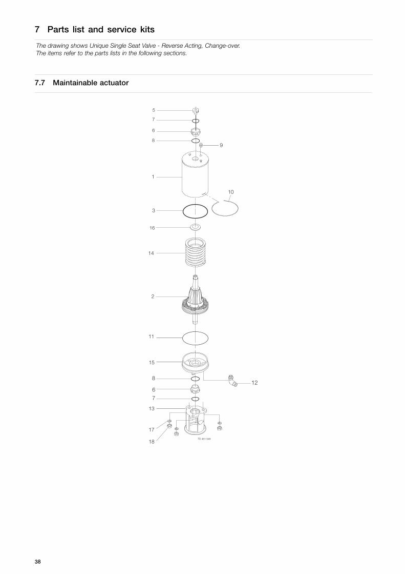
7.7 Maintainable actuator
38
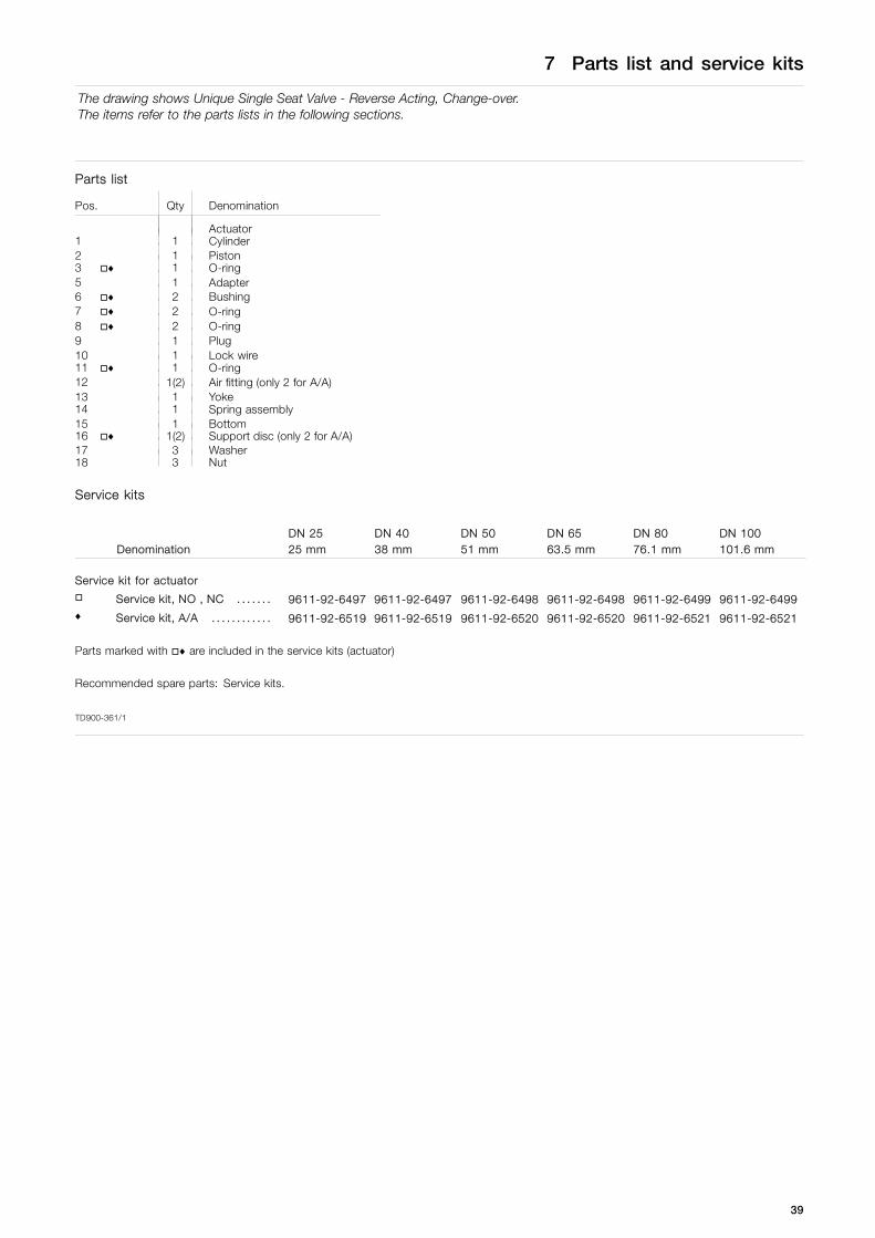
7 Parts list and service kits
The drawing shows Unique Single Seat Valve - Reverse Acting, Change-over.The items refer to the parts lists in the following sections.
Parts list
Pos. Qty Denomination
Actuator1 1 Cylinder2 1 Piston3 ♦ 1 O-ring5 1 Adapter6 ♦ 2 Bushing7 ♦ 2 O-ring8 ♦ 2 O-ring9 1 Plug10 1 Lock wire11 ♦ 1 O-ring12 1(2) Air fitting (only 2 for A/A)13 1 Yoke14 1 Spring assembly15 1 Bottom16 ♦ 1(2) Support disc (only 2 for A/A)17 3 Washer18 3 Nut
Service kits
DenominationDN 2525 mm
DN 4038 mm
DN 5051 mm
DN 6563.5 mm
DN 8076.1 mm
DN 100101.6 mm
Service kit for actuator Service kit, NO , NC . . . . . . . 9611-92-6497 9611-92-6497 9611-92-6498 9611-92-6498 9611-92-6499 9611-92-6499♦ Service kit, A/A . . . . . . . . . . . . 9611-92-6519 9611-92-6519 9611-92-6520 9611-92-6520 9611-92-6521 9611-92-6521
Parts marked with ♦ are included in the service kits (actuator)
Recommended spare parts: Service kits.
TD900-361/1
39

How to contact Alfa LavalContact details for all countries arecontinually updated on our website.Please visit www.alfalaval.com to access the information directly.
© Alfa Laval Corporate ABThis document and its contents is owned by Alfa Laval Corporate AB and protected by laws governing intellectual property and thereto related rights. It is the responsibility of the user of thisdocument to comply with all applicable intellectual property laws. Without limiting any rights related to this document, no part of this document may be copied, reproduced or transmitted in anyform or by any means (electronic, mechanical, photocopying, recording, or otherwise), or for any purpose, without the expressed permission of Alfa Laval Corporate AB. Alfa Laval Corporate ABwill enforce its rights related to this document to the fullest extent of the law, including the seeking of criminal prosecution.