Embed Size (px)
Citation preview
Designation: A1023/A1023M – 09
Standard Specification forStranded Carbon Steel Wire Ropes for General Purposes1
This standard is issued under the fixed designation A1023/A1023M; the number immediately following the designation indicates theyear of original adoption or, in the case of revision, the year of last revision. A number in parentheses indicates the year of lastreapproval. A superscript epsilon (´) indicates an editorial change since the last revision or reapproval.
1. Scope*
1.1 This specification covers the general requirements forthe more common types of stranded steel wire ropes. Includedin this specification are wire ropes in various grades andconstructions from 1⁄4 in. [6 mm] to 23⁄8 in. [60 mm] manufac-tured from uncoated or metallic coated wire. Also included arecord products from 1⁄32 in. [0.8 mm] to 3⁄8 in. [10 mm]manufactured from metallic coated wire. For specific applica-tions, additional or alternative requirements may apply.
1.2 The values stated in either inch-pounds or SI units are tobe regarded separately as standard. Within the text, the SI unitsare shown in brackets. The values stated in each system are notexact equivalents; therefore, each system shall be used inde-pendently of the other. Combining values from the two systemsmay result in nonconformance with the specification.
2. Referenced Documents
2.1 ASTM Standards:2
A931 Test Method for Tension Testing of Wire Ropes andStrand
A1007 Specification for Carbon Steel Wire for Wire Rope2.2 ISO Standards:3
ISO 2232 Round Drawn Wire for General-Purpose Non-alloy Steel Wire Ropes
ISO 3108 Steel Wire Ropes for General Purposes—Determination of Actual Breaking
3. Terminology
Description of Terms Specific to this Specification
3.1 inserts, n—fiber or solid polymer so positioned as toseparate adjacent strands or wires in the same or overlyinglayers or to fill interstices of the rope.
3.2 Lubrication:3.2.1 impregnating compound, n—material used in the
manufacture of natural fiber cores, covers, or inserts for thepurpose of providing protection against rotting and decay ofthe fiber material.
3.2.2 preservation compound, n—material, usually contain-ing some form of blocking agent, applied during, after, or bothduring and after manufacture of the rope to fiber inserts, fillers,and coverings for the purpose of providing protection againstcorrosion.
3.2.3 rope lubricant, n—general term used to signify mate-rial applied during the manufacture of a strand, core, or ropefor the purpose of reducing internal friction, providing protec-tion against corrosion, or both.
3.3 rope cores, n—central element, usually of fiber or steel(but may be a combination of both), of a round rope aroundwhich are laid helically the strands of a stranded rope or theunit ropes of a cable-laid rope (Fig. 1).
3.3.1 fiber core (FC), n—an element made from eithernatural or synthetic fibers.
3.3.2 solid polymer core, n—a single element of solidpolymer material that is either cylindrical or shaped (grooved).It may also include an element or elements of wire or fiber.
3.3.3 steel core, n—a stranded rope (IWRC), or a roundstrand (WSC) construction. The round strand or the strandedrope core or its outer strands, or both, may also be covered orfilled with either fiber or solid polymer. Steel cores arenormally made as a separate independent element, the excep-tion being rope with a stranded rope core closed parallel withthe outer strands.
3.4 strand, n—an element of rope normally consisting of anassembly of wires of appropriate shape and dimensions laidhelically in one or more layers around a center. The center mayconsist of one round or shaped wire, of several round wiresforming a built-up center, or of fiber or some other material. Ifmultiple wires are used in a strand center, they may be countedas one wire.
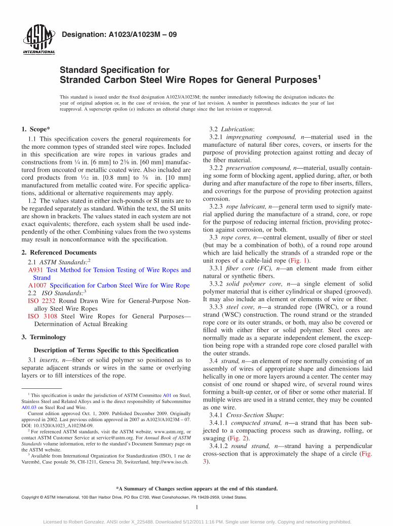
3.4.1 Cross-Section Shape:3.4.1.1 compacted strand, n—a strand that has been sub-
jected to a compacting process such as drawing, rolling, orswaging (Fig. 2).
3.4.1.2 round strand, n—strand having a perpendicularcross-section that is approximately the shape of a circle (Fig.3).
1 This specification is under the jurisdiction of ASTM Committee A01 on Steel,Stainless Steel and Related Alloys and is the direct responsibility of SubcommitteeA01.03 on Steel Rod and Wire.
Current edition approved Oct. 1, 2009. Published December 2009. Originallyapproved in 2002. Last previous edition approved in 2007 as A1023/A1023M – 07.DOI: 10.1520/A1023_A1023M-09.
2 For referenced ASTM standards, visit the ASTM website, www.astm.org, orcontact ASTM Customer Service at [email protected]. For Annual Book of ASTMStandards volume information, refer to the standard’s Document Summary page onthe ASTM website.
3 Available from International Organization for Standardization (ISO), 1 rue deVarembé, Case postale 56, CH-1211, Geneva 20, Switzerland, http://www.iso.ch.
1
*A Summary of Changes section appears at the end of this standard.
Copyright © ASTM International, 100 Barr Harbor Drive, PO Box C700, West Conshohocken, PA 19428-2959, United States.
Licensed to Robert Gonzalez. ANSI order X_225488. Downloaded 5/12/2011 1:16 PM. Single user license only. Copying and networking prohibited.
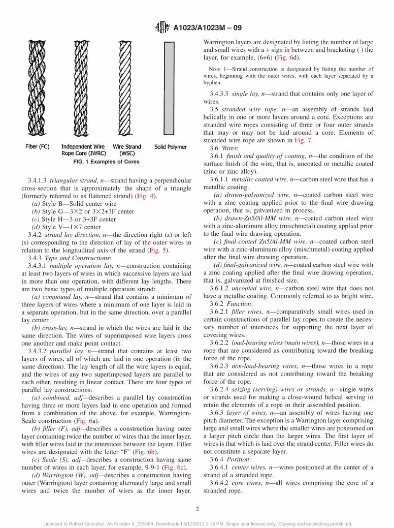
3.4.1.3 triangular strand, n—strand having a perpendicularcross-section that is approximately the shape of a triangle(formerly referred to as flattened strand) (Fig. 4).
(a) Style B—Solid center wire(b) Style G—332 or 332+3F center(c) Style H—3 or 3+3F center(d) Style V—137 center
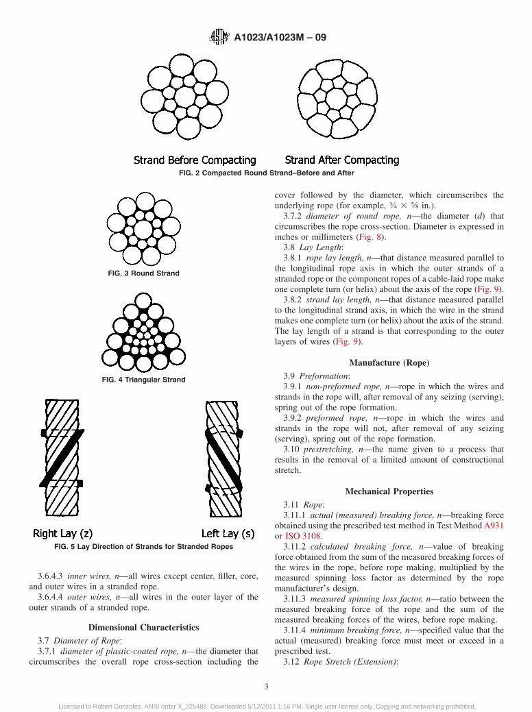
3.4.2 strand lay direction, n—the direction right (z) or left(s) corresponding to the direction of lay of the outer wires inrelation to the longitudinal axis of the strand (Fig. 5).
3.4.3 Type and Constructions:3.4.3.1 multiple operation lay, n—construction containing
at least two layers of wires in which successive layers are laidin more than one operation, with different lay lengths. Thereare two basic types of multiple operation strand:
(a) compound lay, n—strand that contains a minimum ofthree layers of wires where a minimum of one layer is laid ina separate operation, but in the same direction, over a parallellay center.
(b) cross-lay, n—strand in which the wires are laid in thesame direction. The wires of superimposed wire layers crossone another and make point contact.
3.4.3.2 parallel lay, n—strand that contains at least twolayers of wires, all of which are laid in one operation (in thesame direction). The lay length of all the wire layers is equal,and the wires of any two superimposed layers are parallel toeach other, resulting in linear contact. There are four types ofparallel lay constructions:
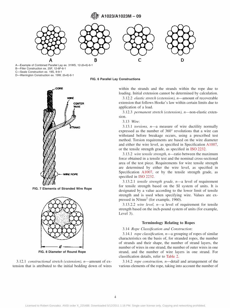
(a) combined, adj—describes a parallel lay constructionhaving three or more layers laid in one operation and formedfrom a combination of the above, for example, Warrington-Seale construction (Fig. 6a).
(b) filler (F), adj—describes a construction having outerlayer containing twice the number of wires than the inner layer,with filler wires laid in the interstices between the layers. Fillerwires are designated with the letter “F” (Fig. 6b).
(c) Seale (S), adj—describes a construction having samenumber of wires in each layer, for example, 9-9-1 (Fig. 6c).
(d) Warrington (W), adj—describes a construction havingouter (Warrington) layer containing alternately large and smallwires and twice the number of wires as the inner layer.
Warrington layers are designated by listing the number of largeand small wires with a + sign in between and bracketing ( ) thelayer, for example, (6+6) (Fig. 6d).
NOTE 1—Strand construction is designated by listing the number ofwires, beginning with the outer wires, with each layer separated by ahyphen.
3.4.3.3 single lay, n—strand that contains only one layer ofwires.
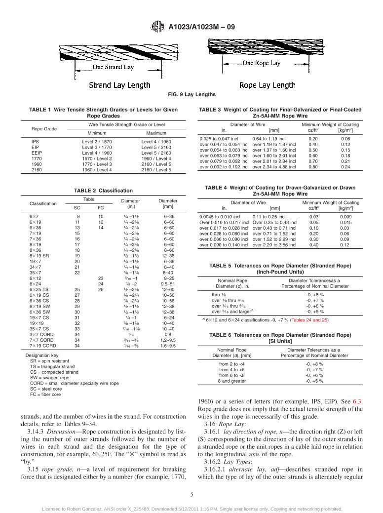
3.5 stranded wire rope, n—an assembly of strands laidhelically in one or more layers around a core. Exceptions arestranded wire ropes consisting of three or four outer strandsthat may or may not be laid around a core. Elements ofstranded wire rope are shown in Fig. 7.
3.6 Wires:3.6.1 finish and quality of coating, n—the condition of the
surface finish of the wire, that is, uncoated or metallic coated(zinc or zinc alloy).
3.6.1.1 metallic coated wire, n—carbon steel wire that has ametallic coating.
(a) drawn-galvanized wire, n—coated carbon steel wirewith a zinc coating applied prior to the final wire drawingoperation, that is, galvanized in process.
(b) drawn-Zn5/Al-MM wire, n—coated carbon steel wirewith a zinc-aluminum alloy (mischmetal) coating applied priorto the final wire drawing operation.
(c) final-coated Zn5/Al-MM wire, n—coated carbon steelwire with a zinc-aluminum alloy (mischmetal) coating appliedafter the final wire drawing operation.
(d) final-galvanized wire, n—coated carbon steel wire witha zinc coating applied after the final wire drawing operation,that is, galvanized at finished size.
3.6.1.2 uncoated wire, n—carbon steel wire that does nothave a metallic coating. Commonly referred to as bright wire.
3.6.2 Function:3.6.2.1 filler wires, n—comparatively small wires used in
certain constructions of parallel lay ropes to create the neces-sary number of interstices for supporting the next layer ofcovering wires.
3.6.2.2 load-bearing wires (main wires), n—those wires in arope that are considered as contributing toward the breakingforce of the rope.
3.6.2.3 non-load-bearing wires, n—those wires in a ropethat are considered as not contributing toward the breakingforce of the rope.
3.6.2.4 seizing (serving) wires or strands, n—single wiresor strands used for making a close-wound helical serving toretain the elements of a rope in their assembled position.
3.6.3 layer of wires, n—an assembly of wires having onepitch diameter. The exception is a Warrington layer comprisinglarge and small wires where the smaller wires are positioned ona larger pitch circle than the larger wires. The first layer ofwires is that which is laid over the strand center. Filler wires donot constitute a separate layer.
3.6.4 Position:3.6.4.1 center wires, n—wires positioned at the center of a
strand of a stranded rope.3.6.4.2 core wires, n—all wires comprising the core of a
stranded rope.
FIG. 1 Examples of Cores
A1023/A1023M – 09
2
Licensed to Robert Gonzalez. ANSI order X_225488. Downloaded 5/12/2011 1:16 PM. Single user license only. Copying and networking prohibited.
3.6.4.3 inner wires, n—all wires except center, filler, core,and outer wires in a stranded rope.
3.6.4.4 outer wires, n—all wires in the outer layer of theouter strands of a stranded rope.
Dimensional Characteristics
3.7 Diameter of Rope:3.7.1 diameter of plastic-coated rope, n—the diameter that
circumscribes the overall rope cross-section including the
cover followed by the diameter, which circumscribes theunderlying rope (for example, 3⁄4 3 5⁄8 in.).
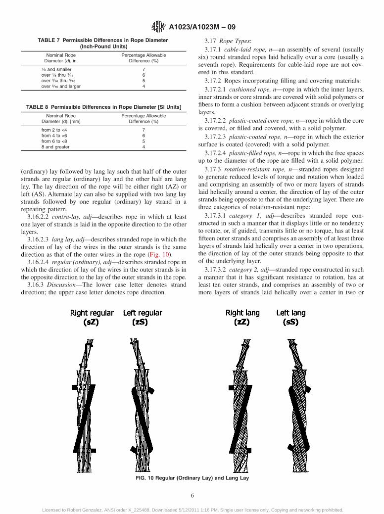
3.7.2 diameter of round rope, n—the diameter (d) thatcircumscribes the rope cross-section. Diameter is expressed ininches or millimeters (Fig. 8).
3.8 Lay Length:3.8.1 rope lay length, n—that distance measured parallel to
the longitudinal rope axis in which the outer strands of astranded rope or the component ropes of a cable-laid rope makeone complete turn (or helix) about the axis of the rope (Fig. 9).
3.8.2 strand lay length, n—that distance measured parallelto the longitudinal strand axis, in which the wire in the strandmakes one complete turn (or helix) about the axis of the strand.The lay length of a strand is that corresponding to the outerlayers of wires (Fig. 9).
Manufacture (Rope)
3.9 Preformation:3.9.1 non-preformed rope, n—rope in which the wires and
strands in the rope will, after removal of any seizing (serving),spring out of the rope formation.
3.9.2 preformed rope, n—rope in which the wires andstrands in the rope will not, after removal of any seizing(serving), spring out of the rope formation.
3.10 prestretching, n—the name given to a process thatresults in the removal of a limited amount of constructionalstretch.
Mechanical Properties
3.11 Rope:3.11.1 actual (measured) breaking force, n—breaking force
obtained using the prescribed test method in Test Method A931or ISO 3108.
3.11.2 calculated breaking force, n—value of breakingforce obtained from the sum of the measured breaking forces ofthe wires in the rope, before rope making, multiplied by themeasured spinning loss factor as determined by the ropemanufacturer’s design.
3.11.3 measured spinning loss factor, n—ratio between themeasured breaking force of the rope and the sum of themeasured breaking forces of the wires, before rope making.
3.11.4 minimum breaking force, n—specified value that theactual (measured) breaking force must meet or exceed in aprescribed test.
3.12 Rope Stretch (Extension):
FIG. 2 Compacted Round Strand–Before and After
FIG. 3 Round Strand
FIG. 4 Triangular Strand
FIG. 5 Lay Direction of Strands for Stranded Ropes
A1023/A1023M – 09
3
Licensed to Robert Gonzalez. ANSI order X_225488. Downloaded 5/12/2011 1:16 PM. Single user license only. Copying and networking prohibited.
3.12.1 constructional stretch (extension), n—amount of ex-tension that is attributed to the initial bedding down of wires
within the strands and the strands within the rope due toloading. Initial extension cannot be determined by calculation.
3.12.2 elastic stretch (extension), n—amount of recoverableextension that follows Hooke’s law within certain limits due toapplication of a load.
3.12.3 permanent stretch (extension), n—non-elastic exten-sion.
3.13 Wire:3.13.1 torsions, n—a measure of wire ductility normally
expressed as the number of 360° revolutions that a wire canwithstand before breakage occurs, using a prescribed testmethod. Torsion requirements are based on the wire diameterand either the wire level, as specified in Specification A1007,or the tensile strength grade, as specified in ISO 2232.
3.13.2 wire tensile strength, n—ratio between the maximumforce obtained in a tensile test and the nominal cross-sectionalarea of the test piece. Requirements for wire tensile strengthare determined by either the wire level, as specified inSpecification A1007, or by the tensile strength grade, asspecified in ISO 2232.
3.13.2.1 tensile strength grade, n—a level of requirementfor tensile strength based on the SI system of units. It isdesignated by a value according to the lower limit of tensilestrength and is used when specifying wire. Values are ex-pressed in N/mm2 (for example, 1960).
3.13.2.2 wire level, n—a level of requirement for tensilestrength based on the inch-pound system of units (for example,Level 3).
Terminology Relating to Ropes
3.14 Rope Classification and Construction:3.14.1 rope classification, n—a grouping of ropes of similar
characteristics on the basis of, for stranded ropes, the numberof strands and their shape, the number of strand layers, thenumber of wires in one strand, the number of outer wires in onestrand, and the number of wire layers in one strand. Forclassification details, refer to Table 2.
3.14.2 rope construction, n—detail and arrangement of thevarious elements of the rope, taking into account the number of
A—Example of Combined Parallel Lay ex. 31WS, 12-(6+6)-6-1B—Filler Construction ex. 25F, 12-6F-6-1C—Seale Construction ex. 19S, 9-9-1D—Warrington Construction ex. 19W, (6+6)-6-1
FIG. 6 Parallel Lay Constructions
FIG. 7 Elements of Stranded Wire Rope
FIG. 8 Diameter of Round Rope
A1023/A1023M – 09
4
Licensed to Robert Gonzalez. ANSI order X_225488. Downloaded 5/12/2011 1:16 PM. Single user license only. Copying and networking prohibited.
strands, and the number of wires in the strand. For constructiondetails, refer to Tables 9–34.
3.14.3 Discussion—Rope construction is designated by list-ing the number of outer strands followed by the number ofwires in each strand and the designation for the type ofconstruction, for example, 6325F. The “3” symbol is read as“by.”
3.15 rope grade, n—a level of requirement for breakingforce that is designated either by a number (for example, 1770,
1960) or a series of letters (for example, IPS, EIP). See 6.3.Rope grade does not imply that the actual tensile strength of thewires in the rope is necessarily of this grade.
3.16 Rope Lay:3.16.1 lay direction of rope, n—the direction right (Z) or left
(S) corresponding to the direction of lay of the outer strands ina stranded rope or the unit ropes in a cable laid rope in relationto the longitudinal axis of the rope.
3.16.2 Lay Types:3.16.2.1 alternate lay, adj—describes stranded rope in
which the type of lay of the outer strands is alternately regular
FIG. 9 Lay Lengths
TABLE 1 Wire Tensile Strength Grades or Levels for GivenRope Grades
Rope GradeWire Tensile Strength Grade or Level
Minimum Maximum
IPS Level 2 / 1570 Level 4 / 1960EIP Level 3 / 1770 Level 5 / 2160EEIP Level 4 / 1960 Level 5 / 21601770 1570 / Level 2 1960 / Level 41960 1770 / Level 3 2160 / Level 52160 1960 / Level 4 2160 / Level 5
TABLE 2 Classification
ClassificationTable Diameter
(in.)Diameter
[mm]SC FC
637 9 10 1⁄4 –11⁄2 6–366319 11 12 1⁄4 –23⁄8 6–606336 13 14 1⁄4 –23⁄8 6–607319 15 1⁄4 –23⁄8 6–607336 16 1⁄4 –23⁄8 6–608319 17 1⁄4 –23⁄8 6–608336 18 1⁄4 –23⁄8 8–608319 SR 19 1⁄2 –11⁄2 12–381937 20 1⁄4 –11⁄2 6–363437 21 1⁄4 –15⁄8 8–403537 22 3⁄8 –15⁄8 8–406312 23 5⁄16 –1 8–256324 24 3⁄8 –2 9.5–516325 TS 25 26 1⁄2 –23⁄8 12–606319 CS 27 3⁄8 –21⁄4 10–566336 CS 28 3⁄8 –21⁄4 10–566319 SW 29 1⁄2 –11⁄2 12–386336 SW 30 1⁄2 –11⁄2 12–381937 CS 31 1⁄4 –1 6–2419319 32 3⁄8 –15⁄8 10–403537 CS 33 7⁄16 –15⁄8 10–40337 CORD 34 1⁄32 0.8737 CORD 34 3⁄64 –3⁄8 1.2–9.57319 CORD 34 1⁄16 –3⁄8 1.6–9.5
Designation key:SR = spin resistantTS = triangular strandCS = compacted strandSW = swaged ropeCORD = small diameter specialty wire ropeSC = steel coreFC = fiber core
TABLE 3 Weight of Coating for Final-Galvanized or Final-CoatedZn-5Al-MM Rope Wire
Diameter of Wire Minimum Weight of Coatingin. [mm] oz/ft2 [kg/m2]
0.025 to 0.047 incl 0.64 to 1.19 incl 0.20 0.06over 0.047 to 0.054 incl over 1.19 to 1.37 incl 0.40 0.12over 0.054 to 0.063 incl over 1.37 to 1.60 incl 0.50 0.15over 0.063 to 0.079 incl over 1.60 to 2.01 incl 0.60 0.18over 0.079 to 0.092 incl over 2.01 to 2.34 incl 0.70 0.21over 0.092 to 0.192 incl over 2.34 to 4.88 incl 0.80 0.24
TABLE 4 Weight of Coating for Drawn-Galvanized or DrawnZn-5Al-MM Rope Wire
Diameter of Wire Minimum Weight of Coatingin. [mm] oz/ft2 [kg/m2]
0.0045 to 0.010 incl 0.11 to 0.25 incl 0.03 0.009Over 0.010 to 0.017 incl Over 0.25 to 0.43 incl 0.05 0.015over 0.017 to 0.028 incl over 0.43 to 0.71 incl 0.10 0.03over 0.028 to 0.060 incl over 0.71 to 1.52 incl 0.20 0.06over 0.060 to 0.090 incl over 1.52 to 2.29 incl 0.30 0.09over 0.090 to 0.140 incl over 2.29 to 3.56 incl 0.40 0.12
TABLE 5 Tolerances on Rope Diameter (Stranded Rope)(Inch-Pound Units)
Nominal RopeDiameter (d), in.
Diameter Tolerancesas aPercentage of Nominal Diameter
thru 1⁄8 -0, +8 %over 1⁄8 thru 3⁄16 -0, +7 %over 3⁄16 thru 5⁄16 -0, +6 %over 5⁄16 and largerA -0, +5 %
A 6312 and 6324 classifications -0, +7 % (Tables 24 and 25)
TABLE 6 Tolerances on Rope Diameter (Stranded Rope)[SI Units]
Nominal RopeDiameter (d), [mm]
Diameter Tolerances as aPercentage of Nominal Diameter
from 2 to <4 -0, +8 %from 4 to <6 -0, +7 %from 6 to <8 -0, +6 %8 and greater -0, +5 %
A1023/A1023M – 09
5
Licensed to Robert Gonzalez. ANSI order X_225488. Downloaded 5/12/2011 1:16 PM. Single user license only. Copying and networking prohibited.
(ordinary) lay followed by lang lay such that half of the outerstrands are regular (ordinary) lay and the other half are langlay. The lay direction of the rope will be either right (AZ) orleft (AS). Alternate lay can also be supplied with two lang laystrands followed by one regular (ordinary) lay strand in arepeating pattern.
3.16.2.2 contra-lay, adj—describes rope in which at leastone layer of strands is laid in the opposite direction to the otherlayers.
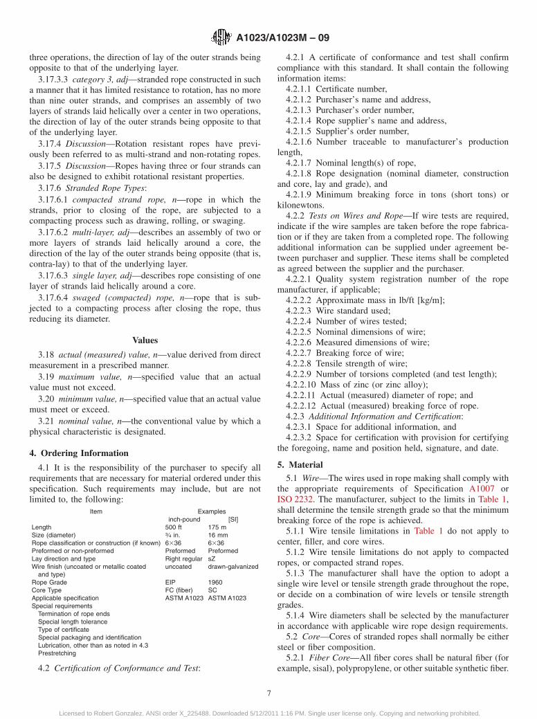
3.16.2.3 lang lay, adj—describes stranded rope in which thedirection of lay of the wires in the outer strands is the samedirection as that of the outer wires in the rope (Fig. 10).
3.16.2.4 regular (ordinary), adj—describes stranded rope inwhich the direction of lay of the wires in the outer strands is inthe opposite direction to the lay of the outer strands in the rope.
3.16.3 Discussion—The lower case letter denotes stranddirection; the upper case letter denotes rope direction.
3.17 Rope Types:3.17.1 cable-laid rope, n—an assembly of several (usually
six) round stranded ropes laid helically over a core (usually aseventh rope). Requirements for cable-laid rope are not cov-ered in this standard.
3.17.2 Ropes incorporating filling and covering materials:3.17.2.1 cushioned rope, n—rope in which the inner layers,
inner strands or core strands are covered with solid polymers orfibers to form a cushion between adjacent strands or overlyinglayers.
3.17.2.2 plastic-coated core rope, n—rope in which the coreis covered, or filled and covered, with a solid polymer.
3.17.2.3 plastic-coated rope, n—rope in which the exteriorsurface is coated (covered) with a solid polymer.
3.17.2.4 plastic-filled rope, n—rope in which the free spacesup to the diameter of the rope are filled with a solid polymer.
3.17.3 rotation-resistant rope, n—stranded ropes designedto generate reduced levels of torque and rotation when loadedand comprising an assembly of two or more layers of strandslaid helically around a center, the direction of lay of the outerstrands being opposite to that of the underlying layer. There arethree categories of rotation-resistant rope:
3.17.3.1 category 1, adj—describes stranded rope con-structed in such a manner that it displays little or no tendencyto rotate, or, if guided, transmits little or no torque, has at leastfifteen outer strands and comprises an assembly of at least threelayers of strands laid helically over a center in two operations,the direction of lay of the outer strands being opposite to thatof the underlying layer.
3.17.3.2 category 2, adj—stranded rope constructed in sucha manner that it has significant resistance to rotation, has atleast ten outer strands, and comprises an assembly of two ormore layers of strands laid helically over a center in two or
TABLE 7 Permissible Differences in Rope Diameter(Inch-Pound Units)
Nominal RopeDiameter (d), in.
Percentage AllowableDifference (%)
1⁄8 and smaller 7over 1⁄8 thru 3⁄16 6over 3⁄16 thru 5⁄16 5over 5⁄16 and larger 4
TABLE 8 Permissible Differences in Rope Diameter [SI Units]
Nominal RopeDiameter (d), [mm]
Percentage AllowableDifference (%)
from 2 to <4 7from 4 to <6 6from 6 to <8 58 and greater 4
FIG. 10 Regular (Ordinary Lay) and Lang Lay
A1023/A1023M – 09
6
Licensed to Robert Gonzalez. ANSI order X_225488. Downloaded 5/12/2011 1:16 PM. Single user license only. Copying and networking prohibited.
three operations, the direction of lay of the outer strands beingopposite to that of the underlying layer.
3.17.3.3 category 3, adj—stranded rope constructed in sucha manner that it has limited resistance to rotation, has no morethan nine outer strands, and comprises an assembly of twolayers of strands laid helically over a center in two operations,the direction of lay of the outer strands being opposite to thatof the underlying layer.
3.17.4 Discussion—Rotation resistant ropes have previ-ously been referred to as multi-strand and non-rotating ropes.
3.17.5 Discussion—Ropes having three or four strands canalso be designed to exhibit rotational resistant properties.
3.17.6 Stranded Rope Types:3.17.6.1 compacted strand rope, n—rope in which the
strands, prior to closing of the rope, are subjected to acompacting process such as drawing, rolling, or swaging.
3.17.6.2 multi-layer, adj—describes an assembly of two ormore layers of strands laid helically around a core, thedirection of the lay of the outer strands being opposite (that is,contra-lay) to that of the underlying layer.
3.17.6.3 single layer, adj—describes rope consisting of onelayer of strands laid helically around a core.
3.17.6.4 swaged (compacted) rope, n—rope that is sub-jected to a compacting process after closing the rope, thusreducing its diameter.
Values
3.18 actual (measured) value, n—value derived from directmeasurement in a prescribed manner.
3.19 maximum value, n—specified value that an actualvalue must not exceed.
3.20 minimum value, n—specified value that an actual valuemust meet or exceed.
3.21 nominal value, n—the conventional value by which aphysical characteristic is designated.
4. Ordering Information
4.1 It is the responsibility of the purchaser to specify allrequirements that are necessary for material ordered under thisspecification. Such requirements may include, but are notlimited to, the following:
Item Examplesinch-pound [SI]
Length 500 ft 175 mSize (diameter) 3⁄4 in. 16 mmRope classification or construction (if known) 6336 6336Preformed or non-preformed Preformed PreformedLay direction and type Right regular sZWire finish (uncoated or metallic coated
and type)uncoated drawn-galvanized
Rope Grade EIP 1960Core Type FC (fiber) SCApplicable specification ASTM A1023 ASTM A1023Special requirements
Termination of rope endsSpecial length toleranceType of certificateSpecial packaging and identificationLubrication, other than as noted in 4.3Prestretching
4.2 Certification of Conformance and Test:
4.2.1 A certificate of conformance and test shall confirmcompliance with this standard. It shall contain the followinginformation items:
4.2.1.1 Certificate number,4.2.1.2 Purchaser’s name and address,4.2.1.3 Purchaser’s order number,4.2.1.4 Rope supplier’s name and address,4.2.1.5 Supplier’s order number,4.2.1.6 Number traceable to manufacturer’s production
length,4.2.1.7 Nominal length(s) of rope,4.2.1.8 Rope designation (nominal diameter, construction
and core, lay and grade), and4.2.1.9 Minimum breaking force in tons (short tons) or
kilonewtons.4.2.2 Tests on Wires and Rope—If wire tests are required,
indicate if the wire samples are taken before the rope fabrica-tion or if they are taken from a completed rope. The followingadditional information can be supplied under agreement be-tween purchaser and supplier. These items shall be completedas agreed between the supplier and the purchaser.
4.2.2.1 Quality system registration number of the ropemanufacturer, if applicable;
4.2.2.2 Approximate mass in lb/ft [kg/m];4.2.2.3 Wire standard used;4.2.2.4 Number of wires tested;4.2.2.5 Nominal dimensions of wire;4.2.2.6 Measured dimensions of wire;4.2.2.7 Breaking force of wire;4.2.2.8 Tensile strength of wire;4.2.2.9 Number of torsions completed (and test length);4.2.2.10 Mass of zinc (or zinc alloy);4.2.2.11 Actual (measured) diameter of rope; and4.2.2.12 Actual (measured) breaking force of rope.4.2.3 Additional Information and Certification:4.2.3.1 Space for additional information, and4.2.3.2 Space for certification with provision for certifying
the foregoing, name and position held, signature, and date.
5. Material
5.1 Wire—The wires used in rope making shall comply withthe appropriate requirements of Specification A1007 orISO 2232. The manufacturer, subject to the limits in Table 1,shall determine the tensile strength grade so that the minimumbreaking force of the rope is achieved.
5.1.1 Wire tensile limitations in Table 1 do not apply tocenter, filler, and core wires.
5.1.2 Wire tensile limitations do not apply to compactedropes, or compacted strand ropes.
5.1.3 The manufacturer shall have the option to adopt asingle wire level or tensile strength grade throughout the rope,or decide on a combination of wire levels or tensile strengthgrades.
5.1.4 Wire diameters shall be selected by the manufacturerin accordance with applicable wire rope design requirements.
5.2 Core—Cores of stranded ropes shall normally be eithersteel or fiber composition.
5.2.1 Fiber Core—All fiber cores shall be natural fiber (forexample, sisal), polypropylene, or other suitable synthetic fiber.
A1023/A1023M – 09
7
Licensed to Robert Gonzalez. ANSI order X_225488. Downloaded 5/12/2011 1:16 PM. Single user license only. Copying and networking prohibited.
The cores shall be of uniform hardness, effectively supportingthe strands. Natural fiber cores shall be treated with animpregnating compound free from acid. Fiber cores larger than5⁄32-in. (4-mm) diameter shall be doubly closed.
5.2.2 Steel Core—Steel main cores shall be either an inde-pendent wire rope (IWRC) or a wire strand (WSC). Steel coresof single layer ropes larger than 7⁄16-in. (12-mm) diameter shallbe independent wire ropes (IWRC), unless specified otherwise.Steel cores shall be lubricated. Cores closed in one operation(parallel lay) with the outer strands of the rope may bespecified by agreement between the supplier and the purchaser.
5.3 Lubricant—All wire rope, unless otherwise specified,shall be lubricated and impregnated in the manufacturingprocess with a suitable lubricant selected by the manufacturer.Stranding lubricants used for fiber core ropes shall be compat-ible with the impregnating compound of the fiber core.
6. Rope Properties and Tolerances
6.1 Classification—The rope classification shall be speci-fied by the purchaser and shall normally be one of thosecovered in Table 2 although other classifications and construc-tions are available by agreement between the supplier andpurchaser.
NOTE 2—Where only the rope classification is specified by the pur-chaser, the manufacturer shall determine the construction.
6.2 Rope Core—Steel core (SC) shall be supplied unlessotherwise specified. The manufacturer shall determine coreconstruction. Cores with inserts or solid polymer cores aresubject to agreement between the supplier and purchaser.
6.3 Rope Grade—The rope grade shall be one of thefollowing although other grades are available by agreementbetween the supplier and purchaser.
6.3.1 The listed rope grades for the following inch-poundunits are shown in the indicated tables:
6.3.1.1 IPS—Tables 10–21, Tables 24–276.3.1.2 EIP—Tables 10–21, Tables 26–336.3.1.3 EEIP—Tables 12–20, Tables 26–29, Tables 32 and
336.3.2 Rope Grades for the following SI units are shown in
the indicated tables:6.3.2.1 1770—Table 10–19, Tables 21–236.3.2.2 1960—Tables 10–19, Tables 21–23, Tables 28 and
29, Tables 32–346.3.2.3 2160—Tables 12–19, Table 23, Tables 28 and 29,
Tables 32–346.4 Wire Finish—Unless otherwise specified, wire ropes
will be furnished with uncoated wires. For wire ropes re-quested with metallic coated wires, the wires shall be galva-nized unless otherwise specified by the purchaser.
6.4.1 Final-Galvanized Rope—All outer wires shall besupplied as final-galvanized. Inner, filler, and center wires shallbe supplied as final-galvanized or drawn-galvanized. Minimumweight of coating for galvanized wire shall be as specified inTables 3 and 4.
6.4.1.1 Final-galvanized rope shall be supplied with mini-mum breaking forces 10 % lower than those listed inTables 9–34, except for Table 21 and Table 22.
6.4.1.2 Final-Coated Zn-5Al-MM—Wires of final-coatedZn-5Al-MM may be substituted for final-galvanized wire at theoption of the manufacturer. Minimum weight of coating shallbe as specified in Table 3.
6.4.2 Drawn-Galvanized (Zinc Coated) Rope—All thewires shall be galvanized (zinc coated), including those of anysteel core. Minimum weight of coating shall be as specified inTable 4.
6.4.2.1 Drawn galvanized rope shall be supplied with mini-mum breaking forces no less than those listed in Tables 9–34.
6.4.2.2 Drawn-Zn-5Al-MM—Wires of drawn-Zn–5Al-MMmay be substituted for drawn-galvanized wire at the option ofthe manufacturer. Minimum weight of coating shall be asspecified in Table 4.
6.5 Direction and Type of Rope Lay—The direction andtype of rope lay shall be as specified by the purchaser and shallbe one of the following:
Right regular (ordinary) lay (sZ)Left regular (ordinary) lay (zS)Right lang lay (zZ)Left lang lay (sS)Right alternate lay (AZ)Left alternate lay (AS)
Right regular (ordinary) lay will be supplied for six, seven,and eight-strand constructions unless otherwise specified bythe purchaser.
6.6 Dimensions:6.6.1 Rope Diameter—The nominal diameter shall be as
specified by the purchaser and shall be the dimension by whichthe rope is designated.
6.6.1.1 Tolerance on Rope Diameter—When measured inaccordance with 8.6.1, the actual diameter shall not vary fromthe nominal diameter by more than the tolerances specified inTable 5 or Table 6. For small diameter specialty cord withdiameters from 1⁄32 in. [0.8 mm] to 3⁄8 in. [10 mm] inclusive,diameter tolerances shall be as specified in Table 9.
6.6.1.2 Permissible Differences in Diameter—The differ-ence between any two of the four measurements taken inaccordance with 8.6.1, and expressed as a percentage of thenominal diameter, shall not exceed the values given in Table 7or Table 8.
6.6.2 Lay Length:6.6.2.1 For single layer ropes of 637 class, the lay length of
the finish rope shall not exceed 8 times the nominal ropediameter.
6.6.2.2 For other single layer ropes with round strands,except for 3 or 4 strand ropes, and multi-layer ropes with roundor shaped strands, the length of lay of the finished rope shallnot exceed 7.25 times the nominal rope diameter.
6.6.2.3 For single layer ropes with shaped strands, forexample, flattened (triangular) strand, the length of lay of thefinished rope shall not exceed 10 times the nominal ropediameter.
6.7 Mechanical Properties:6.7.1 Breaking Force—Values for minimum breaking force
for the more common classes of rope are specified inTables 9–34 of this standard.
A1023/A1023M – 09
8
Licensed to Robert Gonzalez. ANSI order X_225488. Downloaded 5/12/2011 1:16 PM. Single user license only. Copying and networking prohibited.
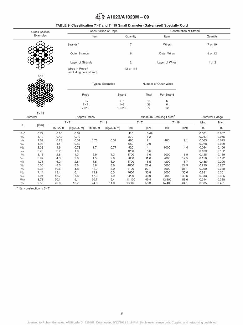
TABLE 9 Classification 737 and 7319 Small Diameter (Galvanized) Specialty Cord
Cross SectionExamples
Construction of Rope Construction of Strand
Item Quantity Item Quantity
737
7319
StrandsA 7 Wires 7 or 19
Outer Strands 6 Outer Wires 6 or 12
Layer of Strands 2 Layer of Wires 1 or 2
Wires in RopeA
(excluding core strand)42 or 114
Typical Examples Number of Outer Wires
Rope Strand Total Per Strand
337737
7319
1–61–6
1–6/12
183672
6612
Diameter Approx. Mass Minimum Breaking ForceA Diameter Range
in. [mm]737 7319 737 7319 Min. Max.
lb/100 ft [kg/30.5 m] lb/100 ft [kg/30.5 m] lbs [kN] lbs [kN] in. in.
1⁄32A 0.79 0.16 0.07 110 0.49 0.031 0.037
3⁄64 1.19 0.42 0.19 270 1.2 0.047 0.0551⁄16 1.59 0.75 0.34 0.75 0.34 480 2.1 480 2.1 0.063 0.0735⁄64 1.98 1.1 0.50 650 2.9 0.078 0.0893⁄32 2.38 1.6 0.73 1.7 0.77 920 4.1 1000 4.4 0.094 0.1067⁄64 2.78 2.2 1.0 1260 5.6 0.109 0.1221⁄8 3.18 2.8 1.3 2.9 1.3 1700 7.6 2000 8.9 0.125 0.1395⁄32 3.97 4.3 2.0 4.5 2.0 2600 11.6 2800 12.5 0.156 0.1723⁄16 4.76 6.2 2.8 6.5 3.0 3700 16.5 4200 18.7 0.188 0.2067⁄32 5.56 8.3 3.8 8.6 3.9 4800 21.4 5600 24.9 0.219 0.2371⁄4 6.35 10.6 4.8 11.0 5.0 6100 27.1 7000 31.1 0.250 0.2689⁄32 7.14 13.4 6.1 13.9 6.3 7600 33.8 8000 35.6 0.281 0.3015⁄16 7.94 16.7 7.6 17.3 7.9 9200 40.9 9800 43.6 0.313 0.33511⁄32 8.73 20.1 9.1 20.7 9.4 11 100 49.4 12 500 55.6 0.344 0.3683⁄8 9.53 23.6 10.7 24.3 11.0 13 100 58.3 14 400 64.1 0.375 0.401
A 1⁄32 construction is 337.
A1023/A1023M – 09
9
Licensed to Robert Gonzalez. ANSI order X_225488. Downloaded 5/12/2011 1:16 PM. Single user license only. Copying and networking prohibited.
6.7.1.1 The minimum breaking force for other classes andconstructions not covered by the tables, shall be agreed uponby the manufacturer and the purchaser.
6.7.1.2 Wire ropes with minimum breaking forces less thanthose allowed in this specification may be accepted by prioragreement between the supplier and purchaser and shall beregarded as beyond the scope of this specification.
6.7.2 Mass—The (approximate) nominal rope mass shall beas given in Tables 9–34 or as specified by the manufacturer.
6.7.3 Length—The actual length of rope supplied, expressedin feet or meters, shall be the specified length subject to thefollowing limits of tolerance:
(a) Up to and including 1300 ft [400 m]: +5.0 % ofspecified length,
(b) Over 1300 ft up to 3280 ft [400 m to 1000 m]: +66 ft[20 m], and
(c) Over 3280 ft [1000 m]: +2.0 % of specified length.
NOTE 3—The rope shall be measured under no load. Ropes requiredwith more restrictive length tolerance shall be agreed upon by the supplierand purchaser.
7. Rope Workmanship and Finish
7.1 Strand:7.1.1 Strand wires shall be tight and uniform. All the wire
layers in a strand shall have the same direction of lay. The laylengths of corresponding wire layers in strands of the same sizeshall be uniform.
7.1.2 Center wires and fiber centers of strands shall be of asize to provide sufficient support to enable the covering wiresto be evenly laid.
7.2 Rope—The rope shall be uniformly made and thestrands shall lie tightly on the core or the underlying strands.
7.2.1 The core of a stranded rope, except for swaged(compacted) ropes, shall be designed so that in a new ropeunder no load there is clearance between the outer strands.
7.2.2 Rope ends that have no end fittings shall be so securedas to maintain the integrity of the rope and prevent itsunraveling.
7.3 Wire Joints:7.3.1 Wires over 0.015 in. [0.4 mm] in diameter shall have
their ends joined by soldering, brazing, or welding.7.3.2 Wires up to and including 0.015 in. [0.4 mm] diameter
may be joined by soldering, brazing, welding, twisting, or byends being simply inserted into the strand’s formation.
7.3.3 The minimum distance between joints in a strand shallbe 18 times the nominal rope diameter.
7.4 Preformation—Stranded ropes shall be preformed un-less otherwise specified, except that multi-layer ropes, includ-ing rotation-resistant and low-rotation ropes, may be non-preformed.
7.5 Prestretching—Stranded ropes are not prestretched un-less otherwise specified. When specified, ropes may be pre-stretched using either a process of static or dynamic loading.Prestretch loads shall not exceed 55 % of the minimumbreaking force for the rope.
NOTE 4—Example of static prestretching practice: Rope is subjected tothree cycles of tensile loading to 40 % of the ropes minimum breaking
force for 5 min, returning to 5 % of the minimum breaking force betweencycles. After the last cycle, the tensile load is completely released.
8. Testing and Compliance
General
8.1 Wire ropes manufactured in accordance with this speci-fication shall be capable of meeting all the appropriate require-ments as specified in 8.2. The manufacturer shall be able todemonstrate compliance with this specification by either:
8.1.1 Testing each production length in accordance with 8.2,or
8.1.2 Operating a quality assurance system that includes asampling program that meets the following requirements as aminimum:
8.1.2.1 For each size and grade of a given rope construction,the manufacturer shall present evidence from testing, if re-quested by the purchaser, of a minimum of three productionlengths representing the current design. The purpose of thesetests is to assure the manufacturer’s ability to produce a ropethat conforms to the minimum requirements as defined in thisspecification. Periodic acceptance tests are successfully com-pleted on a sample taken from a minimum of every twentiethproduction length.
8.1.2.2 Manufacturers complying with all requirements of8.1.2 may use calculated breaking force to verify compliancewith requirements for an individual production length notincluded in sample testing.
8.2 Any change in design requires that the tests specified in8.1.2 be repeated on the modified rope. However, if the samedesign, apart from the wire tensile grades, is used for ropes ofa lower grade than the one which has successfully passed thetests specified in 8.1.2, it shall not be necessary to repeat thetests on the lower grade rope(s).
8.3 For the purposes of this specification, a productionlength is regarded as that length of rope manufactured in onecontinuous operation from one loading of the closing machinecomprising strands, each of which has been produced in onecontinuous operation on the stranding machine. A productionlength may comprise one or more reels of rope.
NOTE 5—Examples of quality assurance systems are API Q1, ANSI/ASQC Q9002 and ISO 9002.
Acceptance Tests
8.4 Test Piece—When required by 8.1, one test piece shallbe taken from each production length.
8.5 Test Verification—When requested, the manufacturershall allow the purchaser or his representative the opportunityto witness acceptance tests (when these are performed), or toexamine test records, to verify compliance with this specifica-tion. Test lengths required by the purchaser should be orderedas additional lengths.
8.6 Rope:8.6.1 Diameter—Measurements for diameter shall be taken
on a straight portion of the rope without tension, at twopositions spaced at least three feet (or one meter) apart, and ateach position two diameters at right angles shall be measured.The average of these four measurements shall be within thetolerances given in Tables 5 and 6 of this specification. The
A1023/A1023M – 09
10
Licensed to Robert Gonzalez. ANSI order X_225488. Downloaded 5/12/2011 1:16 PM. Single user license only. Copying and networking prohibited.
permissible differences between any two individual diametermeasurements are given in Tables 7 and 8.
NOTE 6—In case of dispute concerning oversize diameter, the rope shallbe measured under a tension not exceeding 20 % of the minimumbreaking force. If the measurements from this test are within the specifiedtolerances, the rope shall be deemed to be within the specified size.
8.6.2 Breaking Force—When measured in accordance withthe method specified in Test Method A931 or ISO 3108, theactual (measured) breaking force obtained shall be equal to orgreater than the minimum breaking force required by thisspecification. If the minimum breaking force is not achieved,up to three additional tests shall be permitted. At least one ofthe additional tests shall achieve the minimum breaking forcespecified. Tables 9–34 show the minimum breaking forces ofthe more common classes, sizes, and grades of ropes:
8.6.2.1 Minimum breaking forces listed apply to uncoatedor drawn-galvanized ropes.
8.6.2.2 Minimum breaking forces for final-galvanized ropesare 10 % lower than values listed, except for Tables 21 and 22.
8.6.2.3 Minimum breaking force values for IPS, EIP andEEIP are given in short tons of 2000 pounds.
8.7 Rope Wires:8.7.1 General—Wires shall be tested for diameter, tensile
strength, torsions, and, where applicable, metallic coating inaccordance with the methods in Specification A1007 orISO 2232. The manufacturer shall have the option to test wireseither before or after fabrication of the rope.
NOTE 7—After fabrication wire testing is not applicable to compactedstrand ropes or swaged (compacted) ropes.
8.7.2 Sampling—All main wires from the equivalent of onecomplete strand of each layer, strand diameter and strandconstruction, including steel rope core, shall be tested. If thereare more than eight strands of one diameter in one layer, thentwo strands of that diameter shall be tested.
8.7.3 For the purpose of evaluating the test results, the ropemanufacturer shall record the nominal diameters and tensilegrades of the wires.
8.7.3.1 The sample selected shall be of sufficient length toallow for retest.
8.7.3.2 The wires shall be selected at random.8.7.3.3 Filler wires and center wires shall be excluded from
this test.
8.7.4 Levels of Acceptance:8.7.4.1 Wire before Fabrication—Wire samples tested be-
fore fabrication shall meet the requirements for the size andgrade (level) specified by the supplier and as found in theappropriate wire specification.
8.7.4.2 Wire after Fabrication—For each requirement, amaximum of 5 % of wires tested is permitted to lie outside thevalues specified, rounded to the nearest whole number of wires.Failure of the same wire to satisfy more than one requirementshall be considered as a single failure.
(a) Diameter—The diameter of 5 % of the wires mayexceed, by up to 50 %, the specified tolerance for the nominaldiameter.
(b) Tensile Strength—When tested in accordance with therequirements of Specification A1007, the measured valuesshall be within the tolerance specified with an additionaltolerance of 7000 psi [50 N/mm2] below the minimum value.The measured value of wire diameters less than 0.020 in. [0.5mm] shall be greater than the minimum values specified in theappropriate wire specification.
(c) Torsion—When tested in accordance with the require-ments of Specification A1007, the measured values of wires of0.020 in. [0.5 mm] diameter and greater shall be at least 85 %of the values specified, rounded down to the next wholenumber. The measured value of wire diameters less than 0.020in. [0.5 mm] shall be greater than the minimum valuesspecified.
9. Packaging and Identification
9.1 Packaging—Unless otherwise specified by the pur-chaser, ropes shall be supplied in coils or on reels at thediscretion of the manufacturer.
9.2 Identification—Each package of rope shall be legiblyidentified with the following information, as a minimum:
9.2.1 Rope supplier and address,9.2.2 Rope length and description, and9.2.3 Number traceable to manufacturer’s production
length.
10. Keywords
10.1 aircraft cable; cable; steel cable; steel rope; utilitycable; wire rope
A1023/A1023M – 09
11
Licensed to Robert Gonzalez. ANSI order X_225488. Downloaded 5/12/2011 1:16 PM. Single user license only. Copying and networking prohibited.
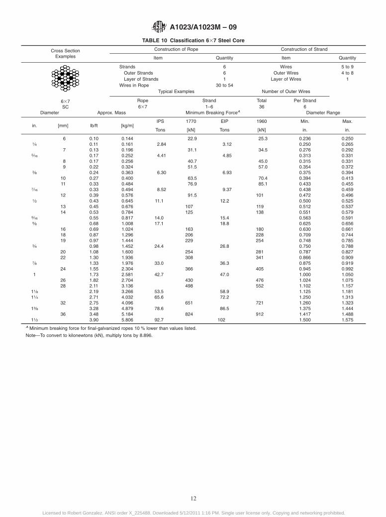
TABLE 10 Classification 637 Steel Core
Cross SectionExamples
Construction of Rope Construction of Strand
Item Quantity Item Quantity
637SC
Strands 6 Wires 5 to 9Outer Strands 6 Outer Wires 4 to 8Layer of Strands 1 Layer of Wires 1
Wires in Rope 30 to 54Typical Examples Number of Outer Wires
Rope Strand Total Per Strand637 1–6 36 6
Diameter Approx. Mass Minimum Breaking ForceA Diameter Range
in. [mm] lb/ft [kg/m]IPS 1770 EIP 1960 Min. Max.
Tons [kN] Tons [kN] in. in.
6 0.10 0.144 22.9 25.3 0.236 0.2501⁄4 0.11 0.161 2.84 3.12 0.250 0.265
7 0.13 0.196 31.1 34.5 0.276 0.2925⁄16 0.17 0.252 4.41 4.85 0.313 0.331
8 0.17 0.256 40.7 45.0 0.315 0.3319 0.22 0.324 51.5 57.0 0.354 0.372
3⁄8 0.24 0.363 6.30 6.93 0.375 0.39410 0.27 0.400 63.5 70.4 0.394 0.41311 0.33 0.484 76.9 85.1 0.433 0.455
7⁄16 0.33 0.494 8.52 9.37 0.438 0.45912 0.39 0.576 91.5 101 0.472 0.496
1⁄2 0.43 0.645 11.1 12.2 0.500 0.52513 0.45 0.676 107 119 0.512 0.53714 0.53 0.784 125 138 0.551 0.579
9⁄16 0.55 0.817 14.0 15.4 0.563 0.5915⁄8 0.68 1.008 17.1 18.8 0.625 0.656
16 0.69 1.024 163 180 0.630 0.66118 0.87 1.296 206 228 0.709 0.74419 0.97 1.444 229 254 0.748 0.785
3⁄4 0.98 1.452 24.4 26.8 0.750 0.78820 1.08 1.600 254 281 0.787 0.82722 1.30 1.936 308 341 0.866 0.909
7⁄8 1.33 1.976 33.0 36.3 0.875 0.91924 1.55 2.304 366 405 0.945 0.992
1 1.73 2.581 42.7 47.0 1.000 1.05026 1.82 2.704 430 476 1.024 1.07528 2.11 3.136 498 552 1.102 1.157
11⁄8 2.19 3.266 53.5 58.9 1.125 1.18111⁄4 2.71 4.032 65.6 72.2 1.250 1.313
32 2.75 4.096 651 721 1.260 1.32313⁄8 3.28 4.879 78.6 86.5 1.375 1.444
36 3.48 5.184 824 912 1.417 1.48811⁄2 3.90 5.806 92.7 102 1.500 1.575
A Minimum breaking force for final-galvanized ropes 10 % lower than values listed.
Note—To convert to kilonewtons (kN), multiply tons by 8.896.
A1023/A1023M – 09
12
Licensed to Robert Gonzalez. ANSI order X_225488. Downloaded 5/12/2011 1:16 PM. Single user license only. Copying and networking prohibited.
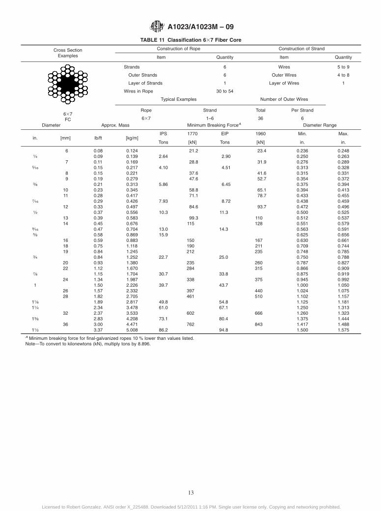
TABLE 11 Classification 637 Fiber Core
Cross SectionExamples
Construction of Rope Construction of Strand
Item Quantity Item Quantity
637FC
Strands 6 Wires 5 to 9
Outer Strands 6 Outer Wires 4 to 8
Layer of Strands 1 Layer of Wires 1
Wires in Rope 30 to 54
Typical Examples Number of Outer Wires
Rope Strand Total Per Strand
637 1–6 36 6
Diameter Approx. Mass Minimum Breaking ForceA Diameter Range
in. [mm] lb/ft [kg/m]IPS 1770 EIP 1960 Min. Max.
Tons [kN] Tons [kN] in. in.
6 0.08 0.124 21.2 23.4 0.236 0.2481⁄4 0.09 0.139 2.64 2.90 0.250 0.263
7 0.11 0.169 28.8 31.9 0.276 0.2895⁄16 0.15 0.217 4.10 4.51 0.313 0.328
8 0.15 0.221 37.6 41.6 0.315 0.3319 0.19 0.279 47.6 52.7 0.354 0.372
3⁄8 0.21 0.313 5.86 6.45 0.375 0.39410 0.23 0.345 58.8 65.1 0.394 0.41311 0.28 0.417 71.1 78.7 0.433 0.455
7⁄16 0.29 0.426 7.93 8.72 0.438 0.45912 0.33 0.497 84.6 93.7 0.472 0.496
1⁄2 0.37 0.556 10.3 11.3 0.500 0.52513 0.39 0.583 99.3 110 0.512 0.53714 0.45 0.676 115 128 0.551 0.579
9⁄16 0.47 0.704 13.0 14.3 0.563 0.5915⁄8 0.58 0.869 15.9 0.625 0.656
16 0.59 0.883 150 167 0.630 0.66118 0.75 1.118 190 211 0.709 0.74419 0.84 1.245 212 235 0.748 0.785
3⁄4 0.84 1.252 22.7 25.0 0.750 0.78820 0.93 1.380 235 260 0.787 0.82722 1.12 1.670 284 315 0.866 0.909
7⁄8 1.15 1.704 30.7 33.8 0.875 0.91924 1.34 1.987 338 375 0.945 0.992
1 1.50 2.226 39.7 43.7 1.000 1.05026 1.57 2.332 397 440 1.024 1.07528 1.82 2.705 461 510 1.102 1.157
11⁄8 1.89 2.817 49.8 54.8 1.125 1.18111⁄4 2.34 3.478 61.0 67.1 1.250 1.313
32 2.37 3.533 602 666 1.260 1.32313⁄8 2.83 4.208 73.1 80.4 1.375 1.444
36 3.00 4.471 762 843 1.417 1.48811⁄2 3.37 5.008 86.2 94.8 1.500 1.575
A Minimum breaking force for final-galvanized ropes 10 % lower than values listed.Note—To convert to kilonewtons (kN), multiply tons by 8.896.
A1023/A1023M – 09
13
Licensed to Robert Gonzalez. ANSI order X_225488. Downloaded 5/12/2011 1:16 PM. Single user license only. Copying and networking prohibited.
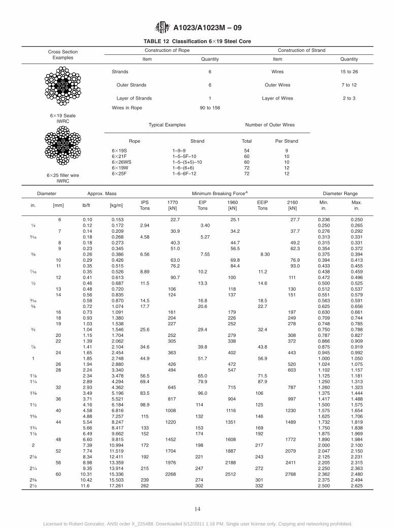
TABLE 12 Classification 6319 Steel Core
Cross SectionExamples
Construction of Rope Construction of Strand
Item Quantity Item Quantity
6319 SealeIWRC
6325 filler wireIWRC
Strands 6 Wires 15 to 26
Outer Strands 6 Outer Wires 7 to 12
Layer of Strands 1 Layer of Wires 2 to 3
Wires in Rope 90 to 156
Typical Examples Number of Outer Wires
Rope Strand Total Per Strand
6319S6321F6326WS6319W6325F
1–9–91–5–5F–101–5–(5+5)–101–6–(6+6)1–6–6F–12
5460607272
910101212
Diameter Approx. Mass Minimum Breaking ForceA Diameter Range
in. [mm] lb/ft [kg/m]IPS 1770 EIP 1960 EEIP 2160 Min. Max.Tons [kN] Tons [kN] Tons [kN] in. in.
6 0.10 0.153 22.7 25.1 27.7 0.236 0.2501⁄4 0.12 0.172 2.94 3.40 0.250 0.265
7 0.14 0.209 30.9 34.2 37.7 0.276 0.2925⁄16 0.18 0.268 4.58 5.27 0.313 0.331
8 0.18 0.273 40.3 44.7 49.2 0.315 0.3319 0.23 0.345 51.0 56.5 62.3 0.354 0.372
3⁄8 0.26 0.386 6.56 7.55 8.30 0.375 0.39410 0.29 0.426 63.0 69.8 76.9 0.394 0.41311 0.35 0.515 76.2 84.4 93.0 0.433 0.455
7⁄16 0.35 0.526 8.89 10.2 11.2 0.438 0.45912 0.41 0.613 90.7 100 111 0.472 0.496
1⁄2 0.46 0.687 11.5 13.3 14.6 0.500 0.52513 0.48 0.720 106 118 130 0.512 0.53714 0.56 0.835 124 137 151 0.551 0.579
9⁄16 0.58 0.870 14.5 16.8 18.5 0.563 0.5915⁄8 0.72 1.074 17.7 20.6 22.7 0.625 0.656
16 0.73 1.091 161 179 197 0.630 0.66118 0.93 1.380 204 226 249 0.709 0.74419 1.03 1.538 227 252 278 0.748 0.785
3⁄4 1.04 1.546 25.6 29.4 32.4 0.750 0.78820 1.15 1.704 252 279 308 0.787 0.82722 1.39 2.062 305 338 372 0.866 0.909
7⁄8 1.41 2.104 34.6 39.8 43.8 0.875 0.91924 1.65 2.454 363 402 443 0.945 0.992
1 1.85 2.748 44.9 51.7 56.9 1.000 1.05026 1.94 2.880 426 472 520 1.024 1.07528 2.24 3.340 494 547 603 1.102 1.157
11⁄8 2.34 3.478 56.5 65.0 71.5 1.125 1.18111⁄4 2.89 4.294 69.4 79.9 87.9 1.250 1.313
32 2.93 4.362 645 715 787 1.260 1.32313⁄8 3.49 5.196 83.5 96.0 106 1.375 1.444
36 3.71 5.521 817 904 997 1.417 1.48811⁄2 4.16 6.184 98.9 114 125 1.500 1.575
40 4.58 6.816 1008 1116 1230 1.575 1.65415⁄8 4.88 7.257 115 132 146 1.625 1.706
44 5.54 8.247 1220 1351 1489 1.732 1.81913⁄4 5.66 8.417 133 153 169 1.750 1.83817⁄8 6.49 9.662 152 174 192 1.875 1.969
48 6.60 9.815 1452 1608 1772 1.890 1.9842 7.39 10.994 172 198 217 2.000 2.100
52 7.74 11.519 1704 1887 2079 2.047 2.15021⁄8 8.34 12.411 192 221 243 2.125 2.231
56 8.98 13.359 1976 2188 2411 2.205 2.31521⁄4 9.35 13.914 215 247 272 2.250 2.363
60 10.31 15.336 2268 2512 2768 2.362 2.48023⁄8 10.42 15.503 239 274 301 2.375 2.49421⁄2 11.6 17.261 262 302 332 2.500 2.625
A1023/A1023M – 09
14
Licensed to Robert Gonzalez. ANSI order X_225488. Downloaded 5/12/2011 1:16 PM. Single user license only. Copying and networking prohibited.
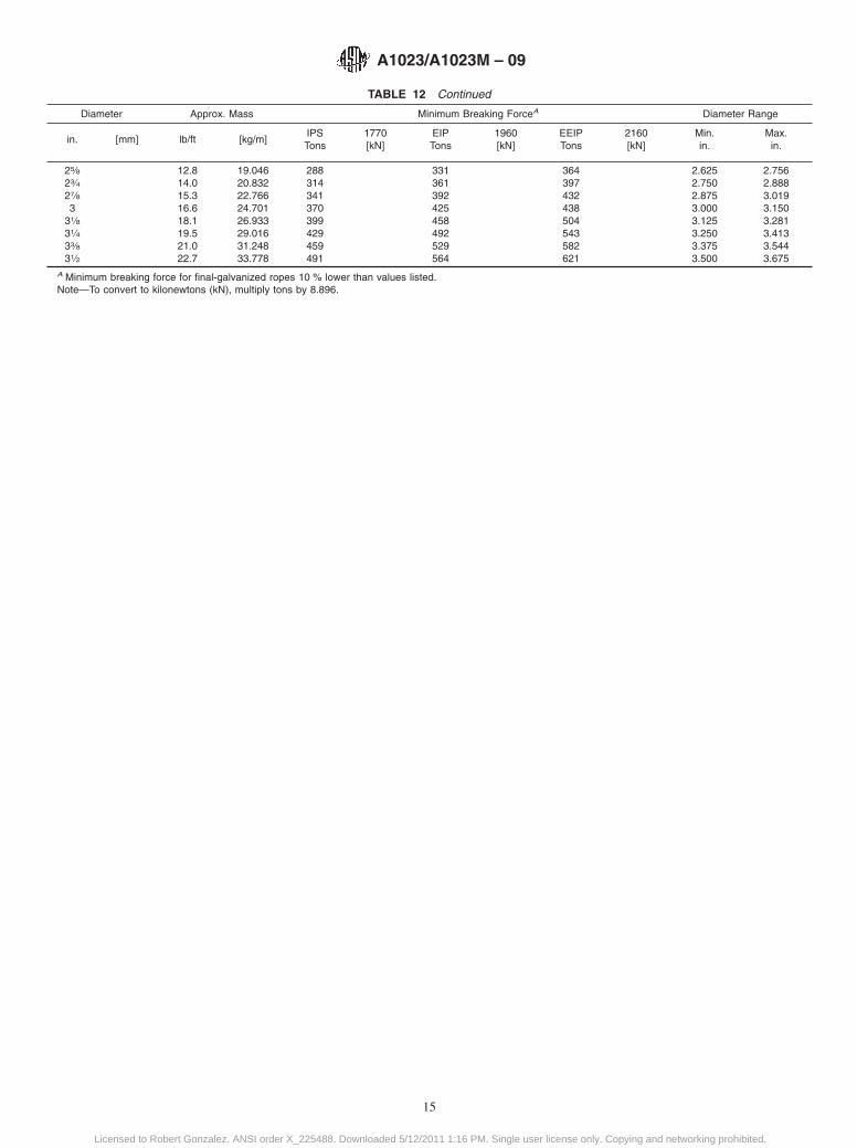
TABLE 12 Continued
Diameter Approx. Mass Minimum Breaking ForceA Diameter Range
in. [mm] lb/ft [kg/m]IPS 1770 EIP 1960 EEIP 2160 Min. Max.Tons [kN] Tons [kN] Tons [kN] in. in.
25⁄8 12.8 19.046 288 331 364 2.625 2.75623⁄4 14.0 20.832 314 361 397 2.750 2.88827⁄8 15.3 22.766 341 392 432 2.875 3.0193 16.6 24.701 370 425 438 3.000 3.150
31⁄8 18.1 26.933 399 458 504 3.125 3.28131⁄4 19.5 29.016 429 492 543 3.250 3.41333⁄8 21.0 31.248 459 529 582 3.375 3.54431⁄2 22.7 33.778 491 564 621 3.500 3.675
A Minimum breaking force for final-galvanized ropes 10 % lower than values listed.Note—To convert to kilonewtons (kN), multiply tons by 8.896.
A1023/A1023M – 09
15
Licensed to Robert Gonzalez. ANSI order X_225488. Downloaded 5/12/2011 1:16 PM. Single user license only. Copying and networking prohibited.
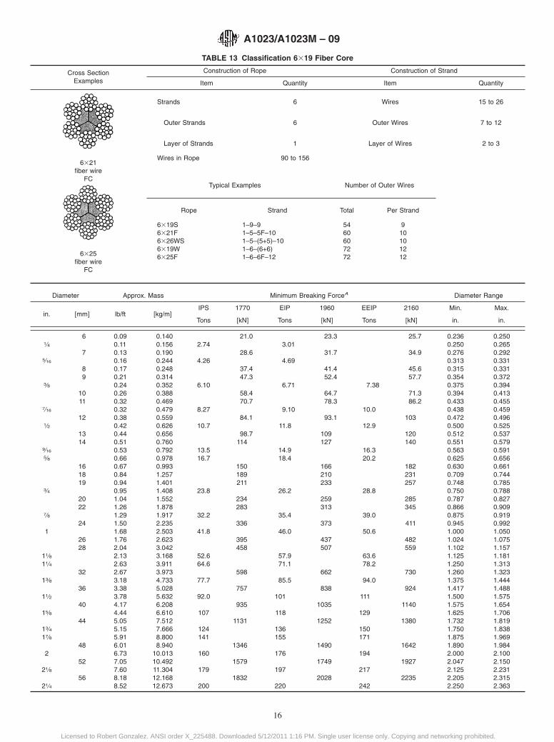
TABLE 13 Classification 6319 Fiber Core
Cross SectionExamples
Construction of Rope Construction of Strand
Item Quantity Item Quantity
6321fiber wire
FC
6325fiber wire
FC
Strands 6 Wires 15 to 26
Outer Strands 6 Outer Wires 7 to 12
Layer of Strands 1 Layer of Wires 2 to 3
Wires in Rope 90 to 156
Typical Examples Number of Outer Wires
Rope Strand Total Per Strand
6319S6321F6326WS6319W6325F
1–9–91–5–5F–101–5–(5+5)–101–6–(6+6)1–6–6F–12
5460607272
910101212
Diameter Approx. Mass Minimum Breaking ForceA Diameter Range
in. [mm] lb/ft [kg/m]IPS 1770 EIP 1960 EEIP 2160 Min. Max.
Tons [kN] Tons [kN] Tons [kN] in. in.
6 0.09 0.140 21.0 23.3 25.7 0.236 0.2501⁄4 0.11 0.156 2.74 3.01 0.250 0.265
7 0.13 0.190 28.6 31.7 34.9 0.276 0.2925⁄16 0.16 0.244 4.26 4.69 0.313 0.331
8 0.17 0.248 37.4 41.4 45.6 0.315 0.3319 0.21 0.314 47.3 52.4 57.7 0.354 0.372
3⁄8 0.24 0.352 6.10 6.71 7.38 0.375 0.39410 0.26 0.388 58.4 64.7 71.3 0.394 0.41311 0.32 0.469 70.7 78.3 86.2 0.433 0.455
7⁄16 0.32 0.479 8.27 9.10 10.0 0.438 0.45912 0.38 0.559 84.1 93.1 103 0.472 0.496
1⁄2 0.42 0.626 10.7 11.8 12.9 0.500 0.52513 0.44 0.656 98.7 109 120 0.512 0.53714 0.51 0.760 114 127 140 0.551 0.579
9⁄16 0.53 0.792 13.5 14.9 16.3 0.563 0.5915⁄8 0.66 0.978 16.7 18.4 20.2 0.625 0.656
16 0.67 0.993 150 166 182 0.630 0.66118 0.84 1.257 189 210 231 0.709 0.74419 0.94 1.401 211 233 257 0.748 0.785
3⁄4 0.95 1.408 23.8 26.2 28.8 0.750 0.78820 1.04 1.552 234 259 285 0.787 0.82722 1.26 1.878 283 313 345 0.866 0.909
7⁄8 1.29 1.917 32.2 35.4 39.0 0.875 0.91924 1.50 2.235 336 373 411 0.945 0.992
1 1.68 2.503 41.8 46.0 50.6 1.000 1.05026 1.76 2.623 395 437 482 1.024 1.07528 2.04 3.042 458 507 559 1.102 1.157
11⁄8 2.13 3.168 52.6 57.9 63.6 1.125 1.18111⁄4 2.63 3.911 64.6 71.1 78.2 1.250 1.313
32 2.67 3.973 598 662 730 1.260 1.32313⁄8 3.18 4.733 77.7 85.5 94.0 1.375 1.444
36 3.38 5.028 757 838 924 1.417 1.48811⁄2 3.78 5.632 92.0 101 111 1.500 1.575
40 4.17 6.208 935 1035 1140 1.575 1.65415⁄8 4.44 6.610 107 118 129 1.625 1.706
44 5.05 7.512 1131 1252 1380 1.732 1.81913⁄4 5.15 7.666 124 136 150 1.750 1.83817⁄8 5.91 8.800 141 155 171 1.875 1.969
48 6.01 8.940 1346 1490 1642 1.890 1.9842 6.73 10.013 160 176 194 2.000 2.100
52 7.05 10.492 1579 1749 1927 2.047 2.15021⁄8 7.60 11.304 179 197 217 2.125 2.231
56 8.18 12.168 1832 2028 2235 2.205 2.31521⁄4 8.52 12.673 200 220 242 2.250 2.363
A1023/A1023M – 09
16
Licensed to Robert Gonzalez. ANSI order X_225488. Downloaded 5/12/2011 1:16 PM. Single user license only. Copying and networking prohibited.

TABLE 13 Continued
Diameter Approx. Mass Minimum Breaking ForceA Diameter Range
in. [mm] lb/ft [kg/m]IPS 1770 EIP 1960 EEIP 2160 Min. Max.
Tons [kN] Tons [kN] Tons [kN] in. in.
60 9.39 13.968 2103 2328 2566 2.362 2.48023⁄8 9.49 14.120 222 244 269 2.375 2.49421⁄2 10.5 15.624 244 269 295 2.500 2.62525⁄8 11.6 17.261 268 294 324 2.625 2.75623⁄4 12.7 18.898 292 321 353 2.750 2.88827⁄8 13.9 20.683 317 349 384 2.875 3.0193 15.1 22.469 344 378 416 3.000 3.150
31⁄8 16.4 24.403 371 408 448 3.125 3.28131⁄4 17.7 26.338 399 438 483 3.250 3.41333⁄8 19.1 28.421 427 470 518 3.375 3.54431⁄2 20.6 30.653 457 503 552 3.500 3.675
A Minimum breaking force for final-galvanized ropes 10 % lower than values listed.Note—To convert to kilonewtons (kN), multiply tons by 8.896.
A1023/A1023M – 09
17
Licensed to Robert Gonzalez. ANSI order X_225488. Downloaded 5/12/2011 1:16 PM. Single user license only. Copying and networking prohibited.
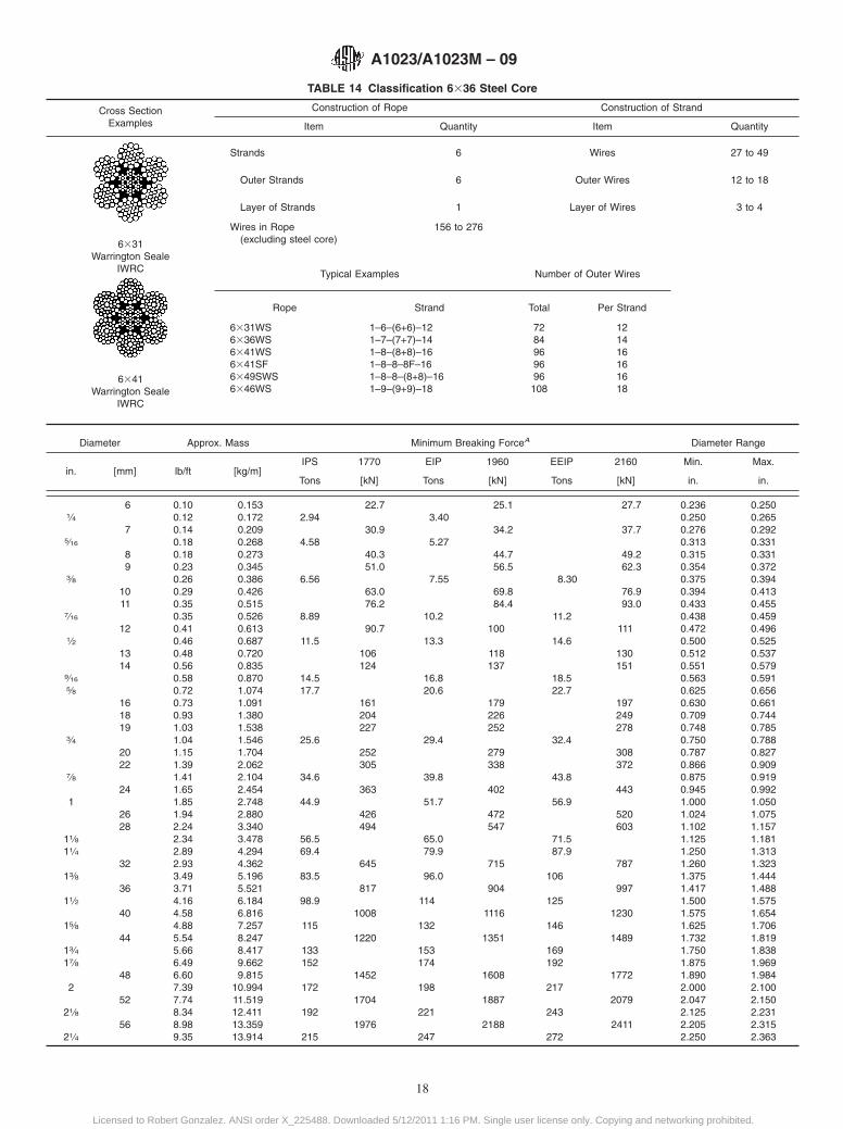
TABLE 14 Classification 6336 Steel Core
Cross SectionExamples
Construction of Rope Construction of Strand
Item Quantity Item Quantity
6331Warrington Seale
IWRC
6341Warrington Seale
IWRC
Strands 6 Wires 27 to 49
Outer Strands 6 Outer Wires 12 to 18
Layer of Strands 1 Layer of Wires 3 to 4
Wires in Rope(excluding steel core)
156 to 276
Typical Examples Number of Outer Wires
Rope Strand Total Per Strand
6331WS6336WS6341WS6341SF6349SWS6346WS
1–6–(6+6)–121–7–(7+7)–141–8–(8+8)–161–8–8–8F–161–8–8–(8+8)–161–9–(9+9)–18
7284969696108
121416161618
Diameter Approx. Mass Minimum Breaking ForceA Diameter Range
in. [mm] lb/ft [kg/m]IPS 1770 EIP 1960 EEIP 2160 Min. Max.
Tons [kN] Tons [kN] Tons [kN] in. in.
6 0.10 0.153 22.7 25.1 27.7 0.236 0.2501⁄4 0.12 0.172 2.94 3.40 0.250 0.265
7 0.14 0.209 30.9 34.2 37.7 0.276 0.2925⁄16 0.18 0.268 4.58 5.27 0.313 0.331
8 0.18 0.273 40.3 44.7 49.2 0.315 0.3319 0.23 0.345 51.0 56.5 62.3 0.354 0.372
3⁄8 0.26 0.386 6.56 7.55 8.30 0.375 0.39410 0.29 0.426 63.0 69.8 76.9 0.394 0.41311 0.35 0.515 76.2 84.4 93.0 0.433 0.455
7⁄16 0.35 0.526 8.89 10.2 11.2 0.438 0.45912 0.41 0.613 90.7 100 111 0.472 0.496
1⁄2 0.46 0.687 11.5 13.3 14.6 0.500 0.52513 0.48 0.720 106 118 130 0.512 0.53714 0.56 0.835 124 137 151 0.551 0.579
9⁄16 0.58 0.870 14.5 16.8 18.5 0.563 0.5915⁄8 0.72 1.074 17.7 20.6 22.7 0.625 0.656
16 0.73 1.091 161 179 197 0.630 0.66118 0.93 1.380 204 226 249 0.709 0.74419 1.03 1.538 227 252 278 0.748 0.785
3⁄4 1.04 1.546 25.6 29.4 32.4 0.750 0.78820 1.15 1.704 252 279 308 0.787 0.82722 1.39 2.062 305 338 372 0.866 0.909
7⁄8 1.41 2.104 34.6 39.8 43.8 0.875 0.91924 1.65 2.454 363 402 443 0.945 0.992
1 1.85 2.748 44.9 51.7 56.9 1.000 1.05026 1.94 2.880 426 472 520 1.024 1.07528 2.24 3.340 494 547 603 1.102 1.157
11⁄8 2.34 3.478 56.5 65.0 71.5 1.125 1.18111⁄4 2.89 4.294 69.4 79.9 87.9 1.250 1.313
32 2.93 4.362 645 715 787 1.260 1.32313⁄8 3.49 5.196 83.5 96.0 106 1.375 1.444
36 3.71 5.521 817 904 997 1.417 1.48811⁄2 4.16 6.184 98.9 114 125 1.500 1.575
40 4.58 6.816 1008 1116 1230 1.575 1.65415⁄8 4.88 7.257 115 132 146 1.625 1.706
44 5.54 8.247 1220 1351 1489 1.732 1.81913⁄4 5.66 8.417 133 153 169 1.750 1.83817⁄8 6.49 9.662 152 174 192 1.875 1.969
48 6.60 9.815 1452 1608 1772 1.890 1.9842 7.39 10.994 172 198 217 2.000 2.100
52 7.74 11.519 1704 1887 2079 2.047 2.15021⁄8 8.34 12.411 192 221 243 2.125 2.231
56 8.98 13.359 1976 2188 2411 2.205 2.31521⁄4 9.35 13.914 215 247 272 2.250 2.363
A1023/A1023M – 09
18
Licensed to Robert Gonzalez. ANSI order X_225488. Downloaded 5/12/2011 1:16 PM. Single user license only. Copying and networking prohibited.
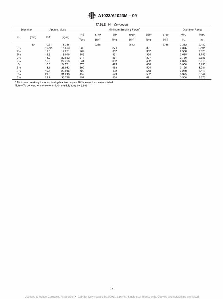
TABLE 14 Continued
Diameter Approx. Mass Minimum Breaking ForceA Diameter Range
in. [mm] lb/ft [kg/m]IPS 1770 EIP 1960 EEIP 2160 Min. Max.
Tons [kN] Tons [kN] Tons [kN] in. in.
60 10.31 15.336 2268 2512 2768 2.362 2.48023⁄8 10.42 15.503 239 274 301 2.375 2.49421⁄2 11.6 17.261 262 302 332 2.500 2.62525⁄8 12.8 19.046 288 331 364 2.625 2.75623⁄4 14.0 20.832 314 361 397 2.750 2.88827⁄8 15.3 22.766 341 392 432 2.875 3.0193 16.6 24.701 370 425 438 3.000 3.150
31⁄8 18.1 26.933 399 458 504 3.125 3.28131⁄4 19.5 29.016 429 492 543 3.250 3.41333⁄8 21.0 31.248 459 529 582 3.375 3.54431⁄2 22.7 33.778 491 564 621 3.500 3.675
A Minimum breaking force for final-galvanized ropes 10 % lower than values listed.Note—To convert to kilonewtons (kN), multiply tons by 8.896.
A1023/A1023M – 09
19
Licensed to Robert Gonzalez. ANSI order X_225488. Downloaded 5/12/2011 1:16 PM. Single user license only. Copying and networking prohibited.
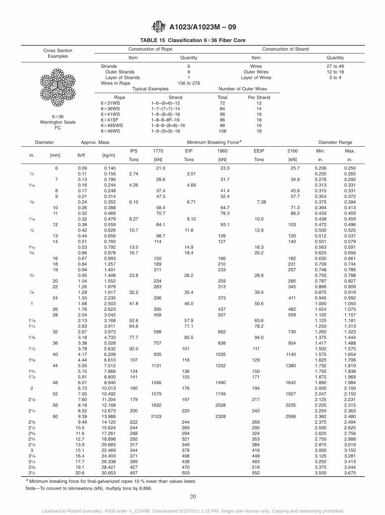
TABLE 15 Classification 6336 Fiber Core
Cross SectionExamples
Construction of Rope Construction of Strand
Item Quantity Item Quantity
6336Warrington Seale
FC
Strands 6 Wires 27 to 49Outer Strands 6 Outer Wires 12 to 18Layer of Strands 1 Layer of Wires 3 to 4
Wires in Rope 156 to 276Typical Examples Number of Outer Wires
Rope Strand Total Per Strand6331WS6336WS6341WS6341SF6349SWS6346WS
1–6–(6+6)–121–7–(7+7)–141–8–(8+8)–161–8–8–8F–161–8–8–(8+8)–161–9–(9+9)–18
7284969696108
121416161618
Diameter Approx. Mass Minimum Breaking ForceA Diameter Range
in. [mm] lb/ft [kg/m]IPS 1770 EIP 1960 EEIP 2160 Min. Max.
Tons [kN] Tons [kN] Tons [kN] in. in.
6 0.09 0.140 21.0 23.3 25.7 0.236 0.2501⁄4 0.11 0.156 2.74 3.01 0.250 0.265
7 0.13 0.190 28.6 31.7 34.9 0.276 0.2925⁄16 0.16 0.244 4.26 4.69 0.313 0.331
8 0.17 0.248 37.4 41.4 45.6 0.315 0.3319 0.21 0.314 47.3 52.4 57.7 0.354 0.372
3⁄8 0.24 0.352 6.10 6.71 7.38 0.375 0.39410 0.26 0.388 58.4 64.7 71.3 0.394 0.41311 0.32 0.469 70.7 78.3 86.2 0.433 0.455
7⁄16 0.32 0.479 8.27 9.10 10.0 0.438 0.45912 0.38 0.559 84.1 93.1 103 0.472 0.496
1⁄2 0.42 0.626 10.7 11.8 12.9 0.500 0.52513 0.44 0.656 98.7 109 120 0.512 0.53714 0.51 0.760 114 127 140 0.551 0.579
9⁄16 0.53 0.792 13.5 14.9 16.3 0.563 0.5915⁄8 0.66 0.978 16.7 18.4 20.2 0.625 0.656
16 0.67 0.993 150 166 182 0.630 0.66118 0.84 1.257 189 210 231 0.709 0.74419 0.94 1.401 211 233 257 0.748 0.785
3⁄4 0.95 1.408 23.8 26.2 28.8 0.750 0.78820 1.04 1.552 234 259 285 0.787 0.82722 1.26 1.878 283 313 345 0.866 0.909
7⁄8 1.29 1.917 32.2 35.4 39.0 0.875 0.91924 1.50 2.235 336 373 411 0.945 0.992
1 1.68 2.503 41.8 46.0 50.6 1.000 1.05026 1.76 2.623 395 437 482 1.024 1.07528 2.04 3.042 458 507 559 1.102 1.157
11⁄8 2.13 3.168 52.6 57.9 63.6 1.125 1.18111⁄4 2.63 3.911 64.6 71.1 78.2 1.250 1.313
32 2.67 3.973 598 662 730 1.260 1.32313⁄8 3.18 4.733 77.7 85.5 94.0 1.375 1.444
36 3.38 5.028 757 838 924 1.417 1.48811⁄2 3.78 5.632 92.0 101 111 1.500 1.575
40 4.17 6.208 935 1035 1140 1.575 1.65415⁄8 4.44 6.610 107 118 129 1.625 1.706
44 5.05 7.512 1131 1252 1380 1.732 1.81913⁄4 5.15 7.666 124 136 150 1.750 1.83817⁄8 5.91 8.800 141 155 171 1.875 1.969
48 6.01 8.940 1346 1490 1642 1.890 1.9842 6.73 10.013 160 176 194 2.000 2.100
52 7.05 10.492 1579 1749 1927 2.047 2.15021⁄8 7.60 11.304 179 197 217 2.125 2.231
56 8.18 12.168 1832 2028 2235 2.205 2.31521⁄4 8.52 12.673 200 220 242 2.250 2.363
60 9.39 13.968 2103 2328 2566 2.362 2.48023⁄8 9.49 14.120 222 244 269 2.375 2.49421⁄2 10.5 15.624 244 269 295 2.500 2.62525⁄8 11.6 17.261 268 294 324 2.625 2.75623⁄4 12.7 18.898 292 321 353 2.750 2.88827⁄8 13.9 20.683 317 349 384 2.875 3.0193 15.1 22.469 344 378 416 3.000 3.150
31⁄8 16.4 24.403 371 408 448 3.125 3.28131⁄4 17.7 26.338 399 438 483 3.250 3.41333⁄8 19.1 28.421 427 470 518 3.375 3.54431⁄2 20.6 30.653 457 503 552 3.500 3.675
A Minimum breaking force for final-galvanized ropes 10 % lower than values listed.
Note—To convert to kilonewtons (kN), multiply tons by 8.896.
A1023/A1023M – 09
20
Licensed to Robert Gonzalez. ANSI order X_225488. Downloaded 5/12/2011 1:16 PM. Single user license only. Copying and networking prohibited.
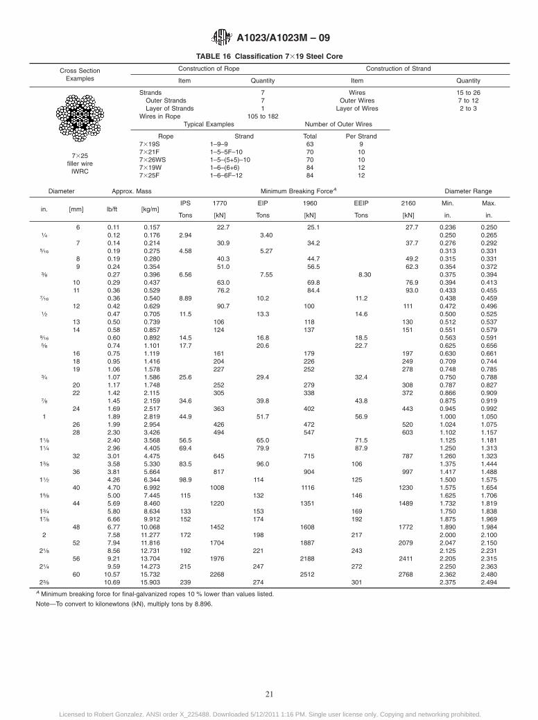
TABLE 16 Classification 7319 Steel Core
Cross SectionExamples
Construction of Rope Construction of Strand
Item Quantity Item Quantity
7325filler wire
IWRC
Strands 7 Wires 15 to 26Outer Strands 7 Outer Wires 7 to 12Layer of Strands 1 Layer of Wires 2 to 3
Wires in Rope 105 to 182Typical Examples Number of Outer Wires
Rope Strand Total Per Strand7319S7321F7326WS7319W7325F
1–9–91–5–5F–101–5–(5+5)–101–6–(6+6)1–6–6F–12
6370708484
910101212
Diameter Approx. Mass Minimum Breaking ForceA Diameter Range
in. [mm] lb/ft [kg/m]IPS 1770 EIP 1960 EEIP 2160 Min. Max.
Tons [kN] Tons [kN] Tons [kN] in. in.
6 0.11 0.157 22.7 25.1 27.7 0.236 0.2501⁄4 0.12 0.176 2.94 3.40 0.250 0.265
7 0.14 0.214 30.9 34.2 37.7 0.276 0.2925⁄16 0.19 0.275 4.58 5.27 0.313 0.331
8 0.19 0.280 40.3 44.7 49.2 0.315 0.3319 0.24 0.354 51.0 56.5 62.3 0.354 0.372
3⁄8 0.27 0.396 6.56 7.55 8.30 0.375 0.39410 0.29 0.437 63.0 69.8 76.9 0.394 0.41311 0.36 0.529 76.2 84.4 93.0 0.433 0.455
7⁄16 0.36 0.540 8.89 10.2 11.2 0.438 0.45912 0.42 0.629 90.7 100 111 0.472 0.496
1⁄2 0.47 0.705 11.5 13.3 14.6 0.500 0.52513 0.50 0.739 106 118 130 0.512 0.53714 0.58 0.857 124 137 151 0.551 0.579
9⁄16 0.60 0.892 14.5 16.8 18.5 0.563 0.5915⁄8 0.74 1.101 17.7 20.6 22.7 0.625 0.656
16 0.75 1.119 161 179 197 0.630 0.66118 0.95 1.416 204 226 249 0.709 0.74419 1.06 1.578 227 252 278 0.748 0.785
3⁄4 1.07 1.586 25.6 29.4 32.4 0.750 0.78820 1.17 1.748 252 279 308 0.787 0.82722 1.42 2.115 305 338 372 0.866 0.909
7⁄8 1.45 2.159 34.6 39.8 43.8 0.875 0.91924 1.69 2.517 363 402 443 0.945 0.992
1 1.89 2.819 44.9 51.7 56.9 1.000 1.05026 1.99 2.954 426 472 520 1.024 1.07528 2.30 3.426 494 547 603 1.102 1.157
11⁄8 2.40 3.568 56.5 65.0 71.5 1.125 1.18111⁄4 2.96 4.405 69.4 79.9 87.9 1.250 1.313
32 3.01 4.475 645 715 787 1.260 1.32313⁄8 3.58 5.330 83.5 96.0 106 1.375 1.444
36 3.81 5.664 817 904 997 1.417 1.48811⁄2 4.26 6.344 98.9 114 125 1.500 1.575
40 4.70 6.992 1008 1116 1230 1.575 1.65415⁄8 5.00 7.445 115 132 146 1.625 1.706
44 5.69 8.460 1220 1351 1489 1.732 1.81913⁄4 5.80 8.634 133 153 169 1.750 1.83817⁄8 6.66 9.912 152 174 192 1.875 1.969
48 6.77 10.068 1452 1608 1772 1.890 1.9842 7.58 11.277 172 198 217 2.000 2.100
52 7.94 11.816 1704 1887 2079 2.047 2.15021⁄8 8.56 12.731 192 221 243 2.125 2.231
56 9.21 13.704 1976 2188 2411 2.205 2.31521⁄4 9.59 14.273 215 247 272 2.250 2.363
60 10.57 15.732 2268 2512 2768 2.362 2.48023⁄8 10.69 15.903 239 274 301 2.375 2.494
A Minimum breaking force for final-galvanized ropes 10 % lower than values listed.
Note—To convert to kilonewtons (kN), multiply tons by 8.896.
A1023/A1023M – 09
21
Licensed to Robert Gonzalez. ANSI order X_225488. Downloaded 5/12/2011 1:16 PM. Single user license only. Copying and networking prohibited.
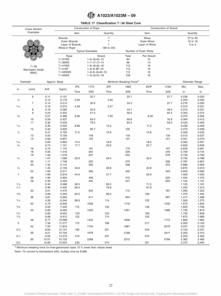
TABLE 17 Classification 7336 Steel Core
Cross SectionExamples
Construction of Rope Construction of Strand
Item Quantity Item Quantity
7336Warrington Seale
IWRC
Strands 7 Wires 27 to 49Outer Strands 7 Outer Wires 12 to 18Layer of Strands 1 Layer of Wires 3 to 4
Wires in Rope 189 to 343Typical Examples Number of Outer Wires
Rope Strand Total Per Strand7331WS7336WS7341WS7341SF7349SWS7346WS
1–6–(6+6)–121–7–(7+7)–141–8–(8+8)–161–8–8–8F–161–8–8–(8+8)–161–9–(9+9)–18
8498112112112126
121416161618
Diameter Approx. Mass Minimum Breaking ForceA Diameter Range
in. [mm] lb/ft [kg/m]IPS 1770 EIP 1960 EEIP 2160 Min. Max.
Tons [kN] Tons [kN] Tons [kN] in. in.
6 0.11 0.157 22.7 25.1 27.7 0.236 0.2501⁄4 0.12 0.176 2.94 3.40 0.250 0.265
7 0.14 0.214 30.9 34.2 37.7 0.276 0.2925⁄16 0.19 0.275 4.58 5.27 0.313 0.331
8 0.19 0.280 40.3 44.7 49.2 0.315 0.3319 0.24 0.354 51.0 56.5 62.3 0.354 0.372
3⁄8 0.27 0.396 6.56 7.55 8.30 0.375 0.39410 0.29 0.437 63.0 69.8 76.9 0.394 0.41311 0.36 0.529 76.2 84.4 93.0 0.433 0.455
7⁄16 0.36 0.540 8.89 10.2 11.2 0.438 0.45912 0.42 0.629 90.7 100 111 0.472 0.496
1⁄2 0.47 0.705 11.5 13.3 14.6 0.500 0.52513 0.50 0.739 106 118 130 0.512 0.53714 0.58 0.857 124 137 151 0.551 0.579
9⁄16 0.60 0.892 14.5 16.8 18.5 0.563 0.5915⁄8 0.74 1.101 17.7 20.6 22.7 0.625 0.656
16 0.75 1.119 161 179 197 0.630 0.66118 0.95 1.416 204 226 249 0.709 0.74419 1.06 1.578 227 252 278 0.748 0.785
3⁄4 1.07 1.586 25.6 29.4 32.4 0.750 0.78820 1.17 1.748 252 279 308 0.787 0.82722 1.42 2.115 305 338 372 0.866 0.909
7⁄8 1.45 2.159 34.6 39.8 43.8 0.875 0.91924 1.69 2.517 363 402 443 0.945 0.992
1 1.89 2.819 44.9 51.7 56.9 1.000 1.05026 1.99 2.954 426 472 520 1.024 1.07528 2.30 3.426 494 547 603 1.102 1.157
11⁄8 2.40 3.568 56.5 65.0 71.5 1.125 1.18111⁄4 2.96 4.405 69.4 79.9 87.9 1.250 1.313
32 3.01 4.475 645 715 787 1.260 1.32313⁄8 3.58 5.330 83.5 96.0 106 1.375 1.444
36 3.81 5.664 817 904 997 1.417 1.48811⁄2 4.26 6.344 98.9 114 125 1.500 1.575
40 4.70 6.992 1008 1116 1230 1.575 1.65415⁄8 5.00 7.445 115 132 146 1.625 1.706
44 5.69 8.460 1220 1351 1489 1.732 1.81913⁄4 5.80 8.634 133 153 169 1.750 1.83817⁄8 6.66 9.912 152 174 192 1.875 1.969
48 6.77 10.068 1452 1608 1772 1.890 1.9842 7.58 11.277 172 198 217 2.000 2.100
52 7.94 11.816 1704 1887 2079 2.047 2.15021⁄8 8.56 12.731 192 221 243 2.125 2.231
56 9.21 13.704 1976 2188 2411 2.205 2.31521⁄4 9.59 14.273 215 247 272 2.250 2.363
60 10.57 15.732 2268 2512 2768 2.362 2.48023⁄8 10.69 15.903 239 274 301 2.375 2.494
A Minimum breaking force for final-galvanized ropes 10 % lower than values listed.
Note—To convert to kilonewtons (kN), multiply tons by 8.896.
A1023/A1023M – 09
22
Licensed to Robert Gonzalez. ANSI order X_225488. Downloaded 5/12/2011 1:16 PM. Single user license only. Copying and networking prohibited.

TABLE 18 Classification 8319 Steel Core
Cross SectionExamples
Construction of Rope Construction of Strand
Item Quantity Item Quantity
8319 SealeIWRC
8325Filler Wire
IWRC
Strands 8 Wires 15 to 26
Outer Strands 8 Outer Wires 7 to 12
Layer of Strands 1 Layer of Wires 2 to 3
Wires in Rope(excluding steel core)
120 to 232
Typical Examples Number of Outer Wires
Rope Strand Total Per Strand
8319S8321F8326WS8319W8325F
1–9–91–5–5F–101–5–(5+5)–101–6–(6+6)1–6–6F–12
7280809696
910101212
Diameter Approx. Mass Minimum Breaking ForceA Diameter Range
in. [mm] lb/ft [kg/m]IPS 1770 EIP 1960 EEIP 2160 Min. Max.
Tons [kN] Tons [kN] Tons [kN] in. in.
6 0.11 0.161 22.7 25.1 27.7 0.236 0.2501⁄4 0.12 0.180 2.94 3.40 0.250 0.265
7 0.15 0.219 30.9 34.2 37.7 0.276 0.2925⁄16 0.19 0.281 4.58 5.27 0.313 0.331
8 0.19 0.285 40.3 44.7 49.2 0.315 0.3319 0.24 0.361 51.0 56.5 62.3 0.354 0.372
3⁄8 0.27 0.405 6.56 7.55 8.30 0.375 0.39410 0.30 0.446 63.0 69.8 76.9 0.394 0.41311 0.36 0.540 76.2 84.4 93.0 0.433 0.455
7⁄16 0.37 0.551 8.89 10.2 11.2 0.438 0.45912 0.43 0.642 90.7 100 111 0.472 0.496
1⁄2 0.48 0.719 11.5 13.3 14.6 0.500 0.52513 0.51 0.754 106 118 130 0.512 0.53714 0.59 0.874 124 137 151 0.551 0.579
9⁄16 0.61 0.910 14.5 16.8 18.5 0.563 0.5915⁄8 0.76 1.124 17.7 20.6 22.7 0.625 0.656
16 0.77 1.142 161 179 197 0.630 0.66118 0.97 1.445 204 226 249 0.709 0.74419 1.08 1.610 227 252 278 0.748 0.785
3⁄4 1.09 1.619 25.6 29.4 32.4 0.750 0.78820 1.20 1.784 252 279 308 0.787 0.82722 1.45 2.159 305 338 372 0.866 0.909
7⁄8 1.48 2.203 34.6 39.8 43.8 0.875 0.91924 1.73 2.569 363 402 443 0.945 0.992
1 1.93 2.877 44.9 51.7 56.9 1.000 1.05026 2.03 3.015 426 472 520 1.024 1.07528 2.35 3.497 494 547 603 1.102 1.157
11⁄8 2.45 3.642 56.5 65.0 71.5 1.125 1.18111⁄4 3.02 4.496 69.4 79.9 87.9 1.250 1.313
32 3.07 4.567 645 715 787 1.260 1.32313⁄8 3.66 5.440 83.5 96.0 106 1.375 1.444
36 3.88 5.780 817 904 997 1.417 1.48811⁄2 4.35 6.474 98.9 114 125 1.500 1.575
40 4.80 7.136 1008 1116 1230 1.575 1.65415⁄8 5.11 7.598 115 132 146 1.625 1.706
44 5.80 8.635 1220 1351 1489 1.732 1.81913⁄4 5.92 8.812 133 153 169 1.750 1.83817⁄8 6.80 10.116 152 174 192 1.875 1.969
48 6.91 10.276 1452 1608 1772 1.890 1.9842 7.73 11.510 172 198 217 2.000 2.100
52 8.10 12.060 1704 1887 2079 2.047 2.15021⁄8 8.73 12.993 192 221 243 2.125 2.231
56 9.40 13.987 1976 2188 2411 2.205 2.31521⁄4 9.79 14.567 215 247 272 2.250 2.363
60 10.79 16.056 2268 2512 2768 2.362 2.48023⁄8 10.91 16.230 239 274 301 2.375 2.494
A Minimum breaking force for final-galvanized ropes 10 % lower than values listed.
Note—To convert to kilonewtons (kN), multiply tons by 8.896.
A1023/A1023M – 09
23
Licensed to Robert Gonzalez. ANSI order X_225488. Downloaded 5/12/2011 1:16 PM. Single user license only. Copying and networking prohibited.
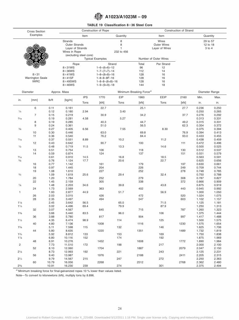
TABLE 19 Classification 8336 Steel Core
Cross SectionExamples
Construction of Rope Construction of Strand
Item Quantity Item Quantity
8331Warrington Seale
IWRC
Strands 8 Wires 29 to 57Outer Strands 8 Outer Wires 12 to 18Layer of Strands 1 Layer of Wires 3 to 4
Wires in Rope(excluding steel core)
232 to 456
Typical Examples Number of Outer Wires
Rope Strand Total Per Strand8331WS8336WS8341WS8341SF8349SWS8346WS
1–6–(6+6)–121–7–(7+7)–141–8–(8+8)–161–8–8–8F–161–8–8–(8+8)–161–9–(9+9)–18
96112128128128144
121416161618
Diameter Approx. Mass Minimum Breaking ForceA Diameter Range
in. [mm] lb/ft [kg/m]IPS 1770 EIP 1960 EEIP 2160 Min. Max.
Tons [kN] Tons [kN] Tons [kN] in. in.
6 0.11 0.161 22.7 25.1 27.7 0.236 0.2501⁄4 0.12 0.180 2.94 3.40 0.250 0.265
7 0.15 0.219 30.9 34.2 37.7 0.276 0.2925⁄16 0.19 0.281 4.58 5.27 0.313 0.331
8 0.19 0.285 40.3 44.7 49.2 0.315 0.3319 0.24 0.361 51.0 56.5 62.3 0.354 0.372
3⁄8 0.27 0.405 6.56 7.55 8.30 0.375 0.39410 0.30 0.446 63.0 69.8 76.9 0.394 0.41311 0.36 0.540 76.2 84.4 93.0 0.433 0.455
7⁄16 0.37 0.551 8.89 10.2 11.2 0.438 0.45912 0.43 0.642 90.7 100 111 0.472 0.496
1⁄2 0.48 0.719 11.5 13.3 14.6 0.500 0.52513 0.51 0.754 106 118 130 0.512 0.53714 0.59 0.874 124 137 151 0.551 0.579
9⁄16 0.61 0.910 14.5 16.8 18.5 0.563 0.5915⁄8 0.76 1.124 17.7 20.6 22.7 0.625 0.656
16 0.77 1.142 161 179 197 0.630 0.66118 0.97 1.445 204 226 249 0.709 0.74419 1.08 1.610 227 252 278 0.748 0.785
3⁄4 1.09 1.619 25.6 29.4 32.4 0.750 0.78820 1.20 1.784 252 279 308 0.787 0.82722 1.45 2.159 305 338 372 0.866 0.909
7⁄8 1.48 2.203 34.6 39.8 43.8 0.875 0.91924 1.73 2.569 363 402 443 0.945 0.992
1 1.93 2.877 44.9 51.7 56.9 1.000 1.05026 2.03 3.015 426 472 520 1.024 1.07528 2.35 3.497 494 547 603 1.102 1.157
11⁄8 2.45 3.642 56.5 65.0 71.5 1.125 1.18111⁄4 3.02 4.496 69.4 79.9 87.9 1.250 1.313
32 3.07 4.567 645 715 787 1.260 1.32313⁄8 3.66 5.440 83.5 96.0 106 1.375 1.444
36 3.88 5.780 817 904 997 1.417 1.48811⁄2 4.35 6.474 98.9 114 125 1.500 1.575
40 4.80 7.136 1008 1116 1230 1.575 1.65415⁄8 5.11 7.598 115 132 146 1.625 1.706
44 5.80 8.635 1220 1351 1489 1.732 1.81913⁄4 5.92 8.812 133 153 169 1.750 1.83817⁄8 6.80 10.116 152 174 192 1.875 1.969
48 6.91 10.276 1452 1608 1772 1.890 1.9842 7.73 11.510 172 198 217 2.000 2.100
52 8.10 12.060 1704 1887 2079 2.047 2.15021⁄8 8.73 12.993 192 221 243 2.125 2.231
56 9.40 13.987 1976 2188 2411 2.205 2.31521⁄4 9.79 14.567 215 247 272 2.250 2.363
60 10.79 16.056 2268 2512 2768 2.362 2.48023⁄8 10.91 16.230 239 274 301 2.375 2.494
A Minimum breaking force for final-galvanized ropes 10 % lower than values listed.
Note—To convert to kilonewtons (kN), multiply tons by 8.896.
A1023/A1023M – 09
24
Licensed to Robert Gonzalez. ANSI order X_225488. Downloaded 5/12/2011 1:16 PM. Single user license only. Copying and networking prohibited.
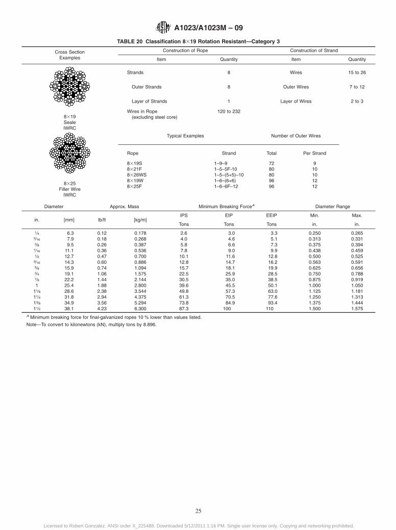
TABLE 20 Classification 8319 Rotation Resistant—Category 3
Cross SectionExamples
Construction of Rope Construction of Strand
Item Quantity Item Quantity
8319SealeIWRC
8325Filler Wire
IWRC
Strands 8 Wires 15 to 26
Outer Strands 8 Outer Wires 7 to 12
Layer of Strands 1 Layer of Wires 2 to 3
Wires in Rope(excluding steel core)
120 to 232
Typical Examples Number of Outer Wires
Rope Strand Total Per Strand
8319S8321F8326WS8319W8325F
1–9–91–5–5F-101–5–(5+5)–101–6–(6+6)1–6–6F–12
7280809696
910101212
Diameter Approx. Mass Minimum Breaking ForceA Diameter Range
in. [mm] lb/ft [kg/m]IPS EIP EEIP Min. Max.
Tons Tons Tons in. in.
1⁄4 6.3 0.12 0.178 2.6 3.0 3.3 0.250 0.2655⁄16 7.9 0.18 0.268 4.0 4.6 5.1 0.313 0.3313⁄8 9.5 0.26 0.387 5.8 6.6 7.3 0.375 0.3947⁄16 11.1 0.36 0.536 7.8 9.0 9.9 0.438 0.4591⁄2 12.7 0.47 0.700 10.1 11.6 12.8 0.500 0.5259⁄16 14.3 0.60 0.886 12.8 14.7 16.2 0.563 0.5915⁄8 15.9 0.74 1.094 15.7 18.1 19.9 0.625 0.6563⁄4 19.1 1.06 1.575 22.5 25.9 28.5 0.750 0.7887⁄8 22.2 1.44 2.144 30.5 35.0 38.5 0.875 0.9191 25.4 1.88 2.800 39.6 45.5 50.1 1.000 1.050
11⁄8 28.6 2.38 3.544 49.8 57.3 63.0 1.125 1.18111⁄4 31.8 2.94 4.375 61.3 70.5 77.6 1.250 1.31313⁄8 34.9 3.56 5.294 73.8 84.9 93.4 1.375 1.44411⁄2 38.1 4.23 6.300 87.3 100 110 1.500 1.575
A Minimum breaking force for final-galvanized ropes 10 % lower than values listed.
Note—To convert to kilonewtons (kN), multiply tons by 8.896.
A1023/A1023M – 09
25
Licensed to Robert Gonzalez. ANSI order X_225488. Downloaded 5/12/2011 1:16 PM. Single user license only. Copying and networking prohibited.
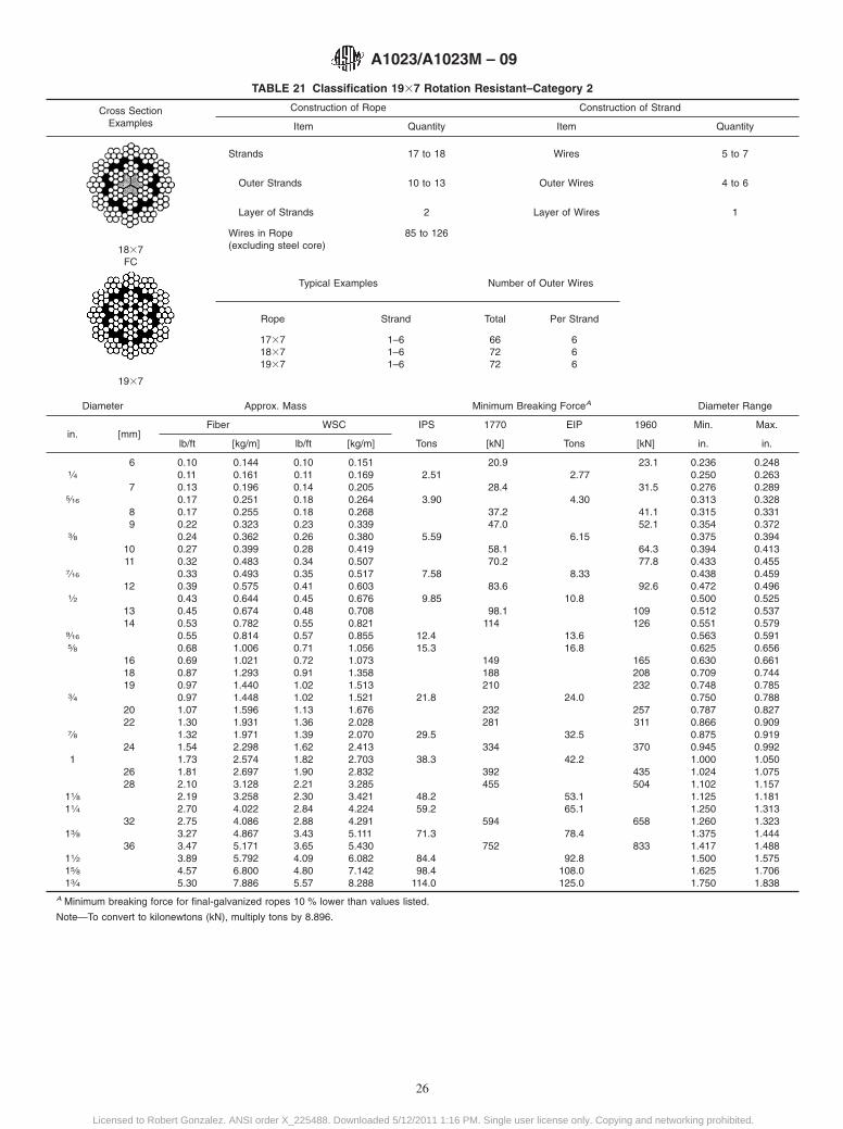
TABLE 21 Classification 1937 Rotation Resistant–Category 2
Cross SectionExamples
Construction of Rope Construction of Strand
Item Quantity Item Quantity
1837FC
1937
Strands 17 to 18 Wires 5 to 7
Outer Strands 10 to 13 Outer Wires 4 to 6
Layer of Strands 2 Layer of Wires 1
Wires in Rope(excluding steel core)
85 to 126
Typical Examples Number of Outer Wires
Rope Strand Total Per Strand
173718371937
1–61–61–6
667272
666
Diameter Approx. Mass Minimum Breaking ForceA Diameter Range
in. [mm]Fiber WSC IPS 1770 EIP 1960 Min. Max.
lb/ft [kg/m] lb/ft [kg/m] Tons [kN] Tons [kN] in. in.
6 0.10 0.144 0.10 0.151 20.9 23.1 0.236 0.2481⁄4 0.11 0.161 0.11 0.169 2.51 2.77 0.250 0.263
7 0.13 0.196 0.14 0.205 28.4 31.5 0.276 0.2895⁄16 0.17 0.251 0.18 0.264 3.90 4.30 0.313 0.328
8 0.17 0.255 0.18 0.268 37.2 41.1 0.315 0.3319 0.22 0.323 0.23 0.339 47.0 52.1 0.354 0.372
3⁄8 0.24 0.362 0.26 0.380 5.59 6.15 0.375 0.39410 0.27 0.399 0.28 0.419 58.1 64.3 0.394 0.41311 0.32 0.483 0.34 0.507 70.2 77.8 0.433 0.455
7⁄16 0.33 0.493 0.35 0.517 7.58 8.33 0.438 0.45912 0.39 0.575 0.41 0.603 83.6 92.6 0.472 0.496
1⁄2 0.43 0.644 0.45 0.676 9.85 10.8 0.500 0.52513 0.45 0.674 0.48 0.708 98.1 109 0.512 0.53714 0.53 0.782 0.55 0.821 114 126 0.551 0.579
9⁄16 0.55 0.814 0.57 0.855 12.4 13.6 0.563 0.5915⁄8 0.68 1.006 0.71 1.056 15.3 16.8 0.625 0.656
16 0.69 1.021 0.72 1.073 149 165 0.630 0.66118 0.87 1.293 0.91 1.358 188 208 0.709 0.74419 0.97 1.440 1.02 1.513 210 232 0.748 0.785
3⁄4 0.97 1.448 1.02 1.521 21.8 24.0 0.750 0.78820 1.07 1.596 1.13 1.676 232 257 0.787 0.82722 1.30 1.931 1.36 2.028 281 311 0.866 0.909
7⁄8 1.32 1.971 1.39 2.070 29.5 32.5 0.875 0.91924 1.54 2.298 1.62 2.413 334 370 0.945 0.992
1 1.73 2.574 1.82 2.703 38.3 42.2 1.000 1.05026 1.81 2.697 1.90 2.832 392 435 1.024 1.07528 2.10 3.128 2.21 3.285 455 504 1.102 1.157
11⁄8 2.19 3.258 2.30 3.421 48.2 53.1 1.125 1.18111⁄4 2.70 4.022 2.84 4.224 59.2 65.1 1.250 1.313
32 2.75 4.086 2.88 4.291 594 658 1.260 1.32313⁄8 3.27 4.867 3.43 5.111 71.3 78.4 1.375 1.444
36 3.47 5.171 3.65 5.430 752 833 1.417 1.48811⁄2 3.89 5.792 4.09 6.082 84.4 92.8 1.500 1.57515⁄8 4.57 6.800 4.80 7.142 98.4 108.0 1.625 1.70613⁄4 5.30 7.886 5.57 8.288 114.0 125.0 1.750 1.838
A Minimum breaking force for final-galvanized ropes 10 % lower than values listed.
Note—To convert to kilonewtons (kN), multiply tons by 8.896.
A1023/A1023M – 09
26
Licensed to Robert Gonzalez. ANSI order X_225488. Downloaded 5/12/2011 1:16 PM. Single user license only. Copying and networking prohibited.
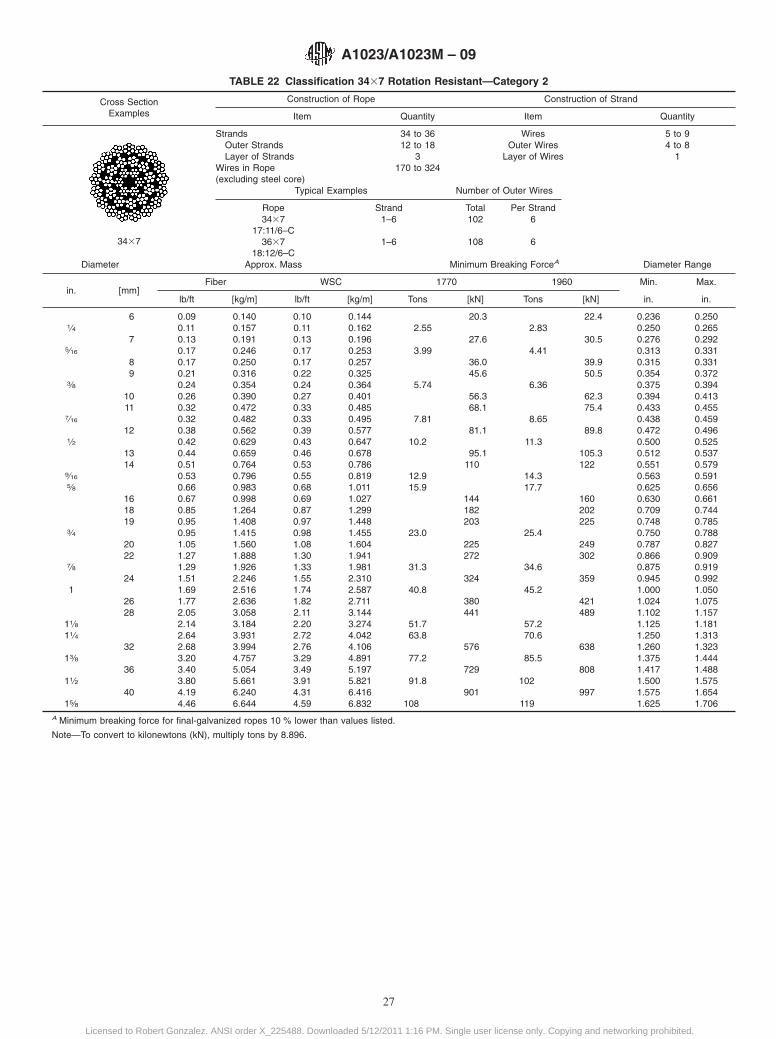
TABLE 22 Classification 3437 Rotation Resistant—Category 2
Cross SectionExamples
Construction of Rope Construction of Strand
Item Quantity Item Quantity
3437
Strands 34 to 36 Wires 5 to 9Outer Strands 12 to 18 Outer Wires 4 to 8Layer of Strands 3 Layer of Wires 1
Wires in Rope(excluding steel core)
170 to 324
Typical Examples Number of Outer Wires
Rope Strand Total Per Strand3437
17:11/6–C3637
18:12/6–C
1–6
1–6
102
108
6
6
Diameter Approx. Mass Minimum Breaking ForceA Diameter Range
in. [mm]Fiber WSC 1770 1960 Min. Max.
lb/ft [kg/m] lb/ft [kg/m] Tons [kN] Tons [kN] in. in.
6 0.09 0.140 0.10 0.144 20.3 22.4 0.236 0.2501⁄4 0.11 0.157 0.11 0.162 2.55 2.83 0.250 0.265
7 0.13 0.191 0.13 0.196 27.6 30.5 0.276 0.2925⁄16 0.17 0.246 0.17 0.253 3.99 4.41 0.313 0.331
8 0.17 0.250 0.17 0.257 36.0 39.9 0.315 0.3319 0.21 0.316 0.22 0.325 45.6 50.5 0.354 0.372
3⁄8 0.24 0.354 0.24 0.364 5.74 6.36 0.375 0.39410 0.26 0.390 0.27 0.401 56.3 62.3 0.394 0.41311 0.32 0.472 0.33 0.485 68.1 75.4 0.433 0.455
7⁄16 0.32 0.482 0.33 0.495 7.81 8.65 0.438 0.45912 0.38 0.562 0.39 0.577 81.1 89.8 0.472 0.496
1⁄2 0.42 0.629 0.43 0.647 10.2 11.3 0.500 0.52513 0.44 0.659 0.46 0.678 95.1 105.3 0.512 0.53714 0.51 0.764 0.53 0.786 110 122 0.551 0.579
9⁄16 0.53 0.796 0.55 0.819 12.9 14.3 0.563 0.5915⁄8 0.66 0.983 0.68 1.011 15.9 17.7 0.625 0.656
16 0.67 0.998 0.69 1.027 144 160 0.630 0.66118 0.85 1.264 0.87 1.299 182 202 0.709 0.74419 0.95 1.408 0.97 1.448 203 225 0.748 0.785
3⁄4 0.95 1.415 0.98 1.455 23.0 25.4 0.750 0.78820 1.05 1.560 1.08 1.604 225 249 0.787 0.82722 1.27 1.888 1.30 1.941 272 302 0.866 0.909
7⁄8 1.29 1.926 1.33 1.981 31.3 34.6 0.875 0.91924 1.51 2.246 1.55 2.310 324 359 0.945 0.992
1 1.69 2.516 1.74 2.587 40.8 45.2 1.000 1.05026 1.77 2.636 1.82 2.711 380 421 1.024 1.07528 2.05 3.058 2.11 3.144 441 489 1.102 1.157
11⁄8 2.14 3.184 2.20 3.274 51.7 57.2 1.125 1.18111⁄4 2.64 3.931 2.72 4.042 63.8 70.6 1.250 1.313
32 2.68 3.994 2.76 4.106 576 638 1.260 1.32313⁄8 3.20 4.757 3.29 4.891 77.2 85.5 1.375 1.444
36 3.40 5.054 3.49 5.197 729 808 1.417 1.48811⁄2 3.80 5.661 3.91 5.821 91.8 102 1.500 1.575
40 4.19 6.240 4.31 6.416 901 997 1.575 1.65415⁄8 4.46 6.644 4.59 6.832 108 119 1.625 1.706
A Minimum breaking force for final-galvanized ropes 10 % lower than values listed.
Note—To convert to kilonewtons (kN), multiply tons by 8.896.
A1023/A1023M – 09
27
Licensed to Robert Gonzalez. ANSI order X_225488. Downloaded 5/12/2011 1:16 PM. Single user license only. Copying and networking prohibited.
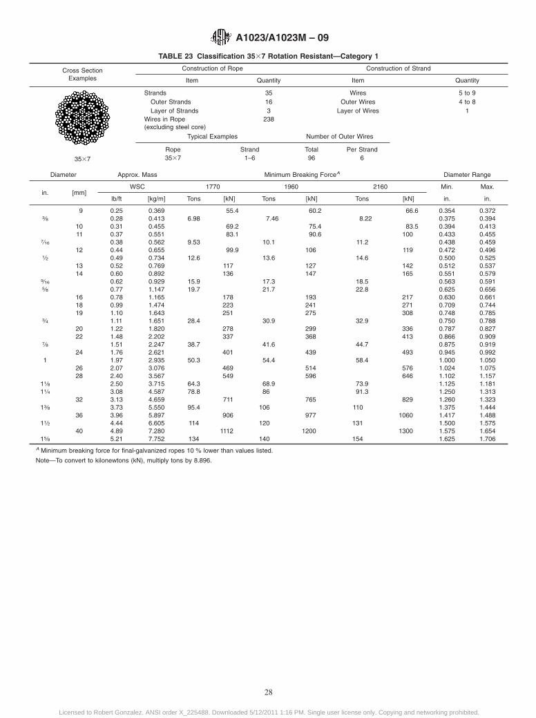
TABLE 23 Classification 3537 Rotation Resistant—Category 1
Cross SectionExamples
Construction of Rope Construction of Strand
Item Quantity Item Quantity
3537
Strands 35 Wires 5 to 9Outer Strands 16 Outer Wires 4 to 8Layer of Strands 3 Layer of Wires 1
Wires in Rope(excluding steel core)
238
Typical Examples Number of Outer Wires
Rope Strand Total Per Strand3537 1–6 96 6
Diameter Approx. Mass Minimum Breaking ForceA Diameter Range
in. [mm]WSC 1770 1960 2160 Min. Max.
lb/ft [kg/m] Tons [kN] Tons [kN] Tons [kN] in. in.
9 0.25 0.369 55.4 60.2 66.6 0.354 0.3723⁄8 0.28 0.413 6.98 7.46 8.22 0.375 0.394
10 0.31 0.455 69.2 75.4 83.5 0.394 0.41311 0.37 0.551 83.1 90.6 100 0.433 0.455
7⁄16 0.38 0.562 9.53 10.1 11.2 0.438 0.45912 0.44 0.655 99.9 106 119 0.472 0.496
1⁄2 0.49 0.734 12.6 13.6 14.6 0.500 0.52513 0.52 0.769 117 127 142 0.512 0.53714 0.60 0.892 136 147 165 0.551 0.579
9⁄16 0.62 0.929 15.9 17.3 18.5 0.563 0.5915⁄8 0.77 1.147 19.7 21.7 22.8 0.625 0.656
16 0.78 1.165 178 193 217 0.630 0.66118 0.99 1.474 223 241 271 0.709 0.74419 1.10 1.643 251 275 308 0.748 0.785
3⁄4 1.11 1.651 28.4 30.9 32.9 0.750 0.78820 1.22 1.820 278 299 336 0.787 0.82722 1.48 2.202 337 368 413 0.866 0.909
7⁄8 1.51 2.247 38.7 41.6 44.7 0.875 0.91924 1.76 2.621 401 439 493 0.945 0.992
1 1.97 2.935 50.3 54.4 58.4 1.000 1.05026 2.07 3.076 469 514 576 1.024 1.07528 2.40 3.567 549 596 646 1.102 1.157
11⁄8 2.50 3.715 64.3 68.9 73.9 1.125 1.18111⁄4 3.08 4.587 78.8 86 91.3 1.250 1.313
32 3.13 4.659 711 765 829 1.260 1.32313⁄8 3.73 5.550 95.4 106 110 1.375 1.444
36 3.96 5.897 906 977 1060 1.417 1.48811⁄2 4.44 6.605 114 120 131 1.500 1.575
40 4.89 7.280 1112 1200 1300 1.575 1.65415⁄8 5.21 7.752 134 140 154 1.625 1.706
A Minimum breaking force for final-galvanized ropes 10 % lower than values listed.
Note—To convert to kilonewtons (kN), multiply tons by 8.896.
A1023/A1023M – 09
28
Licensed to Robert Gonzalez. ANSI order X_225488. Downloaded 5/12/2011 1:16 PM. Single user license only. Copying and networking prohibited.

TABLE 24 Classification 6312 Fiber Core
Cross SectionExamples
Construction of Rope Construction of Strand
Item Quantity Item Quantity
6312Running Rope
FC
StrandsOuter StrandsLayer of Strands
Wires in Rope(excluding steel core)
66172
WiresOuter Wires
Layer of Wires
12121
Typical Examples Number of Outer Wires
Rope Strand Total per Strand
6312 FC-12 72 12
Diameter Approx. Mass Minimum Breaking Force Diameter Range
in. [mm] lb/ft [kg/m]IPS Min. Max.
Tons in. in.
5⁄16 7.9 0.10 0.152 2 0.313 0.3283⁄8 9.5 0.15 0.219 3.36 0.375 0.3947⁄16 11.1 0.20 0.298 4.55 0.438 0.4591⁄2 12.7 0.26 0.389 5.91 0.500 0.5259⁄16 14.3 0.33 0.492 7.45 0.563 0.5915⁄8 15.9 0.41 0.607 9.16 0.625 0.6563⁄4 19.1 0.59 0.875 13.1 0.750 0.788
13⁄16 20.6 0.69 1.026 15.3 0.813 0.8537⁄8 22.2 0.80 1.190 17.7 0.875 0.9191 25.4 1.04 1.555 23.0 1.000 1.050
Note—To convert to kilonewtons (kN), multiply tons by 8.896.
A1023/A1023M – 09
29
Licensed to Robert Gonzalez. ANSI order X_225488. Downloaded 5/12/2011 1:16 PM. Single user license only. Copying and networking prohibited.
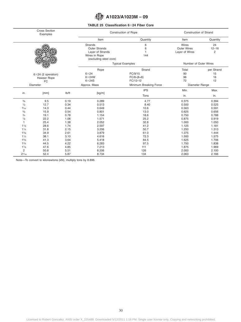
TABLE 25 Classification 6324 Fiber Core
Cross SectionExamples
Construction of Rope Construction of Strand
Item Quantity Item Quantity
6324 (2 operation)Hawser Rope
FC
StrandsOuter StrandsLayer of Strands
Wires in Rope(excluding steel core)
661
144
WiresOuter Wires
Layer of Wires
2412–16
2
Typical Examples Number of Outer Wires
Rope Strand Total per Strand63246324W6324S
FC/9/15FC/8-(8+8)FC/12-12
909672
151612
Diameter Approx. Mass Minimum Breaking Force Diameter Range
in. [mm] lb/ft [kg/m]IPS Min. Max.
Tons in. in.
3⁄8 9.5 0.19 0.289 4.77 0.375 0.3941⁄2 12.7 0.34 0.513 8.40 0.500 0.5259⁄16 14.3 0.44 0.649 10.6 0.563 0.5915⁄8 15.9 0.54 0.801 13.0 0.625 0.6563⁄4 19.1 0.78 1.154 18.6 0.750 0.7887⁄8 22.2 1.06 1.571 25.2 0.875 0.9191 25.4 1.38 2.052 32.8 1.000 1.050
11⁄8 28.6 1.74 2.597 41.2 1.125 1.18111⁄4 31.8 2.15 3.206 50.7 1.250 1.31313⁄8 34.9 2.61 3.879 61.0 1.375 1.44411⁄2 38.1 3.10 4.616 72.3 1.500 1.57515⁄8 41.3 3.64 5.418 84.5 1.625 1.70613⁄4 44.5 4.22 6.283 97.5 1.750 1.83817⁄8 47.6 4.85 7.213 111 1.875 1.9692 50.8 5.51 8.206 126 2.000 2.100
21⁄16 52.4 5.87 8.734 134 2.063 2.166
Note—To convert to kilonewtons (kN), multiply tons by 8.896.
A1023/A1023M – 09
30
Licensed to Robert Gonzalez. ANSI order X_225488. Downloaded 5/12/2011 1:16 PM. Single user license only. Copying and networking prohibited.
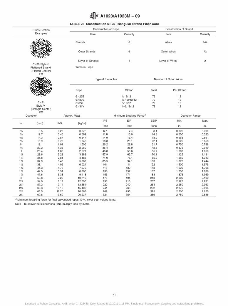
TABLE 26 Classification 6325 Triangular Strand Fiber Core
Cross SectionExamples
Construction of Rope Construction of Strand
Item Quantity Item Quantity
6330 Style GFlattened Strand(Plaited Center)
FC
6331Style V
(Brangle Center)FC
Strands 6 Wires 144
Outer Strands 6 Outer Wires 72
Layer of Strands 1 Layer of Wires 2
Wires in Rope
Typical Examples Number of Outer Wires
Rope Strand Total Per Strand
6325B6330G6327H6331V
1/12/12(332)/12/123/12/121–6/12/12
72727272
12121212
Diameter Approx. Mass Minimum Breaking ForceA Diameter Range
in. [mm] lb/ft [kg/m]IPS EIP EEIP Min. Max.
Tons Tons Tons in. in.
3⁄8 9.5 0.25 0.372 6.7 7.4 8.1 0.325 0.3941⁄2 12.7 0.45 0.669 11.8 13.0 14.3 0.500 0.5259⁄16 14.3 0.57 0.847 14.9 16.4 18.0 0.563 0.5915⁄8 15.9 0.70 1.046 18.3 20.1 22.1 0.625 0.6563⁄4 19.1 1.01 1.506 26.2 28.8 31.7 0.750 0.7887⁄8 22.2 1.38 2.050 35.4 38.9 42.8 0.875 0.9191 25.4 1.80 2.677 46.0 50.6 55.7 1.000 1.050
11⁄8 28.6 2.28 3.389 57.9 63.7 70.1 1.125 1.18111⁄4 31.8 2.81 4.183 71.0 78.1 85.9 1.250 1.31313⁄8 34.9 3.40 5.062 85.5 94.1 103 1.375 1.44411⁄2 38.1 4.05 6.024 101 111 122 1.500 1.57515⁄8 41.3 4.75 7.070 118 130 143 1.625 1.70613⁄4 44.5 5.51 8.200 138 152 167 1.750 1.83817⁄8 47.6 6.33 9.413 155 171 188 1.875 1.9692 50.8 7.20 10.710 176 194 213 2.000 2.100
21⁄8 54.0 8.12 12.090 196 215 237 2.125 2.23121⁄4 57.2 9.11 13.554 220 240 264 2.250 2.36323⁄8 60.3 10.15 15.102 241 265 292 2.375 2.49421⁄2 63.5 11.20 16.665 269 295 325 2.500 2.62523⁄4 69.8 13.60 20.237 321 354 389 2.750 2.888
A Minimum breaking force for final-galvanized ropes 10 % lower than values listed.
Note—To convert to kilonewtons (kN), multiply tons by 8.896.
A1023/A1023M – 09
31
Licensed to Robert Gonzalez. ANSI order X_225488. Downloaded 5/12/2011 1:16 PM. Single user license only. Copying and networking prohibited.
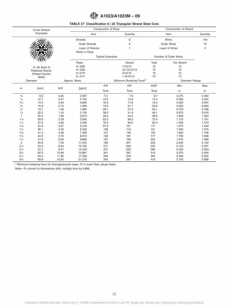
TABLE 27 Classification 6325 Triangular Strand Steel Core
Cross SectionExamples
Construction of Rope Construction of Strand
Item Quantity Item Quantity
6330 Style GFlattened Strand(Plated Center)
IWRC
Strands 6 Wires 144
Outer Strands 6 Outer Wires 72
Layer of Strands 1 Layer of Wires 2Wires in Rope
Typical Examples Number of Outer Wires
Rope Strand Total Per Strand6325B6330G6327H6331V
1/12/12(332)/12/123/12/121–6/12/12
72727272
12121212
Diameter Approx. Mass Minimum Breaking ForceA Diameter Range
in. [mm] lb/ft [kg/m]IPS EIP EEIP Min. Max.
Tons Tons Tons in. in.
3⁄8 9.5 0.26 0.387 7.2 7.9 8.7 0.375 0.3941⁄2 12.7 0.47 0.703 12.6 14.0 15.4 0.500 0.5259⁄16 14.3 0.60 0.890 16.0 17.6 19.4 0.563 0.5915⁄8 15.9 0.74 1.099 19.6 21.7 23.9 0.625 0.6563⁄4 19.1 1.06 1.582 28.1 31.0 34.1 0.750 0.7887⁄8 22.2 1.45 2.154 38.0 41.9 46.1 0.875 0.9191 25.4 1.89 2.813 49.4 54.4 59.8 1.000 1.050
11⁄8 28.6 2.39 3.560 62.2 68.5 75.4 1.125 1.18111⁄4 31.8 2.95 4.395 76.3 84.0 92.4 1.250 1.31313⁄8 34.9 3.57 5.318 91.9 101 111 1.375 1.44411⁄2 38.1 4.25 6.329 108 119 131 1.500 1.57515⁄8 41.3 4.99 7.428 127 140 154 1.625 1.70613⁄4 44.5 5.79 8.615 146 161 177 1.750 1.83817⁄8 47.6 6.65 9.889 167 184 202 1.875 1.9692 50.8 7.56 11.252 189 207 228 2.000 2.100
21⁄8 54.0 8.54 12.702 211 232 255 2.125 2.23121⁄4 57.2 9.57 14.240 237 260 286 2.250 2.36323⁄8 60.3 10.66 15.867 261 287 316 2.375 2.49421⁄2 63.5 11.80 17.558 289 318 350 2.500 2.62523⁄4 69.8 14.30 21.278 345 381 418 2.750 2.888
A Minimum breaking force for final-galvanized ropes 10 % lower than values listed.
Note—To convert to kilonewtons (kN), multiply tons by 8.896.
A1023/A1023M – 09
32
Licensed to Robert Gonzalez. ANSI order X_225488. Downloaded 5/12/2011 1:16 PM. Single user license only. Copying and networking prohibited.
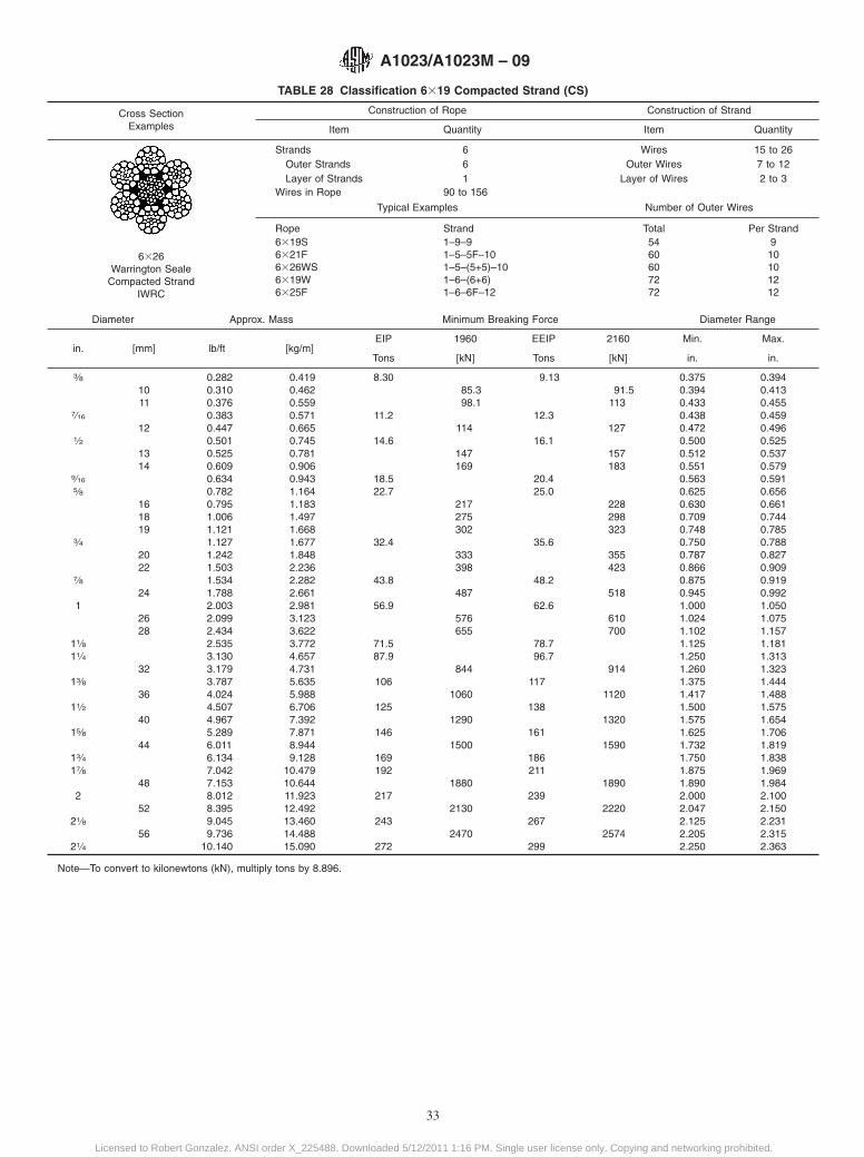
TABLE 28 Classification 6319 Compacted Strand (CS)
Cross SectionExamples
Construction of Rope Construction of Strand
Item Quantity Item Quantity
6326Warrington Seale
Compacted StrandIWRC
Strands 6 Wires 15 to 26Outer Strands 6 Outer Wires 7 to 12Layer of Strands 1 Layer of Wires 2 to 3
Wires in Rope 90 to 156
Typical Examples Number of Outer Wires
Rope Strand Total Per Strand6319S6321F6326WS6319W6325F
1–9–91–5–5F–101–5–(5+5)–101–6–(6+6)1–6–6F–12
5460607272
910101212
Diameter Approx. Mass Minimum Breaking Force Diameter Range
in. [mm] lb/ft [kg/m]EIP 1960 EEIP 2160 Min. Max.
Tons [kN] Tons [kN] in. in.
3⁄8 0.282 0.419 8.30 9.13 0.375 0.39410 0.310 0.462 85.3 91.5 0.394 0.41311 0.376 0.559 98.1 113 0.433 0.455
7⁄16 0.383 0.571 11.2 12.3 0.438 0.45912 0.447 0.665 114 127 0.472 0.496
1⁄2 0.501 0.745 14.6 16.1 0.500 0.52513 0.525 0.781 147 157 0.512 0.53714 0.609 0.906 169 183 0.551 0.579
9⁄16 0.634 0.943 18.5 20.4 0.563 0.5915⁄8 0.782 1.164 22.7 25.0 0.625 0.656
16 0.795 1.183 217 228 0.630 0.66118 1.006 1.497 275 298 0.709 0.74419 1.121 1.668 302 323 0.748 0.785
3⁄4 1.127 1.677 32.4 35.6 0.750 0.78820 1.242 1.848 333 355 0.787 0.82722 1.503 2.236 398 423 0.866 0.909
7⁄8 1.534 2.282 43.8 48.2 0.875 0.91924 1.788 2.661 487 518 0.945 0.992
1 2.003 2.981 56.9 62.6 1.000 1.05026 2.099 3.123 576 610 1.024 1.07528 2.434 3.622 655 700 1.102 1.157
11⁄8 2.535 3.772 71.5 78.7 1.125 1.18111⁄4 3.130 4.657 87.9 96.7 1.250 1.313
32 3.179 4.731 844 914 1.260 1.32313⁄8 3.787 5.635 106 117 1.375 1.444
36 4.024 5.988 1060 1120 1.417 1.48811⁄2 4.507 6.706 125 138 1.500 1.575
40 4.967 7.392 1290 1320 1.575 1.65415⁄8 5.289 7.871 146 161 1.625 1.706
44 6.011 8.944 1500 1590 1.732 1.81913⁄4 6.134 9.128 169 186 1.750 1.83817⁄8 7.042 10.479 192 211 1.875 1.969
48 7.153 10.644 1880 1890 1.890 1.9842 8.012 11.923 217 239 2.000 2.100
52 8.395 12.492 2130 2220 2.047 2.15021⁄8 9.045 13.460 243 267 2.125 2.231
56 9.736 14.488 2470 2574 2.205 2.31521⁄4 10.140 15.090 272 299 2.250 2.363
Note—To convert to kilonewtons (kN), multiply tons by 8.896.
A1023/A1023M – 09
33
Licensed to Robert Gonzalez. ANSI order X_225488. Downloaded 5/12/2011 1:16 PM. Single user license only. Copying and networking prohibited.

TABLE 29 Classification 6336 Compacted Strand (CS)
Cross SectionExamples
Construction of Rope Construction of Strand
Item Quantity Item Quantity
6336Compacted Strand
Strands 6 Wires 27 to 49Outer Strands 6 Outer Wires 12 to 18Layer of Strands 1 Layer of Wires 27 to 49
Wires in Rope 156 to 276Typical Examples Number of Outer Wires
Rope Strand Total Per Strand6331WS6336WS6341WS6341SF6349SWS6346WS
1–6–(6+6)–121–7–(7+7)–141–8–(8+8)–161–8–8–8F–161–8–8–(8+8)–161–9–(9+9)–18
7284969696108
121416161618
Diameter Approx. Mass Minimum Breaking Force Diameter Range
in. [mm] lb/ft [kg/m]EIP 1960 EEIP 2160 Min. Max.
Tons [kN] Tons [kN] in. in.
3⁄8 0.282 0.419 8.30 9.13 0.375 0.39410 0.310 0.462 85.3 91.5 0.394 0.41311 0.376 0.559 98.1 113 0.433 0.455
7⁄16 0.383 0.571 11.2 12.3 0.438 0.45912 0.447 0.665 114 127 0.472 0.496
1⁄2 0.501 0.745 14.6 16.1 0.500 0.52513 0.525 0.781 147 157 0.512 0.53714 0.609 0.906 169 183 0.551 0.579
9⁄16 0.634 0.943 18.5 20.4 0.563 0.5915⁄8 0.782 1.164 22.7 25.0 0.625 0.656
16 0.795 1.183 217 228 0.630 0.66118 1.006 1.497 275 298 0.709 0.74419 1.121 1.668 302 323 0.748 0.785
3⁄4 1.127 1.677 32.4 35.6 0.750 0.78820 1.242 1.848 333 355 0.787 0.82722 1.503 2.236 398 423 0.866 0.909
7⁄8 1.534 2.282 43.8 48.2 0.875 0.91924 1.788 2.661 487 518 0.945 0.992
1 2.003 2.981 56.9 62.6 1.000 1.05026 2.099 3.123 576 610 1.024 1.07528 2.434 3.622 655 700 1.102 1.157
11⁄8 2.535 3.772 71.5 78.7 1.125 1.18111⁄4 3.130 4.657 87.9 96.7 1.250 1.313
32 3.179 4.731 844 914 1.260 1.32313⁄8 3.787 5.635 106 117 1.375 1.444
36 4.024 5.988 1060 1120 1.417 1.48811⁄2 4.507 6.706 125 138 1.500 1.575
40 4.967 7.392 1290 1320 1.575 1.65415⁄8 5.289 7.871 146 161 1.625 1.706
44 6.011 8.944 1500 1590 1.732 1.81913⁄4 6.134 9.128 169 186 1.750 1.83817⁄8 7.042 10.479 192 211 1.875 1.969
48 7.153 10.644 1880 1890 1.890 1.9842 8.012 11.923 217 239 2.000 2.100
52 8.395 12.492 2130 2220 2.047 2.15021⁄8 9.045 13.460 243 267 2.125 2.231
56 9.736 14.488 2470 2574 2.205 2.31521⁄4 10.140 15.090 272 299 2.250 2.363
Note—To convert to kilonewtons (kN), multiply tons by 8.896.
A1023/A1023M – 09
34
Licensed to Robert Gonzalez. ANSI order X_225488. Downloaded 5/12/2011 1:16 PM. Single user license only. Copying and networking prohibited.

TABLE 30 Classification 6319 Swaged Rope (SW)
Cross SectionExamples
Construction of Rope Construction of Strand
Item Quantity Item Quantity
6326 WarringtonCompacted (Swaged)
IWRC
StrandsOuter StrandsLayer of Strands
Wires in Rope(excluding steel core)
661
90–156
WiresOuter Wires
Layer of Wires
15–267–122–3
Typical Examples Number of Outer Wires
Rope Strand Total per Strand6319S6321F6326WS6319W6325F
1–9–91–5–5F–101–5–(5+5)–101–6–(6+6)1–6–6F–12
5460607272
910101212
Diameter Approx. Mass Minimum Breaking Force Diameter Range
in. [mm] lb/ft [kg/m]EIP Min. Max.
Tons in. in.
1⁄2 12.7 0.55 0.826 15.5 0.500 0.5259⁄16 14.3 0.70 1.045 19.6 0.563 0.5915⁄8 15.9 0.87 1.290 24.2 0.625 0.6563⁄4 19.1 1.25 1.858 34.9 0.750 0.7887⁄8 22.2 1.70 2.529 47.4 0.875 0.9191 25.4 2.22 3.303 62.0 1.000 1.050
11⁄8 28.6 2.81 4.181 73.5 1.125 1.18111⁄4 31.8 3.47 5.161 90.0 1.250 1.31313⁄8 34.9 4.20 6.245 106 1.375 1.44411⁄2 38.1 4.99 7.432 130 1.500 1.575
Note—To convert to kilonewtons (kN), multiply tons by 8.896.Note—Also called compacted rope.
A1023/A1023M – 09
35
Licensed to Robert Gonzalez. ANSI order X_225488. Downloaded 5/12/2011 1:16 PM. Single user license only. Copying and networking prohibited.
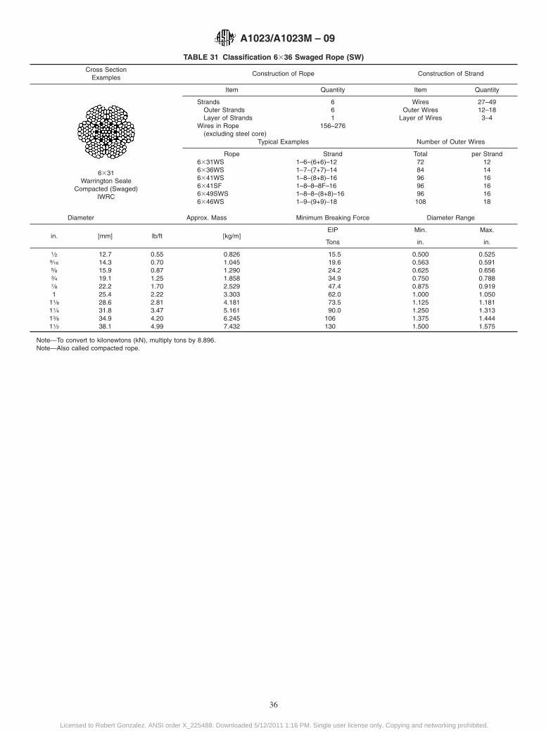
TABLE 31 Classification 6336 Swaged Rope (SW)
Cross SectionExamples
Construction of Rope Construction of Strand
Item Quantity Item Quantity
6331Warrington Seale
Compacted (Swaged)IWRC
StrandsOuter StrandsLayer of Strands
Wires in Rope(excluding steel core)
661
156–276
WiresOuter Wires
Layer of Wires
27–4912–183–4
Typical Examples Number of Outer Wires
Rope Strand Total per Strand6331WS6336WS6341WS6341SF6349SWS6346WS
1–6–(6+6)–121–7–(7+7)–141–8–(8+8)–161–8–8–8F–161–8–8–(8+8)–161–9–(9+9)–18
7284969696108
121416161618
Diameter Approx. Mass Minimum Breaking Force Diameter Range
in. [mm] lb/ft [kg/m]EIP Min. Max.
Tons in. in.
1⁄2 12.7 0.55 0.826 15.5 0.500 0.5259⁄16 14.3 0.70 1.045 19.6 0.563 0.5915⁄8 15.9 0.87 1.290 24.2 0.625 0.6563⁄4 19.1 1.25 1.858 34.9 0.750 0.7887⁄8 22.2 1.70 2.529 47.4 0.875 0.9191 25.4 2.22 3.303 62.0 1.000 1.050
11⁄8 28.6 2.81 4.181 73.5 1.125 1.18111⁄4 31.8 3.47 5.161 90.0 1.250 1.31313⁄8 34.9 4.20 6.245 106 1.375 1.44411⁄2 38.1 4.99 7.432 130 1.500 1.575
Note—To convert to kilonewtons (kN), multiply tons by 8.896.Note—Also called compacted rope.
A1023/A1023M – 09
36
Licensed to Robert Gonzalez. ANSI order X_225488. Downloaded 5/12/2011 1:16 PM. Single user license only. Copying and networking prohibited.
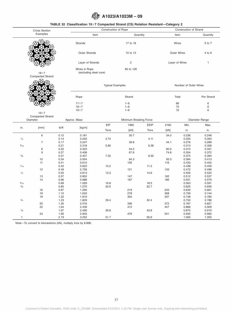
TABLE 32 Classification 1937 Compacted Strand (CS) Rotation Resistant—Category 2
Cross SectionExamples
Construction of Rope Construction of Strand
Item Quantity Item Quantity
1837Compacted Strand
1937Compacted Strand
Strands 17 to 18 Wires 5 to 7
Outer Strands 10 to 13 Outer Wires 4 to 6
Layer of Strands 2 Layer of Wires 1
Wires in Rope(excluding steel core)
85 to 126
Typical Examples Number of Outer Wires
Rope Strand Total Per Strand
173718371937
1–61–61–6
667272
666
Diameter Approx. Mass Minimum Breaking Force Diameter Range
in. [mm] lb/ft [kg/m]EIP 1960 EEIP 2160 Min. Max.
Tons [kN] Tons [kN] in. in.
6 0.12 0.181 30.7 34.0 0.236 0.2481⁄4 0.14 0.203 3.74 4.11 0.250 0.263
7 0.17 0.247 39.8 44.1 0.276 0.2895⁄16 0.21 0.318 5.80 6.38 0.313 0.328
8 0.22 0.323 54.2 60.0 0.315 0.3319 0.27 0.408 67.6 74.8 0.354 0.372
3⁄8 0.31 0.457 7.55 8.30 0.375 0.39410 0.34 0.504 84.3 93.3 0.394 0.41311 0.41 0.610 105 116 0.433 0.455
7⁄16 0.42 0.622 10.2 11.2 0.438 0.45912 0.49 0.726 121 133 0.472 0.496
1⁄2 0.55 0.813 13.3 14.6 0.500 0.52513 0.57 0.852 147 162 0.512 0.53714 0.66 0.988 167 185 0.551 0.579
9⁄16 0.69 1.029 16.8 18.5 0.563 0.5915⁄8 0.85 1.270 20.6 22.7 0.625 0.656
16 0.87 1.290 219 243 0.630 0.66118 1.10 1.633 278 308 0.709 0.74419 1.22 1.819 304 337 0.748 0.785
3⁄4 1.23 1.829 29.4 32.4 0.750 0.78820 1.35 2.016 336 372 0.787 0.82722 1.64 2.439 412 457 0.866 0.909
7⁄8 1.67 2.490 39.8 43.8 0.875 0.91924 1.95 2.903 476 541 0.945 0.992
1 2.19 3.252 51.7 56.9 1.000 1.050
Note—To convert to kilonewtons (kN), multiply tons by 8.896.
A1023/A1023M – 09
37
Licensed to Robert Gonzalez. ANSI order X_225488. Downloaded 5/12/2011 1:16 PM. Single user license only. Copying and networking prohibited.
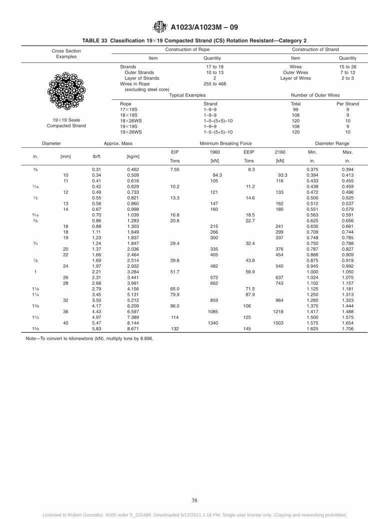
TABLE 33 Classification 19319 Compacted Strand (CS) Rotation Resistant—Category 2
Cross SectionExamples
Construction of Rope Construction of Strand
Item Quantity Item Quantity
19319 SealeCompacted Strand
Strands 17 to 18 Wires 15 to 26Outer Strands 10 to 13 Outer Wires 7 to 12Layer of Strands 2 Layer of Wires 2 to 3
Wires in Rope(excluding steel core)
255 to 468
Typical Examples Number of Outer Wires
Rope Strand Total Per Strand17319S18319S18326WS19319S19326WS
1–9–91–9–91–5–(5+5)–101–9–91–5–(5+5)–10
99108120108120
9910910
Diameter Approx. Mass Minimum Breaking Force Diameter Range
in. [mm] lb/ft [kg/m]EIP 1960 EEIP 2160 Min. Max.
Tons [kN] Tons [kN] in. in.
3⁄8 0.31 0.462 7.55 8.3 0.375 0.39410 0.34 0.509 84.3 93.3 0.394 0.41311 0.41 0.616 105 116 0.433 0.455
7⁄16 0.42 0.629 10.2 11.2 0.438 0.45912 0.49 0.733 121 133 0.472 0.496
1⁄2 0.55 0.821 13.3 14.6 0.500 0.52513 0.58 0.860 147 162 0.512 0.53714 0.67 0.998 160 180 0.551 0.579
9⁄16 0.70 1.039 16.8 18.5 0.563 0.5915⁄8 0.86 1.283 20.6 22.7 0.625 0.656
16 0.88 1.303 215 241 0.630 0.66118 1.11 1.649 266 299 0.709 0.74419 1.23 1.837 300 337 0.748 0.785
3⁄4 1.24 1.847 29.4 32.4 0.750 0.78820 1.37 2.036 335 376 0.787 0.82722 1.66 2.464 405 454 0.866 0.909
7⁄8 1.69 2.514 39.8 43.8 0.875 0.91924 1.97 2.932 482 540 0.945 0.992
1 2.21 3.284 51.7 56.9 1.000 1.05026 2.31 3.441 572 637 1.024 1.07528 2.68 3.991 662 743 1.102 1.157
11⁄8 2.79 4.156 65.0 71.5 1.125 1.18111⁄4 3.45 5.131 79.9 87.9 1.250 1.313
32 3.50 5.212 859 964 1.260 1.32313⁄8 4.17 6.209 96.0 106 1.375 1.444
36 4.43 6.597 1085 1218 1.417 1.48811⁄2 4.97 7.389 114 125 1.500 1.575
40 5.47 8.144 1340 1503 1.575 1.65415⁄8 5.83 8.671 132 145 1.625 1.706
Note—To convert to kilonewtons (kN), multiply tons by 8.896.
A1023/A1023M – 09
38
Licensed to Robert Gonzalez. ANSI order X_225488. Downloaded 5/12/2011 1:16 PM. Single user license only. Copying and networking prohibited.
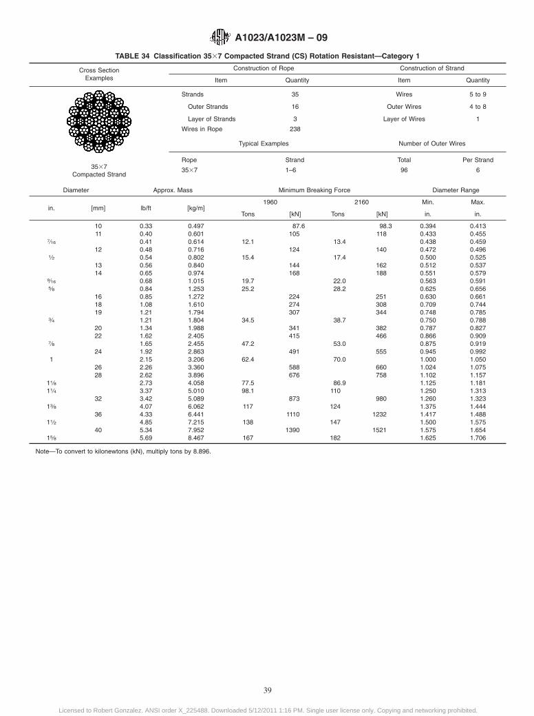
TABLE 34 Classification 3537 Compacted Strand (CS) Rotation Resistant—Category 1
Cross SectionExamples
Construction of Rope Construction of Strand
Item Quantity Item Quantity
3537Compacted Strand
Strands 35 Wires 5 to 9
Outer Strands 16 Outer Wires 4 to 8
Layer of Strands 3 Layer of Wires 1
Wires in Rope 238
Typical Examples Number of Outer Wires
Rope Strand Total Per Strand
3537 1–6 96 6
Diameter Approx. Mass Minimum Breaking Force Diameter Range
in. [mm] lb/ft [kg/m]1960 2160 Min. Max.
Tons [kN] Tons [kN] in. in.
10 0.33 0.497 87.6 98.3 0.394 0.41311 0.40 0.601 105 118 0.433 0.455
7⁄16 0.41 0.614 12.1 13.4 0.438 0.45912 0.48 0.716 124 140 0.472 0.496
1⁄2 0.54 0.802 15.4 17.4 0.500 0.52513 0.56 0.840 144 162 0.512 0.53714 0.65 0.974 168 188 0.551 0.579
9⁄16 0.68 1.015 19.7 22.0 0.563 0.5915⁄8 0.84 1.253 25.2 28.2 0.625 0.656
16 0.85 1.272 224 251 0.630 0.66118 1.08 1.610 274 308 0.709 0.74419 1.21 1.794 307 344 0.748 0.785
3⁄4 1.21 1.804 34.5 38.7 0.750 0.78820 1.34 1.988 341 382 0.787 0.82722 1.62 2.405 415 466 0.866 0.909
7⁄8 1.65 2.455 47.2 53.0 0.875 0.91924 1.92 2.863 491 555 0.945 0.992
1 2.15 3.206 62.4 70.0 1.000 1.05026 2.26 3.360 588 660 1.024 1.07528 2.62 3.896 676 758 1.102 1.157
11⁄8 2.73 4.058 77.5 86.9 1.125 1.18111⁄4 3.37 5.010 98.1 110 1.250 1.313
32 3.42 5.089 873 980 1.260 1.32313⁄8 4.07 6.062 117 124 1.375 1.444
36 4.33 6.441 1110 1232 1.417 1.48811⁄2 4.85 7.215 138 147 1.500 1.575
40 5.34 7.952 1390 1521 1.575 1.65415⁄8 5.69 8.467 167 182 1.625 1.706
Note—To convert to kilonewtons (kN), multiply tons by 8.896.
A1023/A1023M – 09
39
Licensed to Robert Gonzalez. ANSI order X_225488. Downloaded 5/12/2011 1:16 PM. Single user license only. Copying and networking prohibited.
SUMMARY OF CHANGES
Committee A01 has identified the location of selected changes to this standard since the last issue(A1023/A1023M – 07) that may impact the use of this standard. (Approved October 1, 2009.)
(1) Revised tables Table 12, Table 13, Table 14, Table 15,Table 20, Table 21, Table 25, Table 26, and Table 27.
(2) Corrected typographical error in heading of Table 18.
ASTM International takes no position respecting the validity of any patent rights asserted in connection with any item mentionedin this standard. Users of this standard are expressly advised that determination of the validity of any such patent rights, and the riskof infringement of such rights, are entirely their own responsibility.
This standard is subject to revision at any time by the responsible technical committee and must be reviewed every five years andif not revised, either reapproved or withdrawn. Your comments are invited either for revision of this standard or for additional standardsand should be addressed to ASTM International Headquarters. Your comments will receive careful consideration at a meeting of theresponsible technical committee, which you may attend. If you feel that your comments have not received a fair hearing you shouldmake your views known to the ASTM Committee on Standards, at the address shown below.
This standard is copyrighted by ASTM International, 100 Barr Harbor Drive, PO Box C700, West Conshohocken, PA 19428-2959,United States. Individual reprints (single or multiple copies) of this standard may be obtained by contacting ASTM at the aboveaddress or at 610-832-9585 (phone), 610-832-9555 (fax), or [email protected] (e-mail); or through the ASTM website(www.astm.org). Permission rights to photocopy the standard may also be secured from the ASTM website (www.astm.org/COPYRIGHT/).
A1023/A1023M – 09
40
Licensed to Robert Gonzalez. ANSI order X_225488. Downloaded 5/12/2011 1:16 PM. Single user license only. Copying and networking prohibited.