Embed Size (px)
Citation preview

SSttaannddaarrdd SSppeecciiffiiccaattiioonnss aanndd DDrraawwiinnggss Springville City Public Works
May 2018
SPRINGVILLE CITY STANDARD SPECIFICATIONS
i
STANDARD SPECIFICATIONS
TABLE OF CONTENTS
CHAPTER 1 - GENERAL REQUIREMENTS ................................................................................................... 1
1.1 PURPOSE OF DOCUMENTS .................................................................................................... 1 1.2 ENCROACHMENT PERMIT, FEES AND BONDING REQUIRED ........................................ 1
1.2.1 Forward: ............................................................................................................................. 1 1.2.2 Policies: .............................................................................................................................. 1 1.2.3 General Conditions: ........................................................................................................... 4 1.2.4 Protection of Public During Construction: ......................................................................... 6 1.2.5 Excavation Operation: ........................................................................................................ 7 1.2.6 Backfilling Operation: ........................................................................................................ 8 1.2.7 Resurfacing: ....................................................................................................................... 8 1.2.8 Environmental Control: ...................................................................................................... 9 1.2.9 Guarantees:......................................................................................................................... 10
1.3 CONTRACTOR AND CONSTRUCTION PLAN APPROVAL ................................................ 11 1.4 PRE-CONSTRUCTION MEETINGS ......................................................................................... 11 1.5 CONSTRUCTION OF PUBLIC IMPROVEMENTS ................................................................. 12
1.5.1 Responsibility of the Developer: ........................................................................................ 12 1.5.2 Construction Survey: .......................................................................................................... 12 1.5.3 Inspections: ........................................................................................................................ 12 1.5.4 Notification of Needed Inspections: ................................................................................... 12 1.5.5 Definition of “City Engineer / Public Works Representative”: .......................................... 13 1.5.6 Conflict: ............................................................................................................................. 13 1.5.7 Variance: ............................................................................................................................ 13 1.5.7 Amendments: ..................................................................................................................... 14 1.5.8 Acceptance of Improvements: ............................................................................................ 14
1.6 ELECTRONIC AND RECORD DRAWINGS ............................................................................ 14 1.7 TEMPORARY SERVICES ......................................................................................................... 14 1.8 CODES AND STANDARDS ...................................................................................................... 14 1.9 STATE AND LOCAL LAWS ..................................................................................................... 14 1.10 COMPLIANCE WITH GOVERNMENTAL REGULATIONS .................................................. 14
1.10.1 United States Occupational Safety and Health Administration Regulations: ................... 14 1.10.2 Utah State Industrial Commission Regulations: ............................................................... 15 1.10.3 City Ordinances: ............................................................................................................... 15 1.10.4 UDOT Requirements: ...................................................................................................... 15 1.10.5 Permits: ............................................................................................................................ 15
1.11 FEDERAL, STATE, AND LOCAL INSPECTING AGENCIES ................................................ 15 1.12 PUBLIC SAFETY AND CONVENIENCE ................................................................................. 15
1.12.1 Compliance with Rules and Regulations: ......................................................................... 15 1.12.2 Road Closures and Obstructions: ..................................................................................... 15 1.12.3 Protection of the Traveling Public: .................................................................................. 16
1.13 CONFINEMENT OF WORK AND ACCESS TO RIGHT-OF-WAY AND
EASEMENTS .............................................................................................................................. 16 1.14 NOTIFICATION OF RESIDENTS ............................................................................................. 16 1.15 WEATHER CONDITIONS ......................................................................................................... 16 1.16 LAND MONUMENTS ................................................................................................................ 16 1.17 SOURCE OF MATERIALS ........................................................................................................ 17 1.18 OPERATION AND MAINTENANCE MANUALS ................................................................... 17 1.19 INTERFERING STRUCTURES, UTILITIES AND FACILITIES ............................................. 17
SPRINGVILLE CITY STANDARD SPECIFICATIONS
ii
1.20 MATERIAL AND COMPACTION TESTING ........................................................................... 17 1.20.1 Guarantee: ....................................................................................................... 18 1.20.2 Test Schedule: ................................................................................................. 18 1.20.3 Duties of Contractor: ....................................................................................... 18
1.21 TELEVISING OF GRAVITY FLOW PIPELINES ..................................................................... 19 1.22 LOT CORNER AND SUBDIVISION MONUMENT ................................................................ 19
CHAPTER 2 - TRENCH EXCAVATION AND BACKFILL ............................................................................ 20
2.1 GENERAL ................................................................................................................................... 20 2.2 SHEETING, BRACING AND SHORING OF EXCAVATIONS ............................................... 20 2.3 CONTROL OF GROUNDWATER ............................................................................................. 20 2.4 TRENCH EXCAVATION ........................................................................................................... 20
2.4.1 Authorized Over-Excavation: ............................................................................................. 20 2.4.2 Unauthorized Over-Excavation: ......................................................................................... 20 2.4.3 Trench Width: .................................................................................................................... 21 2.4.4 Trenches in Embankments: ................................................................................................ 21 2.4.5 Placement of Excavated Material: ...................................................................................... 21 2.4.6 Fine Grading the Trench Bottom: ...................................................................................... 21
2.5 TRENCH BACKFILL ................................................................................................................. 21 2.5.1 Imported Granular Material: .............................................................................................. 22 2.5.2 Foundation Material Placement: ........................................................................................ 23 2.5.3 Pipe Embedment Material Placement: ............................................................................... 23 2.5.4 Granular Backfill Material Placement: ............................................................................... 24 2.5.5 Compaction: ....................................................................................................................... 24
2.6 PRIVATE PROPERTY ACCESS AND RESTORATION ......................................................... 24 2.7 RESTORATION OF CONSTRUCTION SITE ........................................................................... 25 2.8 DEVELOPER/CONTRACTOR'S RESPONSIBILITY ............................................................... 25
CHAPTER 3 - PRESSURE IRRIGATION .......................................................................................................... 26
3.1 GENERAL ................................................................................................................................... 26 3.2 PVC PIPE ................................................................................................................................... 26
3.2.1 Materials: ........................................................................................................................... 26 3.2.2 Joints: ................................................................................................................................. 26 3.2.3 Fittings: .............................................................................................................................. 26 3.2.4 Detectable Caution Tape: ................................................................................................... 26 3.2.5 Tracer Wire: ....................................................................................................................... 26
3.3 RESILIENT SEATED GATE VALVE ....................................................................................... 27 3.4 BUTTERFLY VALVE ................................................................................................................ 27 3.5 VALVE BOXES .......................................................................................................................... 27
3.5.1 Placement of Concrete Collars: .......................................................................................... 27 3.6 PIPE INSTALLATION ............................................................................................................... 27
3.6.1 Cutting:............................................................................................................................... 27 3.6.2 Dewatering of Trench: ....................................................................................................... 28 3.6.3 Laying of Pipe: ................................................................................................................... 28 3.6.4 Joint Restraints: .................................................................................................................. 28 3.6.5 Thrust Blocking: ................................................................................................................ 28 3.6.6 Connections to Existing Irrigation Lines: ........................................................................... 28 3.6.7 Pipe Embedment: ............................................................................................................... 29
3.7 PRESSURE IRRIGATION SERVICE CONNECTION ............................................................. 29 3.7.1 Extent and Locations of Laterals: ....................................................................................... 29 3.7.2 Connection to Main: ........................................................................................................... 29 3.7.3 Polyethylene Tubing: ......................................................................................................... 29 3.7.4 Compression Connection: .................................................................................................. 30 3.7.5 Ball Valve Curb Stop: ........................................................................................................ 30
SPRINGVILLE CITY STANDARD SPECIFICATIONS
iii
3.7.6 Service Box: ....................................................................................................................... 31 3.7.7 PVC Pipe: .......................................................................................................................... 31 3.7.8 Service Pipe Installation: .................................................................................................... 31
3.8 PIPELINE TESTING AND FLUSHING .................................................................................... 31 3.8.1 Pressure Test: ..................................................................................................................... 31 3.8.2 Leakage Test: ..................................................................................................................... 32 3.8.3 Acceptance of Testing: ....................................................................................................... 33 3.8.4 Flushing: ............................................................................................................................. 33
3.9 AIR RELEASE and VACUUM RELIEF VALVE ...................................................................... 34 3.10 PRESSURE IRRIGATION DRAINS .......................................................................................... 34
CHAPTER 4 - CULINARY WATER ................................................................................................................... 35
4.1 GENERAL ................................................................................................................................... 35 4.2 DUCTILE IRON PIPE................................................................................................................. 35
4.2.1 Materials: ........................................................................................................................... 35 4.2.2 Joints: ................................................................................................................................. 35 4.2.3 Coatings and Linings for Ductile Iron Pipe: ....................................................................... 35 4.2.4 Corrosion Protection and Soil Tests: .................................................................................. 36 4.2.5 Fittings: .............................................................................................................................. 36 4.2.6 Detectable Caution Tape: ................................................................................................... 36 4.2.7 Tracer Wire: ....................................................................................................................... 36
4.3 PVC PIPE .................................................................................................................................... 36 4.3.1 Materials: ........................................................................................................................... 36 4.3.2 Joints: ................................................................................................................................. 37 4.3.3 Fittings: .............................................................................................................................. 37 4.3.4 Detectable Caution Tape: ................................................................................................... 37 4.3.5 Tracer Wire: ....................................................................................................................... 38
4.4 PIPE INSTALLATION ............................................................................................................... 38 4.4.1 Cutting:............................................................................................................................... 38 4.4.2 Dewatering of Trench: ....................................................................................................... 38 4.4.3 Laying of Pipe: ................................................................................................................... 38 4.4.4 Pipe Bedding: ..................................................................................................................... 38 4.4.5 Thrust Blocking: ................................................................................................................ 39 4.4.6 Connections to Existing Water Lines: ................................................................................ 39
4.5 WATER SERVICE LATERALS ................................................................................................. 39 4.5.1 Extent and Locations of Laterals: ....................................................................................... 39 4.5.2 Connection to Main: ........................................................................................................... 40 4.5.3 Meter Setter, Box and Cover: ............................................................................................. 40 4.5.4 Special Joints and Fittings: ................................................................................................. 40 4.5.5 Flushing, Testing and Disinfecting: .................................................................................... 41 4.5.6 Damage and Repair of Water Mains and Appurtenances: .................................................. 41
4.6 FLUSHING, DISINFECTING, AND TESTING OF WATER MAINS...................................... 41 4.6.1 Disinfection: ....................................................................................................................... 41 4.6.2 Bacteria Test ...................................................................................................................... 42 4.6.3 Flushing: ............................................................................................................................. 42 4.6.4 Pressure Test: ..................................................................................................................... 42 4.6.5 Leakage Test: ..................................................................................................................... 43
4.7 RESILIENT SEATED GATE VALVE ....................................................................................... 44 4.8 BUTTERFLY VALVE ................................................................................................................ 44 4.9 VALVE BOXES .......................................................................................................................... 44
4.9.1 Placement of Concrete Collars ........................................................................................... 44 4.10 FIRE HYDRANTS ...................................................................................................................... 45 4.11 AIR RELEASE and VACUUM RELIEF VALVE ..................................................................... 45
SPRINGVILLE CITY STANDARD SPECIFICATIONS
iv
CHAPTER 5 - STORM DRAIN & IRRIGATION .............................................................................................. 46
5.1 GENERAL ................................................................................................................................... 46 5.2 MINIMUM SIZES ....................................................................................................................... 46 5.3 PIPE ............................................................................................................................................. 46
5.3.1 Reinforced Concrete Pipe: ................................................................................................. 46 5.3.2 Corrugated High Density Polyethylene Pipe: ..................................................................... 46
5.4 PIPE LAYING ............................................................................................................................. 47 5.4.1 Reinforced Concrete Pipe: ................................................................................................. 47 5.4.2 Corrugated High Density Polyethylene Pipe: ..................................................................... 47
5.5 INSTALLATION REQUIREMENTS FOR LINE AND GRADE .............................................. 47 5.6 GRAVEL FOUNDATION FOR PIPE ......................................................................................... 47 5.7 PIPE BEDDING .......................................................................................................................... 48 5.8 CLEANING AND TELEVISING ................................................................................................ 48 5.9 TESTS .......................................................................................................................................... 48
5.9.1 Air Testing: ........................................................................................................................ 48 5.9.2 GO/NO-GO” Mandrel Proof Testing (For HDPE Pipe Only): .......................................... 48
5.10 MANHOLES OR JUNCTION BOXES ....................................................................................... 49 5.10.1 Setting of Manhole Frames and Covers and Placement of Concrete Collars ................... 49
5.11 PIPE CONNECTIONS ................................................................................................................ 49
CHAPTER 6 - SANITARY SEWER .................................................................................................................... 50
6.1 GENERAL ................................................................................................................................... 50 6.2 PIPE ............................................................................................................................................. 50 6.3 FITTINGS .................................................................................................................................... 50 6.4 PIPE LAYING ............................................................................................................................. 50 6.5 GRAVEL FOUNDATION FOR PIPE ......................................................................................... 50 6.6 INSTALLATION REQUIREMENTS FOR LINE AND GRADE .............................................. 50 6.7 PIPE BEDDING .......................................................................................................................... 51 6.8 CLEANING AND TELEVISING ................................................................................................ 51 6.9 TESTS .......................................................................................................................................... 51
6.9.1 Infiltration Test: ................................................................................................................. 51 6.9.2 Exfiltration Test: ................................................................................................................ 51 6.9.3 Air Testing: ........................................................................................................................ 52 6.9.4 “Go/No-Go” Mandrel Proof Testing: ................................................................................. 52
6.10 MANHOLE CONNECTIONS ..................................................................................................... 52 6.11 SEWER LATERAL CONNECTIONS ........................................................................................ 52 6.12 SEWER SERVICE LATERALS ................................................................................................. 53
6.12.1 Extent of Laterals and Location of Laterals: .................................................................... 53 6.12.2 Excavation and Backfill: .................................................................................................. 53 6.12.3 Pipe: ................................................................................................................................. 53 6.12.4 Cover Over Sewer Lateral Lines: ..................................................................................... 53 6.12.5 Testing: ............................................................................................................................ 53 6.12.6 Damage and Repairs of Sewers and Appurtenances: ....................................................... 53
6.13 ORANGEBURG PIPE ................................................................................................................. 54
CHAPTER 7 - MANHOLES ................................................................................................................................. 55
7.1 GENERAL ................................................................................................................................... 55 7.1.1 Manhole Sizing: ................................................................................................................. 55
7.2 CONCRETE BASE ..................................................................................................................... 55 7.3 WALL AND CONE SECTIONS ................................................................................................. 55 7.4 DROP MANHOLES .................................................................................................................... 55 7.5 MANHOLE RINGS AND COVERS ........................................................................................... 55
7.5.1 Setting of Manhole Frames and Covers and Placement of Concrete Collars ..................... 56 7.6 CONNECTIONS TO EXISTING SEWER MAINS .................................................................... 56
SPRINGVILLE CITY STANDARD SPECIFICATIONS
v
7.7 CONNECTIONS TO EXISTING SEWER MANHOLES .......................................................... 56 7.8 GREASE INTERCEPTORS ........................................................................................................ 56 7.9 POLYMER MANHOLES - HYDROGEN SULFIDE PROTECTION ....................................... 57
CHAPTER 8 - EARTHWORK ............................................................................................................................. 58
8.1 GENERAL ................................................................................................................................... 58 8.2 EXCAVATION FOR MANHOLES, BOXES, AND OTHER STRUCTURES .......................... 58 8.3 GRANULAR FOUNDATION BORROW .................................................................................. 58 8.4 BACKFILL AROUND STRUCTURES ...................................................................................... 58 8.5 CONSTRUCTION OF EMBANKMENTS AND FILLS ............................................................ 58
8.5.1 Foundation Preparation: ..................................................................................................... 58 8.5.2 Placement: .......................................................................................................................... 59 8.5.3 Borrow: .............................................................................................................................. 60
8.6 COMPACTION OF MATERIALS .............................................................................................. 60 8.6.1 Under Roadways: ............................................................................................................... 60 8.6.2 Under Sidewalks and Driveways: ....................................................................................... 60
8.7 REMOVAL OF DEFECTIVE FILL AND PLACEMENT OF ACCEPTABLE FILL ................ 61
CHAPTER 9 - PORTLAND CEMENT CONCRETE ........................................................................................ 62
9.1 GENERAL ................................................................................................................................... 62 9.2 MATERIALS ............................................................................................................................... 62
9.2.1 Portland Cement: ................................................................................................................ 62 9.2.2 Aggregate: .......................................................................................................................... 62 9.2.3 Water: ................................................................................................................................. 63 9.2.4 Air-Entraining Agent: ......................................................................................................... 63 9.2.5 Water-Reducing and Set-Retarding Admixtures: ............................................................... 63 9.2.6 Curing compound: .............................................................................................................. 63
9.3 CLASS OF CONCRETE ............................................................................................................. 63 9.4 COMPOSITION OF CONCRETE .............................................................................................. 63
9.4.1 Aggregate: .......................................................................................................................... 63 9.4.2 Water: ................................................................................................................................. 64 9.4.3 Air-Content: ....................................................................................................................... 64 9.4.4 Admixtures: ........................................................................................................................ 64
9.5 DESIGN OF THE CONCRETE MIX ......................................................................................... 64 9.6 OBSERVATION AND TESTING .............................................................................................. 64
9.6.1 Concrete Testing Requirements: .................................................................................... 64 9.6.2 Evaluation of Test Results: ............................................................................................ 65 9.6.3 Acceptance: .................................................................................................................... 65
9.7 HANDLING AND MEASUREMENT OF MATERIALS .......................................................... 65 9.8 MIXERS AND MIXING ............................................................................................................. 66 9.9 FORMS ........................................................................................................................................ 66 9.10 PREPARATION OF FORMS AND SUBGRADE ...................................................................... 66 9.11 CONVEYING .............................................................................................................................. 67 9.12 PLACING .................................................................................................................................... 67 9.13 CONSTRUCTION JOINTS ........................................................................................................ 67 9.14 EXPANSION AND CONTRACTION JOINTS .......................................................................... 68 9.15 WATERSTOP.............................................................................................................................. 68 9.16 REMOVAL OF FORMS ............................................................................................................. 68 9.17 FINISHING FORMED SURFACES ........................................................................................... 68 9.18 FINISHING UNFORMED SURFACES ..................................................................................... 69 9.19 CURING AND PROTECTION ................................................................................................... 69 9.20 REMOVAL OR REPAIR ............................................................................................................ 69 9.21 CONCRETING IN COLD WEATHER ....................................................................................... 70 9.22 CONCRETING IN HOT WEATHER ......................................................................................... 70
SPRINGVILLE CITY STANDARD SPECIFICATIONS
vi
CHAPTER 10 - CONCRETE REINFORCEMENT ........................................................................................... 71
10.1 GENERAL ................................................................................................................................... 71 10.2 FABRICATION AND PLACING STEEL REINFORCEMENT ................................................ 71
10.2.1 Fabrication: ...................................................................................................................... 71 10.2.2 Clearances: ....................................................................................................................... 71 10.2.3 Support: ......................................................................................................... 72 10.2.4 Splicing: ........................................................................................................................... 72
10.3 EPOXY COATING ..................................................................................................................... 72 10.3.1 Prequalify all Coatings: .................................................................................................... 72 10.3.2 Coat Bars as Specified: .................................................................................................... 73 10.3.3 Handling: .......................................................................................................................... 73
10.4 FIELD CUTTING EPOXY-COATED BARS ............................................................................. 73 10.4.1 Cutting:............................................................................................................................. 73 10.4.2 Repairing: ......................................................................................................................... 73
10.5 FIBER REINFORCEMENT ........................................................................................................ 73
CHAPTER 11 - RESTORATION OF SURFACE IMPROVEMENTS ............................................................. 74
11.1 GENERAL ................................................................................................................................... 74 11.2 FIELD VERIFICATION OF IMPROVEMENTS ....................................................................... 74 11.3 REMOVAL OF PAVEMENT, SIDEWALKS, CURBS, ETC. ................................................... 74 11.4 MATERIALS ............................................................................................................................... 74 11.5 RESTORING BITUMINOUS OR CONCRETE STREET SURFACES .................................... 74
11.5.1 Before Excavation: ........................................................................................................... 74 11.5.2 Temporary Graded Surface: ............................................................................................. 74 11.5.3 Preparation for Paving: .................................................................................................... 75 11.5.4 Bituminous Surface: ......................................................................................................... 75 11.5.5 Special Requirements for Longitudinal Trench Repair: ................................................... 75
11.6 UTILITY POTHOLES-KEYHOLE METHOD .......................................................................... 76 11.6.1 Pothole Excavation: ......................................................................................... 76 11.6.2 Pothole Backfill: .............................................................................................. 76 11.6.3 Bonding Agent:................................................................................................ 76 11.6.4 Pavement Restoration: ..................................................................................... 77 11.6.5 Deficiencies: .................................................................................................... 77
11.7 GRAVEL SURFACE ................................................................................................................... 77 11.7.1 Layer Thickness: .............................................................................................. 77 11.7.2 Placement: ....................................................................................................... 77 11.7.3 Gradation: ........................................................................................................ 78
11.8 MISCELLANEOUS IMPROVEMENTS .................................................................................... 78 11.9 RESTORATION OF SURFACES ............................................................................................... 78 11.10 CLEANUP ................................................................................................................................... 78 11.11 PAVEMENT MARKINGS .......................................................................................................... 78 11.12 LANDSCAPE RESTORATION .................................................................................................. 78
CHAPTER 12 - ROADWAY CONSTRUCTION ................................................................................................ 80
12.1 GENERAL ................................................................................................................................... 80 12.2 MILLING / PULVERIZING ....................................................................................................... 80 12.3 EARTHWORK ............................................................................................................................ 80 12.4 ROADWAY EXCAVATION ...................................................................................................... 80 12.5 SUBGRADE PREPARATION .................................................................................................... 80 12.6 GRANULAR BORROW ............................................................................................................. 80 12.7 UNTREATED BASE COURSE .................................................................................................. 81 12.8 ASPHALT PAVEMENT ............................................................................................................. 81 12.9 ADJUSTING MANHOLES AND BOXES TO FINAL GRADE & INSTALLING
CONCRETE COLLAR ................................................................................................................ 82
SPRINGVILLE CITY STANDARD SPECIFICATIONS
vii
12.10 ADJUSTING VALVE BOXES TO FINAL GRADE & INSTALLING CONCRETE
COLLAR ...................................................................................................................................... 82
CHAPTER 13 - CONCRETE PLACEMENT ...................................................................................................... 84
13.1 GENERAL ................................................................................................................................... 84 13.2 CONCRETE ................................................................................................................................ 84 13.3 GRADE ........................................................................................................................................ 84 13.4 FORMS ........................................................................................................................................ 84 13.5 SUBGRADE PREPARATION .................................................................................................... 84 13.6 CONSTRUCTION OF CURB, GUTTER AND SIDEWALK .................................................... 84
13.6.1 Matching Existing Monolithic Curb, Gutter and Sidewalk .............................................. 85 13.6.2 Curb and Gutter Joints ..................................................................................................... 85 13.6.3 Sidewalk Joints................................................................................................................. 85 13.6.4 Finishing of Sidewalks ..................................................................................................... 85 13.6.5 Finishing of Curb and Gutter ............................................................................................ 85
13.7 CONCRETE DRIVE APPROACH ............................................................................................. 85 13.8 ADA (AMERICANS WITH DISABILITIES ACT) STANDARDS IN PUBLIC
RIGHTS-OF-WAY ...................................................................................................................... 86
CHAPTER 14 - UTAH DEPARTMENT OF TRANSPORTATION RIGHTS-OF-WAY ............................... 87
14.1 GENERAL ................................................................................................................................... 87
CHAPTER 15 - CASINGS ..................................................................................................................................... 88
15.1 GENERAL ................................................................................................................................... 88
CHAPTER 16 - FLOWABLE FILL (CLSM) ...................................................................................................... 89
16.1 GENERAL ................................................................................................................................... 89
SPRINGVILLE CITY STANDARD SPECIFICATIONS CHAPTER 1 – GENERAL REQUIREMENTS
1
CHAPTER 1 - GENERAL REQUIREMENTS
1.1 PURPOSE OF DOCUMENTS The purpose of these Standard Specifications and Standard Drawings is to govern any work done or improvements installed within Public right-of-ways or public easements. Construction work shall comply with Springville City Codes, specifically Title 11 Development Code and Title 14 Subdivision Code. Developers/Contractors should thoroughly read and understand these specifications and standards before constructing public improvements. Anything not specified in these specifications shall be governed by the most current revision of the Utah APWA specifications. If conflicts arise, the Developer/Contractor shall notify the City Engineer or his representative for final direction. The Developer/Contractor shall contact Public Works/City Engineering at the Springville City Offices, 110 South Main Street, Springville, Utah 84663 for all matters dealing with construction work within a City right-of-way or with any work connecting onto a City utility. SPECIAL PERMITS AND BONDING ARE REQUIRED FOR ALL SUCH WORK.
1.2 ENCROACHMENT PERMIT, FEES AND BONDING REQUIRED It shall be unlawful to do any construction within the public right-of-way, within a public easement, or perform any work on public infrastructure in the City of Springville without an Encroachment Permit from the City to do so. The City of Springville and all utility companies are bound by these standard specifications. No work shall be started until a permit is secured. In order to obtain an Encroachment Permit, the Developer’s/Contractor’s authorized signature is required. If a contract to do such work for the City has been finalized, the contract fulfills this permit requirement.
1.2.1 Forward:
1) Statement of Intent: The purpose of this section is to describe Springville City Ordinance #10-8 and
policies for issuing permits to work in the public right-of-way. These permits control excavation and
construction operations. It is also implemented to cover special requirements for work in general,
maintenance, private construction, and additions to utility systems in the public right-of-way. Nothing
in this document will be construed as taking precedence over Ordinance #10-8.
a. Application: All conditions in this specification apply to all construction and maintenance
work performed in the public right-of-way.
b. Revisions: This specification is subject to revision. The latest revision will always apply.
c. For the purpose of this specification, certain words and phrases are defined as in Springville
City Ordinance #10-8 unless it shall be apparent from the context that different meaning is
intended.
1.2.2 Policies:
1) Policy for Permit Required for Work in the Public Right-of-Way: It shall be unlawful to: interrupt or
alter vehicular and pedestrian traffic, construct, reconstruct, or alter any opening, excavation, tunnel,
sidewalk, curb gutter, driveway, street, or to perform any other work of any kind to the public right-of-
way which will result in physical alteration thereof unless such person shall first have obtained a permit
for the performance of such work and said work shall be performed in conformity with the terms and
provisions of Springville City Standard Specifications and Ordinance #10-8 and of the permit or
permits issued hereunder, accept as hereinafter specifically provided.
2) Policy for Permit Required for Occupation of Street with Building Material: It shall be unlawful for any
person to occupy or use any portion of a public right-of-way for the storage of construction or
landscaping material and/or equipment without first making application for and receiving a permit from
the City. The permit may set forth such restrictions as required by ordinance or by the City Engineer.
No fence construction pursuant to these ordinances and no building material shall remain in place in
SPRINGVILLE CITY STANDARD SPECIFICATIONS CHAPTER 1 – GENERAL REQUIREMENTS
2
any public right-of-way after the ending date of the permit, unless said permit is extended by the City
Engineer.
3) Policy for Permit Required for Scaffold, Barricades Over/or in the Public Right-of-Way: It shall be
unlawful for any person to erect, maintain, or use any scaffold, fence or any other temporary structure
over or in the public right-of-way without first obtaining a permit for that purpose and paying the fee
for such permit.
4) Policy for Permit of Water Service Line Replacement: Replacement of water line service from meter
located in the public right-of-way requires a permit.
5) Policy for Required License and Bond: Persons desiring to perform work in the City's public right-of-
way shall be properly licensed in the State of Utah and post a performance bond on a form provided by
the City. A single bond may be posted by a permittee to guarantee performance for one or more permits
if approved by the City Engineer and agreed to, in writing, by the bonding company. Refer to ordinance
#10-8 and consolidated fee schedule.
Note: The City Engineer will review the license type to ensure it is applicable to the work being performed.
Exception: A license shall not be required by the City when the permittee is a property owner performing
work in an area which abuts only his property of residence and the work does not exceed 500 square feet of
drive approach, or 100 linear feet of sidewalk, or installing a sprinkler system.
6) Policy for Applications for Permits: Any person desiring to perform any work of any kind described in
Ordinance #10-8, shall be subject to this specification and shall make application for a permit. Such
application shall be filed with the Public Works/City Engineering Department on the form provided by
the City. Any work involving installation or alteration of a permanent facility or structure in the public
right-of-way will require the filing of engineered plans, traffic plans, and specifications showing the
proposed work in sufficient detail to permit determination of such relationship and compliance, and the
application shall not be deemed approved until such engineered and traffic plans or sketches are filed
and approved. The City Engineer may deny issuance of permits to contractors, utility companies, or
other permit Applicants who have shown by past performance that in the opinion of the City Engineer
they will not consistently conform to this specification, Springville City standard specifications, or the
requirements of ordinance #10-8. City Engineer may also require construction drawings and
specifications for any permit application.
7) Policy for Requirement of Traffic Plan: Prior to City issuing a permit, a traffic plan must be submitted
by the permittee for review and approval by City traffic personnel. Traffic plan is to be in conformance
with current “MUTCD” and approved prior to excavation, construction, or any occupation of the
Public right-of-way.
8) Policy for Commencement of Work: It is unlawful for any person to commence work in the public
right-of-way until the City has approved the application and until a permit has been issued for such
work, except as specifically provided to the contrary in this specification. Duration of the permit shall
be set at the time of issuance of the permit. If work is not completed in forty-five (45) calendar days,
the permit will expire. An extension may be applied for and must be issued prior to commencement of
any further work.
9) Policy for Assessing Permit Fees: The City shall charge and the Permittee shall pay upon issuance of
the permit, fees for costs associated with the work performed under the permit as outlined in the Fee
Schedule adopted by the City Council. Such costs could include costs for reviewing the project and
issuing the permit, inspections of the project, deterioration of the Public Right-of-Way, or diminution
of the useful life of the Public Right-of-Way, and other costs to the City associated with the work to be
done under the permit. All costs shall be assessed in a non-discriminatory manner.
SPRINGVILLE CITY STANDARD SPECIFICATIONS CHAPTER 1 – GENERAL REQUIREMENTS
3
a. City Engineer may waive permit fees as outlined in this specification.
b. Additional charges to cover the reasonable costs and expenses of any required engineering
review, inspection, and work site restoration associated with each undertaking may be charged
by the City to each permittee, in addition to the permit fee.
10) Policy for determining when “Permit Waivers” can be granted: Working in the public right-of-way
without a permit violates Ordinance #10-8, unless the permit is waived by the City Engineer.
Notwithstanding the waivers granted below, all persons working in the public right-of-way shall
properly protect travelers thereon by compliance to the current Manual of Uniform Traffic Control
Devices (MUTCD).
A “permit waiver” does not preclude the requirement of a traffic control plan approved by the City Engineer
when traffic must be routed around or through construction sites. Waivers can be granted by the City
Engineer when any of the following conditions occur:
a. When routine maintenance work which is being done by City, State, County or public utility
company personnel and work does not involve excavations in the City's public right-of-way,
i.e., crack sealing, street resurfacing, snow plowing, sanding, salting, sweeping, garbage
collection, storm drain cleaning, leaf pick up, above-grade work, street striping etc.
b. Landscaping and Landscaping Maintenance.
c. When work involves the installation of a sprinkling system, provided such work does not
require the excavation of park strip area in excess of twenty-four (24) inches and provided
such work does not result in usage of heavy equipment or cause damage to the public facilities
and landscaping in the public right-of-way outside of the work area. Heavy equipment in this
regulation means any tools other than hand tools and a power trencher as described in
landscaping definitions.
d. When minor adjustment to utility meter, valves, or manholes in the park strip area is required
and provided that said adjustment does not result in:
i. excavation in the park strip area in excess of twenty-four (24) inches in depth or
fifteen (15) square feet in area;
ii. Any alterations or damage to the public or private facilities.
iii. the use of heavy equipment,
e. When a permittee allows other contractor or utility companies to perform work in the said
permitted trench limits.
f. When authorized materials are stored in the public right-of-way in compliance to the
provisions of the Manual of Uniform Traffic Control Devices (MUTCD).
11) Policy for Issuing “No Fee” Permits: City Engineer reserves the right to issue “no fee” permits for
work in the public right-of-way. A “no-fee” permit does not preclude the requirement of a traffic
control plan approved by the City Engineer, nor does the fee waiver preclude notification for inspection
forty-eight (48) hours in advance. The City Engineer may waive permit fees or penalties or portions
thereof when he/she determines that such permit fee or penalty:
a. Pertains to construction or rehabilitation of housing for persons whose income is below the
median income level for the City; or
b. Pertains to an encroachment on the Public Right-of-Way involving a beautification project
which furthers specific goals and objectives set forth in the City’s strategic plan, master plans,
or other official documents, including decorative street lighting, building facade lighting,
flower and planter boxes, and landscaping.
12) Policy for Revoking "Permit Waivers" or “No Fee Permits”: "Permit Waivers" and “No Fee Permits”
may be revoked by the City Engineer if the work is unsafe, defective or requires action or supplemental
inspection by the City Engineer. Prior to revocation, the City Engineer will serve written notice
defining the problems encountered and the time the permittee has to correct the problem, except for the
SPRINGVILLE CITY STANDARD SPECIFICATIONS CHAPTER 1 – GENERAL REQUIREMENTS
4
case of immediate safety, where a stop work order will be issued by the City Engineer. If the work is
not satisfactorily corrected, in the time specified, the "permit waiver" will be revoked and the permittee
will be required to secure a "Fee Permit" before proceeding with the work.
13) Policy for Completion of Work by City and Liability for Costs: If the work is unduly delayed by the
permittee, or if the public interest or safety so demands, the City retains the authority to restore the
public right-of-way to active use by providing backfill, road base, asphalt paving, concrete, etc. as
deemed necessary by the City Engineer. The City shall do the work only after written notice has been
given to the permittee and the permittee fails to respond to the City Engineer's request within the time
frame outlined, except when public safety is jeopardized. The time, material, and equipment cost of
such work incurred by the City shall be paid by the permittee or his bond.
14) Policy for Extending Permit Construction Time Limits: Subject to City Engineer's approval, permits
which have expired may be extended up to 30 days from expiration date by submitting to the City
Engineer acceptable reasoning for the delay. Extending time limits beyond normal working hours
requires prior approval by City Engineer.
15) Policy When Construction Practices and Material do not Meet City Specifications: If the City Engineer
determines construction practices and/or materials, i.e., backfill, road base, asphalt and/or concrete, do
not meet City specifications, the City Engineer may:
a. Suspend or revoke the permit;
b. Issue a stop work order;
c. Order removal and replacement of faulty work;
d. Require an extended warranty period;
e. Negotiate a cash settlement to be applied toward future maintenance costs; and/or
f. Make demand upon the permittee’s bond to correct faulty work.
Note: Settlement of trench backfill, road base, asphalt and/or concrete will be incontrovertible evidence of
inadequate compaction of fill material.
16) Policy for Work in the Public Right-of-Way without a Permit: A stop work order may be issued by the
City Engineer directed to any person or persons doing or causing any work to be done in the public
right-of-way without a permit. Any person found to be doing any work in the public right-of-way
without having obtained a permit, as provided in this specification, shall be required to pay a permit fee
as well as penalties outlined in the fee schedule.
17) Policy for Other Highway Permits: Holders of Permits for work on highways owned or under the
jurisdiction of other government entities, but located within the city limits, shall not be required to
obtain permits from the City under the provisions of this ordinance, unless the work extends beyond the
back side of the curb, or beyond any other designated jurisdictional boundary. Any City permit shall
not be construed to permit or allow work on another jurisdiction roadway within the City.
1.2.3 General Conditions:
1) Right-of-way Improvement Drawings: Right-of-way improvement drawings shall conform with all
respects to the City Engineers Design and Platting Standard Regulations. The City Engineer requires
one (1) drawing showing proposed changes to curb, gutter, sidewalk, street pavement, or drainage
facilities. A drawing and calculation for Surface and Storm Water Runoff must be included.
2) Utility Drawing Requirements: Whenever the work involves the extension, placement, or the relocation
of a utility facility one (1) copy of the drawing shall be submitted to the City Engineer which details the
location and type of proposed facility. Work involving maintenance of existing facility does not require
SPRINGVILLE CITY STANDARD SPECIFICATIONS CHAPTER 1 – GENERAL REQUIREMENTS
5
a drawing. A drawing showing all existing utility lateral locations, sidewalk, edge of oil, and side lot
lines is required on the permit form for any new laterals.
3) Permit and Drawings at Job Site: When the work is in progress, the permittee shall have at the work site
a copy of the permit, traffic control plan and City approved drawings.
4) Preconstruction Meeting: When trench length will equal or exceed fifty (50) linear feet or as
determined by City Engineer, the permittee is required to schedule and attend a preconstruction
meeting with City personnel prior to construction.
5) Emergency Work: Maintenance of pipelines or facilities in the public right-of-way may proceed
without a permit when emergency circumstances demand the work be done immediately provided a
permit could not reasonably have been obtained beforehand. In the event that emergency work is
commenced on or within any Public Right-of-Way of the City during regular business hours, the City
Engineer shall be notified within one-half hour from the time the work is commenced. The person
commencing and conducting such work shall take all necessary safety precautions for the protection of
the public and the direction and control of traffic, and shall insure that work is accomplished according
to City Engineering Regulations, the Manual on Uniform Traffic Control Devices (MUTCD) and other
applicable laws, regulations, or generally recognized practices in the industry.
6) Notification: It will be the responsibility of the permittee to notify Public Works, public utilities and
businesses and residents affected by the work. Permittee shall coordinate work around school zones,
garbage collection, postal service, and residents’ homes. Except as otherwise allowed in emergency or
road closure situations, Public Works will be notified by the permittee forty-eight (48) hours, prior to
commencing work. The following information will be provided by phone: permit number, name, and
telephone number of permittee, date/time work is to commence and cease, and location of work. For
road closures permittee will be required to notify Fire Department and Police Department at least 48
hours in advance of all closures. Requirements and notifications shall be in accordance with Section
1.5.2.
7) Resurfacing Time Limits:
a. Arterial or collector street pavement surfaces must be replaced within three (3) calendar days
of excavation or on the same day in which backfill is completed. All other streets must be
resurfaced within seven calendar days from beginning of excavation or on the same day in
which backfill is completed. If work is expected to exceed the above duration, the permittee
shall submit a detailed construction schedule for approval. The schedule will address means
and methods to minimize traffic disruption and complete the construction as soon as
reasonably possible. Work shall not proceed until the schedule is approved by the City
Engineer and shall cease if the schedule is not maintained. In the event that the construction
schedule or resurfacing time limit is exhausted and the work site is hazardous to citizens or
impeding traffic, the City will take the necessary steps to make the work site safe and impose
penalties daily, as outlined in the fee schedule.
b. Submittal: Upon the City's request, the permittee shall provide certification from an approved
material testing laboratory that the materials to be installed under permit are within the City's
specification. Only City approved materials shall be used in the work.
8) Testing: Laboratory testing for materials, compliance, densities, and strength are the responsibility of
the permittee. Testing service must be in accordance with Springville City standard specifications;
Section 1.20. The City Engineer may require additional inspection or material testing as needed. At the
City Engineer’s discretion, testing requirements may be reduced based upon frequency of work
performed in the City and successful testing performance in the past. All materials shall be tested for
conformance to Springville City Standards, Specifications, and Drawings. Should it be necessary for
the City to perform compliance testing, the City shall back charge the permittee for additional testing
SPRINGVILLE CITY STANDARD SPECIFICATIONS CHAPTER 1 – GENERAL REQUIREMENTS
6
performed should any testing reveal noncompliance with City specifications. The back charge rate shall
be the cost of time and equipment to conduct the testing. The City Engineer shall not back charge
permittee if the testing confirms compliance with the City specifications.
9) Preconstruction Photographs/Video of Existing Public Right-of-Way Improvements: Prior to
commencing the permit work, the permittee is encouraged to secure video tape or photographs which
positively identify the condition and existing damages to the public right-of-way improvements such as
curbing, sidewalk, landscaping and asphalt surfaces etc.
10) Maintenance of Drainage Channels: Existing drainage channels such as pipes, gutters, or ditches shall
be kept free of dirt, construction materials, or other debris such that natural flow will not be interrupted.
When it is necessary to block or otherwise impede flow of the drainage channel, a proposed method of
maintaining the flow must be submitted for approval by the City Engineer prior to a blockage of the
channel. Permittee shall not allow dirt or other debris from his work to enter the City's storm drain
system. Failure to comply may result in a penalty equal to cost incurred to correct or prevent damage.
State and Federal penalties may be imposed as well.
11) Failure to Comply; Default in Performance: Any permit may be revoked or suspended and a stop work
order issued by the City Engineer, after notice to the permittee for:
a. Violation of any condition of the permit, the bond, or of any provisions of Springville City
Ordinance
b. Violation of any provision of any other ordinance of the City or law relating to the work; or
c. Existence of any condition or the doing of any act which does constitute, may constitute, or
cause a condition endangering life or property.
A suspension or revocation by the City Engineer, and a stop work order, shall take effect immediately upon
entry thereof by the City Engineer and notice to the Person performing the work in the Public Right-of-
Way. Notice to the Person performing the work shall be accomplished when the City Engineer has posted a
stop work order at the location of the work. Subsequent to posting a stop work order, written notice will be
mailed, return receipt requested, to the address indicated by the Permittee on the permit.
Whenever the City Engineer finds that a default has occurred in the performance or any term or condition of
the permit, written notice thereof may be given to the principal and to the surety on the bond. Such notice
shall state the work to be done, the estimated cost thereof, and the period of time deemed by the City
Engineer to be reasonably necessary for the completion of the work.
In the event that the surety (or principal), within a reasonable time following the giving of such notice
(taking into consideration the exigencies of the situation, the nature of the work, the requirements of public
safety and for the protection of Persons and property) fails either to commence and cause the required work
to be performed with due diligence, or to indemnify the City for the cost of doing the work, as set forth in
the notice, the City may perform the work, at the discretion of the City Engineer, with City forces or
contract forces or both, and suit may be commenced by the City against the Permittee (contractor) and
bonding company and such other Persons as may be liable, to recover the entire amount due to the City,
including attorney fees, on account thereof, in the event cash has been deposited, and suit brought for the
balance due, if any.
1.2.4 Protection of Public During Construction:
1) Conformance to Existing Laws: The permittee shall be responsible for being fully informed of all
Federal, State, and local laws, ordinances, rules and regulation which, in any manner, affect the work,
and at all times shall observe and comply with such laws, ordinances, rules and regulations.
2) Traffic Interruption: Construction operations will be conducted in a manner that will minimize
interference or interruption of roadway traffic, except during emergency conditions, or. Construction
SPRINGVILLE CITY STANDARD SPECIFICATIONS CHAPTER 1 – GENERAL REQUIREMENTS
7
operations such as excavation, backfill, and pavement restoration on arterial/major collector streets shall
be discouraged during peak traffic hours of 7:00 to 9:00 a.m. and 3:00 to 6:00 p.m. unless authorized in
writing by the City Engineer. Permittee shall notify all local Emergency Response Services in the City
forty-eight (48) hours in advance of all road closures.
3) Manual of Uniform Traffic Control Devices: All provisions of the current "MUTCD" shall be adhered to.
This manual provides regulations concerning traffic control, construction barricades, road closures,
public and private access, and traffic control signing. Traffic control devices, as required by the
"MUTCD", must be in place before traffic disturbance or excavation begins. The devices shall be
maintained throughout the construction period and not removed until all equipment and materials are
removed, excavation is backfilled, and temporary or permanent surface is installed. Traffic Engineer may
require certified traffic control personnel during set up and tear-down of all traffic control devices.
Lighted early warning arrow boards will be required on all major arterial and collector streets. The
permittee shall not obstruct the view of any traffic control devices. All disturbed traffic control devices
shall be immediately replaced, cleaned or repaired as directed by the City.
4) Public Access: Permittee shall provide free and unobstructed access to all pedestrian crosswalks,
handicap access ramps, driveways, mailboxes, trash receptacles, fire hydrants, water gates, valves,
manholes, drainage or other public service structures and property that may be required for emergency
use. Permittee shall not remove such public service facilities and property or relocate same without
proper coordination with the authorities charged with control and maintenance of same. Barricades in
conformance with "MUTCD" or covered walkways for the protection of the general public shall be
provided whenever any work or storage of materials is being done.
5) Private Access: Temporary, all-weather roadways, driveways, walks, ADA access ramps and private
rights-of-way for vehicles and pedestrians shall be constructed and continuously maintained by the
permittee when public facilities are disturbed or when required by this specification or the permit.
6) Contractor Information: When personnel and equipment are not on-site, permittee shall clearly post on
barricades in letters two (2) inches high, emergency information consisting of the name and emergency
telephone number of permittee, bearing such information, be placed at every job site and maintained until
the work is complete and formally accepted by the City. Copies of the permit shall be available from the
City Engineer and be open to public inspection during office hours.
7) Right-of-Way Excavation in Winter: Excavation of City right-of-way during winter months (herein as
defined as October 15 to April 15) will be allowed only if the work is a new service connection, required
maintenance, emergency, or otherwise approved by the City Engineer. Permanent repair of City right-of-
way excavated in the winter may be delayed for 60 days or 90 days with an approved extension but in no
case later than twenty (20) days from the re-opening of the hot mix plant, provided the Permittee installs
and maintains a temporary asphalt surface until such time as the permanent surfacing is accomplished.
Permittee must submit information concerning the source, availability and type of patching material prior
to obtaining a permit. Warranty will not commence until the temporary asphalt patching has been
removed and a permanent surface is installed per Chapter 4, Division 1, Sub-Section G.
1.2.5 Excavation Operation:
1) Refer to Springville Standard Specifications, Division 2 - Trench Excavation and Backfill, for all
excavation requirements.
2) Locating and Protecting Existing Utilities: The permittee shall notify Blue Stakes (1-800-662-4111) at
least two (2) working days prior to commencing work, and use extreme caution to avoid conflict, contact
or damage to existing utilities such as water lines, storm drain lines, power lines, gas lines, street lights,
fiber optic lines, telephone lines, television lines, sewer lines, poles and appurtenances during the course
of construction.
SPRINGVILLE CITY STANDARD SPECIFICATIONS CHAPTER 1 – GENERAL REQUIREMENTS
8
3) Protection of Paved Surfaces Outside of Excavation Area: In order to avoid unnecessary damage to
paved surfaces, backhoes, outriggers, track equipment or any other construction equipment that may
prove damaging to asphalt are required to use rubber cleats or paving pads when operating on or crossing
said surfaces.
4) Jacking or Boring of Buried Conduits: Jacking or boring of service line laterals under paved surfaces is
preferred to trench excavation and may be required in some City Streets as designated by City Engineer.
If open excavation for service laterals is requested in a street which was paved or resurfaced within the
last three (3) years, an engineering evaluation and explanation of why jacking is not feasible shall be
presented to the City Engineer. City Engineer shall approve or disapprove the application based on the
merits of the arguments presented.
5) Cutting Pavement: All pavements shall be cut in neat vertical straight lines prior to excavation. All
excavations within thirty (30) inches of any structure, concrete, or edge of existing pavement surface
shall remove and replace permanent surfacing to the concrete or structure. If more than 50% of the
permanent surfacing of a traveled lane is impacted by the excavation, the entire lane width will be
required to be saw cut, removed, and replaced as per City standards. Trenching or excavation is not
permissible within eighteen (18) inches of any concrete or structure, unless permitted by the City
Engineer. Any surface or underlying pavement outside the trench which is undermined or damaged by
the trenching operation shall be removed to a neat, straight line, and replaced. In some areas where
native, clean sands are present the City Engineer may require that trenching exceeding five (5) feet in
depth be required to remove and replace surfacing for a minimum of two (2) times the depth unless direct
contact shoring is provided to fully support the trench walls for full depth of the excavation.
6) Open Trench: All open trenching within the Public Right-of-Way shall be barricaded and covered in
conformance with the Manual on Uniform Traffic Control Devices (MUTCD). No open trenching deeper
than one and one half (1-1/2) inches will be allowed overnight. Any disturbed surfacing will be stable,
compacted or temporarily surfaced at the end of each day. In certain circumstances the City Engineer
may allow deeper trenches left overnight with proper protection, but in no case more than five (5) feet
deep.
1.2.6 Backfilling Operation:
1) Refer to Chapter 2 - Trench Excavation and Backfill, for all backfilling requirements.
2) Compaction Equipment: The permittee shall not commence backfilling until approved compaction
equipment is on-site. Should backfilling commence without having approved equipment on-site, the City
Engineer may require the permittee to remove and replace the backfill materials and/or revoke the
permit. Compaction equipment shall be capable of providing required compaction as outlined in
Springville City Specifications.
1.2.7 Resurfacing:
1) Refer to Chapter 11 - Restoration of Surface Improvements, for all resurfacing requirements.
2) Pavement Restoration:
a. Excavations are prohibited in a street which has been paved, milled and overlaid, or
reconstructed within the past three (3) years. In emergency situations which endanger life or
property or that interrupt essential utility services excavations will require authorization by the
City Engineer.
b. Trenching running parallel to the street (longitudinal) will require a 2” minimum mill and
overlay to the adjacent lane line from the saw cut edge of the “T” patch trench repair for the
purpose of locating the edge of the patch out of the wheel path. If the edge of the new “T”
SPRINGVILLE CITY STANDARD SPECIFICATIONS CHAPTER 1 – GENERAL REQUIREMENTS
9
patch trench repair can be located in the central 5 feet of the lane (measured 2.5 feet either
side of the centerline of lane), the 2” mill and overlay requirement may be waived at the
discretion of the City Engineer. Longitudinal excavations of a street which has been paved,
overlaid, or reconstructed within the past three (3) years requires authorization by the City
Engineer and a half street 2” minimum mill and overlay to the center line of roadway from the
saw cut edge of the “T” patch trench repair.
c. Trenching running transverse (non-longitudinal, as determined by the City Engineer or his
authorized representative) to the street will require a “T” patch restoration as shown in the
Standard Drawings. Transverse excavations of a street which has been paved, overlaid, or
reconstructed within the past three (3) years requires authorization by the City Engineer and a
“T” patch restoration a minimum 2.5-feet beyond the trench limits (initial cut). The 2.5-foot
“T” patch shall extend on all sides of the excavation and will be constructed in the same
manner as the standard “T” patch shown in the Standard Drawings. The edge of the “T” patch
trench repair running parallel to the centerline of road shall be extended to the nearest lane
line as to locate the joint out of the wheel path.
d. Just prior to the conclusion of the one (1) year warranty period crack seal shall be applied
along the perimeter of the trench patch including along lip of gutter if required by the City.
3) Restoration of Right-of-Way Improvements: All improvements and appurtenances impacted or damaged
by the permittee shall be restored or replaced to an acceptable condition, equal in size, line and grade by
the permittee. All restoration shall comply with Springville City Standard Specifications. Application for
exceptions must be in writing and approved by the City Engineer.
4) Temporary Surfaces: Temporary asphalt surfacing will be utilized from October 15 through April 15.
City Engineer may allow permanent surfacing in certain circumstances when weather permits and
acceptable materials are available. Temporary surfacing shall be replaced as soon as conditions are
suitable for permanent resurfacing but no later than twenty (20) days after re-opening of hot mix asphalt
plants. If the permit expires before permanent surfacing is installed, a permit extension or a new permit
will be required. Any expired permits with temporary surfacing in place later than May 15 will be
assessed penalties, be required to obtain an additional permit, and will be required to replace the
temporary surfacing within the time frame outlined. During the time temporary surfacing is in place, the
surfacing shall be maintained by the permittee in good condition such that it does not create a tripping
hazard or disrupt pedestrian or vehicular traffic. If the temporary surfacing is removed or destroyed, the
surfacing shall be replaced and the surrounding area cleaned by the permittee. Temporary surfacing shall
comply with the following:
a. Temporary bituminous resurfacing three (3) inches thick shall be placed and maintained
wherever excavation is made through street pavement or driveways. At major streets,
intersections and other critical locations, a greater thickness may be required. In sidewalk
areas, the temporary bituminous resurfacing shall be at least three (3) inches thick. When
asphalt placement cannot be installed, minimum one (1) inch thick plating shall be temporarily
installed over the excavation plus one (1) ft. minimum overlap on all sides and secured in
place by tack welding or underpinning so as to eliminate displacement of the plates. The
bituminous mixture used for temporary trench resurfacing may be furnished from stockpiles or
directly from the plant mixer and may be laid hot or cold, at the option of the permittee.
Asphalt millings are not allowed.
1.2.8 Environmental Control:
1) Dust and Debris: Permittee shall control dust and debris at the work site, adjacent neighborhoods, and
right-of-ways at all times. If necessary, wet down dusty areas with water and provide containers for
debris. The City Engineer may issue a stop work order if dust and debris is not controlled. Immediate
stop work order with penalties may be issued for tracking mud, soil or debris into a public right-of-way
or for washing any contaminant or debris into any storm drain, ditch, channel, pipe or gutter, etc. To
SPRINGVILLE CITY STANDARD SPECIFICATIONS CHAPTER 1 – GENERAL REQUIREMENTS
10
rescind the stop work order, the City Engineer may require facilities to be installed such to prevent
further tracking of soil or debris into any public right-of-way.
2) Noise: Construction activities shall be limited to normal working hours between 7:00 a.m. and 7:00 p.m.
unless otherwise approved or restricted by the City.
3) Clean up: Permittee shall remove all equipment, material, barricades and similar items from the right-of-
way. Areas used for storage of excavated material shall be smoothed and returned to their original
contour. Vacuum sweeping or hand sweeping is required when the City determines current cleaning
method is ineffective or inadequate.
4) A land disturbance permit will be required of the a permitee for construction activities disturbing more
than 10,000 square feet of land or activities that may affect sensitive areas (including lakes, streams, river
sand wetlands) as determined by the City Engineer or his authorized representative.
1.2.9 Guarantees:
1) Street Maintenance: After completion of the work, the permittee shall exercise reasonable care in
inspecting and repairing any injury or damage to public and private facilities resulting from work done
under the permit. The obligation of permittee to repair work done under the permit shall continue for a
period of one (1) year following completion of said work, or in the event of repairs thereto, one (1) year
from the date of the repairs.
a. Upon notice from Public Works, the permittee shall repair damage to public or private
facilities resulting from damages or failure of work done under the permit. All repairs are to be
done in conformance with the Springville City Standard Specifications or the utility owner as
outlined by the City Engineer, at the sole cost of the permittee.
b. In the event acceptable arrangements are not made by permittee within seven (7) working days
after notice, Public Works may cause such repairs to be made and charge all costs including
legal fees, penalties, time, equipment and material related costs to the permittee. By
acceptance of the permit, the permittee agrees to comply with the above. The City will notify
the permittee of costs prior to ordering or utilizing permittee’s bond with the City.
2) Liability Insurance: Permittee shall be responsible for any and all claims and liabilities for damages
caused by any of the work permitted or caused by permittee’s failure to perform his obligations under the
permit. In the event such claim for damages is made against or imposed upon the City, or any
department, officer, or employee thereof, permittee shall, and by acceptance of the permit agrees to
defend, indemnify and hold them harmless from such claim or liability in accordance with City
Ordinance #10-8 “Excavation Permit.” The permittee agrees to take out such general liability insurance
in the amount listed below:
General Liability Insurance*
MINIMUM COVERAGE MINIMUM AMOUNT
Per Occurrence $1,000,000.00
Aggregate $2,000,000.00
*The City may increase or decrease the minimum insurance limits based on the potential liability of
the project.
Before a permit is issued, the Applicant shall furnish to the City evidence that such Applicant has a
comprehensive general liability and property damage policy that includes contractual liability
coverage endorsed with the limits and provisions or with such alternative limits and provisions as may
be approved by the City.
SPRINGVILLE CITY STANDARD SPECIFICATIONS CHAPTER 1 – GENERAL REQUIREMENTS
11
3) Bonds: The bond amount shall be a minimum of $10,000.00 and shall remain in full force and effect for
a period of one year from the date the work is completed. A single bond may be posted by a permittee to
guarantee performance for one or more permits if approved by the City Engineer and agreed to, in
writing, by the bonding company. The minimum bond amount shall be increased based on the number of
permits issued to each permittee over the past three year period, as per the following chart, subject to
review and approval of the City Engineer:
Number of Permits in Past 3 Years Required Bond Amount
1-10 $10,000.00
11-20 $15,000.00
21-50 $20,000.00
51 or greater $25,000.00
The City may require an additional bond upon determination by the City Engineer that the scope of the
work exceeds the minimum bond amount, in which case, the total bond amount will be equal to 125% of
the scope of the work as estimated by the City Engineer. Conditions, Requirements and Warranty shall
comply with Ordinance #10-8.
1.3 CONTRACTOR AND CONSTRUCTION PLAN APPROVAL Before a Contractor performs any work within the City, the City shall approve the Contractor. Approval is granted
for a period of one (1) year upon submission of the following:
1) Proof of a current Utah State Contractor’s License. Work will be restricted to that authorized by the
license.
2) Proof of comprehensive general liability insurance. Bodily injury insurance will be in an amount of not less
than one million dollars ($1,000,000.00) for any one occurrence. Property damage insurance will be in an
amount of not less than one million dollars ($1,000,000.00) for any one occurrence and shall include
underground exposure. Combined liability insurance will be in an amount of not less than two million
dollars ($2,000,000.00) for any one occurrence.
3) The performance bond owing to the City will be in effect for a period of one (1) year or one (1) year after
the completion of work performed by the contractor, whichever is greater.
4) Submission of an approved Land Disturbance Permit with the City.
The City Engineer / Public Works Representative shall approve construction plans before any work begins.
Developers/Contractors proceeding with work without such approvals shall have the project shut down until such
approvals are obtained. Repeated offenses may result in the Contractor losing his pre-qualification to perform work
in the City.
1.4 PRE-CONSTRUCTION MEETINGS A pre-construction meeting with the Developer and the Contractor(s) involved in construction within the public
right-of-way shall be held with the City Engineer / Public Works Representative prior to commencement of any
work. The location of the meeting shall be at the Springville City Offices, 110 South Main Street, Springville, Utah
84663. The following items shall be furnished at the meeting:
1) A detailed outline showing the sequences of construction of principle items of work. The outline shall show
the beginning and ending dates of the major items of work on the Project.
2) A list of names, titles, addresses, and telephone numbers of the Developer/Contractor's responsible
personnel, indicating those who may be reached outside normal working hours.
3) A list of Sub-Contractors and Materials Suppliers to be involved with the project and the items of work they
are going to perform or furnish materials for. The City will notify the Developer/Contractor of any
concerns or pre-qualification deficiencies of the companies they plan to use.
SPRINGVILLE CITY STANDARD SPECIFICATIONS CHAPTER 1 – GENERAL REQUIREMENTS
12
Other items may be discussed at this pre-construction conference as determined by the Public Works Representative/
City Engineer. Official minutes of this meeting as prepared by the City Engineer / Public Works Representative shall
become part of the project file for the project.
1.5 CONSTRUCTION OF PUBLIC IMPROVEMENTS The Developer/Contractor shall perform in accordance with the approved construction documents and terms of the
development agreement, and the Standard Specifications and Standard Drawings in effect at the date of City
approval. The work shall be done in a timely manner.
1.5.1 Responsibility of the Developer:
The developer is responsible for the construction of the entire development, including all required off-site
improvements, in accordance with the approved construction documents and development agreement until it
is finalized and accepted by the City.
1.5.2 Construction Survey:
All improvements within the public right-of-way, including but not limited to utilities, placement of
concrete, road surfacing, etc., shall be surveyed for location and elevation by a professional land surveyor
licensed in the State of Utah or by someone under the direct supervision of a professional land surveyor
licensed in the State of Utah.
All construction survey shall comply with the following requirements:
1) Stake Information - The stake shall include stationing, offset, and cut/fill information on the front of the
stake (facing construction area) and the hub elevation on the back of the stake written legibly in
permanent marker.
2) Concrete Curb and Gutter - Shall be staked at 50-foot intervals. Vertical curves shall be staked on 20-
foot intervals. The offset shall not be greater than 5 feet, unless a greater distance is approved by the
City Engineer.
3) Pressure Pipelines – Shall be staked at every fitting, bend, tee, etc., at all connections to existing
pipelines, and as needed.
4) Gravity Pipelines – Shall be staked at all junction structures and as needed.
5)
1.5.3 Inspections:
All work within the public right-of-way shall be inspected by the Public Works Representative prior to the
following:
1) Backfilling and compacting.
2) Placing concrete and asphalt
3) Placing any underground piping
4) Making any connection into a City utility line
5) Other work done in a public right of way or public easement.
1.5.4 Notification of Needed Inspections:
1) All inspections must be performed during regular working hours. Developer/Contractor is responsible
to check with Public Works to verify seasonal inspection working hours.
2) Inspection performed during regular working hours must be requested a minimum of two (2) hours in
advance.
3) Inspections requested after 3:30 p.m. must be requested by 1:00 p.m. on the day of the inspection.
4) Inspections needed on the weekend must be requested a minimum of 48 hours in advance.
SPRINGVILLE CITY STANDARD SPECIFICATIONS CHAPTER 1 – GENERAL REQUIREMENTS
13
5) All after-hours inspection requests are subject to approval.
6) A charge may be assessed for inspection call backs.
7) An additional charge will be assessed for inspections performed outside of the normal working hours in
accordance with the City’s adopted fee schedule. 8) Before burying any subsurface infrastructure (i.e. pipeline or fittings) Contractor shall contact the
assigned Public Works Representative/Inspector to allow for inspection and GPS-survey of all items to document location. Items buried without City approval will be re-excavated by the Contractor at no additional cost to the City.
1.5.5 Definition of “City Engineer / Public Works Representative”: The term “City Engineer / Public Works Representative” as used in these specifications refers to the Public
Works Director, Public Works Inspector, City Engineer, Engineering Division staff and others as
designated by the City Engineer.
1.5.6 Conflict:
These Standard Specifications and Standard Drawings are the minimum requirements of the City of
Springville. In the event that any provisions herein conflict with general industrial standards, or with other
requirements specified by the City, the more stringent of the standards will apply. 1.5.7 Variance:
These Standards and Specifications were developed for use in the design and construction of public
improvements, development activities and utility work within the public right-of-way. The intent of this
document was to set a standard of design/construction for the Springville City that is consistent, effective,
and efficient, and protects public safety.
It will at times be desirable and/or necessary to vary from the standards in this document to produce a good
product. Deviations or variances from these standards may be considered; however, it shall be the
responsibility of the applicant to demonstrate to the satisfaction of the City Engineer or his authorized
representative the proposed variance meets or exceeds the minimum acceptable criteria and intent of the
standard. Variances from these criteria shall be reviewed and approved on a case-by-case basis with the
civil plan submittal.
When it becomes necessary or desirable to vary from the standards presented in this document, a variance
may be requested from the City Engineer. Such a request shall be made in writing and will include:
1. The standard to be varied.
2. The proposed variation.
3. Justification for the variance.
Upon application, a specific variance to a substantive requirement of these standards may be granted,
subject to the following criteria.
1) A variance may be granted when all of the following conditions are satisfied:
a. A literal application of the substantive requirement would result in an unreasonable
hardship to the applicant that is not self-imposed or economic;
b. The alternative proposed by the applicant shall be adequate for the intended use and shall
not substantially deviate from the performance that would be obtained by strict
enforcement of the standards; and
c. The granting of the variance will not be detrimental to the public health, safety or welfare,
nor injurious to adjoining or neighboring property.
SPRINGVILLE CITY STANDARD SPECIFICATIONS CHAPTER 1 – GENERAL REQUIREMENTS
14
1.5.7 Amendments:
Amendments to these standards may be requested by writing the City Engineer with details and justification
for an amendment. The City Engineer will meet periodically to discuss proposed amendments and make
recommendations to the City Council.
1.5.8 Acceptance of Improvements: No work which may be defective in its construction or deficient in any of the requirements of these Standard Specifications will be accepted. The presence of the City Engineer / Public Works Representative shall not relieve the Contractor of the responsibility for the proper execution of the work in accordance with all requirements of these Standard Specifications and applicable Development Agreements. Compliance is a responsibility of the Contractor/Developer and said responsibility shall not be avoided by any act or omission on the part of the City Engineer / Public Works Representative.
1.6 ELECTRONIC AND RECORD DRAWINGS
Plat and improvement drawings shall be furnished electronically to the City in Adobe Acrobat Portable Document
Format (*.pdf). These electronic files shall be provided to the City after final approval but before recording of the
Plat.
Prior to construction of any improvements, the developer will pay an “as-built” fee as established in the City’s fee
schedule. The purpose of this fee is to cover the costs of City staff surveying the “as-built” improvements and will
take the place of the Developer/Contractor providing “record drawings.”
1.7 TEMPORARY SERVICES
Any temporary services and utilities such as telephone, electrical, water toilet facilities, etc., shall be the
responsibility of the Developer/Contractor.
1.8 CODES AND STANDARDS
Where codes and standards are referred to they shall be current, approved copies. It shall be the duty of the supplier
of any material on this work to submit evidence, if requested, that its material is in compliance with the applicable
codes and standards.
1.9 STATE AND LOCAL LAWS
The Developer/Contractor shall conform to all applicable state and local laws in carrying out its obligations under
the Contract.
This shall include, but is not limited to, compliance by the Developer/Contractor with the requirements of Chapter
30, of Title 34, of the Utah Code Annotated, 1953 as Amended. If the provisions of Section 34-30-1, of the Utah
Code Annotated, 1953 as amended, are not complied with, this Contract shall be void.
1.10 COMPLIANCE WITH GOVERNMENTAL REGULATIONS
The Developer/Contractor's personnel, equipment, and operations shall comply fully with all applicable standards,
regulations, and requirements of existing Federal, Utah State, and Local governmental agencies. This shall include,
but not necessarily be limited to, the following:
1.10.1 United States Occupational Safety and Health Administration Regulations:
SPRINGVILLE CITY STANDARD SPECIFICATIONS CHAPTER 1 – GENERAL REQUIREMENTS
15
Title 29 of the Code of Federal Regulations, Part 1926 (29 CFR Part 1926), Safety and Health Regulations
for Construction.
1.10.2 Utah State Industrial Commission Regulations:
The Utah Occupational Safety and Health Act (1973) and Employer-Employee Safe Practices for
Excavations and Trenching Operations (Jan. 1, 1974), as published by the Utah State Industrial
Commission, including any and all amendments or revisions effective prior to performance of the work.
1.10.3 City Ordinances:
The Developer/Contractor shall be required to comply with all Springville City Ordinances.
1.10.4 UDOT Requirements:
When crossing or working within Utah Department of Transportation rights-of-way the
Developer/Contractor shall be responsible to obtain all necessary permits and comply with all appropriate
UDOT regulations including applicable sections in "State of Utah Standard Specifications for Road and
Bridge Construction," latest edition.
1.10.5 Permits:
The Developer/Contractor is responsible to obtain all required approvals and permits (including Land
Disturbance Permit) applicable to this project. Developer/Contractor shall be subject to the conditions of
all permits and agreements between the Owner and the permitting agencies.
1.11 FEDERAL, STATE, AND LOCAL INSPECTING AGENCIES
The site of construction is to be open at all reasonable times and places for periodic observation by accredited
representatives of the Federal, State, and local agencies who have regulatory or supervisory authority over any part
of the work proposed or regulated thereto.
1.12 PUBLIC SAFETY AND CONVENIENCE
The convenience of the general public and the protection of persons and property are of prime importance and shall
be provided for by the Developer/Contractor during this project. The Developer/Contractor shall use every
reasonable precaution to safeguard persons and property. Failure of the Owner or the City Engineer / Public Works
Representative to notify the Developer/Contractor of any deficiencies in providing for public safety and convenience
shall not relieve the Developer/Contractor from its responsibility. The Developer/Contractor shall be required to
comply with the requirements of the Manual on Uniform Traffic Control Devices (MUTCD).
1.12.1 Compliance with Rules and Regulations:
The Developer/Contractor shall comply with all rules and regulations of the City, County, and State
authorities regarding the closing of public streets, or highways, to the use of public traffic. The
Developer/Contractor shall, at all times, conduct its work so as to insure the least possible obstruction to
traffic and normal commercial pursuits.
1.12.2 Road Closures and Obstructions:
No road shall be closed by the Developer/Contractor to the public except by express permission of the City
Engineer / Public Works Representative. If conditions justify, the City Engineer / Public Works
Representative may authorize the Developer/Contractor to close general traffic to not more than two (2)
SPRINGVILLE CITY STANDARD SPECIFICATIONS CHAPTER 1 – GENERAL REQUIREMENTS
16
City blocks at any given time. No such closure shall be made without authorization of the City Engineer /
Public Works Representative. Closure of streets or highways shall be in conformance with the MUTCD.
1.12.3 Protection of the Traveling Public:
All obstructions within the public right-of-way shall be protected by signs, barricades, and lights where
necessary for the safety of the traveling public in conformance with the MUTCD. Failure of the Owner or
the City Engineer / Public Works Representative to notify the Developer/Contractor to maintain barricades,
barriers, lights, flares, danger signals, or guards shall not relieve the Developer/Contractor from his
responsibility. If flaggers and guards are required they shall be UDOT trained and shall hold current
certification and shall be equipped with signs, flags, etc. as required by the Utah State Department of
Transportation (UDOT) regulations.
1.13 CONFINEMENT OF WORK AND ACCESS TO RIGHT-OF-WAY AND
EASEMENTS
The Developer/Contractor will be required to confine construction operations within the dedicated right-of-way for
public thoroughfares or within areas for which construction easements have been obtained unless it has made special
arrangements with the affected property owners in advance. The Developer/Contractor will be required to protect
stored materials, lawn, trees, and other features located adjacent to the proposed construction site. During
construction operations, the Developer/Contractor shall construct and maintain such facilities as may be required to
provide access by all property owners to their property. No person shall be cut off from access to their residences or
places of business for a period exceeding eight (8) hours, unless the Developer/Contractor has made special
arrangements with the affected persons prior to commencing work in the area.
1.14 NOTIFICATION OF RESIDENTS
All property owners and residents adjacent to the streets or easements affected by the construction shall be notified
by the Developer/Contractor at least forty-eight (48) hours in advance of time construction begins. The
Developer/Contractor can satisfy this requirement by placing a written notice on the door of each residence or
business reading "Notice of Construction Operation. (Developer/Contractor) will be working on the construction of
street improvements on your street starting about ." The Developer/Contractor shall provide a
copy of the notification form at the pre-construction meeting and the method to be used (hang on door, etc.)
1.15 WEATHER CONDITIONS
In the event of temporary suspension of work, or during inclement weather, the Developer/Contractor will, and will
cause its Sub-Developer/Contractors to, protect any project work or materials against damage from the weather. If, in
the opinion of the City Engineer / Public Works Representative, any Project work or materials become damaged by
reason of failure on the part of the Developer/Contractor or any of its Sub-Developer/Contractors to so protect its
work, such work or materials shall be removed and replaced at the expense of the Developer/Contractor.
1.16 LAND MONUMENTS
The Developer/Contractor shall preserve existing City, County, State, and Federal land monuments whenever
possible. When these monuments cannot be preserved, the Developer/Contractor shall notify the owner of the
monument and the City Engineer / Public Works Representative at least two (2) weeks in advance of the proposed
construction in order that the monument owner will have ample opportunity to reference these monuments to verify
location of later replacement by the Developer/Contractor. Monuments shall be reestablished by a professional
land surveyor licensed in the State of Utah. The cost of the replacement of these monuments shall be the
responsibility of the Developer/Contractor. When a county monument is disturbed a “Utah County Monument
Excavation Permit” must be obtained. Work may not proceed until the procedure and requirements outlined in the
Permit have been followed and complied with.
SPRINGVILLE CITY STANDARD SPECIFICATIONS CHAPTER 1 – GENERAL REQUIREMENTS
17
1.17 SOURCE OF MATERIALS
All materials furnished or incorporated in this project shall conform to the requirements of these Specifications.
The Developer/Contractor shall acquire the necessary rights, at its own expense, to take material from aggregate
sources and to use properties for plant site, hauling roads, and other purposes.
The Developer/Contractor may select areas for disposal of surplus materials; however, the Developer/Contractor will
be responsible for acquiring the necessary right, at its own expense, to use the property for such purpose.
1.18 OPERATION AND MAINTENANCE MANUALS
The Developer/Contractor shall furnish the City Engineer / Public Works Representative with two (2) sets of all
operation and maintenance manuals, drawings, diagrams, etc., for all pumps, motors, control panels, valves, meters,
etc., for use in the Operation and Maintenance Manual.
1.19 INTERFERING STRUCTURES, UTILITIES AND FACILITIES
The Developer/Contractor shall exercise all possible caution to prevent damage to existing structures and utilities,
whether above ground or underground. While these structures and utilities may be shown on the improvements plans,
the information has been compiled from the best available sources, its completeness and accuracy cannot be
guaranteed, and it is presented simply as a guide to possible difficulties. The Developer/Contractor shall notify all
utility offices concerned at least forty-eight (48) hours in advance of construction operations in which a utility
agency's facility may be involved. Notification to Blue Stakes does not necessarily cover all buried lines. This shall
include, but not be limited to: irrigation, water, telephone, electric, sewer, storm drain, gas, and cable television. The
Developer/Contractor shall be responsible for any and all changes to, relocation of, or re-connection to public utility
facilities encountered or interrupted during the execution of the work, and all costs relating thereto shall be at the
Developer/Contractor's expense. The Developer/Contractor shall contract with and pay Public Utility Agencies for
work required in connection with all utility interference’s and handle all necessary notifications, scheduling,
coordination and details.
It shall be the responsibility of the Developer/Contractor to relocate and expose all existing underground structures
and utilities in such a manner as to prevent damage to the same. Any structure or utilities damaged by the Work shall
be repaired or replaced at the Developer/Contractor's expense.
If the Developer/Contractor encounters existing structures that will prevent construction, it shall notify the City
Engineer / Public Works Representative before continuing with the construction in order that the Developer’s
Engineer or City Engineer / Public Works Representative may make such field revisions as necessary to avoid
conflict with the existing structures.
1.20 MATERIAL AND COMPACTION TESTING
During the course of the work, a UDOT certified Geotechnical Engineer/Testing Company shall perform such tests
as are required to identify materials, and to determine the following: gradation, compaction characteristics, moisture,
and density of all fills in place. The Geotechnical Engineer/Testing Company shall also perform all tests required by
these specifications.
These tests will be used to verify that the construction conforms to the requirements of the specifications. Such tests
are not intended to provide the Developer/Contractor with the information required by them for the proper execution
of the work and their performance shall not relieve the Developer/Contractor of the necessity of completing the
construction in accordance with these specifications and Standard Drawings. Copies of the tests shall be furnished to
the City upon completion of each test. Developer/Contractor will get copies of the test results from the company
performing the tests. Before final release of the bond, the UDOT certified Geotechnical Engineer/Testing Company
SPRINGVILLE CITY STANDARD SPECIFICATIONS CHAPTER 1 – GENERAL REQUIREMENTS
18
shall furnish the Public Works Representative/Engineer with a letter certifying that the test results have been in
compliance with these Standard Specifications and Drawings and that the recommendations set forth in the
geotechnical report were carried out. “Open tests” shall have been retested and/or the resolution thereof specifically
addressed in the letter.
Within the public right-of-way the in-place density shall be a minimum of 95% of laboratory standard the maximum
dry density as determined by AASHTO T-180 (Modified Proctor). In other areas the in-place density shall be a
minimum of ninety percent (90%) of the maximum dry density as determined by AASHTO T-180 (Modified
Proctor).
If the required relative density is not attained, Developer/Contractor will be required to make any adjustments in
compaction equipment, thickness of layers, moisture content and compactive effort necessary to attain the specified
minimum relative density.
1.20.1 Guarantee:
1) In addition to the Guarantee Provisions, as outlined in the General Conditions, the following applies:
a. Settlement of the fill material within the contract guarantee period is incontrovertible evidence
of inadequate compaction of backfill.
b. Correct the deficient conditions, including the replacement and/or repair of the surfacing
materials and damaged facilities.
c. The method of construction repair shall be proposed in writing by the contractor for approval
by the Engineer prior to correcting the failed condition.
1.20.2 Test Schedule:
1) Gradation Analysis: As required if in the opinion of the Engineer the material varies from that as
approved.
2) Proctor Analysis: As required if in the opinion of the Engineer the material varies from that as
approved.
3) Density Testing: A minimum of two (2) tests are required.
a. Curb and gutter with grade: One (1) random test per lift per 200 lineal feet.
b. Sidewalk: One (1) random test per lift per 200 lineal feet.
c. Trenches: One (1) random test per lift per 200 lineal feet.
d. Roadways: One (1) random test per lift per 100 linear feet measuring along centerline.
e. Landscaped strips: No testing required.
f. Structural Backfill: Comply with Chapter 2 – Trench Excavation and Backfill.
g. Additional testing may be required by Engineer.
1.20.3 Duties of Contractor:
1) Furnish labor to assist testing agency in obtaining and handling samples at site or sources of materials.
2) Advise testing agency and Engineer 48 hours in advance of backfilling operations to allow for testing
of pre-placement conditions, completion of quality tests, and for assignment of personnel.
3) Contractor shall bear all costs associated with all remedial or additional work required to bring the
material into minimum conformance with the specified degree of compaction and moisture content
required as a result of failed density testing.
SPRINGVILLE CITY STANDARD SPECIFICATIONS CHAPTER 1 – GENERAL REQUIREMENTS
19
1.21 TELEVISING OF GRAVITY FLOW PIPELINES
Prior to the City accepting newly-constructed gravity flow pipelines the Contractor/Developer shall provide the City
with a video of the televising of the pipeline (performed in the presence of the Public Works Representative). The
televising equipment used must record on the video a continuous distance from the point of beginning.
1.22 LOT CORNER AND SUBDIVISION MONUMENT
All lot corners shall be marked with an approved type of metal peg at least 5/8” in diameter and twenty-four inches
in length with a surveyor’s plastic cap installed on the exposed end. All lot corners adjacent to street frontage shall
be projected to curb and gutter and indicated by a copper rivet in the top of the concrete curb. Corner markers and
subdivision monuments must be installed prior to issuance of any building permits. A minimum of two (2)
subdivision monuments are required on each subdivision plat with a clear line of sight between any given two (2)
monuments. Monuments shall be installed at all residential – collector/arterial intersections.
SPRINGVILLE CITY STANDARD SPECIFICATIONS CHAPTER 2 – TRENCH EXCAVATION AND BACKFILL
20
CHAPTER 2 - TRENCH EXCAVATION AND BACKFILL
2.1 GENERAL
This section covers the requirements for trenching and backfilling for underground pipelines. Unless otherwise
shown or ordered, pipe shall be laid in an open trench. All incidental clearing, preliminary grading, structure
removal, and benching shall be considered a part of the trenching operation.
2.2 SHEETING, BRACING AND SHORING OF EXCAVATIONS
All trench excavations shall comply with current Occupational Safety and Health Administration (OSHA)
regulations.
The Developer/Contractor shall be fully responsible for the adequacy of methods and materials used in trench
sheeting, bracing, shoring, and other systems provided to protect workers. Injury to or death of workers resulting
from inadequate trench safety measures shall be the full and complete responsibility of the Developer/Contractor.
All damages resulting from lack of adequate sheeting, bracing and shoring shall be the responsibility of the
Developer/Contractor, and the Developer/Contractor shall perform all necessary repairs or reconstruction at its own
expense resulting from such damage.
2.3 CONTROL OF GROUNDWATER
All trenches shall be kept free from water during excavation, fine grading, pipe laying and jointing, and pipe
embedment operations. Where the trench bottom is mucky or otherwise unstable because of the presence of
groundwater, and in all cases where the static groundwater is above the bottom of any trench or bell hole excavation,
such groundwater shall be lowered to the extent necessary to keep the trench free from water and the trench bottom
stable when the work within the trench is in progress. When dewatering is required, the Contractor shall be required
to obtain the Utah State Dewatering Permit (General Permit for Construction Dewatering & Hydrostatic Testing).
Under no circumstances shall the sanitary sewer be used for disposal of trench water. Surface water shall be
prevented from entering trenches as well.
2.4 TRENCH EXCAVATION
Excavation for pipelines shall be located as shown on the Drawings or as staked in the field. Trenches shall be
excavated to the depths and widths required to accommodate the construction of the pipelines, as follows:
2.4.1 Authorized Over-Excavation:
Where ledge-rock, cobble rock, stones or other material render the trench material unsuitable for pipe
bedding, as determined by the City Engineer / Public Works Representative, bedding material shall be
imported and placed. The trench shall be excavated to a minimum depth of six-inches (6”) below the bottom
of pipe.
Where unstable material is encountered in the excavation, foundation material shall be required in order to
stabilize the bottom of the trench. It is the Contractors responsibility in such cases to provide and place
sufficient material to stabilize the bottom of the trench to allow for proper placement of the pipe.
2.4.2 Unauthorized Over-Excavation:
Any excavation carried below the elevation required to install the pipe as specified in these Specifications,
or directed by the City Engineer / Public Works Representative, shall be considered to be unauthorized.
Such excavation shall be backfilled in accordance with these Specifications for "Imported Granular
SPRINGVILLE CITY STANDARD SPECIFICATIONS CHAPTER 2 – TRENCH EXCAVATION AND BACKFILL
21
Material" and "Gravel Foundation for Pipelines and Pipeline Structures," all at the Developer/Contractor's
expense.
2.4.3 Trench Width:
The trench shall be excavated such that the pipe is always centered in the trench. The minimum clear trench
width at the horizontal diameter of the pipe must not be less than the outside diameter of the pipe plus
twelve inches (12") on each side of the pipe.
Trench width for pipeline structures, valves, or other accessories shall be sufficient to leave at least twelve
inches (12") clear between their outer surfaces and the trench. Backfill with earth under structures or valves
will not be permitted. Any unauthorized excess excavation below the elevation indicated for foundation of
any structures shall be backfilled in accordance with these specifications for "Imported Granular Materials,"
and "Gravel Foundation for Pipe & Pipeline Structures," at the Developer/Contractor's expense.
2.4.4 Trenches in Embankments:
Before laying pipes that are to be in fill or embankment areas, the embankment shall first be placed and
compacted to the specified density to a depth of not less than two feet (2') above the top of the proposed
pipe. After placing and compacting the embankment, the trench for the pipe or conduit shall be excavated
through the fill and fine graded and the pipe installed as specified.
2.4.5 Placement of Excavated Material:
All excess material shall be hauled away from the construction site and disposed of in an area obtained by
the Developer/Contractor and approved by the City Engineer / Public Works Representative. The
Developer/Contractor shall be responsible for all rights-of-way, easements, and access associated with the
disposal of excess excavated material. It shall further be responsible to obtain permission from the property
owner or person controlling the property where the Developer/Contractor plans to dispose of excavated
material. No compensation will be made to the Developer/Contractor for disposal of excess excavated
material.
Non-excess excavated material shall be piled in a manner that will not endanger the work and will avoid
obstructing sidewalks and driveways. Gutters and irrigation ditches shall be kept clear or other satisfactory
provisions shall be made for street drainage and continuity of irrigation.
Grading of the area surrounding the trenches, including excavated materials, shall be performed as
necessary to prevent surface water from flowing into trenches, or other excavations. Control of groundwater
shall be as specified in section 2.05, Control of Groundwater.
2.4.6 Fine Grading the Trench Bottom:
The bottom of the trench shall be accurately graded and prepared to provide uniform bearing and support
on undisturbed soil or compacted granular bedding at every point along the entire length of the pipe. Bell
holes shall be excavated after the trench bottom has been fine graded. Bell holes shall be only large enough
to permit making the joints and to assure that any portion of the joint or bell does not support the pipe.
2.5 TRENCH BACKFILL
Trench backfill for piping consists of three (3) zones: foundation, pipe embedment, and backfill.
Foundation - is defined as the region below the pipe embedment.
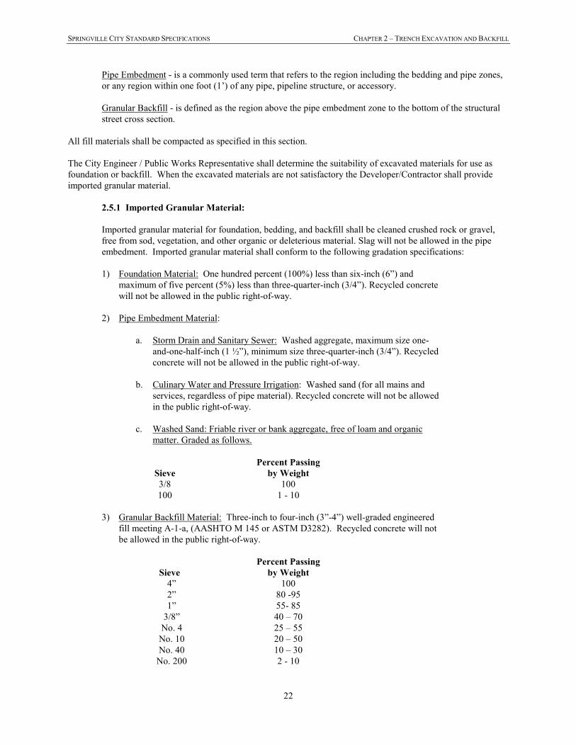
SPRINGVILLE CITY STANDARD SPECIFICATIONS CHAPTER 2 – TRENCH EXCAVATION AND BACKFILL
22
Pipe Embedment - is a commonly used term that refers to the region including the bedding and pipe zones,
or any region within one foot (1’) of any pipe, pipeline structure, or accessory.
Granular Backfill - is defined as the region above the pipe embedment zone to the bottom of the structural
street cross section.
All fill materials shall be compacted as specified in this section.
The City Engineer / Public Works Representative shall determine the suitability of excavated materials for use as
foundation or backfill. When the excavated materials are not satisfactory the Developer/Contractor shall provide
imported granular material.
2.5.1 Imported Granular Material:
Imported granular material for foundation, bedding, and backfill shall be cleaned crushed rock or gravel,
free from sod, vegetation, and other organic or deleterious material. Slag will not be allowed in the pipe
embedment. Imported granular material shall conform to the following gradation specifications:
1) Foundation Material: One hundred percent (100%) less than six-inch (6”) and
maximum of five percent (5%) less than three-quarter-inch (3/4”). Recycled concrete
will not be allowed in the public right-of-way.
2) Pipe Embedment Material:
a. Storm Drain and Sanitary Sewer: Washed aggregate, maximum size one-
and-one-half-inch (1 ½”), minimum size three-quarter-inch (3/4”). Recycled
concrete will not be allowed in the public right-of-way.
b. Culinary Water and Pressure Irrigation: Washed sand (for all mains and
services, regardless of pipe material). Recycled concrete will not be allowed
in the public right-of-way.
c. Washed Sand: Friable river or bank aggregate, free of loam and organic
matter. Graded as follows.
Sieve
Percent Passing
by Weight
3/8 100
100 1 - 10
3) Granular Backfill Material: Three-inch to four-inch (3”-4”) well-graded engineered
fill meeting A-1-a, (AASHTO M 145 or ASTM D3282). Recycled concrete will not
be allowed in the public right-of-way.
Sieve
Percent Passing
by Weight
4” 100
2” 80 -95
1” 55- 85
3/8” 40 – 70
No. 4 25 – 55
No. 10 20 – 50
No. 40 10 – 30
No. 200 2 - 10
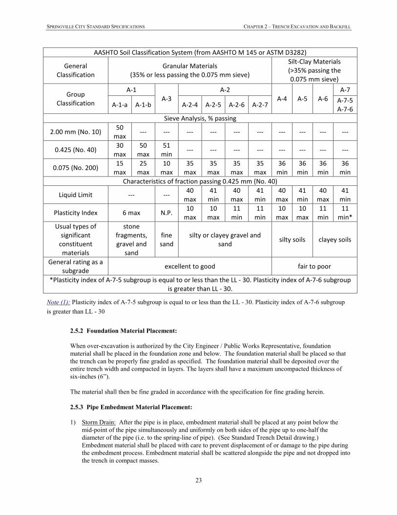
SPRINGVILLE CITY STANDARD SPECIFICATIONS CHAPTER 2 – TRENCH EXCAVATION AND BACKFILL
23
AASHTO Soil Classification System (from AASHTO M 145 or ASTM D3282)
General
Classification
Granular Materials
(35% or less passing the 0.075 mm sieve)
Silt-Clay Materials
(>35% passing the
0.075 mm sieve)
Group
Classification
A-1
A-3
A-2
A-4 A-5 A-6
A-7
A-1-a A-1-b A-2-4 A-2-5 A-2-6 A-2-7 A-7-5
A-7-6
Sieve Analysis, % passing
2.00 mm (No. 10) 50
max --- --- --- --- --- --- --- --- --- ---
0.425 (No. 40) 30
max
50
max
51
min --- --- --- --- --- --- --- ---
0.075 (No. 200) 15
max
25
max
10
max
35
max
35
max
35
max
35
max
36
min
36
min
36
min
36
min
Characteristics of fraction passing 0.425 mm (No. 40)
Liquid Limit --- --- 40
max
41
min
40
max
41
min
40
max
41
min
40
max
41
min
Plasticity Index 6 max N.P. 10
max
10
max
11
min
11
min
10
max
10
max
11
min
11
min*
Usual types of
significant
constituent
materials
stone
fragments,
gravel and
sand
fine
sand
silty or clayey gravel and
sand silty soils clayey soils
General rating as a
subgrade excellent to good fair to poor
*Plasticity index of A-7-5 subgroup is equal to or less than the LL - 30. Plasticity index of A-7-6 subgroup
is greater than LL - 30.
Note (1): Plasticity index of A-7-5 subgroup is equal to or less than the LL - 30. Plasticity index of A-7-6 subgroup
is greater than LL - 30
2.5.2 Foundation Material Placement:
When over-excavation is authorized by the City Engineer / Public Works Representative, foundation
material shall be placed in the foundation zone and below. The foundation material shall be placed so that
the trench can be properly fine graded as specified. The foundation material shall be deposited over the
entire trench width and compacted in layers. The layers shall have a maximum uncompacted thickness of
six-inches (6”).
The material shall then be fine graded in accordance with the specification for fine grading herein.
2.5.3 Pipe Embedment Material Placement:
1) Storm Drain: After the pipe is in place, embedment material shall be placed at any point below the
mid-point of the pipe simultaneously and uniformly on both sides of the pipe up to one-half the
diameter of the pipe (i.e. to the spring-line of pipe). (See Standard Trench Detail drawing.)
Embedment material shall be placed with care to prevent displacement of or damage to the pipe during
the embedment process. Embedment material shall be scattered alongside the pipe and not dropped into
the trench in compact masses.
SPRINGVILLE CITY STANDARD SPECIFICATIONS CHAPTER 2 – TRENCH EXCAVATION AND BACKFILL
24
2) Sanitary Sewer: After the pipe is in place, embedment material shall be placed at any point below the
mid-point of the pipe simultaneously and uniformly on both sides of the pipe up to one-half the
diameter of the pipe (i.e. to the spring-line of pipe). Pipe shall then be “haunched” for the entire length
of the pipe prior to placement of remaining embedment material. (See Standard Trench Detail
drawing.) Embedment material shall be placed with care to prevent displacement of or damage to the
pipe during the embedment process. Embedment material shall be scattered alongside the pipe and not
dropped into the trench in compact masses.
3) Culinary Water and Pressure Irrigation: After the pipe is in place, the embedment material shall be
deposited over the entire trench width and shall have a maximum un-compacted thickness of eight-
inches (8”) per lift. Each lift shall then be compacted to the specified density requirement before
placement of additional lift(s). (See Standard Trench Detail drawing.) Embedment material shall be
placed with care to prevent displacement of or damage to the pipe during the embedment process.
Embedment material shall be scattered alongside the pipe and not dropped into the trench in compact
masses.
2.5.4 Granular Backfill Material Placement:
Granular backfill shall be from top of embedment material to the level shown on the Drawings. The backfill
material shall be deposited over the entire trench width and shall have a maximum un-compacted thickness
of twelve-inches (12”) per lift. Each lift shall then be compacted to the specified density requirement before
placement of additional lift(s). (See Standard Trench Detail drawing.) Backfill shall be compacted by
means of sheepsfoot rollers, pneumatic tire rollers, vibrating rollers, or mechanical tampers.
2.5.5 Compaction:
Within the public right-of-way the in-place density shall be a minimum of 95% of laboratory standard the
maximum dry density as determined by AASHTO T-180 (Modified Proctor). In other areas the in-place
density shall be a minimum of ninety percent (90%) of the maximum dry density as determined by
AASHTO T-180 (Modified Proctor).
If the required relative density is not attained, Developer/Contractor will be required to make any
adjustments in compaction equipment, thickness of layers, moisture content and compactive effort
necessary to attain the specified minimum relative density.
2.6 PRIVATE PROPERTY ACCESS AND RESTORATION
At road crossings or where existing driveways occur on a road, the Developer/Contractor shall make provisions for
trench crossings either by means of backfill, tunnels, or temporary bridges.
Any disturbance to property caused by the Developer/Contractor’s activity shall be restored to the satisfaction of the
owner of the property. If necessary, shrubs, fences, or other objects shall be removed carefully. If work must occur
on a lawn, the lawn shall be cut to a width of two feet (2’) wider than the intended work area (one foot (1’) on each
side). The lawn sod shall be stacked separately from and shall not be mixed with other excavated material.
After the sod is removed, if excavation is necessary, the topsoil shall be removed to a depth of twelve inches (12”),
or the actual depth of the topsoil, whichever is less. The topsoil shall be stored separately from and shall not be
mixed with other excavated material.
Following completion of the backfilling and the compaction of the trench, the Developer/Contractor shall replace
topsoil, lawn sod, shrubs, fences, and other items that may have been removed from within the work area and shall
clean up and remove any rocks, dirt or any other debris that remain from the construction work. The
Developer/Contractor shall obtain a release from the property owner stating that the repairs have been made to the
SPRINGVILLE CITY STANDARD SPECIFICATIONS CHAPTER 2 – TRENCH EXCAVATION AND BACKFILL
25
satisfaction of the Owner. A copy of said release shall be delivered to the City Engineer / Public Works
Representative.
2.7 RESTORATION OF CONSTRUCTION SITE
During the progress of the Work, the Developer/Contractor shall clean up all construction debris, excess excavation,
and excess materials, and shall restore all fences, irrigation structures, ditches, culverts, and similar items. The
Developer/Contractor shall stockpile the excavated trench material so as to do the least damage to adjacent grassed
areas, or fences, regardless of whether these are on private property or public rights-of-way. All excavated materials
shall be removed from grassed and planted areas and these surfaces shall be left in a conditions equivalent to their
original surface and free from all rocks, gravel, boulders, or other foreign materials.
2.8 DEVELOPER/CONTRACTOR'S RESPONSIBILITY
The Developer/Contractor will be responsible to see that the backfilling and compaction are properly and adequately
done. Settlement of trenches within a period of one (1) years after final acceptance of the project shall be considered
incontrovertible evidence of inadequate compaction, and the Developer/Contractor shall be responsible for
correcting the condition in accordance with the provisions of these Specifications. This includes the replacement of
sidewalk, curb and gutter, and other surface improvements.
SPRINGVILLE CITY STANDARD SPECIFICATIONS CHAPTER 3 – PRESSURE IRRIGATION
26
CHAPTER 3 - PRESSURE IRRIGATION
3.1 GENERAL
This division covers furnishing and installing pressure pipe as shown on the Drawings or established in the field, and
all flushing, testing, repairing, as required to ensure adequate and safe operation of the water system.
All utilities must have a minimum cover of thirty inches (30”) from finished grade of pavement.
3.2 PVC PIPE
3.2.1 Materials:
Pipe for the transmission and distribution of water shall be manufactured in accordance with AWWA C900
standards latest revision, "AWWA Standard for Polyvinyl Chloride (PVC) Pressure Pipe, 4-inch through
12-inch, for Water:" PVC pipe fourteen inches (14”) and larger shall be manufactured in accordance with
AWWA C905 standards latest revision, "AWWA Standard for Polyvinyl Chloride (PVC) Water
Transmission Pipe, Nominal Diameters 14-inch through 36-inch." All PVC pipe four-inch (4”) and larger
shall be dimension ratio (DR) 18 with a working pressure of 150 psi. The PVC pipe shall have a cast-iron-
pipe-equivalent outside diameter. Pressure Irrigation pipe shall be purple in color for easy identification.
3.2.2 Joints:
Joints shall be the push-on rubber-gasket type. Lubrication shall be water soluble, non-supporting of
bacteria growth, and have no deteriorating effect on the PVC pipe or rubber gaskets.
3.2.3 Fittings:
All fittings to be used with the PVC pipe shall be the same as fittings for ductile iron pipe and shall conform
to the provisions of ANSI/AWWA C110/A21.10-82 or C153/A21.53-58. Pipe fittings shall be Mechanical-
Joint-(MJ)-type with retainer gland (Megalug or equivalent) unless otherwise specified by the City Engineer
/ Public Works Representative. All fittings shall be greased with FM grease and encased in 8 mil protective
plastic.
A megalug-type retainer gland system shall be used on all mechanical joints and shall meet Uni-B-13 for
PVC and be UL/FM approved through twelve (12) inch diameter for both ductile iron and PVC pipe. The
restraint mechanism shall consist of individually activated gripping surfaces to maximize restraint
capability. Twist-off nuts, sized the same as the tee-head bolts, and shall be used to ensure proper activating
of restraining devices. The gland shall be manufactured of ductile iron conforming to ASTM A-536-80. The
retainer-gland shall have a pressure rating equal to that of the pipe on which it is used (through fourteen
inches) with a minimum safety factor of 2:1. Gland shall be Megalug by EBAA Iron, Inc. or approved
equal. The type and model of retainer and amount for each connector is shown on standard drawings.
3.2.4 Detectable Caution Tape:
All pipe shall include a three-inch (3”) wide detectable caution tape installed in the pipeline trench
approximately twelve inches (12”) above the top of pipeline. This tape shall be prepared with white or
black printing on a purple field, color Panatone 512C, having the words:
CAUTION: NONPOTABLE WATER - DO NOT DRINK.
3.2.5 Tracer Wire:
All pipes shall include a 12 gauge solid THHN tracer wire installed according to NESC standards. The
tracer wire shall be installed and secured to the top center of the pipe. The tracer wire shall be installed on
SPRINGVILLE CITY STANDARD SPECIFICATIONS CHAPTER 3 – PRESSURE IRRIGATION
27
all service lines per the standard drawings. The tracer wire shall also be brought up along the outside of,
and then through, the top of the valve box through a drilled hole (as specified on the standard drawings),
unless directed otherwise by the City Engineer or his designee. All connections shall be made with
waterproof grease nut connectors to help ensure continuity. A continuity test shall be conducted by the City
to verify the integrity of the tracer wire installed by the Contractor. It is the responsibility of the Contractor
to ensure that the continuity test is performed by the City prior to any paving operations. Failures in the
continuity are the responsibility of the Contractor and shall be repaired by the Contractor and verified by the
City prior to any paving operations.
3.3 RESILIENT SEATED GATE VALVE
Valves in sizes 4" through 10" shall be of the iron body, non-rising bronze stem, resilient seated type, manufactured
to equal or exceed all applicable AWWA standards latest revision and all specific requirements outlined in these
specifications.
All gate valves shall be WATEROUS Series 2500 or MUELLER A-2361.
3.4 BUTTERFLY VALVE
Valves in sizes 12” and larger shall be butterfly valves manufactured to equal or exceed all applicable AWWA
standards latest revision and all specific requirements outlined in these specifications.
All butterfly valves shall be M&H 4500 or MUELLER LINESEAL III or approved equal
3.5 VALVE BOXES
Valves and valve boxes shall be installed as required in these Specifications and Standard Drawings. Valves and
valve boxes shall be set plumb. Valve boxes shall be centered directly over the valve. If the top of the valve nut is
greater than eight (8) feet below finished grade a valve nut extension shall be required. Earth fill shall be carefully
tamped around the valve box to a distance of four (4) feet on all sides of the box, or to the undisturbed trench face if
less than four (4) feet. Valves shall have the interiors cleaned of all foreign matter before installation.
All buried valves shall be installed complete with two-piece, cast iron, 5-1/4-inch shaft valve box with lid. The lid
shall have the words “IRR” or “DRAIN” cast in the metal depending on the application.
3.5.1 Placement of Concrete Collars:
Valve boxes shall be set to the finished grade and contour of the street. Valve boxes shall be protected
during backfilling and compaction of the road base and during the placing or replacing of road surfaces.
Any valve boxes damaged or broken shall be replaced by the Developer/Contractor at its expense. Prior to
paving, the valve box shall be GPS-located by the Developer / Contractor (shot at the center of the valve
box) and set six (6) inches below the finished grade. After paving the asphalt shall be removed, and the
valve box shall be raised to match the grade and slope of the finished road surface.
Road base around the valve box shall be re-compacted, and the concrete collar placed. Valve boxes placed
in asphalt surfacing shall be constructed such that the cast iron ring is one-quarter inch (1/4”) lower than the
pavement. Valve boxes must be cleaned of all debris after setting of collars.
3.6 PIPE INSTALLATION
3.6.1 Cutting:
When required, cutting of pipe shall be done in a neat and workmanlike manner by a method recommended
by the manufacturer. All cuts shall be cut square to the longitudinal axis of the pipe. If needed after cutting,
SPRINGVILLE CITY STANDARD SPECIFICATIONS CHAPTER 3 – PRESSURE IRRIGATION
28
the pipe shall be beveled and filed to prevent gasket damage in joint assembly. All beveled ends of pipe
must be removed before connecting to MJ fittings, in accordance with manufacturer’s recommendations.
3.6.2 Dewatering of Trench:
Where water is encountered in the trench, it shall be removed during pipe-laying operations and until the
ends of the pipe are sealed. See Section 2.3 Control of Groundwater.
3.6.3 Laying of Pipe:
The pipe and pipe coating (where applicable) shall be inspected for defects or UV light damage before
installation. Any defects shall be repaired or the pipe shall be replaced, whichever is deemed necessary by
the City Engineer / Public Works Representative.
All pipe shall be laid and maintained to the required lines with fittings and valves at the required locations,
as shown on the Drawings.
All pipe, fittings, and valves shall be moved carefully, either when lowering from the truck, or when placing
in the trench. Under no circumstances shall materials be dropped or dumped from the truck or into the
trench.
The Developer/Contractor shall take the necessary precautions to ensure that foreign materials do not enter
the pipe. No debris, tools, or other materials shall be placed in the pipe during laying operations. When
laying of pipe is not in progress, the pipe shall be closed with a water tight plug.
Maximum deflections at pipe joints shall not exceed the joint specifications of AWWA C900
(latest revision), or the recommendations of the pipe manufacturer.
Deflections in PVC pipe shall be made by defecting pipe joints and may not be made by longitudinal
bending of the barrel of the pipe.
3.6.4 Joint Restraints:
Concrete thrust blocks shall not be used as a restraining system for waterline mains or laterals without prior
approval of the City Engineer / Public Works Representative. Reaction restraints shall be applied at all
bends and tees, and at all points of reduction or at fittings where changes in pipe diameter occur in
accordance with Standard Pipe Restraint Detail Drawings.
Mechanical restraints for pipes larger than twelve (12) inches in diameter must be designed by a registered
professional engineer and approved by the City Engineer prior to installation.
3.6.5 Thrust Blocking:
With approval of the City Engineer / Public Works Representative thrust blocking may be applied in
addition to required joint restraints at all tees, valves, plugs, caps, and at bends that deflect twenty-two and
one-half (22-1/2°) degrees or more. The fitting shall be encased in a 8 mil protective plastic wrap before the
thrust block is poured. Reaction blocking shall be concrete, having a compressive strength of not less than
three-thousand (3000) psi at twenty-eight (28) days. Blocking shall be placed between undisturbed soil and
the fitting to be anchored. The area of bearing on the pipe and on the ground shall be as shown in the
Drawings. The blocking shall be placed so that the pipe and the fittings will be accessible for repair.
3.6.6 Connections to Existing Irrigation Lines:
SPRINGVILLE CITY STANDARD SPECIFICATIONS CHAPTER 3 – PRESSURE IRRIGATION
29
Information on the Drawings regarding existing pipelines is taken from "record" drawings from the City or
utility company files and may or may not be accurate as to size, type of material, or location of those lines.
The Developer/Contractor will be responsible to determine the proper fittings and materials required, obtain
the City Engineer / Public Works Representative's approval of the planned connection, and perform the
construction in a suitable fashion.
3.6.7 Pipe Embedment:
Refer to Section 2.5.3 Pipe Embedment Material Placement
3.7 PRESSURE IRRIGATION SERVICE CONNECTION
Pressure irrigation service laterals shall be constructed with materials specified and at the locations and limits shown
on the Standard Drawings.
3.7.1 Extent and Locations of Laterals:
New pressure irrigation service laterals shall be installed per the location and limits shown on the utility
location standard drawing. Irrigation service boxes shall be installed in the center of the park strip (where
applicable) or one foot behind sidewalk where park strip does not exist or as approved by the City Engineer
/ Public Works Representative.
Pressure irrigation services shall not have any joints between the saddle at the main and the meter
connection.
Service laterals relocated during construction of new pipelines shall extend from the pressure irrigation
main to the service box if the existing service is in poor condition or of a material other than polyethylene.
Relocated services shall not have any joints between the saddle and the meter.
3.7.2 Connection to Main:
A 24-inch gooseneck shall be formed with the tubing for all connection types. No connections shall be
made to the main within 24” of the end of the pipe joint. On existing services the existing connection to
main will be used unless damaged or leaking.
All connections of services to main lines shall be through a service saddle. All service saddles shall be of a
"Full encirclement design," and shall be I.D. controlled, which design will eliminate the possibility of pipe
crushing due to the over-torquing of the nuts upon installation.
All service saddles shall be manufactured of stainless steel in conformance to AWWA C800, General
Section - 1, Paragraph 1.2 (ASTM B62). All service saddles shall be nylon coated ductile iron service
saddle with dual stainless steel straps, Romac 202NS or equivalent.
Connection to polyethylene service line shall be made using a brass compression by MIPT adapter with Q-
style (quick joint) nut, Ford style C84-44-Q or Mueller style H-15428 only.
3.7.3 Polyethylene Tubing:
Pipe for service laterals shall be a minimum of one inch (1”) diameter. Sizes larger than 1” shall comply
with ASTM Specification B88. Services shall be polyethylene CTS tubing.
Pipe for the transmission of irrigation water from main to utility box shall be purple polyethylene CTS
tube. Polyethylene CTS tube shall be manufactured in accordance with the standard specification for
SPRINGVILLE CITY STANDARD SPECIFICATIONS CHAPTER 3 – PRESSURE IRRIGATION
30
Polyethylene (PEP) plastic tubing as issued by the American Standard for Testing and Materials under
ASTM D 2239 and AWWA C901.
Material designation code: Polyethylene - Purple
PE 3408
Plastic Extrusion Compound: Type III, class C, Grade 34, as defined by ASTM D 2239
Standard pipe dimension ratio CTS (SDR 9) - 160-psi pressure rating.
All tubing for service lines shall be cut and installed in a neat and workmanlike manner by a method
recommended by the manufacturer.
Tubing shall be Cencore HDPE 3408 or equivalent.
3.7.4 Compression Connection:
A rigid liner shall be used inside of all tubing at the compression fitting, regardless of size.
1) The interior surface of the coupling nut, including threads, shall have a baked on, fluorocarbon coating
to reduce assembly friction and prevent the gasket from turning and twisting during tightening. The nut
shall bottom on a cast or machined shoulder on the body when properly assembled. This design will
provide a visual check to assure connection is properly assembled.
2) The sealing gasket shall be of molded synthetic rubber (ASTM D2000) with molded in place bronze
spring (ASTM A134 Alloy #6) to eliminate the possible cold flow of the gasket between the pipe and
fitting. A gripper band of hardened stainless steel (ANSI Type 401) shall be fitted into the gasket.
When the gasket is compressed it will cause the gripper ring to distort the pipe giving the fitting a high
resistance to pull out. The gripper band shall overlap itself to prevent cold flow of the gasket into the
cavity under the band.
3) When compression fittings are used with P.E. Pipe, Stainless Steel pipe stiffeners are required to
eliminate cold flow of plastic pipe.
4) All fittings are to be for CTS Polyethylene pipe.
5) The Minimum pull out load for the fitting when used with PE plastic pipe shall be as follows for each
given size:
SIZE MINIMUM PULL OUT (FT.LBS.)
1” 400
1½” 500
2" 500
MUELLER H-15428 “STRAIGHT SERVICE FITTING” OR FORD C84-XX-Q STYLE “QUICK JOINT
COUPLING” COMPRESSION COUPLINGS AND FITTINGS ARE TO BE USED ON ALL P.E.
PLASTIC PIPE INSTALLATIONS.
3.7.5 Ball Valve Curb Stop:
The valve must maintain a working pressure of 300 PSIG.
All fittings are to be CTS (Copper Tube Size) size, used on CTS Polyethylene pipe. No IPS polyethylene
pipe or fittings are to be used.
SPRINGVILLE CITY STANDARD SPECIFICATIONS CHAPTER 3 – PRESSURE IRRIGATION
31
Ball valve curb stop shall be FORD B43-444-W-Q Style or MUELLER equivalent.
3.7.6 Service Box:
Service box shall be a standard green irrigation box with cover. The size shall be the appropriate size for the
service size and meter as specified and shown on the standard drawings. Service Box shall be installed over
the ball valve and meter as shown on the standard drawings. A sign shall be attached or embossed to or on
the cover indicating as follows: "IRRIGATION." Box shall be Brooks 1419 series utility box with lid
recessed and shall be provided with Waterworks Pentagon Head locking device or equivalent.
3.7.7 PVC Pipe:
Pipe for the transmission of irrigation water from the PVC MIPT adapter to the homeowner’s side of the
valve shall be Schedule 80 PVC pipe threaded nipple, twelve (12) inches long. A threaded end cap will be
installed on the end of the pipe on the homeowner’s side. No joints will be allowed under sidewalks or other
paved surfaces.
3.7.8 Service Pipe Installation:
The polyethylene service pipe shall be installed by use of a "Hole Hog" or other similar device under all
existing paved surfaces. Where subsurface materials or conditions will not permit installation by this
method, open trenching will be permitted with the approval of the City Engineer / Public Works
Representative. Open trenching will be used in new streets not yet paved.
The Developer/Contractor shall install a brass pin, 1/2” in diameter, stamped with the letter “I” in the top
back of curb at the location where the lateral crosses the curb.
3.8 PIPELINE TESTING AND FLUSHING
All newly laid pipes or any valved section thereof shall be subjected to a hydrostatic pressure test. A leakage test
shall be conducted concurrently with the pressure test. All new lines, and extensions there from, shall be flushed
thoroughly before being placed into service. All service line connections must be installed prior to the pressure
test.
3.8.1 Pressure Test:
If the pipe section being tested includes concrete thrust blocking, the concrete shall be allowed at least
twenty-four (24) hours to set before any testing is conducted.
1) Test Pressure Restrictions: Test pressures shall,
a. Be not less than 200 psi.
b. Not exceed the pressure rating of the pipe.
c. Be of at least 2 hour duration.
d. Not exceed twice the rated pressure of the valves or hydrants when the pressure boundary of the
test section includes closed gate valves or hydrants.
e. Not exceed the rated pressure of the valves when the test boundary of the test section includes
closed, resilient-seated gate valves or butterfly valves.
2) Pressurization: Each valved section of pipe shall be filled slowly with water to the specified test
pressure. Pressurization of the pipe shall be based on the elevation of the lowest point of the line or
section under test and corrected to the elevation of the test gage. Pressure shall be applied by means of
SPRINGVILLE CITY STANDARD SPECIFICATIONS CHAPTER 3 – PRESSURE IRRIGATION
32
a pump connected to the pipe in a manner satisfactory to the City Engineer / Public Works
Representative.
3) Air Removal: Before applying the specified test pressure, air shall be expelled completely from the
pipe, valves, and hydrants. If permanent air vents are not located at all high points, the
Developer/Contractor shall install corporation cocks at such points so that the air can be expelled as the
line is filled with water. After all the air has been expelled, the corporation cocks shall be closed and
the test pressure applied. At the conclusion of the pressure test, the corporation cocks shall be removed
and plugged.
4) Examination: All exposed pipe, fittings, valves, hydrants, and joints shall be examined carefully during
the test. Any damaged or defective pipe, fittings, valves, or hydrants that are discovered during the
pressure test shall be repaired or replaced with sound materials and the test shall be repeated. Repairs
or replacements to the pipeline and subsequent pressure testing shall be repeated as necessary for the
pipeline to pass the pressure test.
5) Length of Pipeline: The maximum length of pipeline tested at one time shall be 1,000 feet.
3.8.2 Leakage Test:
A leakage test shall be conducted concurrently with the pressure test.
1) Leakage defined: Leakage shall be defined as the quantity of water that must be supplied into the
newly laid pipe, or any valved section thereof, to maintain the specified test pressure after the air in the
pipeline has been expelled and the pipe has been filled with water.
2) Allowable leakage: No pipe installation will be accepted if the leakage is greater than the pipeline
manufacture’s specifications, or that determined by the following formula, whichever is less:
L = SD(P)0.5
133,200
In which L is the allowable leakage, in gallons per hour; S is the length of pipeline tested in feet; D is
the nominal diameter of the pipe, in inches; and P is the average test pressure (gage) during the leakage
test, in pounds per square inch. See Table 1.
a. Allowable leakage at various pressures is shown in Table 1.
b. When testing against closed metal-seated valves, an additional leakage per closed valve of 0.0078
gal/hr/in. of nominal valve size shall be allowed.
c. When hydrants are in the test section, the test shall be made against the closed hydrant.
SPRINGVILLE CITY STANDARD SPECIFICATIONS CHAPTER 3 – PRESSURE IRRIGATION
33
TABLE 1
Allowable Leakage per 1000 ft of Pipeline - gph
Average
Test Pressure
Nominal Pipe Diameter—in.
psi (Bar)
3 4 6 8 10 12 14 16 18 20 24 30 36 42 48 54
450 (31) 400 (28) 350 (24) 300 (21) 275 (19) 250 (17) 225 (16) 200 (14) 175 (12) 150 (10) 125 ( 9) 100 ( 7)
0.48 0.45 0.42 0.39 0.37 0.36 0.34 0.32 0.30 0.28 0.25 0.23
0.64 0.60 0.56 0.52 0.50 0.47 0.45 0.43 0.40 0.37 0.34 0.30
0.95 0.90 0.84 0.78 0.75 0.71 0.68 0.64 0.59 0.55 0.50 0.45
1.27 1.20 1.12 1.04 1.00 0.95 0.90 0.85 0.80 0.74 0.67 0.60
1.59 1.50 1.40 1.30 1.24 1.19 1.13 1.06 0.99 0.92 0.84 0.75
1.91 1.80 1.69 1.56 1.49 1.42 1.35 1.28 1.19 1.10 1.01 0.90
2.23 2.10 1.97 1.82 1.74 1.66 1.58 1.48 1.39 1.29 1.18 1.05
2.55 2.40 2.25 2.08 1.99 1.90 1.80 1.70 1.59 1.47 1.34 1.20
2.87 2.70 2.53 2.34 2.24 2.14 2.03 1.91 1.79 1.66 1.51 1.35
3.18 3.00 2.81 2.60 2.49 2.37 2.25 2.12 1.98 1.84 1.68 1.50
3.82 3.60 3.37 3.12 2.99 2.85 2.70 2.55 2.38 2.21 2.01 1.80
4.78 4.50 4.21 3.90 3.73 3.56 3.38 3.19 2.98 2.76 2.52 2.25
5.73 5.41 5.06 4.68 4.48 4.27 4.05 3.82 3.58 3.31 3.02 2.70
6.69 6.31 5.90 5.46 5.23 4.99 4.73 4.46 4.17 3.86 3.53 3.15
7.64 7.21 6.74 6.24 5.98 5.70 5.41 5.09 4.77 4.41 4.03 3.60
8.60 8.11 7.58 7.02 6.72 6.41 6.03 5.73 5.36 4.97 4.53 4.05
*If the pipeline under test contains sections of various diameters, the allowable leakage will be the sum of the computed leakage for each size.
**To obtain leakage in liters/hour, multiply the values in the table by 3.785.
3) Examination: All exposed pipe, fittings, valves, hydrants, and joints shall be examined carefully during
the test. Any damaged or defective pipe, fittings, valves, or hydrants that are discovered during the
leakage test shall be repaired or replaced with sound materials and the test shall be repeated. Repairs
or replacements to the pipeline and subsequent leakage testing shall be performed as necessary for the
pipeline to pass the leakage test.
3.8.3 Acceptance of Testing:
Acceptance of testing shall be determined on the basis of allowable leakage. If any test of pipe laid
discloses leakage greater than specified, the Developer/Contractor shall, at its own expense, locate and
repair the defective material until the leakage is within the specified allowance.
All visible leaks are to be repaired regardless of the amount of leakage.
3.8.4 Flushing:
Flushing shall be accomplished through temporary flushing valves, or end of line blow-off assemblies at a
minimum flushing velocity of two and one-half feet per second (2.5 fps). Flow volumes to produce this
velocity are shown in the following chart:
FLOW RATE AND OPENINGS TO FLUSH PIPELINES
(40 psi Residual Pressure)
Pipe Size (inches)
Flow Required to Produce
2.5 fps velocity (gpm)
2 26
4 100
6 220
8 390
10 610
12 880
14 1,200
16 1,565
18 1,980
20 2,450
24 3,525
30 5,507
42 10,800
48 14,100
SPRINGVILLE CITY STANDARD SPECIFICATIONS CHAPTER 3 – PRESSURE IRRIGATION
34
3.9 AIR RELEASE and VACUUM RELIEF VALVE
Air release and vacuum relief valves shall fulfill functions of air release (permit escape of air accumulated in line at
high point of elevation while line is under pressure) and vacuum relief (allow air to enter the pipe and prevent its
potential collapse due to the formation of a vacuum condition caused by rapid withdrawal of water) . Air and vacuum
relief valves shall be placed at high points or uphill end points in the system. The need for air relief valves should be
minimized through the engineering design of the line.
Air release and vacuum relief valves shall be single-body, standard combination valves rated for a minimum working
pressure of 150 psi, unless otherwise indicated. (APCO Model 145C or approved equal as indicated on Standard
Drawings). Bodies shall be of high strength cast iron. The float, seat, and all moving parts shall be constructed of
Type 316 stainless steel. Seat washers and gaskets shall be of a material insuring water tightness with a minimum of
maintenance. The valve exterior shall be painted with shop-applied primer suitable for contact with potable water.
The connection to the main for the air release and vacuum relief valve shall be service clamp, Ford FS202 or
approved equal. Tapping the main through the service clamp will be accomplished with standard tapping equipment
before the system is put into service. Typical small distribution mains (4” to 12”) shall have the typical 2-inch
combination air-vacuum valves per the Standard Drawings. Larger water main pipelines shall have valves which are
engineered and sized to compensate for the size of pipe and the length of run.
Valves shall be installed in a 5-foot diameter precast manhole base with a standard manhole frame and lid (D&L
1180 or approved equal) per Standard Drawing. The manhole lid shall read “WATER’ or “PRESSURIZED
IRRIGATION” as appropriate. Set the manhole base and lid plumb and as detailed. Center the manhole over valve.
For culinary water use, the valve shall be plumbed out of the vault and behind the closest curb and gutter to vent.
The air vent stand pipe shall be centered in the park strip or as directed by the City Engineer.
3.10 PRESSURE IRRIGATION DRAINS
When system drains are necessary to be installed on extensions of the pressure irrigation system they shall be
constructed as a system drain to a curb inlet box or a storm drain manhole. As an alternative, the system drain may
enter directly to a storm drainage pipe if approved by the City Engineer or his authorized representative. The drain
shall be constructed as shown on the Standard Drawings. The materials used shall meet the requirements of Division
3, Pressure Pipe Pressure Irrigation. The connection to the box or pipe shall be by coring a hole and grouting the
drainpipe in. A non-shrink grout shall be used.
When a section of pressure irrigation pipeline has to be laid such that there is a belly in it then a local drain sump
will need to be constructed. The drain shall be constructed as shown on the Standard Drawings.
SPRINGVILLE CITY STANDARD SPECIFICATIONS CHAPTER 4 – CULINARY WATER
35
CHAPTER 4 - CULINARY WATER
4.1 GENERAL
This Division covers furnishing and installing pressure pipe to the lines and grades shown on the drawings and/or
established in the field, and all flushing, testing, repairing, as required to ensure adequate and safe operation of the
water system.
Ductile iron pipe shall be used in all areas east of 400 West unless otherwise specified by the City Engineer. PVC
pipe will be used in all areas west of 400 West
4.2 DUCTILE IRON PIPE
4.2.1 Materials:
Ductile iron pipe shall conform to all requirements of ANSI/AWWA C151/A21.51. Minimum pressure
class of pipes of 12-inch diameter and smaller shall be pressure Class 350. Minimum pressure Class will be
250 for pipes larger than 12-inch diameter. If thickness class pipe is used, pipes of diameters from 4 inches
through 10 inches shall be minimum Class 51 and pipe from 12-inch diameter and larger shall be minimum
Class 50. All pipe shall be gauged pipe.
4.2.2 Joints:
1) Mechanical Joints: All mechanical joint fittings with accessories shall meet all applicable requirements
of ANSI/AWWA C110/A21.10 and ANSI/AWWA C111/A21.11 (current revisions). All gasket
surfaces shall be smooth and free from imperfections. Gaskets shall conform to tests in accordance
with specifications and shall be less than one year old. All buried fittings having steel bolts shall be
coated with food-grade grease and wrapped with polyethylene.
2) Push-on Joints: Joints shall be push on rubber gasket type. Lubrication shall be water soluble, non-
toxic, non-objectionable in taste and odor imparted to the water, non-supporting of bacteria growth, and
have no deteriorating effect on the pipe or rubber gaskets. All push-on joints shall meet the
requirements of ANSI/AWWA C111/A21.11. Gaskets shall be free from defects and not over one year
old.
Lubricants shall be non-toxic and have no deteriorating effects on gasket materials. It shall not impart
taste to water in a pipe. It shall conform in every way to ANSI 21.1
3) Flanged Joints: Flange joints on fittings shall meet the requirements of ANSI/AWWA C110/A21.10 or
ANSI B16.1. Flanges on pipe shall meet the requirements of AWWA C115. Flanged joints shall be
bolted firmly with machine, stud or cap bolts of proper size. Flange maybe cast integrally with the pipe
or may be screwed on threaded pipe. Flanges shall be faced and drilled and of proper dimensions for
size and pressure required. Bolts and nuts, unless otherwise specified, shall be made of the best quality
refined iron or metal steel and have clean, well-fitting threads. Bolts will be provided with standard
hexagonal nuts and standard hexagonal heads. Bolts shall be of the diameter required for each flange
and when installed shall be of length so that no more than 3/8-inch nor less than 1/8-inch extends past
face of nut. All buried fittings having steel bolts shall be coated with food-grade grease and wrapped
with polyethylene.
4.2.3 Coatings and Linings for Ductile Iron Pipe:
All exterior surfaces of pipe and fittings shall be coated with hot coal tar approximately 1 mil thick. All
interior surfaces shall be cement mortar lined with a standard thickness according to ANSI/AWWA
C104/A21.4-80.
SPRINGVILLE CITY STANDARD SPECIFICATIONS CHAPTER 4 – CULINARY WATER
36
4.2.4 Corrosion Protection and Soil Tests:
When the City Engineer / Public Works Representative determines that a potential for corrosive conditions
exists such as poor drainage or reactive soils, PVC pipe shall be used rather than ductile iron.
4.2.5 Fittings:
All fittings to be used with the ductile iron pipe shall conform to the provisions of ANSI/AWWA
C110/A21.10-82 or C153/A21.53-58. Pipe fittings shall be Mechanical-Joint-(MJ)-type with retainer gland
(Megalug or equivalent) approved by the manufacturer for the specific pipe material unless otherwise
specified by the City Engineer / Public Works Representative. All fittings shall be greased with FM NLGI
2 grease and encased in 8 mil protective plastic.
A megalug-type retainer gland system shall be used on all mechanical joints and shall meet Uni-B-13 for
PVC and be UL/FM approved through twelve (12) inch diameter for both ductile iron and PVC pipe. The
restraint mechanism shall consist of individually activated gripping surfaces to maximize restraint
capability. Twist-off nuts, sized the same as the tee-head bolts, and shall be used to ensure proper activating
of restraining devices. The gland shall be manufactured of ductile iron conforming to ASTM A-536-80. The
retainer-gland shall have a pressure rating equal to that of the pipe on which it is used (through fourteen
inches) with a minimum safety factor of 2:1. Gland shall be Megalug by EBAA Iron, Inc. or approved
equal. The type and model of retainer and amount for each connector is shown on standard drawings.
4.2.6 Detectable Caution Tape:
All pipe shall include a three-inch (3”) wide detectable caution tape installed in the pipeline trench
approximately twelve inches (12”) above the top of pipeline. Caution tape shall be furnished with white or
black printing on a blue colored field having the words:
CAUTION: POTABLE WATER - BELOW.
4.2.7 Tracer Wire:
All pipes shall include a 12 gauge solid THHN tracer wire installed according to NESC standards. The
tracer wire shall be installed and secured to the top center of the pipe. The tracer wire shall be brought up
and connected to a fire hydrant flange bolt at each hydrant for pipe line location. The tracer wire shall also
be installed on all service lines per the standard drawings. The tracer wire shall also be brought up along
the outside of, and then through, the top of the valve box through a drilled hole (as specified on the standard
drawings), unless directed otherwise by the City Engineer or his designee. All connections shall be made
with waterproof grease nut connectors to help ensure continuity. A continuity test shall be conducted by the
City to verify the integrity of the tracer wire installed by the Contractor. It is the responsibility of the
Contractor to ensure that the continuity test is performed by the City prior to any paving operations.
Failures in the continuity are the responsibility of the Contractor and shall be repaired by the Contractor and
verified by the City prior to any paving operations.
4.3 PVC PIPE
4.3.1 Materials:
Pipe for the transmission and distribution of water shall be manufactured in accordance with AWWA C900
standards latest revision, "AWWA Standard for Polyvinyl Chloride (PVC) Pressure Pipe, 4-inch through
12-inch, for Water:" PVC pipe fourteen inches (14”) and larger shall be manufactured in accordance with
AWWA C905 standards latest revision, "AWWA Standard for Polyvinyl Chloride (PVC) Water
Transmission Pipe, Nominal Diameters 14-inch through 36-inch." All PVC pipe four-inch (4”) and larger
SPRINGVILLE CITY STANDARD SPECIFICATIONS CHAPTER 4 – CULINARY WATER
37
shall be dimension ratio (DR) 18 with a working pressure of 150 psi. The PVC pipe shall have a cast-iron-
pipe-equivalent outside diameter.
4.3.2 Joints:
1) Mechanical Joints: All mechanical joint fittings with accessories shall meet all applicable requirements
of ANSI/AWWA C110/A21.10 and ANSI/AWWA C111/A21.11 (current revisions). All gasket
surfaces shall be smooth and free from imperfections. Gaskets shall conform to tests in accordance
with specifications and shall be less than one year old. All buried fittings having steel bolts shall be
coated with food-grade grease and wrapped with polyethylene.
2) Push-on Joints: Joints shall be push on rubber gasket type. Lubrication shall be water soluble, non-
toxic, non-objectionable in taste and odor imparted to the water, non-supporting of bacteria growth, and
have no deteriorating effect on the pipe or rubber gaskets. All push-on joints shall meet the
requirements of ANSI/AWWA C111/A21.11. Gaskets shall be free from defects and not over one year
old.
Lubricants shall be non-toxic and have no deteriorating effects on gasket materials. It shall not impart
taste to water in a pipe. It shall conform in every way to ANSI 21.1
3) Flanged Joints: Flange joints on fittings shall meet the requirements of ANSI/AWWA C110/A21.10 or
ANSI B16.1. Flanges on pipe shall meet the requirements of AWWA C115. Flanged joints shall be
bolted firmly with machine, stud or cap bolts of proper size. Flange maybe cast integrally with the pipe
or may be screwed on threaded pipe. Flanges shall be faced and drilled and of proper dimensions for
size and pressure required. Bolts and nuts, unless otherwise specified, shall be made of the best quality
refined iron or metal steel and have clean, well-fitting threads. Bolts will be provided with standard
hexagonal nuts and standard hexagonal heads. Bolts shall be of the diameter required for each flange
and when installed shall be of length so that no more than 3/8-inch nor less than 1/8-inch extends past
face of nut. All buried fittings having steel bolts shall be coated with food-grade grease and wrapped
with polyethylene.
4.3.3 Fittings:
All fittings to be used with the PVC pipe shall conform to the provisions of ANSI/AWWA C110/A21.10-82
or C153/A21.53-58. Pipe fittings shall be Mechanical-Joint-(MJ)-type with retainer gland (Megalug or
equivalent) approved by the manufacturer for the specific pipe material unless otherwise specified by the
City Engineer / Public Works Representative. All fittings shall be greased with FM NLGI 2 grease and
encased in 8 mil protective plastic.
A megalug-type retainer gland system shall be used on all mechanical joints and shall meet Uni-B-13 for
PVC and be UL/FM approved through twelve (12) inch diameter for both ductile iron and PVC pipe. The
restraint mechanism shall consist of individually activated gripping surfaces to maximize restraint
capability. Twist-off nuts, sized the same as the tee-head bolts, and shall be used to ensure proper activating
of restraining devices. The gland shall be manufactured of ductile iron conforming to ASTM A-536-80. The
retainer-gland shall have a pressure rating equal to that of the pipe on which it is used (through fourteen
inches) with a minimum safety factor of 2:1. Gland shall be Megalug by EBAA Iron, Inc. or approved
equal. The type and model of retainer and amount for each connector is shown on standard drawings.
4.3.4 Detectable Caution Tape:
All pipe shall include a three-inch (3”) detectable caution tape installed in the pipeline trench approximately
twelve inches (12”) below the ground surface. Caution tape shall be furnished with white or black printing
on a colored field having the words:
CAUTION: POTABLE WATER - BELOW.
SPRINGVILLE CITY STANDARD SPECIFICATIONS CHAPTER 4 – CULINARY WATER
38
4.3.5 Tracer Wire:
All pipes shall include a 12 gauge solid THHN tracer wire installed according to NESC standards. The
tracer wire shall be installed and secured to the top center of the pipe. The tracer wire shall be brought up
and connected to a fire hydrant flange bolt at each hydrant for pipe line location. The tracer wire shall also
be installed on all service lines per the standard drawings. The tracer wire shall also be brought up along
the outside of, and then through, the top of the valve box through a drilled hole (as specified on the standard
drawings), unless directed otherwise by the City Engineer or his designee. All connections shall be made
with waterproof grease nut connectors to help ensure continuity. A continuity test shall be conducted by the
City to verify the integrity of the tracer wire installed by the Contractor. It is the responsibility of the
Contractor to ensure that the continuity test is performed by the City prior to any paving operations.
Failures in the continuity are the responsibility of the Contractor and shall be repaired by the Contractor and
verified by the City prior to any paving operations.
4.4 PIPE INSTALLATION
4.4.1 Cutting:
When required, cutting of pipe shall be done in a neat and workmanlike manner by a method recommended
by the manufacturer. All cuts shall be cut square to the longitudinal axis of the pipe. If needed after cutting,
the pipe shall be beveled and filed to prevent gasket damage in joint assembly. All beveled ends of pipe
must be removed before connecting to MJ fittings, in accordance with manufacturer’s recommendations.
4.4.2 Dewatering of Trench:
Where water is encountered in the trench, it shall be removed during pipe-laying operations and until the
ends of the pipe are sealed. See Section 2.3 Control of Groundwater.
4.4.3 Laying of Pipe:
The pipe and pipe coating (where applicable) shall be inspected for defects or UV light damage before
installation. Any defects shall be repaired or the pipe shall be replaced, whichever is deemed necessary by
the City Engineer / Public Works Representative.
All pipe shall be laid and maintained to the required lines with fittings and valves at the required locations,
as shown on the Drawings.
All pipe, fittings, and valves shall be moved carefully, either when lowering from the truck, or when placing
in the trench. Under no circumstances shall materials be dropped or dumped from the truck or into the
trench.
The Developer/Contractor shall take the necessary precautions to ensure that foreign materials do not enter
the pipe. No debris, tools, or other materials shall be placed in the pipe during laying operations. When
laying of pipe is not in progress, the pipe shall be closed with a water tight plug.
Maximum deflections at pipe joints shall not exceed the joint specifications of AWWA C900
(latest revision), or the recommendations of the pipe manufacturer.
Deflections in PVC pipe shall be made by defecting pipe joints and may not be made by longitudinal
bending of the barrel of the pipe.
4.4.4 Joint Restraints:
SPRINGVILLE CITY STANDARD SPECIFICATIONS CHAPTER 4 – CULINARY WATER
39
Concrete thrust blocks shall not be used as a restraining system for waterline mains or laterals without prior
approval of the City Engineer / Public Works Representative. Reaction restraints shall be applied at all
bends and tees, and at all points of reduction or at fittings where changes in pipe diameter occur in
accordance with Standard Pipe Restraint Detail Drawings.
Mechanical restraints for pipes larger than twelve (12) inches in diameter must be designed by a registered
professional engineer and approved by the City Engineer prior to installation.
4.4.5 Thrust Blocking:
With approval of the City Engineer / Public Works Representative thrust blocking may be applied in
addition to required joint restraints at all tees, valves, plugs, caps, and at bends that deflect twenty-two and
one-half (22-1/2°) degrees or more. The fitting shall be encased in a 8 mil protective plastic wrap before the
thrust block is poured. Reaction blocking shall be concrete, having a compressive strength of not less than
three-thousand (3000) psi at twenty-eight (28) days. Blocking shall be placed between undisturbed soil and
the fitting to be anchored. The area of bearing on the pipe and on the ground shall be as shown in the
Drawings. The blocking shall be placed so that the pipe and the fittings will be accessible for repair.
4.4.6 Connections to Existing Water Lines:
Information on the Drawings regarding existing pipelines is taken from "record" drawings from the City or
utility company files and may or may not be accurate as to size, type of material, or location of those lines.
The Developer/Contractor will be responsible to determine the proper fittings and materials required, obtain
the City Engineer / Public Works Representative's approval of the planned connection, and perform the
construction in a suitable fashion.
4.4.7 Pipe Embedment:
Refer to Section 2.5.3 Pipe Embedment Material Placement
4.5 WATER SERVICE LATERALS
Water service laterals shall be constructed with materials specified and at the locations shown on the Standard
Drawings or at the actual location established during construction.
Pipe for water service laterals shall be a minimum of 1” in diameter. Sizes larger than 1” shall comply with ASTM
Specification B88. Services shall be either Type K-soft copper tubing or polyethylene CTS tubing.
Polyethylene CTS tube shall be manufactured in accordance with the standard specification for Polyethylene (PEP)
plastic tubing as issued by the American Standard for Testing and Materials under ASTM D 2239 and AWWA
C901. Standard pipe dimension ratio CTS (SDR 9) - 160-psi pressure rating. Tubing shall be Cencore HDPE 3408
or equivalent.
All tubing for service lines shall be cut and installed in a neat and workmanlike manner by a method recommended
by the manufacturer.
4.5.1 Extent and Locations of Laterals:
New water service laterals shall be installed at the centerline of the lot. Meter cans shall be installed in the
center of the park strip (where applicable) or one foot behind sidewalk where park strip does not exist or as
approved by the City Engineer / Public Works Representative.
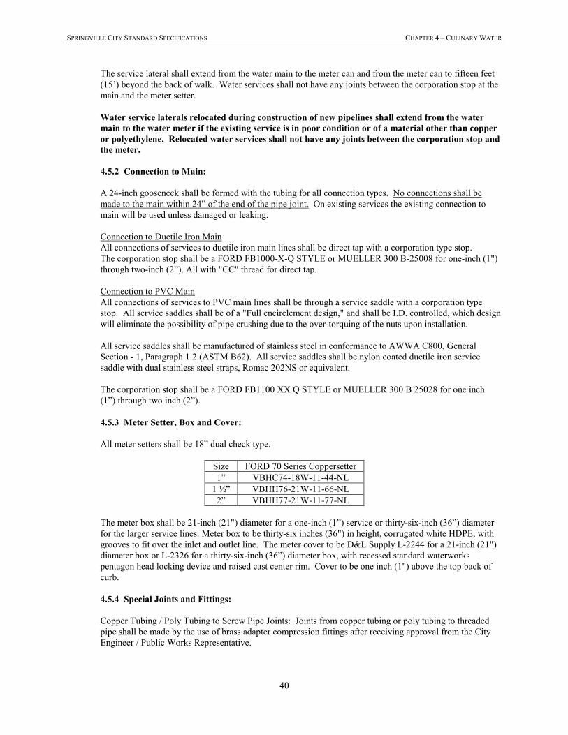
SPRINGVILLE CITY STANDARD SPECIFICATIONS CHAPTER 4 – CULINARY WATER
40
The service lateral shall extend from the water main to the meter can and from the meter can to fifteen feet
(15’) beyond the back of walk. Water services shall not have any joints between the corporation stop at the
main and the meter setter.
Water service laterals relocated during construction of new pipelines shall extend from the water
main to the water meter if the existing service is in poor condition or of a material other than copper
or polyethylene. Relocated water services shall not have any joints between the corporation stop and
the meter.
4.5.2 Connection to Main:
A 24-inch gooseneck shall be formed with the tubing for all connection types. No connections shall be
made to the main within 24” of the end of the pipe joint. On existing services the existing connection to
main will be used unless damaged or leaking.
Connection to Ductile Iron Main
All connections of services to ductile iron main lines shall be direct tap with a corporation type stop.
The corporation stop shall be a FORD FB1000-X-Q STYLE or MUELLER 300 B-25008 for one-inch (1")
through two-inch (2”). All with "CC" thread for direct tap.
Connection to PVC Main
All connections of services to PVC main lines shall be through a service saddle with a corporation type
stop. All service saddles shall be of a "Full encirclement design," and shall be I.D. controlled, which design
will eliminate the possibility of pipe crushing due to the over-torquing of the nuts upon installation.
All service saddles shall be manufactured of stainless steel in conformance to AWWA C800, General
Section - 1, Paragraph 1.2 (ASTM B62). All service saddles shall be nylon coated ductile iron service
saddle with dual stainless steel straps, Romac 202NS or equivalent.
The corporation stop shall be a FORD FB1100 XX Q STYLE or MUELLER 300 B 25028 for one inch
(1”) through two inch (2”).
4.5.3 Meter Setter, Box and Cover:
All meter setters shall be 18” dual check type.
Size FORD 70 Series Coppersetter
1” VBHC74-18W-11-44-NL
1 ½” VBHH76-21W-11-66-NL
2” VBHH77-21W-11-77-NL
The meter box shall be 21-inch (21") diameter for a one-inch (1”) service or thirty-six-inch (36”) diameter
for the larger service lines. Meter box to be thirty-six inches (36") in height, corrugated white HDPE, with
grooves to fit over the inlet and outlet line. The meter cover to be D&L Supply L-2244 for a 21-inch (21")
diameter box or L-2326 for a thirty-six-inch (36”) diameter box, with recessed standard waterworks
pentagon head locking device and raised cast center rim. Cover to be one inch (1") above the top back of
curb.
4.5.4 Special Joints and Fittings:
Copper Tubing / Poly Tubing to Screw Pipe Joints: Joints from copper tubing or poly tubing to threaded
pipe shall be made by the use of brass adapter compression fittings after receiving approval from the City
Engineer / Public Works Representative.
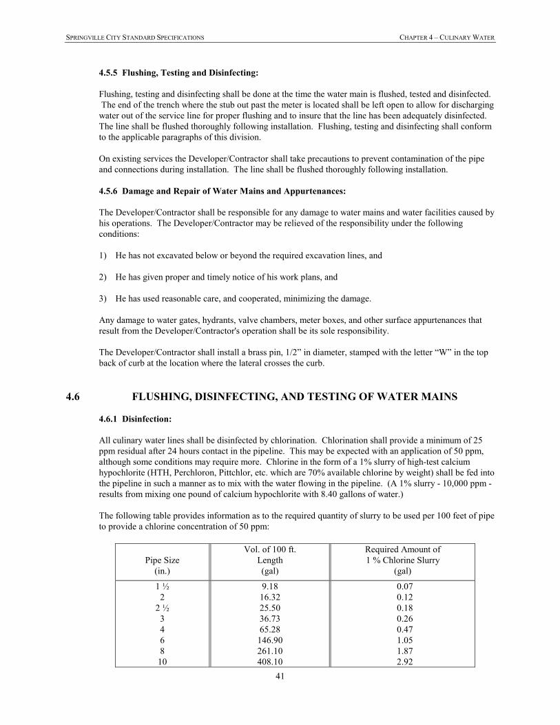
SPRINGVILLE CITY STANDARD SPECIFICATIONS CHAPTER 4 – CULINARY WATER
41
4.5.5 Flushing, Testing and Disinfecting:
Flushing, testing and disinfecting shall be done at the time the water main is flushed, tested and disinfected.
The end of the trench where the stub out past the meter is located shall be left open to allow for discharging
water out of the service line for proper flushing and to insure that the line has been adequately disinfected.
The line shall be flushed thoroughly following installation. Flushing, testing and disinfecting shall conform
to the applicable paragraphs of this division.
On existing services the Developer/Contractor shall take precautions to prevent contamination of the pipe
and connections during installation. The line shall be flushed thoroughly following installation.
4.5.6 Damage and Repair of Water Mains and Appurtenances:
The Developer/Contractor shall be responsible for any damage to water mains and water facilities caused by
his operations. The Developer/Contractor may be relieved of the responsibility under the following
conditions:
1) He has not excavated below or beyond the required excavation lines, and
2) He has given proper and timely notice of his work plans, and
3) He has used reasonable care, and cooperated, minimizing the damage.
Any damage to water gates, hydrants, valve chambers, meter boxes, and other surface appurtenances that
result from the Developer/Contractor's operation shall be its sole responsibility.
The Developer/Contractor shall install a brass pin, 1/2” in diameter, stamped with the letter “W” in the top
back of curb at the location where the lateral crosses the curb.
4.6 FLUSHING, DISINFECTING, AND TESTING OF WATER MAINS
4.6.1 Disinfection:
All culinary water lines shall be disinfected by chlorination. Chlorination shall provide a minimum of 25
ppm residual after 24 hours contact in the pipeline. This may be expected with an application of 50 ppm,
although some conditions may require more. Chlorine in the form of a 1% slurry of high-test calcium
hypochlorite (HTH, Perchloron, Pittchlor, etc. which are 70% available chlorine by weight) shall be fed into the pipeline in such a manner as to mix with the water flowing in the pipeline. (A 1% slurry - 10,000 ppm -
results from mixing one pound of calcium hypochlorite with 8.40 gallons of water.)
The following table provides information as to the required quantity of slurry to be used per 100 feet of pipe
to provide a chlorine concentration of 50 ppm:
Pipe Size
(in.)
Vol. of 100 ft.
Length
(gal)
Required Amount of
1 % Chlorine Slurry
(gal)
1 ½
2
2 ½
3
4
6
8
10
9.18
16.32
25.50
36.73
65.28
146.90
261.10
408.10
0.07
0.12
0.18
0.26
0.47
1.05
1.87
2.92
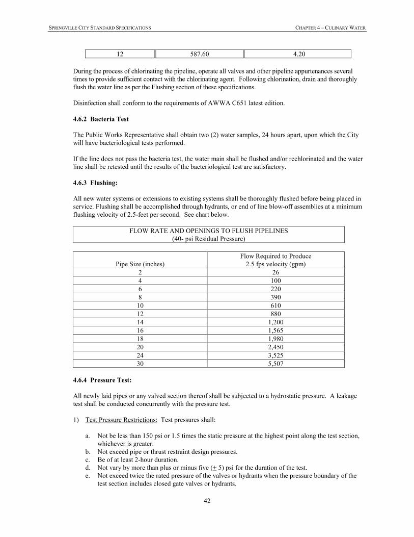
SPRINGVILLE CITY STANDARD SPECIFICATIONS CHAPTER 4 – CULINARY WATER
42
12 587.60 4.20
During the process of chlorinating the pipeline, operate all valves and other pipeline appurtenances several
times to provide sufficient contact with the chlorinating agent. Following chlorination, drain and thoroughly
flush the water line as per the Flushing section of these specifications.
Disinfection shall conform to the requirements of AWWA C651 latest edition.
4.6.2 Bacteria Test
The Public Works Representative shall obtain two (2) water samples, 24 hours apart, upon which the City
will have bacteriological tests performed.
If the line does not pass the bacteria test, the water main shall be flushed and/or rechlorinated and the water
line shall be retested until the results of the bacteriological test are satisfactory.
4.6.3 Flushing:
All new water systems or extensions to existing systems shall be thoroughly flushed before being placed in
service. Flushing shall be accomplished through hydrants, or end of line blow-off assemblies at a minimum
flushing velocity of 2.5-feet per second. See chart below.
FLOW RATE AND OPENINGS TO FLUSH PIPELINES
(40- psi Residual Pressure)
Pipe Size (inches)
Flow Required to Produce
2.5 fps velocity (gpm)
2 26
4 100
6 220
8 390
10 610
12 880
14 1,200
16 1,565
18 1,980
20 2,450
24 3,525
30 5,507
4.6.4 Pressure Test:
All newly laid pipes or any valved section thereof shall be subjected to a hydrostatic pressure. A leakage
test shall be conducted concurrently with the pressure test.
1) Test Pressure Restrictions: Test pressures shall:
a. Not be less than 150 psi or 1.5 times the static pressure at the highest point along the test section,
whichever is greater.
b. Not exceed pipe or thrust restraint design pressures.
c. Be of at least 2-hour duration.
d. Not vary by more than plus or minus five (+ 5) psi for the duration of the test.
e. Not exceed twice the rated pressure of the valves or hydrants when the pressure boundary of the
test section includes closed gate valves or hydrants.
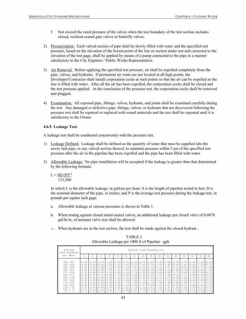
SPRINGVILLE CITY STANDARD SPECIFICATIONS CHAPTER 4 – CULINARY WATER
43
f. Not exceed the rated pressure of the valves when the test boundary of the test section includes
closed, resilient-seated gate valves or butterfly valves.
2) Pressurization: Each valved section of pipe shall be slowly filled with water and the specified test
pressure, based on the elevation of the lowest point of the line or section under test and corrected to the
elevation of the test gage, shall be applied by means of a pump connected to the pipe in a manner
satisfactory to the City Engineer / Public Works Representative.
3) Air Removal: Before applying the specified test pressure, air shall be expelled completely from the
pipe, valves, and hydrants. If permanent air vents are not located at all high points, the
Developer/Contractor shall install corporation cocks at such points so that the air can be expelled as the
line is filled with water. After all the air has been expelled, the corporation cocks shall be closed and
the test pressure applied. At the conclusion of the pressure test, the corporation cocks shall be removed
and plugged.
4) Examination: All exposed pipe, fittings, valves, hydrants, and joints shall be examined carefully during
the test. Any damaged or defective pipe, fittings, valves, or hydrants that are discovered following the
pressure test shall be repaired or replaced with sound materials and the test shall be repeated until it is
satisfactory to the Owner.
4.6.5 Leakage Test:
A leakage test shall be conducted concurrently with the pressure test.
1) Leakage Defined: Leakage shall be defined as the quantity of water that must be supplied into the
newly laid pipe, or any valved section thereof, to maintain pressure within 5 psi of the specified test
pressure after the air in the pipeline has been expelled and the pipe has been filled with water.
2) Allowable Leakage: No pipe installation will be accepted if the leakage is greater than that determined
by the following formula:
L = SD (P)0.5
133,200
In which L is the allowable leakage, in gallons per hour; S is the length of pipeline tested in feet; D is
the nominal diameter of the pipe, in inches; and P is the average test pressure during the leakage test, in
pounds per square inch gage.
a. Allowable leakage at various pressures is shown in Table 1.
b. When testing against closed metal-seated valves, an additional leakage per closed valve of 0.0078
gal/hr/in. of nominal valve size shall be allowed.
c. When hydrants are in the test section, the test shall be made against the closed hydrant.
TABLE 1
Allowable Leakage per 1000 ft of Pipeline - gph
Average
Test Pressure
Nominal Pipe Diameter—in.
psi (Bar)
3 4 6 8 10 12 14 16 18 20 24 30 36 42 48 54
450 (31) 400 (28) 350 (24) 300 (21) 275 (19) 250 (17) 225 (16) 200 (14) 175 (12) 150 (10) 125 ( 9) 100 ( 7)
0.48 0.45 0.42 0.39 0.37 0.36 0.34 0.32 0.30 0.28 0.25 0.23
0.64 0.60 0.56 0.52 0.50 0.47 0.45 0.43 0.40 0.37 0.34 0.30
0.95 0.90 0.84 0.78 0.75 0.71 0.68 0.64 0.59 0.55 0.50 0.45
1.27 1.20 1.12 1.04 1.00 0.95 0.90 0.85 0.80 0.74 0.67 0.60
1.59 1.50 1.40 1.30 1.24 1.19 1.13 1.06 0.99 0.92 0.84 0.75
1.91 1.80 1.69 1.56 1.49 1.42 1.35 1.28 1.19 1.10 1.01 0.90
2.23 2.10 1.97 1.82 1.74 1.66 1.58 1.48 1.39 1.29 1.18 1.05
2.55 2.40 2.25 2.08 1.99 1.90 1.80 1.70 1.59 1.47 1.34 1.20
2.87 2.70 2.53 2.34 2.24 2.14 2.03 1.91 1.79 1.66 1.51 1.35
3.18 3.00 2.81 2.60 2.49 2.37 2.25 2.12 1.98 1.84 1.68 1.50
3.82 3.60 3.37 3.12 2.99 2.85 2.70 2.55 2.38 2.21 2.01 1.80
4.78 4.50 4.21 3.90 3.73 3.56 3.38 3.19 2.98 2.76 2.52 2.25
5.73 5.41 5.06 4.68 4.48 4.27 4.05 3.82 3.58 3.31 3.02 2.70
6.69 6.31 5.90 5.46 5.23 4.99 4.73 4.46 4.17 3.86 3.53 3.15
7.64 7.21 6.74 6.24 5.98 5.70 5.41 5.09 4.77 4.41 4.03 3.60
8.60 8.11 7.58 7.02 6.72 6.41 6.03 5.73 5.36 4.97 4.53 4.05
SPRINGVILLE CITY STANDARD SPECIFICATIONS CHAPTER 4 – CULINARY WATER
44
*If the pipeline under test contains sections of various diameters, the allowable leakage will be the sum of the computed leakage for each size.
**To obtain leakage in liters/hour, multiply the values in the table by 3.785.
3) Examination: All exposed pipe, fittings, valves, hydrants, and joints shall be examined carefully during
the test. Any damaged or defective pipe, fittings, valves, or hydrants that are discovered during the
leakage test shall be repaired or replaced with sound materials and the test shall be repeated. Repairs
or replacements to the pipeline and subsequent leakage testing shall be performed as necessary for the
pipeline to pass the leakage test.
4) Acceptance of Installation: Acceptance shall be determined on the basis of allowable leakage. If any
test of pipe laid discloses leakage greater than specified, the Developer/Contractor shall, at its own
expense, locate and repair the defective material until the leakage is within the specified allowance.
All visible leaks are to be repaired regardless of the amount of leakage.
4.7 RESILIENT SEATED GATE VALVE
Valves in sizes 4" through 10" shall be of the iron body, non-rising bronze stem, resilient seated type, manufactured
to equal or exceed all applicable AWWA standards latest revision and all specific requirements outlined in these
specifications.
All gate valves shall be WATEROUS Series 2500 or MUELLER A-2361.
4.8 BUTTERFLY VALVE
Valves in sizes 12” and larger shall be butterfly valves manufactured to equal or exceed all applicable AWWA
standards latest revision and all specific requirements outlined in these specifications.
All butterfly valves shall be M&H 4500 or MUELLER LINESEAL III or approved equal.
4.9 VALVE BOXES
Valves and valve boxes shall be installed as required in these Specifications and Standard Drawings. Valves and
valve boxes shall be set plumb. Valve boxes shall be centered directly over the valve. If the top of the valve nut is
greater than five (5) feet below finished grade a valve nut extension shall be required. Earth fill shall be carefully
tamped around the valve box to a distance of four (4) feet on all sides of the box, or to the undisturbed trench face if
less than four (4) feet. Valves shall have the interiors cleaned of all foreign matter before installation.
All buried valves shall be installed complete with two-piece, cast iron, 5-1/4-inch shaft valve box with lid. The lid
shall have the words “WATER” or “FIRE” cast in the metal depending on the application.
4.9.1 Placement of Concrete Collars
Valve boxes shall be set to the finished grade and contour of the street. Valve boxes shall be protected
during backfilling and compaction of the road base and during the placing or replacing of road surfaces.
Any valve boxes damaged or broken shall be replaced by the Developer/Contractor at its expense. Prior to
paving, the valve box shall be GPS-located by the Developer / Contractor (shot at the center of the valve
box) and set six (6) inches below the finished grade. After paving the asphalt shall be removed, and the
valve box shall be raised to match the grade and slope of the finished road surface.
Road base around the valve box shall be re-compacted, and the concrete collar placed. Valve boxes placed
in asphalt surfacing shall be constructed such that the cast iron ring is one-quarter inch (1/4”) lower than the
pavement. Valve boxes must be cleaned of all debris after setting of collars.
SPRINGVILLE CITY STANDARD SPECIFICATIONS CHAPTER 4 – CULINARY WATER
45
4.10 FIRE HYDRANTS
Fire hydrants shall be "traffic model" type designed to conform to AWWA Specifications. Hydrants shall be
Mueller "Super Centurion 250" or Waterous "Pacer".
4.11 AIR RELEASE and VACUUM RELIEF VALVE
Air release and vacuum relief valves shall fulfill functions of air release (permit escape of air accumulated in line at
high point of elevation while line is under pressure) and vacuum relief (allow air to enter the pipe and prevent its
potential collapse due to the formation of a vacuum condition caused by rapid withdrawal of water) . Air and vacuum
relief valves shall be placed at high points or uphill end points in the system. The need for air relief valves should be
minimized through the engineering design of the line.
Air release and vacuum relief valves shall be single-body, standard combination valves rated for a minimum working
pressure of 150 psi, unless otherwise indicated. (APCO Model 145C or approved equal as indicated on Standard
Drawings). Bodies shall be of high strength cast iron. The float, seat, and all moving parts shall be constructed of
Type 316 stainless steel. Seat washers and gaskets shall be of a material insuring water tightness with
a minimum of maintenance. The valve exterior shall be painted with shop-applied primer suitable for contact with
potable water. The connection to the main for the air release and vacuum relief valve shall be service clamp, Ford
FS202 or approved equal. Tapping the main through the service clamp will be accomplished with standard tapping
equipment before the system is put into service. Typical small distribution mains (4” to 12”) shall have the typical 2-
inch combination air-vacuum valves per the Standard Drawings. Larger water main pipelines shall have valves
which are engineered and sized to compensate for the size of pipe and the length of run.
Valves shall be installed in a 5-foot diameter precast manhole base with a standard manhole frame and lid (D&L
1180 or approved equal) per Standard Drawing. The manhole lid shall read “WATER’ or “PRESSURIZED
IRRIGATION” as appropriate. Set the manhole base and lid plumb and as detailed. Center the manhole over valve.
For pressurized irrigation use, the valve shall vent directly into the vault.
SPRINGVILLE CITY STANDARD SPECIFICATIONS CHAPTER 5 – STORM DRAIN & IRRIGATION
46
CHAPTER 5 - STORM DRAIN & IRRIGATION
5.1 GENERAL
This section covers the requirements for materials and installation of storm drain and other gravity flow pipes,
manholes, and inlet boxes within the public right-of-way.
5.2 MINIMUM SIZES
In no case shall storm drain or irrigation mains be less than fifteen inches (15”) in diameter.
Minimum manhole interior diameter is five feet (5’) for all storm drain or irrigation manholes. Larger sizes may be
required based on pipe size.
Minimum curb inlet box size is two feet by three feet (2’ x 3’). Precast boxes with knock-outs are allowed. Larger
boxes to accommodate oil /debris separation devices, orifice plates, etc. shall be required as approved by City
Engineer / Public Works Representative.
5.3 PIPE
Pipe used in storm drain and irrigation pipeline construction within the public right-of-way shall be reinforced
concrete pipe Class III, unless otherwise approved by the City Engineer / Public Works Representative, as required
by design loading and fill heights and as follows:
5.3.1 Reinforced Concrete Pipe:
All reinforced concrete pipe shall be of the rubber gasket type, bell and spigot joint design, conforming to
the requirements of the latest revision of ASTM Designation C76. Pipe class shall be a minimum of Class
III or greater, required by design loading and fill heights per the manufacturer.
Bell and spigot joints, including rubber gaskets, shall conform to the requirements of the latest revision of
ASTM Designation C443. The pipe joint shall be so designed as to provide for self-centering, and when
assembled, to compress the gasket to form a water tight seal. The gasket shall be confined in a groove on
the spigot, so that pipe movement or hydrostatic pressure cannot displace the gasket
5.3.2 Corrugated High Density Polyethylene Pipe:
Corrugated polyethylene pipe shall be high density polyethylene corrugated exterior with a smooth interior wall
with water-tight joints. Eight to ten (8-10) inch diameter shall meet the requirements of AASHTO M-252 and
have a smooth interior liner. Twelve to thirty six (12-36) inch diameters shall conform to AASHTO M-294
Type S. Forty-two to forty-eight (42-48) inch diameter shall conform to AASHTO MP-6 type. Materials shall
conform to ASTM D-3350. All pipe joints and fittings shall be water tight and conform to AASHTO M-353 or
M-294, and shall be approved by the City Engineer / Public Works Representative. Use of HDPE pipe within
the public right-of-way is only allowed upon prior approval of the City Engineer.
The pipe and fittings shall be free of foreign inclusions and visible defects. For pipe sizes 12" diameter and
greater, holes of any kind in the corrugation crests or sidewalls shall be considered unacceptable. The ends of
the pipe shall be cut squarely and cleanly so as not to adversely affect joining.
The nominal size for the pipe and fittings is based on the nominal inside diameter of the pipe. Fittings shall be
molded by the manufacturer. Fittings produced by manufacturers other than the supplier of the pipe shall not
be permitted.
SPRINGVILLE CITY STANDARD SPECIFICATIONS CHAPTER 5 – STORM DRAIN & IRRIGATION
47
A manufacturer's certification that the product was manufactured, tested, and supplied in accordance with this
specification shall be furnished to the City Engineer / Public Works Representative upon request.
All fittings, bolts and accessories shall meet applicable specifications of the pipe being used. Use accessories
and gaskets recommended by the manufacturer.
5.4 PIPE LAYING
All storm drain pipes shall be laid with uniform slope between manholes. All pipe installation shall proceed
upgrade on a stable foundation, with joints closely and accurately fitted. Pipes shall be installed with
uniform bearing under the full length of the barrel, with suitable excavations being made to receive pipe
bells. Specific installation requirements for RCP and Corrugated HDPE pipe are listed below:
5.4.1 Reinforced Concrete Pipe:
Rubber gaskets shall be fitted properly in place, and care shall be taken in joining the pipe sections to avoid
twisting of gaskets. Joints shall be clean and dry, and a joint lubricant as recommended by the pipe supplier
shall be applied uniformly to the mating joint surfaces to facilitate easy positive joint closure.
Select material shall be compacted around the pipe to firmly bed the pipe in position. If adjustment of
position of a pipe length is required after being laid, it shall be removed and re-jointed as for a new pipe.
When laying is not in progress, the ends of the pipe shall be closed with a tight-fitting stopper to prevent the
entrance of foreign material.
5.4.2 Corrugated High Density Polyethylene Pipe:
Select material shall be compacted around the pipe to firmly bed the pipe in position. Haunching material (bed
to springline) should be carefully worked under the haunches of the pipe and compacted from the pipe to the
trench wall or two and one half (2-1/2) pipe diameters on each side of the pipe to ensure support. If adjustment
of position of a pipe length is required after being laid, it shall be removed and re-jointed as for a new pipe.
When laying is not in progress, the ends of the pipe shall be closed with a tight-fitting stopper to prevent the
entrance of foreign material.
In addition to the above requirements, all pipe installation shall comply with the specific requirements of the
pipe manufacturer.
5.5 INSTALLATION REQUIREMENTS FOR LINE AND GRADE
All pipe shall be installed accurately to the defined line and grade and verified at every joint with grade-line pipe
laser. Calibration documentation shall be provided to the City upon request.
Variance from established line and grade shall not be greater than one-sixteenth (1/16) inch per inch of pipe diameter
in ten feet, and not to exceed one-half inch in ten feet, provided that such variation does not result in a level or
reverse sloping invert; provided also that variation in the invert elevation between adjoining ends of pipe, due to
non-concentricity of joining surface and pipe interior surfaces, does not exceed one-sixty-fourth (1/64) inch per inch
of pipe diameter, or one-half (1/2) inch maximum.
5.6 GRAVEL FOUNDATION FOR PIPE
Wherever the subgrade material does not afford a sufficiently solid foundation to support the pipe and superimposed
load, or where groundwater must be drained, the subgrade shall be excavated to such depth as may be necessary and
replaced with crushed rock or gravel compacted into place.
SPRINGVILLE CITY STANDARD SPECIFICATIONS CHAPTER 5 – STORM DRAIN & IRRIGATION
48
5.7 PIPE BEDDING
See Section 2.5.3 Pipe Embedment Material Placement
5.8 CLEANING AND TELEVISING
After the pipe lines have been laid and the trench back-filled, all pipes shall be thoroughly cleaned. Cleaning shall
be done using a high-pressure jet cleaning machine, producing a minimum of 800 psi. Waste water and debris shall
not be permitted to enter existing lines, but shall be removed by a vacuum truck at the lowest manhole of the
extension. Such cleaning shall be done by private crews at the expense of the Developer/Contractor.
All mains shall be cleaned and then inspected using a television inspection unit capable of rotating the camera for
overall pipe inspection. The televised inspection of any mains which reveal broken, misaligned or displaced pipe, or
other defects shall be remedied by the contractor as directed by the City Engineer / Public Works Representative.
The Developer/Contractor must provide the City with a DVD of the televising of the pipe and the
Developer/Contractor shall pay all associated costs. The televised inspection shall have the slope of pipe shown on
the DVD throughout the inspection. The televising equipment used must record on the DVD a continuous distance
from the point of beginning. After cleaning and inspection have been completed, the pipe shall be tested as
instructed in the following section.
5.9 TESTS
The Developer/Contractor will be required to conduct an air test and in the case of HDPE pipe a “GO/NO-GO”
mandrel test in the presence of the City Engineer / Public Works Representative. If these tests prove to be
inconclusive, any or all of the other required tests shall be conducted in the presence of the City Engineer / Public
Works Representative or his representative. Tests shall be performed as follows:
5.9.1 Air Testing:
The Developer/Contractor or his representative (a qualified firm or individual agreed upon by the City
Engineer / Public Works Representative and the Developer/Contractor) shall furnish labor, equipment, and
materials, including pumps and compressors, and shall perform, in the presence of the City Engineer /
Public Works Representative, air tests of the completed pipe before it can be placed in service. Each section
of pipeline between manholes shall be tested individually. Each test section shall be pressurized to 4.0 psi.
For the purpose of stabilizing the air pressure in each test section, the 4.0 psi pressure shall be maintained
for a two-minute period. Each test section shall then be re-pressurized to 4.0 psi for a period of four
minutes. The test section shall be accepted if, after four minutes, the pressure gauge indicates 3.5 psi or
greater. Failure of the Developer/Contractor's testing equipment to properly function shall render the test
unacceptable. All faulty sections of pipeline shall be repaired and re-tested until the minimum air testing
requirements have been met
5.9.2 GO/NO-GO” Mandrel Proof Testing (For HDPE Pipe Only):
Not less than thirty (30) days after installation of the flexible sewer or drain pipe, the Contractor shall test
the buried pipe to insure that ring-deflection of the pipe does not exceed five percent (5%) of the pipe's
specified minimum inside diameter (ID). This proof test shall establish that the Contractor has installed the
flexible pipe in full compliance with the Project Specifications thereby providing required pipe/soil
structural strength.
The Contractor, with the City Engineer / Public Works Representative present, shall pull a "Go/No-Go"
Mandrel, inspected and approved by the City Engineer / Public Works Representative, through the full
length of installed flexible pipe. The Mandrel shall be fabricated from suitable metal with a minimum of
nine (9) properly sized radial fins mounted upon a center pulling shaft. In any case, the Mandrel shall be
provided with an odd number of rigidly mounted radial fins. The Mandrel shall be provided with a proof-
sizing ring that can demonstrate that the Mandrel's minimum outside diameter (OD) is not less than ninety-
SPRINGVILLE CITY STANDARD SPECIFICATIONS CHAPTER 5 – STORM DRAIN & IRRIGATION
49
five percent (95%) of the specified minimum inside diameter of the installed flexible pipe. The Mandrel
shall be pulled by the Contractor through one-hundred percent (100%) of the installed flexible pipe without
using mechanical equipment. Failure of the Mandrel to pass through a pipeline shall be deemed evidence of
inadequate installation by the Contractor not in compliance with the Project Specifications.
5.10 MANHOLES OR JUNCTION BOXES
Manholes and junction boxes shall be installed at the locations and at the depth shown on the drawings. Manholes or
boxes shall be furnished complete with cast-iron rings and covers. No steps shall be installed in any manhole or box.
Unless otherwise noted manhole bases or boxes shall be precast. Concrete for manholes and boxes shall comply
with the requirements of Chapter 9 – Portland Cement Concrete.
All manholes shall be precast, sectional, reinforced concrete pipe sixty-inch (60") diameter minimum, or larger, as
specified. Sections shall conform to all requirements of ASTM Designation C478-88 (or latest revision) for Precast
Reinforced Concrete Manhole Sections.
All joint surfaces of precast sections and the face of the manhole base shall be thoroughly cleaned prior to setting
precast sections. All joints shall be set in mastic. All joints shall be water tight and free from appreciable
irregularities in the interior wall surface.
5.10.1 Setting of Manhole Frames and Covers and Placement of Concrete Collars
Covers shall be set to the finished grade and contour of the street. Rings and covers shall be protected
during backfilling and compaction of the road base and during the placing or replacing of road surfaces.
Any rings or covers damaged or broken shall be replaced by the Developer/Contractor at its expense. Prior
to paving, the manhole ring and cover shall be GPS-located by the Developer / Contractor (shot at the
center of the ring) and set below the finished road base elevation. After paving the asphalt shall be
removed, and the manhole ring and cover shall be raised to match the grade and slope of the finished road
surface and shall use the WHIRLyGIG manhole riser/collar system or approved equal.
Road base around the manhole ring and cover shall be recompacted, and the concrete collar placed.
Manholes and boxes placed in asphalt surfacing shall be constructed such that the cast iron ring is one-
quarter inch (1/4”) lower than the pavement. The top of all concrete lids shall be a minimum of eight inches
(8”) and a maximum of twelve-inches (12”) below the finished road surface. Manholes and boxes must be
cleaned of all debris after setting of collars.
See Standard Drawings for concrete collar details.
5.11 PIPE CONNECTIONS
Pipe connections to manholes or other structures shall be achieved by the use of a concrete collar (see Chapter 9,
Portland Cement Concrete) on the exterior of the structure around the pipe creating a watertight seal between the
manhole and the pipe. Non-shrink grout shall be used on interior of the structure, filling all voids and creating a
watertight seal between the manhole and the pipe. Pipes shall be cut flush with interior of the structure in a
workmanlike manner. Pipe shall be supported by proper trench foundation outside of the structure and shall not rely
on the structure for support.
Connections to an existing storm drain / irrigation system shall be made by installation of a manhole. The City
Engineer / Public Works Representative shall approve connection locations and methods.
SPRINGVILLE CITY STANDARD SPECIFICATIONS CHAPTER 6 – SANITARY SEWER
50
CHAPTER 6 - SANITARY SEWER
6.1 GENERAL
This section covers the requirements for PVC plastic sewer pipe materials and installation in sanitary sewer
construction.
6.2 PIPE
PVC gravity sewer pipe and fittings shall conform to ASTM D3034, for diameters from four-inch (4") to fifteen-inch
(15") and ASTM F679 for eighteen-inch (18") to twenty-seven-inch (27"), with integral bell gasket joints. Rubber
gaskets shall be factory installed and conform to ASTM F477. Pipe shall be made of PVC plastic having a cell
classification of 12454A or 13364B (with minimum tensile modulus of 500,000 PSI) as defined in ASTM D1784
and shall have a SDR of 35 and minimum pipe stiffness of 46PSI according to ASTM test D2412.
Pipe shall be installed in compliance with ASTM D2321 and the manufacturer's requirements.
6.3 FITTINGS
Fittings shall be made of PVC plastic conforming to ASTM D1784 and a cell classification as outlined in ASTM
D3034.
6.4 PIPE LAYING
Pipes shall be laid with uniform slope between manholes. All pipe installation shall proceed upgrade on a stable
foundation, with joints closely and accurately fitted. Rubber gaskets shall be fitted properly in place, and care shall
be taken in joining the pipe sections to avoid twisting of gaskets. Joints shall be clean and dry, and a joint lubricant
as recommended by the pipe supplier shall be applied uniformly to the mating joint surfaces to facilitate easy
positive joint closure.
Pipe shall be installed with uniform bearing under the full length of the barrel, with suitable excavations being made
to receive pipe bells.
Select material shall be compacted around the pipe to firmly bed the pipe in position. If adjustment of position of a
pipe length is required after being laid, it shall be removed and re-jointed as for a new pipe. When laying is not in
progress, the ends of the pipe shall be closed with a tight-fitting stopper to prevent the entrance of foreign material.
In addition to the above requirements, all pipe installation shall comply with the specific requirements of the pipe
manufacturer.
6.5 GRAVEL FOUNDATION FOR PIPE
Wherever the subgrade material does not afford a sufficiently solid foundation to support the pipe and superimposed
load, and where groundwater must be drained, the subgrade shall be excavated to such depth as may be necessary
and replaced with crushed rock or gravel compacted into place.
6.6 INSTALLATION REQUIREMENTS FOR LINE AND GRADE
All pipe shall be installed accurately to the defined line and grade and verified at every joint with grade-line pipe
laser. Calibration documentation shall be provided to the City upon request.
Variance from established line and grade shall not be greater than one sixteenth (1/16) inch per inch of pipe diameter
in ten feet, and not to exceed one half inch in ten feet, provided that such variation does not result in a level or
reverse sloping invert; provided also that variation in the invert elevation between adjoining ends of pipe, due to
SPRINGVILLE CITY STANDARD SPECIFICATIONS CHAPTER 6 – SANITARY SEWER
51
non-concentricity of joining surface and pipe interior surfaces, does not exceed one sixty fourth (1/64) inch per inch
of pipe diameter, or one half (1/2) inch maximum.
6.7 PIPE BEDDING
See Section 2.5.3 Pipe Embedment Material Placement
6.8 CLEANING AND TELEVISING
After the pipe lines have been laid and the trench back-filled, all pipes shall be thoroughly cleaned. Cleaning shall
be accomplished using a high-pressure jet cleaning machine, producing a minimum of 800 psi. Waste water and
debris shall not be permitted to enter sewer lines in service, but shall be removed by a vacuum truck at the lowest
manhole of the extension. Such cleaning shall be done by private crews at the expense of the Developer/Contractor.
All sewer pipe mains and laterals shall be cleaned and then inspected using a television inspection unit. The
televised inspection of any pipes which reveal broken, misaligned or displaced pipe, or other defects shall be
remedied by the contractor as directed by the City Engineer / Public Works Representative. The
Developer/Contractor must provide the City with a DVD of the televising of the pipe and the Developer/Contractor
shall pay all associated costs. The televised inspection shall have the slope of pipe shown on the DVD throughout
the inspection. The televising equipment used must record on the DVD a continuous distance from the point of
beginning. After cleaning and inspection have been completed, the pipe shall be tested as instructed in the following
section.
6.9 TESTS
The Developer/Contractor will be required to conduct an air test and displacement test in the presence of the City
Engineer / Public Works Representative. If these tests prove to be inconclusive, any or all of the other required tests
shall be conducted in the presence of the City Engineer / Public Works Representative or his representative. Tests
shall be performed as follows:
6.9.1 Infiltration Test:
The Developer / Contractor shall furnish labor, equipment, and materials, including pumps, and shall assist
the City Engineer / Public Works Representative in making infiltration tests of the completed sewer before
it can be placed into service. The Developer/Contractor shall furnish and install the measuring weirs or
other measuring devices. The length of line to be tested at any time shall be subject to the approval of the
City Engineer / Public Works Representative. The maximum allowable infiltration shall not exceed one-
hundred-fifty (150) gallons per inch diameter per mile per twenty-four hours (24 hrs) for all installed sewer
pipe. If the quantity of infiltration is in excess of the maximum allowable, the leaking joints shall be
repaired to the satisfaction of the City Engineer / Public Works Representative at the expense of the
Developer/Contractor.
6.9.2 Exfiltration Test:
The Developer/Contractor shall furnish labor, equipment, and materials, including pumps, and shall assist
the City Engineer / Public Works Representative in making exfiltration tests of the completed sewer before
it can be placed into service. The length of line to be tested at one time shall be limited to the length
between adjacent manholes. The maximum allowable exfiltration shall not exceed one-hundred-fifty (150)
gallons per inch diameter per mile per 24 hours for all installed sewer pipe. The end of the sewer line,
which projects into the manhole, shall be plugged. The pipe shall then be filled with water from the upper
manhole, and the line maintained under a light pressure of four feet (4') of head. The inflow of water
necessary to maintain this head shall be recorded as the leakage of the system. If the quantity of exfiltration
is in excess of the maximum allowable, the leaking joints shall be repaired to the satisfaction of the City
Engineer / Public Works Representative at the expense of the Developer/Contractor.
SPRINGVILLE CITY STANDARD SPECIFICATIONS CHAPTER 6 – SANITARY SEWER
52
6.9.3 Air Testing:
The Developer/Contractor or his representative (a qualified firm or individual agreed upon by the City
Engineer / Public Works Representative and the Developer/Contractor) shall furnish labor, equipment, and
materials, including pumps and compressors, and shall perform, in the presence of the City Engineer /
Public Works Representative, air tests of the completed pipe before it can be placed in service. Each
section of sanitary sewer pipeline between manholes shall be tested after all the service laterals (and plugs)
have been installed. Each test section shall be pressurized to four (4.0) psi. For the purpose of stabilizing
the air pressure in each test section, the four (4.0) psi pressure shall be maintained for a two-minute period.
Each test section shall then be re-pressurized to 4.0 psi for a period of four minutes. The test section shall
be accepted if, after four minutes, the pressure gauge indicates 3.5 psi or greater. Failure of the Developer /
Contractor's testing equipment to properly function shall render the test unacceptable. All faulty sections of
pipeline shall be repaired and re-tested until the minimum air testing requirements have been met.
6.9.4 “Go/No-Go” Mandrel Proof Testing:
Not less than thirty (30) days after installation of the flexible sewer or drain pipe, the Contractor shall test
the buried pipe to insure that ring-deflection of the pipe does not exceed five percent (5%) of the pipe's
specified minimum inside diameter (ID). This proof test shall establish that the Contractor has installed the
flexible pipe in full compliance with the Project Specifications thereby providing required pipe/soil
structural strength.
The Contractor, with the City Engineer / Public Works Representative present, shall pull a "Go/No-Go"
Mandrel, inspected and approved by the City Engineer / Public Works Representative, through the full
length of installed flexible pipe. The Mandrel shall be fabricated from suitable metal with a minimum of
nine (9) properly sized radial fins mounted upon a center pulling shaft. In any case, the Mandrel shall be
provided with an odd number of rigidly mounted radial fins. The Mandrel shall be provided with a proof-
sizing ring that can demonstrate that the Mandrel's minimum outside diameter (OD) is not less than ninety-
five percent (95%) of the specified minimum inside diameter of the installed flexible pipe. The Mandrel
shall be pulled by the Contractor through one-hundred percent (100%) of the installed flexible pipe without
using mechanical equipment. Failure of the Mandrel to pass through a pipeline shall be deemed evidence of
inadequate installation by the Contractor not in compliance with the Project Specifications.
6.10 MANHOLE CONNECTIONS
PVC pipe connections to manholes shall be achieved by use of manhole coupling adapters, rubber gaskets, or
positive seal gasket system with 300 series nonmagnetic stainless steel bands such as PSX: Direct Drive or approved
equal. PVC may not be grouted directly to concrete.
Positive seal gasket systems boot shall be constructed solely of synthetic or natural rubber, shall have a minimum
tensil strength of 1600 psi and have a minimum wall thickness of 0.275 inches. The boot shall either be “cast-in-
place” in the precast base or attached to the precast base by means of an internal expanding band. When the boot is
attached to the precast base, a water tight seal between the boot and the precast base must be accomplished. An
external band (take-up clamp) shall be supplied and used to clamp and seal the boot to the pipe. The band shall be
made of 300 series nonmagnetic stainless steel. After the band has been placed, it shall be completely coated with a
bituminous material approved by the City Engineer / Public Works Representative.
6.11 SEWER LATERAL CONNECTIONS
All sewer lateral connections onto new sewer mains shall be made through pre-formed wye fittings installed in the
main line at the time of main line installation. The minimum spacing between sewer lateral connections using a wye
is thirty feet (30’). When spacing between sewer laterals is less than thirty feet (30’), Inserta Tee connections must
be used.
SPRINGVILLE CITY STANDARD SPECIFICATIONS CHAPTER 6 – SANITARY SEWER
53
Connections onto existing sewer mains shall be made with Inserta Tee connections or approved equal. All
connections by Inserta Tees on existing sewer mains shall be done with a sewer tapping machine and all required
fittings and materials. Connections shall be made as shown on the Standard Drawing and at the location specified
herein, shown on the improvement drawings or as staked in the field.
6.12 SEWER SERVICE LATERALS
New service laterals shall be constructed with materials and procedures as specified herein.
In no case shall sanitary sewer laterals be less than four inches (4”) in diameter.
6.12.1 Extent of Laterals and Location of Laterals:
New sewer laterals installed to lots shall be located ten feet (10’) in the downhill direction from the lot
centerline and a minimum of ten feet (10’) from the culinary water service. Service laterals shall extend
from the sewer main to a point fifteen feet (15') beyond the street right-of-way line unless shown or staked
otherwise. Laterals shall be capped with a cap suitable to withstand test pressure and prevent any leakage
into or out of the lateral.
Sewer cleanouts shall be installed every one-hundred feet (100’) maximum.
Lateral connections directly into a manhole shall not be allowed.
A two-inch by four-inch (2” x 4”) lumber marker, with the top twelve inches (12") painted green, extending
from the end of the sewer lateral to a minimum of twelve inches (12”) above finished grade, shall be
installed to clearly mark the end of each lateral line. In addition to the 2” x 4” lumber marker, the
Developer/Contractor shall install a brass pin, 1/2” in diameter, stamped with the letter “S” in the top back
of curb at the location where the sewer lateral crosses the curb.
When an existing sewer lateral is encountered along the line and grade of a new pipeline it shall be
relocated using appropriate pipe and fittings and graded to insure adequate slope to drain properly.
Minimum slope shall be one-quarter-inch (1/4") per foot.
6.12.2 Excavation and Backfill:
Trench excavation and backfill shall conform to the applicable paragraphs of Chapter 2 and the bedding
requirements of Section 2.5.3 Pipe Embedment Material Placement.
6.12.3 Pipe:
Pipe used for new service laterals shall be PVC Plastic Pipe conforming to ASTM D3034 SDR 35.
6.12.4 Cover Over Sewer Lateral Lines:
There shall be a minimum of 3 feet of cover over all sewer lateral lines.
6.12.5 Testing:
The service laterals shall be tested as a part of the sewer main to which they are connected.
6.12.6 Damage and Repairs of Sewers and Appurtenances:
The Developer/Contractor shall be responsible for the protection of existing improvements, and any damage
resulting from its operations shall be its sole responsibility.
SPRINGVILLE CITY STANDARD SPECIFICATIONS CHAPTER 6 – SANITARY SEWER
54
Damage to the sewers, laterals, or appurtenances shall be repaired by acceptable and approved methods.
6.13 ORANGEBURG PIPE
All Orangeburg pipe (currently in service) encountered during construction shall be completely removed and
replaced to current standards.
SPRINGVILLE CITY STANDARD SPECIFICATIONS CHAPTER 7 – MANHOLES
55
CHAPTER 7 - MANHOLES
7.1 GENERAL
This division covers the requirements for manhole materials and installation. Manholes shall be installed at the
locations and at the depth shown on the drawings. Manholes shall be furnished complete with cast-iron rings and
covers. No steps shall be installed in any manhole.
7.1.1 Manhole Sizing:
Minimum manhole interior diameter is four (4) feet for manholes with one inlet and one outlet pipe.
Manholes with two or more inlet pipes and one outlet pipe shall be a minimum of five (5) feet in diameter.
7.2 CONCRETE BASE
Unless otherwise noted manhole bases shall be precast and shall have pipe inverts and a resilient connection between
pipe and manhole for each pipe connecting to the manhole.
Where sewer lines pass through or enter manholes, the invert channels shall be smooth and semi-circular in cross
section, conforming to the details shown on the Drawings. Changes of direction of flow within the manholes shall be
made with a smooth curve with as long a radius as possible. The floor of the manhole outside the flow channels shall
be smooth and slope toward the channel at not less than one-half inch (1/2“) per foot.
Concrete for manhole bases shall comply with the requirements of Chapter 9, Portland Cement Concrete, of these
Specifications.
7.3 WALL AND CONE SECTIONS
All manholes shall be precast, sectional, reinforced concrete pipe forty-eight-inch (48") diameter, or larger, as
specified. Both cylindrical and taper sections shall conform to all requirements of ASTM Designation C478-88 (or
latest revision) for Precast Reinforced Concrete Manhole Sections.
All joint surfaces of precast sections and the face of the manhole base shall be thoroughly cleaned and wet prior to
setting precast sections. All joints, including grade rings, shall be set in mastic or equal butyl rubber gasket. The
joints shall be sealed with a rubber gasket that is permanently flexible and non-shrinking. Gasket must meet or
exceed all requirements of AASHTO M-198 and ASTM C 990 section 6.2.1, Butyl rubber sealants. All joints shall
be water tight and free from appreciable irregularities in the interior wall surface.
7.4 DROP MANHOLES
When the difference in elevation of an incoming sewer is twenty-four inches (24”) or greater a drop manhole shall be
used. The drop manhole shall be constructed as shown in the Standard Drawings. The drop pipe assembly (outside
of the manhole) shall be PVC pipe with appropriate fittings.
When the difference in elevation of an incoming sewer is less than twenty-four inches (24”) the invert channel shall
be smooth and semi-circular in cross section, conforming to the details shown on the Standard Drawings.
7.5 MANHOLE RINGS AND COVERS All iron casting shall conform to the requirements of ASTM Designation A48 (Class 35) for grey iron castings, free from blowholes and shrinkage defects. Castings shall be free from fins and burrs and shall be shot-blasted to remove sand and other foreign matter.
Rings and covers shall be equal to the twenty-four inch (24") Standard circular, with machined bearing surfaces,
gravity, solid, non-rocking type. The minimum weight of the cover shall be one hundred sixty (160) pounds. The
SPRINGVILLE CITY STANDARD SPECIFICATIONS CHAPTER 7 – MANHOLES
56
minimum weight of the ring shall be two hundred eighty (280 lbs.). No flat rings and covers shall be allowed unless
approved by the City Engineer / Public Works Representative. The tops of the cover and ring shall be flush and
there shall be 1/8-inch clearance between the cover and the ring. In addition to the foundry name and year of
manufacture, the cover shall be marked "SEWER."
7.5.1 Setting of Manhole Frames and Covers and Placement of Concrete Collars
Covers shall be set to the finished grade and contour of the street. Rings and covers shall be protected
during backfilling and compaction of the road base and during the placing or replacing of road surfaces.
Any rings or covers damaged or broken shall be replaced by the Developer/Contractor at its expense. Prior
to paving, the manhole ring and cover shall be GPS-located by the Developer / Contractor (shot at the
center of the ring) and set below the finished road base elevation. After paving the asphalt shall be
removed, and the manhole ring and cover shall be raised to match the grade and slope of the finished road
surface and shall use the WHIRLyGIG manhole riser/collar system.
Road base around the manhole ring and cover shall be recompacted, and the concrete collar placed.
Manholes placed in asphalt surfacing shall be constructed such that the cast iron ring is one-quarter inch
(1/4”) lower than the pavement. The top of all cone sections shall be a minimum of eight inches (8”) and a
maximum of twelve-inches (12”) below the finished road surface. Manholes must be cleaned of all debris
after setting of collar.
See Standard Drawings for Concrete collar details.
7.6 CONNECTIONS TO EXISTING SEWER MAINS
Manholes used to connect to existing sewer lines shall be plumb and centered on the existing pipe. Care shall be
taken not to disturb the alignment of the existing sewer main.
A four-foot (4’) manhole section (of the appropriate diameter based on the size or number of the sewer lines to be
connected) shall be notched and placed over the existing sewer main. The notch in the manhole section shall be
large enough such that the bottom of the manhole section is six-inches (6”) below the bottom of the existing pipe.
Sufficient support shall be placed below the manhole section such that the manhole section does not rest on the
existing pipe. Concrete shall then be placed inside the manhole section around the existing pipe to form the manhole
base to the springline of the existing pipe.
The cutting of the existing sewer pipe shall be done in the presence of the City Engineer / Public Works
Representative. The cut shall be full area of the new base and shall be finished so as to leave no projections that will
restrict the flow or catch solids.
Every precaution shall be taken to prevent any material from entering the sewer main. Any such materials entering
the sewer shall be removed.
7.7 CONNECTIONS TO EXISTING SEWER MANHOLES
All connections to existing manholes shall be made by coring the manhole. A new trough shall form through the
manhole base (via the coring process) such that the new sewer pipe flowline elevation matches the existing trough
flowline elevation. The new pipe connection to the manhole shall be made via a rubber boot as previously described
in these specifications.
7.8 GREASE INTERCEPTORS
All food facilities that generate grease, or have kitchen equipment that has the potential to produce grease including
but not limited to restaurants, institutions, fast food establishments, and camps, are required to install a grease
interceptor. Grease interceptors are required to be sized according to the latest Uniform Plumbing Code (adopted by
the Springville City) at the time of plan check and approval. Minimum size requirement for a grease interceptor is
SPRINGVILLE CITY STANDARD SPECIFICATIONS CHAPTER 7 – MANHOLES
57
1000 gallons. The interceptor should be installed as close to the grease source as possible. Proper setbacks should
be maintained from structures, property lines, etc. to comply with all codes. Location of the interceptor should be
dependent upon easy pump truck access to allow for proper maintenance and should be approved by the
ENGINEER. Toilets, urinals, and other similar fixtures shall not waste through the interceptor. All grease waste shall
enter the interceptor through the inlet pipe only. The inlet, outlet, and baffle fittings should be designed for grease
retention. To allow for proper maintenance, manholes sections to finished grade shall be provided. The manhole
covers should be of gas-tight construction with a minimum opening dimension of 24 inches designed for a minimum
H20 loading.
7.9 POLYMER MANHOLES - HYDROGEN SULFIDE PROTECTION
Corrosion of exposed concrete from the bacterial oxidation of hydrogen sulfide gas to sulfuric acid in the sewer
system has become an issue in several areas of the City. Sulfuric acid is highly corrosive to the cement paste in
concrete and causes tremendous damage to manholes when exposed in high concentrations. In areas where high
concentrations of hydrogen sulfide gas have been noted and/or are expected such as where manholes receive pumped
sewage, experience low sewer flows, experience low velocity sewer flows or experience other conditions that create
hydrogen sulfide gas, the City may require the installation of polymer manholes that are resistant to hydrogen sulfide
corrosion. The polymer manholes shall be Geneva Polymer Manhole Systems or approved equal.
SPRINGVILLE CITY STANDARD SPECIFICATIONS CHAPTER 8 – EARTHWORK
58
CHAPTER 8 - EARTHWORK
8.1 GENERAL
This section defines the requirements for excavation and backfill for manholes, boxes and other structures, and
construction requirements of earth embankments and earth fills, as required by the Standard Drawings and other
sections of these specifications.
8.2 EXCAVATION FOR MANHOLES, BOXES, AND OTHER STRUCTURES
Manholes, boxes and other structures shall be placed on a stable coarse gravel foundation.
Wherever the subgrade material does not afford a sufficiently solid foundation to support structures and
superimposed loads, and where groundwater must be drained, the subgrade shall be excavated to such depth as may
be necessary and replaced with crushed rock or gravel compacted into place. Coarse gravel or crushed stone shall be
used for subsoil reinforcement if satisfactory results can be obtained thereby.
8.3 GRANULAR FOUNDATION BORROW
Granular foundation borrow shall be compacted to not less than 95% of maximum dry density as determined by
ASTM D1557.
8.4 BACKFILL AROUND STRUCTURES
No backfilling around or behind structures shall be initiated until the concrete is fully cured for seven days. Backfill
around structures shall be placed to the lines shown on the drawings, or as directed. After completion of foundation
footings and walls and other construction below the elevation of the final grades, and prior to backfilling, all forms
shall be removed and the excavation shall be cleaned of all trash and debris. Hand compacted fill, including fill
compacted by manually directed power tampers, shall be placed in layers whose thickness before compaction is not
greater than twelve inches (12”). Material for backfilling shall consist of three-inch to four-inch (3”- 4”) well-graded
engineered fill meeting A-1-a, (AASHTO M 145 or ASTM D3282). Recycled concrete will not be allowed for
backfill around structures.
Sieve
Percent Passing
by Weight
4” 100
2” 80 -95
1” 55- 85
3/8” 40 – 70
No. 4 25 – 55
No. 10 20 – 50
No. 40 10 – 30
No. 200 2 - 10
Fill shall be placed in a manner that will prevent damage to the structures and will allow the structures to assume the
loads from the fill gradually and uniformly. The height of the fill adjacent to a structure shall be increased at
approximately the same rate on all sides of the structure. Each layer shall be compacted by hand or machine tampers
or by other suitable equipment to a density equal to 95% of maximum dry density as measured by ASTM D1557.
8.5 CONSTRUCTION OF EMBANKMENTS AND FILLS
8.5.1 Foundation Preparation:
SPRINGVILLE CITY STANDARD SPECIFICATIONS CHAPTER 8 – EARTHWORK
59
Foundations for earth fill shall have all unsuitable materials (such as weeds, sod, roots larger than 1/4-inch
in diameter, vegetation, or other organic material) removed by clearing, stripping, and/or grubbing. Except
as otherwise specified, earth foundation surfaces shall be graded to remove surface irregularities and shall
be scarified parallel to the axis of the fill or otherwise acceptably scored and loosened to a minimum depth
of six inches. The moisture content of the loosened material shall be controlled as specified for the earth
fill, and the surface materials of the foundation shall be compacted and bonded with the first layer of earth
fill as specified for subsequent layers of earth fill.
Earth abutment surfaces shall be free of loose, uncompacted earth in excess of two inches (2”) in depth
normal to the slope and shall be at such a moisture content that the earth fill can be compacted against them
to affect a good bond between the fill and the abutments.
Rock foundation and abutment surfaces shall be cleared of all loose material by hand or other effective
means and shall be free of standing water when fill is placed upon them. Occasional rock outcrops in earth
foundations for earth fill, except in dams and other structures designed to restrain the movement of water,
shall not require special treatment if they do not interfere with compaction of the foundation and initial
layers of the fill or the bond between the foundation and the fill.
8.5.2 Placement:
Fill shall not be placed until the required excavation and foundation preparation have been completed and
the foundation has been inspected and approved by the City Engineer / Public Works Representative and
any Regulatory Agency having authority over the project. Fill shall not be placed upon a frozen surface, nor
shall snow, ice, or frozen material be incorporated in the fill.
Fill shall be placed in approximately horizontal layers. The thickness of each layer before compaction shall
not exceed twelve inches (12”). Materials placed by dumping in piles or windrows shall be spread
uniformly to not more than the specified thickness before being compacted. Hand compacted fill, including
fill compacted by manually-directed power tampers, shall be placed in layers whose thickness before
compaction is not greater than eight inches (8”). All rock whose greatest dimension is larger than three-
inch (3") shall be removed from the material receiving compaction by manually directed power tampers.
Earth fill designed to restrain the movement of water shall be placed so as to meet the following additional
requirements:
1) The distribution of materials throughout each zone shall be essentially uniform, and the fill shall be free
from lenses, pockets, streaks, or layers of material differing substantially in texture or gradation from
the surrounding material.
2) If the surface of any layer becomes too hard and smooth for proper bond with the succeeding layer, it
shall be scarified parallel to the axis of the fill, to a depth of not less than two inches (2”) before the
next layer is placed.
3) The top surfaces of embankments shall be maintained approximately level during construction, except
that a crown or cross-slope of not less than two percent (2%) shall be maintained to ensure effective
drainage, and except as otherwise specified for drain fill zones. If the drawings or specifications
require, or the City Engineer / Public Works Representative directs, that fill be placed at a higher level
in one part of the embankment than another is, the top surface of each part shall be maintained as
specified above.
4) Dam embankments shall be constructed in continuous layers from abutment to abutment except where
openings to facilitate construction of inlet and outlet pipes are specifically authorized in the contract.
5) Embankments built at different levels as described in 3 and 4 shall be constructed so that the slope of
the bonding surfaces between the embankment in place and embankment to be placed is not steeper
than 2-feet horizontal to 1-foot vertical (2:1). The bonding surface of the embankment in place shall be
SPRINGVILLE CITY STANDARD SPECIFICATIONS CHAPTER 8 – EARTHWORK
60
stripped of all loose material, scarified, moistened and recompacted when the new fill is placed against
it. This is needed to ensure a good bond with the new fill, to obtain the specified moisture content and
specified density at the junction of the in-place and new fill.
8.5.3 Borrow:
When the embankment or fill exceeds the amount of excavation, sufficient additional material shall be
obtained from borrow pits provided by the Developer/Contractor. All material proposed to be imported
shall be subject to the review and approval of the City Engineer / Public Works Representative prior to
starting of hauling operations.
The materials used for embankment and fill construction shall be free from sod, grass, roots larger than 1/4-
inch diameter, trash, clods, rocks larger than six inches (6”) in diameter, and all other material unsuitable
for construction of compacted fills. Rotomilled asphalt meeting the large rock requirement may be used as
borrow.
Grading of completed embankments and fills shall bring the surfaces to a smooth, uniform condition with
final grades being within 0.1 foot of the design grade.
8.6 COMPACTION OF MATERIALS
The material shall be deposited in horizontal layers having a thickness of not more than twelve inches (12") prior to
being compacted as hereinafter specified. The distribution of materials shall be such that the compacted material will
be homogeneous and free from lenses, pockets, or other imperfections.
During placement and compaction of fill, the moisture content of the materials being placed shall be maintained
within the specified range, and the moisture content shall be uniform throughout the layers. Disking, blading or other
approved methods prior to compaction of the layer shall obtain uniform moisture distribution. The moisture shall be
controlled at a level to permit compaction of the fill as specified, but in no case greater or less than two percent (2%)
plus or minus of the optimum moisture as determined by AASHTO T-180 (Modified Proctor).
The application of water to the fill materials shall be accomplished at the borrow areas insofar as practicable. Water
may be applied by sprinkling the materials after placement on the fill, if necessary.
Material that is too wet when deposited on the fill shall either be removed or dried to specified moisture content prior
to compaction.
If the top surface of the preceding layer, a foundation or abutment surface in the zone of contact with the fill
becomes too dry to permit suitable bond it shall be scarified and moistened by sprinkling to the required moisture
content prior to placement of the next layer of fill.
When the material has been conditioned as here in before specified the backfill or embankment shall be compacted
to a minimum of 95% of maximum dry density as determined by AASHTO T-180 (Modified Proctor). Densification
of earth fill shall be performed by equipment designated solely for that purpose. Each layer of fill shall be
compacted as necessary to make the density of the fill matrix not less than the minimum density specified. The fill
matrix is defined as the portion of the fill material finer than the maximum particle size used in the compaction test
method specified.
8.6.1 Under Roadways:
Under roadways and extending one foot beyond the proposed curb-line the fill or embankment material
shall be compacted to a minimum of 95% of maximum density specified above.
8.6.2 Under Sidewalks and Driveways:
SPRINGVILLE CITY STANDARD SPECIFICATIONS CHAPTER 8 – EARTHWORK
61
Under sidewalks extending one foot each side of the edge of slab the fill or embankment material shall be
compacted to a minimum of 95% of maximum density specified above.
8.7 REMOVAL OF DEFECTIVE FILL AND PLACEMENT OF
ACCEPTABLE FILL
Fill placed that does not conform to the specifications shall be reworked to meet the requirements or removed and
replaced with acceptable fill. The replacement fill and the foundation, abutment and fill surfaces upon which it is
place shall conform to all requirements of this specification for foundation preparation, approval, placement,
moisture control and compaction.
SPRINGVILLE CITY STANDARD SPECIFICATIONS CHAPTER 9 – PORTLAND CEMENT CONCRETE
62
CHAPTER 9 - PORTLAND CEMENT CONCRETE
9.1 GENERAL
The work shall consist of furnishing, forming, placing, finishing, and curing Portland Cement concrete, as required.
9.2 MATERIALS
9.2.1 Portland Cement:
Portland cement shall be Type II and shall comply with the Standard Specification for Portland Cement,
ASTM C150.
If air-entraining cement is to be used, the Developer/Contractor shall furnish the manufacturers written
statement giving the source, amount and brand name of the air-entraining addition.
Cement shall be stored in such a manner as to be protected from weather, dampness or other destructive
agents. Cement that is partially hydrated or otherwise damaged will be rejected.
9.2.2 Aggregate:
Aggregates shall conform to Tentative Specifications for Concrete Aggregates, ASTM C33 for the specified
sizes. Aggregates that fail to meet any requirement may be accepted only when: (1) the specified alternate
conditions of acceptance can be proved prior to the use of the aggregates on the job and within a period of
time such that no work under the contract will be delayed by the requirements of such proof; or, (2) the
specification for concrete expressly contains a provision of special mix requirements to compensate for the
effects of the deficiencies.
The potential reactivity of aggregates with the alkalies in cement shall be evaluated by petrographic
examination and, where applicable, the chemical method of test, ASTM Designation C289, or by the results
of previous tests or service records of concrete made from similar aggregates from the same source. The
standards for evaluating potential reactivity shall be as described in ASTM Specification C33, Appendix
A1.
Aggregates indicated by any of the above to be potentially reactive shall not be used, except under one of
the following conditions:
1) Applicable test results of mortar bar tests, made according to ASTM Method C227, are available which
indicate an expansion of less than 0.10 per cent at six months in mortar bars made with cement
containing not less than 0.8 per cent alkalies expressed as sodium oxide; or
2) Concrete made from similar aggregates from the same source has been demonstrated to be sound after
3 years or more of service under conditions of exposure to moisture and weather similar to those
anticipated for the concrete under these specifications.
Aggregates indicated to be potentially reactive, but within acceptable limits as determined by mortar bar test
results or service records, shall be used only with "low alkali" cement, containing less than 0.60 per cent
alkalies expressed as sodium oxide.
Aggregate of each class and size shall be stored and handled by methods that prevent segregation of particle
sizes or contamination by intermixing with other materials.
SPRINGVILLE CITY STANDARD SPECIFICATIONS CHAPTER 9 – PORTLAND CEMENT CONCRETE
63
9.2.3 Water:
Water shall be cleaned and free from injurious amounts of oil, salt, acid, alkali, organic matter or other
deleterious substances and shall meet the requirements of ACI Standard Code (ACI 318 latest edition),
paragraph 3.4.
9.2.4 Air-Entraining Agent:
Air-entraining agent shall be used in all concrete exposed to the weather. The agent shall conform to
ASTM Designation C150 and C260, except that the relative durability factor in the freezing and thawing
test shall be not less than 95.
9.2.5 Water-Reducing and Set-Retarding Admixtures:
Water-reducing and set-retarding admixtures shall conform to the requirements of ASTM Specification
C494, except that resistance to freezing and thawing shall be determined in all cases, and the minimum
relative durability factor shall be 95.
Admixtures shall be Type A, Water-Reducing or Type D, Water-Reducing and Retarding, as defined in
ASTM Specification C494.
When added, in the manner and amount recommended by the manufacturer, to the concrete used on the job,
with no change in the cement content or proportions of the aggregates, admixtures shall have the following
effects:
Type A or Type D: The water content at the required slump shall be at least 5 percent less with the
admixture than without. The air content shall remain within the range specified, but shall not
exceed 8 per-cent in any case.
Type D: The time of initial setting, determined as prescribed in ASTM C494, shall be from 1 to 3
hours longer with the admixture than without.
9.2.6 Curing compound:
Curing compound for concrete shall meet the requirements of ASTM Specification C309.
Unless otherwise specified, the compound shall be Type 2.
All curing compound shall be delivered to the site of the work in the original container bearing the name of
the manufacturer and the brand name. The compound shall be stored in a manner to prevent damage to the
containers and to protect water-emulsion types from freezing.
9.3 CLASS OF CONCRETE
Concrete used within the City Right-of-Way shall have the following properties:
• Minimum 28 day compressive strength of 5000 psi • Minimum cement content of 7.5 bags • Maximum water-cement ratio of 0.44
9.4 COMPOSITION OF CONCRETE
9.4.1 Aggregate:
Aggregates maximum size shall be not larger than one-fifth (1/5) of the narrowest dimension between forms
within which the concrete is to be cast, nor larger than three-fourths (3/4) of the minimum clear spacing
SPRINGVILLE CITY STANDARD SPECIFICATIONS CHAPTER 9 – PORTLAND CEMENT CONCRETE
64
between reinforcing bars or between reinforcing bars and forms. For un-reinforced concrete slabs, the
maximum size of aggregates shall not be larger than one-fourth (1/4) the slab thickness.
9.4.2 Water:
Water shall be added to the mix to produce concrete with the minimum practicable slump. The slump of
mechanically vibrated concrete shall not exceed four-inch (4"). No concrete shall be placed with a slump in
excess of five-inch (5").
9.4.3 Air-Content:
Air-Content for air-entrained concrete shall comply with the following:
Course Aggregate
Size (in.)
1 1/2 to 2 1/2
3/4 or 1
3/8 or 1/2
Air Content
(percent)
5 + 1
6 + 1
7 + 1
The air-entraining agent shall be added as liquid to the mixing water by means of mechanical equipment
capable of accurate measurement and control.
9.4.4 Admixtures:
Water Reducing and/or Set Retarding admixtures shall not be used except with previous approval from the
City Engineer / Public Works Representative and shall in such a case, conform to the standards of materials
set forth in the specification.
9.5 DESIGN OF THE CONCRETE MIX
The proportions of the aggregates shall be such as to produce a concrete mixture that will work readily into the
corners and angles of the forms and around reinforcement when consolidated, but will not segregate or exclude free
water during consolidation.
Prior to placement of concrete, the Developer/Contractor shall furnish the City Engineer / Public Works
Representative, for approval, a statement of the materials and mix proportions (including admixtures, if any) it
intends to use. The statement shall include evidence satisfactory to the City Engineer / Public Works Representative
that the materials and proportions will produce concrete conforming to this specification. The materials and
proportions so stated shall constitute the "job mix." After the job mix has been reviewed for conformance to
specification by the City Engineer / Public Works Representative, neither the source, character, grading of the
aggregates, the type and brand of cement, nor admixture shall be changed without prior notice to the City Engineer /
Public Works Representative. If such changes are necessary, no concrete containing such new or altered materials
shall be placed until the City Engineer / Public Works Representative has approved a revised job mix.
9.6 OBSERVATION AND TESTING
The City Engineer / Public Works Representative shall have free entry to the plant and equipment furnishing
concrete under the contract. Proper facilities shall be provided for the City Engineer / Public Works Representative
to observe the materials, equipment and processes and to obtain samples of the concrete. All tests and observations
will be conducted so as not to interfere unnecessarily with manufacture and delivery of the concrete.
9.6.1 Concrete Testing Requirements:
SPRINGVILLE CITY STANDARD SPECIFICATIONS CHAPTER 9 – PORTLAND CEMENT CONCRETE
65
1) Review and/or test materials in conformance with specifications. Concrete material shall conform to
Section 9.2. Flowable Fill shall conform to Chapter 16.
2) Conduct strength tests of concrete used in conformance with the following procedures:
a. Secure composite samples in conformance with ASTM C 172. Obtain samples from different
batches of concrete on a random basis. When testing concrete from a concrete pump, take the
sample from the hose after all the priming grout has been wasted.
b. Take four specimens per sample in conformance with ASTM C31. Report deviations from
requirements.
c. Test specimens per sample in conformance with ASTM C39. Make at least one strength test
for each 50 CY, or fraction thereof, of each mix design of concrete placed in any one day.
When total quantity of concrete with a given mix design is less than 50 CY, strength tests may
be waived by Engineer if, in his judgment, adequate evidence of satisfactory strength is
provided.
3) Perform slump tests with each strength test in conformance with ASTM C143. Reject concrete failing
slump test.
4) Determine normal weight concrete air content with each strength test in conformance with ASTM
C231.
a. If an air test fails, immediately terminate concrete discharge and retest the same load.
b. The concrete will be rejected if the second air test does not meet the specification.
c. If the second air test meets the specification, a third test will be performed to establish
concrete acceptance or rejection.
5) Determine air content and unit weight of lightweight concrete test with each strength test in
conformance with ASTM C173 and C567.
6) Determine temperature of concrete for each strength test.
7) Identify on testing reports, location of placement of tested concrete.
9.6.2 Evaluation of Test Results:
Concrete strength: As long as averages of all sets of three consecutive strength test results equal or exceed
specified strength (f'c) and no individual strength test result falls below specified strength (f'c) by more than
500 psi, concrete strength is considered satisfactory.
9.6.3 Acceptance:
1) The strength will be determined by the average of the test lot cylinders taken on a specific pour. The
test lot will consist of four (4) cylinders, one broken at 7 days and three broken at 28 days. The last
three will be used for determining the average strength.
2) Concrete with compressive strength below the required specified strength shall be evaluated by the
Engineer for capabilities necessary to the integrity of the structure. The City Engineer / Public Works
Representative may accept this concrete, or require that it be replaced with acceptable material. The
City Engineer / Public Works Representative shall make the final decision.
9.7 HANDLING AND MEASUREMENT OF MATERIALS
Materials shall be stockpiled and batched by methods that will prevent segregation or contamination of aggregates
and insure accurate proportioning of the ingredients of the mix.
SPRINGVILLE CITY STANDARD SPECIFICATIONS CHAPTER 9 – PORTLAND CEMENT CONCRETE
66
Except as otherwise provided in Division 8, cement and aggregates shall be measures as follows:
1) Cement shall be measured by weight or in bags of 94 pounds each. When cement is measured in bags, no
fraction of a bag shall be used unless weighed.
2) Aggregates shall be measured by weight. Mix proportions shall be based on saturated, surface-dry weights.
The batch weight of each aggregate shall be the required saturated, surface-dry weight plus the weight of
surface moisture it contains.
3) Water shall be measured by weight, to accuracy within one per cent of the total quantity of water required
for the batch.
4) Admixtures shall be measured within a limit of accuracy of 3 percent (3%).
9.8 MIXERS AND MIXING
Concrete shall be uniform and thoroughly mixed when delivered to the work. Variations in slump of more than one
inch (1”) within a batch will be considered evidence of inadequate mixing and shall be corrected by increasing
mixing time or other means. For stationary mixers, the mixing time after all cement and aggregates are in the mixer
drum shall be not less than one and one-half (1-1/2) minutes. When concrete is mixed in a truck mixer, the number
of revolutions of the drum or blades at mixing speed shall be not less than 70 or more than 100.
Unless otherwise specified, volumetric batching and continuous mixing at the construction site will be permitted if
approved by City Engineer / Public Works Representative. The batching and mixing equipment shall conform to the
requirements of ASTM Specification C685 and shall be demonstrated prior to placement of concrete, by tests with
the job mix, to produce concrete meeting the specified proportioning and uniformity requirements. Concrete made
by this method shall be produced, inspected, and certified in conformance with Sections 6, 7, 8, 13, and 14 of ASTM
Specification C685.
No mixing water in excess of the amount called for by the job mix shall be added to the concrete during mixing or
hauling or after arrival at the delivery point.
9.9 FORMS
Forms shall be of steel or other approved material and shall be mortar tight. The forms and associated falsework
shall be substantial and unyielding and shall be constructed so that the finished concrete will conform to the specified
dimensions and contours. Form surfaces shall be smooth and free from holes, dents, sags or other irregularities.
Forms shall be coated with a non-staining form oil before being set into place.
Metal ties or anchors within the forms shall be equipped with cones, she-bolts or other devices that permit their
removal to a depth of at least one inch without injury to the concrete.
All edges that will be exposed to view when the structure is completed shall be chamfered by placing molding in the
forms, unless finishing with molding tools.
9.10 PREPARATION OF FORMS AND SUBGRADE
Prior to placement of concrete the forms and subgrade shall be free of chips, sawdust, debris, water, ice, snow,
extraneous oil, mortar, or other harmful substances or coatings. Any oil on the reinforcing steel or other surfaces
required to be bonded to the concrete shall be removed. Rock surfaces shall be cleaned by air-water cutting, wet
sandblasting or wire brush scrubbing, as necessary, and shall be wetted immediately prior to placement of concrete.
Earth surfaces shall be firm and damp. Placement of concrete on mud, dried earth or uncompacted fill or frozen
subgrade will not be permitted.
SPRINGVILLE CITY STANDARD SPECIFICATIONS CHAPTER 9 – PORTLAND CEMENT CONCRETE
67
Unless otherwise specified, when concrete is to be placed over drain fill, the contact surface of the drain fill shall be
covered with a layer of asphalt-impregnated building paper or polyvinyl sheeting prior to placement of the concrete.
Forms for weepholes shall extend through this layer into the drain fill.
Items to be embedded in the concrete shall be positioned accurately and anchored firmly.
Weepholes in walls or slabs shall be formed with nonferrous materials.
9.11 CONVEYING
Concrete shall be delivered to the site and discharged into the forms within 90 minutes after the introduction of the
cement to the aggregates. In hot weather or under conditions contributing to quick stiffening of the concrete, the
time between the introduction of the cement to the aggregates and discharge shall not exceed 45 minutes. The City
Engineer / Public Works Representative may allow a longer time, provided the setting time of the concrete is
increased a corresponding amount by the addition of an approved set-retarding admixture. In any case, concrete
shall be conveyed from the mixer to the forms as rapidly as practicable by methods that will prevent segregation of
the aggregates or loss of mortar.
Concrete shall not be dropped more than five feet (5’) vertically unless suitable equipment is used to prevent
segregation.
9.12 PLACING
Concrete shall not be placed until the subgrade, forms and steel reinforcement have been inspected and approved.
No concrete shall be placed except in the presence of the City Engineer / Public Works Representative. The
Developer/Contractor shall give 48-hour notice to the City Engineer / Public Works Representative each time it
intends to place concrete. Such notice will give the City Engineer / Public Works Representative adequate time to
inspect the subgrade, forms, steel reinforcement and other preparations for compliance with the specifications before
concrete is delivered for placing.
The concrete shall be deposited as closely as possible to its final position in the forms and shall be worked into the
corners and angles of the forms and around all reinforcements and embedded items in a manner to prevent
segregation of aggregates or excessive laitance. Unless otherwise specified, slab concrete shall be placed to design
thickness in one continuous layer. Formed concrete shall be placed in horizontal layers not more than 20 inches
thick. Hoppers and chutes, pipes or "elephant trunks" shall be used as necessary to prevent splashing of mortar on
the forms and reinforcing steel above the layers being placed.
Immediately after the concrete is placed in the forms, it shall be consolidated by spading, hand tramping or vibration
as necessary to insure smooth surfaces and dense concrete. Each layer shall be consolidated to insure monolithic
bond with the preceding layer. If the surface of a layer of concrete in place sets to the degree that it will not flow and
merge with the succeeding layer when spaded or vibrated, the Developer/Contractor shall discontinue placing
concrete and shall make a construction joint according to the procedure specified.
If placing is discontinued when an incomplete horizontal layer is in place, the unfinished end of the layer shall be
formed by a vertical bulkhead.
9.13 CONSTRUCTION JOINTS
If construction joints are needed they shall be placed in locations approved by the City Engineer / Public Works
Representative.
Where a featheredge would be produced at a construction joint, as in the top surface of a sloping wall, an inset form
shall be used so that the resulting edge thickness on either side of the joint is not less than six inches (6").
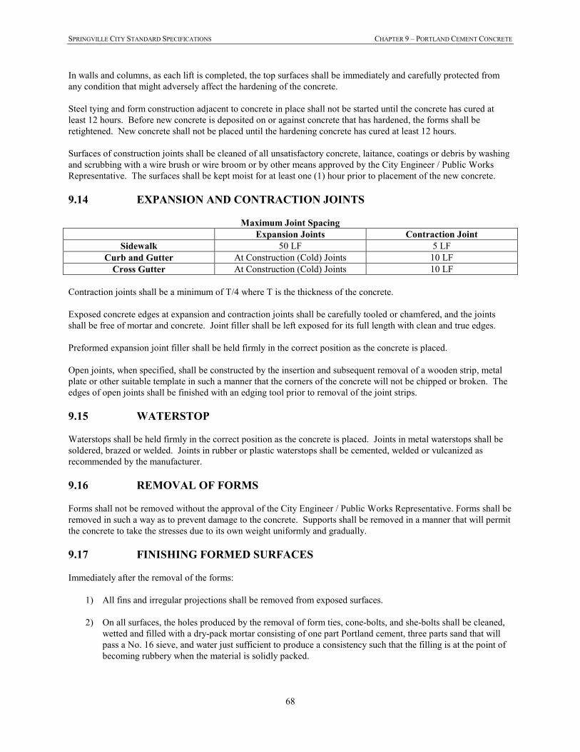
SPRINGVILLE CITY STANDARD SPECIFICATIONS CHAPTER 9 – PORTLAND CEMENT CONCRETE
68
In walls and columns, as each lift is completed, the top surfaces shall be immediately and carefully protected from
any condition that might adversely affect the hardening of the concrete.
Steel tying and form construction adjacent to concrete in place shall not be started until the concrete has cured at
least 12 hours. Before new concrete is deposited on or against concrete that has hardened, the forms shall be
retightened. New concrete shall not be placed until the hardening concrete has cured at least 12 hours.
Surfaces of construction joints shall be cleaned of all unsatisfactory concrete, laitance, coatings or debris by washing
and scrubbing with a wire brush or wire broom or by other means approved by the City Engineer / Public Works
Representative. The surfaces shall be kept moist for at least one (1) hour prior to placement of the new concrete.
9.14 EXPANSION AND CONTRACTION JOINTS
Maximum Joint Spacing
Expansion Joints Contraction Joint
Sidewalk 50 LF 5 LF
Curb and Gutter At Construction (Cold) Joints 10 LF
Cross Gutter At Construction (Cold) Joints 10 LF
Contraction joints shall be a minimum of T/4 where T is the thickness of the concrete.
Exposed concrete edges at expansion and contraction joints shall be carefully tooled or chamfered, and the joints
shall be free of mortar and concrete. Joint filler shall be left exposed for its full length with clean and true edges.
Preformed expansion joint filler shall be held firmly in the correct position as the concrete is placed.
Open joints, when specified, shall be constructed by the insertion and subsequent removal of a wooden strip, metal
plate or other suitable template in such a manner that the corners of the concrete will not be chipped or broken. The
edges of open joints shall be finished with an edging tool prior to removal of the joint strips.
9.15 WATERSTOP
Waterstops shall be held firmly in the correct position as the concrete is placed. Joints in metal waterstops shall be
soldered, brazed or welded. Joints in rubber or plastic waterstops shall be cemented, welded or vulcanized as
recommended by the manufacturer.
9.16 REMOVAL OF FORMS
Forms shall not be removed without the approval of the City Engineer / Public Works Representative. Forms shall be
removed in such a way as to prevent damage to the concrete. Supports shall be removed in a manner that will permit
the concrete to take the stresses due to its own weight uniformly and gradually.
9.17 FINISHING FORMED SURFACES
Immediately after the removal of the forms:
1) All fins and irregular projections shall be removed from exposed surfaces.
2) On all surfaces, the holes produced by the removal of form ties, cone-bolts, and she-bolts shall be cleaned,
wetted and filled with a dry-pack mortar consisting of one part Portland cement, three parts sand that will
pass a No. 16 sieve, and water just sufficient to produce a consistency such that the filling is at the point of
becoming rubbery when the material is solidly packed.
SPRINGVILLE CITY STANDARD SPECIFICATIONS CHAPTER 9 – PORTLAND CEMENT CONCRETE
69
9.18 FINISHING UNFORMED SURFACES
All exposed surfaces on the concrete shall be accurately screeded to grade and then float finished, unless specified
otherwise.
Excessive floating or troweling of surfaces while the concrete is soft will not be permitted.
The addition of dry cement or water to the surface of the screeded concrete to expedite finishing will not be allowed.
Joints and edges on unformed surfaces that will be exposed to view shall be chamfered or finished with molding
tools.
9.19 CURING AND PROTECTION
Concrete shall be prevented from drying for a curing period of at least 7 days after it is placed. Exposed surfaces
shall be kept continuously moist for the entire period, or until curing compound is applied as specified below.
Sprinkling, flooding or fog spraying shall maintain moisture or by covering with continuously moistened canvas,
cloth mats, straw, sand or other approved material. Wood forms (except plywood) left in place during the curing
period shall be kept wet. Formed surfaces shall be thoroughly wetted immediately after forms are removed and shall
be kept wet until patching and repairs are completed. Water or covering shall be applied in such a way that the
concrete surface is not eroded or otherwise damaged.
As soon as the concrete has hardened sufficiently to prevent damage, the finished surface shall be protected for
curing in one of the following ways:
1) Ponding of water on the surface or continuous sprinkling.
2) Application of absorptive mats such as three-inches (3") of cured hay, clean straw or fabric kept
continuously wet.
3) Application of two-inches (2") of moist earth or sand uniformly distributed on the surface and kept
saturated by spraying with water.
4) Application of light colored waterproof plastic materials, conforming to "Specifications for Waterproof
Sheet Materials for Curing Concrete" ASTM C171, placed and maintained in contact with the surface of the
concrete.
5) Application of a curing compound, conforming to "Specifications for Liquid Membrane - Forming
Compounds for Curing Concrete" ASTM C309. The compound shall be light in color and shall be applied
in accordance with the manufacturer’s recommendations immediately after any water sheen, which may
develop after finishing, has disappeared from the concrete surface.
Curing compound shall not be applied to surfaces requiring bond to subsequently placed concrete, such as
construction joints, shear plates, reinforcing steel and other embedded items. If the membrane is damaged during the
curing period, the damaged area shall be re-sprayed at the rate of application specified above.
9.20 REMOVAL OR REPAIR
When concrete is honey combed, damaged or otherwise defective, the Developer/Contractor shall remove and
replace the structure or structural member containing the defective concrete or, where feasible, correct or repair the
defective concrete. Prior to starting repair work the Developer/Contractor shall obtain the City Engineer / Public
Works Representative's approval of its plan for affecting the repair. The Developer/Contractor shall perform all
repair work in the presence of the City Engineer / Public Works Representative.
SPRINGVILLE CITY STANDARD SPECIFICATIONS CHAPTER 9 – PORTLAND CEMENT CONCRETE
70
9.21 CONCRETING IN COLD WEATHER
Concrete shall not be mixed nor placed when the daily minimum atmospheric temperature is less than 40° F unless
facilities are provided to prevent the concrete from freezing. (Below 25° F heating blankets alone will not be
allowed and must be supplemented with an additional heat source.) The use of accelerators or antifreeze compounds
will not be allowed. The contractor shall be responsible to insure the protection of the concrete regarding these
requirements.
9.22 CONCRETING IN HOT WEATHER
The Developer/Contractor shall apply effective means to maintain the temperature of the concrete below 90° F
during mixing, conveying and placing. The contractor shall be responsible to insure the protection of the concrete
regarding these requirements.
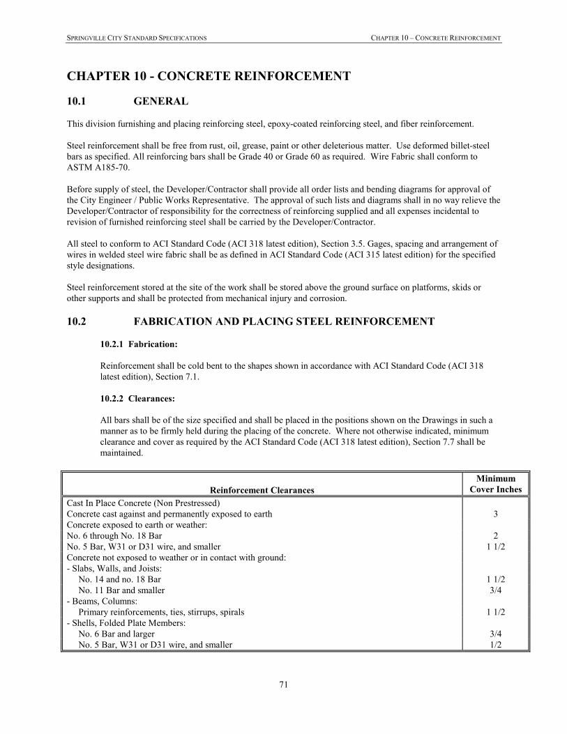
SPRINGVILLE CITY STANDARD SPECIFICATIONS CHAPTER 10 – CONCRETE REINFORCEMENT
71
CHAPTER 10 - CONCRETE REINFORCEMENT
10.1 GENERAL
This division furnishing and placing reinforcing steel, epoxy-coated reinforcing steel, and fiber reinforcement.
Steel reinforcement shall be free from rust, oil, grease, paint or other deleterious matter. Use deformed billet-steel
bars as specified. All reinforcing bars shall be Grade 40 or Grade 60 as required. Wire Fabric shall conform to
ASTM A185-70.
Before supply of steel, the Developer/Contractor shall provide all order lists and bending diagrams for approval of
the City Engineer / Public Works Representative. The approval of such lists and diagrams shall in no way relieve the
Developer/Contractor of responsibility for the correctness of reinforcing supplied and all expenses incidental to
revision of furnished reinforcing steel shall be carried by the Developer/Contractor.
All steel to conform to ACI Standard Code (ACI 318 latest edition), Section 3.5. Gages, spacing and arrangement of
wires in welded steel wire fabric shall be as defined in ACI Standard Code (ACI 315 latest edition) for the specified
style designations.
Steel reinforcement stored at the site of the work shall be stored above the ground surface on platforms, skids or
other supports and shall be protected from mechanical injury and corrosion.
10.2 FABRICATION AND PLACING STEEL REINFORCEMENT
10.2.1 Fabrication:
Reinforcement shall be cold bent to the shapes shown in accordance with ACI Standard Code (ACI 318
latest edition), Section 7.1.
10.2.2 Clearances:
All bars shall be of the size specified and shall be placed in the positions shown on the Drawings in such a
manner as to be firmly held during the placing of the concrete. Where not otherwise indicated, minimum
clearance and cover as required by the ACI Standard Code (ACI 318 latest edition), Section 7.7 shall be
maintained.
Reinforcement Clearances
Minimum
Cover Inches
Cast In Place Concrete (Non Prestressed)
Concrete cast against and permanently exposed to earth 3
Concrete exposed to earth or weather:
No. 6 through No. 18 Bar 2
No. 5 Bar, W31 or D31 wire, and smaller 1 1/2
Concrete not exposed to weather or in contact with ground:
- Slabs, Walls, and Joists:
No. 14 and no. 18 Bar 1 1/2
No. 11 Bar and smaller 3/4
- Beams, Columns:
Primary reinforcements, ties, stirrups, spirals 1 1/2
- Shells, Folded Plate Members:
No. 6 Bar and larger 3/4
No. 5 Bar, W31 or D31 wire, and smaller 1/2
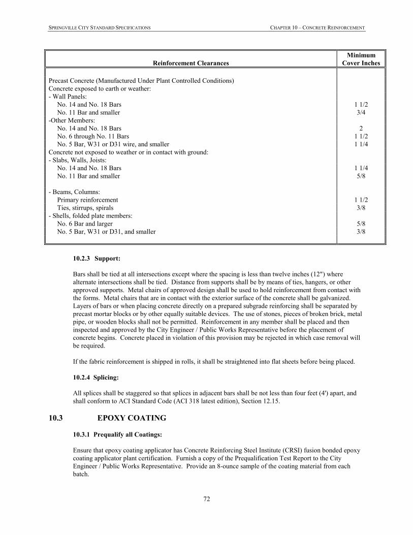
SPRINGVILLE CITY STANDARD SPECIFICATIONS CHAPTER 10 – CONCRETE REINFORCEMENT
72
Reinforcement Clearances
Minimum
Cover Inches
Precast Concrete (Manufactured Under Plant Controlled Conditions)
Concrete exposed to earth or weather:
- Wall Panels:
No. 14 and No. 18 Bars 1 1/2
No. 11 Bar and smaller 3/4
-Other Members:
No. 14 and No. 18 Bars 2
No. 6 through No. 11 Bars 1 1/2
No. 5 Bar, W31 or D31 wire, and smaller 1 1/4
Concrete not exposed to weather or in contact with ground:
- Slabs, Walls, Joists:
No. 14 and No. 18 Bars 1 1/4
No. 11 Bar and smaller 5/8
- Beams, Columns:
Primary reinforcement 1 1/2
Ties, stirrups, spirals 3/8
- Shells, folded plate members:
No. 6 Bar and larger 5/8
No. 5 Bar, W31 or D31, and smaller 3/8
10.2.3 Support:
Bars shall be tied at all intersections except where the spacing is less than twelve inches (12") where
alternate intersections shall be tied. Distance from supports shall be by means of ties, hangers, or other
approved supports. Metal chairs of approved design shall be used to hold reinforcement from contact with
the forms. Metal chairs that are in contact with the exterior surface of the concrete shall be galvanized.
Layers of bars or when placing concrete directly on a prepared subgrade reinforcing shall be separated by
precast mortar blocks or by other equally suitable devices. The use of stones, pieces of broken brick, metal
pipe, or wooden blocks shall not be permitted. Reinforcement in any member shall be placed and then
inspected and approved by the City Engineer / Public Works Representative before the placement of
concrete begins. Concrete placed in violation of this provision may be rejected in which case removal will
be required.
If the fabric reinforcement is shipped in rolls, it shall be straightened into flat sheets before being placed.
10.2.4 Splicing:
All splices shall be staggered so that splices in adjacent bars shall be not less than four feet (4') apart, and
shall conform to ACI Standard Code (ACI 318 latest edition), Section 12.15.
10.3 EPOXY COATING
10.3.1 Prequalify all Coatings:
Ensure that epoxy coating applicator has Concrete Reinforcing Steel Institute (CRSI) fusion bonded epoxy
coating applicator plant certification. Furnish a copy of the Prequalification Test Report to the City
Engineer / Public Works Representative. Provide an 8-ounce sample of the coating material from each
batch.
SPRINGVILLE CITY STANDARD SPECIFICATIONS CHAPTER 10 – CONCRETE REINFORCEMENT
73
10.3.2 Coat Bars as Specified:
The following requirements shall be followed:
1) Maintain the coating thickness between 8 and 12 mils.
2) Coat bars after bending, unless the fabricator can show that satisfactory results can be obtained by
coating before bending
3) Reject any bent bars with visible cracks or damage in the coating.
10.3.3 Handling:
Do not damage the bars or the coating during handling and storage.
1) Use systems with padded contact areas when handling coated bars.
2) Pad all bundling bands.
3) Lift all bundles with strong back, multiple supports, or a platform bridge.
4) Do not drop or drag bars.
5) Repair damaged bars or coating at no additional cost to the Owner.
6) Use patching material per manufacturer’s recommendation to repair damaged coating.
7) Have the coated bars inspected for damage to the coating after the bars are in place and immediately
before concrete placement.
8) Repair all visible defects using the specified patching or repair material.
10.4 FIELD CUTTING EPOXY-COATED BARS
10.4.1 Cutting:
Saw or shear epoxy-coated bars that are specified to be cut in the field. Do not flame cut.
10.4.2 Repairing:
Repair the sawed or sheared end using the specified patching or repair material.
10.5 FIBER REINFORCEMENT
Upon request by the City Engineer, cast-in-place concrete shall contain polypropylene fiber reinforcing with a fiber
length of 0.75 inches minimum and mixed at a rate of 1.5 pounds per cubic yard of concrete. The fibers shall be
introduced into the concrete mix at the time the concrete is batched in accordance with the manufacturer’s
recommendations. The required physical characteristics of the reinforcing fiber are as follows:
a) Specific Gravity 0.91
b) Tensile Strength 80-110 ksi
c) Fiber Length 0.75 inches (minimum)
The Developer/Contractor will submit documentation to the City Engineer and obtain approval of the fiber material
prior to use on the job.
SPRINGVILLE CITY STANDARD SPECIFICATIONS CHAPTER 11 – RESTORATION OF SURFACE IMPROVEMENTS
74
CHAPTER 11 - RESTORATION OF SURFACE IMPROVEMENTS
11.1 GENERAL
The Developer/Contractor shall be responsible for the protection and the restoration or replacement of any
improvements existing on public or private property at the start of work or placed there during the progress of the
work. Existing improvements shall include but not to be limited to permanent surfacing, striping, curbs, gutters,
sidewalks, driveways, planted areas, sprinkling systems, ditches, culverts, fences, walls, etc. All improvements shall
be reconstructed to equal or better, in all respects, than the existing improvements removed.
Developer/Contractor shall document existing improvements and conditions (video, photo, etc.) prior to
commencement of any construction activities. Where there are disputes regarding restoration of existing
improvements, the City will side with the private property owner if no documentation to the contrary can be provided
by the Developer/Contractor.
11.2 FIELD VERIFICATION OF IMPROVEMENTS
The Developer/Contractor shall carefully examine the site of the work and to acquaint itself with all conditions
relating to the protection and restoration of existing improvements. The City Engineer / Public Works Representative
does not guarantee that all improvements are shown on the Drawings, and it shall be the Developer/Contractor's
responsibility to protect and restore all existing improvements whether or not each is provided for specifically on the
Drawings.
11.3 REMOVAL OF PAVEMENT, SIDEWALKS, CURBS, ETC.
The pavement, sidewalk, curb and gutter, driveway, etc. shall be cut vertically along the limits of the improvements
to be removed, or nearest full joint, in such a manner as to not cause damage to adjoining pavement, sidewalk, curb
and gutter, driveway, etc. The portion to be removed shall be broken up in a manner that will not cause damage to
the pavement or concrete outside the limits of the improvements to be removed; however, any pavement damaged by
operations outside the limits of the work area shall be replaced at the Developer/Contractor's expense.
11.4 MATERIALS
Materials used for repair or replacement of surface improvements shall be equal to or better than the material
removed. All materials shall meet or exceed Springville City Standards and Specifications.
11.5 RESTORING BITUMINOUS OR CONCRETE STREET SURFACES
Where trenches are in or cross bituminous or concrete surfaced roads, traffic lanes, driveways, parking areas, etc.,
the bituminous or concrete surface shall be restored as quickly as there is sufficient quantity to make it practical
(weather permitting), and maintained as follows:
11.5.1 Before Excavation:
All existing asphalt or concrete surfaces shall be saw cut or roto-milled to a square edge before excavation.
11.5.2 Temporary Graded Surface:
Until resurfacing can be done in paved areas a temporary untreated base course surface shall be placed deep
enough to provide a minimum of eight inches (8") below the bottom of the bituminous surface and shall be
brought flush with the paved surface.
The untreated base shall be placed in the trench at the time it is backfilled. Excess material shall be removed
SPRINGVILLE CITY STANDARD SPECIFICATIONS CHAPTER 11 – RESTORATION OF SURFACE IMPROVEMENTS
75
from the premises immediately. The Developer/Contractor will maintain the temporary untreated base
course surface until the asphalt is placed.
11.5.3 Preparation for Paving:
The area over trenches to be resurfaced shall be graded to a smooth, uniform surface and compacted to not
less than 95% (maximum dry density). Mud or other soft or spongy material shall be removed and the void
filled with untreated base course and rolled and tamped thoroughly in layers not exceeding six inches in
thickness. The edges of trenches, which are broken down during the making of subgrade, shall be removed
and trimmed neatly before resurfacing.
Before any permanent resurfacing is placed, the Developer/Contractor shall trim the existing paving to
clean straight lines as nearly parallel to the centerline of the trench as practicable. Said straight lines shall be
established in thirty foot minimum lengths and no deviations from such lines shall be made except as
specifically permitted by the City Engineer / Public Works Representative.
Existing paving shall be saw-cut back a minimum of twelve inches (12”) beyond the limits of any
excavation or cave-in along the trench, creating a T-patch. The existing base material shall be removed in
the twelve inch (12”) cut back area and new road base material placed and compacted so that the edges of
the new trench paving will rest on a minimum of eight inches (8” depth) of newly placed and compacted
road base material (refer to the trench detail in the Standard Drawings). NOTE - the depth of base material
removed will need to be sufficient to allow for a minimum of four inches (4”) of pavement (or the existing
pavement thickness plus one inch whichever is greater), to be placed on a minimum of eight inches (8”) of
compacted road base.
The existing pavement from the edge of the newly created T-patch to the edge of asphalt / lip of gutter must
be a minimum of 30” wide and be undisturbed in order to remain in place. If this width is less than 30”, or
has been disturbed, then the Developer/Contractor shall be responsible to remove and replace the exist
asphalt.
A minimum of thirty (30) inches of existing undisturbed pavement is required between the edge of the
newly created T-patch and any structure, concrete, or edge of existing pavement surface. If less than thirty
(30) inches remains, the pavement shall be removed and permanent surfacing placed to the concrete or
structure. If more than 50% of the permanent surfacing of a traveled lane is impacted by the excavation, the
entire lane width will be required to be saw cut/milled, removed, and replaced to City standards. Trenching
or excavation is not permissible within eighteen (18) inches of any concrete or structure, unless permitted
by the City Engineer. Any surface or underlying pavement outside the trench which is undermined or
damaged by the trenching operation shall be removed to a neat, straight line, and replaced. In areas where
native, clean sands are present the City Engineer may require that trenching exceeding five (5) feet in depth
be required to remove and replace surfacing for a minimum of two (2) times the depth unless direct contact
shoring is provided to fully support the trench walls for full depth of the excavation.
11.5.4 Bituminous Surface:
The bituminous surface over trenches shall be restored by standard paving practices to a minimum thickness
of four inches (4") or match existing asphalt thickness plus one inch, whichever is greater. Gradation of
aggregate shall conform to the 1/2-inch gradation limits as defined in these Specifications, unless otherwise
approved by the City Engineer. Asphalt specifications to meet Section 12.8.
Pavement restoration shall include priming of pavement edges with Type MC-70 bituminous material and
placing rolled plant hot mix bituminous material to the level of the adjacent pavement surfaces.
11.5.5 Special Requirements for Longitudinal Trench Repair:
Trenching running parallel to the street (longitudinal) generally will have special mill and overlay repair
requirements. This will need to be coordinated with the City and constructed as specified in the
SPRINGVILLE CITY STANDARD SPECIFICATIONS CHAPTER 11 – RESTORATION OF SURFACE IMPROVEMENTS
76
“Excavation Permit” and as approved by the City Engineer.
11.6 UTILITY POTHOLES-KEYHOLE METHOD
This specification covers the requirements for keyhole coring, vacuum excavation, backfilling, and reinstatement of
the keyhole core in asphalt or concrete pavements to allow for underground utility repairs and underground
exploratory potholing. Keyhole coring shall be defined as follows: The operation of coring a circular hole through
the roadway pavement using diamond tipped core drilling equipment.
11.6.1 Pothole Excavation:
The vertical alignment of the keyhole coring shall be perpendicular to the horizon, and the cutting shall
extend to the full depth of the existing pavement section.
Unless otherwise approved by the Engineer, keyhole cores shall be no less than 6 –inches and no greater
than 18- inches in diameter. Adjacent cores shall not be closer than 3 feet from each other (edge to edge),
shall not contain a joint or any pavement cracks greater than 1/8-inch wide, and shall not be performed in
pavements where the section is less than 3-inches thick.
Coring shall be performed with a keyhole coring saw with high strength steel diamond tipped core drill bits.
The Contractor shall place a temporary mark on the keyhole core prior to cutting to insure that the removed
section is replaced in the same orientation as originally found in the pavement.
Soils within potholes shall be removed by air/vacuum extraction methods to expose utilities. The zone of
soil removal shall remain essentially within a vertical plane extending below the edges of the removed
pavement.
The Contractor shall remove all excess materials excavated from the site.
11.6.2 Pothole Backfill:
The Contractor shall use ½-sack CLSM as backfill in accordance with Chapter 16 – Flowable Fill (CLSM).
11.6.3 Bonding Agent:
The bonding agent is material required to bond asphalt pavement cores to the asphalt concrete pavement
from which it was originally removed. Bonding material shall be a single component cementitious, rapid
hardening, high strength, waterproof bonding agent conforming to the physical properties shown in Table-1
below.
TABLE-1
Bond Material Properties
Property ASTM Test Method Requirements
Bond Strength, psi (70 degrees F.,
30 minute cure) C882 200 min.
Compressive Strength, psi (70
degrees F, 60 min cure) C109 1500 min.
1) Bonding material shall be impervious to water penetration at the joint after curing.
2) Bonding material shall, within 30 minutes at minimum ambient temperature of 70 degrees F., allow an
18" diameter core to support a traffic load equivalent to at least three (3) times the AASHTO H-25
standard wheel load.
3) The bonding material is required to securely bond the asphalt concrete core to asphalt concrete
pavement and to fill all voids between the core and pavement and within the core.
SPRINGVILLE CITY STANDARD SPECIFICATIONS CHAPTER 11 – RESTORATION OF SURFACE IMPROVEMENTS
77
4) Specifications and test results for the bonding material shall be submitted to the City for review and
approval before use.
11.6.4 Pavement Restoration:
The surface cut by keyhole coring restored to its original condition with the reinstated core flush with and in
the original orientation as the existing surface, matching existing pavement surface appearance.
The bonding agent meeting the requirements of 11.6.3 shall be used for pavement core reinstatement.
Excess bonding material shall be removed from the restored surface. A patched appearance shall be
avoided in surface restoration wherever possible.
Unless otherwise approved by the Engineer, the Contractor shall reinstate the bonded keyhole core within
24 hours of cutting the pavement. Openings allowed to be left open greater than 24 hours shall be covered
with an approved steel road plate capable of supporting traffic loads. The steel plate must be rounded with a
fitted collar that, when inserted into the hole, will prevent the steel plate from tipping, tilting, bouncing or
spinning out of the hole under traffic conditions. An asphalt mix shall be used to ramp pavement up to the
steel plate along all edges.
Surface Tolerances: The reinstated core shall be flush and level with the adjacent pavement. Gaps
attributable to the positioning of the core shall be less than 1/16-inch between the bottom of a minimum 3-
foot long straightedge and the surface of the pavement in any direction on the surface of the keyhole core,
except across the pavement crown or drainage gutters.
11.6.5 Deficiencies:
Where the pavement core is found to be fractured or defective upon removal, or becomes damaged after
removal and prior to reinstating, the defective or damaged core shall not be used to reinstate the pavement.
Pavement repair shall be performed in accordance with Section 11.5.
A pavement core is considered unacceptable when one of the following conditions exist:
1) The core contains any vertical cracks wider than 1/8-inch extending full depth or partial depth through
the core; or
2) Any deteriorated piece of the core is larger than 10 percent of the overall area of the core.
3) Two or more successive layers of asphalt concrete in the core become horizontally delaminated and
cannot be rebounded to each other with the bonding compound.
All unacceptable pavement cores shall be removed from the job site.
If another equivalent core of sound condition and matching existing pavement of the same diameter, depth
and composition as the defective core is available, it may be reinstated in substitution of the defective core.
11.7 GRAVEL SURFACE
Where trenches are excavated through gravel-surfaced areas such as roads and shoulders, parking areas, unpaved
driveways, etc., the gravel surface shall be restored and maintained as follows:
11.7.1 Layer Thickness:
Place a minimum of six inches of compacted material.
11.7.2 Placement:
The material shall be placed in the trench at the time it is backfilled. The surface shall be maintained by
SPRINGVILLE CITY STANDARD SPECIFICATIONS CHAPTER 11 – RESTORATION OF SURFACE IMPROVEMENTS
78
blading, sprinkling, rolling, adding material, etc., to maintain a safe, uniform surface. Excess material shall
be removed from the premises immediately.
11.7.3 Gradation:
Material for use on gravel surfaces shall be road base obtained from sound, tough, durable gravel or rock
meeting the following requirements for gradation:
Passing 1-inch sieve 100%
Passing 1/2-inch sieve 79-91%
Passing No. 4 sieve 49-61%
Passing No. 16 sieve 27-35%
Passing No. 200 sieve 7-11%
11.8 MISCELLANEOUS IMPROVEMENTS
It shall be the Developer/Contractor's responsibility to restore to their original condition all irrigation canals, levees,
culverts, gates, fences, drainage ditches, and all such improvements, which are cut or disturbed during construction.
Topsoil in farming areas or along road edges shall be stored separate from subsoil during pipe trench excavation.
Topsoil shall be replaced during backfill operations as nearly as possible to its original condition, thereby assuring
suitable soil for reseeding.
11.9 RESTORATION OF SURFACES
Unless otherwise directed, all street surfacing, curbs, gutters, sidewalks, driveways, or other hard surface that must
be removed in the performance of the work shall be restored in kind by the Developer/Contractor in accordance with
the Specifications contained herein. Deviation of more than one-fourth inch (1/4") between old and new work or
within new construction shall be corrected. Such measurement shall be made from a ten-foot (10') minimum length
straight edge. Adjoining surfaces between old and new must be flush.
11.10 CLEANUP
At the completion of each area of work all equipment, barricades, and similar items shall be removed from the area.
All excess material will be removed. Adjacent borrow pits and road shoulders used for storage of excavating
materials will be smoothed and returned to their original condition.
11.11 PAVEMENT MARKINGS
The Developer/Contractor shall be responsible for restoration of pavement markings on all City and/or County
roadways. Restoration of pavement markings shall conform to the applicable local and state specifications.
On roadways under UDOT jurisdiction temporary pavement markings shall be provided for any removed or
obliterated markings. The temporary markings shall conform to UDOT standards and specifications. Permanent
pavement markings will be replaced by UDOT.
11.12 LANDSCAPE RESTORATION
Areas of new construction that cover or disturb existing landscaped areas with fills and cuts or areas disturbed by
construction of retaining walls shall have the landscape restored. Areas that have lawn or flower beds shall be
restored including sprinkling systems that might be damaged or relocated because of construction. Lawn covered or
removed shall be replaced by sod.
The topsoil shall be fertile, sandy loam topsoil, obtained from well-drained areas. It shall be without admixture of
subsoil or slag and shall be free of stones, lumps, sticks, plants or their roots, toxic substances or other extraneous
SPRINGVILLE CITY STANDARD SPECIFICATIONS CHAPTER 11 – RESTORATION OF SURFACE IMPROVEMENTS
79
matter that may be harmful to plant growth and would interfere with future maintenance. Topsoil pH range shall be
5.3 to 6.0.
The Contractor shall take a video of the construction area and perimeter thereof prior to commencing any
construction activities to document existing conditions of all areas adjacent to the construction site. A copy of this
video shall be made available to the City at the pre-constructions meeting and will be referred to ensure the
restoration of disturbed areas is equal to or better than prior to the construction.
SPRINGVILLE CITY STANDARD SPECIFICATIONS CHAPTER 12 – ROADWAY CONSTRUCTION
80
CHAPTER 12 - ROADWAY CONSTRUCTION
12.1 GENERAL
This Division covers roadway construction, including work consisting of pulverizing existing asphalt, earthwork and
roadway excavation. It also includes imported granular borrow, subgrade preparation, untreated base course, asphalt
surface and raising manholes and valve boxes to grade.
12.2 MILLING / PULVERIZING
The limits of the area to be milled / pulverized will be as shown on the improvement drawings. The existing asphalt
edges where the milling / pulverizing terminates shall be saw cut following or prior to being milled / pulverized.
Millings / Rap may only be used as granular borrow with approval of City Engineer.
When used as granular borrow, the Developer/Contractor shall pulverize the existing asphalt and road base to a
depth of 6 to 8 inches. The Developer/Contractor has the option of methods he feels will result in the least work and
best product in breaking up the existing asphalt, provided that the maximum size for a single piece of asphalt does
not exceed 3 inches. Placing, grading and compacting of this material shall comply with the requirements of borrow.
12.3 EARTHWORK
The earthwork needed for roadway construction shall meet the requirements of Chapter 8, Earthwork.
12.4 ROADWAY EXCAVATION
The roadway shall be excavated to the lines and grades shown on the improvements drawings or to the minimum
standard depths shown and/or described in these Standards and Drawings. All materials not meeting gradations and
specifications described herein shall be removed from the road section.
12.5 SUBGRADE PREPARATION
This work shall consist of the shaping and compacting of the subgrade in accordance with these specifications and in
conformity with the lines, grades, and typical cross sections shown on the Drawings or as established by the City
Engineer / Public Works Representative.
Following roadway excavation the existing subgrade shall be proof rolled by running moderate-weight rubber tire-
mounted construction equipment uniformly over the surface at least twice. During the rolling operation moisture
content of the subgrade layer shall be maintained at not less than 97% or more than 105% of the optimum moisture
content. Rolling shall be continued until the entire roadbed is compacted to the specified density to a minimum
depth of 8 inches.
It is the Developer/Contractor’s responsibility to stabilize the existing subgrade material by whatever means are
necessary to create a stable foundation upon which the roadway may be constructed. These means and methods must
be approved by the City Engineer / Public Works Representative prior to placement.
12.6 GRANULAR BORROW
Granular borrow (foundation or roadway) material shall consist of three-inch to four-inch (3”- 4”) well-graded
engineered fill meeting A-1-a, (AASHTO M 145 or ASTM D3282). Recycled concrete will not be allowed in the
public right-of-way.
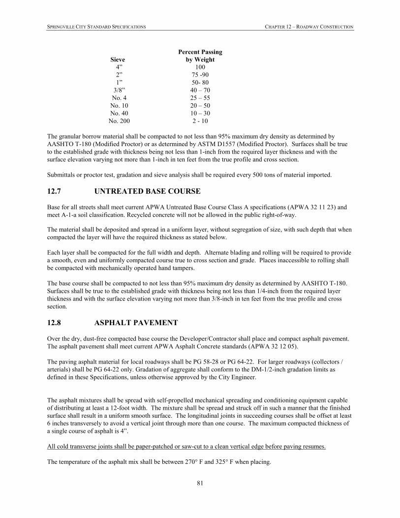
SPRINGVILLE CITY STANDARD SPECIFICATIONS CHAPTER 12 – ROADWAY CONSTRUCTION
81
Sieve
Percent Passing
by Weight
4” 100
2” 75 -90
1” 50- 80
3/8” 40 – 70
No. 4 25 – 55
No. 10 20 – 50
No. 40 10 – 30
No. 200 2 - 10
The granular borrow material shall be compacted to not less than 95% maximum dry density as determined by
AASHTO T-180 (Modified Proctor) or as determined by ASTM D1557 (Modified Proctor). Surfaces shall be true
to the established grade with thickness being not less than 1-inch from the required layer thickness and with the
surface elevation varying not more than 1-inch in ten feet from the true profile and cross section.
Submittals or proctor test, gradation and sieve analysis shall be required every 500 tons of material imported.
12.7 UNTREATED BASE COURSE
Base for all streets shall meet current APWA Untreated Base Course Class A specifications (APWA 32 11 23) and
meet A-1-a soil classification. Recycled concrete will not be allowed in the public right-of-way. The material shall be deposited and spread in a uniform layer, without segregation of size, with such depth that when
compacted the layer will have the required thickness as stated below.
Each layer shall be compacted for the full width and depth. Alternate blading and rolling will be required to provide
a smooth, even and uniformly compacted course true to cross section and grade. Places inaccessible to rolling shall
be compacted with mechanically operated hand tampers.
The base course shall be compacted to not less than 95% maximum dry density as determined by AASHTO T-180.
Surfaces shall be true to the established grade with thickness being not less than 1/4-inch from the required layer
thickness and with the surface elevation varying not more than 3/8-inch in ten feet from the true profile and cross
section.
12.8 ASPHALT PAVEMENT
Over the dry, dust-free compacted base course the Developer/Contractor shall place and compact asphalt pavement.
The asphalt pavement shall meet current APWA Asphalt Concrete standards (APWA 32 12 05).
The paving asphalt material for local roadways shall be PG 58-28 or PG 64-22. For larger roadways (collectors /
arterials) shall be PG 64-22 only. Gradation of aggregate shall conform to the DM-1/2-inch gradation limits as
defined in these Specifications, unless otherwise approved by the City Engineer.
The asphalt mixtures shall be spread with self-propelled mechanical spreading and conditioning equipment capable
of distributing at least a 12-foot width. The mixture shall be spread and struck off in such a manner that the finished
surface shall result in a uniform smooth surface. The longitudinal joints in succeeding courses shall be offset at least
6 inches transversely to avoid a vertical joint through more than one course. The maximum compacted thickness of
a single course of asphalt is 4”.
All cold transverse joints shall be paper-patched or saw-cut to a clean vertical edge before paving resumes.
The temperature of the asphalt mix shall be between 270° F and 325° F when placing.
SPRINGVILLE CITY STANDARD SPECIFICATIONS CHAPTER 12 – ROADWAY CONSTRUCTION
82
After the mixture has been spread, the surface shall be rolled in longitudinal direction commencing at the outside
edge or lower side and proceeding to the higher side. Each pass of the roller shall overlap the preceding pass at least
one-half the width of the roller. Rolling shall continue until 95% of the laboratory density as determined in
accordance with ASTM Designation D1559 for the asphalt mixture being used has been obtained. Density tests shall
be done following the procedures of ASTM D2950. Complete compaction before temperature drops to 180° F.
Rolling operations shall be conducted in such a manner that shoving or distortion will not develop beneath the roller.
The surface of the pavement, after compaction, shall be uniform and true to the established grade. When tested with
a ten-foot straight edge placed on the surface of the pavement, at any point, the surface shall not deviate more than
one-eighth of an inch from the lower edge of the straight edge. All high and low spots shall be remedied
immediately by removing the wearing course material over the affected areas and replacing it with fresh, hot wearing
course and surface finish material and immediately compacting it to conform with the surrounding area.
It is the responsibility of the Developer/Contractor to control traffic. Insofar as possible, all traffic shall be kept off
the completed surface for a minimum period of 24 hours.
No asphalt surface course shall be placed when the temperature of the roadbed is 45° F or below, during rainy
weather, when the base is wet, or during other unfavorable weather conditions as determined by the City Engineer /
Public Works Representative. The air temperature shall be 45° F and rising when measured in the shade.
A 2% minimum cross-slope and 4% maximum cross-slope is required. Any slopes higher or lower than the required
range must be approved by the City Engineer or designee.
12.9 ADJUSTING MANHOLES AND BOXES TO FINAL GRADE &
INSTALLING CONCRETE COLLAR
Covers shall be set to the finished grade and contour of the street. Rings and covers shall be protected during
backfilling and compaction of the road base and during the placing or replacing of road surfaces. Any rings or covers
damaged or broken shall be replaced by the Developer/Contractor at its expense. Prior to paving, the manhole ring
and cover shall be GPS-located by the Developer / Contractor (shot at the center of the ring) and set below the
finished road base elevation. After paving the asphalt shall be removed, and the manhole ring and cover shall be
raised to match the grade and slope of the finished road surface and shall use the WHIRLyGIG manhole riser/collar
system.
Road base around the manhole ring and cover shall be recompacted, and the concrete collar placed. Manholes and
boxes placed in asphalt surfacing shall be constructed such that the cast iron ring is one-quarter inch (1/4”) lower
than the pavement. The top of all concrete lids or cone sections shall be a minimum of eight inches (8”) and a
maximum of twelve-inches (12”) below the finished road surface. Manholes and boxes must be cleaned of all debris
after setting of collars.
12.10 ADJUSTING VALVE BOXES TO FINAL GRADE & INSTALLING
CONCRETE COLLAR
Valve boxes shall be set to the finished grade and contour of the street. Valve boxes shall be protected during
backfilling and compaction of the road base and during the placing or replacing of road surfaces. Any valve boxes
damaged or broken shall be replaced by the Developer/Contractor at its expense. Prior to paving, the valve box shall
be GPS-located by the Developer / Contractor (shot at the center of the valve box) and set six (6) inches below the
finished grade. After paving the asphalt shall be removed, and the valve box shall be raised to match the grade and
slope of the finished road surface.
Road base around the valve box shall be re-compacted, and the concrete collar placed. Valve boxes placed in
asphalt surfacing shall be constructed such that the cast iron ring is one-quarter inch (1/4”) lower than the pavement.
Valve boxes must be cleaned of all debris after setting of collars.
SPRINGVILLE CITY STANDARD SPECIFICATIONS CHAPTER 12 – ROADWAY CONSTRUCTION
83
SPRINGVILLE CITY STANDARD SPECIFICATIONS CHAPTER 13 – CONCRETE PLACEMENT
84
CHAPTER 13 - CONCRETE PLACEMENT
13.1 GENERAL
This section covers installation of curb and gutter and all concrete flatwork. All improvements shall be constructed to
the dimensions and thickness shown on the Standard Drawings.
13.2 CONCRETE
See Chapter 9, Portland Cement Concrete.
13.3 GRADE
After construction, gutters shall be checked by flowing water. The City Engineer / Public Works Representative
shall be present during the flow test. Any high spots or depressions (which exceed 0.02 feet) shall be repaired by
removing concrete and replacing to the correct grade. Puddling shall not flow from flow line past lip of gutter.
(Minimum flow line grade shall be 0.5 percent.)
13.4 FORMS
All forms shall be steel, except at curves with a radius smaller than 200 feet. They shall be of a size to match the
sections shown on the Drawings. Forms shall be held firmly in place with stakes or other approved means and shall
be true to line and grade.
All forms shall be clean and coated with a light oil to prevent the concrete from adhering to them. Clamps, spreaders
and braces shall be used where required to insure rigidity in the forms.
Forms shall not vary from vertical grade by more than 0.02 feet and from horizontal alignment by more than 0.05
feet. All forms shall have smooth even lines in both the horizontal and vertical plane.
Forms for curved sections shall be so constructed and placed that the finish surface of walls and edge of sidewalks,
curbs and gutters will not deviate from the arc of the curve.
13.5 SUBGRADE PREPARATION
The Developer/Contractor shall grade to the line and grade approved by the City. The sub-grade shall be properly
shaped to conform with the cross section shown on the Standard Drawings, graded and compacted. Compaction
shall meet the requirements of Division 7 Earthwork.
All excess material excavated by the Developer/Contractor shall be removed from the site. Removal of the
excavated material shall be done before or immediately after the concrete is placed. The Developer/Contractor shall
maintain adequate barricades and other devices to protect the public until excavated material is removed.
Placement of concrete on unsuitable materials shall not be permitted. The subgrade surface shall have a road base
foundation as shown on the Standard Drawings. Immediately prior to the placing of concrete, the subgrade shall be
compacted to at least 95% of the maximum dry density as determined by AASHTO T-180 (Modified Proctor).
13.6 CONSTRUCTION OF CURB, GUTTER AND SIDEWALK
Concrete for curb and gutter or sidewalks may be placed using stationary forms or the slip method of forming.
SPRINGVILLE CITY STANDARD SPECIFICATIONS CHAPTER 13 – CONCRETE PLACEMENT
85
13.6.1 Matching Existing Monolithic Curb, Gutter and Sidewalk
When matching an existing condition of combination curb, gutter and sidewalk the following construction
methods shall be used: Concrete curb, gutter and sidewalk shall be constructed by first constructing the
curb and gutter and then constructing the sidewalk behind it. Stationary forms may be used to place
combination curb, gutter and sidewalk. The slip form method may be used if it can be demonstrated that the
tolerances specified herein can be met.
13.6.2 Curb and Gutter Joints
Curb and gutter shall have contraction joints placed every 10 feet by use of 1/8-inch steel template of the
exact cross section of the curb and gutter. Remove the templates as the concrete takes initial set. Cut the
joint 1-1/2 inches deep when using the slip form method to place the concrete. Use 1/2-inch thick, pre-
molded, expansion joint filler at all cold joints unless otherwise specified by the City Engineer / Public
Works Representative.
13.6.3 Sidewalk Joints
Sidewalks shall have contraction joints at 5-foot intervals. The joints shall be approximately 3/16 inch wide
and approximately one-half of the total slab thickness in depth.
Expansion joints shall be 1/2-inch thick, shall be placed every 50 feet minimum, and at all cold joints.
Material for expansion joints shall be as specified in AASHTO M-153 and AASHTO M-213, and shall be
installed with its top approximately 1/4-inch below the concrete surface.
13.6.4 Finishing of Sidewalks
After the concrete placed for a sidewalk has been brought to the established grade and screeded, it shall be
float finished, edged and then given a light broom finish. In no case shall dry cement or a mixture of dry
cement and sand be sprinkled on the surface to absorb moisture or hasten hardening. Surface edges of all
slabs shall be rounded to a radius of 1/2 inch.
13.6.5 Finishing of Curb and Gutter
After concrete has been placed in curb and gutter forms, it shall be consolidated so as to insure a thorough
mixture, eliminate air pockets, and create uniform, smooth sides. As the concrete takes its initial set the
forms shall be removed and all exposed surfaces shall be float finished, edged and broomed lightly. The
curb and gutter shall be constructed to the dimensions shown in the Standard Drawings.
The top and face of the curb and also the top of the apron on combination curb and gutter must be finished
true to line and grade and without any noticeable irregularities of surface. No portion of the surface or face
of the curb and gutter shall depart more than 1/4 inch from a straight edge ten feet in length, placed on the
curb parallel to the street center line nor shall any part of the exposed surface present a wavy appearance.
13.7 CONCRETE DRIVE APPROACH
The concrete to be used for the drive approach shall be Class AA(AE) and shall meet the requirements of Chapter 9,
Portland Cement Concrete.
The approach shall be of the minimum thickness and constructed to the dimensions shown on the Standard
Drawings. The concrete shall be finished as described above for sidewalks.
The approach shall have a compacted untreated base course under them as shown on the standard drawings.
SPRINGVILLE CITY STANDARD SPECIFICATIONS CHAPTER 13 – CONCRETE PLACEMENT
86
13.8 ADA (AMERICANS WITH DISABILITIES ACT) STANDARDS IN
PUBLIC RIGHTS-OF-WAY
All construction shall conform to the current Federal American With Disabilities Act (ADA) guidelines for public
rights-of-way, and in accordance to the City’s Standard Drawings.
SPRINGVILLE CITY STANDARD SPECIFICATIONS CHAPTER 14 – UDOT RIGHTS-OF-WAY
87
CHAPTER 14 - UTAH DEPARTMENT OF TRANSPORTATION RIGHTS-
OF-WAY
14.1 GENERAL
The Developer/Contractor shall be responsible to obtain all necessary permits and meet any bond requirements imposed
by the Utah Department of Transportation for all work to be performed within UDOT rights-of-way.
A copy of the approved permit(s) shall be submitted to the City prior to commencing any work within the UDOT right-
of-way within Springville City limits.
SPRINGVILLE CITY STANDARD SPECIFICATIONS CHAPTER 15 – CASINGS
88
CHAPTER 15 - CASINGS
15.1 GENERAL
This division defines the requirements for casings under canals, railroad tracks, highways and interstates. All
construction operations shall be subject to the approval of the canal company, Railroad Company, or the Utah
Department of Transportation whose facilities are being crossed.
The Developer/Contractor shall be responsible to make application to and obtain all necessary permits and meet any
bond requirements imposed by the entity whose facility is to be crossed. A copy of the approved permit(s) shall be
submitted to the City prior to commencing any work within the right-of-way within Springville City limits.
The Developer/Contractor shall provide all insurance and the services of all watchmen and flagmen required by the
entity whose facility is to be crossed. The Developer/Contractor will pay entity whose facilities are to be crossed for
their inspection services.
SPRINGVILLE CITY STANDARD SPECIFICATIONS CHAPTER 16 – FLOWABLE FILL (CLSM)
89
CHAPTER 16 - FLOWABLE FILL (CLSM)
16.1 GENERAL
Meet the requirements of APWA SECTION 31 05 15 CEMENT TREATED FILL.