Embed Size (px)
Citation preview
ENGINEER MANUAL EM 1110-3-135April 1984
ENGINEERING AND DESIGN
STANDARD PRACTICE FORCONCRETE PAVEMENTS
MOBILIZATION CONSTRUCTION
DEPARTMENT OF THE ARMY~~
CORPS OF ENGINEERS .
OFFICE OF THE CHIEF OF ENGINEERS
DAEN-ECE-G
Engineer Marual No. 1110-3-135
DEP AR.TMENT OF THE ARMY U.S. Army Corps of Engineers
Washington, D.C. 20314
Engineering and Design STANDARD PRACTICE FOR CONCRETE PAVEMENTS
Mobilization Construction
EM 1110-3-135
9 April 1984
1. Purpose. This marual provides information for the investigation of concrete materials, proportioning, and construction of concrete pavements at u.s. Army mobilization facilities.
2. Applicability. This marual is applicable to all field operating activities having mobilization construction responsibilities.
3. Discussion. Criteria and standards presented herein apply to construction considered crucial to a mobilization effort. These requirements may be altered when necessary to satisfy special conditions on the basis of good engineering practice consistent with the nature of the construction. Design and construction of mobilization facilities must be completed within 180 days from the date notice to proceed is given with the projected life expectancy of five years. Hence, rapid construction of a facility should be reflected in its design. Time-consuming methods and procedures, normally preferred over quicker methods for better quality, should be de-emphasized. Lesser grade materials should be EU bsti tuted for higher grade materials when the lesser grade materials would provide satisfactory service and when use of higher grade materials would extend construction time. Work items not immediately necessary for the adequate functioning of the facility should be deferred until EUch time as they can be completed without delaying the mobilization effort.
FOR THE CO~IMANDER:
,/- _ .. ,/// /~ ~(:t·L< .. / /' 1._;:, , :i""-JC-:'<r :
PAUL F ~ , KAVANAUGH ·1
Coloqei, Corps of Engineers Chief of Staff
Engineer Manual No. 1110-3-135
DEPARTMENT OF THE ARMY U. S. Army Corps of Engineers
Washington, D. C. 20314
Engineering and Design STANDARD PRACTICE FOR CONCRETE PAVEMENTS
Mobilization Construction
EM 1110-3-135
9 April 1984
Paragraph Page
CHAPTER 1.
CHAPTER 2.
CHAPTER 3.
CHAPTER 4.
CHAPTER 5.
GENERAL
Purpose and scope . ................. . Strength and air content •...•..•...• Water •.••••••••••••••••.•••••.•••••• Admixtures ......................... . Cement ••••...••••...•••..••••••••••• Delivery and storage of
materials ......................... . Pavement protection ••.••..•••••...••
AGGREGATES
Options ............................ . Sources . ........................... . Coarse aggregate ............•....... Fine aggregate •....•.••••.•..••••••. Aggregate for calibration
bards tands ........................ .
SAMPLING AND TESTING
Cement ••••.••.••••...••••.•••••••••• Aggregates ......................... . Field test specimens •.•.••.•...•••••
PROPORTIONING
Mixture proportioning ••...•.••••••.• Mixture proportions •.•.••••..•.••••• Workability ........................ . Strength ........................... .
BATCHING AND MIXING
General . ........................... . Capacity of plant •••..•.••••••••.••• Concrete m1xers ...•.•...•..••••.•••• Approval of mixers •.•••...••..•.•.••
i
1-1 1-2 1-3 1-4 1-5
1-6 1-7
2-1 2-2 2-3 2-4
2-5
3-1 3-2 3-3
4-1 4-2 4-3 4-4
5-1 5-2 5-3 5-4
1-1 1-1 1-2 1-2 1-3
1-3 1-3
2-1 2-1 2-1 2-3
2-4
3-1 3-1 3-1
4-1 4-1 4-1 4-1
5-1 5-1 5-1 5-1
EM 1110-3-135 9 Apr 84
CHAPTER 6.
CHAPTER 7.
CHAPTER 8.
CHAPTER 9.
CHAPTER 10.
Paragraph Page
Transporting ready-mix concrete .......................... . 5-5 5-1
SUBGRADE, BASE, FORMS, AND STRIN·G LINES
General ............................ . Subgrade definition •..•..••••..•..•• Form materials ..................... . Placement of forms and string
1 i ne s ............................. . String line ........................ . Remova 1 of forms ••.....•.••.••••.•••
PLACING
General ............................ . Placing time . ...................... . Slip-form paving •.••••.••..•.••.•... Spreading .......................... . Vibration .......................... . Surface vibrators ..•..•....•••.••... Steel reinforcement •..•.•••...••••.. Placing during cold weather •..•...•• Placing during hot weather .••••..•.• Placing of small areas ..•.•••••.•... Overlay-pavement
construction ...................... .
FINISHING AND CURING
Finishing .......................... . Curing .. ........................... .
TOLERANCES
Grade and surface-smoothness req ui remen t s ...................... .
Tolerances in pavement thickness •..••.•••..•••..••.•••••..
JOINTS
General ........••.•..•.•.•.......... Construction joints .••..••.....•..•. Expansion joints ..•••..•••.•••...•.• Contraction joints .•..••....•••.•••.
l.l.
6-1 6-2 6-3
6-4 6-5 6-6
7-1 7-2 7-3 7-4 7-5 7-6 7-7 7-8 7-9 7-10
7-11
8-1 8-2
9-1
9-2
10-1 10-2 10-3 10-4
6-1 6-1 6-1
6-1 6-1 6-2
7-1 7-1 7-1 7-1 7-1 7-2 7-2 7-2 7-2 7-3
7-3
8-1 8-1
9-1
9-1
10-1 10-1 10-2 10-2
CHAPTER 11.
APPENDIX A.
Table 2-1. 2-2. 2-3. 2-4. 2-5. 9-1.
EM 1110-3-135 9 Apr 84
Paragraph Page
THIN BONDED RIGID OVERLAYS FOR RIGID PAVEMENTS
General ••.•..••••••••••••••••••••••• 11-1 11-1 Correction of defects in existing pavement •.•••..•••••••••••
Flexural strength .•••.••••••••.••••• Aggregate sizes ......••••••.•••••... Cement •••••••••.•.•.•••.•••••••••••• Conditioning of existing
11-2 11-3 11-4 11-5
ll-1 11-1 11-1 11-2
pavements.......................... 11-6 11-2
REFERENCES
LIST OF TABLES
Coarse aggregate size groups. Grading of coarse aggregate. Deleterious substances in coarse aggregate. Grading of fine aggregate. Deleterious substances in fine aggregate. Surface smoothness - airfield and heliport pavements.
iii
A-1
CHAPTER 1
GENERAL
EM 1110-3-135 9 Apr 84
J-1. Purpose and scope. This manual provides information for the investigation of concrete materials, proportioning, and construction of concrete pavements at Army mobilization facilities.
1-2. Strength and air content.
a. Responsibility for mixture proportioning. The responsibility for mixture proportioning will be assigned to the Contractor, and the Contracting Officer will approve the quality of all concrete materials used in the mixture. The Contractor will control all proportions of the concr.ete mixture necessary to obtain the strength and quality of the concrete required for the pavements.
b. Flexural strength. Airfield pavement and road pavement structural designs are based on flexural strengths that the concrete is expected to obtain at the ages of 90 and 28 days, respectively. However, due to the nature of the construction, a 7-day strength will be specified for control of the concrete mixture in the field. This strength requires that a reliable correlation be established at the ages of 7 days and 28 or 90 days for the concrete mixture to be used in road or airfield pavement construction, respectively. Flexural strength for all concrete pavements will be a minimum of 650 psi.
c. Test specimens. Flexural strength tests will be made on molded beam specimens of 6- by 6-inch cross-sectional dimensions in accordance with ASTM C 78. Standardization of the test specimen is necessary because of variations in the flexural strength obtained with specimens of different sizes. It is essential that the 6- by 6-inch molded beam specimen be used for all flexural strength determinations, in both laboratory and field.
d. Air content.
(1) Effects on air entrainment. Air-entrained concrete will be required for all concrete pavements. Air entrainment improves the workability and placing characteristics of freshly mixed concrete and increases the freezing-and-thawing resistance of hardened concrete. Some reduction in flexural strength, however, will usually result, nearly proportional to the percentage of air entrained in the concrete. Proper proportioning and control of the air-entrained concrete mixture are essential in order to derive maximum benefits from improvement in the placeability and durability of concrete with a minimum reduction in flexural strength.
(2) Percentage of air content. The specified air content will be 6 plus or minus 1-1/2 percent for concrete pavements located in
1-1
EM 1110-3-135 9 Apr 84
regions where resistance to freezing and thawing is a prime consideration, and 5 plus or minus 1-1/2 percent for concrete pavements located in regions where frost action is not a factor and air entrainment is used primarily to improve the workability and placeability of freshly mixed concrete. Air content will be controlled in the field at the point within the specified range most appropriate for local conditions, depending upon the severity of exposure and the quality and maximum size of aggregate.
e. Cement content. A cement content of at least 470 pounds per cubic yard will be required for proposed roadways and runways. Cement content will be increased as necessary to achieve the minimum flexural strength.
1-3. Water. Water for mixing concrete will be free from materials that affect hydration of the cement. Potable water may be used without testing; however, tests will be made if the water source is a stream or another body of water of unknown quality.
1-4. Admixtures.
a. Air-entraining admixtures. The air-entraining admixtures used will be based on the necessary assurance that the proposed admixture will have no effects on the properties of the concrete other than those desired by the air entrainment. The admixture will be prepared in a solution for addition at the mixer and batched with the mixing water. When truck mixers are permitted, and it is impractical to add the air-entraining admixture with the water, addition of the admixture solution with the fine aggregate is permissible.
b. Other admixtures. specified or approved for Contracting Officer.
Only accelerators and retarders may be use in concrete without prior approval of the
(1) Calcium chloride. In some instances, it may be desirable to require or permit the use of calcium chloride in concrete placed during cold weather in order to accelerate the set and thus permit the finishing and protection of the concrete without undue delay.
(2) Retarders. The use of a retarder should be considered when concrete is to be placed at temperatures exceeding 85 degrees F. or when problems in finishing are anticipated. The Contractor has the option of using a retarder for concrete temperatures of 85 degrees F. or below.
(3) Pozzolans. Fly ash or raw or calcined natural pozzolan may be used as part of the cementitious material up to 25 percent of the solid volume of portland cement plus pozzolan.
1-2
EM 1110-3-135 9 Apr 84
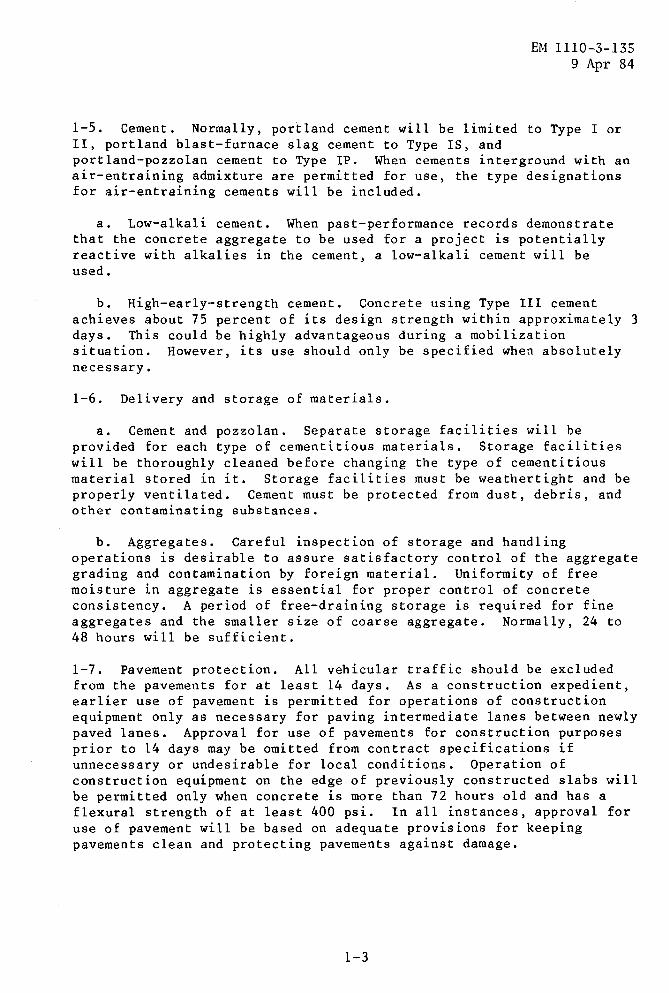
1-5. Cement. Normally, portland cement will be limited to Type I or II, portland blast-furnace slag cement to Type IS, and portland-pozzolan cement to Type IP. When cements interground with an air-entraining admixture are permitted for use, the type designations for air-entraining cements will be included.
a. Low-alkali cement. When past-performance records demonstrate that the concrete aggregate to be used for a project is potentially reactive with alkalies in the cement, a low-alkali cement will be used.
b. High-early-strength cement. Concrete using Type III cement achieves about 75 percent of its design strength within approximately 3 days. This could be highly advantageous during a mobilization situation. However, its use should only be specified when absolutely necessary.
1-6. Delivery and storage of materials.
a. Cement and pozzolan. Separate storage facilities will be provided for each type of cementitious materials. Storage facilities will be thoroughly cleaned before changing the type of cementitious material stored in it. Storage facilities must be weathertight and be properly ventilated. Cement must be protected from dust, debris, and other contaminating substances.
b. Aggregates. Careful inspection of storage and handling operations is desirable to assure satisfactory control of the aggregate grading and contamination by foreign material. Uniformity of free moisture in aggregate is essential for proper control of concrete consistency. A period of free-draining storage is required for fine aggregates and the smaller size of coarse aggregate. Normally, 24 to 48 hours will be sufficient.
1-7. Pavement protection. All vehicular traffic should be excluded from the pavements for at least 14 days. As a construction expedient, earlier use of pavement is permitted for operations of construction equipment only as necessary for paving intermediate lanes between newly paved lanes. Approval for use of pavements for construction purposes prior to 14 days may be omitted from contract specifications if unnecessary or undesirable for local conditions. Operation of construction equipment on the edge of previously constructed slabs will be permitted only when concrete is more than 72 hours old and has a flexural strength of at least 400 psi. In all instances, approval for use of pavement will be based on adequate provisions for keeping pavements clean and protecting pavements against damage.
1-3
CHAPTER 2
AGGREGATES
EM 1110-3-135 9 Apr 84
2-1. Options. Materials for concrete paving may be crushed or uncrushed gravel, crushed stone, crushed blast-furnace slag, or recycled crushed PCC pavement for coarse aggregate; or natural or manufactured sand for fine aggregate.
2-2. Sources. Aggregate material should be sought in the area or vicinity of the project. Distant sources could incur transportation problems since freight train or long distance trucking would be required. The advice of local suppliers, contractors, or engineers should be sought to evaluate the optimal source of concrete aggregates.
2-3. Coarse aggregate.
a. Composition. The crushing of gravel or stone tends to improve quality and bond characteristics and generally results in a higher flexural strength of concrete. When mixture proportioning studies or local experience indicates that a low flexural strength will be obtained with uncrushed gravel or stone, the possibility of obtaining higher strength by crushing the material will be investigated.
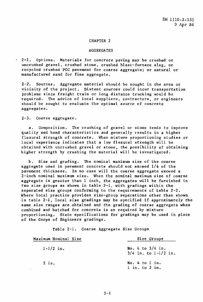
b. Size and grading. The nominal maximum size of the coarse aggregate used in pavement concrete should not exceed 1/4 of the pavement thickness. In no case will the coat:se aggregate exceed a 2-inch nominal maximum size. When the nominal maximum size of coarse aggregate is greater than 1 inch, the aggregates will be furnished in two size groups as shown in table 2-1, with gradings within the separated size groups conforming to the requirements of table 2-2. Where local practice provides size-group separations other than shown in table 2-1, local size gradings may be specified if approximately the same size ranges are obtained and the grading of coarse aggregate when combined and hatched for concrete is as required by mixture proportioning. State specifications for gradings may be used in place of the Corps of Engineers gradings.
Table 2-1. Coarse Aggregate Size Groups
Maximum Nominal Size Size Groups
1-1/2 ln • No. 4 to 3/4 in. 3/4 in. to 1-1/2 in.
2 ln. No. 4 to 1 in. 1 in. to 2 in.
2-1
EM 1110-3-135 9 Apr 84
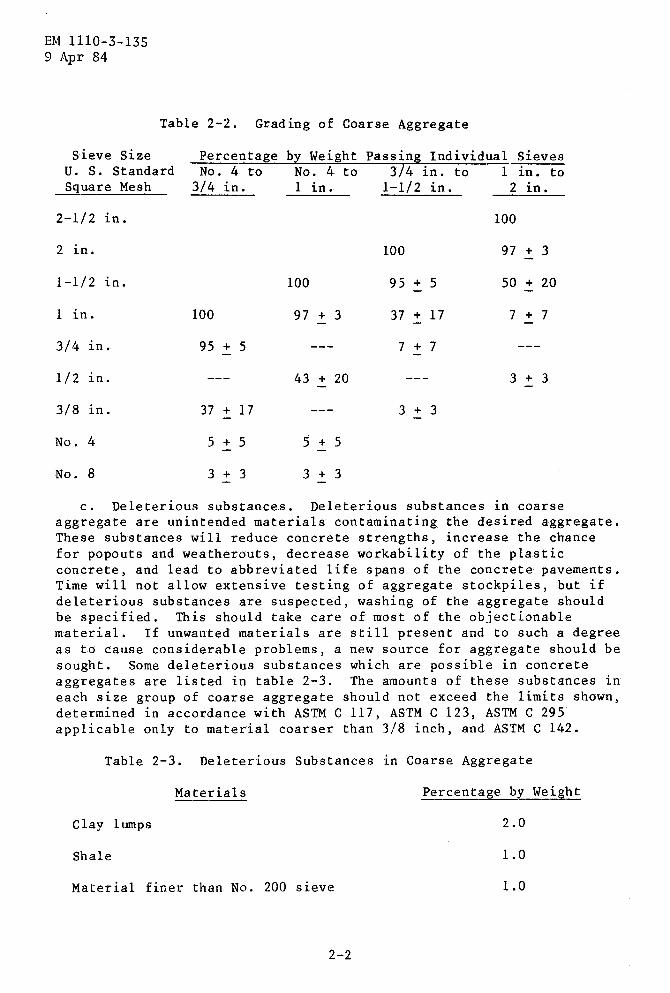
Table 2-2. Grading of Coarse Aggregate
Sieve Size Percentage b~ Weight Passing Individual Sieves u. s. Standard No. 4 to No. 4 to 3/4 in. to 1 in. to Square Mesh 3/4 in. 1 l.n. 1-1/2 in. 2 in.
2-1/2 in. 100
2 in. 100 97 + 3
1-1/2 in. 100 95 + 5 50 + 20
1 in. 100 97 + 3 37 + 17 7 + 7
3/4 l.n. 95 + 5 7 + 7
1/2 1n. 43 + 20 3 + 3
3/8 1n. 37 + 17 3 + 3
No. 4 5 + 5 5 + 5
No. 8 3 + 3 3 + 3
c. Deleterious substances. Deleterious substances in coarse aggregate are unintended materials contaminating the desired aggregate. These substances will reduce concrete strengths, increase the chance for popouts and weatherouts, decrease workability of the plastic concrete, and lead to abbreviated life spans of the concrete pavements. Time will not allow extensive testing of aggregate stockpiles, but if deleterious substances are suspected, washing of the aggregate should be specified. This should take care of most of the objectionable material. If unwanted materials are still present and to such a degree as to cause considerable problems, a new source for aggregate should be sought. Some deleterious substances which are possible in concrete aggregates are listed in table 2-3. The amounts of these substances in each size group of coarse aggregate should not exceed the limits shown, determined in accordance with ASTM C 117, ASTM C 123, ASTM C 295 applicable only to material coarser than 3/8 inch, and ASTM C 142.
Table 2-3. Deleterious Substances 1.n Coarse Aggregate
Materials Percentage by Weight
Clay lumps 2.0
Shale 1.0
Material finer than No. 200 sieve 1.0
2-2
EM 1110-p-135 9 Apr 84
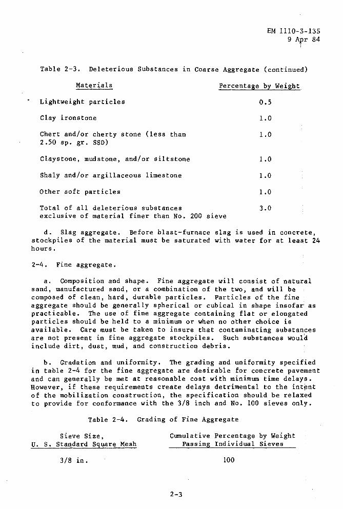
Table 2-3. Deleterious Substances in Coarse Aggregate (continued)
Materials Percentage by Weight
Lightweight particles
Clay ironstone
Chert and/or cherty stone (less than 2.50 sp. gr. SSD)
Claystone, mudstone, and/or siltstone
Shaly and/or argillaceous limestone
Other soft particles
Total of all deleterious substances exclusive of material finer than No. 200 sieve
0.5
1.0
1.0
1.0
1.0
1.0
3.0
d. Slag aggregate. Before blast-furnace slag is used in concr~te, stockpiles of the material must be saturated with water for at lea~t 24 hours.
2-4. Fine aggregate.
a. Composition and shape. Fine aggregate will consist of natu~al sand, manufactured sand, or a combination of the two, and will be composed of clean, hard, durable particles. Particles of the fine aggregate should be generally spherical or cubical in shape insofar as practicable. The use of fine aggregate containing flat or elongated particles should be held to a minimum or when no other choice is available. Care must be taken to insure that contaminating substances are not present in fine aggregate stockpiles. Such substances would include dirt, dust, mud, and construction debris.
b. Gradation and uniformity. The grading and uniformity specified 1n table 2-4 for the fine aggregate are desirable for concrete pavement and can generally be met at reasonable cost with minimum time delays. However, if these requirements create delays detrimental to the intent of the mobilization construction, the specification should be relaxed to provide for conformance with the 3/8 inch and No. 100 sieves only.
Table 2-4.
Sieve Size, U. s. Standard Square Mesh
3/8 in.
Grading of Fine Aggregate
Cumulative Percentage by Weight Passing Individual Sieves
100
2-3
EM 1110-3-135 9 Apr 84
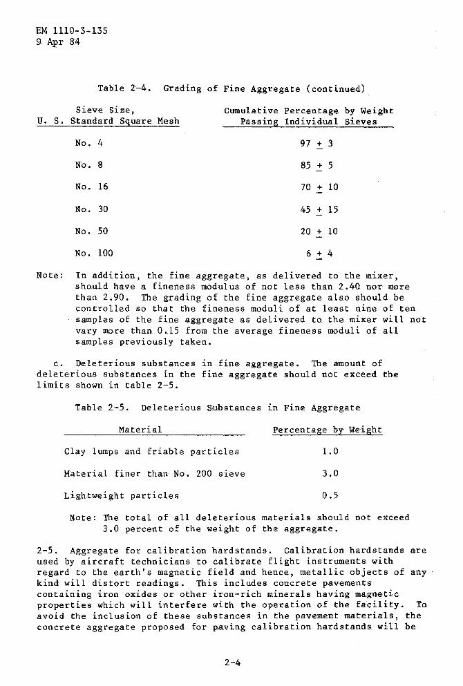
Table 2-4. Grading of Fine Aggregate (continued)
Sieve Size, Cumulative Percentage by W.eight u. s. Standard Square Mesh Passing Individual Sieves
No. 4 97 + 3
No. 8 85 + 5
No. 16 70 + 10
No. 30 45 + 15
No. 50 20 + 10
No. 100 6 + 4
Note: In addition, the fine aggregate, as delivered to the mixer, should have a fineness modulus of not less than 2.40 nor m0re than 2.90. The grading of the fine aggregate also should be controlled so that the fineness moduli of at least nine of ten samples of the fine aggregate as delivered to the mixer will not vary more than 0.15 from the average fineness moduli of all samples previously taken.
c. Deleterious substances in fine aggregate. The amount of deleterious substances in the fine aggregate should not exceed the limits shown in table 2-5.
Table 2-5. Deleterious Substances 1n Fine Aggregate
Material Percentage by Weight
Clay lumps and friable particles 1.0
Material finer than No. 200 sieve 3.0
Lightweight particles 0.5
Note: The total of all deleterious materials should not exceed 3.0 percent of the weight of the aggregate.
2-5. Aggregate for calibration hardstands. Calibration hardstands are used by aircraft technicians to calibrate flight instruments. with regard to the earth's magnetic field and hence, metallic objects of any kind will distort readings. This includes concrete pavements containing iron oxides or other iron-rich minerals having magnetic properties which will interfere with the operation of the facility. To avoid the inclusion of these substances in the pavement materials, the concrete aggregate proposed for paving calibration hardstands will be
2-4

EM 1110-3-135 9 Apr 84
subjected to petrographic analyses (ASTM C 295) prior to acceptance. Special attention will be given to the existence of magnetite in granites, high-iron minerals in traprock, pyrite in limestone, and free iron or iron oxide in slag aggregate.
2-5
CHAPTER 3
SAMPLING AND TESTING
EM 1110-3-135 9 Apr 84
• 3-1. Cement. Cement for mobilization pavement projects may be accepted on the basis of the manufacturer's certified mill tests reports showing compliance with cited cement specifications. Cement will be sampled and tested only when there is reason to believe it does not meet the specifications.
3-2. Aggregates. Aggregate sources will be based on an investig~tion to determine the suitability of available aggregates for the proposed use. In general, existing approved sources should be used and new sources should be avoided as much as possible. Otherwise, evaluation of the material will require laboratory testing, including petrographic examinations, physical tests, durability tests, and alkali-reactivity tests which are time consuming. The service record of the aggregates will be determined by inspecting structures that have had exposure equivalent to the proposed structure. When an aggregate source has been approved previously for use on the basis of a complete investigation, additional similar use of the source may be permitted if there is no change evident in the composition and quality of aggregate.
3-3. Field test spec~mens.
a. General. Field tests other than those called for by Contr4ctor quality control will be conducted by the Government to determine the slump and air content of freshly mixed concrete, and specimens will be molded to test for flexural strength of hardened concrete. Since the Contractor will be required to furnish concrete samples, labor, and facilities for molding and curing test specimens, it is necessary that specifications indicate the extent of testing required. Equipment for making air-content and slump tests will be furnished by the Contracting Officer when the Government is responsible for testing and by the Contractor when the Contractor is responsible for testing. Beam molds will be made of steel, rigid and watertight. Beam molds will be supplied by the Contracting Officer, except when the Contractor is responsible for testing. When molds are required to be furnished by the Contractor, details necessary to assure that molds furnished are satisfactory will be included in the contract specifications.
b. Specimens for strength tests. Test specimens for determining the conformance with specified strength requirements will be moist-cured under field-laboratory conditions. The size and number of curing tanks will depend on the number of specimens taken and the ages at which the tests are made. For airfield paving projects, flexural-strength tests will be conducted at the ages of 7, 28, amd 90 days. For other pavements, designed on the basis of 28-day flexural strengths, the test ages will be 7 and 28 days. Where 90-day
3-1
EM 1110-3:;-135 9 Apr 84
flexural-stTength tests are required, provisions will be made for the curing and testing of sp.ecimens after the project is completed.
3-2
CHAPTER 4
PROPORTIONING
EM 1110-3-135 9 Apr 84
4-1. Mixture proportioning. Before any concrete 1s placed, the Contractor will present a mix design which will give the required flexural strength. In addition, this design should demonstrate that water-cement ratio, air content, and workability are within specified requirement ranges. Based on this mix, 6 by 6 inch test specimens should be made, cured, and tested in accordance with standard procedures to establish the flexural strength of this concrete. Enough test specimens should be made to provide for three tests at 7 days, three at 28 days, and three at 90 days for airfield and three tests at 7 days and three tests at 28 days for roads.
4-2. Mixture proportions. The Contracting Officer will require such changes in the mixture proportions as necessary to maintain the workability, strength, and quality required by the contract specifications. The mixture proportions determined by initial testing will be used in starting paving operations. Adjustments will be made by the Contractor as necessary to establish the mixture proportions best suited for job conditions and materials used. Subsequent mixture adjustments will be made when necessary, but usually they are of a minor nature as required to compensate for variations in gradings and the moisture content of the aggregate.
4-3. Workability. The concrete slump will not exceed 2 inches. Within this maximum limit, the slump will be maintained at the lowest practical value suitable for prevailing weather conditions and for equipment and methods used in placement of the concrete. For small paved areas where vibration is not required, a slump in excess of 2 inches may be permitted, but in no case will the slump exceed 4 inches. Slump for slip-form paving of airfield and heliport pavements should be specified in a range of 1/2 to 1-1/2 inches.
4-4. Strength. Control of the strength of the concrete mixture will be based on tests of concrete specimens taken during the paving operations. Pavements to be used by aircraft are designed on the basis of the flexural strength that the concrete is expected to attain at the age of 90 days, and specimens will be tested at this age for use in the evaluation of pavements. Since the period necessary to obtain the 90-day field strengths is too great to exercise proper control of the concrete during pavement construction, a 28-day strength requirement will be included in the contract specifications. Flexural-strength tests will be made at the age of 28 days to determine compliance with the 28-day strength requirement. In addition, 7-day strength tests will be made to provide an early indication of the concrete strength. The average strength at the age of 28 days of any five consecutive individual test values representing each concrete mixture will be not less than the specified strength at the age of 28 days, and not more
4-1

EM 1110-3-135 9 Apr 84
than 20 perc.ent of the individual values will be less than the specified strength. Adjustments of the concrete mixture propcrtions will be made as necessary to maintain this strength control.
4-2
CHAPTER 5
BATCHING AND MIXING
EM 1110~3-135 9 Apr 84
.5-l. General. Standard minimum requirements for hatching and m1x1ng of concrete cover three types of plants: automatic, semiautomatic, and manual. For paving projects, either automatic or semiautomatic plants will be acceptable. Specifications will be prepared to allow either type of plant, and the Contractor will have the option as to the type of plant to be used. ·
S-2. Capacity of plant. The capacity to be specified for the hatching plant and mixing equipment will be determined in accordance with the concrete-placement requirements for the project. Since the pavememt slabs are comparatively small, the plant capacity generally will not be influenced by any requirements for maintaining the concrete in a plastic condition during placement. The main considerations will be the required placing schedule to meet the completion date for the construction or, when slip-form pavers are used, the required amount of concrete to maintain a uniform forward movement of the paver of not less than 2.5 fpm. However, the placement rate specified for pavements constructed during hot weather should also be considered in determining plant capacity requirements.
5-3. Concrete mixers. Mixers having a capacity of at least 5 cubic yards of mixed concrete are required for airfield paving projects, ;but smaller mixers may be permitted for small road projects and other small miscellaneous construction.
5-4. Approval of mixers. Before truck mixers or stationary mixers are approved for use, careful consideration will be given to the proposed plant and facilities for storage and handling of materials, and for hatching, mixing, transporting, and handling of concrete at the job site to assure that adequate control of the concrete can be exercised. When truck mixers are used with a long haul between the hatching pl~nt and the project, adequate control of the concrete may be difficult due to variations in slump and air content caused by differences in mixing time. In such cases, it will be necessary to require that mixing be done after the mixer trucks arrive on the job. Truck mixers will be equipped with accurate revolution counters.
5-5. Transporting ready-mix concrete. Central-mixed concrete may be transported in a truck agitator, in a truck mixer operating at agitating speed, or in approved nonagitating equipment. Nonagitating equipment will have smooth, watertight, metal bodies equipped with gates to permit control of the discharge of the concrete; covers will be provided for protecting concrete in transit, as required. Concr~te transported in nonagitating equipment will be discharged into the pavement forms within 45 minutes after the introduction of the miximg water to the cement and aggregates at the mixer. The major problem in
5-l
EM 1110~3-135 9 Apr 84
using ready-mixed concrete in pavement construction is to avoid segregation of the granular materials in discharging and transferring the concrete from the transporting unit to the final position in the form or on the subgrade in front of the slip-form paver. The use of ready-mixed concrete will require the use of suitable transfer and spreading equipment capable of depositing and distributing the concrete in an unsegregated condition in the final position in the forms. When low slump mixed concrete is transported, trucks equipped with vibrators are often required to discharge the concrete and should be required unless it is satisfactorily demonstrated that the concrete can be discharged without delay.
5-2
CHAPTER 6
SUBGRADE, BASE, FORMS, AND STRING LINES
EM 1110-'3-135 9 Apr 84
·6-1. General. The setting and protection of forms and string lines and the final preparation of the subgrade, base course, or filter course require close attention to all details to assure that the pavement will have the required thickness and the surface will be at the required grade.
6-2. Subgrade definition. For concrete paving work, the term "subgrade" generally has been used to indicate material directly underneath the concrete pavement regardless of type. However, in some instances, subgrade has been interpreted to indicate only natural earth material and not other materials used as a base or a filter course. In order to avoid a misunderstanding, project plans and specifications in all instances will indicate the specific type of material required, such as subgrade, subbase, base course, or filter course. The lime, cement, or asphalt-stabilized material immediately under the pavement will be considered as the base course.
6-3. Form materials. Wood forms generally are unsatisfactory for paving work, and their use will be discouraged except for such miscellaneous areas as bulkheads and curved fillets. To avoid the excessive cost of pavement construction for small jobs, wood forms may be allowed for pavements less than 8 inches thick in noncritical areas. These would include open storage areas, helicopter parking pads, and vehicle parking. Steel forms are needed for spreading and finishing equipment.
6-4. Placement of forms and string lines. Forms and string lines should be installed well in advance of concrete paving operations s1o that the required checks and necessary corrections can be made with1out stopping or hindering concrete placement. The same reasoning applies to the final preparation of the underlying material, which should n,ot be less than 1 full day's operation of the paving equipment ahead oif paving.
6-5. String line. The string line should be of high-strength cord' or wire. The choice will depend on the type of automatically controlled fine grader or slip-form paver used~ Certain manufacturers recommend that high tensile-strength wire be stretched tautly between supports. Other manufacturers recommend a large diameter cord and do not require the tautness that is recommended for wire. The use of wire requires firmly anchored supports. As a result, wire is less likely to be disturbed than is cord whose supports do not have to be so firmly anchored. Wire is difficult to see, and flagging should be attached between the supports to reduce the chance that it will be disturbed during construction. Cord does not require supports to be as firmly anchored as for wire, and as a result, cord is easier to install and
6-1
EM 1110-3-135 9 Apr 84
maintain. However, the chance of sagging between the supports is greater. Cord is easy to see, and as a result, the chances of it getting out of alinement are less than for wire. However, cord is more easily disturbed than wire and should be checked more frequently.
6-6. Removal of forms. Pavement forms generally may be removed 12 hours after the concrete is placed. A longer period will be necessary when the strength gain of the concrete is retarded because of delayed or inadequate protection during cold weather. In some instances, it will be desirable to permit earlier removal of forms so that the transverse joints may be sawed completely through to the edge of the slab without leaving a small fillet of concrete adjacent to the form.
6-2
CHAPTER 7
PLACING
EM 1110.:..3-135 9 Apr 84
·7-1. General. Concrete may be placed between fixed forms, or it may be placed using approved slip-form paving equipment. Both methods produce satisfactory results, and when pass ible, the option should. be left with the Contractor as to the method to be used. With slip-fprm equipment, the rate of placement can be significantly increased over the rate with fixed forms. In addition, the material for forms and the labor for setting forms are eliminated. As a result, the cost for large jobs will be less for slip-form placement than for placement with fixed forms. However, on small jobs or larger jobs with special requirements, the use of fixed forms may be necessary or more economical than the use of slip-form equipment. No guidelines can be given as to what size job will permit the economic use of slip-form pavers since the choice will depend on what equipment local contractors have available.
7-2. Placing time. Concrete will be placed before obtaining its initial set and within 45 minutes after water has been added to the batch. These provisions apply to all paving projects regardless o~ the type of mixing equipment used. The addition of water to the mixtute 1n excess of that required by the mixture proportions to maintain slump during prolonged mixing will not be permitted.
7-3. Slip-form paving. Approval of the slip-form paving equipment for airfield pavement will be based on satisfactory performance in the field. Trial sections of sufficient length and located in low-volume aircraft traffic areas will be used to approve the paving equipment, considering both slip form and another for the fill-in operation when scheduled by the Contractor. Furthermore, approval will be based on the ability of the machine to consolidate the concrete and form th¢ pavement to the desired cross sections. Plan grade and surface smoothness tolerances must be met. Particular attention should be paid to the ability of the machine to form the required edge without excessive slumping or tearing during slip-form operations and to form a suitable longitudinal construction joint during fill-in operations. The machine will not damage the surface or edge of the previously placed slab during fill-in operations. The suggested length of the trial section is 1,000 to 2,000 feet.
7-4. Spreading. Hand spreading of concrete will be permitted only when necessitated by odd widths or shapes of slabs, or in emergencies such as equipment breakdown.
7-5. Vibration. Vibration requirements are influenced by many factors, such as the type and size of aggregate, mixture proportio~s, air entrainment, slump, workability of mixture, and pavement thickmess. The specified maximum spacing for vibrator units and the specified
7-1
EM 1110-3-135 9 Apr 84
vibrating procedures are based on field experience with the vibration of pavements 12 or more inches in thickness. There has been only limited use of internal vibration for thinner slabs. If necessary for proper consolidation of the concrete, a closer spacing of vibrator units will be required. General experience has been that it is more satisfactory to use vibrators at a closer spacing and for shorter periods of vibration than to attempt to consolidate the concrete by prolonged vibration at a wider spacing. The duration of the vibration will be limited by the time necessary to produce a satisfactory consolidation of the concrete, and overvibration will not be permitted. Vibrators must not be permitted to touch forms, dowels, tie bars, or other embedded items.
7-6. Surface vibrators. Surface vibrators will not be permitted as past experience with them generally has been unsatisfactory.
7-7. Steel reinforcement. Project drawings will show typical details of all slab reinforcement and will indicate the pavements requiring reinforcement and the location and amount of steel required in the slabs. This information will supplement the specification requirements for reinforcement, and all requirements will be carefully checked to insure there are no discrepancies between drawings and specification requirements.
7-8. Placing during cold weather. It is seldom desirable to place pavement concrete when the air temperature is below 40 degrees F., and special provisions for placement and protection of the concrete are necessary for such construction. For additional information on winter concreting, refer to ACI 306R. The necessary covers and other means of protecting the concrete during cold weather should be available on the job before starting concrete placement. Calcium chloride as an admixture may be either required or approved to accelerate the setting time of concrete placed during cold weather. No changes will be made in the requirements for temperature of the concrete when placing or for protection of the concrete against freezing when calcium chloride or any other accelerator is used.
7-9. Placing during hot weather. During hot weather, special precautions are necessary to prevent the formation of plastic-shrinkage cracks, which result from an excessive loss of moisture from the concrete before positive curing has begun. The concrete will be placed at the coolest temperature practicable, and in no case will the temperature of the concrete as placed exceed 90 degrees F. Mixing and placing of concrete will be so controlled as to keep moisture loss at a minimum. Aggregates will be moist when added to the mixer, and the subgrade dampened so it will not absorb water from the concrete. The concrete temperature may be reduced by using cement having a temperature below the maximum 150 degrees F. specified, by sprinkling the stockpiles of aggregate to produce cooling by evaporation, by precooling mixing water, or by avoiding delays in mixing and placing
7-2
EM 1110-3-135 9 Apr 84
concrete. The concrete will be placed and finished as rapidly as practicable, and the curing started without delay. If the application of the curing medium should, for any reason, lag placement for a time sufficient to permit surface drying, the surface should be kept damp
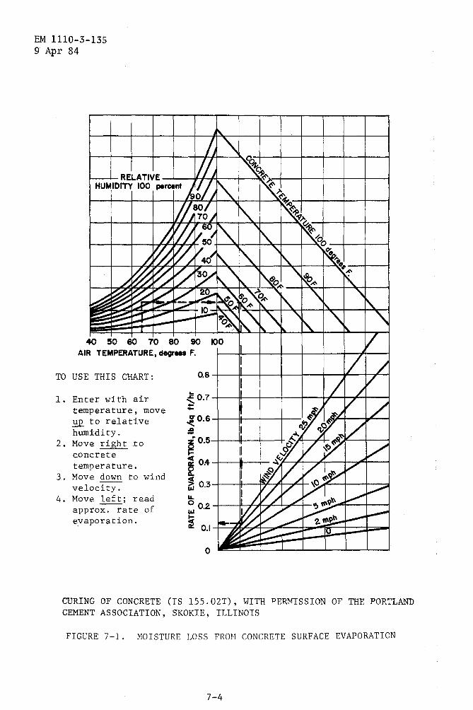
.with a fog spray and placement should be discontinued until corrective action can be taken. The fog spray equipment will be capable of applying a very fine mist to the concrete to replace moisture lost'by evaporation. In windy areas, screens may be needed to protect the concrete from rapid evaporation caused by wind. Curing methods will assure that an evaporation rate of 0.2 psf per hour as shown in fi~ure 7-1 is not exceeded.
7-10. Placing of small areas. For vehicular parking and paving projects of 1,200 cubic yards or less, machine spreading, finishin~, and floating will not be required if the benefits derived from the use of the equipment are not commensurate with the cost of using the machines. In this case, hand spreading, finishing, and floating w~ll be specified.
7-11. Overlay-pavement construction. Where overlay-pavement construction is required, contract specifications will contain provisions for preparation and treatment of the existing surface before placing concrete in the overlay pavement. Criteria herein pertain ·to construction of rigid overlays on existing ~igid pavement. Construction of rigid overlays on existing flexible pavement or an existing rigid pavement with a bond breaking course is treated as n•ew construction.
a. Bond between layers of pavement. Overlay pavements general!~ are designed on the assumption that a partial bond will develop between the two concrete layers. Concrete surfaces to receive partially bopded overlays will be thoroughly cleaned of dirt and other foreign material, loose or spalled concrete, extruding joint seal, bituminous patches!, and material that would break the bond between the concrete layers. Different areas of pavement will require different treatment. The condition of the existing pavement will determine the cleanup measures necessary. Normally, sandblasting or surface-abrading equipment wi11 be required to remove material adhering to the surface, and hand scaling of loose or spalled material will be required. No special treatment, such as acid wash of the prepared surface or the use of a grout bonding course, will be required for partially bonded overlays. In areas where oil or grease is present on the surface, scrubbing with a detergent and a wire brush may be required. Cleaning of surfaces.to receive the overlay with rotary grinding equipment will be permitted, but the surface must be swept clean prior to placing the concrete overlay.
b. Control of cracking in overlay pavement. Considerable difficulty has been experienced with uncontrolled cracking of overlay pavements at contraction joints. This cracking is likely to occur
7-3
EM 1110-3-135 9 Apr 84
TO
1.
2.
3.
4.
" h " RELATIVE //, ~~ HUMIDITY 100 percent Js'{~
"" ~ 90 ) ~
,ff/~t, ~
~ ~~~ ~01:1 ~ '1\. ~00
~Vh~/~ ~ 1\. '\~ , .. ~~~~;!Y ~"
'\ ,.,~
i\. !\eo~ ~~ '\.
~ ~ ~ v s: ~ ~6'o '\o~ 'I\. '\ '\
t\. :..t"'" 17'" ~
OAIK_~ " ~ ~ ~ ~--"""" ~ ~ .'\ '\ ~ '\ '\ - - r"\. i'\. " " 40
AIR 50 60 10 80 90 100 /
USE
Ent tern ~ hum Mov con tern Mov vel Mov app eva
TEMPERATURE, degrees F. I / /
THIS CHART: 0.8 I I v
/ er with air ~0.7 .. t ~v v
/ / perature, move -to relative ~0.6 ~~ v idity. :£! I
~0.5 ~..1.. ~
e right .to I ~~~/~ / crete <
perature. ~ 0.4 ~ ~//~~ v
e down to wind ~ 0.3 --
ocity. 'J ~/Vi ~
e left; read ... ~ 0 02 / / '!>~9'r< rox. rate of 1&.1 •
~ ~~~ ~ poration. t( ~ a: 0.1 r-"""7
~~t:::;::~ ll
0 I
CURING OF CONCRETE (IS 155.02T), WITH PERMISSION OF THE PORTLAND CEMENT ASSOCIATION, SKOKIE, ILLINOIS
FIGURE 7-1. MOISTURE LOSS FROM CONCRETE SURFACE EVAPORATION
7-4
EM 1110-3-135 9 Apt 84
during hot weather when the temperature of existing pavement is appreciably higher than that of the concrete being placed in the overlay. Contraction due to cooling of base pavement results in movement at the existing joint, which may start a crack in the bottom of the overlay as the concrete hardens. This cracking may occur wh¢n the concrete is too green to saw. Often the crack is not visible at the surface of the pavement when the sawing is done. To prevent such cracking, it may be necessary to use filler-type joints.
7-5
CHAPTER 8
FINISHING AND CURING
8-1. Finishing.
EM 1110-3~135 9 Ap~ 84
a. Equipment and methods. Types of finishing equipment other than conventional equipment may be used on a trial basis when capable of finishing concrete of the quality and consistency required •
. b. Surface finishing and testing. Finishing operations are pointed toward obtaining a dense, smooth surface true to the required grade. Since the surface receives the greatest exposure to weathering and traffic, every precaution will be taken to obtain a high-quality concrete at the surface. The finishing operations will be kept to the m1n1mum necessary to obtain the required surface finish. Excessive surface manipulation will not be permitted as it tends to bring a surplus of mortar, water, and undesirable soft materials to the surface, which contributes to scaling and surface deterioration. Finishing should leave the surface at the proper grade. If the mechanical finishing operations are properly controlled, very little hand finishing will be necessary. Short floats will be used only as necessary to correct local surface unevenness. Straightedges of the required length will be used primarily to smooth and check the surface. To avoid later costly corrections of hardened pavement, which fails td conform with specific surface tolerances, the surface will be thoroughly checked during the mechanical floating and necessary corrections will be made.
c. Hand finishing and edging. Machine finishing is required, but hand finishing will be permitted for odd widths and shapes of slabs, areas adjacent to headers, and areas around outlets in the pavements. Hand-finished areas will have the same quality and the same surface characteristics as those areas finished by machine.
d. Surface texture. The final suface texture of the pavement will be provided by means of a burlap drag, wire comb, or broom.
8-2. Curing.
a. Control of cracking. Shrinkage (craze) cracking is caused by 4 combination of high ambient air temperature, high concrete temperatur~, low relative humidity, and wind velocity. These conditions need to be controlled when placing and protecting young concrete. It is essential that concrete be protected against loss of moisture and rapid temperature change for the specified period of protection. Equipment, material, and supplies for adequate curing and protection of the concrete must be on hand and ready to install before actual concrete placement begins. In general, curing will be accomplished by using a
8-1
EM 1110-3-135 9 Apr 84
membrane curing compound. However, other methods may be specified if indicated by local conditions.
b. Membrane curing. The curing compound will be applied by means of a power-driven machine straddling the newly paved lane and operated so that the spray will cover the pavement surface completely and uniformly. Spray nozzles should be surrounded by a hood to prevent wind from blowing the curing-compound spray. The rate of advance ~f the spraying machine will be controlled so that a two-coat overlapping coverage will be provided. Hand-operated pressure sprayers will be permitted only on indicated odd widths and shapes of slabs and on concrete surfaces exposed by removal or forms or when machines are not available. The curing compound must form a continuous void-free membrane and be maintained in this condition throughout the curing period. Unsatisfactory or damaged areas will be resprayed. Any damage to the membrane during the sawing operation will be corrected by respraying.
c. Substitute curing provisions. Where it has been established from past experience in an area that membrane curing alone does not adequately protect pavement from shrinkage cracking, a combination of moist curing and membrane curing may be specified.
d. Selection of curing material for pavements to be painted. In selecting curing material for pavement surfaces to be painted, consideration will be given to the necessity of sandblasting to remove coatings and deposits that interfere with the bonding of paint. Curing compounds of the low-melting-point wax-base type tend to penetrate concrete and should not be used in the areas to be painted.
8-2
CHAPTER 9
TOLERANCES
9-1. Grade and surface-smoothness requirements.
EM 1110-$-135 9 Apr 84
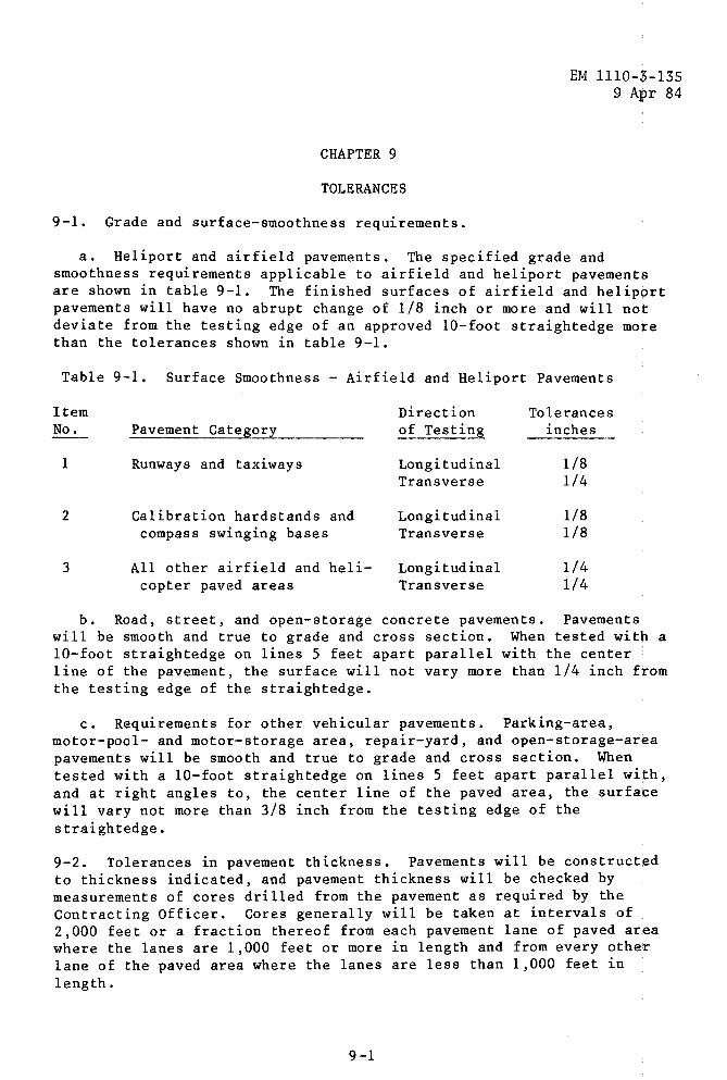
a. Heliport and airfield pavements. The specified grade and smoothness requirements applicable to airfield and heliport pavements are shown in table 9-1. The finished surfaces of airfield and heliport pavements will have no abrupt change of 1/8 inch or more and will not deviate from the testing edge of an approved 10-foot straightedge more than the tolerances shown in table 9-1.
Table 9-1. Surface Smoothness -Airfield and Heliport Pavements
Item Direction Tolerances No. Pavement Category of Testing inches
1 Runways and taxiways Longitudinal 1/8 Transverse 1/4
2 Calibration hardstands and Longitudinal 1/8 compass swinging bases Transverse 1/8
3 All other airfield and heli- Longitudinal 1/4 copter paved areas Transverse 1/4
b. Road, street, and open-storage concrete pavements. Pavements will be smooth and true to grade and cross section. When tested with a 10-foot straightedge on lines 5 feet apart parallel with the center line of the pavement, the surface will not vary more than 1/4 inch from the testing edge of the straightedge.
c. Requirements for other vehicular pavements. Parking-area, motor-pool- and motor-storage area, repair-yard, and open-storage-area pavements will be smooth and true to grade and cross section. When tested with a 10-foot straightedge on lines 5 feet apart parallel with, and at right angles to, the center line of the paved area, the surface will vary not more than 3/8 inch from the testing edge of the straightedge.
9-2. Tolerances in pavement thickness. Pavements will be constructed to thickness indicated, and pavement thickness will be checked by measurements of cores drilled from the pavement as required by the Contracting Officer. Cores generally will be taken at intervals of 2,000 feet or a fraction thereof from each pavement lane of paved area where the lanes are 1,000 feet or more in length and from every other lane of the paved area where the lanes are less than 1,000 feet in length.
9-1
CHAPTER 10
JOINTS
EM 1110-3-135 9 Apr 84
!0-1. General. Joints are constructed in concrete pavements to permit contraction and expansion of pavement without irregular cracking and as a construction expedient to separate the paved area into strips necessary for the handling and placing of concrete. There are three general types of joints: construction, contraction, and expansion.
10-2. Construction joints.
a. Longitudinal construction joints. These joints formed betwe~n paving lanes at the spacing indicated will be either thickened edge, keyed, keyed and tied, or doweled, as indicated. The keyed joint is critical insofar as dimensions are concerned. It is essential that both key dimensions and location of key in the joint conform with the design requirements. Key dimensions are based on pavement thickness, each thickness requiring a different key size. When stationary forms are used, metal molds for forming the keyway will be securely fastened to the concrete forms so that molds will not be displaced by paving operations. When slip-form pavers are used to form keyed joints, the keyway will be formed by means of preformed metal keyway liners, which are inserted during paving. The metal liners may be shaped as they 1are fed through the paver from continuous strips, or they may be preformed sections bolted together before insertion through the paver. It is recommended that the metal liners be left in place. When slip-form pavers are used to form keyed and tied joints, bent tie bars will be inserted into the plastic unconsolidated concrete through a metal keyway liner as described above. The tie bars will be straightened after the concrete has hardened. The bent bars should be inspected to insure that the radius of curvature at the bend is equal to or large;r than the specified minimum radius of curvature for the grade steel being used. When stationary forms are used, all dowels will be placied by the bonded-in-place method. Either one-piece dowels or split dowels of the threaded type will be used. Dowels will be held accurately and securely in place by being fastened to the forms. When slip-form pavers are used, dowels will be placed by bonding the dowels into ho,les drilled into the hardened concrete with rotary core-type drills thai can be maintained in a position parallel to the surface of the pavement and perpendicular to the face of the edge of the slab in a longitudinal direction. The diameter of the hole should not be more than 1/8 inch larger than the diameter of the dowel bar. The dowels will be securely bonded and proper alinement attained. Continuous inspection will be required to insure that the dowels are securely bonded and that they are alined properly both horizontally and vertically. The method used for inserting the epoxy-resin grout into the hole will place suffici,ent grout to completely surround the dowel and prevent voids within the grout.
10-1
EM 1110-3-135 9 Apr 84
b. Transverse construction joints. When concrete placement is stopped or interrupted for 30 minutes or longer, these joints are installed across the pavement lane. Insofar as practicable, these joints will be installed at the location of a planned joint.
10-3. Expansion joints. When expansion joints are required within a pavement, joint assemblies supporting both joint filler and dowels wil'l be installed before placing concrete. Accurate location and alinement of joint filler and dowels are necessary for proper functioning of joints. Since checking of embedded items in joints installed within ~ paving lane is extremely difficult, it is essential that assemblies used for supporting embedded items be rigidly constructed and capable of resisting all movement and distortion during paving operations. Great care and continuous inspection are required during placing and finishing of concrete near joints to avoid displacement of joint filler and dowels. Additional hand vibration will be required around the joint assemblies to insure adequate consolidation. The Contractor is required to provide a template for checking the position of dowels.
10-4. Contraction joints.
a. General. All contraction joints will be a dummy-groove type with the load transfer being provided by an interlock of aggregate and concrete in the fracture plane below the joint groove or by an aggregate interlock and dowels. Where dowels are required across transverse contraction joints, suitable dowel-supporting assemblies will be used and care taken to assure proper alinement of dowels in the completed pavement. Requirements for dowel supports have been discussed in paragraph 10-3. Where tie bars are required in longitudinal dummy joints, suitable supporting devices will be provided for holding tie bars in place during paving operations, or the bars may be installed in front of the paver by insertion into the unconsolidated freshly placed concrete. The device for inserting the bars will be mounted on the paver and will automatically insert the bars to the specified depth and at the required spacing.
b. Joint types. Contraction joints may be constructed by sawing a groove in hardened concrete or installing a suitable insert in freshly placed concrete. Sawing of joints eliminates manipulation of freshly placed concrete after placement and provides the best conditions for obtaining a smooth surface at the joint. However, sawing time is critical, and cracking will occur at the wrong place if the joints are not sawed at the proper time. The filler-type joint forms a weakened plane in the freshly placed concrete, which induces fracturing of concrete at the joint, permits continuous curing of pavement, and provides protection for the joint until removed or depressed in preparation for sealing of joints. Although sawed joints have been used successfully on many projects, excessive cracking has occurred in some instances, and special effort is required to insure that sawing is accomplished at the proper time. When sawing cannot be accomplished
10-2
EM 1110-5-135 9 Apr 84
without undue uncontrolled cracking, prov~s~ons will be made for using inserts. Sawing of longitudinal contraction joints is specified as sawing time and is not critical for these joints. Filler-type joint:s may be approved for longitudinal contraction joints when it is demonstrated that these joints can be properly installed with vibrat'ory equipment. The filler must be maintained in a vertical position and in proper alinement in the finished pavement.
c. Installation of insert-type joints. Insert-type joints will be installed immediately after all machine finishing operations are · completed. The machine for installing the insert will have a vibratory bar that cuts a groove in concrete and simultaneously installs an in·sert in required locations. The intensity of vibration on the bar, will be variable as necessary to form the groove in the freshly mixed concrete. Inserts must be the proper depth for the concrete being placed because the load transfer between the slabs depends on the interlock of aggregate below the formed portion of the joint, and material that is not deep enough will not produce cracking at the proper location. Insert material must be placed flush with the surface to not more than 1/8 inch below the surface. The surface of the pavement will be finished with a vibratory float; hand floating should not be permitted. When finishing concrete, after installation of insert, care must be taken not to work an excessive amount of fine material to the surface and adjacent to the insert. Excessive fines will cause scaling of the surface and spalling of the joint.
d. Sawing of transverse contraction joints.
(1) Method. Transverse and longitudinal contraction joints will be constructed to conform with details and dimensions as designed. Saw cuts will be made to the depth indicated to insure that cracking occurs as planned. Joints will be constructed by sawing a groove in the hardened concrete with a power-driven saw.
(2) Time. No definite time for sawing joints can be specified because of the many factors that may influence the rate of hardening of concrete, such as air and concrete temperatures during placement, ambient temperatures, weather conditions, curing and protection, ce~ent content, and mix characteristics. The basic rule for satisfactory sawing is: be prepared to saw as soon as the concrete is ready for sawing regardless of the time of day or night. During hot weather, when most pavements are constructed, the concrete usually will be re,ady for sawing about 6 to 12 hours after placing. Since concrete is plaiced mainly during daylight hours, a large portion of sawing will have toi be done at night, and adequate lighting must be provided for this purpo1se. Although a clean, sharp cut is desirable, a small amount of raveling at the top of the saw cut is not objectionable when early sawing is necessary to avoid uncontrolled cracking. Sawing too early, however, will be guarded against to prevent excessive washing and undercuttin:g of concrete in the joint. The proper time for sawing the joints wilil
10-3
EM 1110-3-135 9 Apr 84
be determined for prevailing conditions on the job during each concrete placement. Since conditions may change from day to day, it is desirable that the saw operator be experienced in sawing pavement joints.
(3) Sawing sequence. Transverse joints will be sawed consecutively in the same sequence as the concrete is placed in the lane. Sawing of alternate joints in the pavement is undesirable because concrete tends to tear ahead of the saw cut when intermediate joints are sawed. This procedure also reduces the uniformity of fracturing of joints, which may result in excessive opening at some joints. Before sawing each joint, the concrete will be examined closely for cracks, and the joint will not be sawed if a crack has occurred near the joint. Sawing will be discontinued in any joint where a crack develops ahead of the saw cut.
10-4
CHAPTER 11
THIN BONDED RIGID OVERLAYS FOR RIGID PAVEMENTS
EM 1110-3-135 9 Apr 84
11-1. General. Although the volume of concrete required for a thin bonded overlay is comparatively small, this surface layer is the portion exposed to traffic and weathering and must be of the highest possible quality. A complete bond must be obtained between the rigid pavement and the overlay. The thickness of the overlay will be not less than 2 inches but not more than 5 inches. The required thickness for unbonded or partially bonded overlays will be determined in accordance with EM 1110-3-132 for strengthening roads and streets a$d in accordance with EM 1110-3-142 for strengthening airfields.
11-2. Correction of defects in existing pavement. The existing pavement must be in good structural condition, and any broken or otherwise defective slabs will be repaired or replaced before the overlay is applied. The designer of the overlay should realize tha¢ cracks in the pavement being overlayed will likely reflect through ~he overlay pavement. A condition survey should be made and the cause qf cracking of slabs determined in order to develop the corrective mea$ure needed for the repair. If cracks are load associated, it is likely that repair is needed in the underlying material, the entire slab might need to be removed, repairs should be made to the underlying materi4l, and the concrete should be replaced. When cracks in the pavement a~e associated with temperature or shrinkage, consideration should be given to not replacing the slab and accepting the fact that the underlyin$ crack will reflect through the over'lay. In cases where only partial removal of a slab is required to correct causes of failure, a sufficient number and size of tie bars should be installed by drilling the remaining slab and epoxy grouting the tie bars in place before · placing the concrete in the areas removed. When partial slab remov~l is used, the portion of the slab remaining in place should be in one piece and not less than one-half the size of a single slab. Concrete used in slab replacement will be of the same strength and quality as the concrete used in the original pavement construction.
11-3. Flexural strength. In general, flexural strength for the thin bonded overlay will be the same as that obtained for the original pavement construction at the corresponding age.
11-4. Aggregate sizes. A 1/2-inch maximum coarse-aggregate .size should be specified for a thin bonded overlay of 2-inch thickness. If the overlay is 3 to 5 inches thick, additional coarse-aggregate gradations will be specified. The maximum nominal aggregate size used will not exceed one-fourth the overlay thickness. Overlay thickness used in determining coarse-aggregate size will not include additional thickness for leveling. The entrained air content will be increased nearer the upper limit as the minimum coarse-aggregate size is decreased.
11-1
EM 1110-3-135 9 Apr 84
11-5. Cement. Port land cement is required for thin bonded overlays. Normally, the Contractor's option of Type I or Type II cement will be specified. Type III cement should not be specified except where an early opening of the pavement to traffic is essential. Natural cements and slag cements will not be used.
11-6. Conditioning of existing pavements. For satisfactory performance of thin bonded overlays, the existing pavement surface must be thoroughly cleaned of all deteriorated concrete, oil, grease, and dirt. In order to accomplish a thoroughly clean surface, it is recommended that rotary type grinders be used to remove at least 1/4 inch of the existing concrete, and in areas where the concrete has deteriorated, the material should be removed to sound concrete. After grinding with rotary grinders, the surface should be sandblasted to remove debris left from grinding. Before the pavement is placed, the surface of the existing pavement should be cleaned by brooming and followed with compressed air. In areas where equipment turns, such as a truck hauling concrete, the existing pavement should be covered with sand or some other protective cover to prevent rubber from scrubbing off of tires onto the existing concrete and forming a bond breaker. Either a neat cement slurry or cement and sand grout is satisfactory for bonding the overlay to the existing surface. These may be applied by pressure spraying or by brooming over the existing surface, but they should be applied to a dry surface and applied only 6 to 10 feet ahead of concrete placing. If the grout or slurry dries before concrete is placed, it should be removed and fresh material applied.
11-2
Government Publications.
Department of the Army.
EM 1110-3-132
EM 1110-3-142
Nongovernment Publications.
APPENDIX A
REFERENCES
EM 1110-3--135 9 Apr 84
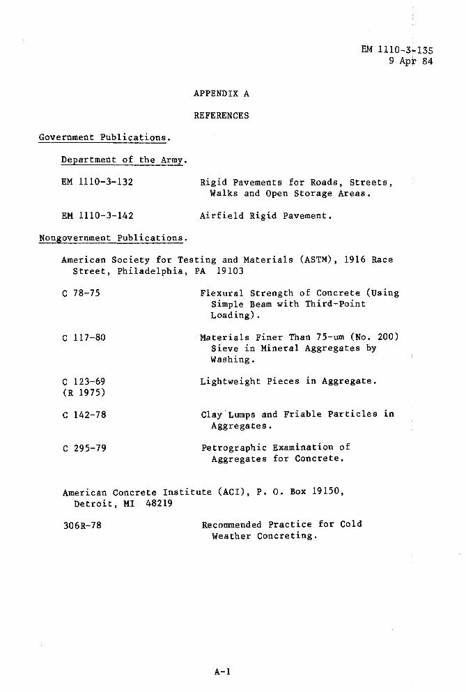
Rigid Pavements for Roads, Streets, Walks and Open Storage Areas.
Airfield Rigid Pavement.
American Society for Testing and Materials (ASTM), 1916 Race Street, Philadelphia, PA 19103
c 78-75
c 117-80
c 123-69 (R 1975)
c 142-78
c 295-79
Flexural Strength of Concrete (Using Simple Beam with Third-Point Loading).
Materials Finer Than 75-um (No. 200) Sieve in Mineral Aggregates by Washing.
Lightweight Pieces in Aggregate.
Clay Lumps and Friable Particles in Aggregates.
Petrographic Examination of Aggregates for Concrete.
American Concrete Institute (ACI), P. o. Box 19150, Detroit, MI 48219
306R-78 Recommended Practice for Cold Weather Concreting.
A-1