Embed Size (px)
Citation preview
8/3/2019 Papr Concrete Specifying Industrial Concrete Floors and Pavements
http://slidepdf.com/reader/full/papr-concrete-specifying-industrial-concrete-floors-and-pavements 1/11
__________________________________ 1
Director, MSC ConsultingGroup Ltd 2
Contracts Manager, Conslab Ltd
Specifying Industrial Concrete Floors & Pavements
Robert McGuigan1 B.E, F.I.P.E.N.Z, M.I.C.E, CPEng,, Timothy Walker
2 B.E
INTRODUCTION
The concrete floor is one of the most crucial elements of an industrial building, providing the operatingsurface on which pallets are stacked, forklifts are operated and racks are installed. There are a myriadof ways to design and build a concrete floor, a multitude of finishes to choose from, a variety ofreinforcing types to think about, countless curing methods to consider and endless ways to detail andlocate joints. Variety is the spice of life, but unfortunately it creates a conundrum for the industry – fornot all floors are created equal. To aid in the design and construction of quality floors MSC ConsultingGroup, JAWA Structures and Conslab have produced a suggested specification for use by industryprofessionals. This paper discusses the principal considerations when specifying an industrial concretefloor and can also be considered a commentary on the appended specification.
1.0 FLOOR TYPE AND DESIGN
Floor TypeThere are a variety of methodologies fordesigning, detailing and reinforcing anindustrial concrete floor. In New Zealandindustrial floors are predominantly meshreinforced, steel fibre reinforced, or post-tensioned. Other less popular options includefloors incorporating shrinkage compensatingconcrete, and unreinforced or semi-reinforcedfloors. Each type of floor offers differentcharacteristics in terms of performance,construction costs and likely futuremaintenance requirements.
The type of floor selected for a project willdepend largely on the design loading,subgrade conditions, the clients budget andexpectations for flatness, joint layout, surfaceappearance, serviceability and futuremaintenance requirements. As such it isdifficult to provide a one size fits allrecommendation on which type of floor tospecify.
Most performance and maintenance issues inindustrial floors occur at saw cut and formed joints. These are the areas that are most likelyto become damaged and are also the areasmost likely to interfere with the smoothoperation of material handling equipment. Itcan therefore be extremely beneficial to look tominimize or completely eliminate the presenceof these joints in a floor. This is achievableusing both “joint free” steel fibre reinforced,post-tensioned floors.
Floor DesignThe most predominant method for the ofdesign concrete floors in New Zealand is
presented in the CCANZ TM38 guide “ConcreteGround Floors & Pavements for Commercial and
Industrial Use, Part Two: Specific Design”. Thisapproach is based on the work of Westergaard. Itis important to note that this approach assumes anunreinforced slab for structural purposes – steelmesh, bar or steel fibre reinforcement is notconsidered to act to resist loads – it is merelyincorporated to control crack widths.
An alternative is the use of yield line analysis forthe design of industrial concrete floors. Thisapproach was first developed by Meyerhof andlater Losberg. In New Zealand the yield lineanalysis approach to floor design is typically only
employed by steel fibre suppliers, however itshould be noted that it is the predominantapproach to designing floors in the UnitedKingdom, where it is applied to floors reinforcedwith both steel fibre and mesh reinforcement.
Industrial concrete floors are generally subjected tothe following load types:
Point loads from the legs of storage racks.
Wheel loads from fork lift or reach trucksmoving in either random or defined directionsin the aisles or open areas of the floor.
Wheel loads from trucks delivering productinto the warehouse.Product stored direct on the floor e.g. heavycartons, pallets, bales or paper rolls.
A more detailed discussion of concrete floor designis outside of the scope of this paper, however it isworth noting that with the advent of specialistconcrete flooring firms in New Zealand it is nowpossible for industry professionals to “outsource”the design of floors using design/build contracts.
8/3/2019 Papr Concrete Specifying Industrial Concrete Floors and Pavements
http://slidepdf.com/reader/full/papr-concrete-specifying-industrial-concrete-floors-and-pavements 2/11
2.0 SUBGRADE AND SUBBASEFORMATIONThe structural integrity of the layers beneath aground supported slab is of vital importance tothe long term bearing capacity andserviceability of the slab. This section
discusses:The rationale for assessing the loadbearing capacity of the subgrades
Subgrade investigation and testing
Subgrade construction
Assessing the load by capacity of thesubgradeThe design of industrial concrete floorsgenerally assume that the subgrade is anelastic medium whose elasticity can becharacterised by the force that, distributed overunit area, will give a deflection equal to unity.
Westergaard termed this soil characteristic the‘modulus of subgrade reaction’, k, i.e. the loadper unit area causing unit deflection, with theunits N/mm
3. The modulus of subgrade
reaction is sometimes referred to as aresilience modulus and, in simple terms, thesubgrade may be considered to act as if it wererows of closely spaced but independent elasticsprings. Thus, the modulus of subgradereaction is equivalent to a spring constant andis a measure of the stiffness of the subgrade.
A detailed discussion of k values is given in the
comprehensive 1995 NCHRP Report 372,Support under Portland cement concretepavements. The report makes the importantrecommendations that the elastic k valuemeasured on the subgrade is the appropriateinput for design.
NCHRP Report 372 confirms that the k valuehas only a minor effect on slab thicknessdesign for flexural stresses and does not,therefore, need to be estimated with greataccuracy. The results in Table 1 below aretaken from Report 372 and show that errors up
to a value of 50% have a relatively small effecton slab thickness design. It should be notedhowever that deflections are more sensitive tok values.
Table 1: Error in slab thickness design resulting from error in estimation of modulus of subgrade reaction, k. (From
NCHRP Report 372).
Error in k value, %Typical maximum error in
slab thickness, %
10
25
50
1
2.5
5
Subgrade investigation and testingMaterials at deeper levels below the groundsurface have their most significant effect on thelong-term settlement of the slab. For a loadedfloor, the bulb of pressure under loads will extend
its influence to a depth well into, and possiblybeyond, the subgrade or filled areas. There istherefore the potential for long-term settlements tobe much larger than the elastic deflectionscalculated as part of the slab design. This effectcould result in differential settlement betweenheavily and lightly loaded areas, with a consequenteffect on floor surface regularity.
Materials closer to the ground surface have moreeffect on the measured subgrade properties thanthose at larger depths. The near-to-surfaceproperty of the subgrade that is used in the
thickness design of a slab is the modulus ofsubgrade reaction, k.
Elastic k values do not reflect long-termsettlements due to soil consolidation under loading.However, low values of k are indicative of plasticbehaviour of the near-to-surface soils. Checksshould be made on the likely deformation of thesubgrade, particularly for soils with low k values.
To estimate long-term or differential settlements ageotechnical engineer should be consulted withregard to appropriate site investigation, soil testing
and interpretation.
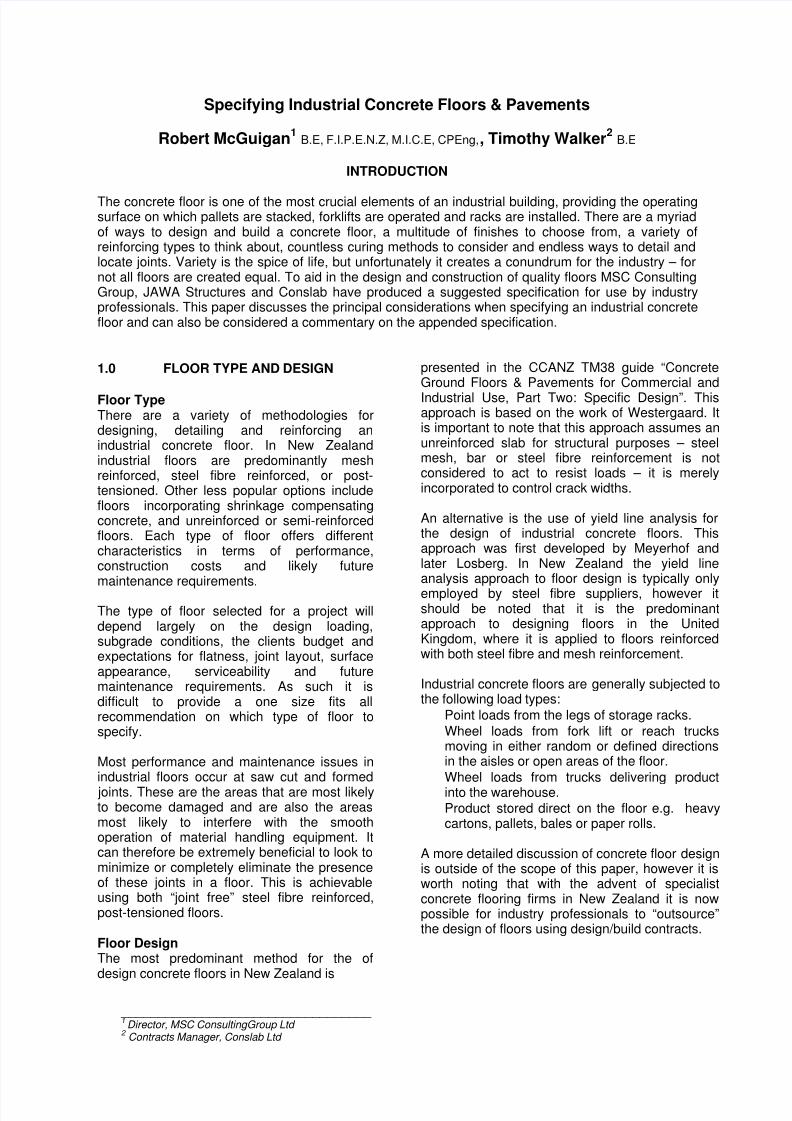
California Bearing Ratio (CBR) tests aresometimes used to assess soils performancealthough the results are less representative oflong-term potential soils performance. Figure 1below shows the approximate relationship betweenCBR and k values. The CBR is the ratio ofresistance to penetration developed by a subgradesoil to that developed by a specimen of standardcrushed rock. The test was developed as alaboratory test, but where used, determination ofCBR should be carried out in situ.
Figure 1: Relationship between modulus of subgrade reaction and in situ CBR.
8/3/2019 Papr Concrete Specifying Industrial Concrete Floors and Pavements
http://slidepdf.com/reader/full/papr-concrete-specifying-industrial-concrete-floors-and-pavements 3/11
In some cases reliance will be placed on anassessment of k based on soil types. Table 2gives below gives an indication of typicalvalues of k related to soil type.
Table 2: Typical values of modulus of subgrade reaction k related to soil type.
k value (N/mm3)
Soil Type
Lower value Upper value
Fine or slightlycompacted sand
0.015 0.03
Well compacted sand 0.05 0.10
Very well compactedsand
0.10 0.15
Loam or clay (moist) 0.03 0.06
Loam or clay (dry) 0.08 0.10
Clay with sand 0.08 0.10
Crushed stone withsand
0.10 0.15
Coarse crushed stone 0.20 0.25
Well compactedcrushed stone
0.20 0.30
Subgrade PreparationThe design of the slab thickness is notparticularly sensitive to the thickness of thesubbase material; accordingly the as built levelat the top of the subgrade can have a degreeof tolerance. We consider that an appropriateand realistically achievable tolerance is +25mm at subgrade level. The thickness ofbase course chosen is fairly nominal and wenormally specify 150mm to 200mm dependingon the condition of the subgrade. This is a judgment call on the part of the Engineerdepending on the expected condition of the
subgrade, availability of suitable economicalmetals and possibly the expected time of theyear construction may take place.
We consider it prudent that for the record andto ensure the correct levels are constructed acompetent surveyor be engaged afterconstruction of the subgrade to provide an asbuilt levels plan to the Engineer.
On completion of the subgrade formationtesting of the subgrade should take place toverify the value of modulus of subgrade
reaction, k, used in the design. This testingshould be carried out under the observation ofeither the project Geotechnical Engineer or the
project Design Engineer and will generallycomprise either, plate loading tests, ScalaPenetrometer tests or Benkelman Beam testingdepending on the type of subgrade.
Testing of subgrades in Cut
Particularly if the subgrade is clayey, as for most ofNew Zealand, then we recommend that the testingbe carried out at a level approximately a nominal50mm above the final subgrade level. This is up tothe Engineer and Contractor on site but suggestedbecause in clayey soils the process of testingparticularly with a Benkelman Beam truck, candamage the surface.
Following approval of the test results final trimmingto subgrade level can be completed or if the resultsare not acceptable decisions can be made to eitherundercut or possibly stabilize the surface to
achieve the required strength.
Testing of subgrade in FillWhere filling the site is required then thecompacted fill material should be placed up to thedesign subgrade level. At that stage the subgradetesting should be carried out to determine the kvalue of the construction subgrade as confirmationfor the Engineers’ decision.
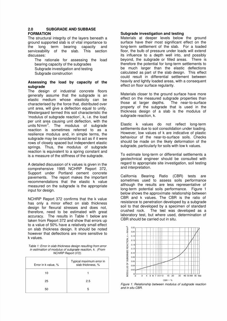
Subbase FormationSubbases are usually constructed from stable, wellgraded granular material complying with, and laid
in accordance with the Highways AgencySpecification for highways works, Series 800,Road pavements – unbound materials. Subbasematerial Type 1 is preferred. Cement-stabilizedsubbases in accordance with the Highways AgencySpecification for highways works, Series 1000,Road pavements – concrete and cement boundmaterials are also occasionally used.
Figure 2 : Subbase preparation
Where other types of subbase are used, such ascement bound materials, then if advantage is to be
taken in respect of load-carrying capacity of thefloor, an alternative form of analysis maybe
8/3/2019 Papr Concrete Specifying Industrial Concrete Floors and Pavements
http://slidepdf.com/reader/full/papr-concrete-specifying-industrial-concrete-floors-and-pavements 4/11
required that is beyond the scope of theguidance in this paper.
If granular material is used, the subbaseshould have a minimum thickness of 150 mm.
Where a soils survey has shown the subgradeto be adequate to provide support directly tothe slab (e.g. a granular material with k morethan 150) it may be appropriate to lay the slabdirectly on the subgrade. However, the effectsof plant movement and weather conditionsmust be taken into account when consideringthe omission of a subbase.
Checks should be made to ensure thatsubbase materials do not produce deleteriousproducts likely to attack the concretechemically nor expand or contract excessively
with moisture movement.
Of particular importance for the constructionand performance of the slab is the fact that thesurface of the subbase should be well closedand free from movement under compactionplant and from ridges, cracks, loose material,potholes, ruts or other defects.
Any trimming of the surface should leave thesubbase homogenous and well compacted.Trimming layers cannot make up fordeficiencies in the subbase construction. A
sand binding layer should not be used. Sandmay be used for closing the surface of coarsergrained materials but any residual layer of sandat the surface should not be more than 5mmthick.
Research has shown that a compactedgranular subbase only marginally enhances theability of the subgrade to support the concreteslab and its loads. Any enhancement of themodulus of subgrade reaction produced by acompacted granular subbase is so small that,compared with the variations in properties that
will occur in a natural soil, it should beneglected in the design process. The modulusof subgrade reaction should always, thereforebe measured on the subgrade. However, thisdoes not remove the need for good subbaseconstruction practice.
Subbase Surface ToleranceIt is essential to minimize the risk that the slabtop level and subbase top surface are both outof tolerance at the same point and in theadverse direction as this may reduce thethickness of the concrete slab so much that its
load-carrying capacity is reduced to anunacceptable extent. Therefore, the finishedsurface of the subbase should be within +0 to -
25 mm of the datum for the bottom of the slab inaccordance with BS 8204-2. Construction of thesubbase to tighter tolerances should beencouraged as this reduces wastage and providesa flatter subbase. Positive tolerance above zerodatum should not be permitted as these will directly
effect the thickness of the slab. Subbase finishedlevels should be surveyed at an appropriatenumber of points. It will be beneficial if thesesurvey points coincide with a planned grid ofsurvey points for the top level of the slab, to verifythe actual slab thickness.
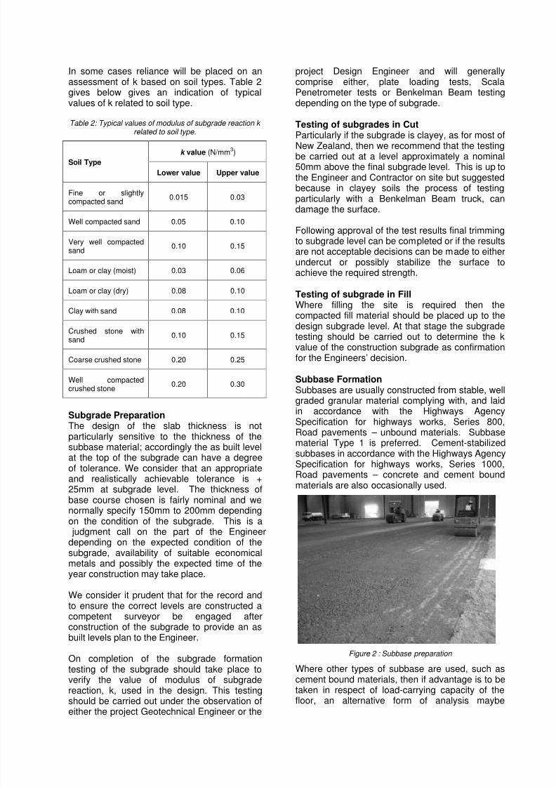
Our recommendation is that the top surface of thesubbase should be placed to achieve a toleranceof +0 mm or -10 mm, this should be measured onthe completed blinded surface. We are nowspecifying that a Registered Surveyor be engagedat this stage to produce an as built plan and
certification that these tolerances have beenachieved. This tolerance is quite achievablehowever, laser guided equipment will generally berequired.
Figure 3 : Subbase finished levels are surveyed
4.0 UNDER FLOOR MEMBRANEThe main purposes of an under floor membrane isto provide:
Resistance to rising dampReduction in friction between the slabmembrane and the subbase surface.
Membranes are normally plastic sheeting tocomply with the N.Z Standard Building Code. NZS3604 clause 7.5.4.2 seems to be the mostcomprehensive guideline.
It is important to lay the membrane without creasesand overlapped at the edges by at least 300mm,and to ensure that it is not damaged during theconstruction process. The plastic sheet will inhibit
the loss of water and fines from the concrete to thesubbase and can, where required act as a watervapour resistant membrane.
8/3/2019 Papr Concrete Specifying Industrial Concrete Floors and Pavements
http://slidepdf.com/reader/full/papr-concrete-specifying-industrial-concrete-floors-and-pavements 5/11
It is worth noting that specialist gasmembranes and venting systems arebecoming more common as more and moreconstruction is carried out on contaminatedland.
5.0 FLOOR SURFACE REGULARITY
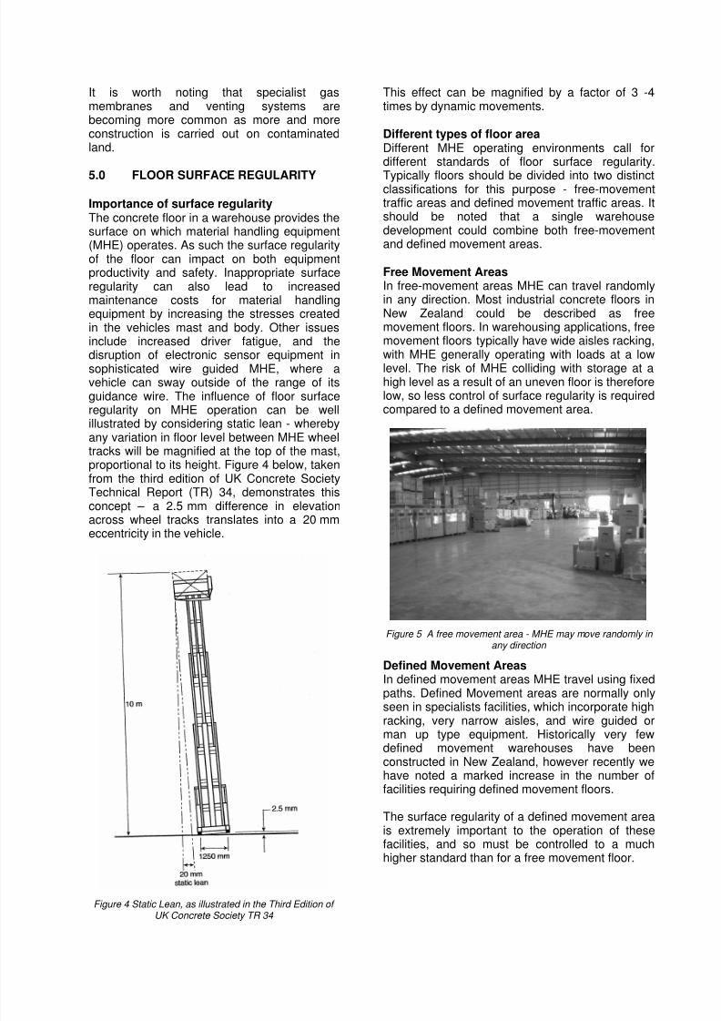
Importance of surface regularityThe concrete floor in a warehouse provides thesurface on which material handling equipment(MHE) operates. As such the surface regularityof the floor can impact on both equipmentproductivity and safety. Inappropriate surfaceregularity can also lead to increasedmaintenance costs for material handlingequipment by increasing the stresses createdin the vehicles mast and body. Other issuesinclude increased driver fatigue, and the
disruption of electronic sensor equipment insophisticated wire guided MHE, where avehicle can sway outside of the range of itsguidance wire. The influence of floor surfaceregularity on MHE operation can be wellillustrated by considering static lean - wherebyany variation in floor level between MHE wheeltracks will be magnified at the top of the mast,proportional to its height. Figure 4 below, takenfrom the third edition of UK Concrete SocietyTechnical Report (TR) 34, demonstrates thisconcept – a 2.5 mm difference in elevationacross wheel tracks translates into a 20 mm
eccentricity in the vehicle.
Figure 4 Static Lean, as illustrated in the Third Edition of UK Concrete Society TR 34
This effect can be magnified by a factor of 3 -4times by dynamic movements.
Different types of floor areaDifferent MHE operating environments call fordifferent standards of floor surface regularity.
Typically floors should be divided into two distinctclassifications for this purpose - free-movementtraffic areas and defined movement traffic areas. Itshould be noted that a single warehousedevelopment could combine both free-movementand defined movement areas.
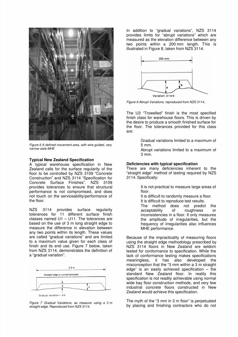
Free Movement AreasIn free-movement areas MHE can travel randomlyin any direction. Most industrial concrete floors inNew Zealand could be described as freemovement floors. In warehousing applications, freemovement floors typically have wide aisles racking,
with MHE generally operating with loads at a lowlevel. The risk of MHE colliding with storage at ahigh level as a result of an uneven floor is thereforelow, so less control of surface regularity is requiredcompared to a defined movement area.
Figure 5 A free movement area - MHE may move randomly in any direction
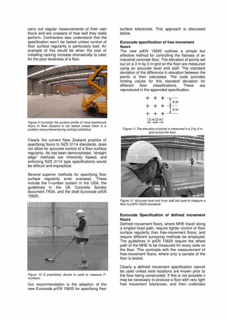
Defined Movement AreasIn defined movement areas MHE travel using fixedpaths. Defined Movement areas are normally onlyseen in specialists facilities, which incorporate highracking, very narrow aisles, and wire guided orman up type equipment. Historically very fewdefined movement warehouses have beenconstructed in New Zealand, however recently wehave noted a marked increase in the number offacilities requiring defined movement floors.
The surface regularity of a defined movement areais extremely important to the operation of thesefacilities, and so must be controlled to a muchhigher standard than for a free movement floor.
8/3/2019 Papr Concrete Specifying Industrial Concrete Floors and Pavements
http://slidepdf.com/reader/full/papr-concrete-specifying-industrial-concrete-floors-and-pavements 6/11
Figure 6 A defined movement area, with wire guided, very narrow aisle MHE
Typical New Zealand SpecificationA typical warehouse specification in NewZealand calls for the surface regularity of thefloor to be controlled by NZS 3109 “Concrete
Construction” and NZS 3114 “Specification forConcrete Surface Finishes”. NZS 3109provides tolerances to ensure that structuralperformance is not compromised, and doesnot touch on the serviceability/performance ofthe floor.
NZS 3114 provides surface regularitytolerances for 11 different surface finishclasses named U1 – U11. The tolerances arebased on the use of 3 m long straight edge tomeasure the difference in elevation betweenany two points within its length. These values
are called “gradual variations” and are limitedto a maximum value given for each class offinish and its end use. Figure 7 below, takenfrom NZS 3114, demonstrates the definition ofa “gradual variation”.
Figure 7 Gradual Variations, as measure using a 3 m straight edge. Reproduced from NZS 3114.
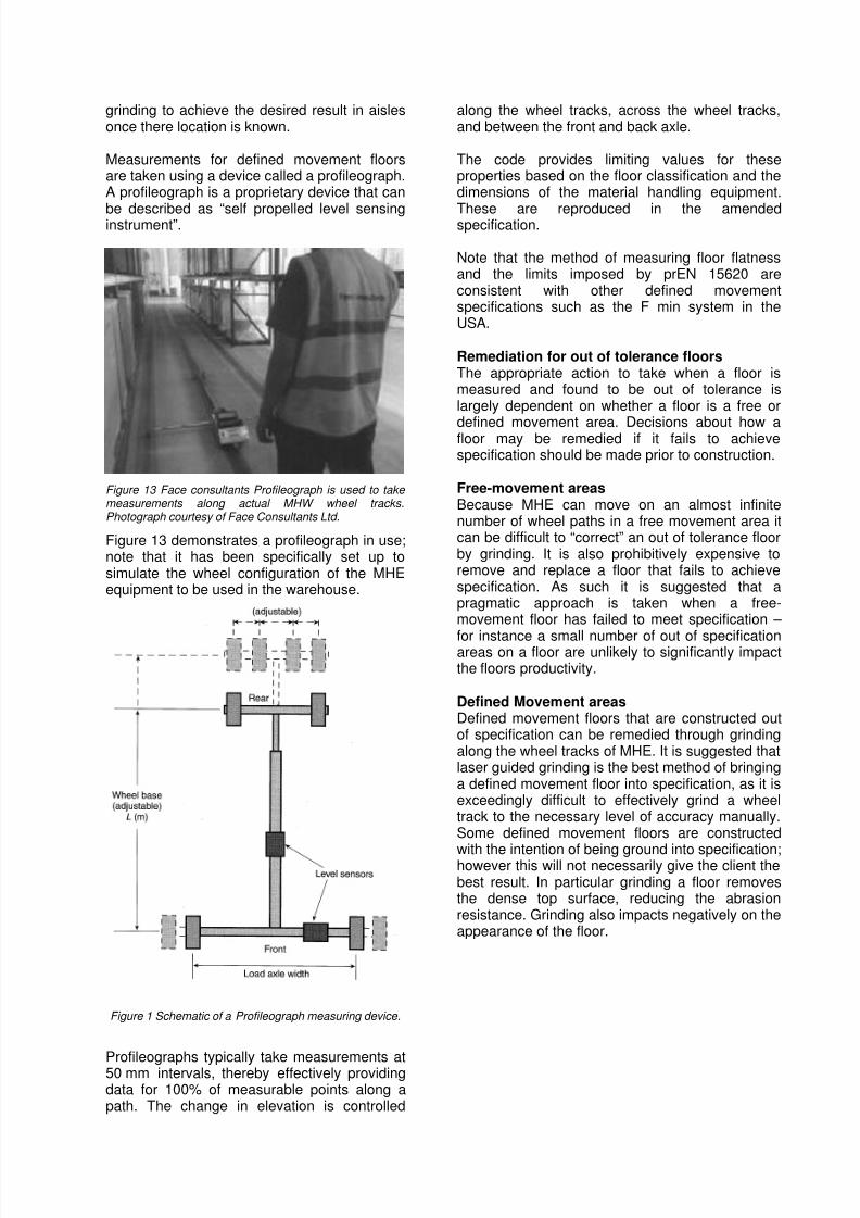
In addition to “gradual variations”, NZS 3114provides limits for “abrupt variations” which aremeasured as the elevation difference between anytwo points within a 200 mm length. This isillustrated in Figure 8, taken from NZS 3114.
Figure 8 Abrupt Variations, reproduced from NZS 3114..
The U3 “Trowelled” finish is the most specified
finish class for warehouse floors. This is driven bythe desire to produce a smooth finished surface forthe floor. The tolerances provided for this classare:
Gradual variations limited to a maximum of5 mm.
Abrupt variations limited to a maximum of3 mm.
Deficiencies with typical specificationThere are many deficiencies inherent to the“straight edge” method of testing required by NZS
3114. Specifically:
It is not practical to measure large areas offloor.
It is difficult to randomly measure a floor.
It is difficult to reproduce test results.
The method does not predict theacceptability of roughness orinconsistencies in a floor. It only measuresthe amplitude of irregularities, but thefrequency of irregularities also influencesMHE performance.
Because of the impracticality of measuring floorsusing the straight edge methodology prescribed byNZS 3114 floors in New Zealand are seldomtested for conformance to specification. While thelack of conformance testing makes specificationsmeaningless, it has also developed themisconception that the “3 mm within a 3 m straightedge” is an easily achieved specification – thestandard New Zealand floor. In reality thisspecification is not readily achievable using normalwide bay floor construction methods, and very fewindustrial concrete floors constructed in NewZealand would achieve this specification.
The myth of the “3 mm in 3 m floor” is perpetuatedby placing and finishing contractors who do not
8/3/2019 Papr Concrete Specifying Industrial Concrete Floors and Pavements
http://slidepdf.com/reader/full/papr-concrete-specifying-industrial-concrete-floors-and-pavements 7/11
carry out regular measurements of their ownfloors and are unaware of how well they reallyperform. Contractors also understand that thespecification won’t be tested unless control offloor surface regularity is particularly bad. Anexample of this would be when the cost of
installing racking increase dramatically to caterfor the poor levelness of a floor.
Figure 9 Currently the surface profile of most warehouse floors in New Zealand is not tested unless there is a problem encountered during racking installation
Clearly the current New Zealand practice ofspecifying floors to NZS 3114 standards, doesnot allow for accurate control of a floor surfaceregularity. As has been demonstrated, “straightedge” methods are inherently flawed, andenforcing NZS 3114 type specifications wouldbe difficult and impractical.
Several superior methods for specifying floorsurface regularity exist overseas. Theseinclude the f-number system in the USA, theguidelines in the UK Concrete Societydocument TR34, and the draft Eurocode prEN15620.
Figure 10 A proprietary device is used to measure F- numbers.
Our recommendation is the adoption of thenew Eurocode prEN 15620 for specifying floor
surface tolerances. This approach is discussedbelow.
Eurocode specification of free movementfloorsThe new prEN 15620 outlines a simple but
effective method for controlling the flatness of anindustrial concrete floor. The elevation of points setout on a 3 m by 3 m grid on the floor are measuredusing an accurate level and staff. The standarddeviation of the difference in elevation between thepoints is then calculated. The code provideslimiting values for this standard deviation fordifferent floor classifications. These arereproduced in the appended specification.
Figure 11 The elevation of points is measured in a 3 by 3 m grid across the floor.
Figure 12 Accurate level and Invar staff are used to measure a floor to prEN 15620 standards
Eurocode Specification of defined movementfloors
Defined movement floors, where MHE travel alonga singled fixed path, require tighter control of floorsurface regularity than free-movement floors, andrequire different surveying methods be employed.The guidelines in prEN 15620 require the wheelpath of the MHE to be measured for every aisle onthe floor. This contrasts with the measurement offree-movement floors, where only a sample of thefloor is tested.
Clearly a defined movement specification cannotbe used unless aisle locations are known prior tothe floor being constructed. If this is not possible it
may be necessary to produce a floor with very tightfree movement tolerances, and then undertake
8/3/2019 Papr Concrete Specifying Industrial Concrete Floors and Pavements
http://slidepdf.com/reader/full/papr-concrete-specifying-industrial-concrete-floors-and-pavements 8/11
grinding to achieve the desired result in aislesonce there location is known.
Measurements for defined movement floorsare taken using a device called a profileograph.A profileograph is a proprietary device that can
be described as “self propelled level sensinginstrument”.
Figure 13 Face consultants Profileograph is used to take measurements along actual MHW wheel tracks.Photograph courtesy of Face Consultants Ltd.
Figure 13 demonstrates a profileograph in use;note that it has been specifically set up tosimulate the wheel configuration of the MHEequipment to be used in the warehouse.
Figure 1 Schematic of a Profileograph measuring device.
Profileographs typically take measurements at50 mm intervals, thereby effectively providingdata for 100% of measurable points along apath. The change in elevation is controlled
along the wheel tracks, across the wheel tracks,and between the front and back axle.
The code provides limiting values for theseproperties based on the floor classification and thedimensions of the material handling equipment.
These are reproduced in the amendedspecification.
Note that the method of measuring floor flatnessand the limits imposed by prEN 15620 areconsistent with other defined movementspecifications such as the F min system in theUSA.
Remediation for out of tolerance floorsThe appropriate action to take when a floor ismeasured and found to be out of tolerance islargely dependent on whether a floor is a free or
defined movement area. Decisions about how afloor may be remedied if it fails to achievespecification should be made prior to construction.
Free-movement areasBecause MHE can move on an almost infinitenumber of wheel paths in a free movement area itcan be difficult to “correct” an out of tolerance floorby grinding. It is also prohibitively expensive toremove and replace a floor that fails to achievespecification. As such it is suggested that apragmatic approach is taken when a free-movement floor has failed to meet specification –
for instance a small number of out of specificationareas on a floor are unlikely to significantly impactthe floors productivity.
Defined Movement areasDefined movement floors that are constructed outof specification can be remedied through grindingalong the wheel tracks of MHE. It is suggested thatlaser guided grinding is the best method of bringinga defined movement floor into specification, as it isexceedingly difficult to effectively grind a wheeltrack to the necessary level of accuracy manually.Some defined movement floors are constructed
with the intention of being ground into specification;however this will not necessarily give the client thebest result. In particular grinding a floor removesthe dense top surface, reducing the abrasionresistance. Grinding also impacts negatively on theappearance of the floor.
8/3/2019 Papr Concrete Specifying Industrial Concrete Floors and Pavements
http://slidepdf.com/reader/full/papr-concrete-specifying-industrial-concrete-floors-and-pavements 9/11
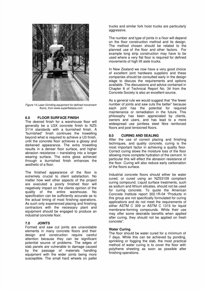
Figure 14 Laser Grinding equipment for defined movement floors, from www.superflatasia.com
6.0 FLOOR SURFACE FINISHThe desired finish for a warehouse floor willgenerally be a U3X concrete finish to NZS3114 standards with a burnished finish. A“burnished” finish continues the trowellingbeyond what is required to achieve a U3 finish,until the concrete floor achieves a glossy anddarkened appearance. The extra trowellingresults in a denser floor surface, and higher
abrasion resistance – translating into a longerwearing surface. The extra gloss achievedthrough a burnished finish enhances theaesthetic of a floor.
The finished appearance of the floor isextremely crucial to client satisfaction. Nomatter how well other aspects of the projectare executed a poorly finished floor willnegatively impact on the clients opinion of thequality of the entire warehouse. Nospecification can be sufficiently accurate as tothe actual timing of most finishing operations.
As such only experienced placing and finishingcontractors with the necessary plant andequipment should be engaged to produce anindustrial concrete floor.
7.0 JOINTSFormed and saw cut joints are unavoidableelements in many concrete floors and theirdesign and construction require carefulattention because they can be significantpotential source of problems. The edges ofslab panels are vulnerable to damage causedby the passage of materials handling
equipment with the wider joints being moresusceptible. The small hard wheels on pallet
trucks and similar fork hoist trucks are particularlyaggressive.
The number and type of joints in a floor will dependon the floor construction method and its design.The method chosen should be related to the
planned use of the floor and other factors. Forexample long strip construction may have to beused where a very flat floor is required for definedmovements of high lift aisle trucks.
In New Zealand we now have a very good choiceof excellent joint hardware suppliers and thesecompanies should be consulted early in the designstage to discuss the requirements and optionsavailable. The discussions and advice contained inChapter 8 of Technical Report No. 34 from theConcrete Society is also an excellent source.
As a general rule we would suggest that “the fewernumber of joints and saw cuts the better” becauseeach joint has the potential for requiredmaintenance or remediation in the future. Thisphilosophy has been appreciated by clients,owners and users, and has lead to a morewidespread use jointless steel fibre reinforcedfloors and post tensioned floors.
8.0 CURING AND SEALINGAfter the use of correct placing and finishingtechniques, and quality concrete, curing is themost important factor in achieving a quality floor.
Correct curing slows the moisture loss of the floorallowing more complete hydration of the cement. Inparticular this will effect the abrasion resistance ofthe floor. Curing will also reduce early carbonationof the floors surface.
Industrial concrete floors should either be watercured, or cured using an NZS3109 compliantcuring compound. Liquid surface treatments, suchas sodium and lithium silicates, should not be usedfor curing concrete. To quote the AmericanConcrete Institute report 302.1R-04 “Products inthis group are not specifically formulated for curing
applications and do not meet the requirements ofeither ASTM C 309 or ASTM C 1315 for liquidmembrane-forming compounds. While their usemay offer some desirable benefits when appliedafter curing, they should not be applied on freshconcrete”.
Water CuringThe floor should be water cured for a minimum of7 days. While this can be achieved by ponding,sprinkling or fogging the slab, the most practicalmethod of water curing is to cover the floor withpolythene sheeting as soon as possible after
finishing operations.
8/3/2019 Papr Concrete Specifying Industrial Concrete Floors and Pavements
http://slidepdf.com/reader/full/papr-concrete-specifying-industrial-concrete-floors-and-pavements 10/11
Be aware that polythene curing will causestaining on the surface of the floor. This willbecome significantly less noticeable with time.Polythene can become extremely slipperywhen wet, and so all trades should be aware ofthe health and safety implications of working
on a floor that is covered with polythene.
Liquid Membrane Forming CuringCompoundsLiquid membrane forming curing compoundsarea a widely accepted method for curingconcrete floors, particularly in the USA and UKwhere they are the most common method ofcuring industrial floor. A curing compoundoffers some key advantages over water curing,particularly because they offer a longuninterrupted curing time when compared tothe 7 day curing typically achieved with water
curing.
They will also not stain the floor in the sameway polythene sheeting will, and depending onthe compound chosen can actually enhancethe early age appearance of the floor byproviding a dark and glossy finish.Disadvantages of the use of a liquid membraneforming curing compound include issues withachieving an adequate and even coverage,and the potential to interfere with appliedcoverings and liquid surface treatments suchas sodium silicates.
The compound chosen should meet or exceedthe moisture retention requirements of ASTMC309, which will ensure that it complies withNZS3109 requirements for curing. It should beapplied as soon as finishing operations arecompleted, while the surface is still damp butfree of standing water.
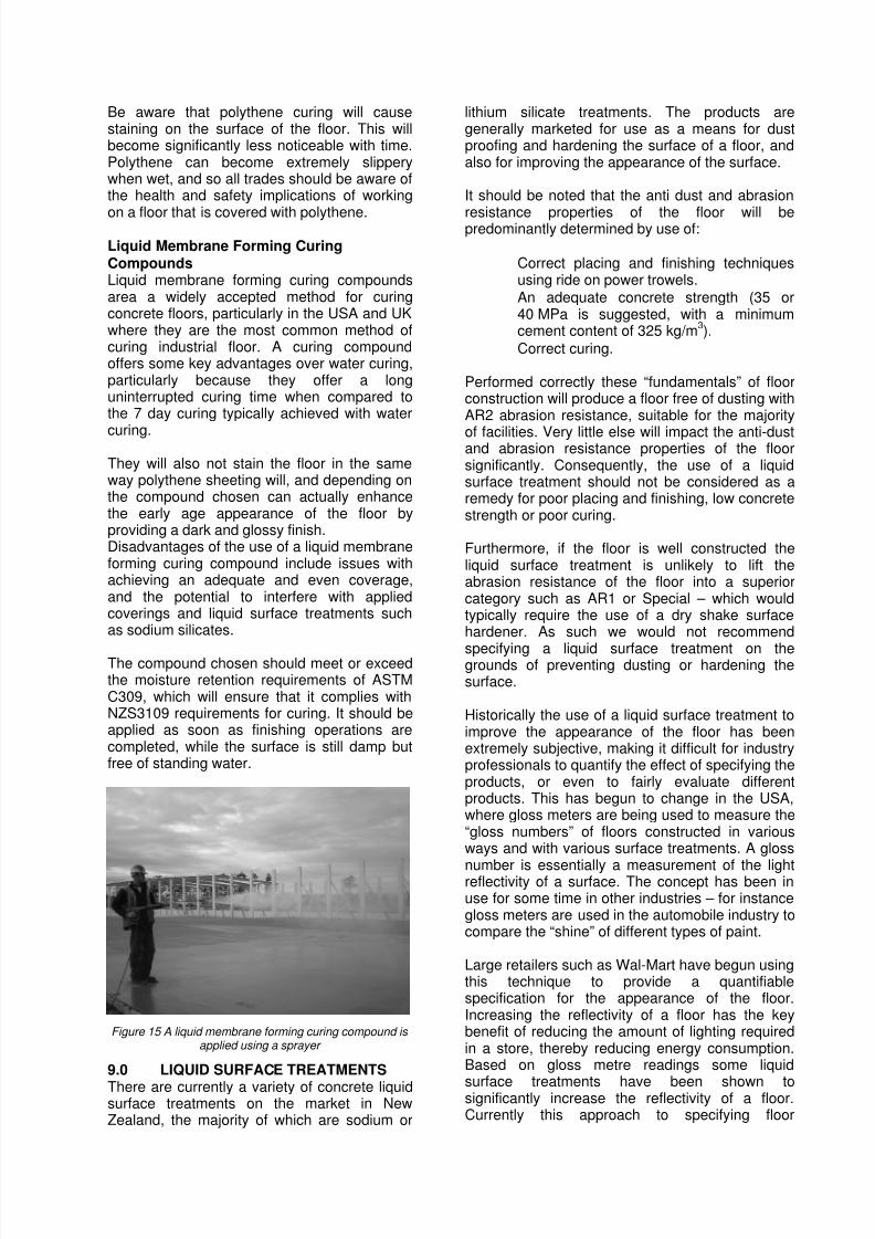
Figure 15 A liquid membrane forming curing compound is applied using a sprayer
9.0 LIQUID SURFACE TREATMENTS
There are currently a variety of concrete liquidsurface treatments on the market in NewZealand, the majority of which are sodium or
lithium silicate treatments. The products aregenerally marketed for use as a means for dustproofing and hardening the surface of a floor, andalso for improving the appearance of the surface.
It should be noted that the anti dust and abrasion
resistance properties of the floor will bepredominantly determined by use of:
Correct placing and finishing techniquesusing ride on power trowels.An adequate concrete strength (35 or40 MPa is suggested, with a minimumcement content of 325 kg/m
3).
Correct curing.
Performed correctly these “fundamentals” of floorconstruction will produce a floor free of dusting withAR2 abrasion resistance, suitable for the majority
of facilities. Very little else will impact the anti-dustand abrasion resistance properties of the floorsignificantly. Consequently, the use of a liquidsurface treatment should not be considered as aremedy for poor placing and finishing, low concretestrength or poor curing.
Furthermore, if the floor is well constructed theliquid surface treatment is unlikely to lift theabrasion resistance of the floor into a superiorcategory such as AR1 or Special – which wouldtypically require the use of a dry shake surfacehardener. As such we would not recommend
specifying a liquid surface treatment on thegrounds of preventing dusting or hardening thesurface.
Historically the use of a liquid surface treatment toimprove the appearance of the floor has beenextremely subjective, making it difficult for industryprofessionals to quantify the effect of specifying theproducts, or even to fairly evaluate differentproducts. This has begun to change in the USA,where gloss meters are being used to measure the“gloss numbers” of floors constructed in variousways and with various surface treatments. A gloss
number is essentially a measurement of the lightreflectivity of a surface. The concept has been inuse for some time in other industries – for instancegloss meters are used in the automobile industry tocompare the “shine” of different types of paint.
Large retailers such as Wal-Mart have begun usingthis technique to provide a quantifiablespecification for the appearance of the floor.Increasing the reflectivity of a floor has the keybenefit of reducing the amount of lighting requiredin a store, thereby reducing energy consumption.Based on gloss metre readings some liquid
surface treatments have been shown tosignificantly increase the reflectivity of a floor.Currently this approach to specifying floor
8/3/2019 Papr Concrete Specifying Industrial Concrete Floors and Pavements
http://slidepdf.com/reader/full/papr-concrete-specifying-industrial-concrete-floors-and-pavements 11/11
properties has not been trialled locally,however it has some strong merits and weanticipate that this process could find its wayinto the New Zealand market in the near future.
10 PROTECTING THE FLOOR AFTER
POURING The new floor should be left undisturbed for aminimum of three days following pouring toallow the concrete to harden enough to avoiddamage to the surface or at joints. In coldweather the floor may need to be left longerthan three days. After this period pedestrianaccess to the floor could be permitted, howeverthe floor is still susceptible to impact damagefrom dropped objects and could be scratchedby poor material handling practices.
The floor should generally not be subjected to
any vehicle loads until after at least 7 days.The decision to allow the floor to be loadedshould take into account the evolution ofcompressive strength of the concrete based ononsite compressive strength testing.
Any spilled oil or other substances such ashydraulic fluid will permanently stain the floor.Ideally hoists and other vehicles should befitted with drip catchers to stop fluids beingdropped on the surface. A spill kit can beplaced on site to be used immediately if anyfluid is spilled on the floor.
The tyres of vehicles should also be covered toavoid black tyre marks being left on the floor(white non-marking tyres are available forsome vehicles as an alternative). Theappearance of the floor will improve over time ifit is regularly machine scrubbed. This processcan be accelerated by repeated early machinecleaning.
11 CONCLUSIONExperience over many years of designingindustrial buildings has convinced the authors
that the performance of the floor slab is secondonly in importance to the weather tightness andsecurity of the building. In fact a leak in theroof due to breakdown of the cladding orflexibility of the structure, or a breach ofsecurity due to flimsy cladding, are generallyeasily and cheaply fixed.
However, if the floor slab is not fit for purposeeither because it breaks down with materialshandling equipment use or it cracks and movesin the wrong places the remediation isextremely costly and often not particularly
effective, at least in the long term.
Recently we have been measuring completedfloors using the 3 m by 3 m grid survey methoddescribed in prEN 15620. We have been verypleased that our floors have matched thetolerances outlined in this standards. In otherwords the specialist concrete floor slab contractors
in New Zealand are able to produce the goods.
In collaboration with Conslab, Gary James of JawaStructures and MSC Consulting Group we haveprepared a specification which MSC is now usingon current projects. This specification requires thatthe contractor provide as built results based onprecise levelling on the 3 m grid. It also outlines(clause 1.10 Non Compliance) the possibleremedies that the Engineer might consider onbehalf of the owner in the event that the tolerancesspecified are not met.
A copy of this specification is appended to thispaper and we recommend that you consider itsuse, albeit modified to your own requirements ortolerances.