Embed Size (px)
Citation preview
Page 1 of 14 Military Vehicle Filters Issue 8, April 2016 Web: www.mpe.co.uk This information is for guidance only E-mail: [email protected]
MPE reserve the right to make changes without notice Tel / Fax: +44 (0) 151 632 9100 / 9112 © 2006 - 2016 MPE Limited
EMC FILTERS FOR MILITARY VEHICLES
STANDARD EMC FILTER SOLUTIONS
FOR MILITARY VEHICLES
TO ENABLE VEHICLE EQUIPMENT TO COMPLY WITH DEF STAN 59-411, MIL-STD-461, etc
All products in this brochure are RoHS compliant
MPE Limited
Hammond Road Knowsley Industrial Park
Liverpool L33 7UL, UK
Page 2 of 14 Military Vehicle Filters Issue 8, April 2016 Web: www.mpe.co.uk This information is for guidance only E-mail: [email protected]
MPE reserve the right to make changes without notice Tel / Fax: +44 (0) 151 632 9100 / 9112 © 2006 - 2016 MPE Limited
EMC FILTERS FOR MILITARY VEHICLES
STANDARD EMC FILTER SOLUTIONS
FOR MILITARY VEHICLES
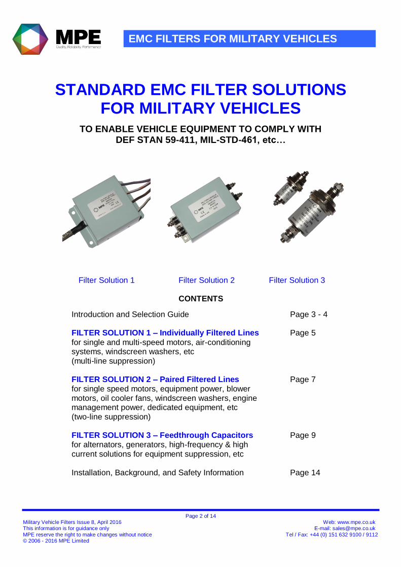
TO ENABLE VEHICLE EQUIPMENT TO COMPLY WITH DEF STAN 59-411, MIL-STD-461, etc…
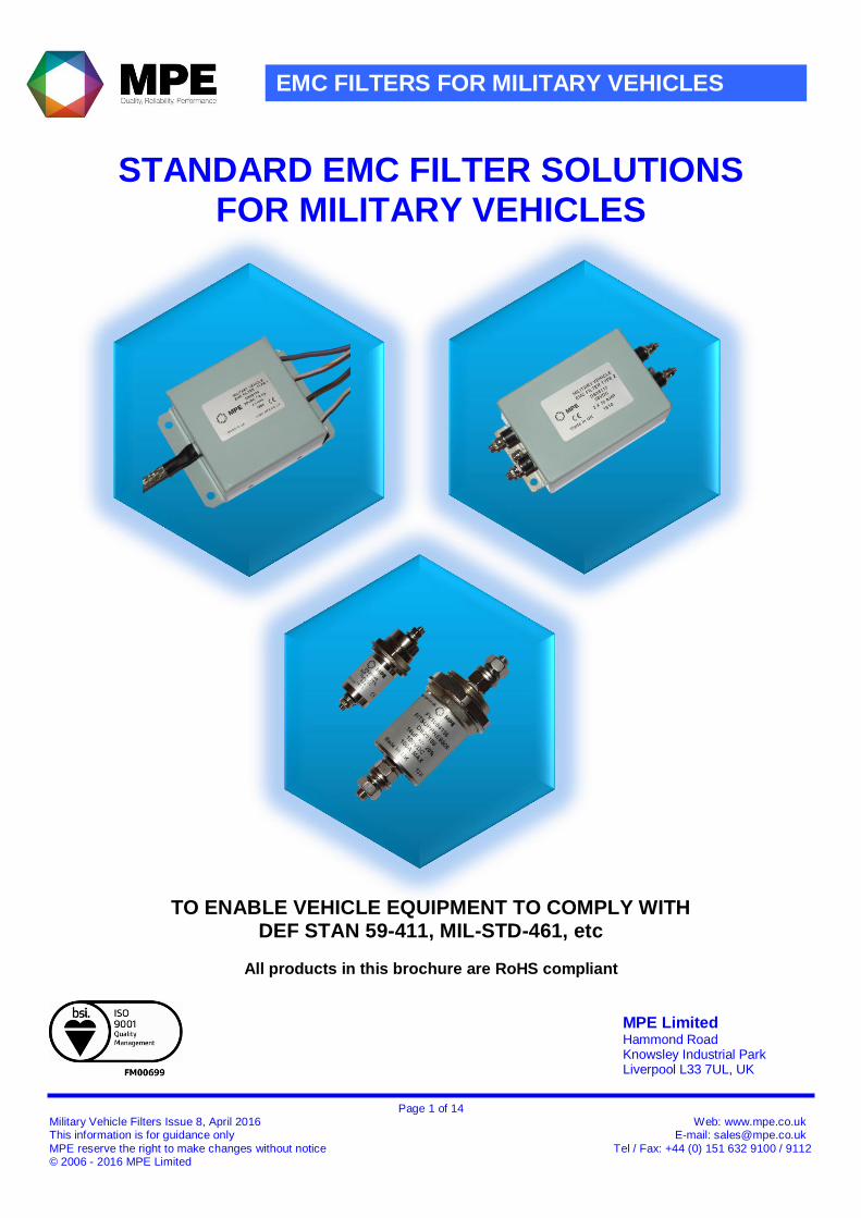
Filter Solution 1 Filter Solution 2 Filter Solution 3
CONTENTS
Introduction and Selection Guide Page 3 - 4
FILTER SOLUTION 1 – Individually Filtered Lines Page 5
for single and multi-speed motors, air-conditioning systems, windscreen washers, etc (multi-line suppression)
FILTER SOLUTION 2 – Paired Filtered Lines Page 7 for single speed motors, equipment power, blower motors, oil cooler fans, windscreen washers, engine management power, dedicated equipment, etc (two-line suppression)
FILTER SOLUTION 3 – Feedthrough Capacitors Page 9
for alternators, generators, high-frequency & high current solutions for equipment suppression, etc
Installation, Background, and Safety Information Page 14
Page 3 of 14 Military Vehicle Filters Issue 8, April 2016 Web: www.mpe.co.uk This information is for guidance only E-mail: [email protected]
MPE reserve the right to make changes without notice Tel / Fax: +44 (0) 151 632 9100 / 9112 © 2006 - 2016 MPE Limited
EMC FILTERS FOR MILITARY VEHICLES
Introduction This brochure covers a standard range of cost effective MOTS (military-off-the-shelf) filters suitable for EMC suppression of COTS (commercial-of-the-shelf) equipment on military vehicles - to help meet the requirements of military EMC specifications such as DEF STAN 59-411 and MIL-STD-461. MPE have been designing and manufacturing custom EMC filters for military vehicles for over 50 years. This has provided a wealth of experience and understanding of the type of suppression required to provide EMC solutions for a wide variety of applications in military vehicles and enable them to comply with the relevant military EMC specifications. During this time, many hundreds of solutions have been provided, all of which will have been tested and approved for use in their specific end application. Many of these designs have been NATO codified and many have also been allocated UK MOD “Fighting Vehicle” registration numbers for use on military vehicles. All products are designed and manufactured in the UK in an ISO 9001:2008 approved factory. Some solutions relate to standard vehicle equipment such as alternators, wiper motors, blower motors, washer motors, oil cooler fans, air conditioning equipment, engine management systems, etc, to enable vehicles to comply with FFR (fitted for radio) requirements. Other designs relate to more specialist items such as beacons, smoke dischargers, door actuators, turret motors, and ancillary equipment such as shielded containers, communications equipment, medical equipment, etc. Based on this accumulated knowledge - MPE are able to offer cost effective STANDARD EMC FILTER SOLUTIONS for military vehicle applications.
Our experience has shown that for each given application, the design always incorporates the need for quality feedthrough capacitors to achieve the necessary high frequency performance, and although the solution may vary in current rating or the number of filtered lines to suit the precise application, the type of filter circuit configuration will often be very similar. MPE has established that most applications will therefore require one of three basic types of filter circuit, Three ranges of catalogue products are now available to cover these requirements and help make the choice of filter for military vehicle suppression much easier. Of course, each filter solution will need to be application tested to verify that the equipment complies with the specification requirements after suppression, but the chances of vehicle equipment passing first time is greatly increased compared to the use of general purpose filters which are not specifically designed for the application. Mechanical customisation of these standard products may be possible where it is not practical to interface the chosen solution due to the vehicle constraints, ie, confined spaces, alternative mounting arrangement, termination style, connections, or shielding requirements.
Page 4 of 14 Military Vehicle Filters Issue 8, April 2016 Web: www.mpe.co.uk This information is for guidance only E-mail: [email protected]
MPE reserve the right to make changes without notice Tel / Fax: +44 (0) 151 632 9100 / 9112 © 2006 - 2016 MPE Limited
SELECTION PROCESS
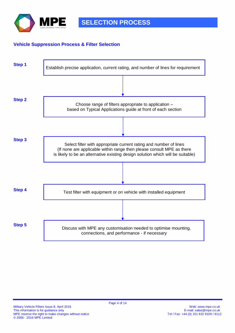
Vehicle Suppression Process & Filter Selection Step 1
Step 2
Step 3 Step 4 Step 5
Establish precise application, current rating, and number of lines for requirement
Choose range of filters appropriate to application –
based on Typical Applications guide at front of each section
Select filter with appropriate current rating and number of lines
(If none are applicable within range then please consult MPE as there is likely to be an alternative existing design solution which will be suitable)
Test filter with equipment or on vehicle with installed equipment
Discuss with MPE any customisation needed to optimise mounting,
connections, and performance - if necessary
Page 5 of 14 Military Vehicle Filters Issue 8, April 2016 Web: www.mpe.co.uk This information is for guidance only E-mail: [email protected]
MPE reserve the right to make changes without notice Tel / Fax: +44 (0) 151 632 9100 / 9112 © 2006 - 2016 MPE Limited
FILTER SOLUTION 1 - INDIVIDUALLY FILTERED LINES
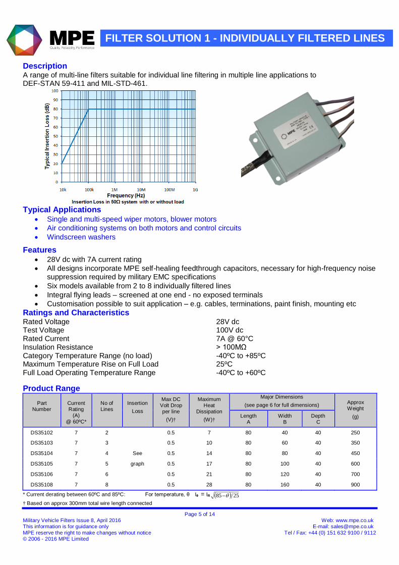
Description A range of multi-line filters suitable for individual line filtering in multiple line applications to DEF-STAN 59-411 and MIL-STD-461.
Typical Applications
Single and multi-speed wiper motors, blower motors
Air conditioning systems on both motors and control circuits
Windscreen washers
Features 28V dc with 7A current rating
All designs incorporate MPE self-healing feedthrough capacitors, necessary for high-frequency noise suppression required by military EMC specifications
Six models available from 2 to 8 individually filtered lines
Integral flying leads – screened at one end - no exposed terminals
Customisation possible to suit application – e.g. cables, terminations, paint finish, mounting etc
Ratings and Characteristics Rated Voltage 28V dc Test Voltage 100V dc Rated Current 7A @ 60°C Insulation Resistance > 100MΩ Category Temperature Range (no load) -40ºC to +85ºC Maximum Temperature Rise on Full Load 25ºC Full Load Operating Temperature Range -40ºC to +60ºC
Product Range
Part Number
Current Rating
(A)
@ 60ºC*
No of Lines
Insertion
Loss
Max DC Volt Drop per line
(V)†
Maximum Heat
Dissipation
(W)†
Major Dimensions
(see page 6 for full dimensions) Approx Weight
(g) Length A
Width B
Depth C
DS35102 7 2 0.5 7 80 40 40 250
DS35103 7 3 0.5 10 80 60 40 350
DS35104 7 4 See 0.5 14 80 80 40 450
DS35105 7 5 graph 0.5 17 80 100 40 600
DS35106 7 6 0.5 21 80 120 40 700
DS35108 7 8 0.5 28 80 160 40 900
* Current derating between 60ºC and 85ºC: For temperature, θ Iθ = IR 2585 † Based on approx 300mm total wire length connected
Page 6 of 14 Military Vehicle Filters Issue 8, April 2016 Web: www.mpe.co.uk This information is for guidance only E-mail: [email protected]
MPE reserve the right to make changes without notice Tel / Fax: +44 (0) 151 632 9100 / 9112 © 2006 - 2016 MPE Limited
FILTER SOLUTION 1 - INDIVIDUALLY FILTERED LINES
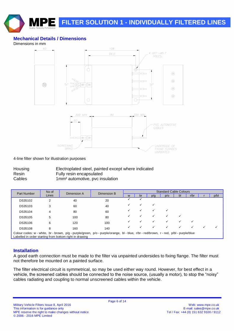
Mechanical Details / Dimensions
Dimensions in mm
4-line filter shown for illustration purposes
Housing Electroplated steel, painted except where indicated Resin Fully resin encapsulated Cables 1mm² automotive, pvc insulation
Part Number No of Lines
Dimension A Dimension B Standard Cable Colours
w br p/g p/o bl r/br r p/bl
DS35102 2 40 20
DS35103 3 60 40
DS35104 4 80 60
DS35105 5 100 80
DS35106 6 120 100
DS35108 8 160 140
Colour codes: w - white, br - brown, p/g - purple/green, p/o - purple/orange, bl - blue, r/br - red/brown, r - red, p/bl - purple/blue
Labelled in order starting from bottom right in drawing
Installation A good earth connection must be made to the filter via unpainted undersides to fixing flange. The filter must not therefore be mounted on a painted surface.
The filter electrical circuit is symmetrical, so may be used either way round. However, for best effect in a vehicle, the screened cables should be connected to the noise source, (usually a motor), to stop the “noisy” cables radiating and coupling to normal unscreened cables within the vehicle.
Page 7 of 14 Military Vehicle Filters Issue 8, April 2016 Web: www.mpe.co.uk This information is for guidance only E-mail: [email protected]
MPE reserve the right to make changes without notice Tel / Fax: +44 (0) 151 632 9100 / 9112 © 2006 - 2016 MPE Limited
FILTER SOLUTION 2 – PAIRED FILTERED LINES
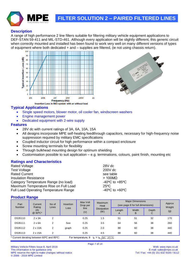
Description A range of high performance 2 line filters suitable for filtering military vehicle equipment applications to DEF-STAN 59-411 and MIL-STD-461. Although every application will be slightly different, this generic circuit when correctly mounted and installed has been found to work very well on many different versions of types of equipment where both dedicated + and – supplies are filtered, (ie not using chassis return).
Typical Applications Single speed motors, blower motor, oil cooler fan, windscreen washers
Engine management power
Dedicated equipment with 2-wire supply
Features 28V dc with current ratings of 3A, 6A, 10A, 15A
All designs incorporate MPE self-healing feedthrough capacitors, necessary for high-frequency noise suppression required by military EMC specifications
Coupled inductor circuit for high performance within a compact enclosure
Screw mounting terminals for flexibility
Through bulkhead mounting design for optimum shielding
Customisation possible to suit application – e.g. terminations, colours, paint finish, mounting etc
Ratings and Characteristics Rated Voltage 28V dc Test Voltage 200V dc Rated Current see table Insulation Resistance > 100MΩ Category Temperature Range (no load) -40ºC to +85ºC Maximum Temperature Rise on Full Load 25ºC Full Load Operating Temperature Range -40ºC to +60ºC
Product Range
Part Number
Current Rating
(A) @ 60ºC*
No of Lines
Insertion
Loss
Max Volt
Drop per line
(V)
Maximum
Heat Dissipation
(W)
Major Dimensions
(see page 8 for full dimensions) Approx
Weight
(g) Length
A
Width
B
Depth
C
DS35110 2 x 3A 2 0.25 1.5 51 51 32 170
DS35111 2 x 6A 2 See 0.25 3.5 64 56 38 260
DS35112 2 x 10A 2 graph 0.25 2.0 88 60 38 440
DS35113 2 x 15A 2 0.25 4.5 88 60 38 440
* Current derating between 60ºC and 85ºC: For temperature, θ Iθ = IR 2585
Page 8 of 14 Military Vehicle Filters Issue 8, April 2016 Web: www.mpe.co.uk This information is for guidance only E-mail: [email protected]
MPE reserve the right to make changes without notice Tel / Fax: +44 (0) 151 632 9100 / 9112 © 2006 - 2016 MPE Limited
FILTER SOLUTION 2 – PAIRED FILTERED LINES
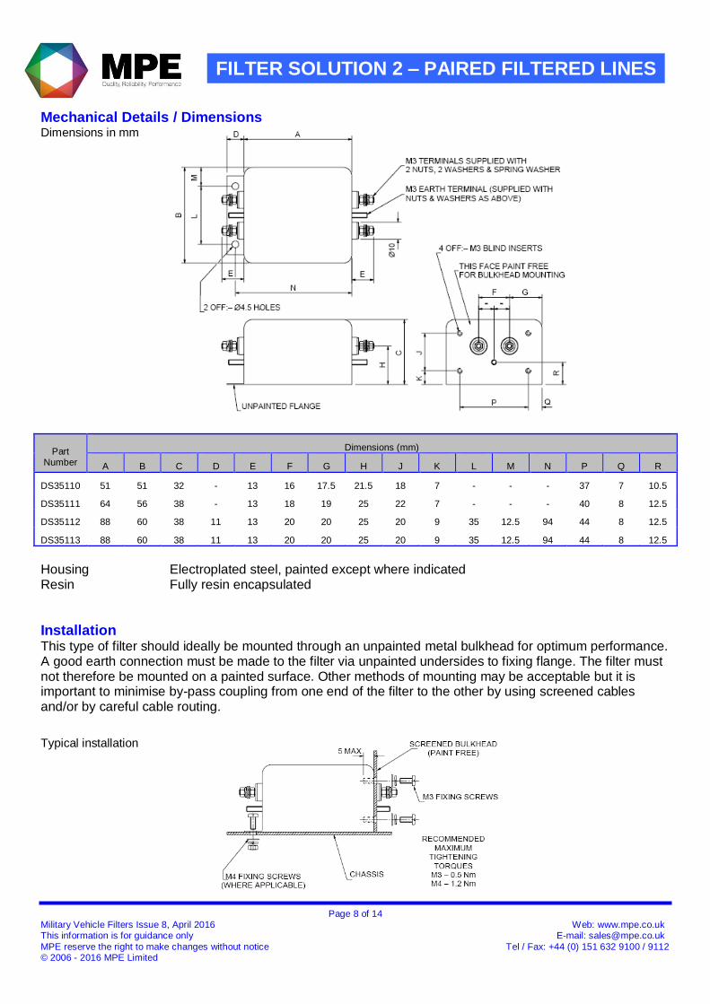
Mechanical Details / Dimensions Dimensions in mm
Part Number
Dimensions (mm)
A B C D E F G H J K L M N P Q R
DS35110 51 51 32 - 13 16 17.5 21.5 18 7 - - - 37 7 10.5
DS35111 64 56 38 - 13 18 19 25 22 7 - - - 40 8 12.5
DS35112 88 60 38 11 13 20 20 25 20 9 35 12.5 94 44 8 12.5
DS35113 88 60 38 11 13 20 20 25 20 9 35 12.5 94 44 8 12.5
Housing Electroplated steel, painted except where indicated Resin Fully resin encapsulated
Installation This type of filter should ideally be mounted through an unpainted metal bulkhead for optimum performance. A good earth connection must be made to the filter via unpainted undersides to fixing flange. The filter must not therefore be mounted on a painted surface. Other methods of mounting may be acceptable but it is important to minimise by-pass coupling from one end of the filter to the other by using screened cables and/or by careful cable routing.
Typical installation
Page 9 of 14 Military Vehicle Filters Issue 8, April 2016 Web: www.mpe.co.uk This information is for guidance only E-mail: [email protected]
MPE reserve the right to make changes without notice Tel / Fax: +44 (0) 151 632 9100 / 9112 © 2006 - 2016 MPE Limited
FILTER SOLUTION 3 – FEEDTHROUGH CAPACITORS
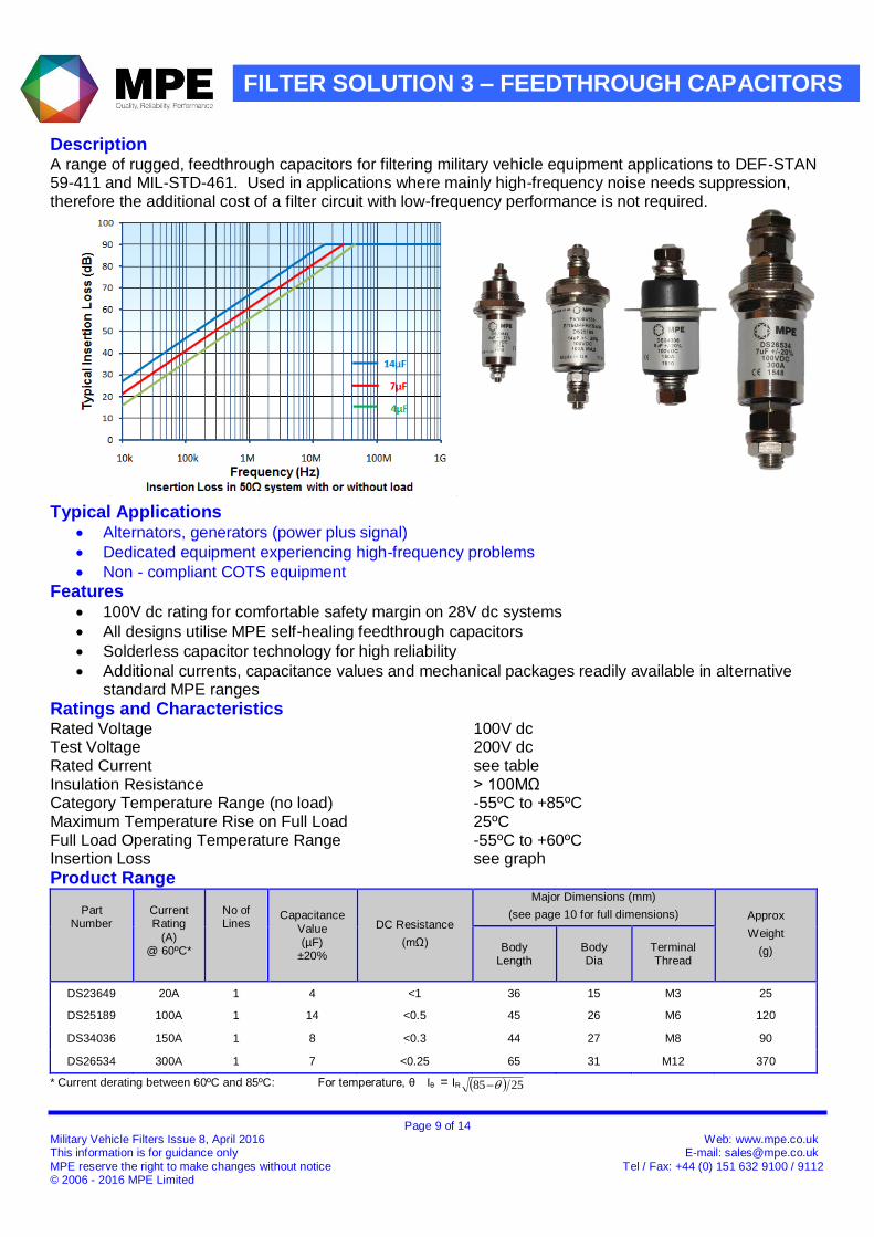
Description A range of rugged, feedthrough capacitors for filtering military vehicle equipment applications to DEF-STAN 59-411 and MIL-STD-461. Used in applications where mainly high-frequency noise needs suppression, therefore the additional cost of a filter circuit with low-frequency performance is not required.
Typical Applications
Alternators, generators (power plus signal)
Dedicated equipment experiencing high-frequency problems
Non - compliant COTS equipment
Features 100V dc rating for comfortable safety margin on 28V dc systems
All designs utilise MPE self-healing feedthrough capacitors
Solderless capacitor technology for high reliability
Additional currents, capacitance values and mechanical packages readily available in alternative standard MPE ranges
Ratings and Characteristics Rated Voltage 100V dc Test Voltage 200V dc Rated Current see table Insulation Resistance > 100MΩ Category Temperature Range (no load) -55ºC to +85ºC Maximum Temperature Rise on Full Load 25ºC Full Load Operating Temperature Range -55ºC to +60ºC Insertion Loss see graph
Product Range
Part Number
Current Rating
(A) @ 60ºC*
No of Lines
Capacitance
Value (µF)
±20%
DC Resistance
(mΩ)
Major Dimensions (mm)
(see page 10 for full dimensions) Approx
Weight
(g)
Body
Length
Body Dia
Terminal Thread
DS23649 20A 1 4 <1 36 15 M3 25
DS25189 100A 1 14 <0.5 45 26 M6 120
DS34036 150A 1 8 <0.3 44 27 M8 90
DS26534 300A 1 7 <0.25 65 31 M12 370
* Current derating between 60ºC and 85ºC: For temperature, θ Iθ = IR 2585
Page 10 of 14 Military Vehicle Filters Issue 8, April 2016 Web: www.mpe.co.uk This information is for guidance only E-mail: [email protected]
MPE reserve the right to make changes without notice Tel / Fax: +44 (0) 151 632 9100 / 9112 © 2006 - 2016 MPE Limited
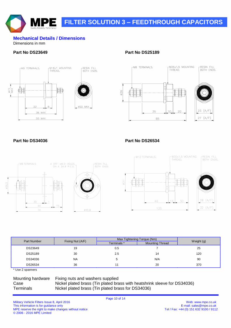
FILTER SOLUTION 3 – FEEDTHROUGH CAPACITORS
Mechanical Details / Dimensions Dimensions in mm
Part No DS23649 Part No DS25189
Part No DS34036 Part No DS26534
Part Number Fixing Nut (A/F) Max Tightening Torque (Nm)
Weight (g) Terminals * Mounting Thread
DS23649 19 0.5 7 25
DS25189 30 2.5 14 120
DS34036 NA 5 N/A 90
DS26534 36 11 20 370
* Use 2 spanners
Mounting hardware Fixing nuts and washers supplied Case Nickel plated brass (Tin plated brass with heatshrink sleeve for DS34036) Terminals Nickel plated brass (Tin plated brass for DS34036)
Page 11 of 14 Military Vehicle Filters Issue 8, April 2016 Web: www.mpe.co.uk This information is for guidance only E-mail: [email protected]
MPE reserve the right to make changes without notice Tel / Fax: +44 (0) 151 632 9100 / 9112 © 2006 - 2016 MPE Limited
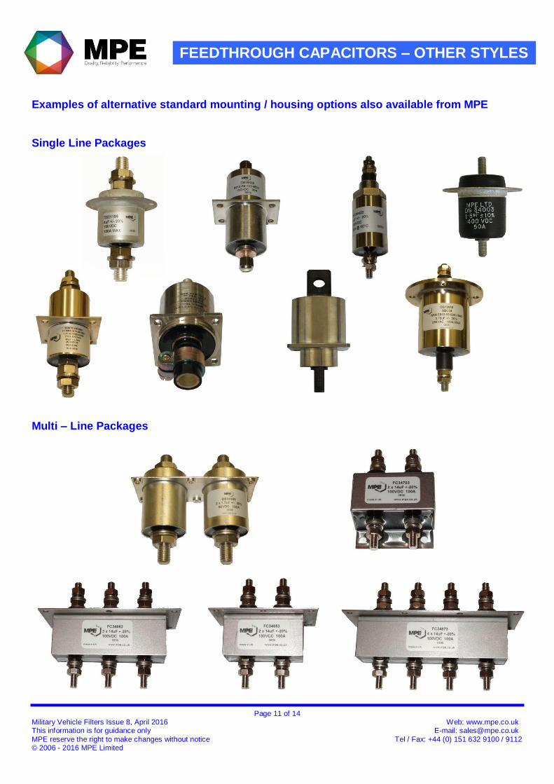
FEEDTHROUGH CAPACITORS – OTHER STYLES
Examples of alternative standard mounting / housing options also available from MPE
Single Line Packages
Multi – Line Packages
Page 12 of 14 Military Vehicle Filters Issue 8, April 2016 Web: www.mpe.co.uk This information is for guidance only E-mail: [email protected]
MPE reserve the right to make changes without notice Tel / Fax: +44 (0) 151 632 9100 / 9112 © 2006 - 2016 MPE Limited
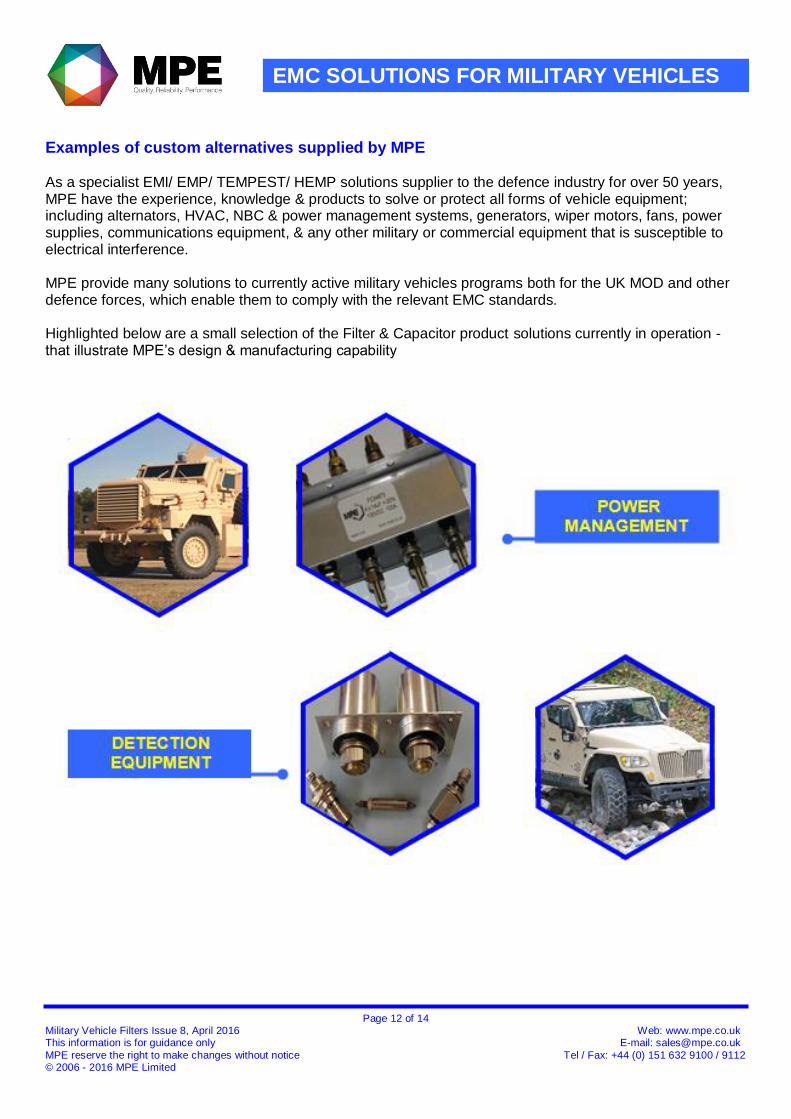
EMC SOLUTIONS FOR MILITARY VEHICLES
Examples of custom alternatives supplied by MPE As a specialist EMI/ EMP/ TEMPEST/ HEMP solutions supplier to the defence industry for over 50 years, MPE have the experience, knowledge & products to solve or protect all forms of vehicle equipment; including alternators, HVAC, NBC & power management systems, generators, wiper motors, fans, power supplies, communications equipment, & any other military or commercial equipment that is susceptible to electrical interference. MPE provide many solutions to currently active military vehicles programs both for the UK MOD and other defence forces, which enable them to comply with the relevant EMC standards. Highlighted below are a small selection of the Filter & Capacitor product solutions currently in operation - that illustrate MPE’s design & manufacturing capability
Page 13 of 14 Military Vehicle Filters Issue 8, April 2016 Web: www.mpe.co.uk This information is for guidance only E-mail: [email protected]
MPE reserve the right to make changes without notice Tel / Fax: +44 (0) 151 632 9100 / 9112 © 2006 - 2016 MPE Limited
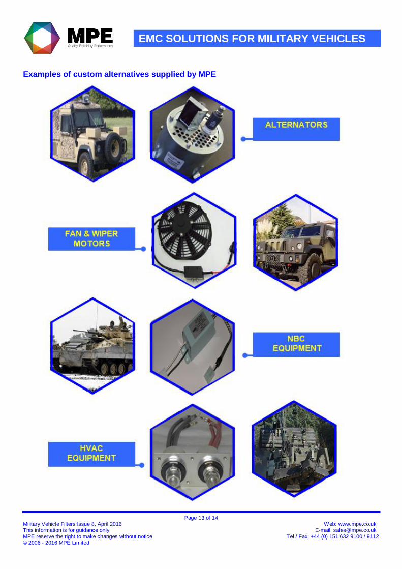
EMC SOLUTIONS FOR MILITARY VEHICLES
Examples of custom alternatives supplied by MPE

Page 14 of 14 Military Vehicle Filters Issue 8, April 2016 Web: www.mpe.co.uk This information is for guidance only E-mail: [email protected]
MPE reserve the right to make changes without notice Tel / Fax: +44 (0) 151 632 9100 / 9112 © 2006 - 2016 MPE Limited
INSTALLATION, BACKGROUND & SAFETY
General Installation Guidelines Feedthrough capacitors and filters designed for through-bulkhead mounting offer the best possible high frequency filtering in line-to-ground applications. They should be mounted through a metal bulkhead or chassis. The bulkhead mounting surface should be clean and unpainted to offer a low impedance path from the capacitor or filter to the equipment chassis. Poor earth bonding will limit the available performance of the product and in some applications could compromise safety. Conductive paint finishes should be avoided as they do not usually provide adequate conductivity. Two spanners should be used when making electrical connections to the terminals, and the maximum tightening torque figures quoted should be observed. Filters with leads permit remote mounting of filters where through- bulkhead mounting is not possible. The screened lead at one end prevents radiated noise on the incoming cables from radiating and coupling to either the filters unscreened output cables or to other unscreened cables in the vehicle. The screened leads should normally be connected to the noise source, such as a motor, and ideally the braid should be coaxially earthed at the noise source end, (as well as the filter), to provide a complete shield up to the noise source. Where this is not possible, the braid should be kept as long as possible to provide the maximum practical amount of shielding. It is essential to achieve a good earth connection to the case of the filter via the unpainted underside of its fixing flanges
Construction and Reliability MPE have been at the forefront of the design and manufacture of feedthrough capacitors and filter solutions for more than 40 years. The ongoing improvements in materials and assembly techniques, evolved throughout that period, have been incorporated into these ranges of filters and feedthrough capacitors. The designs covered by this catalogue all utilise self-healing metallised plastic film capacitor material and incorporate a solderless capacitor assembly technique wherever possible to avoid heat damage to the plastic dielectric material, which would reduce its life and reliability. Terminals are nickel plated for superior conductivity and tarnish resistance.
Safety Relevant safety standards have been adhered to in the design and manufacture of these products. However, all capacitors will store charge after power has been removed and must be treated with respect as this can be lethal when the voltage and charge are high enough. In all cases, filters should always be shorted to earth prior to touching terminals to ensure they are fully discharged. The user should ensure he is familiar with restrictions on capacitance value, earth leakage current, test voltage, and safety labelling requirements, which may be applicable to his particular installation. Filters must be solidly and permanently earthed, and terminals should be enclosed by the user where appropriate to avoid danger of electric shock.
RoHS Compliance
All filters in this brochure are RoHS compliant.
Custom Designs MPE offers a rapid design service for custom designs where special packaging, mounting, terminations, or multiple lines are required. Over 50% of the filters manufactured by MPE are custom designs which can also offer very cost effective installation solutions. Please contact the MPE sales team to discuss your application or specification requirements, as alternative, proven solutions can also be offered from our extensive technical design database.
Further Information For more detailed technical background information, and application notes concerning the benefits of filters containing feedthrough capacitors, please visit our web site or contact the MPE sales team.