Embed Size (px)
Citation preview

Mitsubishi Electric AC Servo System
J
EMC InstallationGuidelines

1
CONTENTS
1. SUMMARY 1 - 1 to 1 - 2
2. EMC DIRECTIVE 2 - 1 to 2 - 2
3. EMC COUNTERMEASURES 3 - 1 to 3 -10
3.1 Basic EMC countermeasures .................................................................................................................. 3 - 1
3.2 Cabinet design ......................................................................................................................................... 3 - 1
3.3 Filter wiring and installation ...................................................................................................................... 3 - 4
3.4 Cable treatment ........................................................................................................................................ 3 - 6
4. EMC COUNTERMEASURE PARTS 4 - 1 to 4 - 12
4.1 Noise filter (For controller power supply) ................................................................................................. 4 - 1
4.2 EMC filter (For servo amplifier power supply) ......................................................................................... 4 - 1
4.3 Ferrite core (Data line filter) ..................................................................................................................... 4 - 7
4.4 Shield clamp fitting ................................................................................................................................... 4 - 8
4.5 Line noise filter ......................................................................................................................................... 4 - 8
4.5.1 Connection example ......................................................................................................................... 4 - 8
4.5.2 Precautions ....................................................................................................................................... 4 -10
4.6 Surge protector ........................................................................................................................................ 4 -11
5. CONNECTION EXAMPLE FOR EMC COUNTERMEASURES 5 - 1 to 5 - 4
5.1 For 22kW or less of 1-axis ....................................................................................................................... 5 - 1
5.2 For 1kW or less of multi axis .................................................................................................................... 5 - 2
5.3 For 30kW or more .................................................................................................................................... 5 - 3
6. SUPPLEMENT 6 - 1 to 6 - 6
6.1 Reasons why the shield is grounded on both the cabinet side and the servo motor chassis side ....... 6 - 1
6.1.1 Grounding the shield at the servo amplifier side only ...................................................................... 6 - 1
6.1.2 Grounding the shield at both ends of the cable................................................................................ 6 - 2
6.2 Reasons why the grounding position in the cabinet is specified to be 10 cm or less from the
cabinet exit ............................................................................................................................................... 6 - 3

2
6.3 Reasons why the shield must be grounded with the P clip or U clip ...................................................... 6 - 3
6.4 Connecting multiple servo amplifiers to one EMC filter (1: n connection) ............................................. 6 - 4
6.4.1 Selection method ............................................................................................................................... 6 - 4
6.4.2 Selection example ............................................................................................................................. 6 - 5

1 - 1
1. SUMMARY
1. SUMMARY
We have carried out EMC standard compliance confirmation tests with the servo amplifier in the installation
environment described in this manual. After incorporating the servo amplifier in the machine or equipment,
confirm the EMC standard compliance of the entire machine or equipment on customer side.
For the EMC countermeasures, refer to this guideline or the instruction manual of the servo amplifier used.

1 - 2
1. SUMMARY
MEMO

2 - 1
2. EMC DIRECTIVE
2. EMC DIRECTIVE
Mitsubishi Electric general-purpose AC servo MELSERVO complies with products standard EN 61800-3. This directive largely regulates the following two withstand levels. (1) Emission (EMI: Electromagnetic Interference)
Capacity to prevent output of obstructive noise that adversely affects external sources. (2) Immunity (EMS: Electromagnetic Susceptibility)
Capacity to not malfunction due to obstructive noise from external source. The details of each level are classified below.
Class Name Details Products standard
Emission (EMI)
Radiated noise Electromagnetic noise radiated through the air, etc.
EN 61800-3
Conducted noise Electromagnetic noise discharged from power supply line, etc.
Immunity (EMS)
Electrostatic discharge immunity test IEC 61000-4-2
Noise from a charged human body, etc.
Radiated, radio-frequency, electromagnetic field immunity test IEC 61000-4-3
Electromagnetic noise from wireless transmitters or broadcasting companies, etc.
Electrical fast transient/burst immunity test IEC 61000-4-4
Relay noise or electromagnetic noise caused by live electricity being turned on or off, etc.
Immunity to conducted disturbances, induced by radio-frequency fields IEC 61000-4-6
Electromagnetic noise flowed from power supply wires or earthing wires, etc.
Power-frequency magnetic field immunity test IEC 61000-4-8
Electromagnetic noise of 50/60Hz power supply frequency, etc.
Voltage dips, short interruptions and voltage variations immunity tests IEC 61000-4-11
Power supply drop, etc.
Surge immunity test IEC 61000-4-5
Electromagnetic conducted noise discharged by thunder, etc.

2 - 2
2. EMC DIRECTIVE
MEMO

3 - 1
3. EMC COUNTERMEASURES
3. EMC COUNTERMEASURES
CAUTION
The servo amplifier must be installed in the metal cabinet.
3.1 Basic EMC countermeasures
POINT
According to the NFPA79 approved by the United States, when the shielded
wire is not used for wiring between a servo amplifier and a servo motor, the
wiring must be insulated from wiring of other control or signal circuits.
(Example: 100 mm or more for 20 A or less)
Take the following measures firmly as EMC countermeasures.
(1) Install the device in a sealed metal cabinet.
(2) Install a noise filter.
(3) Accurately earth the device.
(4) Use shielded wires for cables and wires.
(5) Separate the primary-side wiring and the secondary-side wiring as far as possible.
(6) Install the surge protector. (Refer to section 4.6.)
3.2 Cabinet design
The servo is a complex component incorporated into another machine. It must always be installed in a cabinet.
The design of the cabinet is a very important factor for EMC countermeasures, so please take the following
points into consideration.
(1) Use a metal cabinet.
(2) Accurately earth the cabinet unit with a thick and short cable.
3 - 2
3. EMC COUNTERMEASURES
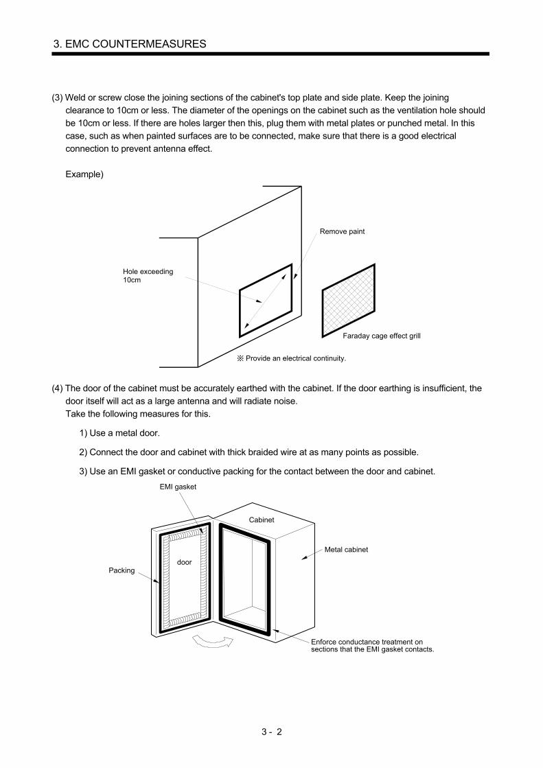
(3) Weld or screw close the joining sections of the cabinet's top plate and side plate. Keep the joining
clearance to 10cm or less. The diameter of the openings on the cabinet such as the ventilation hole should
be 10cm or less. If there are holes larger then this, plug them with metal plates or punched metal. In this
case, such as when painted surfaces are to be connected, make sure that there is a good electrical
connection to prevent antenna effect.
Example)
Remove paint
Hole exceeding10cm
Faraday cage effect grill
Provide an electrical continuity.
(4) The door of the cabinet must be accurately earthed with the cabinet. If the door earthing is insufficient, the
door itself will act as a large antenna and will radiate noise.
Take the following measures for this.
1) Use a metal door.
2) Connect the door and cabinet with thick braided wire at as many points as possible.
3) Use an EMI gasket or conductive packing for the contact between the door and cabinet.
Cabinet
Metal cabinet
Enforce conductance treatment onsections that the EMI gasket contacts.
EMI gasket
Packingdoor

3 - 3
3. EMC COUNTERMEASURES
(5) To take preventive measures against the noise of the input power source cable in the cabinet, install the
shielding partition at nearby site where the power is input so that the input power cable does not receive
harmful effects of the radiated noise.
AC input
Filter MCCB
Radiated noise
Cabinet
AC input
Filter MCCB
Radiated noise
Shieldingpartition
Controller Servo amplifier Controller Servo amplifier
Cabinet
The power supply line noise iseliminated by the filter, but cablecontains noise again because of thenoise radiated in the cabinet.
Use a metal plate, etc., for theshielding partition.Make sure there are no gaps.

3 - 4
3. EMC COUNTERMEASURES
3.3 Filter wiring and installation
POINT
For when multiple servo amplifiers are connected to one EMC filter, refer to
section 6.4.
(1) Wire the servo and filter as shown below.
Powersupply
Molded-casecircuit
breaker
EMCfilter
Magneticcontactor
Servo amplifier
Control circuitpower supply
Main circuitpower supply
Servomotor
Wiring length 1.5m or less (recommended)
(2) Arrange the EMC filter input cable and output cable as far apart as possible. If they are too close, the output
line noise will be induced into the input cable, and effect of the filter will be lost. Separate these cables by at
least 30cm or more.
EMCfilter
EMCfilter
Input(power supply side)
Output(servo amplifier side)
OK NG
Input(power supply side)
Output(servo amplifier side)
The output side noise is induced to the input side.

3 - 5
3. EMC COUNTERMEASURES
(3) Installation of filter.
Install the servo amplifier and EMC filter on the same cabinet.
Install the filter on the right or left side of the servo amplifier, as shown below.
(For details of the EMC filter, refer to section 4.2.)
The surface inside the cabinet where the filter is to be installed must be bare metal or metal plated surface
so that the rear surface of the filter electrically contacts the cabinet. Treat the surface where the servo
amplifier is installed in the same manner. The filter input wire (a) must be kept as far apart from the output
wires (b), (c) and (d). Keep the wiring ((b), (c), (d)) between the filter and servo amplifier as short as
possible.
(The sum of (b) and (c) is 1.5m or less.)
Cabinet
Servo amplifier
Filter
Bare metal ormetal platedsurface(no paint, etc)
Control circuitpower supply
Main circuitpower supply
Powersupplyinput
(b)
(c)
(d)
(a)
Magneticcontactor

3 - 6
3. EMC COUNTERMEASURES
3.4 Cable treatment
(a) Securely earth the cabinets 1 and 2, and the servo motor.
(b) Keep the main circuit power supply cable of the servo amplifier, power cable of the servo motor, and
wire for the control circuit signal apart (30 cm or more). These cables must not be routed in close parallel
or bundled.
The following drawing shows an example of the installation.
The methods for treating each cable are described separately.
(The numbers assigned to each cable in the drawing indicate section number of this manual where details are
explained.)
Servo motor
Encoder
Section 3.4(1)
Servo amplifierControllerPower supply
Section 3.4(2)
EMC filter
Section 3.4(7)
Section 3.4(4)
Section 3.4(3)
Controller, etc.
Cabinet 2
Cabinet 1
Magneticcontactor
Section3.4(3)
Option
24VDCpowersupply
Surge protector
3 - 7
3. EMC COUNTERMEASURES
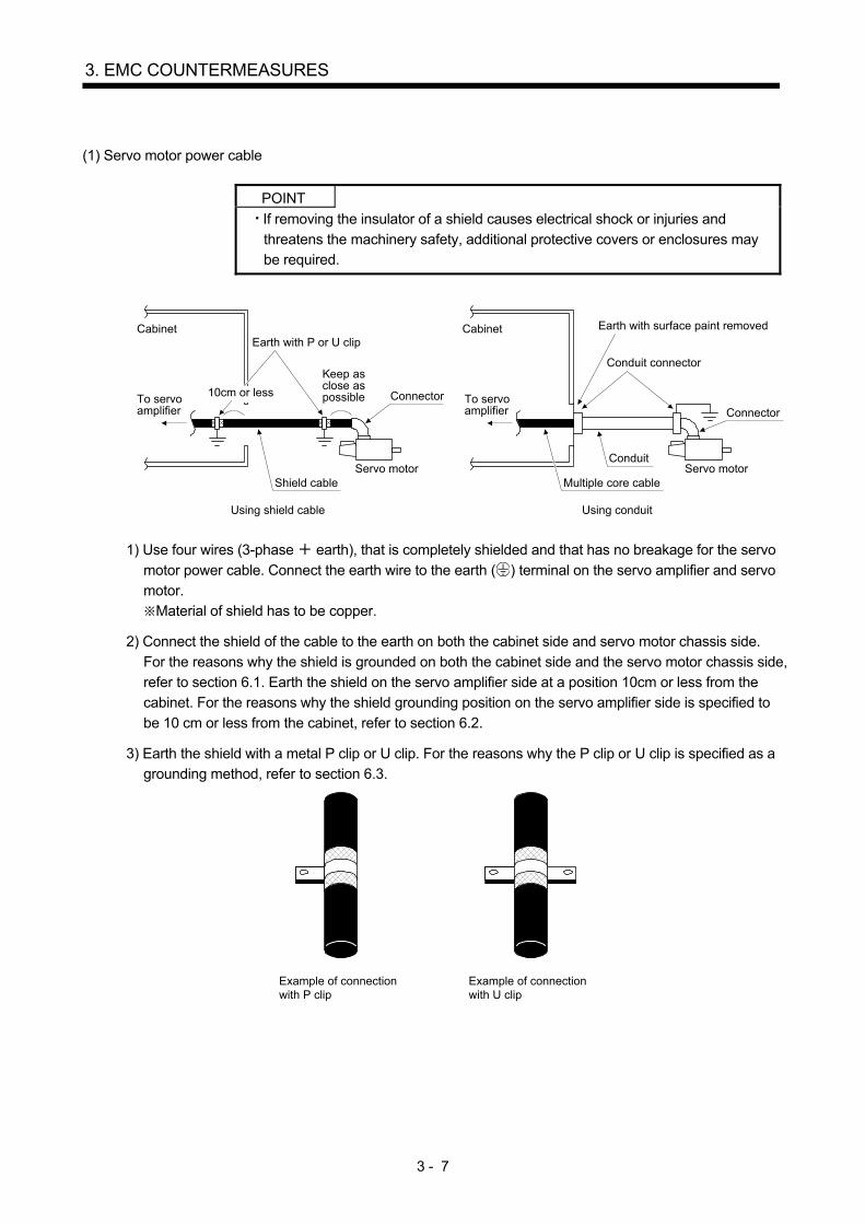
(1) Servo motor power cable
POINT
If removing the insulator of a shield causes electrical shock or injuries and
threatens the machinery safety, additional protective covers or enclosures may be required.
Cabinet
To servoamplifier
Using shield cable
Shield cableServo motor
Connector
Earth with P or U clip
Conduit connector
Multiple core cableServo motor
Earth with surface paint removedCabinet
To servoamplifier Connector
Conduit
Using conduit
Keep asclose aspossible10cm or less
1) Use four wires (3-phase earth), that is completely shielded and that has no breakage for the servo
motor power cable. Connect the earth wire to the earth ( ) terminal on the servo amplifier and servo
motor.
Material of shield has to be copper.
2) Connect the shield of the cable to the earth on both the cabinet side and servo motor chassis side.
For the reasons why the shield is grounded on both the cabinet side and the servo motor chassis side,
refer to section 6.1. Earth the shield on the servo amplifier side at a position 10cm or less from the
cabinet. For the reasons why the shield grounding position on the servo amplifier side is specified to
be 10 cm or less from the cabinet, refer to section 6.2.
3) Earth the shield with a metal P clip or U clip. For the reasons why the P clip or U clip is specified as a
grounding method, refer to section 6.3.
Example of connectionwith P clip
Example of connectionwith U clip

3 - 8
3. EMC COUNTERMEASURES
4) Directly earth the shield. It is not recommended to solder the wire to the braided wire (shield) and
ground with its end.
Example of earthingwith wire soldering
Solder
5) When not using a shield cable for the servo motor power cable, put the cable into a metal conduit.
6) Earth the servo motor power cable on the cabinet side with the conduit connector and cabinet side
wall. (Remove paint from the side wall of the cabinet.)
7) When grounding the servo motor power cable connected to the servo motor, take the following
measure by fixing the cable cramp to the conduit connector shown in the following drawing.
Clamp fitting
Conduit
Conduit connector Connector
To earth (Use as thick and short wire as possible)
8) Keep the cable length at 50m or less.
(2) Encoder cable
Cabinet
To servoamplifier
Shield twisted pair cable
ConnectorAs close aspossible
10cm or less
Use a shielded twisted pair cable, and earth on the servo amplifier and encoder side with a P clip or U clip.
Keep the cable length at 50m or less.
3 - 9
3. EMC COUNTERMEASURES
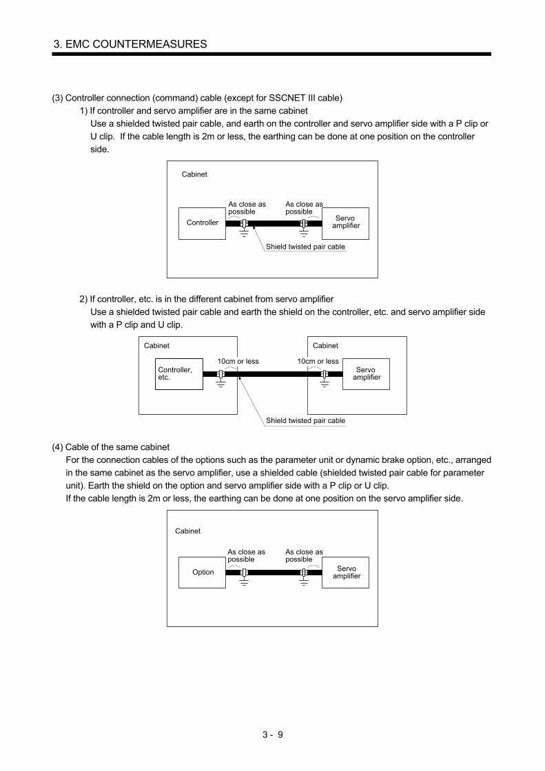
(3) Controller connection (command) cable (except for SSCNET III cable)
1) If controller and servo amplifier are in the same cabinet
Use a shielded twisted pair cable, and earth on the controller and servo amplifier side with a P clip or
U clip. If the cable length is 2m or less, the earthing can be done at one position on the controller
side.
As close aspossible
ServoamplifierController
Cabinet
Shield twisted pair cable
As close aspossible
2) If controller, etc. is in the different cabinet from servo amplifier
Use a shielded twisted pair cable and earth the shield on the controller, etc. and servo amplifier side
with a P clip and U clip.
Controller,etc.
Cabinet
Servoamplifier
Cabinet
10cm or less
Shield twisted pair cable
10cm or less
(4) Cable of the same cabinet
For the connection cables of the options such as the parameter unit or dynamic brake option, etc., arranged
in the same cabinet as the servo amplifier, use a shielded cable (shielded twisted pair cable for parameter
unit). Earth the shield on the option and servo amplifier side with a P clip or U clip.
If the cable length is 2m or less, the earthing can be done at one position on the servo amplifier side.
As close aspossible
ServoamplifierOption
Cabinet
As close aspossible

3 - 10
3. EMC COUNTERMEASURES
(5) Regenerative option connection cable
For the regenerative option cable, use a twisted cable with shield or a twisted cable covered with shield
braid. Earth the shield on the option and servo amplifier with a P clip or U clip. The drawing shows the
treatment for when the regenerative option is installed outside the cabinet.
As close aspossible
Regenerativeoption
Cabinet
10cm or less
Shield braid
Servoamplifier
Twisted cable
(6) Input power supply cable
Use the conventional multiple core cable.
Using shielded input power cables increases the effect of EMC countermeasures.
(7) 24VDC cable (for servo amplifier)
Use a vinyl wire or multiple core cable.

4 - 1
4. EMC COUNTERMEASURE PARTS
4. EMC COUNTERMEASURE PARTS
This chapter explains parts used in EMC countermeasures. For details of the parts, contact the parts manufacturer. 4.1 Noise filter (For controller power supply)
For the noise filter installed to the controller, refer to the manual of the controller used. 4.2 EMC filter (For servo amplifier power supply)
POINT For connection with servo amplifiers, refer to each servo amplifier instruction manual. For when multiple servo amplifiers are connected to one EMC filter, refer to section 6.4.
It is recommended to use the following filter. Some EMC filters are large in leakage current. Some EMC filters for servo amplifiers of special specifications (such as RJ, ED, PX, RU, and RZ) are also large in leakage current. Select a molded-case circuit breaker in considering the increase of leakage current, so that the leakage current does not affect servo amplifiers, converter units and drive units. Refer to instruction manuals of each product for the products other than series described in this section.

4 - 2
4. EMC COUNTERMEASURE PARTS
(1) Combination of 22kW or less servo amplifiers and filters
(a) For MR-J5 series 1) Manufactured by COSEL Co., Ltd.
Servo amplifier Recommended filter/Operating temperature range: -40 °C to 85 °C (Category
C2, C3 (Note)) Mass [kg]
Model Rated current [A] Rated voltage [VAC] MR-J5-10 to MR-J5-100 MR-J5W2-22G MR-J5W2-44G MR-J5W3-222G
FSB-10-254-HU 10
500 1.8 FSB-20-254-HU 20
FSB-30-254-HU 30
MR-J5-200 , MR-J5-350 MR-J5W2-77G, MR-J5W2-1010G MR-J5W3-444G
FSB-30-254-HU 30 500 1.8
Note. Category C2: First environment (residential and other environments) and second environment (commercial, light industrial,
and industrial environments) Category C3: Second environment (commercial, light industrial, and industrial environments)
2) Manufactured by Soshin Electric Co., Ltd.
Servo amplifier Recommended filter/Operating temperature range: -20 °C to 50 °C (Category
C3 (Note)) Mass [kg]
Model Rated current [A] Rated voltage [VAC]
MR-J5-10 to MR-J5-100 HF3010C-SZB 10
500 0.9
HF3020C-SZB 20 1.3 HF3030C-SZB 30 1.3
MR-J5-200 , MR-J5-350 MR-J5W2-77G, MR-J5W2-1010G MR-J5W3-444G
HF3030C-SZB 30 500 1.3
Note. Category C3: Second environment (commercial, light industrial, and industrial environments)
(b) For MR-J4 series
Servo amplifier Recommended filter (SOSHIN Electric Co., Ltd)
Mass [kg] ([lb]) Model
Rated current [A]
Rated voltage [VAC]
Leakage current [mA]
MR-J4-10 to MR-J4-100 MR-J4W2-22B MR-J4W3-222B
HF3010A-UN (Note) 10
250 5
3.5 (7.72) MR-J4W2-44B HF3010A-UN2 (Note) MR-J4-200 MR-J4-350 MR-J4W2-77B MR-J4W2-1010B MR-J4W3-444B
HF3030A-UN (Note) 30 5.5 (12.13)
MR-J4-500 MR-J4-700 HF3040A-UN (Note) 40 6.5
6 (13.23) MR-J4-11K to MR-J4-22K HF3100A-UN (Note) 100 12 (26.46) MR-J4-60 4 MR-J4-100 4 TF3005C-TX 5
6 (13.23) MR-J4-200 4 to MR-J4-700 4 TF3020C-TX 20 MR-J4-11K 4 TF3030C-TX 30 500 5.5 7.5 (16.54) MR-J4-15K 4 TF3040C-TX 40
12.5 (27.56) MR-J4-22K 4 TF3060C-TX 60 MR-J4-10 1 to MR-J4-40 1 HF3010A-UN (Note) 10 250 5 3.5
Note. A surge protector is separately required to use any of these EMC filters. (Refer to section 4.6.)

4 - 3
4. EMC COUNTERMEASURE PARTS
Servo amplifier Recommended filter (COSEL Co., Ltd)
Mass [kg] ([lb]) Model
Rated current [A]
Rated voltage [VAC]
Leakage current [mA]
MR-J4-11K to MR-J4-22K FTB-100-355-L (Note) 100 500 40 5.3 (11.69) MR-J4-22K 4 FTB-80-355-L (Note) 80 500 80 5.3 (11.69)
Note. A surge protector is separately required to use any of these EMC filters. (Refer to section 4.6.)
(c) For MR-JN series
Servo amplifier Recommended filter (SOSHIN Electric Co., Ltd)
Mass [kg] ([lb]) Model
Rated current [A]
Rated voltage [VAC]
Leakage current [mA]
MR-JN-10A(1) to MR-JN-20A(1) MR-JN-40A
HF3010A-UN (Note) 10 250 5 3.5 (7.72)
Note. A surge protector is separately required to use any of these EMC filters. (Refer to section 4.6.)
(d) For MR-J3W series
Servo amplifier Recommended filter (SOSHIN Electric Co., Ltd)
Mass [kg] ([lb]) Model
Rated current [A]
Rated voltage [VAC]
Leakage current [mA]
MR-J3W-22B MR-J3W-44B HF3010A-UN (Note) 10 250 5
3.5 (7.72) MR-J3W-77B MR-J3W-1010B HF3030A-UN (Note) 30 5.5 (12.13)
Note. A surge protector is separately required to use any of these EMC filters. (Refer to section 4.6.)
(e) For MR-J3 series
Servo amplifier Recommended filter (SOSHIN Electric Co., Ltd)
Mass [kg] ([lb]) Model
Rated current [A]
Rated voltage [VAC]
Leakage current [mA]
MR-J3-10 to MR-J3-100 MR-J3-10 1 to MR-J3-40 1
HF3010A-UN (Note) 10 5
3.5 (7.72)
MR-J3-200 MR-J3-350 HF3030A-UN (Note) 30 250 5.5 (12.13) MR-J3-500 MR-J3-700 HF3040A-UN (Note) 40
6.5 6.0 (13.23)
MR-J3-11K to MR-J3-22K HF3100A-UN (Note) 100 12 (26.46) MR-J3-60 4 MR-J3-100 4 TF3005C-TX 5
6.0 (13.23) MR-J3-200 4 to MR-J3-700 4 TF3020C-TX 20 MR-J3-11K 4 TF3030C-TX 30 500 5.5 7.5 (16.54) MR-J3-15K 4 TF3040C-TX 40
12.5 (27.56) MR-J3-22K 4 TF3060C-TX 60
Note. A surge protector is separately required to use any of these EMC filters. (Refer to section 4.6.)

4 - 4
4. EMC COUNTERMEASURE PARTS
(f) For MR-J2-Super series
POINT The production of the MR-J2-Super series was discontinued in August 2015.
Servo amplifier Recommended filter (DEM Manufacturing Ltd.)
Mass [kg] ([lb]) Model
Rated current [A]
Rated voltage [VAC]
Leakage current [mA]
MR-J2S-10 to MR-J2S-100 MR-J2S-10 1 to MR-J2S-40 1
SF1252 10.5 250
38 0.75 (1.65)
MR-J2S-200 MR-J2S-350 SF1253 27.5 57 1.37 (3.02)
Servo amplifier Recommended filter (SOSHIN Electric Co., Ltd)
Mass [kg] ([lb]) Model
Rated current [A]
Rated voltage [VAC]
Leakage current [mA]
MR-J2S-500 HF3040A-TM (Note) 40 1.5
5.5 (12.13) MR-J2S-700 HF3050A-TM (Note) 50 6.7 (14.77) MR-J2S-11K HF3060A-TMA (Note) 60 250 10.0 (22.05) MR-J2S-15K HF3080A-TMA (Note) 80 3.0 13.0 (28.66) MR-J2S-22K HF3100A-TMA (Note) 100 14.5 (31.97) MR-J2S-60 4 to MR-J2S-200 4 TF3005C-TX 5
6 (13.23) MR-J2S-350 4 to MR-J2S-700 4 TF3020C-TX 20 MR-J2S-11K 4 TF3030C-TX 30 500 5.5 7.5 (16.54) MR-J2S-15K 4 TF3040C-TX 40
12.5 (27.56) MR-J2S-22K 4 TF3060C-TX 60
Note. A surge protector is separately required to use any of these EMC filters. (Refer to section 4.6)

4 - 5
4. EMC COUNTERMEASURE PARTS
(2) Combination of 30kW or more converter unit, drive unit and filter
(a) For MR-J4 series
Converter unit Drive unit Recommended filter (SOSHIN Electric Co., Ltd)
Mass [kg] ([lb]) Model Rated current
[A] Rated voltage
[VAC] Leakage
current [mA]
MR-CR55K MR-J4-DU30K MR-J4-DU37K
HF3200A-UN (Note) 200 250 9 18
(39.68)
MR-CR55K4
MR-J4-DU30K 4 MR-J4-DU37K 4 MR-J4-DU45K 4 MR-J4-DU55K 4
TF3150C-TX 150 500 5.5 31 (68.34)
Note. A surge protector is separately required to use any of these EMC filters. (Refer to section 4.6.)
Converter unit Drive unit Recommended filter (COSEL Co., Ltd) Mass
[kg] ([lb]) Model Rated current [A]
Rated voltage [VAC]
Leakage current [mA]
MR-CR55K4
MR-J4-DU30K 4 MR-J4-DU37K 4 MR-J4-DU45K 4 MR-J4-DU55K 4
FTB-150-355-L (Note)
150 500 80 7.8 (17.12)
Note. A surge protector is separately required to use any of these EMC filters. (Refer to section 4.6.)
(b) For MR-J3 series
Converter unit Drive unit Recommended filter (SOSHIN Electric Co., Ltd)
Mass [kg] ([lb]) Model
Rated current [A]
Rated voltage [VAC]
Leakage current [mA]
MR-J3-CR55K MR-J3-DU30K MR-J3-DU37K
HF3200A-UN (Note)
200 250 9 18
(39.68)
MR-J3-CR55K4 MR-J3-DU30K 4 to MR-J3-DU55K 4
TF3150C-TX 150 500 5.5 31
(68.34) Note. A surge protector is separately required to use any of these EMC filters. (Refer to section 4.6.)
(c) For MR-J2-Super series
POINT The production of the MR-J2-Super series was discontinued in August 2015.
Converter unit Drive unit Recommended filter (SOSHIN Electric Co., Ltd)
Mass [kg] ([lb]) Model
Rated current [A]
Rated voltage [VAC]
Leakage current [mA]
MR-HP30KA MR-J2S-30K MR-J2S-37K
HF3200A-TMA (Note)
200 250 3 23.5
(51.81)
MR-HP55KA4 MR-J2S-30K 4 to MR-J2S-45K 4 TF3150C-TX 150 500 5.5
31 (68.34)
MR-J2S-55K 4 Note. A surge protector is separately required to use any of these EMC filters. (Refer to section 4.6.)

4 - 6
4. EMC COUNTERMEASURE PARTS
(3) Combination of a simple converter and filters
If the total length of a servo motor power cable is 50 m or less, select a filter recommended in section 4.2 (1) (a) 1). If the total length of the servo motor power cable is more than 50 m, select a filter which satisfies the following conditions. EMC filter rated current [A] ≥ Total rated input current of all servo amplifiers to be connected [A] Total length of servo motor power cables supported by the EMC filter [m] ≥
Total length of all servo motor power cables to be connected [m]
Simple converter
Total length of servo motor power cable [m]
Recommended filter (SOSHIN Electric Co., Ltd.)/Operating temperature range: -20 °C to 50 °C (Category C3 (Note))
Mass [kg]
Model Rated current [A] Rated voltage [V]
MR-CM3K
100 or less HF3030C-SZL 30
500
1.3 200 or less HF3060C-SZL 60 2.1 250 or less HF3100C-SZL 100 5.8 250 or less HF3150C-SZL 150 9.0
Note. Category C3: Second environment (commercial, light industrial, and industrial environments)

4 - 7
4. EMC COUNTERMEASURE PARTS
[SF1252, SF1253 wire connection method]
Flat bladed screwdriver
Wire
1) Peel the wire insulator. CoreInsulator
9mm Core length for SF1252 14mm Core length for SF1253
2) Insert the core of the cable into the opening, and tighten with the slotted screwdriver. In addition, connect the cables to the terminals of SF1252 or SF1253 in a one-to-one connection.
EMC filter Screw size Tightening torque SF1252 2.5mm 0.598N m SF1253 3mm 0.794N m
4.3 Ferrite core (Data line filter)
Noise can be prevented by installing a data line filter onto the cables connected to the servo amplifier. The data line filter in the following is one such example.
Model (Note) Impedance ( ) ZCAT3035-1330 10 to 100MHz 100 to 500MHz
(Manufactured by TDK) 80 150 Note. The above values of impedance do not refer to the guaranteed values but the impedance values of the data line filter
including those of the cable (measured reference values). ESD-SR-250 by NEC TOKIN, E04SRM563218 by SEIWA ELECTRIC, etc. are also available.
[Usage example]
Passing through once Passing through twice Passing through three times

4 - 8
4. EMC COUNTERMEASURE PARTS
4.4 Shield clamp fitting
Generally, the earth of the shielded cable may only be connected to the connector’s SD terminal. However, the effect can be increased by directly connecting the cable to an earth plate as shown below. Install the earth plate near the servo amplifier for the encoder cable. Peel part of the cable insulator tot expose the external conductor, and press that part against the earth plate with the cable clamp. If the cable is thin, clamp several cables in bunch. The clamp comes as a set with the earth plate.
Strip the cable insulator ofthe clamp area
Cable
Cable
Clamp section diagramExternal conductor
Earth plateCable clamp
Cutter
Model Accessory fittings AERSBAN-DSET 2 cable cramps AERSBAN-ESET 1 cable cramp
4.5 Line noise filter
The line noise filter is effective in suppressing noises radiated from the cables connected to the main circuit power in the servo amplifier (converter unit) and those connected to the servo amplifier power output, and also in suppressing high-frequency leakage current (zero-phase current) especially within 0.5MHz to 5MHz band. 4.5.1 Connection example
The line noise filters are used for the cables connected to (L1, L2, and L3) the main circuit power supply and for those connected to (U, V, and W) the servo amplifier power output. Pass each of 3-phase cables through line noise filters an equal number of times in the same direction. (1) For use of 1 line noise filter
Powersupply
L3
L2
L1
Servo amplifier(Converter unit)
(4 times pass)
4 - 9
4. EMC COUNTERMEASURE PARTS
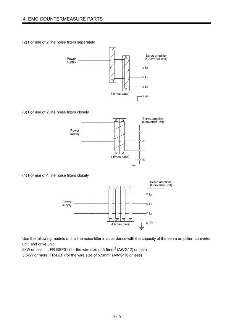
(2) For use of 2 line noise filters separately
Powersupply
L3
L2
L1
Servo amplifier(Converter unit)
(4 times pass)
(3) For use of 2 line noise filters closely
Powersupply
L3
L2
L1
Servo amplifier(Converter unit)
(4 times pass)
(4) For use of 4 line noise filters closely
Powersupply
L3
L2
L1
Servo amplifier(Converter unit)
(4 times pass)
Use the following models of the line noise filter in accordance with the capacity of the servo amplifier, converter unit, and drive unit. 2kW or less : FR-BSF01 (for the wire size of 3.5mm2 (AWG12) or less) 3.5kW or more: FR-BLF (for the wire size of 5.5mm2 (AWG10) or less)

4 - 10
4. EMC COUNTERMEASURE PARTS
4.5.2 Precautions
(1) When the line noise filter is used for the main circuit power side in the servo amplifier (converter unit), the effect of the filters is produced as the number of passes increases. The appropriate number of passage is four times.
(2) When using the line noise filter for the cable connected to the servo amplifier power output, pass through
four times or less. (3) Do not pass the earth wire through the line noise filter. Doing so may result in reducing the effect. (4) Place the line noise filter as close to the servo amplifier as possible so that the effect of suppressing noises
can increase. (5) The line noise filter can be also used not only for the cables connected to the main circuit power supply in
the servo amplifier (converter unit) or the cables connected to the servo amplifier power output but also the servo motor brake cable, encoder cable, and control signal cable. Pass through four times or less in this case. However, prevent the line noise filter from damaging the servo amplifier, converter unit, drive unit, and/or servo motor in considering the flexing life of the encoder cable.

4 - 11
4. EMC COUNTERMEASURE PARTS
4.6 Surge protector
POINT The surge protector is required to use the EMC filter with a 200 V class servo amplifier. The surge protector is required to use the EMC filter manufactured by COSEL with a 400 V class servo amplifier.
To prevent damage due to the applied surge to the AC power supply line (lightning, sparks, etc.), connect the following surge protector (Okaya Electric Industries) to the main circuit power supply (L1, L2, and L3).
(a) For MR-J5 MR-J4 series
Surge protector model
Max. continuous operating
Voltage 50/60Hz
DC breakdown
voltage
Voltage protection
level
Normal discharge
current 8/20 s
Max. discharge current 8/20 s
Surge current life
8/20 s-1000A Manufacturer
RSPD-250-U4 3AC 250V 700V 25% 1300V 2500A 5000A Approx. 300
times
Okaya Electric
Industries
RSPD-500-U4 3AC 500V 1300V 25% 2000V 2500A 5000A Approx. 300
times
Okaya Electric
Industries
LT-CS32G801WS 3AC 275V 660V 10% 1400V 5000A 8000A Approx. 1000
times
Soshin Electric Co.,
Ltd.
(b) For MR-JN MR-J3W MR-J3 MR-J2-Super series
POINT The production of the MR-J2-Super series was discontinued in August 2015.
Surge protector model Circuit voltage
50/60Hz
Maximum allowable circuit
voltage Clamp voltage
Surge immunity 8/20 s
Surge compression
1.2/50 s Static capacity
RAV-781BYZ-2 3AC 250V 300V 783V 10% 2500A 20kV 75pF RAV-781BXZ-4 3AC 250V 300V 1700V 10% 2500A 2kV 75pF
4 - 12
4. EMC COUNTERMEASURE PARTS
MEMO

5 - 1
5. CONNECTION EXAMPLE FOR EMC COUNTERMEASURES
5. CONNECTION EXAMPLE FOR EMC COUNTERMEASURES
5.1 For 22kW or less of 1-axis
Filter Magneticcontactor
24VDC
Option
Controller,etc.
ControllerFilter
Regenerativeoption
( )
Cable clamp : Section 3.4(3), 4.4
Noise filter : Section 4.1
Cable clamp : Section 3.4(4), 4.4
(Note 1) (Note 1)
(Note 2)
(Note 1)
Cabinet : Section 3.2(1), (2), (3), (4)
Cable clamp : Section 3.4(5), 4.4
(Note 1)
Cable clamp : Section 3.4(3)-2), 4.4
(Note 1)
(Note 1)
(Note 2)
EMC filter: Section 4.2
(Note 1)
Cabinet: Section 3.2(1), (2), (3), (4)
(Note 1)
(Note 2)
(Note 2)
L1, L2, L3
L11, L21
P, C
Cable clamp : Section 3.4(5), 4.4
(Note 1)
Encoder
Cable clamp : Section 3.4(2), 4.4
(Note 1)
Cable clamp : Section 3.4(1), 4.4
(Note 1)
U, V, W
(Note 2)
(Note 3)
(Note 4)
1-axisServo amplifier
UVWServo motor
Surgeprotector
Note 1. Specific EMC countermeasures are shown as . 2. Shielded cables are shown as . 3. Shielded cables or conduits are shown as . 4. When the control circuit power supply (L11 L21) of the servo amplifier is 24VDC, connect AC/DC power supply.
5 - 2
5. CONNECTION EXAMPLE FOR EMC COUNTERMEASURES
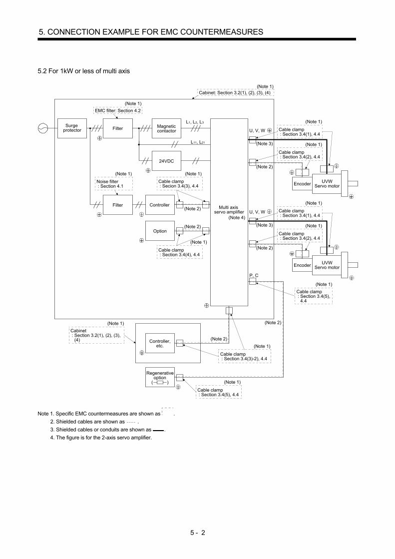
5.2 For 1kW or less of multi axis
Surgeprotector Filter Magnetic
contactor
24VDC
Option
Controller,etc.
ControllerFilter
Regenerativeoption
( )
Cable clamp : Secion 3.4(3), 4.4
Noise filter : Section 4.1
Cable clamp : Section 3.4(4), 4.4
(Note 1) (Note 1)
(Note 2)
(Note 1)
Cabinet : Section 3.2(1), (2), (3), (4)
Cable clamp : Section 3.4(5), 4.4
(Note 1)
Cable clamp : Section 3.4(3)-2), 4.4
(Note 1)
(Note 1)
(Note 2)
EMC filter: Section 4.2
(Note 1)
Cabinet: Section 3.2(1), (2), (3), (4)(Note 1)
(Note 2)
(Note 2)
L1, L2, L3
L11, L21
P, C
Cable clamp : Section 3.4(5), 4.4
(Note 1)
Encoder
Cable clamp : Section 3.4(2), 4.4
(Note 1)
Cable clamp : Section 3.4(1), 4.4
(Note 1)
U, V, W
(Note 2)
(Note 3)
Encoder
Cable clamp : Section 3.4(2), 4.4
(Note 1)
Cable clamp : Section 3.4(1), 4.4
(Note 1)
U, V, W
(Note 2)
(Note 3)
Multi axisservo amplifier
(Note 4)
UVWServo motor
UVWServo motor
Note 1. Specific EMC countermeasures are shown as .
2. Shielded cables are shown as .
3. Shielded cables or conduits are shown as .
4. The figure is for the 2-axis servo amplifier.

5 - 3
5. CONNECTION EXAMPLE FOR EMC COUNTERMEASURES
5.3 For 30kW or more
POINT
The production of the MR-J2-Super series was discontinued in August 2015.
Surgeprotector
Controller,etc.
Encoder
Cabinet : Section 3.2(1), (2), (3), (4)
Cable clamp: Section 3.4(2), 4.4
(Note 1)
Cable clamp : Section 3.4(3)-2), 4.4
(Note 1)
(Note 1)
(Note 2)
(Note 2) (Note 3)
Cable clamp : Section 3.4(1), 4.4
(Note 1)
Cable clamp : Section 3.4(2), 4.4
(Note 1)
Cable clamp : Section 3.4(4), 4.4
(Note 1)
Cable clamp : Section 3.4(3), 4.4
(Note 1) U, V, W
Converter unitMR-CR55K(4)
MR-J3-CR55K(4)MR-HP30KA
MR-HP55KA4
Cable clamp : Section 3.4(1), 4.4
(Note 1)
Cable clamp : Section 3.4(5), 4.4
(Note 1)
Regenerativeoption
( )
Cabinet: Section 3.2(1), (2), (3), (4)
(Note 1)
Filter
24VDC
Option
ControllerFilter
Noise filter : Section 4.1
(Note 1)
(Note 2)
(Note 2)
EMC filter: Section 4.2
(Note 1)
L1, L2, L3
L11, L21
P2, C
L , L (Note 4)
L , L (Note 5)
(Note 2)
(Note 6) Protectioncoordinationcable
24VDC
L11, L21
(Note 2)
(Note 6)
(Note 7)Magneticcontactor
Drive unitMR-J4-DU (4)MR-J3-DU (4)
Servo amplifierMR-J2S- (4)
UVWServo motor

5 - 4
5. CONNECTION EXAMPLE FOR EMC COUNTERMEASURES
Note 1. Specific EMC countermeasures are shown as .
2. Shielded cables are shown as .
3. Shielded cables or conduits are shown as .
4. The abbreviations of the terminals are P and N for MR-HP30KA or MR-HP55KA4.
5. The abbreviations of the terminals are P and N for MR-J2S- (4).
6. Connect the converter unit and drive unit with the provided bus bar.
7. The abbreviation of the terminal is P for MR-HP30KA or MR-HP55KA4.

6 - 1
6. SUPPLEMENT
6. SUPPLEMENT
6.1 Reasons why the shield is grounded on both the cabinet side and the servo motor chassis side
As for a countermeasure against radiated emissions from inverters or servo amplifiers, multiple point grounding, in which grounding is performed at the cabinet exit and both ends of the cable between the servo amplifier and the servo motor, tends to decrease unnecessary noise. 6.1.1 Grounding the shield at the servo amplifier side only
The following figure shows only wiring of the servo motor power cable. Use a shielded wire for the detector cable as well as the power cable. Figure 6.2 shows one of measurement result examples. It does not guarantee the effect of the countermeasure.
Cabinet
To servoamplifier
When a shielded wire is used
Shielded cableServo motor
Servo motor
Motor
Shield
ConnectorConnect the shield part or earthwire coming out outside thecabinet with the earth terminalof the connector at the servomotor side.
Grounding
10 cm or less
MUVW
Fig. 6.1 When the cable between the servo amplifier and servo motor is grounded on the servo amplifier side only
LIMIT: IEC/EN 61800-3 (10 m)
[dBuV/m]100
100 200 300Frequency
×: Ver. (QP)○: Hor. (QP)
HORIZONTAL/VERTICAL
90
80
70
70
60
50
50
40
30
30
20
10
0
Fig. 6.2 Radiated emissions of when the cable between the servo amplifier and servo motor is grounded on the servo amplifier side

6 - 2
6. SUPPLEMENT
6.1.2 Grounding the shield at both ends of the cable
The following figure shows only wiring of the servo motor power cable. Use a shielded wire for the detector cable as well as the power cable. Figure 6.4 shows one of measurement result examples. It does not guarantee the effect of the countermeasure.
Cabinet
To servoamplifier
When a shielded wire is used
Shielded cableServo motor
ConnectorAs close aspossible
10 cmor less
Grounding with the P or U clip
Fig. 6.3 When both ends of the cable between the servo amplifier and servo motor are grounded
LIMIT: IEC/EN 61800-3 (10 m)
[dBuV/m]100
100 200 300Frequency
×: Ver. (QP)○: Hor. (QP)
HORIZONTAL/VERTICAL
90
80
70
70
60
50
50
40
30
30
20
10
0
Fig. 6.4 Radiated emissions of when both ends of the cable between the servo amplifier and servo motor are grounded

6 - 3
6. SUPPLEMENT
6.2 Reasons why the grounding position in the cabinet is specified to be 10 cm or less from the cabinet exit
Various devices are installed inside the cabinet. The devices radiate or transmit significant unnecessary noise. The generated noise may not be held inside the cabinet depending on a cable wiring method. When unnecessary noise is superimposed in the cable, grounding the cable near the cabinet exit should prevent the noise from flowing outside the cabinet. Thus, grounding within 10 cm from the cabinet exit is recommended.
Cabinet
To servoamplifier
Shielded cable
10 cm or less
DeviceNoise
6.3 Reasons why the shield must be grounded with the P clip or U clip
POINT If removing the insulator of a shield causes electrical shock or injuries and threatens the machinery safety, additional protective covers or enclosures may be required.
The surface of a shielded cable is covered with metallic foil or braid (braided wire). High-frequency noise is passed through the shield and unnecessary noise is released outside to the ground, lowering the radiated emissions level. As to grounding the shielded cable, grounding with the P clip or U clip lowers impedance to the ground and allows noise current to flow more smoothly than soldering the wire to the shield or holding the shield cables and extending the length. Thus, grounding with the P clip or U clip is recommended.
Example of groundingwith the P clip
Example of groundingwith the U clip
Example of groundingwith wire soldering
solder

6 - 4
6. SUPPLEMENT
6.4 Connecting multiple servo amplifiers to one EMC filter (1: n connection)
Confirm the EMC standard compliance of the entire machine or equipment on customer side. 6.4.1 Selection method
Molded-casecircuit
breaker
Powersupply
Molded-casecircuit
breaker
MagneticcontactorEMC filter
Servo amplifier(First)
Main circuitpower supply
Control circuitpower supply
Servo motor powercable length
Molded-casecircuit
breaker
Magneticcontactor
Servo amplifier(Second)
Main circuitpower supply
Control circuitpower supply
Servo motor powercable length
Molded-casecircuit
breaker
Magneticcontactor
Servo amplifier(nth)
Main circuitpower supply
Control circuitpower supply
Servo motor powercable length
Servomotor
Servomotor
Servomotor
Fig. 6.5 Connecting multiple servo amplifiers to one EMC filter
When multiple servo amplifiers are connected to one EMC filter with the total length of servo motor power cables too long, the magnetized parts of the EMC filter become magnetically saturated and the noise attenuation properties may be lower than expected. To gain the desired noise attenuation properties with every servo amplifier, select the EMC filter that satisfies the following formulas (6.1 to 6.3) and conditions in Table 6.1. EMC filter rated input voltage [V] ≥ Servo amplifier rated input voltage [V] ············································ (6.1) EMC filter rated input current [A] ≥ Total rated input current of each servo amplifier [A] ··························· (6.2) Total length of servo motor power cables supported by the EMC filter [m] ≥
Total length of servo motor power cables [m] ··································· (6.3)
Table 6.1 EMC filter selection Total length of servo
motor power cable [m] EMC filter
(Soshin Electric)
Rated input current [A] Rated input voltage [V] Leakage current [mA] 100 or less HF3030C-SZL 30 500 7 200 or less HF3060C-SZL 60 500 7 250 or less HF3100C-SZL 100 500 7 250 or less HF3150C-SZL 150 500 7
6 - 5
6. SUPPLEMENT
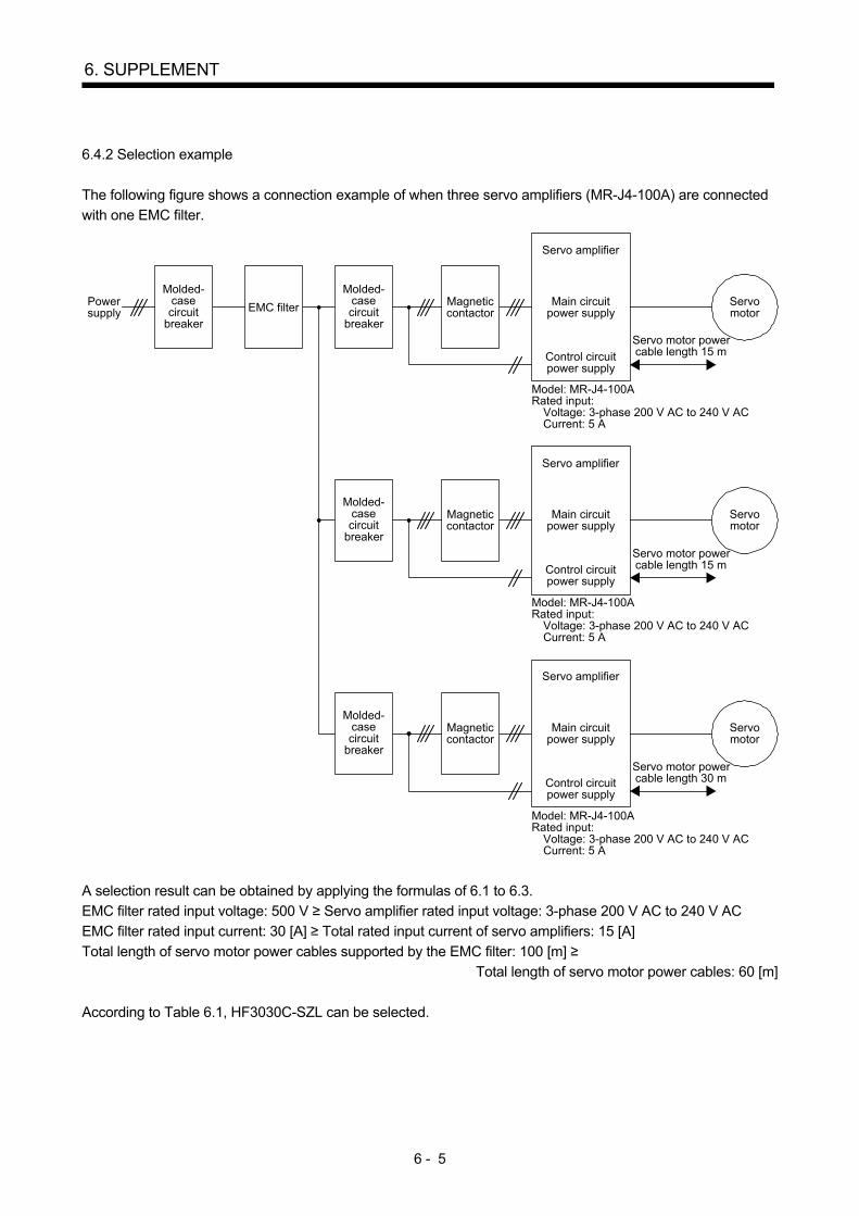
6.4.2 Selection example
The following figure shows a connection example of when three servo amplifiers (MR-J4-100A) are connected with one EMC filter.
Servo motor powercable length 15 m
Servo motor powercable length 30 m
Molded-casecircuit
breaker
Powersupply
Molded-casecircuit
breaker
MagneticcontactorEMC filter
Servo amplifier
Main circuitpower supply
Control circuitpower supply
Model: MR-J4-100ARated input:
Voltage: 3-phase 200 V AC to 240 V ACCurrent: 5 A
Servo motor powercable length 15 m
Molded-casecircuit
breaker
Magneticcontactor
Servo amplifier
Main circuitpower supply
Control circuitpower supply
Model: MR-J4-100ARated input:
Voltage: 3-phase 200 V AC to 240 V ACCurrent: 5 A
Molded-casecircuit
breaker
Magneticcontactor
Servo amplifier
Main circuitpower supply
Control circuitpower supply
Model: MR-J4-100ARated input:
Voltage: 3-phase 200 V AC to 240 V ACCurrent: 5 A
Servomotor
Servomotor
Servomotor
A selection result can be obtained by applying the formulas of 6.1 to 6.3. EMC filter rated input voltage: 500 V ≥ Servo amplifier rated input voltage: 3-phase 200 V AC to 240 V AC EMC filter rated input current: 30 [A] ≥ Total rated input current of servo amplifiers: 15 [A] Total length of servo motor power cables supported by the EMC filter: 100 [m] ≥
Total length of servo motor power cables: 60 [m] According to Table 6.1, HF3030C-SZL can be selected.

6 - 6
6. SUPPLEMENT
MEMO

REVISIONS
*The manual number is given on the bottom left of the back cover. Print Data *Manual Number Revision Apr. 1996 IB(NA)67310-* First edition Nov. 1997 IB(NA)67310-A Chapter 2
Chapter 5 Chapter 6
Table revisions Addition Addition
Nov. 2008 IB(NA)67310-B All pages change Jul. 2009 IB(NA)67310-C Chapter 2
Section 4.2 Section 4.2 (2)(b) Section 5.1
Change of table Part added Part changed Note 4 and 5 added
Jan. 2012 IB(NA)67310-D Chapter 1 Chapter 3 Section 3.1 Section 3.2 Section 3.3 Section 3.4 Section 4.1 Section 4.2 Section 4.3 Section 4.5 Section 4.6 Section 5.1 Section 5.2 Section 5.3
All pages change CAUTION added Part changed Part changed Part changed Part changed Part changed Part added, part changed Part changed Part changed Added Title changed “For 22kW or less” “For 22kW or less of 1-axis” Part change of diagram Added as “For 1kW or less of multi axis” Changes to section 5.3 to section 5.2 of the C version Part change of diagram
Feb. 2013 IB(NA)67310-E Section 4.2 Section 4.2 (1)(a) Section 4.2 (1)(f) Section 4.2 (2)(c) Section 4.6
POINT is added Part added Deleted Deleted POINT is added
Mar. 2014 IB(NA)67310-F 100V class MR-J4 series servo amplifiers are added. Section 4.2 (1)(a)
Section 4.3 MR-J4-10 1 to MR-J4-40 1 are added. E04SRM563218 is added.
Oct. 2014 IB(NA)67310-G MR-J4-DU is added. Section 4.2 (2)(a) Section 5.3
MR-J4-DU30K to MR-J4-DU55K are added. MR-CR55K and MR-J4-DU are added.
Dec. 2015 IB(NA)67310-H Chapter 6 is added. Section 3.1 Section 3.3 Section 3.3 (1) Section 3.4 (1) Section 3.4 (3) Section 4.2 Section 4.6 Chapter 6
POINT is added. Partially changed. POINT is added. Partially changed. Partially added. POINT is added. Partially changed. Partially added. POINT is added. Partially added. POINT is added. Partially added. Newly added.
Jul. 2019 IB(NA)67310ENG-J Section 4.2 (1)(a) Section 4.2 (3) Section 4.6 (a) Section 6.4.1
Part added Added Part added Part changed
This manual confers no industrial property rights or any rights of any other kind, nor does it confer any patent licenses. Mitsubishi Electric Corporation cannot be held responsible for any problems involving industrial property rights which may occur as a result of using the contents noted in this manual.
© 1996 MITSUBISHI ELECTRIC CORPORATION

MELSERVO is a trademark or registered trademark of Mitsubishi Electric Corporation in Japan and/or other countries. All other product names and company names are trademarks or registered trademarks of their respective companies.
IB(NA)67310ENG-J

IB(NA)67310ENG-J (1907) MEE Printed in Japan Specifications are subject to change without notice.
MODEL
MODELCODE 1CW950
EMC INSTRUCTION GUIDELINES
HEAD OFFICE : TOKYO BLDG MARUNOUCHI TOKYO 100-8310