Embed Size (px)
Citation preview

Guidance on the design, construction and testing
of standard rail tank cars
for the transport of chemicals in bulk
Issue 2 May 2016

Page 2/15
INTRODUCTION
This document provides guidance on the design and construction of Rail Tank Cars (RTC’s) and
associated equipment commonly used for the transport in bulk of chemicals.
This document does NOT address the transport of solids or of products with specific requirements e.g.
ethylene oxide, chlorine, ammonia, etc.
The design and construction of RTC’s must, as a minimum, be in compliance with the international
regulations concerning the Carriage of Dangerous Goods by Rail (RID) (see
http://www.otif.org/en/dangerous-goods.html) and with the European Directive 2010/35 on
Transportable Pressure Equipment and other domestic regulations where applicable.
This guidance contains recommendations on top of what is already legally required.
The document is split into 2 columns:
A. Liquids (with a focus on chemicals i.e. non-oil products)
B. Gases (limited to liquefied flammable gases e.g. LPG, propane, butane, butadiene, propylene,
etc. but excluding gases that have specific requirements such as ethylene oxide, chlorine,
ammonia, etc.)
Text that is common to both liquids and gases has been shading in blue.
New text with regard to the previous version is in blue.
This document replaces the previous version of the Cefic Guidelines issued in 2003.
Disclaimer
This document is intended for information only and sets out guidance for the design, construction and testing of
standard rail tank cars for the transport of chemicals in bulk. The information contained in this guidance is
provided in good faith and, while it is accurate as far as the authors are aware, no representations or warranties
are made with regard to its completeness. It is not intended to be a comprehensive guide to all the detailed
aspects of rail transport equipment. No responsibility will be assumed by Cefic in relation to the information
contained in this guidance.

Page 3/15
A. LIQUIDS
B. GASES (liquefied flammable)
CONTENTS
1. Tank design and construction
2. Equipment
2.1 Manhole/manlid
2.2 Pressure/vacuum relief
2.3 Earthing
2.4 Bottom discharge
2.5 Top discharge
2.6 Thermometers/manometers
2.7 Controlled ventilation valves (Auto
vent system)
3. Walkways/platforms
4. Heating/insulation
5. Underframe
6. External painting/cladding
7. Placarding and marking
8. End protection
9. Testing, inspection and certification
10. Information/data to be submitted to the
lessee (consignor) prior to putting into use
RTC’s
CONTENTS
1. Tank design and construction
2. Equipment
2.1. Manhole/manlid
2.2. Pressure relief
2.3. Earthing
2.4. Bottom discharge
2.5. (Not applicable)
2.6. Thermometers/manometers
2.7. (Not applicable)
3. (Not applicable)
4. Sunshield
5. Underframe
6. External painting
7. Placarding and marking
8. End protection
9. Testing, inspection and certification
10. Information/data to be submitted to the
lessee (consignor) prior to putting into use
RTC’s

Page 4/15
A. LIQUIDS
B. GASES (liquefied flammable)
CONTENT
1. TANK DESIGN AND CONSTRUCTION
See RID requirements in RID 6.8.2.1
Materials of tank construction, including coatings,
valves, fittings, gaskets etc. shall be suitable for the
specified products.
For the shells of RTC's, which are intended for
carrying different products, suitable stainless steel is
recommended because of its resistance to a wide
variety of chemicals.
Compared with carbon steel, stainless steel might,
in some cases, also have a positive influence on the
product quality (e.g. colour) and leak-proofness of
the bottom outlet/valve system of the RTC (no rust
in seats of valves).
The materials of shells (or protective linings),
including all other components, which are in contact
with the product, shall not contain substances liable
to react dangerously with the product, or form
dangerous compounds or degrade the material
properties or quality of the carried products.
New or treated stainless steel tanks must be properly
pickled and passivated.
For new tanks, all load bearing attachments shall
have backing plates of a material compatible with
the tank shell, thick enough to distribute incoming
forces to an uncritical limit. Backing plates shall be
fully welded to the shell and shall have all corners
well rounded. Also a small boring is recommended
for stress release.
The tank must be designed for a calculation pressure
as required by RID (see RID 6.8.2.1.14).
It is recommended to have a design pressure of not
less than 4 bar gauge.
Atmospheric (vented) tanks even if allowed by
national and international regulations, are not
recommended.
Vacuum relief valves shall not be fitted.
Hermetically closed shells without vacuum relief
valves shall be designed to withstand a minimum
underpressure of 0.4 bar
1. TANK DESIGN AND CONSTRUCTION
See RID requirements in RID 6.8.2.1 and 6.8.3.1
Materials of tank construction, including coatings,
valves, fittings, gaskets etc. shall be suitable for the
specified products.
The materials of shells (or protective linings),
including all other components, which are in contact
with the product, shall not contain substances liable
to react dangerously with the product, or form
dangerous compounds or degrade the material
properties or quality of the carried products.
For new tanks, all load bearing attachments shall
have backing plates of a material compatible with
the tank shell, thick enough to distribute incoming
forces to an uncritical limit. Backing plates shall be
fully welded to the shell and shall have all corners
well rounded. Also a small boring is recommended
for stress release.
The tank must be designed for a calculation pressure
as required by RID (see RID 4.3.3.2.5).
Measures should be taken (see RID 6.8.2.1.7.) to
protect the shells against the risk of deformation as a
result of a negative internal pressure (vacuum).It is
highly recommended that the tanks are designed to
withstand an underpressure of 1bar.
Page 5/15
A. LIQUIDS
B. GASES (liquefied flammable)
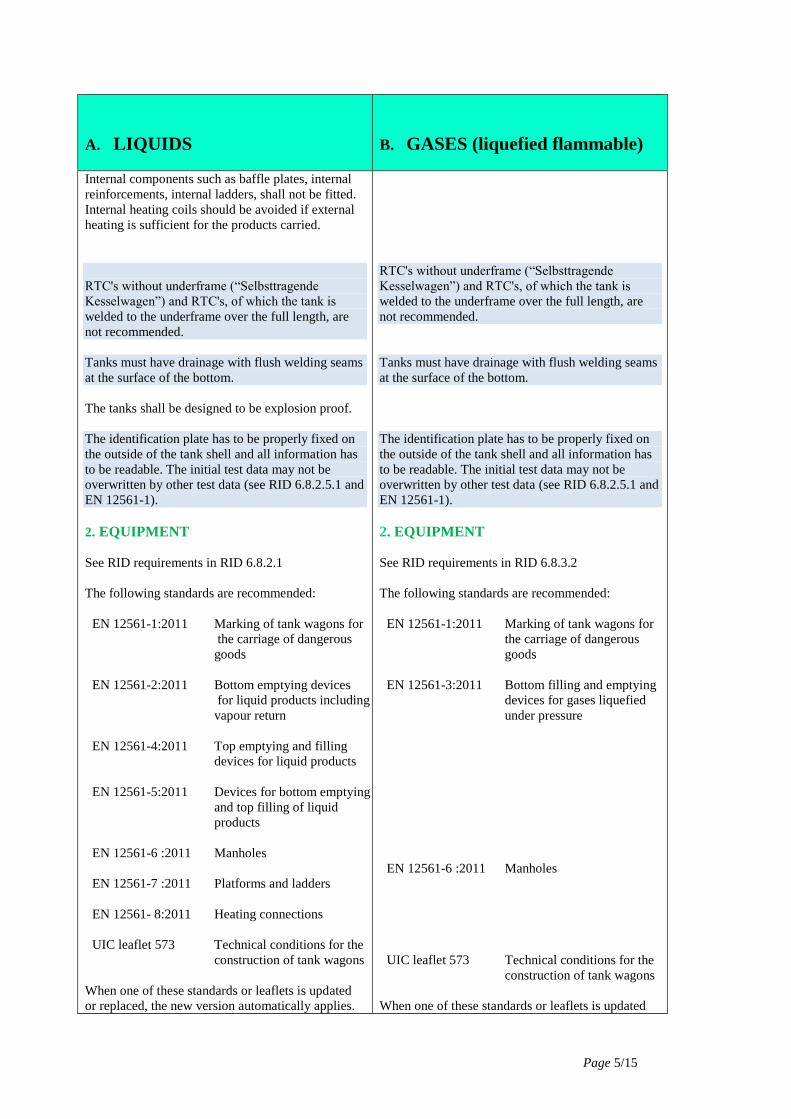
Internal components such as baffle plates, internal
reinforcements, internal ladders, shall not be fitted.
Internal heating coils should be avoided if external
heating is sufficient for the products carried.
RTC's without underframe (“Selbsttragende
Kesselwagen”) and RTC's, of which the tank is
welded to the underframe over the full length, are
not recommended.
Tanks must have drainage with flush welding seams
at the surface of the bottom.
The tanks shall be designed to be explosion proof.
The identification plate has to be properly fixed on
the outside of the tank shell and all information has
to be readable. The initial test data may not be
overwritten by other test data (see RID 6.8.2.5.1 and
EN 12561-1).
2. EQUIPMENT
See RID requirements in RID 6.8.2.1
The following standards are recommended:
EN 12561-1:2011 Marking of tank wagons for
the carriage of dangerous
goods
EN 12561-2:2011
Bottom emptying devices
for liquid products including
vapour return
EN 12561-4:2011 Top emptying and filling
devices for liquid products
EN 12561-5:2011 Devices for bottom emptying
and top filling of liquid
products
EN 12561-6 :2011 Manholes
EN 12561-7 :2011 Platforms and ladders
EN 12561- 8:2011 Heating connections
UIC leaflet 573 Technical conditions for the
construction of tank wagons
When one of these standards or leaflets is updated
or replaced, the new version automatically applies.
RTC's without underframe (“Selbsttragende
Kesselwagen”) and RTC's, of which the tank is
welded to the underframe over the full length, are
not recommended.
Tanks must have drainage with flush welding seams
at the surface of the bottom.
The identification plate has to be properly fixed on
the outside of the tank shell and all information has
to be readable. The initial test data may not be
overwritten by other test data (see RID 6.8.2.5.1 and
EN 12561-1).
2. EQUIPMENT
See RID requirements in RID 6.8.3.2
The following standards are recommended:
EN 12561-1:2011 Marking of tank wagons for
the carriage of dangerous
goods
EN 12561-3:2011 Bottom filling and emptying
devices for gases liquefied
under pressure
EN 12561-6 :2011
Manholes
UIC leaflet 573
Technical conditions for the
construction of tank wagons
When one of these standards or leaflets is updated

Page 6/15
A. LIQUIDS
B. GASES (liquefied flammable)
2.1 Manhole/manlid
There are no specific requirements in RID.
Minimum diameter of the manhole must be 500
mm.
Manlids with swing bolts and butterfly nuts have to
comply with standard EN 12561-6:2011. For
RTC’s, not loaded via the manhole, a closure with
nuts is recommended.
The closing mechanism of the manlid shall be
designed in such a way that internal pressure in the
RTC can be released safely before the lid can be
fully opened.
The manlid must be secured properly when opened
to less than 120 degrees. No obstacles shall prevent
proper closure of the manlid.
The manlid shall be fitted with a joint ring, which
must be compatible with the product being carried.
The manlid shall be gas tight, complying with RID
6.8.2.4.3.
Fittings or other pieces of equipment on hinged
manlid covers are not acceptable.
Hinged manlids must be sealable.
2.2 Pressure/vacuum relief
See RID requirements in RID 6.8.2.2 and 6.8.2.2.3
Pressure/vacuum relief valves shall NOT be fitted if
not required.
2.3 Earthing
See RID requirements in 6.8.2.27 and section 5.5 of
EN 12561-2.
All parts of the tank wagon shall be bonded by
equipotential connections and shall be capable of
being electrically earthed.
Earthing lugs must be available on both sides of the
RTC, next to the outlet nozzle.
In order to ensure proper bonding with the RTC, the
earthing lug shall consist of a stainless steel plate of
at least 40 mm x 80mm x 5mm , which must be
or replaced, the new version automatically applies.
2.1 Manhole/manlid
There are no specific requirements in RID.
Minimum diameter of the manhole must be 500
mm.
The manlid shall be fitted with a joint ring, which
must be compatible with the product being carried.
The manlid shall be gas tight, complying with RID
6.8.2.4.3.
2.2 Pressure relief
See RID requirements in RID 6.8.3.2.9
Pressure relief valves shall NOT be fitted if not
required.
2.3 Earthing
See RID requirements in 6.8.2.27 and section 5.6 of
EN 12561-3.
All parts of the tank wagon shall be bonded by
equipotential connections and shall be capable of
being electrically earthed.
Earthing lugs must be available on both sides of the
RTC, next to the outlet nozzle.
In order to ensure proper bonding with the RTC, the
earthing lug shall consist of a stainless steel plate of
at least 40 mm x 80mm x 5mm , which must be

Page 7/15
A. LIQUIDS
B. GASES (liquefied flammable)
welded directly onto equipment that is connected to
the tank e.g. cradle for tee pipe, “Sattelleiste”
(saddle bar) .
The earthing plate may never be painted and must
be properly marked with the international “earthing”
symbol.
For top loading / unloading, an extra earthing close
to the top connections is recommended.
2.4 Bottom discharge
2.4.1 Bottom valves and operating mechanism
See RID requirements in RID 6.8.2.2
The tank shall be fitted with discharge pipework in
the form of an outlet tee piece. The arm of the tee
shall be directed to each side of the RTC and shall
have a horizontal position.
Each bottom-filling or bottom-discharge opening
shall be equipped with at least three mutually
independent closures, mounted in series,
comprising:
- An internal bottom-valve, i.e. a stop-valve
mounted inside the shell or in a welded
flange or companion flange;
- An external stop-valve or equivalent device,
one at the end of each pipe;
- A closing device at the end of each pipe, which
may be a screw threaded cap, a blind flange or an
equivalent device.
The internal bottom-valve shall be operable from
below. Its setting – open or closed – shall be
capable of being verified. Internal bottom valve
control devices shall be so designed as to prevent
any unintended opening through impact or
inadvertent act.
The internal bottom valve shall continue to be
effective in the event of damage to the external
control device.
welded directly onto equipment that is connected to
the tank e.g. cradle for tee pipe, “Sattelleiste”
(saddle bar) .
The earthing plate may never be painted and must
be properly marked with the international “earthing”
symbol.
2.4 Bottom discharge
2.4.1 bottom valves and operating mechanism
See RID requirements in RID 6.8.2.2.2 and 6.8.3.2.3
The tank shall be fitted with discharge pipework in
the form of two outlet tee pieces. The arms of the
tee shall be directed to each side of the RTC and
shall have a horizontal position.
Each bottom-filling or bottom-discharge opening
shall be equipped with at least three mutually
independent closures, mounted in series,
comprising:
- An internal bottom-valve, i.e. a stop-valve
mounted inside the shell or in a welded
flange or companion flange;
- An external stop-valve or equivalent device,
one at the end of each pipe;
- A closing device at the end of each pipe, which
may be a screw threaded cap, a blind flange or an
equivalent device.
The internal bottom-valves (for liquid and gas
phase) shall be operable from below. Its setting –
open or closed – shall be capable of being verified.
Internal bottom valve control devices shall be so
designed as to prevent any unintended opening
through impact or inadvertent act.
The internal bottom valves shall continue to be
effective in the event of damage to the external
control device.
Internal bottom valves shall be equipped with an
instant-closing internal safety device which closes
automatically in the event of an unintended
movement of the shell. It shall also be possible to
operate the closing device by remote control (see
RID 6.8.3.2.3).

Page 8/15
A. LIQUIDS
B. GASES (liquefied flammable)
The bottom (DN 80 as a minimum) valve may be of
a mechanical or hydraulic type provided the spring
tension has a value of minimum 200 kg.
A marking, which clearly indicates the operating of
the bottom valve, must be visible near the operating
mechanism.
For RTC’s which may carry different products, the
gaskets of the bottom valve must be made out of
PTFE or equivalent material, which must be
compatible with the products carried. Wagons
equipped with PTFE gaskets only should be marked
with gasket class 1.
2.4.2 Bottom discharge connections
See RID requirements in RID 6.8.2.2.2
The outlet piece shall be fitted at each end with an
outlet (side) valve which may be a globe valve
(“Schrägsitz”), plug valve or a ball valve.
The types of the outlet valves must be the same on
both sides.
The discharge end of the outlet tee piece may
terminate in a 5 ½” Whithworth screw-thread which
is commonly used, and a screw (blank) cap and
chain.
Flanges may also be fitted.
The use of dry disconnect couplings is
recommended. However, dry disconnect couplings
should not be used on tanks with crystallisable or
highly viscous substances and also not on carbon
steel tanks as a second closure.
For bottom loading and unloading systems, dry
disconnect couplings may be used as secondary
closure instead of the outlet valve.
If special couplings are not yet fitted, adequate
spacing must be foreseen to connect these onto the
outlet valves in a later stage. Adaptors of 5 ½
Withworth thread to dry disconnect couplings are
NOT recommended. Dry disconnect couplings
should be fitted to a flange.
The bottom valves (DN 80 for liquid phase and DN
80 or DN 50 for gas phase) may be of a mechanical,
hydraulic type provided the spring tension has a
value of minimum 200 kg.
A label, which clearly indicates the operating
instructions of the bottom valves must be attached
to the tank near the operating mechanism.
2.4.2 Bottom discharge connections
See RID requirements in RID 6.8.2.2.2
The outlets shall be fitted at each end with an outlet
(side) valve which may be a globe valve
(“Schrägsitz”) plug valve or a ball valve. However,
for carbon steel wagons, the use of globe valves is
recommended.
The types of the outlet valves must be the same on
both sides.
Types of connections currently used, and described
below, are:
- screw connections: e.g. WECO type
- flange-type connections
- dry disconnect couplings.
When dry disconnect couplings are used, they
should only be fitted as third closure in downstream
direction of the outlet valve.

Page 9/15
A. LIQUIDS
B. GASES (liquefied flammable)
All screw caps shall be fabricated from stainless
steel or the same material as the tank. Plastic caps
are allowed but not recommended. The screw caps
must be fitted with suitable full-flat-face gaskets.
The coupling device is connected to the connection
pipe of the RTC with a flanged type connection.
The coupling device is connected to the connection
pipe of the RTC with a flanged type connection.
Screw-connections
WECO connection
In this case, the RTC is equipped with “female”
half-joints, generally of 3″ and 2″ diameter for the
liquid and gas phases. The half-joint has an external
thread which can be from the ACME or ISO type,
and includes a gasket made of synthetic material
compatible with the product to be carried. The joint
is closed, during transport, by a threaded cap
blocked by contact with the gasket.
In order to ensure that the coupling has not been
removed for unloading by means of flange
connections, it is recommended to have a means to
seal (e.g. a sealable bolt) the flange of the screw
connections.
Dry disconnect couplings
Dry disconnect couplings may be used, only fitted
as a third closure, for gases coupleable under all
working conditions . If they are used, they should
fulfill EN 13175: LPG equipment and accessories -
Specification and testing for Liquefied Petroleum
Gas (LPG) tank valves and fittings.
are recommended.
Example
of dry
gas
coupling
Page 10/15
A. LIQUIDS
B. GASES (liquefied flammable)
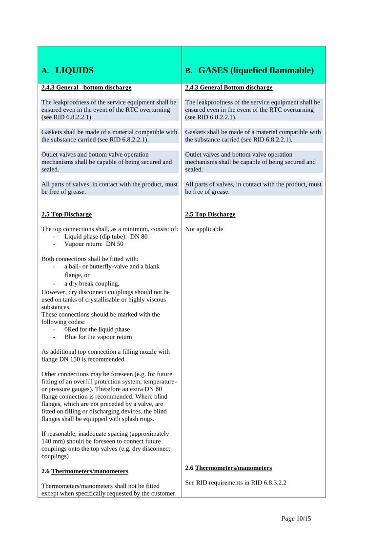
2.4.3 General –bottom discharge
The leakproofness of the service equipment shall be
ensured even in the event of the RTC overturning
(see RID 6.8.2.2.1).
Gaskets shall be made of a material compatible with
the substance carried (see RID 6.8.2.2.1).
Outlet valves and bottom valve operation
mechanisms shall be capable of being secured and
sealed.
All parts of valves, in contact with the product, must
be free of grease.
2.5 Top Discharge
The top connections shall, as a minimum, consist of:
- Liquid phase (dip tube): DN 80
- Vapour return: DN 50
Both connections shall be fitted with:
- a ball- or butterfly-valve and a blank
flange, or
- a dry break coupling.
However, dry disconnect couplings should not be
used on tanks of crystallisable or highly viscous
substances.
These connections should be marked with the
following codes:
- 0Red for the liquid phase
- Blue for the vapour return
As additional top connection a filling nozzle with
flange DN 150 is recommended.
Other connections may be foreseen (e.g. for future
fitting of an overfill protection system, temperature-
or pressure gauges). Therefore an extra DN 80
flange connection is recommended. Where blind
flanges, which are not preceded by a valve, are
fitted on filling or discharging devices, the blind
flanges shall be equipped with splash rings.
If reasonable, inadequate spacing (approximately
140 mm) should be foreseen to connect future
couplings onto the top valves (e.g. dry disconnect
couplings)
2.6 Thermometers/manometers
Thermometers/manometers shall not be fitted
except when specifically requested by the customer.
2.4.3 General Bottom discharge
The leakproofness of the service equipment shall be
ensured even in the event of the RTC overturning
(see RID 6.8.2.2.1).
Gaskets shall be made of a material compatible with
the substance carried (see RID 6.8.2.2.1).
Outlet valves and bottom valve operation
mechanisms shall be capable of being secured and
sealed.
All parts of valves, in contact with the product, must
be free of grease.
2.5 Top Discharge
Not applicable
2.6 Thermometers/manometers
See RID requirements in RID 6.8.3.2.2

Page 11/15
A. LIQUIDS
B. GASES (liquefied flammable)
2.7 Controlled ventilation valves (Auto vent
system)
The RTC may be equipped with an auto vent valve,
which opens simultaneously, or preferably before
the bottom valve is opened. The system may be of a
mechanic and/or hydraulic design.
The auto vent valve (“Zwangsbelüftungsventil”)
shall be connected onto a branch pipe with a
diameter of not less than 50 mm, which extends
from the top to the bottom of the tank. This vapour
return line shall, at the bottom, be connected with a
T-line which is fitted, on both sides of the RTC,
with a blind flange DN 80 or a quick coupling with
blind cap. A vacuum relief valve, fitted directly on
the vapour line, may also be fitted to prevent
implosion during discharge.
For existing RTCs, the use of an external
reinforcement ring, as a vapour line, on the tank is
not recommended . If it is used, a special attention
must be paid to the compatibility between the
material of the line and the vapour. For new RTCs a
separate return line has to be installed.
It is recommended that vapour return lines are fitted
with a device preventing liquids from entering the
vapour return line.
It must be clearly displayed (e.g. with white stripe
or in writing) that an auto vent system is installed
and active.
For RTC’s which are equipped with vapour return
lines, which are not (yet) connected onto an auto
vent valve, a clear indication near the vapour return
Thermometers/manometers shall not be fitted.
2.7 Controlled ventilation valves (Auto vent
system)
Not applicable
Page 12/15
A. LIQUIDS
B. GASES (liquefied flammable)
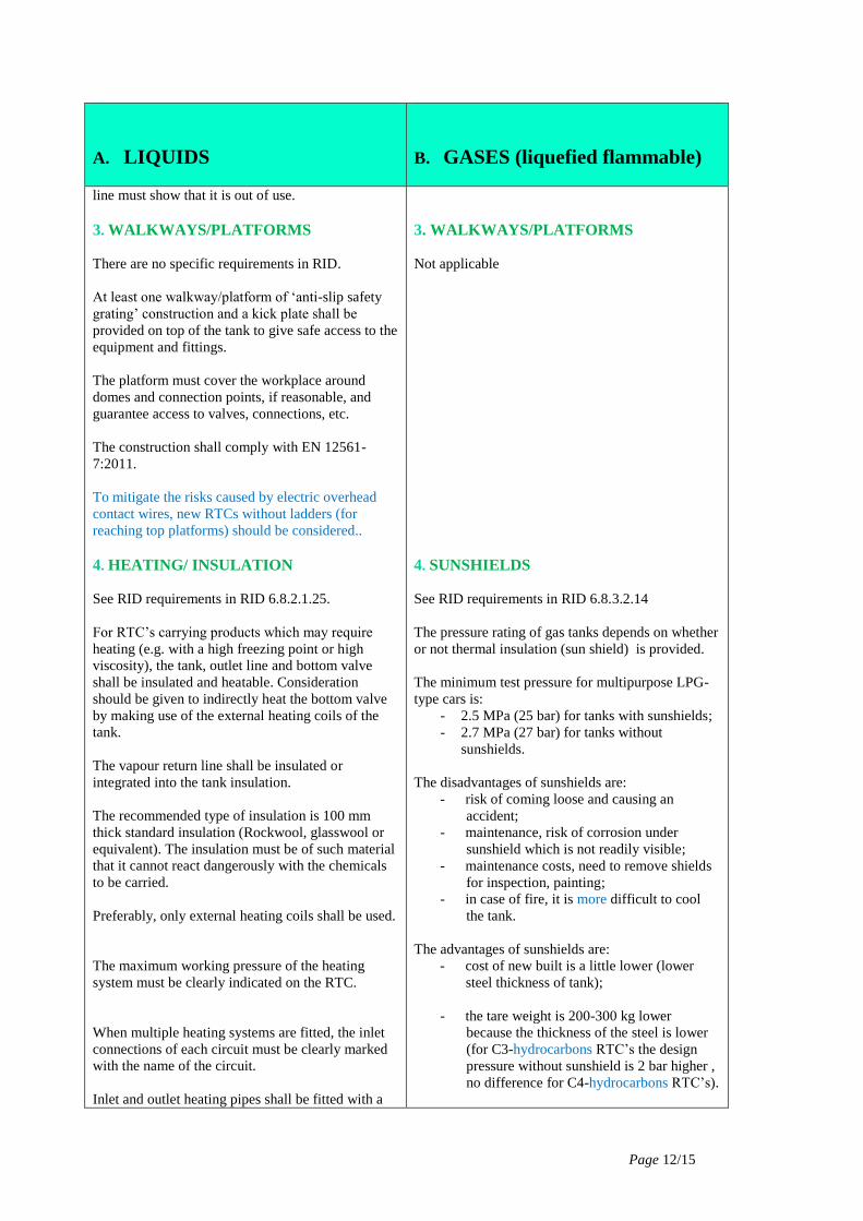
line must show that it is out of use.
NK CARS
3. WALKWAYS/PLATFORMS
There are no specific requirements in RID.
At least one walkway/platform of ‘anti-slip safety
grating’ construction and a kick plate shall be
provided on top of the tank to give safe access to the
equipment and fittings.
The platform must cover the workplace around
domes and connection points, if reasonable, and
guarantee access to valves, connections, etc.
The construction shall comply with EN 12561-
7:2011.
To mitigate the risks caused by electric overhead
contact wires, new RTCs without ladders (for
reaching top platforms) should be considered..
4. HEATING/ INSULATION
See RID requirements in RID 6.8.2.1.25.
For RTC’s carrying products which may require
heating (e.g. with a high freezing point or high
viscosity), the tank, outlet line and bottom valve
shall be insulated and heatable. Consideration
should be given to indirectly heat the bottom valve
by making use of the external heating coils of the
tank.
The vapour return line shall be insulated or
integrated into the tank insulation.
The recommended type of insulation is 100 mm
thick standard insulation (Rockwool, glasswool or
equivalent). The insulation must be of such material
that it cannot react dangerously with the chemicals
to be carried.
Preferably, only external heating coils shall be used.
The maximum working pressure of the heating
system must be clearly indicated on the RTC.
When multiple heating systems are fitted, the inlet
connections of each circuit must be clearly marked
with the name of the circuit.
Inlet and outlet heating pipes shall be fitted with a
3. WALKWAYS/PLATFORMS
Not applicable
4. SUNSHIELDS
See RID requirements in RID 6.8.3.2.14
The pressure rating of gas tanks depends on whether
or not thermal insulation (sun shield) is provided.
The minimum test pressure for multipurpose LPG-
type cars is:
- 2.5 MPa (25 bar) for tanks with sunshields;
- 2.7 MPa (27 bar) for tanks without
sunshields.
The disadvantages of sunshields are:
- risk of coming loose and causing an
accident;
- maintenance, risk of corrosion under
sunshield which is not readily visible;
- maintenance costs, need to remove shields
for inspection, painting;
- in case of fire, it is more difficult to cool
the tank.
The advantages of sunshields are:
- cost of new built is a little lower (lower
steel thickness of tank);
- the tare weight is 200-300 kg lower
because the thickness of the steel is lower
(for C3-hydrocarbons RTC’s the design
pressure without sunshield is 2 bar higher ,
no difference for C4-hydrocarbons RTC’s).

Page 13/15
A. LIQUIDS
B. GASES (liquefied flammable)
closing valve in compliance with EN 12561-8:2011.
5. UNDERFRAME
All RTC’s must have shunting hooks and shall have
lashing devices to be suitable for rail-ferry traffic.
Both wagon ends should have a platform (for
shunters) with handgrip. The platform can be a
crossover platform or a simple step on platform.
Axle load, arc radius and axle distance are limited
for certain customers and must be agreed upon
before delivery.
RL CARS PECIFICATIO
NS
6. EXTERNAL PAINTING/CLADDING
Durable external painting is required for carbon
steel RTC's, which are not insulated.
It is recommended to clad insulated tanks with
stainless steel cladding, at least around discharge
connections and the area underneath. All joints in
the cladding shall be weather-proofed with a
suitable seal to prevent the ingress of water into the
insulation. Insulated carbon steel tanks shall be
painted under the insulation to avoid corrosion.
Measures must be taken to prevent accumulating
condensation within the insulation. Aluminium
cladding is not acceptable around discharge
connections and the area underneath.
7. PLACARDING AND MARKING
See RID requirements in RID 6.8.2.5.2.
For the placards (large danger labels) mounting
plates are recommended. For the orange-coloured
plate marking steel frames to hold the plates shall be
provided at both sides of the RTC. It is
recommended using steel orange-coloured plates
with figures which remain legible after 15 minutes
engulfment in fire.
For product dedicated RTC’s, the name of the
substance carried or name of a group of substances,
for the carriage of which the tank has been
approved, shall be inscribed on each side of the tank
or on a panel.
For marking on freight wagons see EN 15877-
1:2012.
5. UNDERFRAME
All RTC’s must have shunting hooks and shall have
lashing devices to be suitable for rail-ferry traffic.
Both wagon ends should have a platform (for
shunters) with handgrip. The platform can be a
crossover platform or a simple step on platform
Axle load, arc radius and axle distance are limited
for certain customers and must be agreed upon
before delivery.
6. EXTERNAL PAINTING/CLADDING
Durable external painting is required.
7. PLACARDING AND MARKING
See RID requirements in RID 6.8.3.5.
For the placards (large danger labels) mounting
plates are recommended. For the orange-coloured
plate marking steel frames to hold the plates shall be
provided at both sides of the RTC. Steel swing
panels with the orange-coloured plates painted on it
may also be used. It is however recommended to
use steel orange-coloured plates with figures which
remain legible after 15 minutes engulfment in fire.
The name of the substance carried, for the carriage
of which the tank has been approved, shall be
inscribed on each side of the tank or on a panel.
Swing panels shall be lockable and sealable.
For marking on freight wagons see EN 15877-
1:2012.

Page 14/15
A. LIQUIDS
B. GASES (liquefied flammable)
8. END PROTECTION
Buffer override protection
See RID requirements in 6.8.4, in particular special
provisions TE25.
Crash buffers
See RID requirements in 6.8.4 in particular special
provision TE22.
Crash buffers can help to reduce the consequences
in cases of accidents
9. TESTING, INSPECTION AND
CERTIFICATION
See RID requirements in 6.8.2.4
Companies may require more frequent inspections
depending on the nature of the product e.g. risk of
polymerisation.
The RTC owner must submit test certificates to the
lessee.
Prior to putting into service, the lessor of the RTC
shall carry out a technical and cleanliness inspection
of the RTC including a leak proof test.
The required cleanliness shall be defined by means
of a national or international recognised “cleanliness
Key” (e.g. UIP “Reinheitsschlüssel”).
8. END PROTECTION
Buffer override protection
See RID requirements in 6.8.4, in particular special
provision TE25.
Buffer override protection or an alternative head
protection is recommended, if justified and feasible.
Crash buffers
See RID requirements in 6.8.4 in particular special
provision TE22.
Crash buffers can help to reduce the consequences
in cases of accidents
9. TESTING, INSPECTION AND
CERTIFICATION
See RID requirements in 6.8.2.4 and 6.8.3.4
Initial and periodical tests and inspections of the
tank must be carried out in accordance with RID
6.8.2.4 and 6.8.3.4 and EN 12972.
The RTC owner must submit test certificates to the
lessee.
Prior to putting into service, the lessor of the RTC
shall carry out a technical and cleanliness inspection
of the RTC including a leak proof test .
The required cleanliness shall be defined by means
of a national or international recognised “cleanliness
Key” (e.g. UIP “Reinheitsschlüssel”).

Page 15/15
A. LIQUIDS
B. GASES (liquefied flammable)
10. INFORMATION/DATA TO BE
SUBMITTED TO THE LESSEE
(CONSIGNOR) PRIOR TO PUTTING
INTO USE RTC’S
Up-to-date specification sheet including as a
minimum:
- arc radius
- length of RTC
- maximum axle distance
- tare weight
- capacity of the tank
- allowable loading weights per loading
category
- design-, test- and working pressure
- design temperature
- maximum allowable underpressure
- material of tank shell
- working- and test pressure of heating
- type of connections including type of
valves
- auto vent system
- special features
- type of gaskets fitted.
Further information required:
- construction year of the RTC
- last inspection/revision and test date of
tank and underframe
- UIP cleanliness key.
R
AIL TANK NS
10. INFORMATION/DATA TO BE
SUBMITTED TO THE LESSEE
(CONSIGNOR) PRIOR TO PUTTING
INTO USE RTC’S
Up-to-date specification sheet including as a
minimum:
- arc radius
- length of RTC
- maximum axle distance
- tare weight
- capacity of the tank
- allowable loading weights per loading
category
- design- and test-pressure
- design temperature
- maximum allowable underpressure
- material of tank shell
- type of connections including type of
valves
- special features
- type of gaskets fitted.
Further information required:
- construction year of the RTC
- last inspection/revision and test date of tank
and underframe
- UIP cleanliness key.