Embed Size (px)
Citation preview

8/9/2019 Standard Bridge Beams
http://slidepdf.com/reader/full/standard-bridge-beams 1/67
Transfund New Zealand Research Report No. [……..]
NEW STANDARD PRECASTCONCRETE BRIDGE BEAMSStage 1 – Research & IdentifyProposed Standard Beam Shapesand Spans
Alex Gray & Phil Gaby, Beca Carter Hollings & Ferner Ltd
Geoff Brown & Donald Kirkcaldie, Opus International ConsultantsRoss Cato & Paul Sweetman, Precast New Zealand

8/9/2019 Standard Bridge Beams
http://slidepdf.com/reader/full/standard-bridge-beams 2/67
ISBN..................................................................
ISSN ..................................................................
Keywords: standard precast concrete bridge beams New Zealand.
© 2003, Transfund New ZealandPO Box 2331, Lambton Quay, Wellington, New ZealandTelephone 64-4-473-0220; Facsimile 64-4-499-0733

8/9/2019 Standard Bridge Beams
http://slidepdf.com/reader/full/standard-bridge-beams 3/67
An Important Note for the Reader
The research detailed in this report was commissioned by Transfund New Zealand
Transfund New Zealand is a Crown entity established under the Transit New Zealand Act 1989. Its principal objective is to allocate resources to achieve a safe and efficient roading system. Each year,Transfund New Zealand invests a portion of its funds on research that contributes to this objective.
While this report is believed to be correct at the time of its preparation, Transfund New Zealand, andits employees and agents involved in the preparation and publication, cannot accept any liability for itscontents or for any consequences arising from its use. People using the contents of the documentshould apply, and rely upon, their own skill and judgement. They should not rely on its contents inisolation from other sources of advice and information.
The report is only made available on the basis that all users of it, whether direct or indirect, must takeappropriate legal or other expert advice in relation to their own circumstances. They must rely solelyon their own judgement and seek their own legal or other expert advice in relation to the use of thisreport.
The material contained in this report is the output of research and should not be construed in any way
as policy adopted by Transfund New Zealand but may form the basis of future policy.
8/9/2019 Standard Bridge Beams
http://slidepdf.com/reader/full/standard-bridge-beams 4/67
CONTENTS
Executive summary
Abstract
1 INTRODUCTION .............................................................................................................. 8 2 REVIEW OF CURRENT SITUATION IN NEW ZEALAND ...................................... 9 2.1 Background 92.2 Existing Standard Bridge Beams 92.3 Issues to be Addressed with the Existing Standard Bridge Beams 122.4 Other Beam Sections Currently Used in New Zealand 123 LITERATURE REVIEW OF CURRENT INTERNATIONAL PRACTICE............ 14 3.1 General 143.2 Australia 14
3.2.1 General ................................................................................................... 14
3.2.2 Australian Beam Shapes and Practice .................................................... 143.3 United Kingdom 16
3.3.1 General ................................................................................................... 163.3.2 United Kingdom Beam Shapes and Practice.......................................... 16
3.4 North American Practice 173.4.1 General ................................................................................................... 173.4.2 North American Beam Shapes and Practice........................................... 20
3.5 Summary of Literature Review Findings 214 SURVEY OF NEW ZEALAND PRECAST PRESTRESSED BRIDGE BEAM
MANUFACTURERS ................................................................................................................ 24 4.1 General 24
4.2 Survey Methodology 244.3 Survey Results 244.4 Interpretation of results 25
4.4.1 Span/depth ratios .................................................................................... 255 INDUSTRY CONSULTATION AND PARTICIPATION........................................... 27 5.1 General 275.2 Industry Group 275.3 Industry Consultation Workshops 275.4 Summary of Consultation 286 ANALYSIS OF RESEARCH RESULTS ....................................................................... 29 6.1 General 29
6.2 Preferred Standard Beam Shapes 296.3 Criteria for Selecting New Standard Beam Shapes 296.4 Selection of New Beam Shapes 32
6.4.1 Review of Existing Standard Beam Shapes ........................................... 336.4.2 Review of Other Beam Shapes Currently Used in New Zealand........... 346.4.3 Review of Beam Shapes Currently Used Overseas................................ 346.4.4 Selection of Beam Shapes ...................................................................... 366.4.5 New Standard Beam Shapes Proposed................................................... 37
7 PRELIMINARY DESIGN OF NEW BEAM SHAPES................................................ 40 7.1 General 40
8/9/2019 Standard Bridge Beams
http://slidepdf.com/reader/full/standard-bridge-beams 5/67
7.2 Criteria for a Standard Bridge Superstructure 407.3 Hollow Core Beams 42
7.3.1 General ................................................................................................... 427.3.2 Span Range and Unit Depths.................................................................. 42
7.3.3 Width of Units ........................................................................................ 427.3.4 Void Shape ............................................................................................. 437.3.5 Concrete Strength ................................................................................... 447.3.6 Transverse Design .................................................................................. 447.3.7 Longitudinal Joints Between Units ........................................................ 457.3.8 Maintenance Issues................................................................................. 467.3.9 Summary of Findings ............................................................................. 46
7.4 “I” Beams 477.4.1 General ................................................................................................... 477.4.2 Beam Spacing ......................................................................................... 477.4.3 Beam Shape ............................................................................................ 47
7.4.4 Concrete Strength ................................................................................... 487.4.5 Edge Protection Requirements ............................................................... 487.4.6 Durability................................................................................................ 487.4.7 Summary of Findings ............................................................................. 49
7.5 Super-T Beams 497.5.1 General ................................................................................................... 497.5.2 Span Range for the various depths of unit.............................................. 497.5.3 Flange Width and Beam Spacing ........................................................... 507.5.4 Top slab Depth ....................................................................................... 507.5.5 Concrete Strength ................................................................................... 507.5.6 Prestressing............................................................................................. 507.5.7 Edge Protection ...................................................................................... 517.5.8 Durability................................................................................................ 517.5.9 Maintenance ........................................................................................... 51
7.6 Overall Summary 518 COST ESTIMATES AND ECONOMIC ANALYSIS .................................................. 52 8.1 General 528.2 Cost Estimates for New Beam Shapes 528.3 Economic Assessment of New Beam Shapes 53
8.3.1 Summary of Findings ............................................................................. 539 CONCLUSIONS AND RECOMMENDATIONS ......................................................... 54 9.1 Conclusions 549.2 Recommendations 54
APPENDICES
Appendix 1: International Literature ReviewAppendix 2: Survey Details of New Zealand Precast Prestressed Bridge Beam
Manufacturers
8/9/2019 Standard Bridge Beams
http://slidepdf.com/reader/full/standard-bridge-beams 6/67
6
EXECUTIVE SUMMARY
The objective of Stage 1 of this research project was to research and identify the mostappropriate precast concrete bridge beam shapes that should be adopted as industrystandards for the future.
This research was considered a priority as the standard bridge beam designs currentlyused in New Zealand were adopted as industry standards in the 1970’s. These designsare almost 30 years old and out of date with respect to design codes, constructiontechniques and the higher strength materials now commonly used.
As well as reviewing current New Zealand practice the researchers did a literaturesurvey of standard beam usage in Australia, North America and the United Kingdom.
Also, many precasters of bridge beams in New Zealand contributed data to a survey.From this survey information and statistics were produced to indicate the most popular
beam shapes currently in use.
Extensive consultation of a wide range of industry participants was a crucial part of theresearch process. Workshops were held in three main centres to allow all sectors of theindustry to raise and discuss issues. This included a poll of participants to select a new
beam shape.
From the research above and consultation comments a range of beam selection criteriawere then developed to identify the key criteria that needed to be addressed in anyfuture designs. The most important criteria was the inclusion of the bridgesuperstructure in the standard bridge beam series of drawings. The research teamconcluded that for cost and practicality reasons that a standard bridge superstructureshould be developed to limit the range of spans and cross section widths for the new
bridge beams.
The beam shapes recommended for new detailed designs by the research team are theexisting hollow core deck units for spans up to both 18 and 25 metres and the existing“I” beams for spans up to 32 metres. The new shape proposed is the Super-T beam for
spans up to 30 metres.

8/9/2019 Standard Bridge Beams
http://slidepdf.com/reader/full/standard-bridge-beams 7/67
7
ABSTRACT
The objective of Stage 1 of this research project (carried out from July 2002 to March
2003) was to research and identify the most appropriate precast concrete bridge beamshapes that should be adopted as industry standards for the future.
This research was considered a priority as the standard bridge beam designs currentlyused in New Zealand were adopted as industry standards in the 1970’s. These designsare almost 30 years old and out of date with respect to design codes, constructiontechniques and the higher strength materials now commonly used.
The researchers carried out a literature survey of standard beam usage in Australia, North America and the United Kingdom along with a survey of current New Zealand practice.
Following a survey of bridge beam precasters and three consultation workshops a rangeof key beam selection criteria were developed that needed to be addressed in any futuredesigns.
The researchers recommended that full designs for two existing beam shapes (hollowcore and “I” beam) and one new shape (Super-T) be carried out in the second stage ofthe project.
8/9/2019 Standard Bridge Beams
http://slidepdf.com/reader/full/standard-bridge-beams 8/67
8
1 INTRODUCTION
In the mid 1970’s the Ministry of Works (MOW) designed a range of twin hollow-core,“I” and “U” precast concrete bridge beams and small span bridges which were adoptedas New Zealand industry standards. These standard designs led to cost efficiencies bothin design time and also the use of standard moulds by precasters led to morecompetitive tenders for supply of bridge beams. Probably thousands of these standard
beams were used in bridges all over New Zealand during the next 20 years.
The standard MOW bridge beam designs completed in the 1970’s era are now nearly 30years old and out of date both with respect to design codes and construction techniquesnow commonly used. In particular, changes to durability, width and side protectionrequirements have affected the current beam designs.
This report presents the findings of the research project carried out from July 2002 toMarch 2003 to research and identify the most appropriate precast concrete bridge beamshapes that should be adopted as industry standards for the future.
The steps involved in this research were:
• Formation of an Industry Group to comment on bridge beam options;
• Research current beam usage in NZ and compare with overseas usage (literaturereview);
• Survey NZ Precast Manufacturers
• Develop beam selection criteria;
• Consult with Industry representatives in 3 main centres;• Analyse research results;
• Preliminary design of new beam shapes;
• Cost estimates and economic analysis;
• Derive conclusions and make recommendations.
The research team is made up of bridge designers, precast beam manufacturers and arepresentative of the precast concrete industry. The research team members are:
• Alex Gray – Team leader (Beca)
• Geoff Brown – Deputy team leader and bridge designer (Opus)• Ross Cato – Representative of Precast New Zealand
• Paul Sweetman – Beam manufacturer (Smithbridge)
• Ian Billings – Bridge designer (Beca)
• Phil Gaby – Bridge designer (Beca)
• Don Kirkcaldie – Bridge designer (Opus)
8/9/2019 Standard Bridge Beams
http://slidepdf.com/reader/full/standard-bridge-beams 9/67
9
2 REVIEW OF CURRENT SITUATION IN NEW ZEALAND
2.1 Background
The existing standard bridge beams include a range of different section types to be usedfor different spans of between 6 and 32 metres. Other superstructure elements includingdeck slabs, transverse diaphragms, edge protection details and seismic restraint detailswere also provided to give complete superstructure designs for the various beam types.The designs cover both single lane and two lane bridges, with and without footways,
based on the bridge width standards when last updated during the mid-1990’s.
2.2 Existing Standard Bridge Beams
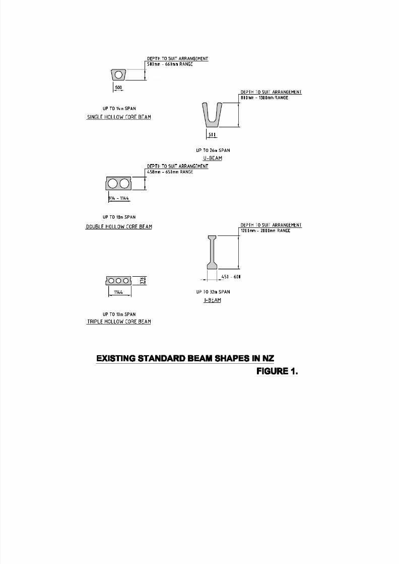
The existing standard bridge designs, which are contained in the Ministry of Works publication “Highway Bridges Standard Plans”, (also known as the “red book”), coverthe following beam shapes and span ranges:
• Precast pre-tensioned single circular hollow core deck units – 8 m to 14 m spans
• Precast pre-tensioned double circular hollow core deck units – 6 m to 18 m spans
• Precast pre-tensioned triple hollow core deck units – 6 m to 10 m spans
• Precast pre-tensioned “I” beams – 12 m to 20 m spans
• Precast combined pre and post-tensioned “I” beams – 18 m, 20 m, 22 m and 24 mspans
• Precast post- tensioned “I” beams – 18 m, 20 m, 24 m, 28 m and 32 m spans• Precast pre-tensioned “U” beams- 16 m, 18 m, 20 m, 22 m, 24 m and 26 m spans
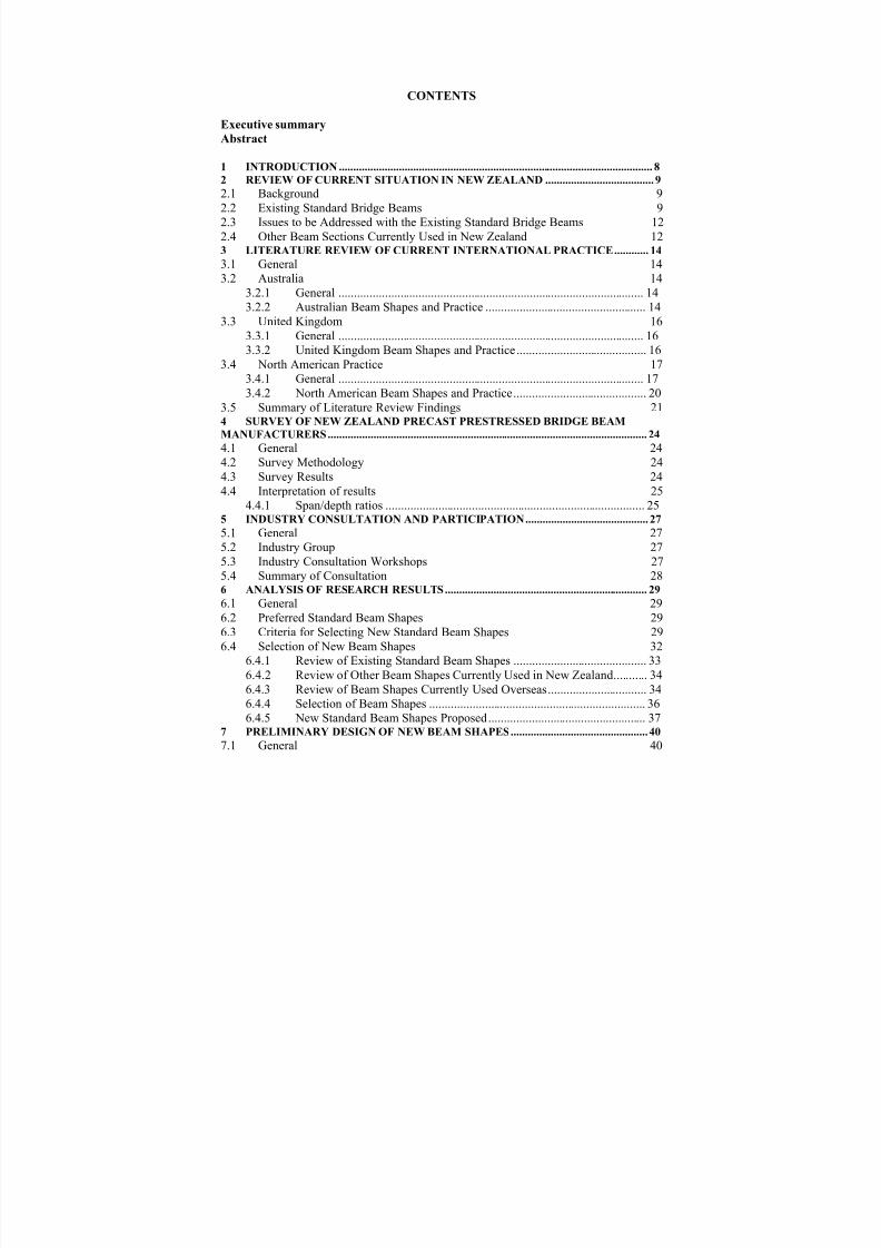
Cross sections of the existing standard beam shapes in New Zealand are shown overleafin Figures 1 and 2.
For each of these beam types full construction drawings are provided in the “red book”including beam and deck geometry, prestressing details, reinforcement details for the
beams, deck slabs and transverse diaphragms, and general details covering joints between beams, seismic restraint connection to both piers and abutments, and edge protection for Bridge Guardrail and New Jersey Barrier systems. The “red book” also
contains details of rural farm bridges, precast concrete piles and seismic linkages.
From the range of standard beams listed above, the single and triple hollow core deckunits are now rarely used and the “U” beams are considered to be uneconomic for manysituations except in some urban projects with limited headroom. Similarly, the longer“I” beam spans are not extensively used. The most popular designs are the doublehollow core deck units in the span range of 12 to 18 metres and “I” beams for spans upto 24 metres. The span range for double hollow core deck units has also been extendedto 22 metres for specific projects.
8/9/2019 Standard Bridge Beams
http://slidepdf.com/reader/full/standard-bridge-beams 10/67

8/9/2019 Standard Bridge Beams
http://slidepdf.com/reader/full/standard-bridge-beams 11/67
OTHER SHAPES USED IN NZ.
FIGURE 2.
8/9/2019 Standard Bridge Beams
http://slidepdf.com/reader/full/standard-bridge-beams 12/67
12
The “red book” replaced the earlier “blue book” following a revision of the beams in1988. The “blue book” was published for general use by the industry whereas the “red
book” was an in-house Ministry of Works publication.
2.3 Issues to be Addressed with the Existing Standard Bridge Beams
The existing designs have a number of issues relating to changes of standards for bridges that have occurred since the designs were last updated. These standards are setout in the Transit New Zealand Bridge Manual, and include:
• Increased durability requirements
• Changes to bridge width requirements
• Enhanced edge protection standards
• Possible changes to bridge design loading (currently undergoing consultation with
industry)• Changes to design criteria eg use of partial prestress now permitted.
These changes to standards have led to the current beam designs becoming out of dateand requiring modification on an individual project basis.
In addition, there are a number of other issues that need to be addressed relating to the performance of the current designs, as identified through their use over recent years.These issues have been identified from feedback within the industry, and include:
•Reflective longitudinal cracking to surfacing on some bridges above longitudinal joints between double hollow core deck units, particularly in longer spans
• Problems during manufacture of voided slabs due to void flotation in wet concrete
• Possible instability of longer span “I” beams during erection due to the narrow topflanges
• Safety concerns in erecting permanent formwork between widely spaced “I” beams
• The economy of the current designs for the longer span ranges (typically >25metres).
Completion of this research project (Stage 2 – Standard Designs) will afford theopportunity to address issues with the current standard bridge designs and, where
practical, propose solutions.
2.4 Other Beam Sections Currently Used in New Zealand
In addition to the standard beam designs originating from the Ministry of Works, anumber of other beam shapes are increasingly being used on a project-by-project basisin New Zealand. These are known to include the following sections:
• Precast hollow core deck units with a single rectangular void for a variety of spansup to 25 metres

8/9/2019 Standard Bridge Beams
http://slidepdf.com/reader/full/standard-bridge-beams 13/67
13
• Precast Super-T beams and Tee-Roff beams (similar to those used in Australia)
We understand the Tee-Roff beam was a variant of the Super-T beam which wasdeveloped for a specific Australian project.
Individual designers and precast beam manufacturers also have their own designs thatare used for specific projects.

8/9/2019 Standard Bridge Beams
http://slidepdf.com/reader/full/standard-bridge-beams 14/67
14
3 LITERATURE REVIEW OF CURRENT INTERNATIONALPRACTICE
3.1 General
For a project of this size, time and budget considerations precluded investigating a largenumber of countries. Instead, we carefully considered similarities between differentcountries and New Zealand and selected the following four countries for a detailedliterature review:
• Australia – due to its proximity to NZ and similar current traffic loadings;
• United Kingdom – due to the wide range of shapes available and new shapesrecently adopted;
• North America – due to several states having used standard precast bridge beamdesign for many years, new beam designs recently developed, and similar trafficloadings.
The literature review was conducted using standard database searches. In additionspecific firms and organisations involved with precast bridge beams were also contactedfor their information and views. (Refer Appendix 1).
3.2 Australia
3.2.1 General
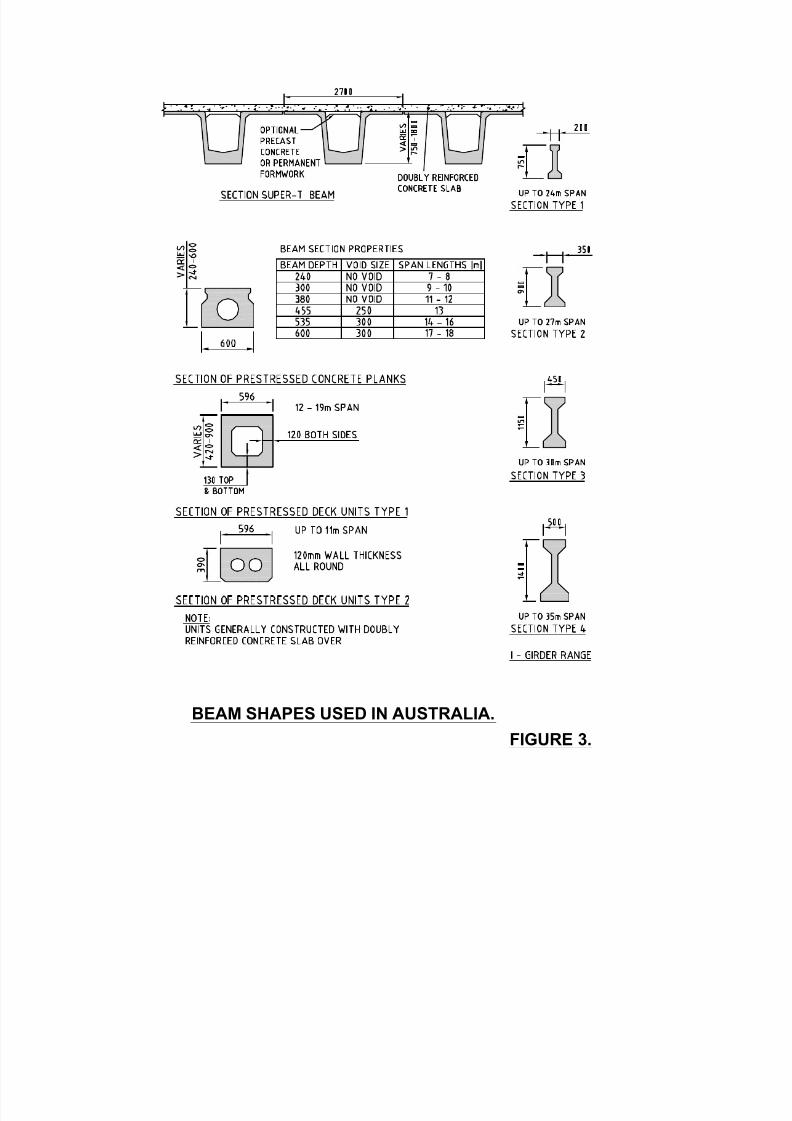
Discussions were held with specialists such as the National Precast ConcreteAssociation of Australia, consultants and clients which showed up to a 17 metre spanthat the trend in this country is to use precast voided planks. In New South Wales(NSW) this is typically constructed with a double reinforced concrete overlay. InQueensland this section is also used in the same span range but usually without anyoverlay, but with a shear key detail between the abutting units and transverse prestress.
For spans from 18 to 35 metres in NSW the Road and Traffic Authority have a range ofSuper-T girders for which standard shapes have been developed with depths ranging
from 1.0 to 1.80 metres. This new shape developed in the late 1980’s and early 1990’shas predominately taken over from the previously used “I” beam (which is nowinfrequently used).
3.2.2 Australian Beam Shapes and Practice
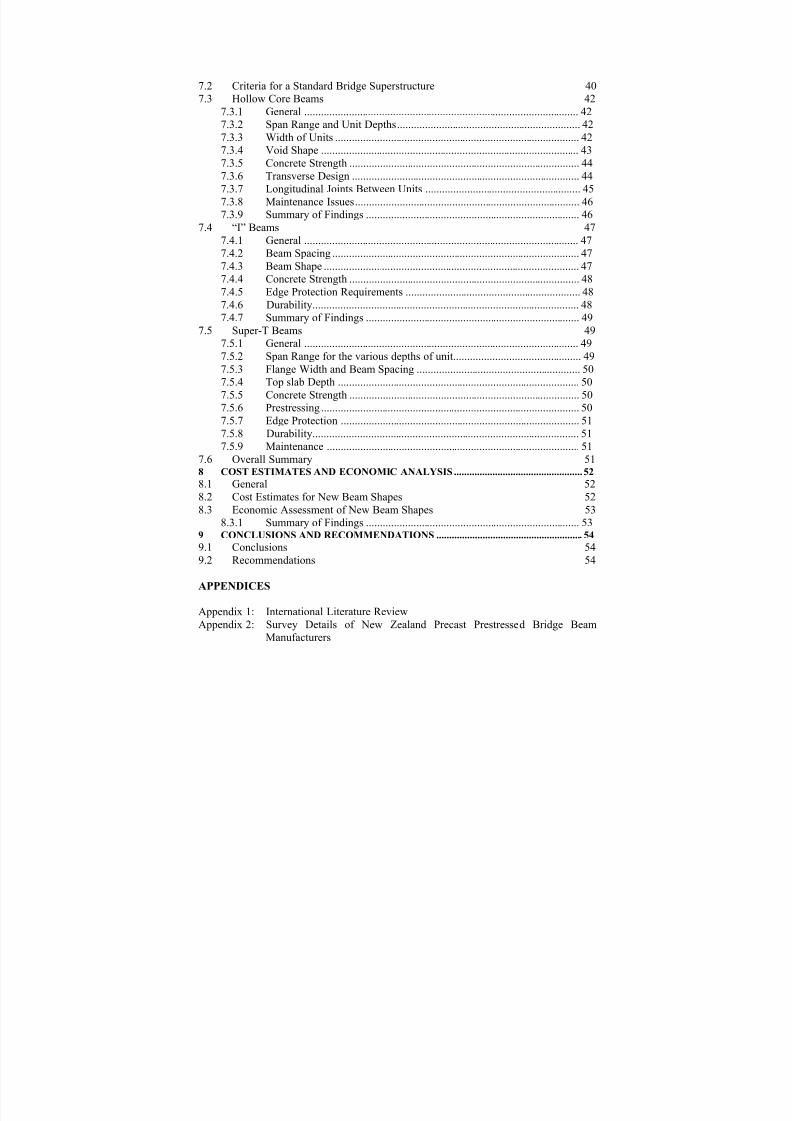
Table 1 and Figure 3 show the range of beam shapes used in Australia.
8/9/2019 Standard Bridge Beams
http://slidepdf.com/reader/full/standard-bridge-beams 15/67
BEAM SHAPES USED IN AUSTRALIA.
FIGURE 3.

8/9/2019 Standard Bridge Beams
http://slidepdf.com/reader/full/standard-bridge-beams 16/67
16
The general trend is to use hollowcore planks up to a 17 metre span followed by voided box beams up to a 27 metre span.
The Super-T section has a theoretical range from 18 to 35 metres but is little used in the
18 to 20 metres range due to the voided box beam being more cost effective.
Longer span Super-T beams spanning up to 48 metres (and weighing up to 200 tonne)have been designed and constructed for individual projects such as the KwinanaFreeway near Perth.
The Super-T has rapidly become the preferred section for most bridge spans in the 22 to35 metres range. Many contractors now have moulds for this shape resulting incompetitive prices for specific contracts.
Table 1 Current Australian Practice
Span Range Precast Section Comments
Spans up to 17 m Standard PSC voided planks(NSW predominantly)
Doubly reinforced concreteoverlay or transverse prestress
Spans up to 27 m Voided box beams (Australiawide)
Doubly reinforced concreteoverlay or transverse prestress
Spans between 18 m – 35 m Super-T & the Tee-Roff beam Reinforced Concrete top slab.Flanges of Super-T and Tee-Roff provide formwork
Spans between 18 m – 35 m ‘I’ girder Infrequently used. Tee-Roffand Super-T taking over
3.3 United Kingdom
3.3.1 General
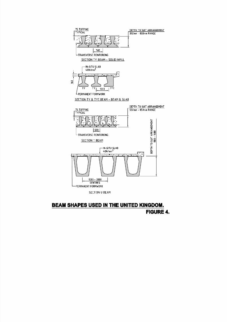
Due to the size of the market in the UK, there is a much larger range of precast beamshapes in use. Also, with many motorway widening projects in progress (to widen
motorways from 4 to 6 lanes) new shapes such as the “SY” beam have been developedto span up to 40 metres.
Concrete strengths in the UK are typically a 50 MPa cube strength. This equates to acylinder strength of approximately 43 MPa.
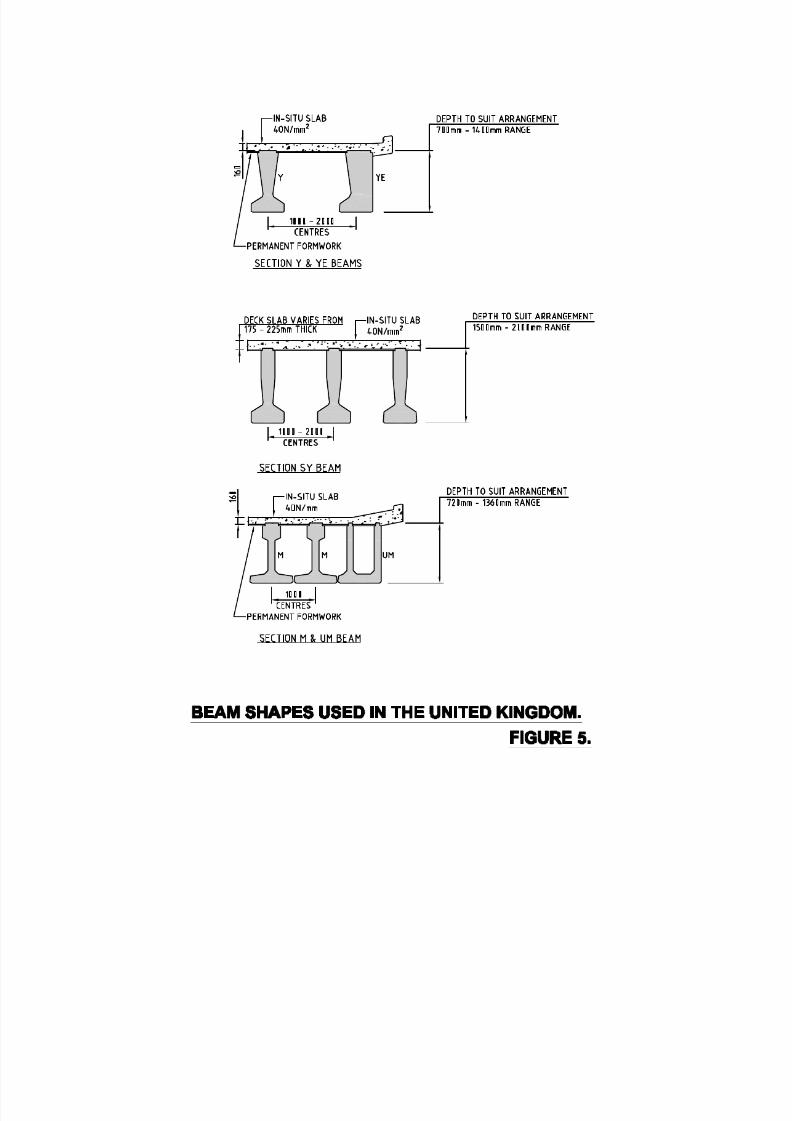
3.3.2 United Kingdom Beam Shapes and Practice
Table 2 and Figure 4 and 5 shows the range of beam shapes in use in the UnitedKingdom.

8/9/2019 Standard Bridge Beams
http://slidepdf.com/reader/full/standard-bridge-beams 17/67
8/9/2019 Standard Bridge Beams
http://slidepdf.com/reader/full/standard-bridge-beams 18/67
8/9/2019 Standard Bridge Beams
http://slidepdf.com/reader/full/standard-bridge-beams 19/67

8/9/2019 Standard Bridge Beams
http://slidepdf.com/reader/full/standard-bridge-beams 20/67
20
Recent development of new shapes for precast bridge beams to replace the AASHTO beams that have been in use for many years was the key finding of the research. Thistrend was seen in many of the state departments of transportation, and confirmed byrecently published technical papers
The development of new shapes has concentrated on “I” beam and box beam shapes andin particular in providing for longer span ranges. These beams still require an insituconcrete deck slab to be provided using temporary or permanent formwork.
The new shapes have improved the efficiency of the beam in terms of material use andease of manufacture. Generally, the new shapes have wider flanges than the earlierASSHTO “I” beams.
Precast plank units with circular voids are still widely used for shorter span bridges asare ribbed or multiple “T” units.
Typically concrete strengths vary between 35 MPa and 45 MPa, but higher concretestrengths have been adopted by some states for new beam designs, with concrete of upto 70 MPa being specified.
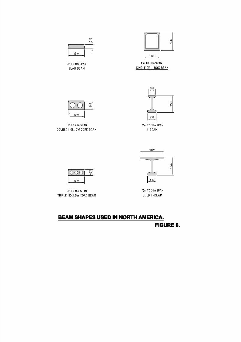
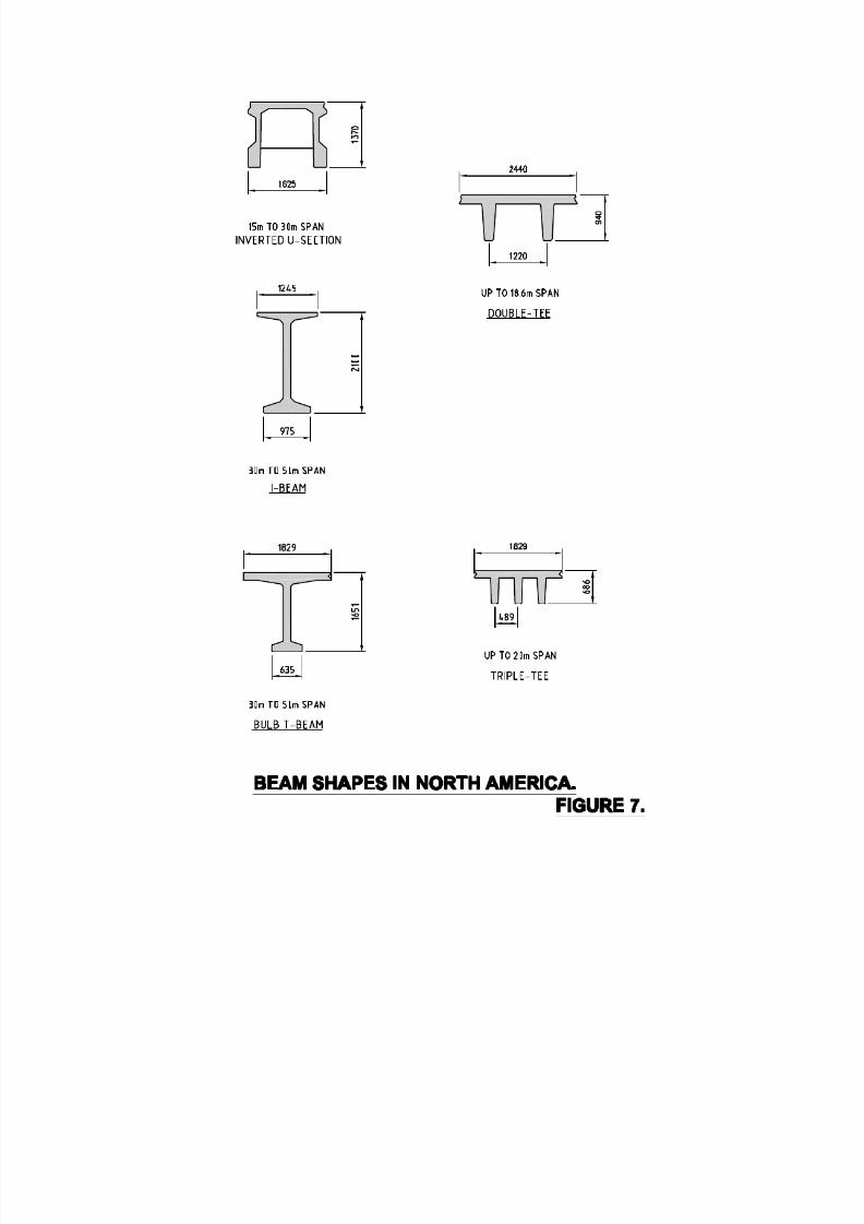
3.4.2 North American Beam Shapes and Practice
Table 3 and Figures 6 and 7 shows the range of beam shapes in use in North America.
Table 3 Current North American Practice
Span Range Precast Section Comments
Spans up to 20 m Solid planks, triple hollowcore planks, double hollowcore planks, doublerectangular voided planks,double “T” planks and triple“T” planks.
Wide variety of deck slabunits used for shorter spans.Preferences vary betweenstates. Most planks aretransversely post-tensioned oruse overlays.
Spans between 15 m – 30 m Bulb-Tee girders, “I” girders,inverted “U” beams, single
and twin cell box beams, and“FM” girders.
Similar sections used indifferent states. “I” girders
require insitu deck slab. Bulb-Tee girders are post-tensionedtransversely with insitu joints.“FM” girders require insitu
joints between webs.
Spans between 30 m – 50 m Bulb-Tee girders, “I” girders,inverted “U” beams, singlecell box beams and “FM”girders.
As above for 15 m to 30 mspans.
8/9/2019 Standard Bridge Beams
http://slidepdf.com/reader/full/standard-bridge-beams 21/67
21
3.5 Summary of Literature Review Findings
The literature review of the four countries showed that precast beams are extensivelyused in these countries and that many of the beam shapes and/or spans have been
updated or modified in recent years.
The scale and number of roading projects in North America has resulted in a wide rangeof bridge beam shapes some of which are far too long (and heavy) for use in NewZealand conditions. In the United Kingdom there was a lesser number of shapes, butlike North America some shapes span up to 40 metres and are specifically designed formotorway widening projects and therefore unlikely to be used on a regular basis in NewZealand due to the small number of long span bridges required.
Australia was considered the most relevant country to compare beam shapes not onlydue to its geographical proximity but also the scale of works in the individual Australian
states was similar to New Zealand.
Also, some of the shapes used were very similar to those used in New Zealand and theteam considered many of the factors applicable to the standard beam selection inAustralia were equally relevant to New Zealand.
8/9/2019 Standard Bridge Beams
http://slidepdf.com/reader/full/standard-bridge-beams 22/67
8/9/2019 Standard Bridge Beams
http://slidepdf.com/reader/full/standard-bridge-beams 23/67

8/9/2019 Standard Bridge Beams
http://slidepdf.com/reader/full/standard-bridge-beams 24/67
24
4 SURVEY OF NEW ZEALAND PRECAST PRESTRESSEDBRIDGE BEAM MANUFACTURERS
4.1 General
In order to understand recent trends in beam shapes and corresponding deck shapes andspans that have been manufactured over the past five years a national survey of precastmanufacturers was carried out.
A survey form, (see appendix 2), was designed to capture a range of data so that definiteconclusions could be reached about the deck types of recent highway bridgesconstructed in New Zealand. That is, bridges that were designed for the Transit HN-HO-72 highway bridge loadings. Information on non-standard designs, eg bridgesdesigned to a standard less than HN-HO-72 were not requested.
4.2 Survey Methodology
The survey form comprised a range of possible beam types (see Table 4 below) as aguide to the respondents.
• Beam types 1, 2, 4, 5, 6 represented those standard types which were residual fromthe original “red” book
• Items 3 and 4 were included to determine if composite deck sections were being
used.• Item 7 refers to a more recent shape introduced into New Zealand from Australia.
Essentially a variation on a spaced box shape deck section.
• Items 8 and 9 refer to a box section shape produced in the central north island region
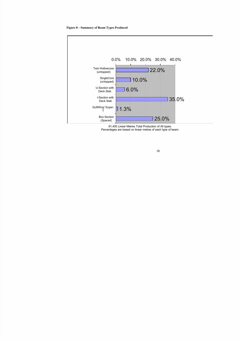
4.3 Survey Results
Survey responses were received from a total of 10 manufacturers of which two hadmultiple precast sites. Six were from the North Island and four from the South Island.See appendix 2. The survey results were split into six regional zones to determine if
there were regional trends or variations.
Data on 102 recently constructed bridges of six types was collected, those being thedouble hollow core, single hollow core, U and I section with deck slabs, gull wing andspaced box section.
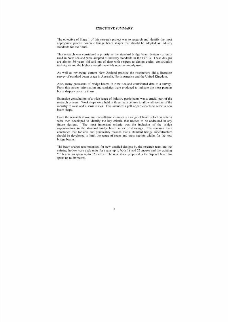
The trends from the survey are shown in Figure 8.

8/9/2019 Standard Bridge Beams
http://slidepdf.com/reader/full/standard-bridge-beams 25/67
25
Table 4 Existing Beam Types
Product
Type NºBeam Type Description
1 Double hollowcore deck unit (untopped)2 Single core deck unit (untopped)
3 Double hollowcore deck unit (topped)
4 Single circular core deck unit (topped)
5 U-Beam with deck slab
6 I-Beam with deck slab
7 Gull wing section/Super T
8 Box section not spaced
9 Box section spaced
4.4 Interpretation of results
These are detailed in full in Appendix 2.
The survey results show that the original MOW standards have been used on a regular basis over the last twenty to thirty years.
• The majority of responses indicated the popularity of double hollowcore (HC) bridge decks throughout all regions.
• Single (circular) hollowcore was popular with the north of the south island and inthe central north island.
• The I and U sections were used for bridges requiring longer spans, but have beenused to a lesser extent than the twin hollow core
• A variation on the popular double HC bridge decks is the large single rectangularcell box section shape which was used extensively on Route PJK in Tauranga.
4.4.1 Span/depth ratios
A comparison of the span/depth ratios against other authorities recommendations wascarried out to see if there were patterns of structural consistency. While the “I” beam,Super-T (or Gull Wing) and box section show a reasonably good comparison the doublehollow core units show a wide variation.
The survey indicated the popularity of the double hollow core unit as a standard unitwhich has provided highway bridge design flexibility and economic benefits during the
past thirty years.
8/9/2019 Standard Bridge Beams
http://slidepdf.com/reader/full/standard-bridge-beams 26/67
26
Figure 8 – Summary of Beam Types Produced
22.0%
10.0%
6.0%
35.0%
1.3%
25.0%
0.0% 10.0% 20.0% 30.0% 40.0%
Twin Hollowcore
(untopped)
SingleCore
(untopped)
U-Section with
Deck Slab
I-Section with
Deck Slab
GullWing/ Super-
T
Box Section
(Spaced)
61,400 Linear Metres Total Production of All types.Percentages are based on linear metres of each type of beam.

8/9/2019 Standard Bridge Beams
http://slidepdf.com/reader/full/standard-bridge-beams 27/67
8/9/2019 Standard Bridge Beams
http://slidepdf.com/reader/full/standard-bridge-beams 28/67
28
• Hollow core units – reflective cracking problems;
• Rideability for road users – the trend to continuous bridges;
• Expansion joints/bearings – minimise for rideability/maintenance;
• Curvature, skew and superelevation common in NZ bridges – flexibility needed;
• Edge protection requirements: new and existing bridges.
A large number of criteria for selection of beam shapes were identified, but thefollowing criteria were raised at two or more of the workshops.
• Use coastal B1 rating for durability and construction specification;
• Design for minimum maintenance – less joints, bearings;
• Emphasise standardisation and use of existing moulds;
• Prefer to minimise site form work and concrete;
• Accommodate proposed design code changes;
• Ensure flexibility in standard shapes:• Maximum range with 1 mould (able to be modified)
• One size/shape does not fit all
• Need a range of spans.
• Visual appearance of handrails and edge beams important for urban bridges.
The results of the informal poll of workshop participants showed a clear preference forthe Super-T/Tee-Roff as the proposed new standard shape and updating the existinghollow-core designs was the top priority for existing beam shapes. This is covered ingreater detail in section 6.3.
5.4 Summary of Consultation
Overall, a large number of specialist bridge engineers and technical staff participated inthe consultation process.
Extensive consultation was a crucial part of the research process and valuable commentsand ideas were received from bridge clients (such as Transit), consultants, bridgingcontractors and precasters.
Nearly 40 industry representatives attended the three consultation workshops and thisface to face contact and discussion ensured we were fully aware of the views of
individual industry participants.
By consulting widely over the whole bridging industry we believe the consultation process has been robust and has crucially assisted the research team in selecting newstandard beam shapes which will be widely accepted and used on a regular basis.
8/9/2019 Standard Bridge Beams
http://slidepdf.com/reader/full/standard-bridge-beams 29/67
29
6 ANALYSIS OF RESEARCH RESULTS
6.1 General
Unlike a subject with easily answered yes or no questions, this project required carefuldiscussion and debate on the views and preferences raised both from the consultation
process and the various team members. The analysis of the results of the researchfindings is summarised below for both the preferred beam shapes and the key criteriafor the selection of beam shapes.
6.2 Preferred Standard Beam Shapes
The poll of possible beam shapes provided definitive results. The workshop attendeeswere asked to select one existing and one new shape from the beam shapes commonly
used in New Zealand, Australia, Great Britain and North America.
The results of the poll (combined from the three workshops) were as follows:
Existing Standard Beam Shapes
Double Hollow Core 25 votesSingle Hollow Core 5 votesI-Section 6 votesU-Section 3 votes
New Standard Beam Shapes
Super-T/Tee-Roff 22 votesDouble-T 1 vote
On the basis of the poll results, retention of the double hollow core deck units and the“I” beams were preferred from the existing beam shapes, and were marginally ahead ofthe single hollow core deck units. The Super-T/Tee-Roff beam from Australia wasselected as the new beam shape.
6.3 Criteria for Selecting New Standard Beam Shapes
Criteria for selecting new beam shapes for use in New Zealand have been developedduring this project and have been used in the selection process. The criteria wheregrouped into the following key areas:
• Product type and span range
• Design and aesthetics
• Beam manufacture
• Construction
• Maintenance

8/9/2019 Standard Bridge Beams
http://slidepdf.com/reader/full/standard-bridge-beams 30/67
30
• Client requirements
The full criteria under each of these areas are:
Product Type and Span Range:
• Flexibility – can the same shape be used for a wide range of beam depths/spacings
• Span range – does the beam shape cater for a wide range of spans
Design and Aesthetics:
• Beam depth – are beams shallow in depth to suit limited headroom situations and toreduce approach embankment height
• Skew – can beams be used where high skews are required
• Continuity – can beams be made continuous at piers/integral with abutments
• Transverse behaviour – do beams provide good load spreading between beams
• Design codes – have beams been designed for overseas codes with differentrequirements to New Zealand
• Torsional capacity – are beams torsionally efficient
• Structural efficiency – are beams structurally efficient measured on cost per squaremeter basis including deck slab/topping
• Diaphragms – are transverse diaphragms required at beam ends and intermediatelocations
• Vibration/deflection – are beams stiff enough to use in urban areas with footpaths
• Stressing – are beams pre-tensioned only or is additional post-tensioning required
• Appearance – do beams have good appearance without the need for special edgeunits or insitu masking
• Edge protection – can beams cater for new edge protection requirements
• Services – can services be accommodated within the beam shape without specialservice ducts being provided
• Curvature – can beams be used on a deck with a curved alignment.
Beam Manufacture:
• Beam weight – what are lifting requirements and are they within New Zealand crane
capacity• Cost of forms
o Do forms already existo Are forms difficult/expensive to makeo Are forms robust
• Steel fixingso Is reinforcement difficult to fixo Is large quantity of reinforcement requiredo Are there congestion problems
8/9/2019 Standard Bridge Beams
http://slidepdf.com/reader/full/standard-bridge-beams 31/67
31
• Handling – are beams robust for handling, torsionally stiff and resistant to impactdamage
• Casting of beams – can concrete be placed adequately
• Strand types – are strand types readily available in New Zealand
• Concrete grades – are concrete plants capable of producing required grades ofconcrete in New Zealand.
Construction:
• Cost effectiveness – are beams cost effective on a cost per square metre of deck
• Slab formwork – is temporary or permanent formwork required to support the deckslab or does the precast beam act as permanent formwork
• Diaphragms – are diaphragms difficult to install
• Stability during erection – are beams stable during erection, or are temporary
supports required.
Maintenance:
• Durability – are beams well detailed to provide good long term durability
• Water penetration – do beams have joints that will allow water to penetrate the deckleading to deterioration of structural elements
• Inspection – can exposed surfaces be easily inspected (adequate gaps betweenflanges).
Client Requirements:
• Design life – can the specified 100 year design life be achieved
• Expansion joints – can they be eliminated
• Maintenance – can a low maintenance bridge be provided.
The attendees at the consultation workshops were asked to rank a small number of thecriteria which they considered important. The results were then summarised in tabularform and those issues that had been raised at more one workshop were markedaccordingly.
The workshops indicated that the most important criteria in selecting new beam shapesfor New Zealand were:
• Flexibilityo Maximise span range with one mouldo Range of spans is required up to 35 metreso Range of Beam Types should provide for curved bridges
• Appearance – particularly of beam edge and handrail
• Durability – include for coastal areas as well as inland
• Maintenance – minimise joints and bearings
8/9/2019 Standard Bridge Beams
http://slidepdf.com/reader/full/standard-bridge-beams 32/67
32
• Costo Design for minimum maintenanceo Minimise cost per square metre of deck
• Beam weight – 40 tonnes maximum, 20 tonnes preferred
• Depth limitations – need a variety of different beam depth solutions• Beam moulds
o Need standardisation and use of existing mouldso One new shape only due to high cost of replacing moulds
• Beam web thickness – 140 mm preferred minimum.
Other key comments obtained from the industry consultation that influence the selectionof beam shapes and the approach to be taken to their design include:
• The designs should provide for future design code changes
•Full standard designs are preferred over standard shapes requiring design on a project by project basis
• Adopt best practice from overseas where possible
• Minimise site formwork and concrete work where possible
• Provide for continuity over piers
• “I” beams are useful for rural areas and are versatile for curved bridges and highsuper elevation.
Following the consultation with industry the key design criteria to be adopted forselection of the new beam shapes were determined to be:
• Flexibility• Cost
• Durability/maintenance
• Standardisation of shapes
• Beam weight
• Beam depth
• Appearance
• Minimisation of site work
These criteria have been adopted as the key criteria for the selection of new beam
shapes. The selection of the new beam shapes is described in section 6.4 below.
6.4 Selection of New Beam Shapes
The selection of new beam shapes to replace the existing standard beams has beenundertaken on the following basis:
• Review of existing beam shapes currently used in New Zealand
• Review of other beam shapes currently used in New Zealand

8/9/2019 Standard Bridge Beams
http://slidepdf.com/reader/full/standard-bridge-beams 33/67
33
• Review of alternative beam shapes currently used overseas and assessment ofwhether these shapes would be suitable for use in New Zealand
• Selection of new beam shapes on the basis of feedback obtained from industryconsultation on preferences for new beam shapes and the criteria that are most
important in selecting the new beam shapes
6.4.1 Review of Existing Standard Beam Shapes
The review of the current situation in New Zealand with respect to standard bridge beams has identified the following key points:
• The existing standard bridge beams are becoming out of date
• Some of the beam types and span ranges are now rarely used as they are consideredto be uneconomic due to their method of construction and cost of manufacture
• Changing design standards for bridge width, live loading (proposed), durability andedge protection, and new methods of design such as the use of a partial prestressapproach need to be incorporated
• Some of the standard beams have maintenance issues
The key issues with respect to each of the current shapes are:
• Single hollow core units – rarely used except for some individual precastmanufacturers as considered uneconomic compared to double hollow core units
• Double hollow core units – still widely used and considered economically
competitive for spans of between 10 and 18 metres, and occasionally up to 20metres, but have some maintenance issues, particularly when used for longer spans.Some alternative void shapes are used.
• Triple hollow core units – rarely used as considered uneconomic compared todouble hollow core units
• “I” beams – still widely used for spans up to 25 metres, but maybe uneconomic forlonger spans
• “U” beams – used for urban bridges where headroom is limited, but generallyconsidered uneconomic (due to its heavy weight) compared to “I” beams and someother shapes.
In summary, the double hollow core units and “I” beams are still very popular and seemto provide both buildable and economic solutions. However, they need to be improvedwith respect to the changes to design standards that have occurred since they were lastupdated, and any maintenance issues addressed. The “U” beams are still used, but dueto their lack of economy are unlikely to be worth updating. The other beam shapes arerarely used and there seems to be little point in updating them.

8/9/2019 Standard Bridge Beams
http://slidepdf.com/reader/full/standard-bridge-beams 34/67
34
6.4.2 Review of Other Beam Shapes Currently Used in New Zealand
Other shapes that have been used in New Zealand in recent times are known to include:
• Hollow core units with single rectangular void 650 mm deep unit spanning up to 18metres
• Hollow core units with single rectangular void 900 mm deep spanning up to 25metres
• Super-T beams
The above beams have been used on an individual project basis with design undertakenfor each individual bridge. The 650 mm deep hollow core units with a single rectangularvoid are understood to offer economic advantages related to the ease of manufacture.They use a steel internal form that is cheaper than the polystyrene voids used in thedouble hollow core units, and more reliable to hold in place. The 900 mm deep hollowcore units have been used as an alternative to both “I” beams and “U” beams for spansup to 25 metres. They are understood to offer economic advantages due to theirstructurally efficient section and ease of construction, with no deck slab being required.
The Super-T (and Tee-Roff) beams have been used as an alternative to both “I” beamsand “U” beams for spans in the range of 20 to 25 metres. They offer advantages ofstructural efficiency and ease of construction with the outstand wings providing a
permanent form for the insitu concrete deck slab. They also provide an attractive boxshape that can be used in a variety of situations and are comparable in this respect to thestandard “U” beams. The disadvantages of this shape relate to their ability to cater for
curved bridges and bridges with significant warping, in which the units need to bestepped at their longitudinal joints between beams. Again, these have been designed onan individual bridge basis.
Clearly the alternative beam shapes that are currently being used in New Zealand havedemonstrated some advantages over the existing beam shapes as they have beenselected instead of the existing shapes for a number of projects. These beam shapesshould be investigated further as possible new standard bridge beams to be used in NewZealand.
6.4.3 Review of Beam Shapes Currently Used Overseas
From the international literature search of current overseas practice, covering Australia,UK and North America, the range of beam shapes that are currently used is very wideand differs significantly between countries. Within Australia and North America thereare significant differences in the shapes used between different states.
The main beam shapes used overseas are considered for use in New Zealand as follows:
8/9/2019 Standard Bridge Beams
http://slidepdf.com/reader/full/standard-bridge-beams 35/67
35
Australia
Australian practice varies between states, but generally the beam shapes described insection 3.2 are used over the entire country with some local variations. Beams are
designed for similar loading and environmental conditions to New Zealand and practiceis generally to provide standard designs with full details.
In summary, practice for short span bridges is similar to that in New Zealand with precast plank units commonly used, except that structural overlays are used as analternative to transverse prestress in some states. For longer spans, the Super-T beamsare now the beams of choice and seem to offer real advantages of economy and
buildability, as well as having good appearance .
It is considered that the use of structural overlays for hollow core deck units as analternative to transverse prestress, and the use of Super-T beams for longer spans,
should be considered for use in New Zealand.
United Kingdom
United Kingdom practice has traditionally been to use beam with insitu infills forshorter spans and beam and slab for longer span ranges. Design loadings andenvironmental conditions very considerably from those in New Zealand, with farheavier design loads and more severe environmental conditions.
The standard bridge beams were re-engineered in the early 1990’s. This led to beamsthat are easier to manufacture and with a greater span range than the earlier designs. Thecurrent shapes that are used are described in section 3.3.
UK practice is for beam shapes and strand positions to be standardised, but for each bridge to be individually designed. The new range of shapes offer beams that arestructurally efficient and that offer advantages in beam manufacture and construction.The beams generally appear to be of heavy proportions, reflecting concerns aboutconcrete placing that existed with the previous standard beam designs, and the heavydesign loading. Concrete covers are also generally greater in the UK than New Zealanddue to the use of de-icing salts and freeze-thaw conditions.
It is considered that while the UK beam shapes are well engineered and are likely tooffer economic and buildable solutions, they are probably not appropriate for NewZealand due to the philosophy of using beam and slab/insitu infill construction for allspans, and the differences in design criteria. Adoption of the UK beams would require aradically different approach to that historically taken in New Zealand and a completenew start with respect to beam manufacture and construction practice. It is consideredunlikely that the industry would support such an approach, or that the country wouldwant to pay for the required investment in new moulds.
8/9/2019 Standard Bridge Beams
http://slidepdf.com/reader/full/standard-bridge-beams 36/67
36
North America
North American practice varies widely between states. The traditional use of ASSHTO“I” girders has gradually been replaced by a new generation of “I” and Bulb-Tee girders
that have been re-engineered to improve their economy, extend their span range and insome states utilise higher strength materials. Current practice is summarised in section3.4.
Generally, standard beams are fully designed and detailed in North America with moststates being responsible for the development of new designs. The focus in recent yearsappears to have been on engineering longer span (>30 metres span) beams and inimproving the efficiency of the beams. The shorter span beams using precast planks andI girders are very similar to those currently used in New Zealand. Loadings andenvironmental conditions in North America vary, but in some states are similar to NewZealand.
In view of the similarities of beams used for the shorter spans to those already availablein New Zealand, and the major investment that would be required to change the shapeof the “I” beams, it is considered unlikely that any of the beams currently available in
North America would offer substantial advantages for use in New Zealand over theexisting shapes. The longer span beams that are used in North America are not routinelyneeded in New Zealand and lifting and transporting such heavy beams is likely to be
beyond readily available craneage capacity.
It is therefore considered that none of the North American beam shapes offer solutionsfor New Zealand standard beams, in the light of the similarities of the available beamshapes with those already used in New Zealand, and the high cost of modifying the
beam moulds to suit the new shapes.
6.4.4 Selection of Beam Shapes
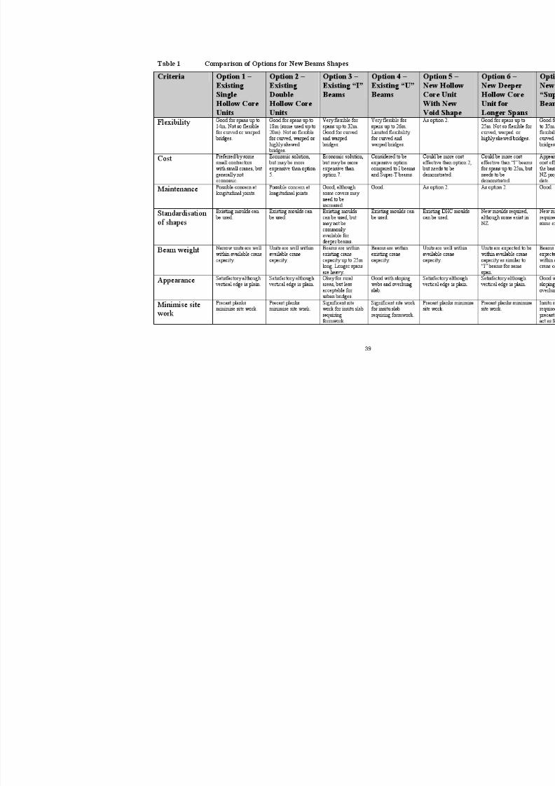
Options have been identified for new beam shapes to be used in New Zealand from thereview of the current standard bridge beams, the alternative beam shapes currently
being used in New Zealand, and current international practice, and from the preferencesexpressed by attendees at the industry workshops. The options identified are:
•
Option 1 – Retain the single hollow core deck unit currently used in New Zealandand modify the design to cater for changes in design standards
• Option 2 - Retain the double hollow core deck units currently used in New Zealandand modify the design to cater for changes in design standards
• Option 3 - Retain the “I” beams currently used in New Zealand and modify thedesign to cater for changes in design standards
• Option 4 – Retain the “U” beams currently used in New Zealand and modify thedesign to cater for changes in design standards
• Option 5- Introduce a hollow core deck unit with a different void shape to simplifymanufacture and improve cost effectiveness using a variety of unit depths to caterfor different spans up to 18 metres

8/9/2019 Standard Bridge Beams
http://slidepdf.com/reader/full/standard-bridge-beams 37/67
37
• Option 6 – Introduce a deeper hollow core unit than currently used to extend thespan range up to 25 metres to provide an alternative to the current “I” beams and“U” beams
• Option 7- Introduce the Super-T or Tee-Roff beam unit that is currently widely used
in Australia, and that has been used in New Zealand on some projects, with a varietyof beam depths to cater for various spans up to 30 metres.
All of the above options are based on the range of selected shapes covering a span rangefrom 12 to 30 metres.
These options reflect the results of the poll undertaken at the industry workshops inwhich the retention of the double hollow core units was the preferred option for theexisting beam shapes by a significant margin, followed by retention of the “I” beamsand single hollow core units. Of the new shapes from overseas, the Tee-Roff beam fromAustralia was preferred by a significant margin over any other beam shape.
These options have been analysed against the key criteria identified from the industryworkshop. The results are given in Table 5.
We only consider it practical to develop and maintain a limited number of standard beam shapes in New Zealand, because of the relatively small number of new bridgesthat are constructed, which limits the demand for any particular beam shape. In turn,this limits the number of different mould shapes than can be available due to the highcost of establishing new moulds and maintaining existing ones. There are also limits onthe amount of money that can be invested in the design of new beams and maintenanceof existing designs.
We therefore consider it practical to have only three or four beam shapes in operation,compared to the existing five beam types. We consider that, on the basis of the
preferences for beam shapes expressed by industry at the workshops, and the analysis ofthe shapes against the key criteria for new beam shapes selected by the participants, thatoptions 2, 3, 5, 6 and 7 should be chosen for further study. Options 2 and 5 arealternatives that require further assessment before a final decision on void shape ismade.
6.4.5 New Standard Beam Shapes Proposed
The new beams shapes proposed covering the span range from 12 to 30 metres aretherefore:
• Hollow core deck units 1144 mm wide for spans up to 18 metres with either doublecircular voids or single rectangular void to be determined during the detailed designstage (with further industry consultation required)
• Hollow core deck unit for spans up to 25 metres, with void shape to be determinedduring the detailed design stage
• Existing “I” beams for spans up to 32 metres, updated for changes to designstandards
• Super-T beams for spans up to 30 metres.

8/9/2019 Standard Bridge Beams
http://slidepdf.com/reader/full/standard-bridge-beams 38/67
38
We propose that the existing single core deck units and “U” beams are not updated asnew standard shapes.
8/9/2019 Standard Bridge Beams
http://slidepdf.com/reader/full/standard-bridge-beams 39/67
8/9/2019 Standard Bridge Beams
http://slidepdf.com/reader/full/standard-bridge-beams 40/67
40
7 PRELIMINARY DESIGN OF NEW BEAM SHAPES
7.1 General
Preliminary design has been undertaken for the proposed new beam shapes to determinethe basic parameters for the new beams. These include the span range, beam depth,
beam cross section, deck slab thickness, maintenance issues and material strengths. Forthe existing beams that are to be retained and updated, the preliminary design alsoaddresses the changes to design standards and the any other issues that need to beconsidered.
The preliminary design considers the full superstructure for a particular beam, includingthe deck slab, diaphragms, joint details and seismic connection to the piers andabutments.
7.2 Criteria for a Standard Bridge Superstructure
The existing standard bridge beams cater for a wide range of spans of between 8 and 32metres and for a variety of bridge widths from a single lane bridge to a two lane bridgewith footways. To achieve a practical output from this project, we considered it wasnecessary to limit the range of spans and cross section widths for the new bridge beams,and to agree criteria for other design standards to be adopted.
The proposed design criteria for the standard bridge beams are:
• Two lane rural highway bridge without footways (extra beams can be added to provide footways with little additional design effort) giving overall bridge deckwidth of 11.4metres (2 x 3.5 metre lanes plus 1.2 metre wide shoulders and 1.0metre wide barrier edge width)
• 100 km/hr design speed
• HN-HO-72 design live loading (as modified by the proposed revision to theserviceability loading currently being considered)
• Test Level 4 edge protection (typical requirement for rural bridge with low trafficvolumes) assuming flexible barrier requiring 1.0 metre edge distance
• Class B1 durability to NZS 3101 for coastal perimeter, but excluding coastal
frontage (class B2)• Square span which will cater for skew up to about 15 degrees without special
analysis
• Zero tension design (partial prestress approach will reduce the amount of prestressand will be used in the Stage 2 detailed design to give greater economy)
• Design meets the requirements of Transit New Zealand Bridge Manual
• Span range from 12 to 30 metres.
These criteria have been used for the preliminary design of the proposed new bridge beams. The proposed standard bridge cross-section is shown in Figure 9.

8/9/2019 Standard Bridge Beams
http://slidepdf.com/reader/full/standard-bridge-beams 41/67
8/9/2019 Standard Bridge Beams
http://slidepdf.com/reader/full/standard-bridge-beams 42/67
42
7.3 Hollow Core Beams
7.3.1 General
The preliminary design of the hollow core deck units has considered the followingdesign issues:
• Span range and unit depths
• Width of hollow core units to suit standard bridge width
• Void shape – circular or rectangular
• Concrete strength
• Transverse design – transverse prestress or structural overlay slab
• Longitudinal joints between units
• Maintenance issues
The findings of the preliminary design are described below.
7.3.2 Span Range and Unit Depths
The existing double hollow core designs cover a wide range of spans between 8 m and18 m and use three different unit depths as follows:
• 458 mm deep unit, 914 mm wide – spans 6 m to 12 m
• 576 mm deep unit, 1144 mm wide – spans 12 m to 16 m
• 650 mm deep unit, 1144 mm wide – spans 16 m to 18 m
The maximum span/depth ratio varies between 26.2 for the 458 mm deep unit and 27.7for the 576 mm and 650 mm deep units.
Since spans below 12 metre are only rarely used, it is proposed that the followinghollow core units should be provided:
• 576 mm deep unit - spans 12 m to 16 m
• 650 mm deep unit - spans 16 m to 18 m
• 900 mm deep unit - spans 18 m to 25 m
The 900 mm deep unit will have a span/depth ratio of 27.7, consistent with the existingdesigns.
7.3.3 Width of Units
The existing deck units are 1144 mm wide and were developed at a time when thestandard bridge width was less than required for the present bridge width standards. The1144 mm wide unit gives a modular width of 1150 mm between centres of joints.
8/9/2019 Standard Bridge Beams
http://slidepdf.com/reader/full/standard-bridge-beams 43/67
43
For the standard bridge width of 11.4 metres, the 1144 mm unit width would require 9.9units. Reducing the unit width to 1140 mm would rationalise the number of unitsrequired to exactly 10 units.
We consider that the existing unit width will probably be retained due to the cost ofmodifying the beam moulds, and as the difference between the required width for thestandard bridge and the width provided by the existing units is only 100 mm. This will
be further considered and finalised at the detailed design stage.
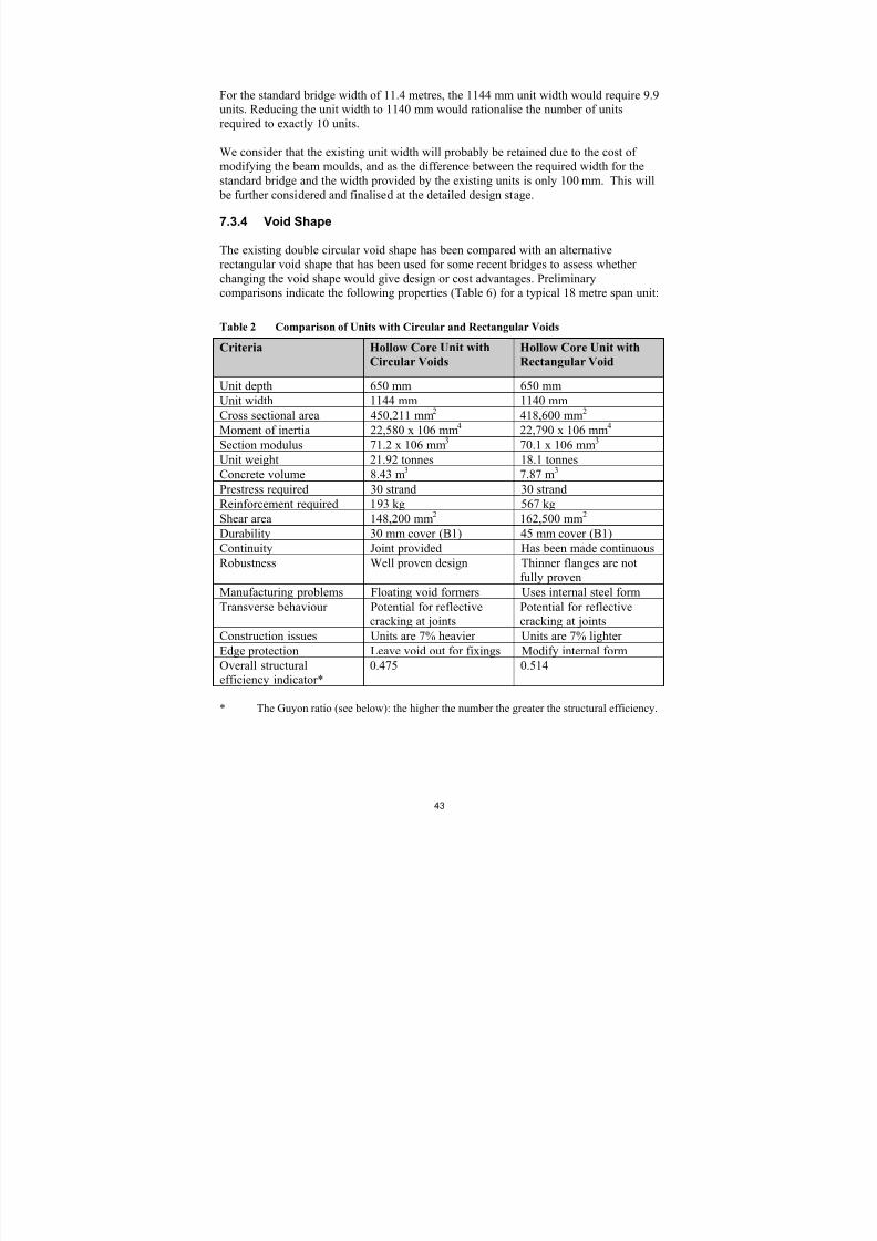
7.3.4 Void Shape
The existing double circular void shape has been compared with an alternativerectangular void shape that has been used for some recent bridges to assess whetherchanging the void shape would give design or cost advantages. Preliminarycomparisons indicate the following properties (Table 6) for a typical 18 metre span unit:
Table 2 Comparison of Units with Circular and Rectangular Voids
Criteria Hollow Core Unit with
Circular Voids
Hollow Core Unit with
Rectangular Void
Unit depth 650 mm 650 mm
Unit width 1144 mm 1140 mm
Cross sectional area 450,211 mm2 418,600 mm2
Moment of inertia 22,580 x 106 mm4 22,790 x 106 mm4
Section modulus 71.2 x 106 mm3 70.1 x 106 mm3
Unit weight 21.92 tonnes 18.1 tonnesConcrete volume 8.43 m3 7.87 m3
Prestress required 30 strand 30 strand
Reinforcement required 193 kg 567 kg
Shear area 148,200 mm2 162,500 mm2
Durability 30 mm cover (B1) 45 mm cover (B1)
Continuity Joint provided Has been made continuous
Robustness Well proven design Thinner flanges are notfully proven
Manufacturing problems Floating void formers Uses internal steel form
Transverse behaviour Potential for reflectivecracking at joints
Potential for reflectivecracking at joints
Construction issues Units are 7% heavier Units are 7% lighter
Edge protection Leave void out for fixings Modify internal form
Overall structuralefficiency indicator*
0.475 0.514
* The Guyon ratio (see below): the higher the number the greater the structural efficiency.

8/9/2019 Standard Bridge Beams
http://slidepdf.com/reader/full/standard-bridge-beams 44/67
44
Overall, the unit with circular voids has a slightly greater cross sectional area than therectangular voided unit but because of the void shape the moment of inertia and sectionmodulus are similar. The rectangular voided section is more structurally efficient usingthe Guyon ratio, which is calculated as:
P = r 2/yt.yb where r = radius of gyration.
The prestress required is similar in both sections whilst the rectangular voided sectionrequires less concrete but a greater quantity of reinforcement.
The rectangular voided section is also understood to be easier to manufacture due to theuse of a steel void former that is withdrawn laterally, rather than polystyrene void formswhich are known to be difficult to place and need to be heavily restrained to avoidflotation problems.
We considered that the rectangular voided unit may offer some manufacturing and costadvantages over the circular voided section, but that further detailed analysis will benecessary before a final choice can be made. In particular, analysis of the rectangularvoided section for distortion effects in the box cross section will be required to ensurethat there are no long term structural concerns with this shape. This will be undertakenduring the detailed design stage.
7.3.5 Concrete Strength
The existing hollow core deck units use concrete with a 28 day strength of 40 MPa.Transfer of prestress is allowed at 30 MPa. Some alternative designs use higher grade
concrete to allow earlier transfer of prestress.
A concrete strength of 40 MPa is adequate structurally for the units and allows adequatedurability to be achieved for a B1 exposure.
We therefore propose that 40 MPa concrete is retained for the design of the units unlessthe industry advise that earlier strength gain is a significant advantage to themanufacture of the units.
7.3.6 Transverse Design
The original design of the hollow core bridge decks was based on the premise that thedeck units would share load transversely by shear transfer across the longitudinal joints.The joints were detailed to behave as “pinned” joints with grout only provided over partof their depth. The analysis of the time assumed pinned connections between units todetermine the distribution of loading between the deck units. Inherent in this assumptionis the expectation that the joints between the deck units will crack under transverse
bending effects. It is considered unlikely that this approach would be justified to currentconcrete code requirements, which limit permitted crack widths.

8/9/2019 Standard Bridge Beams
http://slidepdf.com/reader/full/standard-bridge-beams 45/67
45
From consultation with the industry we understand that there have been some instanceswhere reflective cracking has occurred in the road surfacing above the longitudinal
joints, and that this has given rise to maintenance concerns. This has been addressed onan individual project basis by providing additional transverse prestress, providing
continuous prestress ducts to protect the tendons and by increasing the depth of thegrouted joints so that the joint behaves more as a monolithic connection. This concern is
believed to have mainly occurred with longer span units.
An alternative method of transverse connection between the deck units is to provide acast insitu overlay slab on top of the units instead of transverse prestressing. Overlaysare commonly used in Australia where the insitu slab is made composite with the
precast deck units. Provision of an overlay slab is likely to reduce the structuralefficiency of the precast deck units and increase the cost of the bridge deck compared toa fully precast solution.
The three options to improve the design of the hollow core deck units with respect totheir transverse design are therefore:
• Increase the transverse prestress, provide continuous ducts and increase the depth ofthe grouted joints between deck units
• Provide a structural overlay slab composite with the deck units.
Preliminary design indicates that increasing the transverse prestress, providingcontinuous ducts and increasing the depth of the grouted joints between units is likely to
provide the most cost effective solution for the hollow core deck units, since the provision of an overlay slab will increase the cost of construction due to a reduction instructural efficiency for the deck units and an increase in site construction work.
We recommend that the transverse prestress option should be selected for the detaileddesign.
7.3.7 Longitudinal Joints Between Units
The existing detail for the joint between hollow core deck units provides a grouted jointwith a profiled shear key formed in the sides of the abutting deck units. The joint istypically less than half the depth of the unit.
The maintenance concerns that have been described above in which reflective crackinghas been found to occur on some longer span bridges, have been in part attributed to thedetailing of the joints between units. Modifications have been made on an individual
project basis to improve the performance of the joint by increasing its depth so that 75%or more of the unit depth is grouted. The dimensions of the shear keys have also beenincreased, and in some cases non-shrink grout has been used. The performance of thelongitudinal joint is also improved by the additional transverse prestress described in7.3.6 above.
8/9/2019 Standard Bridge Beams
http://slidepdf.com/reader/full/standard-bridge-beams 46/67
46
We recommend that the longitudinal joints between deck units be modified for the newstandard beam shapes for hollow core deck units to increase the depth of the grouted
joints, and that the specification for the grout should be reviewed. The transverse prestress should also be increased as described in 7.3.6.
7.3.8 Maintenance Issues
Maintenance issues that have been identified in relation to the existing hollow coredesigns include:
• Concrete cover and provision of adequate durability to meet current standards
• Reflective cracking above longitudinal joints
• The durability of the sealed joints at the end of the deck units
The existing cover provided is 30 mm to exposed surfaces. This is adequate to provide a100 year design life to meet the Bridge Manual requirements for class B1 exposure, asrequired for the standard bridge. No changes are therefore proposed to the concretecover for the existing standard designs.
The issue of reflective cracking has already been addressed in section 7.3.6 above.
The durability of the sealed joints at the end of the hollow core units where they connectto either abutments or pier cap beams will be addressed in the detailed design stage.
7.3.9 Summary of Findings
The preliminary design of the hollow core deck units for the new beam shapes hasconcluded the following:
• Hollow core units should be provided for spans of between 12 and 25 metres usinghollow core units of 576 mm, 650 mm and 900 mm depth
• The precast industry would like the existing 1144 mm unit width to be retained.This would appear to fit the current Transit Bridge Manual range of widthrequirements based on the standard bridge criteria developed as part of this project.
This will be confirmed during the detailed design stage.• Twin or single voids should be provided, the final void shape to be confirmed
during detailed design
• Concrete strengths of 40 MPa should be used unless the precast industry advises thatthere are manufacturing advantages to using higher concrete strengths for earlystripping
• The transverse design should be improved by increasing the amount of transverse prestress, providing continuous ducts and increasing the depth of the grouted joints between units
• Concrete covers are adequate for long term durability
8/9/2019 Standard Bridge Beams
http://slidepdf.com/reader/full/standard-bridge-beams 47/67
47
• Joint details at the ends of the deck units should be reviewed during detailed design
7.4 “I” Beams
7.4.1 General
The preliminary design of the “I” beams has considered the following design issues:
• Beam spacing in relation to increased deck widths
• Beam shape
• Concrete strength
• Edge protection requirements
• Durability.
The findings of the preliminary design are described below.
7.4.2 Beam Spacing
The existing standard bridge beam designs indicate that the spacing of the “I” beams is2.3 metres. The original design of the beams was based on the beam spacing to increaseto 2.5 metres when wider bridge decks were required.
For the standard 11.4 metre wide bridge, preliminary design indicates that five beamswill be required (compared to four beams at present) at a spacing of 2.3 metres, withouter cantilevers of 1.1 metres. This will allow the existing deck slab thickness to be
maintained.
The existing “I” beam designs will therefore be modified for the wider bridge deck. The bridge deck slab will require re-design to cater for the additional beam and increased barrier loads.
7.4.3 Beam Shape
The research of current international practice and in particular North America, hasindicated that development of new “I” beam shapes has taken place in recent years.Comparison of these new “I” beam shapes with the existing New Zealand “I” beams hasshown that the new shapes are similar in shape but tend to have wider top flanges andare shallower in depth for a particular span. Bottom flanges shapes and web dimensionsare similar to the existing New Zealand shapes.
The main difference with the new beam shapes is that the new beams have a greaterspan range and go well beyond what is currently used in New Zealand. Prestress andreinforcement details have not been studied in depth, but may show that the new beamsare more economical than the existing beam shapes through refinement of the designmethod.
8/9/2019 Standard Bridge Beams
http://slidepdf.com/reader/full/standard-bridge-beams 48/67
48
We propose that as the existing “I” beams in New Zealand are very similar to the newshapes available in North America for the span ranges currently available (up to 32metres), there is little point in adopting the new beam shapes as this would requiresignificant investment in new beam moulds and in re-design of the beams. This is
reinforced by the views expressed in the industry consultation findings that the existing“I” beams should be retained, but that a new shape in the form of the Tee-Roff beamshould be introduced for spans up to 30 metres.
We therefore propose that the existing “I” beam shapes should be retained and updatedfor changes to design standards that have occurred where the existing designs would beinadequate.
7.4.4 Concrete Strength
The existing “I” beams use concrete with a 28 day strength of 40 MPa. Transfer of
prestress is allowed at 30 MPa for pre-tensioned beams and 35 MPa for post-tensioned.The insitu deck slabs use 25 MPa concrete.
A concrete strength of 40 MPa is adequate structurally for the “I” beams and it isunderstood that adequate formwork stripping times are also achieved. The 25 MPa deckconcrete is also adequate for the deck slab design.
It is therefore considered that 40 MPa concrete is retained for the design of the “I” beams, and that the deck slab concrete be kept as 25 MPa at 28 days, on the basis ofstructural considerations.
7.4.5 Edge Protection Requirements
The Test Level 4 (TL4) edge barrier proposed for the standard bridge can be supported by the existing 180 mm thick deck slab provided for the “I” beam standard design. It istherefore not necessary to increase the deck slab unless a higher level of side protectionis to be provided for a particular bridge, above TL4.
7.4.6 Durability
A concrete strength of 40 MPa for the “I” beams allows adequate durability to be
achieved for class B1 exposure with the existing 30 mm cover to reinforcement. For thedeck slab the existing cover of 40 mm is below the 50 mm cover necessary for class B1exposure with 25 MPa concrete. Changing the deck slab concrete to 30 MPa at 28 dayswould meet the class B1 durability requirements. It is not considered practical toincrease the cover to reinforcement without increasing the deck slab thickness, which isundesirable.
It is therefore considered that 40 MPa concrete is retained for the design of the “I” beams, and that the deck slab concrete be increased to 30 MPa at 28 days to meetdurability requirements.
8/9/2019 Standard Bridge Beams
http://slidepdf.com/reader/full/standard-bridge-beams 49/67
49
7.4.7 Summary of Findings
The preliminary design of the “I” beams for the new beam shapes has concluded thefollowing:
• The standard bridge will need to be re-designed to cater for the additional beamrequired to suit the increased bridge width and for the increased edge barrier loads
• The existing “I” beam shapes should be retained and not replaced by the new “I” beam shapes that have been developed overseas
• Concrete strengths for “I” beams and deck slab are adequate structurally
• The existing 180 mm thick deck slabs are of adequate thickness to cater for the proposed Test Level 4 edge protection on the standard bridge
• The concrete strength for the deck slab should be increased to 30 MPa to ensure thatthe slab has adequate durability for class B1 conditions. The “I” beams haveadequate durability with the specified 40 MPa concrete.
7.5 Super-T Beams
7.5.1 General
The preliminary design of the Super-T beams has considered the following issues:
• Span range for the various depths of unit
• Flange width & beam spacing
• Top slab depth
• Concrete Strength
• Prestressing
• Edge protection
• Durability
• Maintenance
The findings of the preliminary design are described below.
7.5.2 Span Range for the various depths of unit
The preliminary design has assumed that the typical beam depths for the various spanlengths used in Australia are appropriate for New Zealand. This assumption isconsidered reasonable because AUSTROADS loadings generally produce similareffects to the loadings in the Transit NZ Bridge Manual. The assumption is also backedup by recent design experience on Super T bridges in New Zealand.

8/9/2019 Standard Bridge Beams
http://slidepdf.com/reader/full/standard-bridge-beams 50/67
50
Typical span ranges for the various units are as follows:
Depth Span750 mm 15 to 20 m
1000 mm 20 to 25 m1200 mm 25 to 30 m1500 mm 30 to 35 m
7.5.3 Flange Width and Beam Spacing
The width of the flanges on the Super-T beams can be varied to give an over-all widthof section ranging from a minimum of 1200 mm to a maximum of 2500 mm. For the11.4 metre wide standard bridge this would equate to five beams of 2.28 metres width.
7.5.4 Top slab Depth
Typical depth thicknesses range from 160 mm to 200 mm. For the preliminary design, a160 mm thick top slab has been assumed. This will need to be confirmed in the detaileddesign. Initial calculations indicate that the critical load case for the design of the slab islikely to be the TL4 barrier loading.
7.5.5 Concrete Strength
(a) Prestressed Beam
It is proposed to base the detailed design on a 28-day concrete strength of 40 MPa andstrength at transfer of 30 MPa. Recent design work using the Super T shape indicatesthat the above strengths are likely to be adequate. The concrete grade also allowsadequate durability for B1 exposure.
Higher strengths will be considered if further economies become apparent in the design phase.
(b) Top slab
A top slab strength of 30 MPa will be considered in the standard design.
7.5.6 Prestressing
Standard practice in Australia is to use 12.7 mm strand for 750 mm and 1000 mm deepunits and 15.2 mm strand in the 1200 mm and 1500 mm deep beams. Recent designwork in New Zealand indicates that 15.2 mm strand for the deeper beams may berequired.
8/9/2019 Standard Bridge Beams
http://slidepdf.com/reader/full/standard-bridge-beams 51/67
51
The preliminary design will however look at both options for strand. A decision as tothe type of strand to be used in the standard designs is likely to be a function ofstructural capacity requirements along with industry preference and overall economy.
7.5.7 Edge Protection
An overall slab thickness of around 200 mm is generally required to support a TL4 barrier as proposed in the standard bridge. The 160 mm poured insitu slab assumed inthe preliminary design will therefore be required to act compositely with the precastconcrete flanges to provide the required capacity.
7.5.8 Durability
The 40 MPa concrete grade proposed for the standard bridge prestressed beams allowsadequate durability for B1 exposure with 30 mm cover to reinforcement. A cover of
40mm is requirement in the 30 MPa slab to achieve the same level of protection.
7.5.9 Maintenance
Options for reducing long-term maintenance costs will be considered and adopted in thestandard bridge design. However the extent of work required to eliminate expansion
joints etc (to cover the range of bridge lengths) may be outside the budget of Stage 2 ofthe project.
7.6 Overall Summary
The two key decisions made for the preliminary design of the new beam shapes werethe inclusion of the deck slab (as part of the standard designs) and to develop criteria fora standard bridge.
The preliminary design undertaken to date has shown that the proposed sections havethe capacity to meet the design live loading of HN-H0-72. Further work is still to becompleted (in stage 2 of the project) on a number of design details including thetransverse design of the hollow-core deck units and design requirements for Test Level4 edge protection.
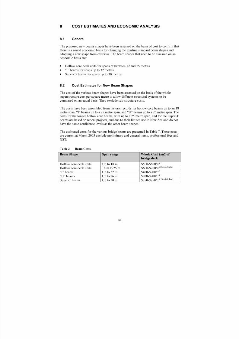
8/9/2019 Standard Bridge Beams
http://slidepdf.com/reader/full/standard-bridge-beams 52/67
52
8 COST ESTIMATES AND ECONOMIC ANALYSIS
8.1 General
The proposed new beams shapes have been assessed on the basis of cost to confirm thatthere is a sound economic basis for changing the existing standard beam shapes andadopting a new shape from overseas. The beam shapes that need to be assessed on aneconomic basis are:
• Hollow core deck units for spans of between 12 and 25 metres
• “I” beams for spans up to 32 metres
• Super-T/ beams for spans up to 30 metres
8.2 Cost Estimates for New Beam Shapes
The cost of the various beam shapes have been assessed on the basis of the wholesuperstructure cost per square metre to allow different structural systems to becompared on an equal basis. They exclude sub-structure costs.
The costs have been assembled from historic records for hollow core beams up to an 18metre span, “I” beams up to a 25 metre span, and “U” beams up to a 26 metre span. Thecosts for the longer hollow core beams, with up to a 25 metre span, and for the Super-T
beams are based on recent projects, and due to their limited use in New Zealand do nothave the same confidence levels as the other beam shapes.
The estimated costs for the various bridge beams are presented in Table 7. These costsare current at March 2003 exclude preliminary and general items, professional fees andGST.
Table 3 Beam Costs
Beam Shape Span range Whole Cost $/m2 of
bridge deck
Hollow core deck units Up to 18 m $500-$600/m2
Hollow core deck units 18 m to 25 m $600-$700/m2(limited data) “I” beams Up to 32 m $400-$900/m2
“U” beams Up to 26 m $700-$900/m2
Super-T beams Up to 30 m $750-$850/m2 (limited data)
8/9/2019 Standard Bridge Beams
http://slidepdf.com/reader/full/standard-bridge-beams 53/67
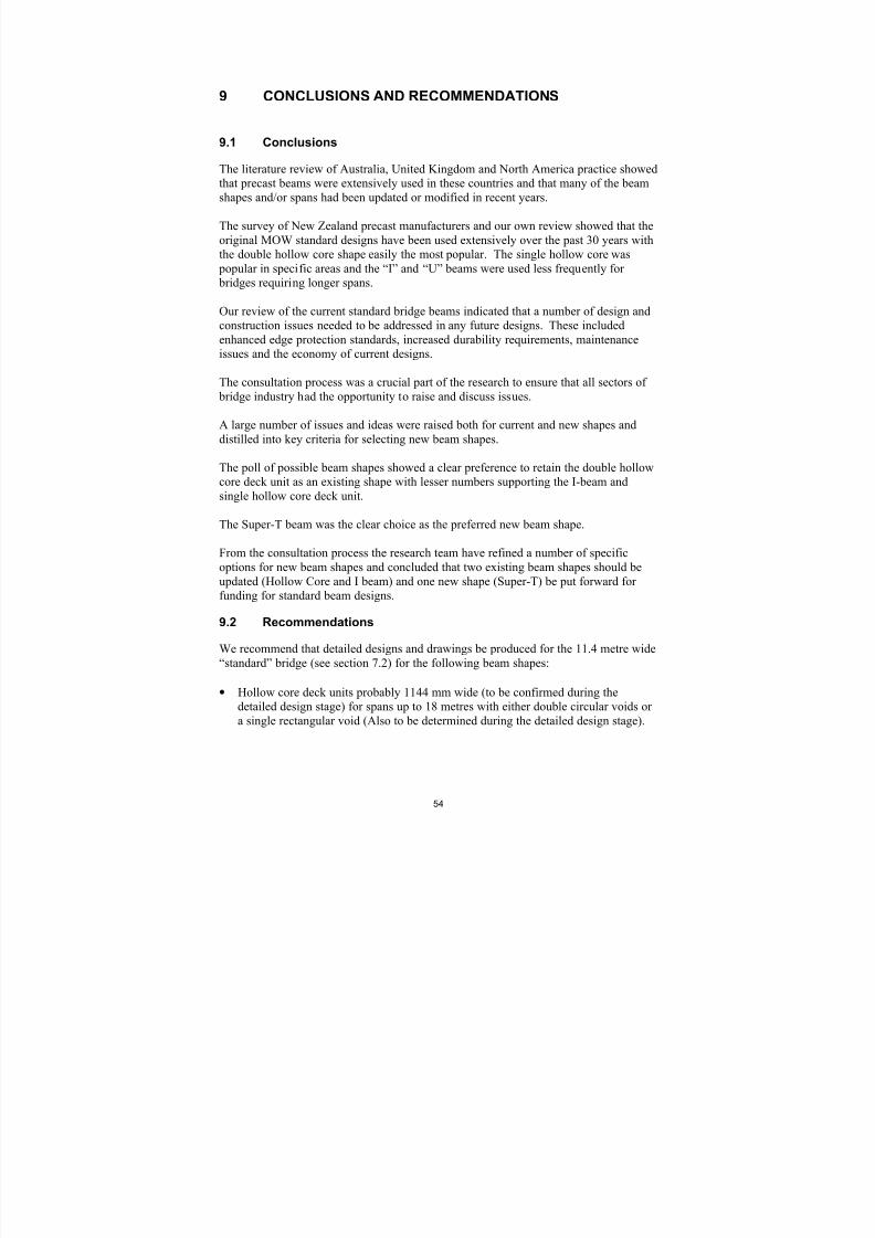
8/9/2019 Standard Bridge Beams
http://slidepdf.com/reader/full/standard-bridge-beams 54/67
54
9 CONCLUSIONS AND RECOMMENDATIONS
9.1 Conclusions
The literature review of Australia, United Kingdom and North America practice showedthat precast beams were extensively used in these countries and that many of the beamshapes and/or spans had been updated or modified in recent years.
The survey of New Zealand precast manufacturers and our own review showed that theoriginal MOW standard designs have been used extensively over the past 30 years withthe double hollow core shape easily the most popular. The single hollow core was
popular in specific areas and the “I” and “U” beams were used less frequently for bridges requiring longer spans.
Our review of the current standard bridge beams indicated that a number of design andconstruction issues needed to be addressed in any future designs. These includedenhanced edge protection standards, increased durability requirements, maintenanceissues and the economy of current designs.
The consultation process was a crucial part of the research to ensure that all sectors of bridge industry had the opportunity to raise and discuss issues.
A large number of issues and ideas were raised both for current and new shapes anddistilled into key criteria for selecting new beam shapes.
The poll of possible beam shapes showed a clear preference to retain the double hollowcore deck unit as an existing shape with lesser numbers supporting the I-beam andsingle hollow core deck unit.
The Super-T beam was the clear choice as the preferred new beam shape.
From the consultation process the research team have refined a number of specificoptions for new beam shapes and concluded that two existing beam shapes should beupdated (Hollow Core and I beam) and one new shape (Super-T) be put forward forfunding for standard beam designs.
9.2 Recommendations
We recommend that detailed designs and drawings be produced for the 11.4 metre wide“standard” bridge (see section 7.2) for the following beam shapes:
• Hollow core deck units probably 1144 mm wide (to be confirmed during thedetailed design stage) for spans up to 18 metres with either double circular voids ora single rectangular void (Also to be determined during the detailed design stage).

8/9/2019 Standard Bridge Beams
http://slidepdf.com/reader/full/standard-bridge-beams 55/67
55
• Hollow core deck unit for spans up to 25 metres, with void shape to be determinedduring the detailed design stage
• Existing “I” beams for spans up to 32 metres, updated for changes to designstandards
• Super-T beam for spans up to 30 metres.
We also recommend that the existing single core deck units and “U” beams are notupdated as new standard shapes. The “U” beam will be replaced by the new Super-T
beam, and the single core deck unit by the new hollow core deck unit.
These shapes are shown in Figure 10.
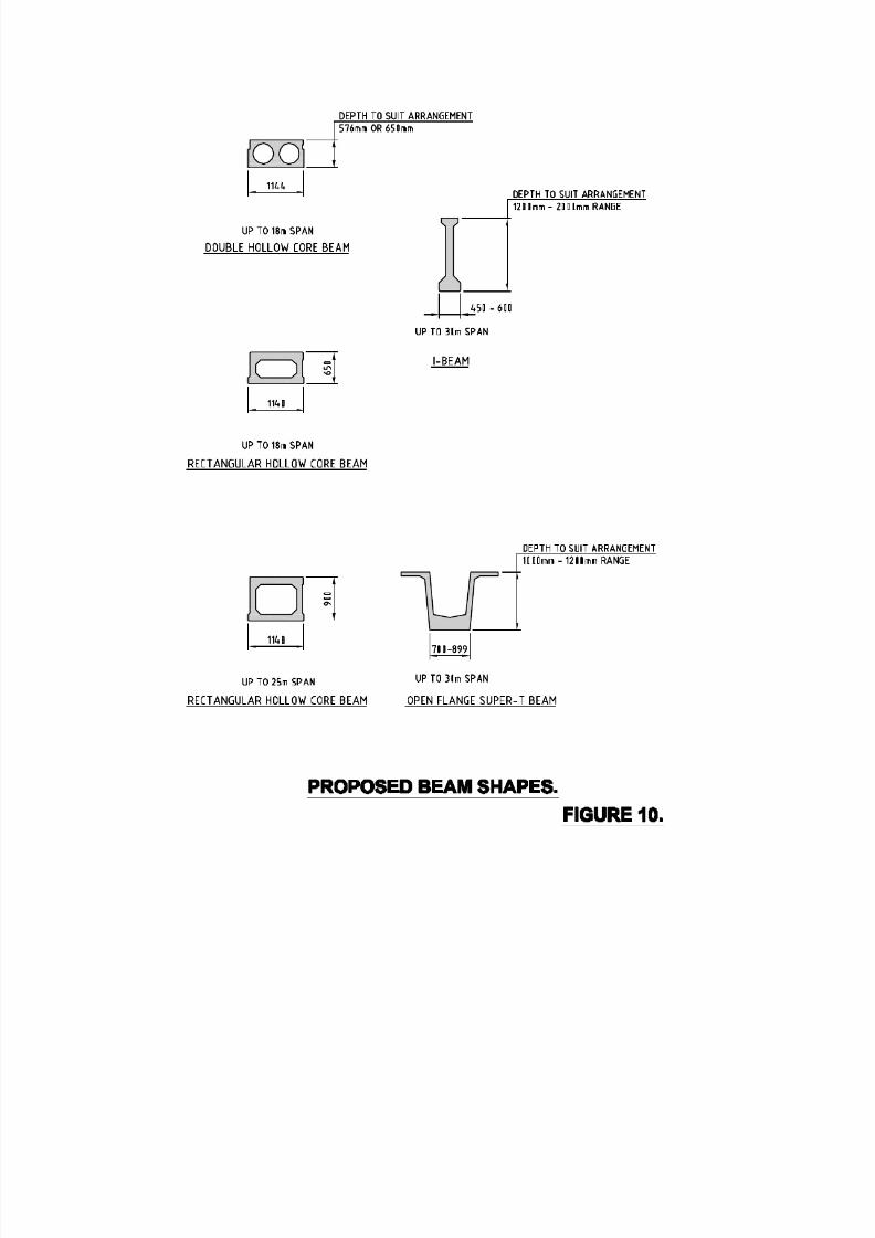
8/9/2019 Standard Bridge Beams
http://slidepdf.com/reader/full/standard-bridge-beams 56/67
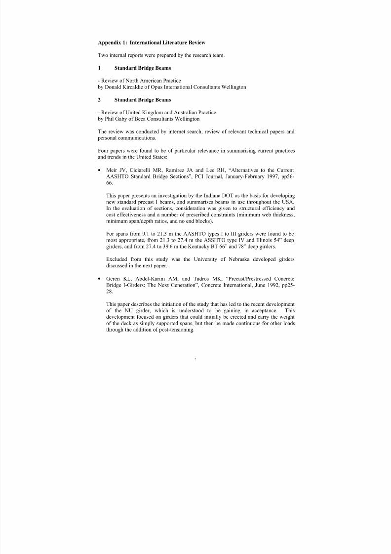
8/9/2019 Standard Bridge Beams
http://slidepdf.com/reader/full/standard-bridge-beams 57/67
1
Appendix 1: International Literature Review
Two internal reports were prepared by the research team.
1 Standard Bridge Beams
- Review of North American Practice by Donald Kircaldie of Opus International Consultants Wellington
2 Standard Bridge Beams
- Review of United Kingdom and Australian Practice by Phil Gaby of Beca Consultants Wellington
The review was conducted by internet search, review of relevant technical papers and
personal communications.
Four papers were found to be of particular relevance in summarising current practicesand trends in the United States:
• Meir JV, Ciciarelli MR, Ramirez JA and Lee RH, “Alternatives to the CurrentAASHTO Standard Bridge Sections”, PCI Journal, January-February 1997, pp56-66.
This paper presents an investigation by the Indiana DOT as the basis for developingnew standard precast I beams, and summarises beams in use throughout the USA.In the evaluation of sections, consideration was given to structural efficiency andcost effectiveness and a number of prescribed constraints (minimum web thickness,minimum span/depth ratios, and no end blocks).
For spans from 9.1 to 21.3 m the AASHTO types I to III girders were found to bemost appropriate, from 21.3 to 27.4 m the ASSHTO type IV and Illinois 54” deepgirders, and from 27.4 to 39.6 m the Kentucky BT 66” and 78” deep girders.
Excluded from this study was the University of Nebraska developed girdersdiscussed in the next paper.
• Geren KL, Abdel-Karim AM, and Tadros MK, “Precast/Prestressed ConcreteBridge I-Girders: The Next Generation”, Concrete International, June 1992, pp25-28.
This paper describes the initiation of the study that has led to the recent developmentof the NU girder, which is understood to be gaining in acceptance. Thisdevelopment focused on girders that could initially be erected and carry the weightof the deck as simply supported spans, but then be made continuous for other loadsthrough the addition of post-tensioning.

8/9/2019 Standard Bridge Beams
http://slidepdf.com/reader/full/standard-bridge-beams 58/67
2
• Waheed A, Delaurentiis N, and Hancock L, “Use of Long Span Concrete Girders(NU) in Alberta”, Proceedings of the Sixth International Conference on Short andMedium Span Bridges, Vancouver, Canada, 2002.
This paper provides a description of the NU girders, including two case studies oftheir use, and description of their design and fabrication features.
• Seguirant S, “New Deep WSDOT Standard Sections Extend Spans of PrestressedConcrete Girders”, PCI Journal, July/August 1998, pp92-119.
This paper describes the development of new, deep, precast, prestressed concretegirder sections for the Washington State DOT. The girders can be used at widerspacings with fewer girder lines, in place of the previous standard beams used. Thesections are available in both single-piece, pretensioned, and multiple-piece post-
tensioned segmental versions. These sections represent a further development fromthe University of Nebraska’s NU girder series.
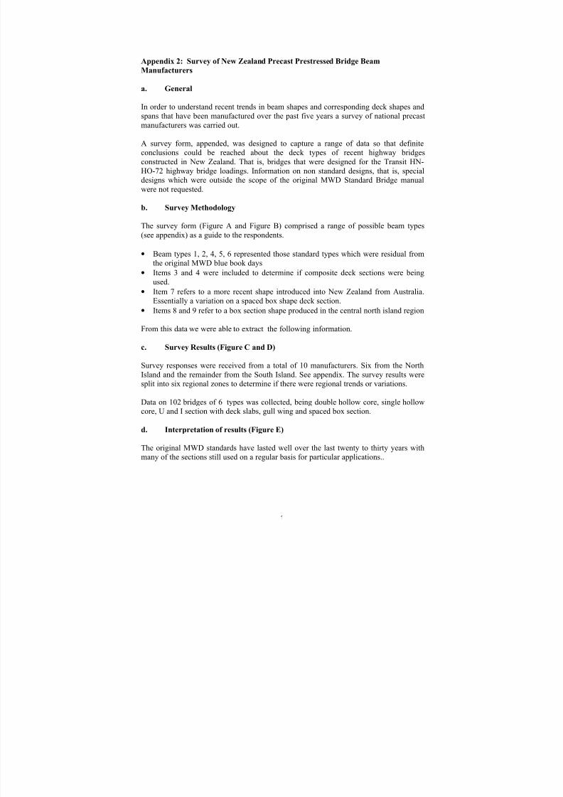
8/9/2019 Standard Bridge Beams
http://slidepdf.com/reader/full/standard-bridge-beams 59/67
1
Appendix 2: Survey of New Zealand Precast Prestressed Bridge Beam
Manufacturers
a. General
In order to understand recent trends in beam shapes and corresponding deck shapes andspans that have been manufactured over the past five years a survey of national precastmanufacturers was carried out.
A survey form, appended, was designed to capture a range of data so that definiteconclusions could be reached about the deck types of recent highway bridgesconstructed in New Zealand. That is, bridges that were designed for the Transit HN-HO-72 highway bridge loadings. Information on non standard designs, that is, specialdesigns which were outside the scope of the original MWD Standard Bridge manualwere not requested.
b. Survey Methodology
The survey form (Figure A and Figure B) comprised a range of possible beam types(see appendix) as a guide to the respondents.
• Beam types 1, 2, 4, 5, 6 represented those standard types which were residual fromthe original MWD blue book days
• Items 3 and 4 were included to determine if composite deck sections were beingused.
•
Item 7 refers to a more recent shape introduced into New Zealand from Australia.Essentially a variation on a spaced box shape deck section.
• Items 8 and 9 refer to a box section shape produced in the central north island region
From this data we were able to extract the following information.
c. Survey Results (Figure C and D)
Survey responses were received from a total of 10 manufacturers. Six from the NorthIsland and the remainder from the South Island. See appendix. The survey results weresplit into six regional zones to determine if there were regional trends or variations.
Data on 102 bridges of 6 types was collected, being double hollow core, single hollowcore, U and I section with deck slabs, gull wing and spaced box section.
d. Interpretation of results (Figure E)
The original MWD standards have lasted well over the last twenty to thirty years withmany of the sections still used on a regular basis for particular applications..

8/9/2019 Standard Bridge Beams
http://slidepdf.com/reader/full/standard-bridge-beams 60/67
2
• The majority of responses indicated the popularity of Double HC bridge decksthroughout all regions.
• Single hollowcore was popular with the north of the south island and in the centralnorth island.
• The I and U sections were used for bridges requiring longer spans, but have beenused to a lesser extent than the twin hollow core
• A variation on the popular Double HC bridge decks is the single cell box sectionshape, which was used extensively on Route PJK in Tauranga.
Span/depth ratios:
A comparison of the span/depth ratios against other authorities recommendations wascarried out to see if there were patterns of structural consistency. While the I, Gull wingand box section show a reasonably good comparison the Double Hollow core unitsshow a wide variation.
The survey indicates the popularity of the Double Hollow Core unit as a standard stockunit which has provided highway bridge design flexibility and economic benefits duringthe past thirty years.

8/9/2019 Standard Bridge Beams
http://slidepdf.com/reader/full/standard-bridge-beams 61/67
3
DATA CAPTURE SURVEY FORM – PRECAST BRIDGES MANUFACTURED in NZ
For the period 1997 to 2002
COMPANY NAME: _________________________LOCATION:_____________________
Figure A
1 2 3 4 5 6A 6B 7 8 Item Contract Name
and
Bridge location
Date
produced
(mth., yr)
Number
of
Spans
Deck
Spans
m
Number
of
Lanes
or Deck
width
m
Product
Type
No.
Prod.
Type
depth
x
width
mm x
mm
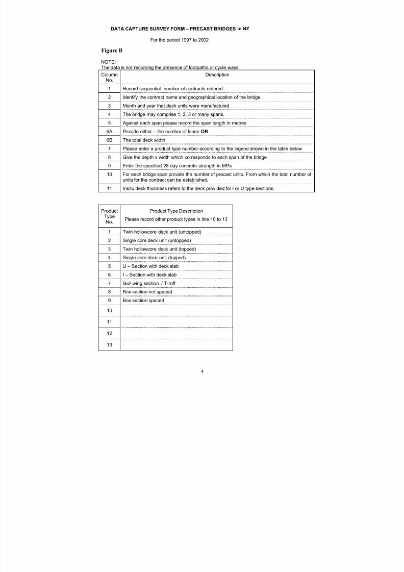
8/9/2019 Standard Bridge Beams
http://slidepdf.com/reader/full/standard-bridge-beams 62/67
4
DATA CAPTURE SURVEY FORM – PRECAST BRIDGES in NZ
For the period 1997 to 2002
Figure B
NOTE:The data is not recording the presence of footpaths or cycle ways
ColumnNo.
Description
1 Record sequential number of contracts entered
2 Identify the contract name and geographical location of the bridge
3 Month and year that deck units were manufactured
4 The bridge may comprise 1, 2, 3 or many spans.
5 Against each span please record the span length in metres
6A Provide either – the number of lanes OR
6B The total deck width7 Please enter a product type number according to the legend shown in the table below
8 Give the depth x width which corresponds to each span of the bridge
9 Enter the specified 28 day concrete strength in MPa
10 For each bridge span provide the number of precast units. From which the total number ofunits for the contract can be established.
11 Insitu deck thickness refers to the deck provided for I or U type sections.
ProductTypeNo.
Product Type DescriptionPlease record other product types in line 10 to 13
1 Twin hollowcore deck unit (untopped)
2 Single core deck unit (untopped)
3 Twin hollowcore deck unit (topped)
4 Single core deck unit (topped)
5 U – Section with deck slab
6 I – Section with deck slab
7 Gull wing section / T-roff
8 Box section not spaced
9 Box section spaced
10
11
12
13

8/9/2019 Standard Bridge Beams
http://slidepdf.com/reader/full/standard-bridge-beams 63/67

8/9/2019 Standard Bridge Beams
http://slidepdf.com/reader/full/standard-bridge-beams 64/67
PRECAST PRECAST BRIDGE DECKSNEW ZEALAND PRECASTER SURVEY
September 2002
6
Figure D
Bridges B E A M T Y P E S
by 1 2 3 4 5 6
Zone Description Zone DHC SHC DHC SHC U-Sectn + I-Sectn + topped topped deck slab deck slab
1 Otago-Southland 7 6 1
2 Nth. Sth. Island 26 18 6 2
3 Wgtn.+Manawatu 6 4 1
4 Central Nth. Island 48 35 6 2 2
5 Auckland 2 1 1
6 Nth. Auckland 13 10 2 1
102 73 14 0 0 5 6
Span/Depth Ratios: 13 to 42 25 to 31 0 0.00 20 to 26 14 to 23
Comparison recommendations 24 to 26 22 to 24
for span/depth taken from T.Y. Lin

8/9/2019 Standard Bridge Beams
http://slidepdf.com/reader/full/standard-bridge-beams 65/67
PRECAST PRECAST BRIDGE DECKSNEW ZEALAND PRECASTER SURVEY
September 2002
7
Figure E
Item PRODUCT Span/ Topping Deck Units No. Total Conc
Type Span Depth Depth Width Thickness Width per of Units Region f'cNo. m mm Ratio mm mm m Span Spans No. MPa
1 1 8.20 458 18 914 0 4.57 5 1 5 Wgtn 40
2 5 22.00 1100 20 874 150 8.74 10 5 50 Auck 40
3 1 12.20 458 27 914 0 12.80 14 1 14 Central N. I. 40
4 1 12.20 575 21 1144 0 9.15 8 1 8 Central N. I. 40
5 1 14.20 575 25 1144 0 10.30 9 2 18 Central N. I. 40
6 1 11.75 458 26 914 0 9.14 10 2 20 Central N. I. 40
7 1 10.20 458 22 914 0 8.23 9 1 9 Central N. I. 40
8 6 20.40 1500 14 450 150 10.00 4 3 12 Wgtn 40
9 1 12.20 575 21 1144 0 6.86 6 3 18 Central N. I. 40
10 1 18.20 575 32 1144 0 9.15 8 3 24 Central N. I. 40
11 1 16.20 575 28 1144 0 10.30 9 1 9 Central N. I. 40
12 1 18.20 650 28 1144 0 9.15 8 1 8 Central N. I. 40
13 1 18.00 650 28 1144 0 9.15 8 5 40 Wgtn 40
14 1 16.50 575 29 1144 0 5.72 5 1 5 Wgtn 40
15 1 12.00 458 26 914 0 10.97 12 2 24 Central N. I. 40
16 1 14.00 575 24 1144 0 11.44 10 2 20 Central N. I. 40
17 1 16.00 575 28 1144 0 11.44 10 2 20 Central N. I. 40
18 1 12.00 576 21 1144 0 0 5 16 80 Nth.Cn.Sth.I 40
19 6 23.00 1200 19 - 0 0 4 4 16 Nth.Cn.Sth.I 40
20 1 12.00 576 21 1144 0 0 5 3 15 Nth.Cn.Sth.I 40
21 1 15.00 576 26 1144 0 0 5 6 30 Nth.Cn.Sth.I 40
22 1 16.00 576 28 1144 0 0 4 1 4 Nth.Cn.Sth.I 40
23 1 18.00 576 31 1144 0 0 4 1 4 Nth.Cn.Sth.I 40
24 6 24.00 1600 15 - 200 0 5 3 15 North Shore 50
25 6 20.40 1500 14 - 200 0 4 4 16 Nth.Cn.Sth.I 40
26 1 6.20 458 14 914 0 0 6 4 24 Nth.Cn.Sth.I 40
11.20 576 19 1144 0 0 9 4 36 40
11.60 576 20 1144 0 0 6 4 24 40
27 1 8.00 458 17 914 0 0 2 11 22 Nth.Cn.Sth.I 40
6.00 458 13 0 0 6 3 18 40
28 1 9.60 458 21 914 0 0 6 5 30 Nth.Cn.Sth.I 40
29 1 17.50 650 27 1144 0 0.00 10 4 40 Otago/Sth 40
30 1 14.20 576 25 1144 0 0.00 20 1 20 Otago/Sth 4031 1 16.20 576 28 1144 0 0.00 20 1 20 Otago/Sth 40
32 5 20.40 1000 20 500 190 0.00 19 1 19 Otago/Sth 40
33 1 18.20 650 28 1144 0 0.00 3 1 3 Otago/Sth 40
34 1 10.20 458 22 914 0 0.00 10 1 10 Otago/Sth 40
35 1 16.12 576 28 1144 0 8.00 7 1 7 Nth.Auck 55
36 1 16.37 576 28 1144 0 4.57 4 1 4 Central N. I. 40
37 1 18.30 650 28 1144 0 4.57 4 1 4 Central N. I. 45
38 1 12.60 458 28 915 0 10.98 12 1 12 Nth.Auck 40
39 1 18.20 650 28 1144 0 4.50 4 1 4 Nth.Auck 40
40 1 8.00 458 17 915 0 4.57 5 1 5 Nth.Auck 40
41 1 12.20 458 27 915 0 9.15 10 1 10 Nth.Auck 40
42 1 16.00 576 28 1144 0 24.00 21 2 42 Nth.Auck 40
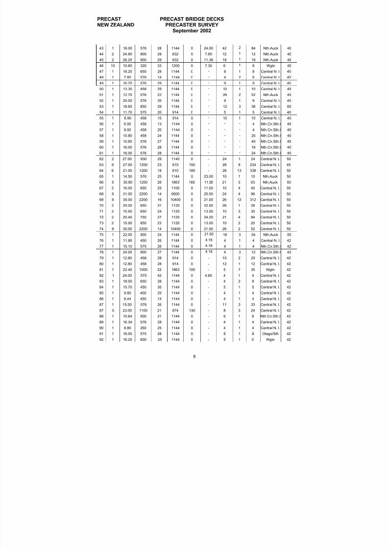
8/9/2019 Standard Bridge Beams
http://slidepdf.com/reader/full/standard-bridge-beams 66/67
PRECAST PRECAST BRIDGE DECKSNEW ZEALAND PRECASTER SURVEY
September 2002
8
43 1 16.00 576 28 1144 0 24.00 42 2 84 Nth.Auck 40
44 2 24.80 900 28 632 0 7.65 12 1 12 Nth.Auck 40
45 2 26.20 900 29 632 0 11.38 18 1 18 Nth.Auck 40
46 10 10.60 320 33 1200 0 7.30 6 1 6 Wgtn 40
47 1 18.20 650 28 1144 0 - 8 1 8 Central N. I. 40
48 1 7.80 576 14 1144 0 - 4 2 8 Central N. I. 45
49 1 16.70 576 29 1144 0 - 9 1 9 Central N. I. 40
50 1 13.30 458 29 1144 0 - 10 1 10 Central N. I. 40
51 1 12.70 576 22 1144 0 - 26 2 52 Nth.Auck 45
52 1 20.00 576 35 1144 0 - 9 1 9 Central N. I. 45
53 1 18.65 650 29 1144 0 - 12 3 36 Central N. I. 60
54 1 11.70 575 20 914 0 - 5 1 5 Central N. I. 40
55 1 6.90 458 15 914 0 - 10 1 10 Central N. I. 40
56 1 6.00 458 13 1144 0 - - - 4 Nth.Cn.Sth.I 40
57 1 9.00 458 20 1144 0 - - - 4 Nth.Cn.Sth.I 40
58 1 10.80 458 24 1144 0 - - - 20 Nth.Cn.Sth.I 40
59 1 15.60 576 27 1144 0 - - - 40 Nth.Cn.Sth.I 40
60 1 16.00 576 28 1144 0 - - - 16 Nth.Cn.Sth.I 40
61 1 16.00 576 28 1144 0 - - - 24 Nth.Cn.Sth.I 40
62 2 27.00 930 29 1140 0 - 24 1 24 Central N. I. 50
63 6 27.00 1200 23 610 150 - 26 9 234 Central N. I. 45
64 6 21.00 1200 18 610 180 - 26 13 338 Central N. I. 50
65 1 14.50 576 25 1144 0 23.00 10 1 10 Nth.Auck 50
66 5 30.80 1200 26 1863 160 11.50 21 3 63 Nth.Auck 50
67 2 16.00 650 25 1100 0 11.00 10 4 40 Central N. I. 50
68 9 31.00 2200 14 9500 0 20.00 24 4 96 Central N. I. 50
69 9 35.00 2200 16 10400 0 21.00 26 12 312 Central N. I. 50
70 2 20.00 650 31 1120 0 32.00 26 1 26 Central N. I. 50
71 2 15.50 650 24 1120 0 13.00 10 3 30 Central N. I. 50
72 2 20.40 750 27 1120 0 24.20 21 4 84 Central N. I. 50
73 2 15.00 650 23 1120 0 13.00 10 2 20 Central N. I. 50
74 9 30.00 2200 14 10400 0 21.00 26 2 52 Central N. I. 50
75 1 22.00 900 24 1144 0 21.00 18 3 54 Nth.Auck 50
76 1 11.90 450 26 1144 0 4.16 4 1 4 Central N. I. 42
77 1 15.10 575 26 1144 0 4.16 4 1 4 Nth.Cn.Sth.I 42
78 1 24.00 900 27 1144 0 4.16 4 3 12 Nth.Cn.Sth.I 42
79 1 12.80 458 28 914 0 - 10 2 20 Central N. I. 42
80 1 12.80 458 28 914 0 - 12 1 12 Central N. I. 42
81 7 22.40 1000 22 1863 100 - 5 7 35 Wgtn 4282 1 24.00 575 42 1144 0 4.60 4 1 4 Central N. I. 42
83 1 18.00 650 28 1144 0 - 4 2 8 Central N. I. 42
84 1 15.70 450 35 1144 0 - 5 1 5 Central N. I. 42
85 1 9.80 400 25 1144 0 - 4 1 4 Central N. I. 42
86 1 6.44 450 14 1144 0 - 4 1 4 Central N. I. 42
87 1 15.00 576 26 1144 0 - 11 3 33 Central N. I. 42
87 5 23.00 1100 21 874 130 - 8 3 24 Central N. I. 42
88 1 10.64 500 21 1144 0 - 6 1 6 Nth.Cn.Sth.I 42
89 1 16.34 576 28 1144 0 - 4 1 4 Central N. I. 42
90 1 8.80 350 25 1144 0 - 4 1 4 Central N. I. 42
91 1 16.00 575 28 1144 0 - 8 1 8 Otago/Sth 42
92 1 16.20 650 25 1144 0 - 5 1 5 Wgtn 42

8/9/2019 Standard Bridge Beams
http://slidepdf.com/reader/full/standard-bridge-beams 67/67
PRECAST PRECAST BRIDGE DECKSNEW ZEALAND PRECASTER SURVEY
September 2002
93 1 16.10 576 28 1144 0 - 10 2 20 Central N. I. 42
94 1 18.00 650 28 1144 0 - 8 9 72 Central N. I. 42
95 2 18.20 650 28 650 0 - 4 6 24 Nth.Cn.Sth.I 40
96 2 18.00 650 28 650 0 - 12 2 24 Nth.Cn.Sth.I 40
97 2 22.00 800 28 750 0 - 12 1 12 Nth.Cn.Sth.I 40
98 2 22.00 800 28 750 0 - 12 1 12 Nth.Cn.Sth.I 40
99 1 14.00 585 24 1144 0 - 14 1 14 Nth.Cn.Sth.I 40
100 2 16.50 650 25 650 0 - 6 2 12 Nth.Cn.Sth.I 40
101 2 16.50 650 25 650 0 - 7 1 7 Nth.Cn.Sth.I 40