Embed Size (px)
DESCRIPTION
vf
Citation preview

SCHOOLS STANDARD AIR CONDITIONING
SPECIFICATION
80 GEORGE STREET, BRISBANE QLD 4000
© Copyright - The State of Queensland, ( Project Services 2010 )
20 October 2010
(Version 2)

Schools Standard Air Conditioning 2 Project Services Specification (Version 2)
THIS PAGE INTENTIONALLY LEFT BLANK

TABLE OF CONTENTS
Schools Standard Air Conditioning 3 Project Services Specification (Version 2)
TABLE OF CONTENTS SECTION PAGE Table of Contents ............................................................................................................................................................. 3 1. Preliminaries ...................................................................................................................................................................... 5 2. Scope ................................................................................................................................................................................ 21 3. Mechanical Services ....................................................................................................................................................... 25 4. Electrical Services ........................................................................................................................................................... 65 5. Demolition .............................................................................................................................................................101 6. Operation and Maintenance Manuals ........................................................................................................................... 107

TABLE OF CONTENTS
Schools Standard Air Conditioning 4 Project Services Specification (Version 2)
THIS PAGE INTENTIONALLY LEFT BLANK

SECTION 1 PRELIMINARIES
Schools Standard Air Conditioning Project Services Specification (Version 2) 5
SECTION 1 PRELIMINARIES
1 GENERAL
1.1 GENERAL General conditions To D.P.W. Minor Works Conditions of Contract.
Publicity Do not issue information concerning the project for publication in the media without prior written approval of the Head of Facility (School Principal). Refer enquiries from the media concerning the project to the Head of Facility.
General description of the works Nothing in this clause shall limit, modify or alter the extent or description of the Works as set out in detail elsewhere in the Contract documents. Subject to the foregoing, the Works generally comprise the design, documentation, statutory approval, certification, demolition, construction, commissioning and completion of the air conditioning installation and electrical upgrade project including all works in association.
1.2 DEFINITIONS General The Principal under the building contract is a contractual description of one of the parties to the contract. To differentiate this from the School Principal in this document we have re-defined the Principal of the school.
Unless the context otherwise requires, the following definitions apply:
- Principal: means the Principal under the contract, as defined in General Conditions of Contract,
- Head of Facility: means the school’s chief executive, generally referred to as “School Principal”.
1.3 CROSS REFERENCE Requirement This Preliminary Section is to be read in conjunction with the following Specification Sections to ascertain full extent of Preliminaries:
- Section 3 Mechanical Services Clause 1. General
- Section 4 Electrical Services Clause 1. General
1.4 DOCUMENTS Contract documents Items: The contract documents comprise all documents described in the Letter of Acceptance of Tender, and include:
- Minor Works Conditions of Contract (with design responsibility), as issued by the Department of Public Works,
- this Specification,
- the accepted Tender Form and accompanying information,
- any other drawings or documents issued in accordance with the Contract during the course of the contract.
Classified documents Do not disclose to third parties contract documents marked with a classification such as "Restricted", "Confidential" or "Secret", except with prior written approval of the Principal and subject to conditions imposed.
Contractor's documents Time: Where the Contract requires the Contractor to supply documents such as shop drawings, technical schedules or other written information, supply them within 5 weeks of receipt of Letter of Acceptance for examination, and revision if necessary, to occur before they are required for use.
Work as executed drawings Number: Where work as executed drawings are called for in the Contract, prepare drawings showing the "as installed" locations as specified in the General Requirements section. Where operation and maintenance
SECTION 1 PRELIMINARIES
Schools Standard Air Conditioning Project Services Specification (Version 2) 6
manuals are called for in the Contract, include in each manual a copy of each work as executed drawing relevant to that portion of the Works, otherwise submit two copies of each drawing.
2 DESIGN AND DOCUMENTATION
2.1 PREPARATION OF CONSTRUCTION DOCUMENTS General The Contractor is responsible for construction design, documentation and certification of the works required by the Contract. Consult with the Head of Facility to ensure that the Construction Documents reflect the Head of Facility’s requirements.
The Contractor must comply with the specific design requirements specified in:
- Section 2 Scope
- Section 3 Mechanical Services
- and Section 4 Electrical Services.
Design Drawings Design Drawings shall be provided to the Principal prior to commencement of works, the drawings shall include:
- Mechanical services drawings in accordance with Section 3 Mechanical Services, Clause 2.Design and Documentation.
- Electrical services drawings in accordance with Section 4 - Electrical Services, Clause 1.5 Design and Documentation.
- Shop drawings.
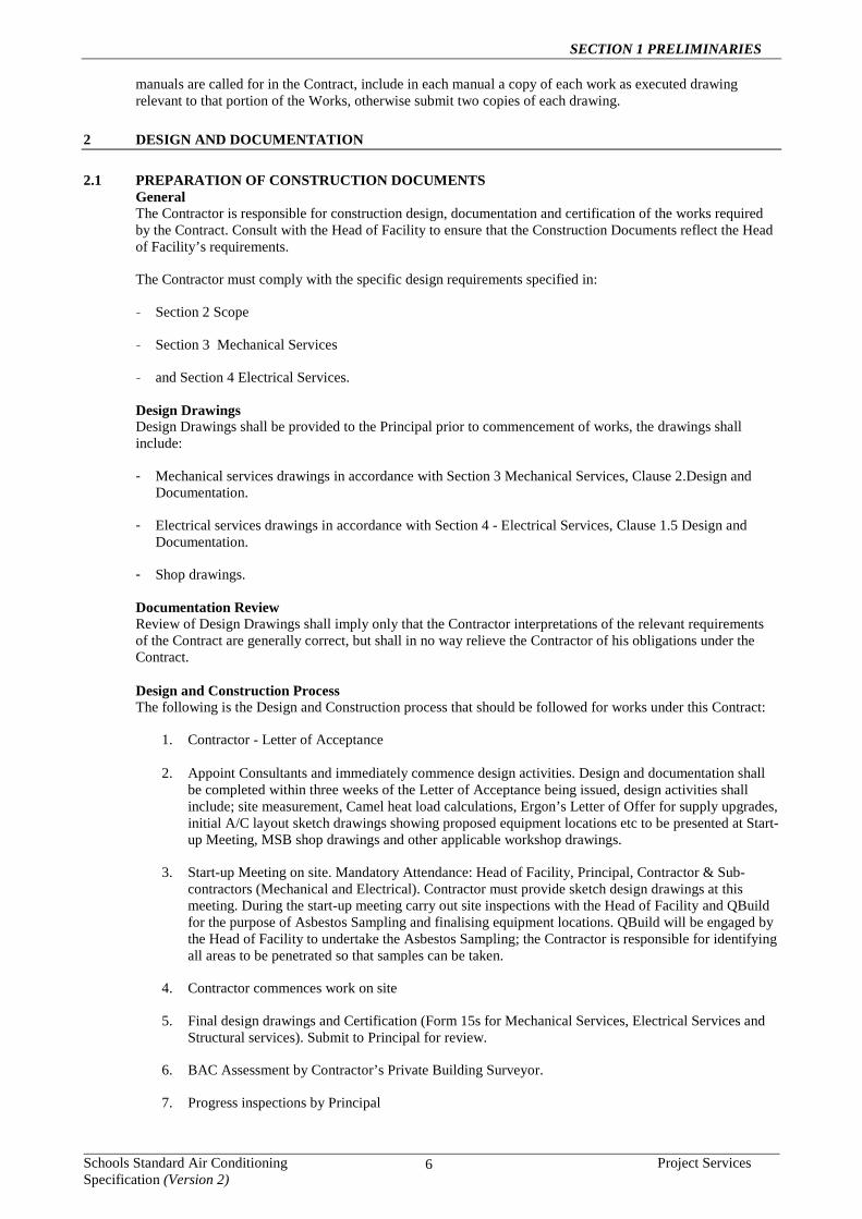
Documentation Review Review of Design Drawings shall imply only that the Contractor interpretations of the relevant requirements of the Contract are generally correct, but shall in no way relieve the Contractor of his obligations under the Contract. Design and Construction Process The following is the Design and Construction process that should be followed for works under this Contract:
1. Contractor - Letter of Acceptance
2. Appoint Consultants and immediately commence design activities. Design and documentation shall be completed within three weeks of the Letter of Acceptance being issued, design activities shall include; site measurement, Camel heat load calculations, Ergon’s Letter of Offer for supply upgrades, initial A/C layout sketch drawings showing proposed equipment locations etc to be presented at Start-up Meeting, MSB shop drawings and other applicable workshop drawings.
3. Start-up Meeting on site. Mandatory Attendance: Head of Facility, Principal, Contractor & Sub-contractors (Mechanical and Electrical). Contractor must provide sketch design drawings at this meeting. During the start-up meeting carry out site inspections with the Head of Facility and QBuild for the purpose of Asbestos Sampling and finalising equipment locations. QBuild will be engaged by the Head of Facility to undertake the Asbestos Sampling; the Contractor is responsible for identifying all areas to be penetrated so that samples can be taken.
4. Contractor commences work on site
5. Final design drawings and Certification (Form 15s for Mechanical Services, Electrical Services and Structural services). Submit to Principal for review.
6. BAC Assessment by Contractor’s Private Building Surveyor.
7. Progress inspections by Principal

SECTION 1 PRELIMINARIES
Schools Standard Air Conditioning Project Services Specification (Version 2) 7
8. Manuals & certification in accordance with Section 6 operation and Maintenance Manuals.
9. Contractor conducts training on use of Air Conditioning equipment with user groups.
10. Practical Completion.
11. Defects and Liability Period including service and maintenance obligations.
2.2 APPOINTMENT OF CONSULTANTS The Contractor is required to engage a team of Design Consultants (under the supervision of the Contractor) sufficient to produce the full Construction Design and Documentation and meet the certification requirements.
The consultant team shall consist of the following consultants as a minimum:-
- Mechanical Engineer
- Electrical Engineer
- Structural Engineer
2.3 INSURANCES Independent Professional Consultants engaged by the Contractor (Contractor’s Certifying Consultants) shall maintain the following insurances:- - Public Liability in the amount shown in the Conditions of Contract Annexure Part A, and
- Professional Indemnity in the amount of $2,000,000.
2.4 INSPECTIONS No inspections carried out and certified by Contractor’s Certifying Consultants shall prejudice, remove or extinguish the right of the Principal to inspect, reject, certify and approve any element or part of the works.
3 COMPLIANCE WITH STATUTORY REQUIREMENTS
3.1 GENERAL The Contractor is to comply with statutory requirements in respect of the Works and pay any statutory fees
and charges in respect of the Works.
Without limiting the Contractor’s obligations under other paragraphs the Contractor is to:
- make all applications for approvals and give all notices required to comply with statutory requirements;
- advise the Principal in writing of the proposed application or notice two (2) days before making the application;
- when requested by the Principal, provide a copy of any documents, records or other information used or relied upon to prepare the application or notice;
- inform the Principal in writing of the requirements or conditions proposed by any authority in relation to the giving of an approval or consent and obtain the written permission of the Principal before agreeing to those requirements and conditions; and
- inform the Principal in writing of the time, date and location of any meeting between the Contractor and any authority in sufficient time to enable the Principal and the Head of Facility to arrange representation at the meeting.
If, in the Contractor’s opinion, any provision of requirement of the Contract is at variance with statutory requirements or the requirements of an authority the Contractor is to immediately notify the Principal in writing. The notification is to contain detailed particulars of:
- the provision or requirement which is at variance; and
- the amendment or modification of the provision or requirement recommended by the Contractor.
SECTION 1 PRELIMINARIES
Schools Standard Air Conditioning Project Services Specification (Version 2) 8
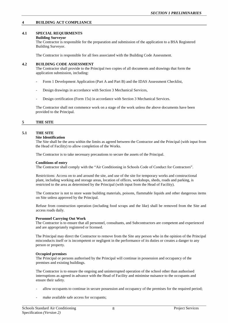
4 BUILDING ACT COMPLIANCE
4.1 SPECIAL REQUIRMENTS Building Surveyor The Contractor is responsible for the preparation and submission of the application to a BSA Registered Building Surveyor. The Contractor is responsible for all fees associated with the Building Code Assessment.
4.2 BUILDING CODE ASSESSMENT The Contractor shall provide to the Principal two copies of all documents and drawings that form the application submission, including:
- Form 1 Development Application (Part A and Part B) and the IDAS Assessment Checklist,
- Design drawings in accordance with Section 3 Mechanical Services,
- Design certification (Form 15s) in accordance with Section 3 Mechanical Services.
The Contractor shall not commence work on a stage of the work unless the above documents have been provided to the Principal.
5 THE SITE
5.1 THE SITE Site Identification The Site shall be the area within the limits as agreed between the Contractor and the Principal (with input from the Head of Facility) to allow completion of the Works.
The Contractor is to take necessary precautions to secure the assets of the Principal.
Conditions of entry The Contractor shall comply with the “Air Conditioning in Schools Code of Conduct for Contractors”.
Restrictions: Access on to and around the site, and use of the site for temporary works and constructional plant, including working and storage areas, location of offices, workshops, sheds, roads and parking, is restricted to the area as determined by the Principal (with input from the Head of Facility).
The Contractor is not to store waste building materials, poisons, flammable liquids and other dangerous items on Site unless approved by the Principal.
Refuse from construction operation (including food scraps and the like) shall be removed from the Site and access roads daily.
Personnel Carrying Out Work The Contractor is to ensure that all personnel, consultants, and Subcontractors are competent and experienced and are appropriately registered or licensed. The Principal may direct the Contractor to remove from the Site any person who in the opinion of the Principal misconducts itself or is incompetent or negligent in the performance of its duties or creates a danger to any person or property. Occupied premises The Principal or persons authorised by the Principal will continue in possession and occupancy of the premises and existing buildings.
The Contractor is to ensure the ongoing and uninterrupted operation of the school other than authorised interruptions as agreed in advance with the Head of Facility and minimise nuisance to the occupants and ensure their safety.
- allow occupants to continue in secure possession and occupancy of the premises for the required period;
- make available safe access for occupants;

SECTION 1 PRELIMINARIES
Schools Standard Air Conditioning Project Services Specification (Version 2) 9
- arrange work to minimize nuisance to occupants and ensure their safety; and
- protect occupants against weather, dust, dirt, water or other nuisance, by such means as temporary screens.
Proposals: Submit details of proposed methods.
Security System The Contractor is to arrange where approval is received to work outside nominated hours, with the building maintenance contractor to disarm and rearm appropriate access security devices as required to allow the Works to be completed. The Contractor is to also pay all service call out costs associated with these services at no additional cost to the Principal.
Protection of persons and property Protection of furniture, equipment & fittings: Provide protective plastic to cover all furniture, equipment and internal building fixtures and fittings whilst the works are being carried out.
Temporary works: Provide and maintain required barricades, guards, fencing (1.8m high wire mesh fence panels), shoring, temporary roadways, footpaths, signs, lighting, watching and traffic flagging.
Dust and noise control: Restrict dust caused by the Works to a minimum. Take all practicable precautions to minimise noise resulting from work under the Contract. Fit all construction equipment with noise suppressors and use so that noise is minimised.
Damage to services: Do not obstruct or damage roadways and footpaths, drains and watercourses and other existing services in use on or adjacent to the site. Determine the location of such services. Rectify immediately any obstruction or damage to such services and provide temporary services whilst repairs are carried out.
Damage to property: Do not interfere with or damage property which is to remain on or adjacent to the site, including adjoining property encroaching onto the site, and trees. Rectify immediately any interference or damage to such property.
Existing services Attend to existing services (such as drains, watercourses, public utility and other services) as follows:
- If the service is to be continued, repair, divert or relocate as required. If such a service crosses the line of a required trench, or will lose support when the trench is excavated, provide permanent support for the existing service.
- If the service is to be abandoned, cut and seal or disconnect, and make safe.
Proposals: Submit proposals for action to be taken with respect to existing services before starting this work. Minimize the number and duration of interruptions.
- Purpose of submission: For review.
The Contract sum shall be deemed to include the cost of dealing as above with existing services:
- the existence of which was ascertainable from the appropriate authority, or from visual inspection on or adjacent to the site, or from reviewing available drawings that are provided by the Principal upon request; or
- which are described in the Specification.
Notification: Notify the Principal immediately upon the discovery of services or obstructions not shown on the contract documents.
Interruption of Existing Electrical Services
The Contractor is to take all reasonable measures to identify location of services. As a minimum, the Contractor shall mark out all routes to be trenched and carry out a search using an electronic cable locator. All services located or marked on plans shall be identified and exposed using a Hydrovac machine to prevent damage.
The Contractor is to maintain existing services to all occupied areas and existing operational building

SECTION 1 PRELIMINARIES
Schools Standard Air Conditioning Project Services Specification (Version 2) 10
equipment throughout the Contract period except for approved interruption periods, which are to be kept to a minimum. The Contractor is to be held responsible for any damage suffered by the Principal, or to those users of the building within the precinct of the Site, due to an unauthorised interruption of a service.
The Contractor is to make an application to the Head of Facility for approval to interrupt an existing service five (5) working days prior to the intended date of the interruption. If the period for interruption applied for is unacceptable to the Head of Facility for a legitimate reason, the Contractor is to defer or advance the interruption period to suit. There shall be no grounds for claims for damages or extension of time due to the refusal.
In schools, where a power disruption will be longer than 2 hours, make arrangements with the school to deal with food stored in the canteen/tuckshop freezers/refrigerators, security systems, data servers and all other essential services. The Contractor shall provide a portable generator set to supply these items for power outages that exceed 2 hours duration.
If the security system is unable to be armed (i.e. without power) due to the work being carried out, allow for a security guard to patrol the site during nights, weekends and/or holidays, until the system is back in operation.
Dilapidation Record The Contractor is to before commencing work on the Site and within 20 days after the Date of Practical Completion:
- inspect all land, footpaths, roads, buildings or other structures which may be affected by the execution of the Works, in the company of the Principal (with input from Head of Facility);
- make a written and photographic record of existing visible defects; and
- lodge with the Principal a copy of each record of inspection showing the date of the inspection and signed on behalf of the Contractor and the Principal that the record of inspection is true and correct.
Precautions in Carrying Out Work Under the Contract Unless otherwise specified in the Contract, observe in the absence of statutory requirement to the contrary, the relevant current Australian Standard published by Standards Australia relating to storage, transport, use of materials, fire precautions in arc or flame cutting, flame heating, arc or gas welding operations, plant and equipment, work processes and safety precautions.
Explosive Power Tools Explosive power tools shall not be used, unless previously approved by the Principal
Protection of existing flora Protect from damage all trees and other plants which:
- are shown or specified to be retained, or
- need not be removed or damaged for construction operations.
Access roads Temporary roads: Provide any necessary temporary roadway as agreed with the Principal (with input from Head of Facility) and make good on completion.
5.2 PLANT Foreman's site office Provide a weather-tight site office for the use of the Foreman and Principal before major site operations are started and:
- provide reverse cycle air conditioning to the shed;
- install a desk of adequate size for reading drawings including chairs to seat a minimum of 2 people;
- provide fluorescent light over the desk and a double socket outlet at the desk;
- Builder shall have the ability to send and receive emails onsite;
- The Builder shall have a Digital camera and the ability to send and receive Jpeg photos from site;

SECTION 1 PRELIMINARIES
Schools Standard Air Conditioning Project Services Specification (Version 2) 11
- provide a Dry Chemical 4.5 kg fire extinguisher to AS 1846;
- pay charges for services;
- maintain the office in good order and in clean condition, with secure access, for duration of the work;
- obtain permission for removal; and
- remove on completion.
Protective clothing Safety helmets: Make available safety helmets for the use of visitors.
- Standard: To AS/NZS 1801, Type 1.
Number of helmets: 4
Temporary services Provide and maintain temporary services necessary for the execution of the work under the Contract. Install such services in accordance with the requirements of the relevant authorities. Pay charges in connection with the installation and use of such services. Make such services available to sub-contractors. On completion, disconnect and remove temporary services, and make good connection point and surrounds to match condition existing prior to connection.
Site amenities: Provide statutory and necessary amenities and sanitary facilities for workers and other persons lawfully upon the site and remove them on completion of the Works.
Temporary telephone: Provide a temporary telephone / data line in the Foreman's Office. Pay charges for installation, rental and calls. Pay charges for removal on completion.
Temporary barricades, hoardings and other risk control measures In accordance with the Workplace Health and Safety Regulation 1997, enclose all work and plant areas with temporary barricades (1.8m high mesh panel fencing), hoardings and other appropriate risk control measures. Incorporate lockable gates providing an equal level of risk control, where necessary. Remove on completion and make good all affected areas.
Use of existing services Existing services may be used as temporary services for the performance of the contract if approved by the Head of Facility.
Existing services schedule Service Conditions of use
Electricity Permitted to use services when required
Water Permitted to use services when required
Parking Principal's existing parking areas: Use only designated parking areas.
- Location: As directed by the Head of Facility.
6 ASBESTOS
6.1 CONSTRUCTION WORK Prohibition on use of various forms of asbestos Asbestos, in the following forms, must not be used, or re-used as a building material or product:
- crocidolite, amosite, fibrous anthophylite, tremolite, actinolite, or chrysotile.
Acceptable uses Notwithstanding the above prohibition on use, the above forms of asbestos may be used for the purposes of sampling, analysis, and maintenance in the minimum quantity necessary, and for removal, disposal,
SECTION 1 PRELIMINARIES
Schools Standard Air Conditioning Project Services Specification (Version 2) 12
encapsulation or enclosure as specified or directed.
Chrysotile products existing immediately before 31 December 2003 may also continue in use in their existing position, or be reinstalled in their existing position, or be used in a displayed artefact, unless otherwise specified.
6.2 ASBESTOS IN CHRYSOTILE FORM Prohibition on use of chrysotile asbestos in all forms From 31 December 2003, under the “National Model Regulations for the Control of Workplace Hazardous Substances”, chrysotile asbestos (“white asbestos”) cannot be imported into Australia, nor used or sold in any new product in Australia. Relevant products may include brake pads, brake friction products, gaskets and non-sag adhesives for the building industry.
Ensure that chrysotile asbestos in not included in any new or relocated materials or products to be incorporated into the Works.
6.3 ASBESTOS-CONTAINING MATERIAL (ACM) Statutory responsibilities Peruse, and become familiar with, the Register of Asbestos-Containing Material (ACM) for the proposed Works, which identifies locations on site where asbestos-containing materials have been found and/or are presumed to exist.
A copy of the Register is held at the site, for information purposes only. The Principal does not warrant that all asbestos-containing materials on the site are included in the copy of the Register.
Make all necessary allowances relating to the presence of asbestos-containing materials and permitted work methods as specified here or identified in the Contractor’s Work Plan or as otherwise directed.
Comply with all requirements relating to access to locations identified with or presumed to contain asbestos-containing materials, including:
- Department of Education and Training procedures in regard to issuing of Work Area Access Permits.
- Workplace Health and Safety Act 1995 (Qld), subordinate and associated legislation, codes and notices.
- Workers Compensation and Rehabilitation Act 2003 (Qld), subordinate and associated legislation.
- Environmental Protection Act 1994 (Qld), subordinate and associated legislation.
- Safe Work Australia publications (as amended) issued by the Australian Government, National Occupational Health and Safety Commission (NOHSC):
. Code of Practice for the Management and Control of Asbestos in Workplaces (2nd edition)
. Code of Practice for the Safe Removal of Asbestos (2nd edition)
. Guidance Note on the Membrane Filter Method for Estimating Airborne Asbestos Fibres (2nd edition).
- Australian Code for the Transport of Dangerous Goods by Road and Rail (ADG Code) (7th edition).
- Plumbing and Drainage Act 2002 (Qld), subordinate and associated legislation, codes and notices.
Restrictions associated with presence of low-density asbestos-containing board (LDB) If a Register of ACM exists for the site, the Works shall not proceed until identified or presumed ACM has been sampled and tested by a suitably-qualified person appointed by the Principal (Principal’s Advisor) for possible presence of LDB. All costs associated with appointment of a Principal’s Advisor and sampling / testing for LDB shall be borne by the Principal. If LDB is confirmed on site, a competent person under the relevant NOHSC Codes of Practice (Contractor’s Competent Person) shall determine if the Works may be completed without disturbing LDB material.
If the Works can be completed without disturbance of LDB, the Contract may proceed subject to site-specific Work Plan / Work Area Access Permit requirements being met. Alternatively, if avoidance of LDB disturbance cannot be assured, the Contract shall not commence until LDB is removed from the site by an A-Class certified Asbestos Removal Contractor. All costs associated with removal of LDB and attendant

SECTION 1 PRELIMINARIES
Schools Standard Air Conditioning Project Services Specification (Version 2) 13
rescheduling of the Works shall be borne by the Principal.
Work Plan and Work Area Access Permit requirements If a Register of ACM exists for the site and LDB matters have been addressed, the Works shall not commence until the following steps are completed:
- A Contractor’s Competent Person is nominated by the Contractor to take responsibility for work methods and risk control measures to be employed on the site. The Contractor’s Competent Person shall be appropriately assessed / certified under relevant NOHSC Codes of Practice and corresponding legislation.
- The Contractor, Contractor’s Competent Person, Principal and Head of Facility shall carry out an inspection of the grounds and all buildings and other structures included in work under the Contract to determine the extent that the Works may disturb materials that are identified or presumed to be ACM.
- As part of this inspection, the Contractor shall examine and sign the Register of ACM and any other document forming part of the facility’s Asbestos Management Plan as evidence that the Register has been made available to the Contractor for information purposes. The inspection shall take place at the initial start-up meeting and be minuted by the Contractor.
- If building materials affected by the Works are identified as or presumed to be ACM, two copies of a site-specific draft Work Plan (i.e. work method statement appropriate to the identified or presumed hazards and in accordance with statutory requirements and NOHSC Codes of Practice for working with ACM) shall be submitted to the Principal at least 10 working days before it is proposed to commence any work in conjunction with ACM.
- The Principal will seek the services of a Principal’s Advisor (QBuild) in determining whether a Work Area Access Permit shall be issued on the basis of information contained in the draft Work Plan. If the Principal requires amendments made to the draft Work Plan, two copies of a final Work Plan shall be resubmitted to address the Principal’s requirements.
- A Work Area Access Permit shall be issued by the Principal and received by the Contractor.
Elimination of risk in working with ACM The site-specific Work Plan shall describe the work methods and control measures proposed to eliminate risk from possible contact with ACM during performance of the Works, including:
- detail of anticipated hazards (with particular attention to site-specific and job-specific hazards),
- listing of corresponding risks to workers and other persons on or about the site of the Works, and
- sufficient information prepared by the Contractor’s Competent Person on proposed control measures to be implemented to manage all risks from possible contact with ACM during the course of the Works.
Contractor’s responsibilities Conform to requirements of the Work Plan and Work Area Access Permit during performance of the Works. Areas affected by the Work Area Access Permit must be unoccupied and adequately locked and signed to prevent access by unauthorised persons. Treat any existing or uncovered materials suspected of containing asbestos as ACM. Adhere to statutory requirements and NOHSC Codes of Practice in all instances.
Advise the Principal and the Head of Facility when all work involving ACM is complete, and finalise the “close off” process associated with the Work Area Access Permit. Inspection by the Principal and cancellation of the Work Area Access Permit signifies the lifting of restricted access to the affected areas.
Ceiling and overhead spaces Access into ceiling and other overhead spaces shall be typically obtained after hours and no person shall work in or travel through a ceiling above occupied spaces. Comply with the facility’s Asbestos Management Plan procedures in regard to obtaining access to ceilings beneath ACM roof sheeting or with ACM ceiling lining. Any work in confined spaces may require special-purpose personal protective equipment (PPE) to be worn.
7 ADMINISTRATION
7.1 ADMINISTRATION Program of work
Tender submission: The Contractor shall provide a time program as part of the tender submission, indicating

SECTION 1 PRELIMINARIES
Schools Standard Air Conditioning Project Services Specification (Version 2) 14
all activities occurring during the time required for the execution of the work under the Contract, including design development, documentation, construction and commissioning activities as detailed in the Notice to Tenderers.
Construction program: The Contractor is to produce a time scale bar chart within three weeks of the date of the Letter of Acceptance.
The bar chart shall show all activities necessary for the completion of the design and the work. All restraints or dependencies shall be shown such that the critical path is shown.
Key dates shall be clearly shown against relevant activities. Each activity shall be identified by a description, which shall permit easy identification, by reference to a specific portion of the Work.
Note: the construction program shall identify each of the two separable Portions separately and identify activities within the various stages of design, construction and commissioning, having regard for the Order of Work as agreed upon with the Principal and the time for achieving Practical Completion as specified in the tender form.
Any review of or comments upon a program by the Principal will not:
a) relieve the Contractor from or alter its liabilities or obligations under the Contract, b) evidence or constitute a direction by the Principal to accelerate, disrupt, prolong or vary any, or all, of the
Contractor’s Activities; or
c) affect the time for performance of the Principal’s Contract obligations, including (without limitation) oblige the Principal to do anything earlier than is necessary to enable the Contractor to achieve Completion by the Date for Practical Completion.
Payment: The Principal may refuse payment upon any certificate until such bar charts have been provided.
UPDATING: Allow for providing a minimum number of 1 updates of the construction program during the Contract.
Requirement: The updating of the Construction Program shall meet the following requirements:
- all copies of the Construction Program and Time Analysis shall be updated as requested in writing by the Principal. Such updates shall be delivered to the Principal within seven working days of the request. The number and cost of updates actually provided will be adjusted against the provisional items above.
- for the purpose of this Contract:
"STATUS" is defined as: "accurately recording the status of the work based on the percentage of activities complete on the applicable program".
"UPDATING" is defined as: "correcting activity sequences and adding or deleting activities, where necessary, to produce a network and analysis clearly indicative of the current job status and the intended progress".
- the status of the works is to be reviewed at one month periods in conjunction with such representatives as may be nominated by the Principal.
- or notwithstanding such reviews, prepare a monthly status report for submission and review by the Principal at the project team meeting. The status report shall contain description of critical activities, current status, non-critical activities which durations have varied, contract completion date, program completion date, report on milestones to be achieved over the ensuing month and items critical to maintain the program original status.
- no changes of activity duration during the course of the works shall be made without agreement of the Principal.
- outstanding claims for extension of time shall not negate the Contractor's obligation to provide an updated program.
- in the event that the Contractor does not comply with the provisions relating to updating, the Principal

SECTION 1 PRELIMINARIES
Schools Standard Air Conditioning Project Services Specification (Version 2) 15
may arrange to have the default rectified by other persons at the Contractor's expense.
EXTENSIONS OF TIME: All extensions of time granted to the Contractor shall be incorporated in the construction program by adjustment of the program relative to current job situation at the update immediately following the granting of the extension.
Quality assurance REQUIREMENT: The minimum Quality Assurance System required is a Second or Third party Certified Quality Assurance System to AS/NZS ISO 9001 including design in the capability statement.
Provide, when requested:
- copy of Quality Certificate and Capability Statement.
Quality Plan: Within 21 days of Tender acceptance, provide a copy of the Project Quality Plan to the Principal.
Keep on the site an “up to date” Project Quality Plan, including:
- Procedures covering each Trade, Worksection or part of a Package,
- Inspection and Test Plans for each Trade, Worksection or part of a Package,
- When requested, making it available to the Head of Facility for review.
Hold and Witness Points: The Principal has no obligation in respect of Hold and Witness points other than those specified or required to ensure Building Act compliance.
Compliance audits: Compliance audits of the contractor's project-wide quality system may be carried out even where the contractor's quality system provides for regular corporate auditing by an independent assessing organization, accredited by Joint Accreditation System of Australia and New Zealand (JAS-ANZ) for the purposes of certification.
Retention of records: Retain quality records for at least 7 years from the date of the final certificate.
8 EXECUTION OF THE WORKS
8.1 EXECUTION OF THE WORKS The Principal has undertaken to notify the Building and Construction Industry (Portable Long Service Leave) Authority (“QLeave”) of the building and construction work described in the Contract documents, and to pay all fees required under the provisions of the Building and Construction Industry (Portable Long Service Leave) Act.
Notices to be given and fees to be paid: Give notice and pay fees in respect of all other statutory requirements e.g. for Local Authority on-site drainage inspections and comply with all relevant statutory requirements in accordance with the Contract conditions. Take responsibility as the Principal Contractor under the Work Place Health and Safety Act.
Building act compliance documents: the Principal shall furnish to the Contractor one set of Building Act compliance documents. Keep these on site as required by the Building Regulation 2006. Comply with and complete the detailed requirements of the Building Act compliance documents as a condition precedent to certification of Practical Completion of the Works.
Building inspections: Inspections are required in accordance with the requirements of Part 6 of the Building Regulation 2006. These inspections shall be conducted by a representative of the Department of Public Works.
It will be the Contractor's responsibility to liaise with the nominated inspector regarding:
- the type and nature of inspections required,
- the staging and timing of such inspections, and
- notification periods required prior to required inspections.

SECTION 1 PRELIMINARIES
Schools Standard Air Conditioning Project Services Specification (Version 2) 16
Existing work If the Works include alterations or additions to existing work, verify the dimensions of the existing work before proceeding and notify discrepancies as required by the Contract.
Joining up Carry out the joining of new work to existing work, and any consequent cutting away, in a manner appropriate to the materials, and make good to existing work.
Salvaged items Unless otherwise stated by the Head of Facility that he/she would like to keep possession of the salvaged item, and subject to the provisions of the Minor Works Contract Conditions, materials, plant, equipment or other things salvaged from the Works shall become the property of the Contractor and shall be removed by him from the site.
8.2 COMPLETION Final cleaning Before practical completion, clean throughout, including interior and exterior surfaces exposed to view. Vacuum carpeted and soft surfaces. Clean debris from the site, roofs, gutters, downpipes and drainage systems. Remove waste, surplus materials and rubbish.
Ease and adjust all moving parts, doors, windows, etc., ensure all bolts and screws are tight, and test all services are working, to the approval of the Head of Facility.
Carry out the work outlined below using labour skilled in the particular operation required and to the Head of Facility's satisfaction.
- Clean all windows, both inside and out on all faces.
- Remove all render and other spots on metal sashes, box sections and other surfaces.
- Dust all walls, ledges and projections, etc.
- Wash and clean fittings, mirrors, walls, sinks, etc.
- Clean all floors and wash concrete slab areas.
- Remove all paint spots from floors and walls.
- Clean out all ducts, cupboards, etc.
- Clean and polish all chrome, hardware and other fittings.
Floors shall be cleaned one at a time and after each floor is completed, it shall be locked off. If the Contractor carries out any further work on the floor, the entire floor shall be thoroughly re-cleaned. On completion of the cleaning, check the master keying system and hand to the Head of Facility a full set of keys for all locks complete with individual plastic labels, properly engraved.
Samples: Remove non-incorporated samples, prototypes and sample panels.
Removal of plant Within 10 working days after practical completion, remove temporary works and construction plant no longer required. Remove the balance before the end of the defects liability period.
Restoration Clean and repair damage caused by the installation or use of temporary work and restore existing facilities used during construction to original condition.
9 FIRE ANTS
9.1 FIRE ANT RISK MANAGEMENT PLAN Comply with the Plant Protection Regulation 1990 as amended, any relevant Quarantine Notice issued under the Plant Protection Act, and the requirements of this Clause.
Inspect the Site of the Works with appropriately skilled officers of the Department of Primary Industries as

SECTION 1 PRELIMINARIES
Schools Standard Air Conditioning Project Services Specification (Version 2) 17
soon as possible after being given possession of any part of the Site, noting indications of Fire Ant infestation. Clearly identify, and protect until otherwise directed, the location of any possible Fire Ant infestation.
Prepare a Fire Ant Risk Management Plan, in consultation with appropriate officers of the Department of Primary Industries, which includes as a minimum, the practices listed below. The Fire Ant Risk Management Plan shall be submitted to the Department of Primary Industries for their approval, immediately after preparing the Plan.
Provide a copy of the Fire Ant Risk Management Plan, and a copy of the Approval given by the Department of Primary Industries, to the Superintendent within 14 days of the date of the Letter of Acceptance.
Implement, and maintain the approved Fire Ant Risk Management Plan for the duration of the Contract (including the Defects Liability Period, and the Planting Establishment Period).
The Fire Ant Risk Management Plan shall include, but is not limited to, the following practices:
- training of site supervisors and construction staff in issues related to awareness, detection, reporting and management of Fire Ant infestation;
- regular inspection for indications of Fire Ant infestation of the Site, all excavated, stored, and waste materials, all items placed in contact with the ground, vehicles, machinery, equipment and apparatus of any kind;
- obtaining “high-risk materials” to be incorporated into the Works from suppliers with an appropriate quality assurance system which provides for the management of Fire Ant infestation. “High-risk materials” include sands, gravels, aggregates, soils, imported fill, soil mixes, mulches, plants, hay, straw, grass, seeds, turf, logs, sleepers, pavers, and other materials capable of harbouring Fire Ants;
- maintaining records of the sources of “high-risk materials”;
- obtaining written warranties from suppliers stating that all “high-risk materials” are free from Fire Ant infestation at the time of supply;
- transporting, storing and handling materials to be incorporated into the Works, and waste materials, by methods that minimize the risk of Fire Ant infestation;
- inspection and cleaning of items placed in contact with the ground, vehicles, machinery, equipment and apparatus of any kind, prior to bringing to the Site, and before leaving the Site;
- disposing of surplus “high-risk materials” by placing them elsewhere on the property, or (subject to obtaining all necessary approvals) disposing of “high-risk materials” at a facility approved by the Department of Primary Industries; and
- maintaining records of staff training, inspections, treatments and all other actions undertaken to control the risk of Fire Ant infestation.
Report immediately to the Principal and Head of Facility any infestation of Fire Ants found on the Site.
Incorporate warranties received from suppliers of “high-risk materials” into the Manuals specified in GENERAL REQUIREMENTS - OPERATION AND MAINTENANCE MANUALS.

SECTION 1 PRELIMINARIES
Schools Standard Air Conditioning Project Services Specification (Version 2) 18
10 PROJECT COMMUNICATION
10.1 COMMUNICATIONS MANAGEMENT PLAN Communications Management Plan A Communications Management Plan should be developed for this project, the plan establishes the project lines of communication and includes roles and responsibilities. The Contractor shall comply with the key documents from the Communications Management Plan:
Key Roles and Responsibilities Head of Facility (School Principal) and Nominees (SP) – to identify and prioritize school requirements within project parameters, and liaise with the Principal under the Contract.
Principal (under the Contract) – liaise with the Contractor in regards to day to day operational matters associated with the works. Directs communication with the Contractor, and is responsible for contractual and financial matters, and site inspections.
DET Facilities Officer (FO) – support role to the SP in matters relating to management of the facility.
Contractor (C) – is contracted under a Design & Construct Contract (D&C) to provide the project.
QBuild – is engaged by the Head of Facility to undertake the Asbestos Sampling.
Organisational Chart
School Staff / P&C Groups
QBuild
Subcontractor
Register Building Surveyor (BAC Approvals)
DET Facilities Officer (FO)
Contractor (C)
Head of Facility (SP)
Suppliers
Mech / Elec / Structural Design Consultants
Principal (under the contract)
CLIENT STAKEHOLDERS
SECTION 1 PRELIMINARIES
Schools Standard Air Conditioning 19 Project Services Specification (Version 2)
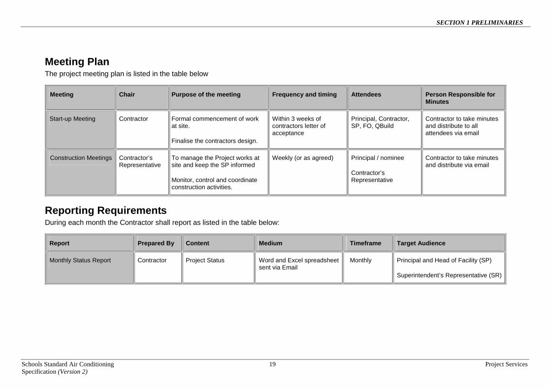
Meeting Plan The project meeting plan is listed in the table below
Meeting Chair Purpose of the meeting Frequency and timing Attendees Person Responsible for Minutes
Start-up Meeting Contractor Formal commencement of work at site.
Finalise the contractors design.
Within 3 weeks of contractors letter of acceptance
Principal, Contractor, SP, FO, QBuild
Contractor to take minutes and distribute to all attendees via email
Construction Meetings Contractor’s Representative
To manage the Project works at site and keep the SP informed
Monitor, control and coordinate construction activities.
Weekly (or as agreed) Principal / nominee
Contractor’s Representative
Contractor to take minutes and distribute via email
Reporting Requirements During each month the Contractor shall report as listed in the table below:
Report Prepared By Content Medium Timeframe Target Audience
Monthly Status Report Contractor Project Status Word and Excel spreadsheet sent via Email
Monthly Principal and Head of Facility (SP)
Superintendent’s Representative (SR)

SECTION 1 PRELIMINARIES
Schools Standard Air Conditioning 20 Project Services Specification (Version 2)
Site Meetings Hold and attend site meetings throughout the contract and ensure attendance of appropriate subcontractors, the Principal, and appropriate consultants.
- Frequency: Weekly meetings with Principal as per the above Meeting Plan.
Minutes: Keep minutes of site meetings. Within 3 working days after each meeting, submit to each party written copies of the minutes.
- Purpose of submission: Review.
Contacts: At the first site meeting, submit names and telephone numbers of responsible persons who may be contacted after hours during the course of the contract.

SECTION 2 SCOPE
Schools Standard Air Conditioning Project Services Specification (Version 2)
21
SECTION 2 SCOPE
1 GENERAL
1.1 SCOPE OF THIS SECTION This section outlines the minimum requirements for work associated with the provision of air conditioning systems and associated upgrade of the electrical reticulation system at the School. The work shall be carried out in accordance with all sections of this Specification and shall include, but not be limited to, the following:
• design, documentation and certification of all mechanical and electrical services by engineers who are certified Registered Professional Engineer of Queensland (RPEQ). Design, documentation and certification of all condensing units, evaporative cooling units, fan coil support frames and brackets by a structural engineer who is certified as a Registered Professional Engineer of Queensland (RPEQ);
• supply and installation of the split system air conditioning units, evaporative cooling units and mechanical ventilation as nominated in the briefing document.
• provision of outside air supply systems;
• provision of all associated ductwork, insulation, grilles, diffusers and filters;
• provision of all electrical subcircuit wiring and controls necessary for a fully operative installation;
• provision of all associated refrigeration, condensate drainage and water supply pipework;
• provision of make-up and relief air grilles as required for the operation of evaporative cooling and mechanical ventilation systems;
• all penetrations cutting and making good;
• electrical services upgrade as required to the site and individual buildings which have been nominated for air conditioning. Refer to Section 4 - Electrical Services IMPORTANT - Provide at tender time, details on the extent of electrical upgrading allowed for and also advise the amount allowed for that component of the work.
• all demolition and making good of all existing evaporative cooling and air conditioning works prior to
installation of new mechanical services;
• provision of pipework covers;
• provision of condensate lines from each air conditioning unit to a condensate drainage point;
• drainage lines from each evaporative cooling unit to a drainage point;
• provision of tundishes for the collection of air-conditioning condensate, evaporative cooling and mechanical ventilation fan drainage;
• provision of water supply with ball valve isolators to each evaporative cooling unit. All such water supplies shall be connected to the schools water supply mains;
• provision of concrete plinths for new air conditioning, evaporative cooling and mechanical ventilation units;
• provision of condensing unit enclosures;
• provision of lockable fenced enclosures for evaporative cooling units;
• provision of galvanised steel condensing unit and evaporative cooling support stands;

SECTION 2 SCOPE
Schools Standard Air Conditioning Project Services Specification (Version 2)
22
• provision of galvanised steel condensing unit wall mount brackets,
• provision of galvanised steel support brackets for the support of under ceiling fan coil units that may be required in addition to those supplied by the air conditioning unit supplier;
• provision of mechanical ventilation fan unit galvanized steel, wall or roof mount brackets;
• provision of weatherproof outside air intake louvres ducted for outside air systems;
• roof access ladders, walkways and platforms;
• rubble pits as required for the termination of air conditioning condensate, evaporative cooling and mechanical ventilation fan drain lines;
• cutting and/or removal of asbestos cement sheet;
• modifications to ‘T’ Bar ceiling support structures;
• provision of roof penetrations, roof upstands and flashing as required for the installation and support of air conditioning units, evaporative cooling units, fans and ductwork;
• removal of louvres or windows and fitment of fixed panels for the support of outside air fans and pipework penetrations;
• making good wall penetrations left after the removal of existing air conditioning and evaporative cooling units;
• removal, replacement and making good ceiling sheets as necessary to install mechanical services systems;
• relocation of existing services such as lights, fire detectors, security sensors and any other electrical fitting that clash with air conditioning unit locations or that hinders correct operation of the air conditioning or the existing services;
• provision of ceiling access panels necessary for maintenance of in-ceiling cassette type fan coil units; • provision of ceiling insulation for all areas exposed to a roof load that currently do not have roof or
ceiling insulation. This shall also include all areas that currently have roof and ceiling insulation that does not comply with the specified insulation requirements specified in the Section 3 - Mechanical Services design sections of this Specification. All such areas shall be provided with new or additional insulation as specified;
• where ceiling insulation is installed under this contract, relocate electrical cabling to an ‘enclosed in air’ - AS3000, AS 3008 zone prior to installation of roof insulation to avoid de-rating of existing and new electrical circuit cabling;
• testing and commissioning;
• operator training;
• service and maintenance of all equipment during the defects liability period
• provision of operation and maintenance manuals;
• all other works necessary for fully operative installations;
• Provision of ceiling fans (or wall fans if necessary) to areas being air-conditioned that do not currently have fans installed. In the teaching areas provide four fans. The location of ceiling fans is to be correctly coordinated with lighting and is to be approved by the Head of Facility. Refer to Section 4 - Electrical Services.
• isolation and removal of all electrical cabling and controls associated with any Evaporative Coolers which are to be removed.

SECTION 2 SCOPE
Schools Standard Air Conditioning Project Services Specification (Version 2)
23
• Removal of any existing bar heaters, in areas which are to be served by reverse cycle air conditioning systems, are to be removed along with all associated fixings, supports, electrical wiring and controls. The salvaged bar heaters shall be cleaned and handed over to the Head of Facility.
• Provision of RCD protection as specified, to all new circuits on existing switchboards, and all existing and new circuits required to be connected to any new or replacement switchboards.
2 DEMOLITION
2.1 General The removal of existing mechanical and electrical services shall be carried out in accordance with Section 5 – Demolition and all other sections of this Specification. The minimum requirements for this project include the following demolition works: • removal of all redundant evaporative and air conditioning systems;
• removal of all exposed redundant evaporative cooling systems ductwork and associated supports;
• removal and capping off of concealed ductwork grilles;
• removal of redundant concrete slabs, unit enclosures, support brackets and fixings;
• removal of redundant air relief grilles;
• removal of existing Mechanical Services Switchboards, wiring and controls where they are upgraded.
• removal and capping off of redundant hydraulic services;
• removal of existing Electrical Distribution Switchboards, and redundant cables where they are upgraded,
• removal of all redundant bar heaters, where reverse cycle air conditioning systems provide the heating capacity required,
• removal of all redundant electrical cabling, circuit breakers and isolation switches, and
• all works necessary to make good buildings and site following removal of the above items.
SECTION 2 SCOPE
Schools Standard Air Conditioning Project Services Specification (Version 2)
24
THIS PAGE INTENTIONALLY LEFT BLANK

SECTION 3 MECHANICAL SERVICES
Schools Standard Air Conditioning Project Services Specification (Version 2)
25
SECTION 3 MECHANICAL SERVICES
1 GENERAL
1.1 SCOPE OF THIS SECTION This section specifies the Principal’s minimum requirements for the design, installation and performance of air-conditioning, evaporative cooling and mechanical ventilation systems for this contract.
1.2 ACTS CODES AND STANDARDS
Mechanical Services shall be designed and installed in accordance with all Acts, Codes and Government Legislation relevant to this type of installation. The following as amended from time to time are noted for particular reference. • Building Code of Australia
• Workplace, Health and Safety Regulations
• AS/NZS 1668:1991, Part 2 Mechanical Ventilation in Buildings
• AS/NZS 1668:1998, Part 1 Smoke Control in Buildings
• AS/NZAS 3000:2007 Electrical Installations
• AS/NZS 3666 Air-handling and water systems of buildings
• AS 1939 Degrees of protection
• AS 1657 Fixed platforms, walkways, stairways and ladders and access ways
• AS/NZS 3500 Plumbing and drainage
• AS 1851 Maintenance of fire protection systems and equipment
• BS-848, ISO5801 or AS ISO 5801 Industrial fans - Performance testing
• AS 1345 Identification of contents of piping, conduits and ducts
• AS/NZS 61000 Electromagnetic compatibility (EMC)
• All other Legislation, Codes, Australian Standards and local Council Authority relevant to this type of installation or referred to elsewhere in this document
1.3 STATUTORY AUTHORITIES
Comply with the relevant requirements of the following authorities:
• Local Council
• Water supply and drainage authorities
• Electrical supply authority
• Fire service authority
• Workplace Health and Safety
1.4 INTERPRETATION
General Unless the context otherwise requires, the following definitions apply:
• Supply: ‘Supply’, ‘furnish’ and similar expressions mean ‘supply only’.
• Install: ‘Install’, ‘fix’ and similar expressions mean ‘supply, install, test and commission’.
• Provide: ‘Provide’ and similar expressions mean ‘supply, install, test and commission’.
• Proprietary: ‘Proprietary’ mean identifiable by naming manufacturer, supplier, installer, trade name, brand name, catalogue or reference number.

SECTION 3 MECHANICAL SERVICES
Schools Standard Air Conditioning Project Services Specification (Version 2)
26
• Samples: Includes samples, prototypes and sample panels.
Abbreviations • AS: Australian Standards.
• BCA: Building Code of Australia
• Natspec and QMech: Mechanical Services Reference Specifications
• DET Queensland Department of Education and Training
• DB Dry Bulb Temperature in °C
• WB Wet Bulb Temperature in °C
1.5 REFERENCE SPECIFICATIONS
Unless specified otherwise in this document, Mechanical Services shall comply with the requirements of the following Departmental NATSPEC and QMECH Reference Specifications: NATSPEC 0701 General Requirements (Mechanical) NATSPEC 0721 Packaged Air Conditioning NATSPEC 0722 Room Air Conditioners NATSPEC 0731 Fans NATSPEC 0732 Air Filters NATSPEC 0741 Ductwork NATSPEC 0744 Ductwork Insulation NATSPEC 0744 Attenuators and Acoustic Louvres NATSPEC 0746 Air Grilles NATSPEC 0781 Mechanical Electrical NATSPEC 0791 Mechanical Commissioning. NATSPEC 0792 Mechanical Maintenance QMECH 850-862 Evaporative Cooling The contractor is responsible for arranging their own copy of all NATSPEC & QMECH reference specifications. Other sections of this document may alter, override or exceed the requirements of the above and shall take precedence over the reference specifications listed. If ambiguities occur within this document the relevant NATSPEC or QMECH reference specification shall take precedence.
1.6 STANDARD DETAILS
The following standard details shall apply to this contract: WC-2009-M1 CONDENSING UNIT ENCLOSURE QN-881-02 CUSHION HEAD BOX DETAIL AND FLEXIBLE DUCT SCHEDULE
1.7 PERFORMANCE GUARANTEE
The Contractor shall guarantee that the air conditioning systems installed under this contract shall operate satisfactorily in automatic mode, maintaining the internal design conditions specified elsewhere in this document throughout all seasons of the year.
1.8 DESIGN CERTIFICATION
The contractor shall obtain, and provide to the Principal, certification for all mechanical services designs. A qualified mechanical services engineer who is a Registered Professional Engineer of Queensland (RPEQ) shall carry out the certification. The engineer shall certify that all design complies with the requirements of this specification and all other relevant codes and statutory requirements including those of the Building Code of Australia (BCA). The contractor should note that, in terms of ventilation for air conditioned areas, the mandatory requirement of the BCA is that all occupied spaces have either fixed openings or openable devices (such as windows and doors) that can make available openings into the space that are equal to at least 5% of the floor area.

SECTION 3 MECHANICAL SERVICES
Schools Standard Air Conditioning Project Services Specification (Version 2)
27
If the above requirement cannot be met, then compliance with the BCA is to be based on outside air being positively provided to the occupied space by way of mechanical ventilation systems. In that case, outside air shall be supplied to the occupied space in accordance with Australian Standard AS1668.2 (1991). This standard requires that outside air be supplied to classrooms at a rate of 12 litres/second/person.
1.9 DEFECTS LIABILITY PERIOD
For the mechanical services installations a 12 month defects liability shall apply from the date of Practical Completion. During that time the Contractor shall be responsible for maintaining and servicing all equipment and controls associated with the installation as necessary to maintain a fully operative installation.
1.10 CONTRACTOR SUPPLIED AIR CONDITIONING UNITS
Air Conditioning Equipment The air conditioners supplied for this contract shall be single phase power supply, reverse cycle, inverter technology, split systems and operate on 410A refrigerant. They shall utilize internal fan coil units of the wall mount, under-ceiling hung and in-ceiling cassette configuration as nominated and listed elsewhere in this document. The matching condensing units shall be external, horizontal blow configuration. For this contract the air conditioning fan coil unit configurations and nominal Total Cooling Capacities tabled below are to be utilized:
NOMINAL GTH (kW)
TYPE OF UNIT NATSPEC 0722 ROOM AIR CONDITIONERS
REFERENCE SPECIFICATION TYPE
2.5 Wall mounted SW
5 Wall mounted SW
8 Wall mounted SW
7 Under ceiling SC
10 Under ceiling SC
12.5 Under ceiling SC
14 Under ceiling SC
7 Ceiling Cassette SCR
10 Ceiling Cassette SCR
12.5 Ceiling Cassette SCR
14 Ceiling Cassette SCR
SW = Wall Mounted Fan Coil Unit SC = Under Ceiling Hung Fan Coil Unit SCR = Ceiling Cassette Fan Coil Unit Air Conditioning Equipment Manufacturers The air conditioning equipment used shall be from manufacturers having a well established brand name in Australia and have been supplying equipment into Australia for a minimum of 10 years. The equipment manufacturer shall have a well established service and spare parts support network within Queensland. Some brands that have previously been used for school air conditioning projects and that would be acceptable for this contract are; Mitsubishi Heavy Industries, Daikin and Mitsubishi Electric.

SECTION 3 MECHANICAL SERVICES
Schools Standard Air Conditioning Project Services Specification (Version 2)
28
A maximum of two brands of air conditioning equipment may be used for any given school site. For air conditioned areas served by two or more air conditioning units, or multiple air conditioners controlled by one central control panel, those units shall be the same brand of air conditioner. All equipment shall comply with all current Legislation, Codes and Australian Standards covering that type of equipment. For all air conditioning equipment supplied, the installing mechanical sub-contractor shall be a manufacturer’s registered service, warranty support and spare parts supply agent for that equipment.
Air Conditioning Equipment Warranty All air conditioners installed shall be supplied with a five year manufacturer’s warranty. This warranty shall include the following: • A five year warranty on all parts and labour. Units determined as faulty by the Principal are to be repaired
or replaced; • Faulty units are to be replaced or repaired and fully commissioned within a ten (10) working day period
from the time of notification. All costs including CPI and inflation or foreign exchange currency shall be borne by the supplier/s of the equipment.
• The five years warranty shall take effect on the date of Practical Completion of the air conditioning installation. The Contractor shall forward a copy of the Certificate of Practical Completion to the equipment supplier.
It is the installing contractor’s responsibility to maintain the equipment for the first twelve months of the five year warranty period as necessary to maintain the warranty in accordance with the equipment manufacturer’s requirements. The provision of such warranty support may necessitate the need for the mechanical sub-contractor to engage a local contractor within the school region. The warranty must be on the basis that, following the twelve months defects liability period, the school will use their own nominated service agents to maintain the systems. This may not necessarily be the equipment supplier or manufacturer’s service agents. Air Conditioning Unit Controls The under ceiling hung (SC) and ceiling cassette (SCR) split system air conditioning units supplied for this contract shall have on-board controls that can accept inputs from custom built occupant control panels specified elsewhere in this document. For the wall mount (SW) type fan coil units, such an input may not be available as part of the fan coil unit’s on-board controls. In those cases, supply and install ancillary controls to achieve the input required. All ancillary controls for the control of the air conditioning units shall be proprietary items sourced from the air conditioner supplier and installed in strict accordance with the manufacturer’s recommendations so as to maintain the manufacturer’s full warranty. Ceiling Cassette Unit Condensate Pump All Ceiling Cassette fan coil units shall be supplied with a factory fitted, proprietary condensate pump. The air conditioning unit shall have factory supplied, on-board controls to ensure the following condensate pump operation: • Pump to operate whenever the air conditioning unit is operating. • In the case of a pump failure, air conditioning unit to cease operation.
Air Conditioning Equipment Operational Parameters All air conditioning equipment shall be capable of continuous operation within the parameters listed in the following table.

SECTION 3 MECHANICAL SERVICES
Schools Standard Air Conditioning Project Services Specification (Version 2)
29
Air Conditioning Equipment Operational Parameters Extreme ambient conditions within which plant shall be required to operate:
Summer: 45oC DB and full solar load
Outside ambient conditions in which air conditioning plant shall be required to continuously achieve the design capacity:
Summer: 40oC DB, 23.5o WB and full solar load. The contractor shall confirm these conditions by reference to CAMEL design software design conditions. If CAMEL conditions are not available refer to Bureau of Meteorology
Internal conditions in which air conditioning plant shall be required to continuously achieve the required design capacity:
Summer: 26oC±1K DB; 55% RH (not controlled) Winter: 21oC±1K DB; 55% RH (not controlled)
Electricity supply: Nominal 415 V, 50 Hz, balanced three phase, earthed neutral; otherwise in accordance with AS 2926, Standard voltages, at the consumer’s terminals
Air Conditioning Equipment Sensible to Total Cooling Capacity Ratios Within the limits of the split system technology cooling coil sensible to latent capacity ratios, the equipment supplied shall be selected to meet the calculated air conditioning sensible and latent capacity requirements. It is acknowledged that, for some calculated capacities, a matching equipment selection will not be achievable. Within such constraints, the equipment Sensible Cooling Capacity shall at least match the calculated required Sensible Cooling Capacity when operating within the design ambient and specified internal room conditions. So as to achieve an acceptable Sensible Cooling Capacity to Total Cooling Capacity ratio, the range of equipment to be used for this contract shall have the ratios as tabled below:
NOMINAL GTH (kW)
TYPE OF UNIT NATSPEC 722 REFERENCE
SPECIFICATION TYPE
MAXIMUM SENSIBLE COOLING CAPACITY TO
TOTAL COOLING CAPACITY RATIO
2.5 Wall mounted SW 0.9
5 Wall mounted SW 0.78
8 Wall mounted SW 0.76
7 Under ceiling SC 0.75
10 Under ceiling SC 0.75
12.5 Under ceiling SC 0.75
14 Under ceiling SC 0.75
7 Ceiling Cassette SCR 0.79
10 Ceiling Cassette SCR 0.75
12.5 Ceiling Cassette SCR 0.75
14 Ceiling Cassette SCR 0.75
Note: The Sensible ratios listed above are based on a coil air-on condition of 260C DB / 19 0C WB and an
external ambient air temperature of 400C DB.
SECTION 3 MECHANICAL SERVICES
Schools Standard Air Conditioning Project Services Specification (Version 2)
30
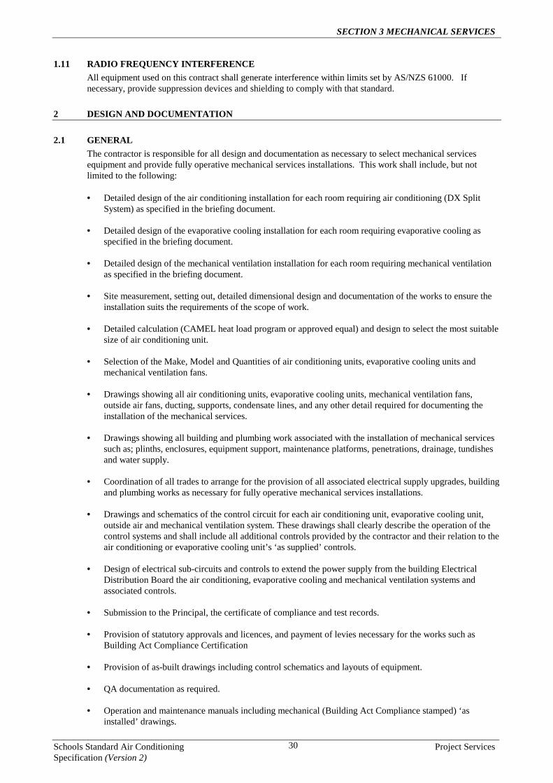
1.11 RADIO FREQUENCY INTERFERENCE
All equipment used on this contract shall generate interference within limits set by AS/NZS 61000. If necessary, provide suppression devices and shielding to comply with that standard.
2 DESIGN AND DOCUMENTATION
2.1 GENERAL
The contractor is responsible for all design and documentation as necessary to select mechanical services equipment and provide fully operative mechanical services installations. This work shall include, but not limited to the following: • Detailed design of the air conditioning installation for each room requiring air conditioning (DX Split
System) as specified in the briefing document.
• Detailed design of the evaporative cooling installation for each room requiring evaporative cooling as specified in the briefing document.
• Detailed design of the mechanical ventilation installation for each room requiring mechanical ventilation as specified in the briefing document.
• Site measurement, setting out, detailed dimensional design and documentation of the works to ensure the installation suits the requirements of the scope of work.
• Detailed calculation (CAMEL heat load program or approved equal) and design to select the most suitable size of air conditioning unit.
• Selection of the Make, Model and Quantities of air conditioning units, evaporative cooling units and mechanical ventilation fans.
• Drawings showing all air conditioning units, evaporative cooling units, mechanical ventilation fans, outside air fans, ducting, supports, condensate lines, and any other detail required for documenting the installation of the mechanical services.
• Drawings showing all building and plumbing work associated with the installation of mechanical services such as; plinths, enclosures, equipment support, maintenance platforms, penetrations, drainage, tundishes and water supply.
• Coordination of all trades to arrange for the provision of all associated electrical supply upgrades, building and plumbing works as necessary for fully operative mechanical services installations.
• Drawings and schematics of the control circuit for each air conditioning unit, evaporative cooling unit, outside air and mechanical ventilation system. These drawings shall clearly describe the operation of the control systems and shall include all additional controls provided by the contractor and their relation to the air conditioning or evaporative cooling unit’s ‘as supplied’ controls.
• Design of electrical sub-circuits and controls to extend the power supply from the building Electrical Distribution Board the air conditioning, evaporative cooling and mechanical ventilation systems and associated controls.
• Submission to the Principal, the certificate of compliance and test records.
• Provision of statutory approvals and licences, and payment of levies necessary for the works such as Building Act Compliance Certification
• Provision of as-built drawings including control schematics and layouts of equipment.
• QA documentation as required.
• Operation and maintenance manuals including mechanical (Building Act Compliance stamped) ‘as installed’ drawings.

SECTION 3 MECHANICAL SERVICES
Schools Standard Air Conditioning Project Services Specification (Version 2)
31
• Operator Training
2.2 DESIGN REVIEW
The Principal reserves the right to review and approve all designs, CAMEL heat loads, calculations and equipment selections used to achieve the design and performance parameters specified in this section. All such design data shall be provided to the Principal on request.
2.3 AIR CONDITIONING SYSTEMS DESIGN
2.3.1 Design Parameters and Performance Guarantee The Contractor shall guarantee that the entire system and each of its components will start up, shut down and operate stably, safely and reliably within the design parameters as shown in the following table:
Air Conditioning Design and Performance Parameters
Extreme ambient conditions within which plant shall be required to operate:
Summer: 45oC DB and full solar load
Outside ambient conditions in which air conditioning plant shall be required to continuously achieve the design capacity:
Summer: 39.9oC DB, 23.2o WB and full solar load. The contractor shall confirm these conditions by reference to CAMEL design software design conditions. If CAMEL conditions are not available refer to Bureau of Meteorology
Internal conditions in which air conditioning plant shall be required to continuously achieve the required design capacity:
Summer: 26oC±1K DB; 55% RH (not controlled) Winter: 21oC±1K DB; 55% RH (not controlled)
Ventilation If the air conditioned space is assessed to comply with the natural ventilation requirements of the Building Code of Australia, an outside air rate of 5l/s per person may be used on the condition that the outside air is supplied by the methods specified under Clause 2.3.4 Outside Air Supply.
If the room does not comply with the natural ventilation of the Building Code of Australia, then outside air shall be supplied to each room in accordance with AS1668-2 (1991).
The contractor shall ensure that the system is able to efficiently provide not less than the specified performance at full load and at partial loads as required by the design parameters and that the required ratings are maintained during the defects liability period. Automatic controls, motors and switchgear and every other component of the entire system must be selected, installed and adjusted for continuous, safe, unattended operation at the specified limiting conditions and be adjusted to comply with this requirement at the time of commissioning. The installation shall be guaranteed to continuously maintain the required design capacity under the specified ambient conditions and to continue to operate without damage under the extreme operating conditions specified in the above table.
Design Safety Factors Over sizing of equipment can cause a high rate of on/off compressor cycling. This can result in high electrical consumption and poor relative humidity control. In light of these issues, it is recommended a safety factor be used only where the building is sufficiently complex as to make it difficult to model with the software being used for the heat load calculations. If it considered that a safety factor is required, then a total safety factor of 5% is considered appropriate.

SECTION 3 MECHANICAL SERVICES
Schools Standard Air Conditioning Project Services Specification (Version 2)
32
Design Occupancy Levels When calculating the required air conditioning capacities for classroom spaces, the contractor shall allow a maximum of one person per 2m2 of floor area up to a maximum of 29 persons in any space. For spaces identified as multiple teaching areas, each separable portion shall be treated as a completely separate classroom with 29 persons applied to each area. In addition, the determination of floor area for occupancy rates shall be based on that space specifically set aside for classroom activities. Modifications that have been made to buildings to increase classroom floor areas (such as closed in verandah areas), that are not used as the primary classroom space shall be excluded when calculating floor areas for determining occupancy rates. For main spaces of Resource Blocks occupancy rates shall be based on one person per 3m2 of floor area of floor areas less than 200 m2 and one person per 4m2 of floor area for areas above 200m2.
For all other areas, the contractor shall liaise with the Head of Facility to determine occupancy levels in terms school usage.
Multiple Teaching Areas All spaces identified by the Head of Facility as Multiple Teaching Areas shall, for the purposes of selecting and installation of air conditioning units, be considered as individual classroom spaces. This shall apply whether or not the area is currently fitted with separating concertina doors. In the determination of required capacities and equipment selections, the contractor shall allow for future modifications where the multiple teaching space will be divided by concertina doors or fixed partitions into individual classrooms. Ceiling Insulation Designs to determine air conditioning capacities for all areas adjacent to the roof level of buildings shall include an allowance for ceiling or roof insulation. Where no roof or ceiling insulation exists above areas where new air conditioning is to be installed, then new ceiling insulation shall be installed to all such areas. All new insulation shall be Bradford R3.0 Polyester or approved equal For air conditioned areas where roof or ceiling insulation already exists, the contractor shall determine the thermal properties of that existing insulation and apply this rating in design calculations. Existing roof and ceiling insulation shall only be considered for continued use if the thermal properties are determined to be at least R3.0. For insulation that does not meet this criterion then new or additional insulation shall be installed to meet the rating for new insulation as specified above.
2.3.2 Noise Levels Internal Noise Levels Noise levels in air conditioned spaces shall not exceed NR40.
Noise level measurements within the air conditioned spaces shall be taken at 1500mm above the floor level at
all areas within the space. Noise levels shall not be measured closer than 1m from any flat surface such walls and ceilings.
Internal noise levels in areas adjacent to operating equipment associated with the air conditioning installations
shall not have noise impingements of levels higher than those listed above for air conditioned spaces. Outside Air Supply Systems Outside air fans and systems shall not produce a noticeable increase in the overall internal noise level that is above that of ‘air conditioning units only’ operation (i.e. the noise levels with ‘air conditioners only’ operating, should not be noticeably higher when air conditioners and outside air fans are operating together.) The determination of ‘noticeable’ shall be at the discretion of the Principal The Contractor shall, if requested by the Principal, provide sound measuring instruments to assess the actual resultant noise levels produced by the installed system or individual components of that system.”
External Noise Levels • Noise levels at site boundaries shall meet all local Government requirements for the area and the Division
of Noise Abatement and Air Pollution Control.

SECTION 3 MECHANICAL SERVICES
Schools Standard Air Conditioning Project Services Specification (Version 2)
33
• Noise levels shall not exceed 40 dBA at site boundaries or within 3 metres of noise sensitive areas of the
school site.
2.3.3 Air Conditioning Unit Selection and Positioning The contractor shall select air conditioning units that, in addition to achieving the required cooling load capacity, can be located to achieve even supply air distribution and efficient cooling of all areas within the air conditioned space.
2.3.4 Outside Air Supply Outside air shall be mechanically supplied to all classroom spaces which are to be air conditioned under this contract. The outside air rate shall comply with the performance requirement as specified under Clause 2.3.1. or as necessary to meet the requirements of the Building Code of Australia(BCA). As previously noted, the contractor should note that; in terms of ventilation, the mandatory requirement of the BCA is that all occupied spaces have either fixed openings or openable devices (such as windows and doors) that can make available openings into the space that are equal to at least 5% of the floor area. If the above requirement cannot be met, then compliance with the BCA is to be based on outside air being positively provided to the occupied space by way of mechanical ventilation systems. In that case, outside air shall be supplied to the occupied space in accordance with Australian Standard AS1668.2 (1991). This standard requires that outside air be supplied to classrooms at a rate of 12l/s per person. For areas to be ventilated in accordance with AS1668.2, the contractor shall confirm with the Principal the actual number of occupants in the space to determine the required outside air quantities. Notwithstanding this requirement for the determination of outside air quantities as mentioned above, the contractor shall, in calculating the outside air quantities for classroom spaces, limit the outside air based on a maximum of one person per 2m2 of floor space and up to a maximum of 29 persons in any classroom space. In general, classroom spaces are to accommodate 28 students and one staff member. Outside air may be introduced into the air conditioned spaces by the following methods: • Proprietary wall or window mounted fan units consisting of a weatherproof intake louvre, centrifugal fan,
filter and room outlet.
• A soffit or roof gable mounted intake grille through a ducted system including a filter, fan and ceiling mounted supply air outlets.
For small areas such as staff offices, outside air may be introduced via a small proprietary wall or window mounted axial fan unit consisting of a weatherproof intake, axial fan and room outlet. Provide electrical interlocks between air conditioning units and the outside air fans as specified elsewhere in this document. Wall Mounted Outside Air Fan Units The contractor shall provide proprietary wall mounted fan units. Axial Fans Where a wall mounted axial fan is used, the contractor shall provide a single-phase fan unit that has a weatherproof intake grille, an axial fan and inlet grille. No filter is required in this case. The fan speed shall be adjustable to meet the air quantity required. Centrifugal Fans Where a wall mounted centrifugal fan is required the contractor shall supply and install a proprietary filtered supply air unit.

SECTION 3 MECHANICAL SERVICES
Schools Standard Air Conditioning Project Services Specification (Version 2)
34
The wall mounted centrifugal fan shall be a single-phase, multiple speed, fan unit that has a vermin and weather proof intake, a galvanised steel or polypropylene centrifugal fan, a minimum 345x345 face dimension ‘V’ form 100 deep filter and an outlet to discharge air into the air conditioned space. The filter shall consist of an aluminium frame that is fixed in place with over-centre or quarter turn catches. The filter must be positively sealed by way of a closed cell or neoprene seal to minimise air bypass around the filter. To allow easy and regular servicing of the filter, the fan unit box design shall be such that the filter is easily accessible from inside the air conditioned space. The filter media is to be a minimum G4 washable or disposable F5 in accordance Table 2.1 of Australian Standard 1324.1. If an F5 disposable filter is used it shall be a synthetic material able to be washed on a regular basis without significant degradation of performance. The media shall be supported by a wire mesh grid bonded to both faces of the media and formed into a ‘V’ configuration to achieve maximum surface area within the specified filter face area. The fan speed shall be adjustable in set increments such as via an auto-transformer or multi-speed motor. An infinitely variable speed controller is not acceptable and fans utilising such a controller will be rejected. In order to minimise occupants of the room experiencing ‘hot spots’, the fan outlet shall consist of a flat plate in front of the fan discharge to deflect the air parallel to wall or window opening in which the fan is mounted. The fan discharge shall not take the form of an eggcrate grille, louvre, double or single deflection register that discharges air away from the wall’s surface. The fan discharge panel shall be fixed in place with dome nuts. The unit case, weatherproof intake and air outlet shall be constructed from powder coated, 1.2mm minimum thickness, zinc coated sheet steel. The flat plate discharge panel shall be formed to include a safe edge return to provide strength to the panel and avoid any possibility of harm to persons that come in contact with the fan. The fan speed shall be adjustable in set increments as previously noted. The speed increments shall be capable of meeting the air quantity specified. The contractor shall provide proof of fan performance in the form of a test certificate for the actual installed fan design being tested on a test rig that meets the latest version of test standard BS848 Part 1 and incorporated in ISO5801. The certificate shall show the airflows produced at each of the fan unit’s set speed increments. The fan testing shall be by a recognized authority certified to carry out such tests. Failure to produce such a test certificate will result in immediate rejection of the outside air fans. It should also be noted that rejection of the fans shall apply to any fans that vary in any way from that fan design covered by the certification. Any modifications, such as those required to meet the noise level requirements of this specification, that are carried out after fan certification, are to be retested and a new certificate issued before such a fan will be accepted.
A maximum variance of -10% is allowable on the outside air quantities. Ducted Outside Air Systems Air distribution from ducted outside air supply grilles shall provide even, draught free air movement and be readily amenable to modifications to suit partitioning modifications. Air movement to be between 0.10 m/s and 0.25 m/s in occupied spaces measured 1.0 m to 1.5 m above floor level. When a ducted system is used a maximum of 130 l/s per outlet shall be provided. Ductwork shall be concealed within the building fabric wherever possible, eg. ceiling/roof voids. Where ductwork cannot be concealed, design and install a surface mounted ductwork installation to the Principal’s approval. Ducted outside air systems shall generally consist of a soffit mounted eggcrate grille or roof gable mounted weatherproof louvre intake, a ‘V’ form filter, centrifugal fan, flexible ductwork and a ceiling mounted diffuser outlet. The ceiling diffuser shall be an air conditioning type ceiling diffuser to achieve a coanda discharge effect such that the air is deflected parallel to the ceiling. Eggcrate or double deflection registers are not acceptable and shall not be used for the introduction of outside air. The ceiling outlet shall be mounted in a cushion head box. Outside air shall not be directly connected to air conditioning units. Intake to the ductwork shall be fitted with galvanised steel vermin mesh. The filter media is to be a disposable Grade F5 in accordance with Table 2.1 of Australian Standard 1324.1. The fans shall be axial for quantities up to 100 l/s and centrifugal for quantities 100 l/s above. Fans may be single or three phase electrical supply. Provide internal ductwork insulation only as required to meet the noise criteria specified.

SECTION 3 MECHANICAL SERVICES
Schools Standard Air Conditioning Project Services Specification (Version 2)
35
Outside air distribution shall be arranged to provide discharge into the room such that good mixing of room and outside air is achieved before air is returned to the air conditioning unit. Outside air outlets can be located adjacent to air conditioning return air grille only if a stable and reliable return air temperature can be sensed. In addition to the criteria above, outside air should be introduced into spaces in such a way as to avoid occupants experiencing any ‘hot spots'. Outside air volumes shall be balanced proportionally between each air conditioning unit serving the space.
2.3.5 Ductwork
Supply air ductwork: Element Criteria Main supply air or ventilation duct, Velocity in duct to be 6.0 m/s maximum and have a maximum 0.8 Pa/m static resistance Supply, return or ventilation ductwork Velocity in duct to be 4.5 m/s maximum
adjacent to supply or return air grilles. Neck velocity for supply air outlet 2.5 m/s maximum Pressure drop is not to exceed 80 Pa between first and last outlets. Flexible ducts Final connection to supply air grilles and flexible duct sizes are to be in accordance with those shown Standard Drawing QN-881-02 bound into this document.
2.3.6 Miscellaneous Plant Element Criteria Air Filters In accordance with the filter supplier’s recommendations but
not exceeding 2.5 m/s maximum face velocity Door & Transfer Grilles 2.5 m/s through free area Outside Air Louvres & Grilles. At a velocity such that there is no water ingress with a
maximum face velocity of 2.5m/s.
2.3.7 Control Systems General Provide a complete and fully automatic electronic control system which allows year round operation of the plant to meet the specified conditions without manual adjustment and which shall include all safety devices to provide complete protection of the plant. All control components shall be proprietary manufacture and proven design from a recognized supplier with comprehensive stock backup, held in Australia. Control components shall be of the same manufacture, however, where this is not possible, proposed controls not of the same manufacture as the majority of controls, shall be submitted for approval. Provide current generation systems of robust, tamper-proof fully compatible controls, from the current range of recognized control manufacturers, for which stocks of replacement parts, spares and service facilities are readily available in Queensland. Qualified service and maintenance personnel fully familiar with the equipment shall be available twenty-four hours per day with spare parts availability on twenty-four hours notice. After acceptance of tender, wiring schematics showing each component shall be submitted for perusal before preparation of wiring diagrams.

SECTION 3 MECHANICAL SERVICES
Schools Standard Air Conditioning Project Services Specification (Version 2)
36
The calibration, function and sequence of operation shall be checked and adjusted, if required, by a competent controls technician at six monthly intervals (to coincide with the Level 2 service visits) during the Defects Liability Period. Include the outcome of each visit in the service report. Each item of control equipment shall be clearly marked by an engraved traffolyte label or other approved means to indicate the function it performs. Provide necessary auxiliary field devices such as room temperature sensors, local control panels, time switches, etc. and external control cabling as required to interface with the integral equipment controls and to provide a fully automatic control system. Controls for can be either 24 or 240 volt. Commission and test all systems and calibrate all temperature sensors. Air Conditioner and Outside Air Fan Controls Control of air conditioning is to be achieved by the three methods listed below. The required control method to be used for each area is to be confirmed with the Principal. • Proprietary
This method is the typical method of control for staff only related areas. This method shall utilise the air conditioning supplier’s standard controller. Operation of outside air fans shall be via an ON/OFF toggle switch located on the wall adjacent to the air conditioner controller.
• Timer control This method is to be used for all student-related spaces. This method shall utilise a control panel that incorporates the following functions. - An ‘ON’ press button. Pressing this button shall, via a 0-8 hour adjustable timer, initiate the
operation the air conditioning unit/s and, after a time delay of 10 minutes, the outside-air fan/s. - An ‘OFF’ press button that will override the ‘ON’ and shut off the air conditioning unit/s and outside
air fan/s. - A green ‘RUN’ light to indicate air conditioning system operation.
• Timer control with purge This method is to be used for student-related spaces where there is a build-up of obnoxious fumes such as in art and science classrooms. This type of control is identical to the Timer control method specified above except a purge cycle timeclock is to be introduced to purge the rooms of any build-up of fumes prior to use by staff and students. This method shall utilise a control panel that incorporates the following functions. - An ‘ON’ press button. Pressing this button shall, via a 0-8 hour adjustable timer, initiate the
operation the air conditioning unit/s and, after a time delay of 10 minutes, the outside-air fan/s. - An ‘OFF’ press button that will override the ‘ON’ and shut off the air conditioning unit/s and outside
air fan/s. - A green ‘RUN’ light to indicate air conditioning system operation. - A 7-day, purge cycle timeclock that automatically operates the outside fan/s for a period of 30
minutes (adjustable up to 1 hour) between 6:30am and 7:00am Monday to Friday. - A Yellow ‘PURGE’ light to indicate when the outside air fan/s are operating in purge mode. - An air conditioning Enable/Disable switch to allow the school to disable operation of the purge cycle
during school holidays.
Note: With the switch in the ‘Disable’ mode, the air conditioning system controls shall be arranged such that the air conditioning cannot be operated via the ‘ON’ button as specified for normal operation. This is to ensure the automatic purge function will occur at all times of the year the air conditioning is required.
With the purge switch in the Enable mode, pressing the ‘ON’ button to operate the air conditioning system shall override the purge mode to allow normal operation of the air conditioning system.

SECTION 3 MECHANICAL SERVICES
Schools Standard Air Conditioning Project Services Specification (Version 2)
37
The timeclock and associated controls used to operate the purge cycle shall be sourced from the same manufacturer as supplies the timer controls for the normal ON/OFF operation of the air conditioning unit/s and outside air fan/s. However, the purge cycle controls must not be an integral part of the air conditioning system operation controls but must be supplied and fitted as a distinct optional extra to the controls.
The timer controlling operation of the air conditioning units shall initially be set to run for 2 hours unless otherwise specified by the Principal. The run hours are to be confirmed with the Principal.
The ON/OFF controls for the air conditioning and outside air fan/s shall be designed to allow the system to be turned off at any time within the run time cycle. Pressing the ‘OFF’ button shall immediately stop the air conditioning run cycle and return the system to its original state prior to the ‘ON’ button being pressed. This includes the first 10 minutes of operation when only the air conditioning units are operating. Furthermore, at the end of the 2 or 8 hour run time, the controls shall also allow for the immediate reactivation (without delay) of the air conditioning system cycle. In other words, Pressing the ‘ON’ at the end of a 2 or 8 hour run cycle must immediately allow the air conditioning units to automatically operate under their own controls.
All timers are to be inaccessible to the building occupants and as such shall be located in a controls enclosure as specified elsewhere in this section of the document. Multiple air conditioning units and outside air fans that are serving the one space shall be operated via a single controller and shall run together as a single operating system. Double Teaching Areas Any space identified by the Head of Facility as a Double Teaching Area, but does not have a separating concertina partition shall, for the purposes of air conditioning controls, be considered as one individual classroom space. Any space identified by the Head of Facility or in this document as Double Teaching Areas but does have a separating concertina partition shall, for the purposes of air conditioning controls, be considered as two individual classroom spaces. The exception to this shall be Double Teaching spaces in modular buildings. In this case, unless specifically requested by the Head of Facility, the contractor shall install a control panel for each half of that Double Teaching area.
2.3.8 Control Panels Control panels incorporating the control functions listed above shall be positioned at 1500mm above the floor and adjacent to light switches in the air-conditioned space. Where possible, the control panels shall match adjacent light switches. Only those controls associated with user operation shall be housed in this panel and shall be 24 volt maximum. The panels shall be clearly labelled ‘AIR CONDITIONING’. In addition, each function on the panel shall be labelled to indicate operation ie ‘AIR CONDITIONING ON’, ‘AIR CONDITIONING OFF’, PURGE CYCLE OPERATING, PURGE CYCLE ENABLE/DISABLE SWITCH. Control panels for the ‘proprietary’ installations shall have unit manufacturer’s controller positioned on the wall at 1500mm above the floor and adjacent to light switches in the air-conditioned space. The outside air fan controller shall be a flush mount panel to match adjacent light switches and be located adjacent to, and at the same height as, the air conditioning unit controller. Provide clear labelling above each item to indicate operation ie. ‘AIR CONDITIONING CONTROL’ and ‘FRESH AIR FAN SWITCH’. Also provide under the ‘FRESH AIR FAN SWITCH’ a label with the wording ‘ FAN MUST BE ON WHEN AIR CONDITIONER IS OPERATED’. A single control panel shall control, and simultaneously operate, all air conditioning units serving one area. It shall also simultaneously initiate the 10-minute delay operation of all outside air fan units associated with those air-conditioning units. Following a call to operate from the control panel, sequenced start-up of each individual air-conditioning unit shall be achieved by the unit’s internal controls. A call to stop, from either the manual stop button or via the timer, shall stop operation of all equipment serving the space.

SECTION 3 MECHANICAL SERVICES
Schools Standard Air Conditioning Project Services Specification (Version 2)
38
2.3.9 Fresh Air Label Fix to wall above each air conditioning control panel, an engraved traffolyte label as follows:
FRESH AIR PROVISION
When the air conditioning system is operating, outside air is mechanically supplied to the classroom. However, if stuffiness occurs, some windows should be opened to provide additional fresh air.
The title for the label ‘FRESH AIR PROVISION’ shall be 20mm high lettering. All other lettering on the label shall be 10mm high. All lettering shall be black engraved into a white background.
2.3.10 Controls Enclosures All controls shall be located in a tamper proof metal or PVC enclosure. This enclosure shall house such items as timers, equipment supplier’s controllers and thermostats. In general, enclosures shall be located at high level on the wall of the air-conditioned space. Enclosures serving rooms that are fitted with T-Bar ceilings are to be mounted above the ceiling in a location that is easily accessible for service or adjustment by service personnel. In such cases, the Contractor shall provide an engraved traffolyte label on the T-Bar under the enclosure indicating the location of that enclosure above the ceiling. Summer/Winter Changeover For all reverse cycle air conditioners in student related areas which are timer controlled, the air conditioning unit proprietary hard wired controller shall be housed in a separate lockable, hinged door enclosure. The purpose of this enclosure is to allow adjustment of summer and winter temperature settings for authorised staff such as the School Janitor. The hinged door of the enclosure shall operable via a quarter turn keyed latch to suit State Government switchboard key No. 92268. Provide two keys for each enclosure. The enclosure shall be located above or beside the occupant air conditioning control room. Fix to the front of the enclosure a traffoltye label clearly engraved with the following wording:
AIR CONDITIONING
SUMMER / WINTER TEMPERATURE ADJUSTMENT For Summer set to 26 0C For Winter set to 210C
2.3.11 Air Conditioning Units Control
To achieve the control functions specified above, the contractor shall provide all modifications and additional control items as necessary to the air conditioning units. The level of modification required will be dependent on brand of air conditioning unit supplied. The contractor shall liaise with the respective equipment manufacturer to determine the full extent of works necessary to provide a fully operative installation. The contractor shall seek written approval from the equipment manufacturer that any modifications and additional controls provided under this contract do not void the equipment warranty. All additional control items are to be approved and installed in accordance with the manufacturer’s recommendations.
2.3.12 Power Failure In the event of a power failure, all equipment shall, after reinstatement of power, automatically return to its operational state prior to the failure. The exclusion to this shall be single-phase units serving staff only areas. In this case it is acceptable for the occupants of the space to reset the temperature using the infra-red remote controller.
2.3.13 Control System Isolator The position of the Control Circuit Isolator, as required by clause 1.7.13 and 2.8.3 of AS / NZ 3000-2000, shall be clearly visible to Service Personnel. If remote, the isolator position shall be nominated by an engraved

SECTION 3 MECHANICAL SERVICES
Schools Standard Air Conditioning Project Services Specification (Version 2)
39
sign on the front of the Controls Enclosure in each room.
2.3.14 Equipment Power Isolators Locate adjacent to each air conditioning condensing unit and ducted outside air fan a lockable isolation switch. In general, electrical isolation switches shall not be used for the connection of power supply to wall mounted outside air fans. The power supply for outside air fans shall be via a direct connection to the switchboard from which the power source for the fan is derived. In these cases, an engraved label shall be fixed to the front of the fans advising the point of power isolation. The only exception to the above power connection requirement is where an on-wall fan switch is to be provided for staff-only related areas.
2.4 EVAPORATIVE COOLING SYSTEMS DESIGN 2.4.1 General
Where evaporative cooling is listed in the briefing document, design evaporative cooling systems to meet the minimum supply air and air change rates as scheduled in that section. All evaporative cooling units installed shall be new, commercially available in quantity production, and well proven in field operation within Queensland. Tenders shall allow for installation of the preferred system as scheduled in the briefing document. The tender shall allow for all ductwork, grilles and controls necessary for a complete and operative installation. If during the design stage, contractors see it necessary to vary the preferred type of systems from that specified in the briefing document, they shall seek the approval of the Principal prior to construction.
2.4.2 Evaporative Cooling Unit Selection Selection evaporative cooling units shall be in accordance with QMech Reference Specification 850-862. Where there is any reference in this Reference Specification to ‘QMECH PROJECT SCHEDULE’ cross reference the relevant sections to the following: Manufacture Supply: The units shall utilise cooling only, with top, side or bottom ducted discharge as necessary to
introduce and provide even distribution of air in the conditioned space.
The minimum evaporative efficiency to be achieved shall be 80%. Ambient Design Conditions: Summer design ambient conditions in the location of the building as found
in CAMEL design software design conditions. If CAMEL conditions are not available refer to Bureau of Meteorology
Performance: The system shall be designed to provide sufficient cooling to the spaces it conditions with
the design restrains of 55 to 80 Air Changes per Hour. Construction: All units supplied shall be constructed from high strength Structural Polymer as specified in
QMech 850- 862 Section 3.4. This shall include the evaporative pad support louvres and fan housing.
Fan wheels for all units shall be forward curved one-piece moulded polypropylene statically and dynamically balanced.
Fan drive shafts shall be stainless steel. Evaporative pads shall be Aspen Wood Supply air fans shall be single or three phase, belt drive, forward curved centrifugal.
Unit Control: Each evaporative cooling unit shall be installed with the unit manufacturer’s proprietary
control panel. The panel shall incorporate the minimum functions as specified in Qmech Reference Specification 850-862. The control panel shall be positioned at 1500mm maximum above the floor and adjacent to light switches in the conditioned space. Provide

SECTION 3 MECHANICAL SERVICES
Schools Standard Air Conditioning Project Services Specification (Version 2)
40
labelling to identify the control panel use and functions.
Each evaporative cooler shall be fitted with a dump valve as specified for school buildings. Plinth: Provide concrete plinths wherever evaporative cooling units are to be ground mounted. Run-on timer Each evaporative cooling unit shall also be fitted a timer to provide fan run-on after the water pump is stopped. The purpose of this run-on is to dry out the duct system after use. The timer shall be a 0-30 minutes adjustable. The timer shall initially be set to provide fan run-on of 10 minutes.
Pre-wetting of Evaporative Pads Evaporative cooling unit controls shall include a time delayed start of the fan motor to allow the water circulation pump to start first and pre-wet the evaporative cooling pads. The delay timer used shall be adjustable from 0 to 15 minutes. Initial setting of the timer shall be 5 minutes or longer as may be necessary to completely wet the pads prior to fan operation. Off Season Covers Each evaporative cooling unit shall be supplied with a polyweave draft-proof cover or similar, with securing lugs.
2.4.3 Ceiling Insulation Where no roof or ceiling insulation exists above areas where new evaporative cooling is to be installed, then new ceiling insulation shall be installed to all such areas. All new insulation shall be Bradford R3.0 Polyester or approved equal For evaporative cooled areas where roof or ceiling insulation already exists, the contractor shall determine the thermal properties of that existing insulation and apply this rating in design calculations.
Existing roof and ceiling insulation shall only be considered for continued use if the thermal properties are determined to be at least R3.0. For insulation that does not meet this criteria then new or additional insulation shall be installed to meet the rating for new insulation as specified above.
2.4.4 Power Isolator
Design of evaporative cooling systems shall include a lockable isolation switch adjacent to each evaporative cooling unit.
2.4.5 Ductwork
Ductwork shall be provided as necessary to introduce air into the space, provide even distribution of air within the space, and to achieve the noise level criteria as specified elsewhere in this section of the document. Ductwork shall be concealed within the building fabric wherever possible, eg. ceiling/roof voids. Where ductwork cannot be concealed, notify the Principal and design/install a surface mounted ductwork installation to the approval of the Principal. All evaporative cooling ductwork shall be internally lined with perforated foil laminate faced Mineral Wool or Polyolefin insulation to avoid heat gain from the ambient air and as necessary to achieve the specified conditioned space noise levels. All internal insulation that could be exposed to water carryover from the evaporative cooler shall be face with Mylar or approved equal to avoid to water intrusion to the insulation material. All internal ductwork that could be exposed to water carryover from the evaporative cooling unit shall be graded back to the unit to avoid any build-up of water within the ductwork.
2.4.6 Supply Air Outlets
General Provide supply air outlets as necessary to achieve even distribution of air within the conditioned space. Supply air outlets can be three types as follows: Ceiling Diffuser Ceiling diffusers shall be of the curved blade 1, 2, 3 or 4 way blow type. They shall be a proprietary manufacture constructed from aluminium and powder coated.

SECTION 3 MECHANICAL SERVICES
Schools Standard Air Conditioning Project Services Specification (Version 2)
41
Ceiling diffuser outlets shall be mounted in cushion head boxes and connected to the main supply air ductwork via flexible ducting in accordance Standard Drawing QN-881-02 bound into this document. Multi-directional Multi-directional outlets shall be proprietary manufacture constructed from fibreglass or moulded plastic and have adjustable aluminium diffuser blades. These outlets shall be used to diffuse large air quantities and shall be minimum 6-way blow. The base of the outlets shall be fitted with deflection surfaces to reduce pressure drop. Double deflection side wall registers. These shall be a proprietary manufacture constructed from aluminium and powder coated. They shall be used only where the ductwork is designed to allow side blow across the full width of the classroom and all occupants will be able to experience a direct draft of supply air. Face Velocity The minimum outlet face velocity for any of the grilles selected shall be 3.5m/s.
2.4.7 Noise Levels Internal Noise Levels Noise levels in all evaporative cooled spaces shall not exceed NR45. Noise level measurements within the evaporative cooled spaces, shall be taken at 1500mm above the floor level at all areas within the space. Noise levels shall not be measured closer than 1m from any flat surface such walls and ceilings. Internal noise levels in areas adjacent to operating equipment associated with the evaporative cooled installations shall not have noise impingements of levels higher than those listed above for evaporative cooled spaces. External Noise Levels Noise levels at site boundaries shall meet all local Government requirements for the area and the Division of Noise Abatement and Air Pollution Control. Noise levels shall not exceed 40 dBA at site boundaries or within 3 metres of noise sensitive areas of the school site.
2.4.8 Air Relief Consideration shall be given to the provision of suitable air relief from the areas served by evaporative coolers to ensure the rated performance of the unit and good airflow distribution. The use of soffit or gable openings, ceiling grilles or fixed louvre wall grilles shall be provided where appropriate. Where the use of windows or wall grilles is considered for air relief, the location and size shall be assessed. Care should be taken where facades are subject to predominant hot summer winds or where dust is a problem. Where windows are to be used for air relief, provide a label adjacent to the evaporative cooler with the wording ‘WINDOWS TO BE OPEN WHEN EVAPORATIVE COOLER IS OPERATING’.
2.5 MECHANICAL VENTILATION SYSTEMS DESIGN 2.5.1 General
All mechanical ventilation units installed shall be new, commercially available in quantity production, and well proven in field operation within Queensland.
2.5.2 Ceiling Insulation Where no roof or ceiling insulation exists above areas where new mechanical ventilation is to be installed, then new ceiling insulation shall be installed to all such areas. All new insulation shall be Bradford R3.0 Polyester or approved equal For mechanically ventilated areas where roof or ceiling insulation already exists, the contractor shall determine the thermal properties of that existing insulation and apply this rating in design calculations. Existing roof and ceiling insulation shall only be considered for continued use if the thermal properties are determined to be at least R3.0. For insulation that does not meet this criteria then new or additional insulation shall be installed to meet the rating for new insulation as specified above.
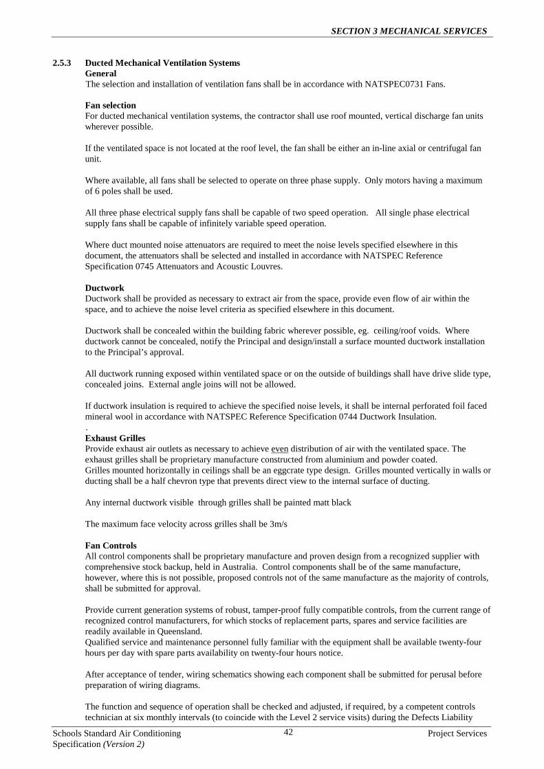
SECTION 3 MECHANICAL SERVICES
Schools Standard Air Conditioning Project Services Specification (Version 2)
42
2.5.3 Ducted Mechanical Ventilation Systems General The selection and installation of ventilation fans shall be in accordance with NATSPEC0731 Fans. Fan selection For ducted mechanical ventilation systems, the contractor shall use roof mounted, vertical discharge fan units wherever possible. If the ventilated space is not located at the roof level, the fan shall be either an in-line axial or centrifugal fan unit. Where available, all fans shall be selected to operate on three phase supply. Only motors having a maximum of 6 poles shall be used. All three phase electrical supply fans shall be capable of two speed operation. All single phase electrical supply fans shall be capable of infinitely variable speed operation. Where duct mounted noise attenuators are required to meet the noise levels specified elsewhere in this document, the attenuators shall be selected and installed in accordance with NATSPEC Reference Specification 0745 Attenuators and Acoustic Louvres. Ductwork Ductwork shall be provided as necessary to extract air from the space, provide even flow of air within the space, and to achieve the noise level criteria as specified elsewhere in this document. Ductwork shall be concealed within the building fabric wherever possible, eg. ceiling/roof voids. Where ductwork cannot be concealed, notify the Principal and design/install a surface mounted ductwork installation to the Principal’s approval. All ductwork running exposed within ventilated space or on the outside of buildings shall have drive slide type, concealed joins. External angle joins will not be allowed. If ductwork insulation is required to achieve the specified noise levels, it shall be internal perforated foil faced mineral wool in accordance with NATSPEC Reference Specification 0744 Ductwork Insulation. . Exhaust Grilles Provide exhaust air outlets as necessary to achieve even distribution of air with the ventilated space. The exhaust grilles shall be proprietary manufacture constructed from aluminium and powder coated. Grilles mounted horizontally in ceilings shall be an eggcrate type design. Grilles mounted vertically in walls or ducting shall be a half chevron type that prevents direct view to the internal surface of ducting. Any internal ductwork visible through grilles shall be painted matt black The maximum face velocity across grilles shall be 3m/s Fan Controls All control components shall be proprietary manufacture and proven design from a recognized supplier with comprehensive stock backup, held in Australia. Control components shall be of the same manufacture, however, where this is not possible, proposed controls not of the same manufacture as the majority of controls, shall be submitted for approval. Provide current generation systems of robust, tamper-proof fully compatible controls, from the current range of recognized control manufacturers, for which stocks of replacement parts, spares and service facilities are readily available in Queensland. Qualified service and maintenance personnel fully familiar with the equipment shall be available twenty-four hours per day with spare parts availability on twenty-four hours notice. After acceptance of tender, wiring schematics showing each component shall be submitted for perusal before preparation of wiring diagrams. The function and sequence of operation shall be checked and adjusted, if required, by a competent controls technician at six monthly intervals (to coincide with the Level 2 service visits) during the Defects Liability

SECTION 3 MECHANICAL SERVICES
Schools Standard Air Conditioning Project Services Specification (Version 2)
43
Period. Include the outcome of each visit in the service report. Each item of control equipment shall be clearly marked by an engraved traffolyte label or other approved means to indicate the function it performs. Provide necessary auxiliary field devices such as local control panels, time switches, etc. and external control cabling as required to interface with the fan units. Controls for can be either 24 or 240 volt. Commission and test all systems. Control Panels For each fan or fans used to ventilate a given space, provide a common control panel that incorporates the following function:
• An ‘ON’ press button. Pressing this button shall, via a 0-8 hour adjustable timer, initiate the operation of
the fan unit/s • An ‘OFF’ press button that will override the ‘ON’ and shut off the fan unit/s • A fan speed control switch. For three phase fans, this shall consist of toggle switch to select fan HI or LO.
For single phase fans, this shall consist of a rotary switch to enable infinite control over fan speed. • A green ‘RUN’ light to indicate mechanical ventilation system operation The above items shall be located in a flush mount panel and engraved to indicate the function of each item. The panel shall be engraved with the title ‘VENTILATION SYSTEM’. Multiple units serving the one space shall be operated via a single controller and shall run together as a single operating system. Any space identified by the Head of Facility as a Double Teaching Area, but does not have a separating concertina partition shall, for the purposes of mechanical ventilation controls, be considered as one individual classroom space. Any space identified by the Head of Facility or in this document as Double Teaching Area but that does have a separating concertina partition shall, for the purposes of Ducted mechanical ventilation controls, be considered as two individual classroom spaces. The exception to this shall be Double Teaching spaces in modular buildings. In this case, unless specifically requested by the Head of Facility, the contractor shall install a control panel for each half of that Double Teaching space. Power Isolator Locate adjacent to each ducted fan unit a lockable isolation switch.
2.5.4 Propellor Type Ventilation fan unit selection and installation General Requirement Where a propeller fan is used the contractor shall supply and install exhaust ventilation fan systems in each room consisting of the following: • Proprietary V-belt and pulley driven propeller fan(s) ‘Cardiffair’ or approved equal; • Proprietary motorised, ceiling mounted exhaust louvre(s); • Proprietary roof mounted louvred air discharge canopy(s); • Interconnecting ductwork between the ceiling mounted exhaust louvre and the roof mounted relief canopy.
The exhaust fan shall be mounted inside the relief canopy. • All wiring and controls as specified below. • All other work necessary for a complete and operative installation. Design Parameters The ventilation systems are to achieve a minimum of 60 Air Changes per hour through each of the ventilated spaces. The selection and number of fans installed in each ventilated space shall be based on each fan being limited to exhausting a maximum 4250 litres/sec. Where exhaust air quantities greater than 4250 litres/sec are

SECTION 3 MECHANICAL SERVICES
Schools Standard Air Conditioning Project Services Specification (Version 2)
44
required then additional fans shall be installed. Fan and Louvre Selection The fans installed shall be proprietary, single phase, V-belt and pulley driven propeller fan units ‘Cardiffair’ or approved equal; For each fan provide a proprietary electrically operated, opening and closing, motorised ceiling exhaust louvre for each installed fan. The motorised louvre shall be supplied by the fan manufacturer. For each fan provide a proprietary roof mounted, weatherproof louvred air discharge canopy supplied by the fan manufacturer. Installation Fans, ceiling mounted motorised louvres and the roof mounted discharge canopy are to be installed in strict accordance with the fan manufacturer’s recommendations. The ceiling mounted exhaust louvres shall be located to achieve the most efficient ‘scavenging’ of air in the room as possible to achieve the maximum cooling effect for occupants. The fan unit shall be installed inside, and at the base of the roof mounted discharge canopy in accordance with the fan manufacturer’s recommendations. All fans must be easily accessible for maintenance either through the rooftop louvred canopy or room ceiling. Provide sheet metal ductwork to achieve a direct exhaust path connection between the ceiling mounted exhaust louvre and the fan intake located at the roof level. The ductwork shall be internally lined with 50mm perforated foil faced mineral wool insulation in accordance with NATSPEC Reference Specification 0744 Ductwork Insulation. All duct connections shall be such that there is no noise breakout from the exhaust path to the roof space. Completely isolate the fan and motorised louvre assemblies from the building structure by means of suitable anti-vibration mounts as recommended by the fan manufacturer. Where the space being ventilated has a raked ceiling, provide a plywood construction set-down below the ceiling such that the ceiling mounted exhaust louvre sits horizontally. The set-down intrusion to the room shall be the minimum that can be achieved to mount the louvre horizontally. If ductwork insulation is required to achieve the specified noise levels, it shall be internal perforated foil faced mineral wool in accordance with NATSPEC Reference Specification 0744 Ductwork Insulation. Controls Each fan shall be individually controlled via wall mounted fan panel that has the following functionality: • An ON/OFF push button. • A rotary control to provide the occupants with infinitely variable fan speed control • A push-button timer control to allow occupants to set fan run times of 2, 4, 6 or 8 hours. • Indicator lights to indicate the selected run time and fan operation. The control panel shall be a proprietary unit supplied by the fan manufacturer. It shall be a flush mount panel similar to adjacent light switches. Each control function on the panel shall be clearly labelled to indicate operation. The control panel shall be fixed to the wall adjacent to light switches serving the room served or as otherwise advised by the Principal. It shall be engraved with wording ‘VENTILATION FAN’ or alternatively, an engraved traffolyte label shall be fixed to the wall above the panel to clearly indicate the purpose of the control panel.
2.5.5 Noise Levels Internal Noise Levels Noise levels in all mechanically ventilated areas shall not exceed NR45. Noise level measurements within the mechanically ventilated areas, shall be taken at 1500mm above the floor level at all areas within the space. Noise levels shall not be measured closer than 1m from any flat surface such walls and ceilings. Internal noise levels in areas adjacent to operating equipment associated with the mechanically ventilated

SECTION 3 MECHANICAL SERVICES
Schools Standard Air Conditioning Project Services Specification (Version 2)
45
installations shall not have noise impingements of levels higher than those listed above for evaporative cooled spaces. External Noise Levels Noise levels at site boundaries shall meet all local Government requirements for the area and the Division of Noise Abatement and Air Pollution Control. Noise levels shall not exceed 40 dBA at site boundaries or within 3 metres of noise sensitive areas of the school site.
2.6 CONSTRUCTION, QUALITY OF WORK AND MATERIALS 2.6.1 General
This section specifies the minimum installation requirements, quality of work and materials to be used for the mechanical services installation. In addition to specific requirement listed below, installations shall comply with all other requirements specified elsewhere in this document.
2.6.2 Authorities’ Approvals Arrange for all inspections required by the relevant authorities at various stages and at completion of the whole installation. Original document evidencing self-certification or approval by the authorities shall be submitted and copies included in the operating and maintenance manuals. Make application for all permits required by each relevant authority and pay all associated fees.
2.6.3 Certification and Approval of Building Works Arrange for all documentation and certification required for the lawful execution of the Builders Work including Building Approvals. Termite Barriers: Where any termite barriers have been broken, the contractor will be responsible to engage a certified pest controller to carryout and repair these areas. These areas include but are not limited to: Installation of underground electrical pipes, drains, condensate drains etc. After the completion of the above, Certification of these works will be provided as part of the as installed manuals.
2.6.4 Fire Stopping Penetrations through any fire-rated barriers shall be sealed with approved fire stopping devices such as fire dampers and packing after installation of ducts, pipes and conduits. Ensure that the integrity of the fire rating is maintained. The whole method of fire sealing shall be in accordance with the requirements of relevant statutory authorities, including the Building Code of Australia, and manufacturer’s recommendations.
2.6.5 Electrical Services In addition to specified requirements for the mechanical services installations in this section of the document, all electrical works shall also comply with the requirements of Section 3 - ELECTRICAL SERVICES of this document. All electrical work shall be carried out by qualified electricians who hold the requisite certificates of competency issued by the Electrical Workers’ and Contractors’ Board of Queensland. The Electrical Contractor shall hold an Electrical Contractors’ License issued by such Board.
2.6.6 Vibration Suppression The contractor shall take all necessary steps to prevent the transmission of vibration and noise from rotating or reciprocating equipment to all building elements. This shall include the support of external equipment such as condensing units, evaporative cooling units and fans located on concrete plinths, galvanised stands or wall brackets. As a minimum this shall include the installation of vibration isolation mountings as follows: Condensing units All condensing units shall as minimum be isolated from mounting surfaces such as concrete plinths, support brackets and sunhoods using 10mm neoprene vibration isolation waffle pad. It is allowable for the waffle pad

SECTION 3 MECHANICAL SERVICES
Schools Standard Air Conditioning Project Services Specification (Version 2)
46
to be drilled for the installation of a suitable fastener required to fix the unit in place. Fan coil units All fan coil units shall be isolated from the support brackets using neoprene vibration isolation waffle pad if necessary to isolate any fan coil unit vibration from the adjacent building structure. Fans Ducted outside air fans shall be supported from the roof structure with galvanised threaded rod and rubber-in-shear vibration isolation mounts. Roof mounted fans shall be isolated from the fan support upstand using neoprene vibration isolation strips if necessary to isolate any fan vibration from the adjacent building structure Wall and window mounted outside air fans shall, as part of the support fixing, include neoprene vibration isolation strips if necessary to isolate any fan vibration from the adjacent building structure. Evaporative Cooling Units All evaporative cooling units shall, as minimum, be isolated from mounting surfaces such as concrete plinths, galvanised stands or wall brackets using 10mm neoprene vibration isolation waffle pad. It is allowable for the waffle pad to be drilled for the installation of a suitable fastener required to fix the unit in place. Installation All mounting supports for equipment shall be arranged to give adequate clearance for free movement of the vibration isolation elements.
2.6.7 Ceiling Insulation Provide ceiling insulation as determined is required at the design stage. All new insulation shall be Bradford R3.0 Polyester or approved equal. Refer air conditioning, evaporative cooling and mechanical ventilation Design sections of this document for insulation requirements.
2.6.8 Location and Installation of Air Conditioning, Evaporative Cooling and Fan Units General The contractor shall liaise with the Principal to determine the location for all equipment. As a minimum, all equipment shall be installed in accordance with manufacturer’s recommendations and all other specified requirements in this document. Ensure compliance with manufacturer’s recommendations on clearances for maintenance and airflow. Fasteners used to fix equipment in place shall allow for easy removal of the units for major maintenance or replacement. Additionally, the location and installation of the equipment shall be in accordance with the following requirements: Fan Coil Units Particular attention shall be taken to the location of under ceiling fan coil units. Such units shall be located with the rear of the unit as close as possible to a wall within the limitations set down by the manufacturer. All fan coil units shall be located to avoid existing lighting and ceiling fans. Under ceiling and in-ceiling cassette fan coil units shall be supported from ceilings, walls or roof structures with certified proprietary galvanised steel support systems. If non-proprietary support systems are used, all such supports shall be designed and certified by a Registered Professional Structural Engineer Queensland (RPEQ). For areas where ceiling cassettes are to be installed and there is insufficient roof space height for installation, the cassettes shall be spaced under the ceiling with a proprietary or custom built spacer (refer photos bound into this document). Condensing Units Wherever possible, condensing units shall be located in a shaded location either under overhanging eaves or on the southern side of the building. All condensing shall be ground mounted unless otherwise authorised by the Principal.

SECTION 3 MECHANICAL SERVICES
Schools Standard Air Conditioning Project Services Specification (Version 2)
47
Locate Condensing units to avoid hot air and noise intrusion to non air-conditioned spaces. Wall or roof mounted condensing units are to be avoided wherever possible. Wall or roof mounting of condensing units will only be allowed if authorised by the Principal. All wall or roof mounted condensing units shall be supported with certified proprietary galvanised steel support systems. If non-proprietary support systems are used, all such supports shall be designed and certified by a Registered Professional Structural Engineer Queensland (RPEQ). All ground mounted condensing units shall be supported on concrete plinths and galvanised steel stools and then housed inside galvanised steel security enclosures in accordance with Standard Drawing WC-2009-M1 bound into this document. The condensing unit support stool shall be fixed to the plinth using stainless steel masonry anchors. All condensing units shall be mounted on vibration isolation waffle pads and fixed in place using stainless steel fasteners. For flood prone areas, condensing units shall be located above flood levels on galvanised steel wall brackets or ground mounted support stands. As noted above any wall mounting of condensing units will only be allowed if authorised by the Principal. The contractor shall be responsible for determining such levels and determining the required location and height above ground level for any support brackets or ground mounted stands. All support stands shall be fixed to a concrete plinth. Stainless steel masonry anchors shall be used to fix stands to plinths. Outside Air Fans Install each fan in accordance with manufacturer’s recommendations and NATSPEC Reference Specification 0731 Fans..
Arrange fans and accessories to allow service access for maintenance and removal and for replacement of assemblies and component parts without disturbance of other items of plant.
Wall mounted fans can be fitted in existing window or louvre openings if the installation of the fan does not reduce natural lighting to unacceptable levels. The contractor shall seek the approval of the Principal before proceeding with such an installation. If this is not acceptable to the Principal, the fan shall be installed in the wall. Fans mounted in window or louvre openings shall be mounted in a suitable fixed pre-finished panel with sufficient strength to support the fan and to maintain the security integrity of the wall. Wall mounted centrifugal outside air fans shall be located to allow easy access to the filter from within the air conditioned space. Removal of the front panel/outlet of the fan to remove the filter element is not acceptable. For ducted fans, provide airtight flexible connections to prevent transmission of vibration to ductwork. If under negative pressure, ensure that fan inlet areas are not reduced. If necessary, provide expansion pieces between fans and flexible connections. Ducted fans shall be in-line backward curved centrifugal or axial. Wall mounted fans shall be centrifugal or axial. Wall mounted axial fans shall only be used for areas with occupancies of less than 7 persons. In general, electrical isolation switches shall not be used for the connection of power supply to wall mounted outside air fans. The power supply for outside air fans shall be via a direct connection to the switchboard from which the power source for the fan is derived. The only exception to the above power connection requirement is where an on-wall fan switch is to be provided for staff-only related areas.
Evaporative Cooling Units The type of evaporative cooling system shall be confirmed with the Principal. All roof-mounted units shall be provided with maintenance platforms, access walkways and ladders all in

SECTION 3 MECHANICAL SERVICES
Schools Standard Air Conditioning Project Services Specification (Version 2)
48
accordance with AS1657. Ground-mounted units shall be mounted on concrete plinths and be housed inside galvanised steel mesh or chainlink fence security enclosures. All enclosures shall be fitted with lockable gates for clear and easy access for maintenance or replacement of equipment. All locks to be keyed alike with other security enclosures on the site. Provide 2 sets of keys. Ground mounted evaporative coolers in flood prone areas, shall be located above flood levels on galvanised steel support stands. The Contractor shall be responsible for determining such levels and advising the building contractor of the required location and height above ground level for the stands. All support stands shall be fixed to a concrete plinth. Stainless steel masonry anchors shall be used to fix stands to plinths. All evaporative coolers shall be mounted on vibration isolation waffle pads and fixed in place using stainless steel fasteners. Mechanical Ventilation Fans Refer Mechanical Ventilation Design Section of this document for further detail on installation requirements for specific mechanical ventilation types.
2.6.9 Equipment Power Isolators Locate adjacent to each air conditioning condensing unit, evaporative cooling unit and ducted fan unit a lockable power isolation switch.
2.6.10 Plinths Provide nominal 100mm thick concrete pads under all ground mounted condensing and evaporative cooling units. Materials and construction to AS3600-1994. Concrete: 20 Mpa to AS1379. Reinforcement: F72 fabric to AS1302.
2.6.11 Ductwork And Diffusers Arrange ductwork neatly. Provide access to ductwork components that require inspection, entry, maintenance and repairs. Where possible, arrange duct runs adjacent and parallel to each other and to building elements. Provide plenum (cushion head) boxes to all diffusers connected to flexible ductwork. Seal all penetrations.
2.6.12 Piping, Valves And Fittings Refrigeration pipework and fittings are to be in accordance with AS/NZS 1571 AND AS/NZS 1677. Insulate all refrigeration suction lines and liquid lines with a minimum thickness of 13mm elastomeric sponge ‘Armaflex’ type insulation. This requirement is additional to any of the air conditioning manufacturer’s requirements and shall be applied in all cases. All insulation is to be installed in strict accordance with the supplier’s recommendations. As a minimum, all joins shall be glued and taped. Under no circumstances shall pre-insulated refrigeration pipework be used for the installations. Any installations found to be fitted with pre-insulated refrigeration pipework will be rejected. Pipe sizing for refrigerant lines shall be established in consultation with the equipment manufacturer. Ensure all refrigeration pipework is adequately supported and secured to the existing structure with proprietary brackets. As a minimum, all refrigeration lines shall be rigidly supported at such spacing to avoid sagging and damage to pipework. Under no circumstances shall support centres be greater than 2m. All condensate lines shall be fixed in place using double-sided galvanized saddles at a maximum centre distance of 600mm.
2.6.13 Drain Lines General Every endeavour shall be made to run air conditioning condensate, evaporative cooling and mechanical ventilation fan drain lines to the nearest storm water or sewerage connection in accordance with the local council authority requirements.

SECTION 3 MECHANICAL SERVICES
Schools Standard Air Conditioning Project Services Specification (Version 2)
49
If no such connection points are readily available, the contractor shall provide of a tundish at the building alignment and an underground drain line to a suitable rubble drainage pits for the collection of condensate. The locations of rubble pits shall be approved by the Principal. As a minimum, rubble pits shall: • be sized to suit the number of AC units being drained and be positioned a minimum of 2000mm clear of
building foundations; • comply with the relevant local government Authority requirements for the design of
transpiration/evaporation septic systems as applicable to the region and suit local ground conditions with respect to percolation rates.
• Comply with the materials and workmanship to AS/NZS 3500. Drain Lines shall not be run into existing vent pipes, down pipes or storm water gutters without prior written approval of the Principal. The discharge of drain water from evaporative coolers or fans direct onto roof sheeting is not acceptable and will be rejected. The discharge end of drain lines shall be fitted with suitable vermin proofing mesh to avoid any obstruction in the line due such things as ant and hornet nests. As a minimum, this proofing shall consist of a stainless steel ‘termimesh’ fixed to the end of the condensate line. The mesh shall be fixed in place such that it is not easily damaged but can be removed for cleaning and inspection of the main drain line. The end of the line onto which the vermin proofing mesh is fitted, shall be oversized by way of a pipe expansion piece such that the free area size of the discharge is not less than that of the main drain line (eg. A 25mm drain line may require expanding to 32mm at the mesh location). Condensate and drain line connections from mechanical services equipment to all drain systems be it sewerage, storm water or a rubble pit shall be via a tundish such as to prevent any backup from the drain system into the air conditioner, evaporative cooler or fan. Wherever possible, the contractor shall provide tundishes at 2100mm above ground level. Tundishes are not to be installed inside air conditioning condensing unit security cages due to potential blockages caused by litter. Provide individual drain lines from each air conditioning fan coil unit, evaporative cooling unit and ventilation fan to the collection tundish. The quantity of drain lines that can drain into one tundish shall be limited to ensure that the system is workable and that the vermin proof fitting installed on the end of each drain line is accessible for removal and cleaning purposes. Where required to avoid mechanical damage, such as mowers and the like, provide mechanical protection around drain lines running between tundishes and ground level. Air Conditioning Condensate Drains Provide 20mm minimum diameter copper or PVC condensate lines from each air conditioning fan coil unit. Larger diameters must be used where recommended by the air conditioning equipment manufacturer. Condensate from under ceiling air-conditioning and wall mount fan coil units is to be drained under gravity. Condensate pumps are not to be used for this type of unit. Where condensate lines run within occupied spaces and above ceilings, insulate with 13mm Armaflex’ or approved equal elastomeric sponge insulation. Evaporative Cooling Unit Drains Evaporative Cooling Unit Drain lines shall be sized in accordance with the manufacturer’s recommendations.
2.6.14 Water Supply The contractor shall provide all water supply pipework and valves necessary for complete and operative evaporative cooling installations. This water supply shall be drawn from existing mains water supplies currently servicing the site. Provide a water supply ball valve isolator adjacent to each evaporative cooling unit. Provide a cold water supply system installed from the meter, or appropriate location, to draw-off points and connections to other services. Water supply provision shall, as a minimum, comply with AS/NZS 3500.

SECTION 3 MECHANICAL SERVICES
Schools Standard Air Conditioning Project Services Specification (Version 2)
50
Submit drawings and schedules showing layout and details of the system, including location, type, grade and finish of piping, fittings, valves, meters and pipe supports, access openings, cover plates, valve boxes and access pits. Test system for leaks. Repair as necessary, replace if damaged and retest. Provide the fittings necessary for the proper functioning of the water supply system including taps, valves, backflow prevention devices, pressure control devices, strainers, gauges and automatic controls and alarms. All fittings to be brass or equivalent approved. All pipework to be copper or equivalent approved.
2.6.15 Access To Services All piped services shall be arranged so as to ensure that access is readily available at all times for joint and insulation inspection, etc. and to facilitate easy replacement of defective equipment, if found necessary, in the future. Access to pipes and valves Service ducts housing piping shall be sized so that valves and pipes for floor runs and in ceiling spaces are concealed with access panels,. Floor run out pipework shall be kept to a minimum. Run out pipework where required shall generally run over corridors, general office areas, and be kept to a minimum over Library and Computer Rooms. Adequate provision shall be made for servicing of all equipment insitu. Access for testing and maintenance Adequate provision shall be made for access to permit testing, servicing and maintaining various system items such as heater protection thermostats/air flow switches, duct mounted return air thermostats, air handling system dampers etc. whether located in plant rooms, duct risers or in above ceiling spaces.
2.6.16 Piping And Electrical Line Runs All refrigeration and electrical lines located under floors shall be run parallel and be fixed to the floor structure. All lines shall be securely fixed with proprietary fasteners and be arranged neatly.
2.6.17 Pipework And Electrical Cabling Covers All pipework and electrical cables, external and internal that are exposed to view, damage or direct sunlight shall be covered with galvabond or colorbond steel metal covers. This shall include all pipework and electrical cables that are run under the floor structure of buildings. If galvabond covers are used, visible surfaces must be painted to match adjacent building colours. All visible surfaces of Colourbond covers must match adjacent building colours or be treated with a topcoat colour to match. The sheet metal covers shall take the form of a backing channel section for housing and supporting the services and a screw fixed front cover that is easily removal by service personnel for access to inspect and repair pipework and electrical cabling. All sheet metals covers shall be professionally fabricated with lapped and mitred corners and free of any sharp edges and burrs. Under no circumstances shall PVC pipework covers be used. Seal all penetrations
2.6.18 Electrical Cabling Conduit Under no circumstances shall corrugated flexible electrical conduit be used. All electrical conduit shall be rigid PVC.
2.6.19 Relocation Of Existing Services The Contractor shall relocate all existing services such as lights, fire detectors, security sensors and any other electrical fitting that clash with air conditioning unit locations or that hinders correct operation of the air conditioning or the existing services
2.6.20 Painting All painting carried out by the contractor shall be undertaken in accordance with NATSPEC Reference Specification 0701 General Requirements (Mechanical).

SECTION 3 MECHANICAL SERVICES
Schools Standard Air Conditioning Project Services Specification (Version 2)
51
All external and internal services exposed to view are to be painted. This shall include all drain lines, exposed electrical conduits and sheet metal covers not run in colorbond.
Colours shall be to match adjacent colour schemes. All internal ducting visible through grilles shall be painted matt black.
2.6.21 Marking General Mark equipment, electrical wiring, piping, valves, conduits and ducts so that they are readily identifiable. This shall include the air conditioning unit number on both the condensing and fan coil units. All condensing and fan coil units must be labelled with the date of commissioning. Piping, conduits and ducts: to AS 1345, as applicable. Labels Type: Select from the following
• Engraved and black filled lettering on stainless steel or brass, at least 1 mm thick • Cast metal • Engraved two-colour laminated plastic for indoor applications only.
Label edges: If labels exceed 1.5mm thickness, use radiused or bevelled edges. Minimum lettering heights Equipment name plates (except fan coil units): 40mm. Fan coil units: 25mm. Date of commissioning: 7mm. Warning notices: 7mm. Automatic controls and electrical equipment: 5 mm. Isolating switches: 5 mm. Inside electrical enclosures: 3.5mm. Other: 3 mm.
2.6.22 Roof And Wall Penetrations Provide all roof penetrations, wall penetrations and flashed upstands as necessary for the installation and support of the mechanical services. Provide all trimming, strengthening of roof and wall structures as necessary. All trimming and modifications to structural walls and roof members shall be certified by Registered Professional Structural Engineer Queensland (RPEQ). All penetrations shall be weatherproofed as specified elsewhere in this document.
2.6.23 Flashing and Capping of Penetrations Provide flashings and cappings for all roof and exposed wall penetrations. Flashing material to AS/NZS 2904. Pre-form to required shapes where possible. Notch, scribe, flute or dress down as necessary to follow the profile of adjacent surfaces. Mitre angles and lap joints 150 mm. Flash projections above or through the roof with two part flashings, consisting of a base flashing and a cover flashing, with at least 100mm overlap. Provide for independent movement between the roof and the projection. Flash pipes by sealing with neutral cured silicone rubber and provision of a proprietary flexible clamping shoe with attached metal surround flashing.
2.6.24 Access Panels Provide Access Panels as required through flush ceilings and bulkheads. Material to match adjacent ceiling/bulkhead. Provide perimeter trim to Access Panel and adjacent ceiling/bulkhead. Provide Access Panel support and screw fixings to facilitate regular maintenance access.

SECTION 3 MECHANICAL SERVICES
Schools Standard Air Conditioning Project Services Specification (Version 2)
52
Where in-ceiling cassettes are located in fixed panel ceilings such as plasterboard, provide ceiling access panels to allow easy maintenance of the fan coil.
2.6.25 Termite Barriers And Protection It is the Contractor’s responsibility to provide termite protection where the termite barriers have been disturbed. Certification will be required for this work and carried out by a qualified and registered business for the protection of termites. Provide the certificate in the air conditioning manuals. The protection will be required where underground pipes are run up the exterior or interior of buildings. These will be electrical, mechanical, water, condensate lines and drains etc
2.6.26 Roof Access For each roof mounted evaporative cooling unit provide roof access walkways, ladders, handrails and a nominal 600mm maintenance platform adjacent to the unit.

SECTION 3 MECHANICAL SERVICES
Schools Standard Air Conditioning Project Services Specification (Version 2)
53
2.6.27 Standard Drawings The following pages contain standard drawings that apply to the construction and installation of the mechanical services as specified elsewhere in this document.

SECTION 3 MECHANICAL SERVICES
Schools Standard Air Conditioning Project Services Specification (Version 2)
54

SECTION 3 MECHANICAL SERVICES
Schools Standard Air Conditioning Project Services Specification (Version 2)
55
2.6.28 Typical Installation Quality And Configuration Following are photos showing the installation standard and work quality required as well as the typical configuration for some of the major components to be installed. The photos show the minimum standard that will be expected. Any installation of a lesser standard will be rejected and replaced to meet that shown in the photos.
TYPICAL CONDENSING UNIT MOUNTING AND ENCLOSURES

SECTION 3 MECHANICAL SERVICES
Schools Standard Air Conditioning Project Services Specification (Version 2)
56
TYPICAL FAN COIL UNIT INSTALLATIONS
TYPICAL OUTSIDE AIR FAN INSTALLATIONS
TYPICAL CONTROLS

SECTION 3 MECHANICAL SERVICES
Schools Standard Air Conditioning Project Services Specification (Version 2)
57
TYPICAL EVAPORATIVE COOLING INSTALLATIONS

SECTION 3 MECHANICAL SERVICES
Schools Standard Air Conditioning Project Services Specification (Version 2)
58
OAF in louvre gallery with bird proof hood
Pipework panel for entry to building & drain access
OAF labels & connection
Tundish & drains with vermin proof cap
OAF cut into wall

SECTION 3 MECHANICAL SERVICES
Schools Standard Air Conditioning Project Services Specification (Version 2)
59
2.7 COMMISSIONING 2.7.1 General
Acceptance of Practical Completion and of Final Completion shall require the Contractor to demonstrate that the system meets the intent of the design. Individual written approval must support any and each deviation from the proposed design concept and design criteria.
Include the requirements recommended by equipment manufacturer.
Requirement For each required test, provide a report or certificate in a form suitable for inclusion in an operation and maintenance manual, signed and dated, legibly typed or printed recording: • the type of test;
• the test procedures;
• the apparatus and instruments used;
• the date, time and place of the test;
• the ambient and other relevant conditions;
• the name, status, function and signature of each person present;
• the test results;
• where applicable, calculations, instrument readings, control settings, name plate ratings, and the like;
• Variations to the specification, if any.
Testing and Commissioning methods Submit for approval, proposed methods for testing and commissioning of all equipment.
2.7.2 Completion
Commissioning When the installation is complete, commission the installation by putting it into working order and operating it for not less than the designated time controlled period (ie 2 or 8 hour operation). For proprietary control installations the commissioning period shall be a minimum of 2 hours. Make the adjustments necessary to achieve the designated performance under continuous operating service conditions, including balancing, setting the controls, and checking the operation of overload and safety devices, and correcting malfunctions. All commissioning tests shall be carried out with all equipment in its fully operational state. This shall include all outside fans and time clock controls. In addition to the specific commissioning requirements of this document, the commissioning requirements of the relevant Natspec Reference Specification shall also apply. Supply and Exhaust air balancing Adjust all air-handling systems to give flow rates within +/-10% of design air quantities, subject to the following: • Distribution: Distribute air to minimise draughts.
• Fans: Adjust fans to run at lowest fan speeds and power consumption and with minimum resistance to meet the design quantities.

SECTION 3 MECHANICAL SERVICES
Schools Standard Air Conditioning Project Services Specification (Version 2)
60
• Filters: All filters must be clean prior to final commissioning tests.
The contractor shall also carry out simulated dirty filter tests. This test shall simulate a condition equal to the mean and of the initial and final resistance of the filter bank. At this condition the air quantities must not be below that of the design air quantity.
• Evaporative Pads: All evaporative pads must be clean prior to final commissioning tests.
The contractor shall also carry out simulated evaporative pad tests. This test shall simulate a condition equal to the mean and of the initial and final resistance of the evaporative pads. At this condition the air quantities must not be below that of the design air quantity.
Multiple Systems If there are multiple inter-related air handling systems, all systems shall operate concurrently. Dampers Mark final position of dampers when balancing is complete.
Reports Include on the commissioning data sheets the design and actual air quantities. In addition to other commissioning data specified to be provided, the reports shall clearly identify the Building and Room served by each air conditioning unit, outside air fan, evaporative cooling unit and mechanical ventilation fan. This information shall be presented in a spreadsheet format and clearly identify the Make, Model and Serial Number of each air conditioning fan coil, condensing unit, evaporative cooling unit, mechanical ventilation fan and the rooms served by those units. The spreadsheet shall also include the Make and Model of each outside air fan installed in each room. This information shall be included in the Maintenance and Operations manuals as specified elsewhere in this document. The above information is critical in clarifying warranty claims and is a specific request by the equipment suppliers. It is also required by DET as an accurate asset register of the equipment installed. If at any time during the defects period a ‘hot swap’ is carried out to replace faulty equipment then all records of the Make, Model and Serial Number of the equipment shall be updated. Practical Completion Acceptance Tests Undertake a fully functional trial of the installed equipment prior to practical completion. At this test the contractor shall demonstrate, to the Principal’s satisfaction, that the installation has reached the fully functional design requirements of the specification. The contractor shall give the Principal 2 weeks written notice of the test date. The basis for acceptance of the mechanical services installation shall be that all equipment and systems meet the system performance requirements specified and that the systems have operated satisfactorily in normal operating mode for 5 consecutive working days. These requirements must be met before the Certificate of Practical Completion will be issued. The functional trial will be required to demonstrate stable, safe, reliable operation of the installed equipment through the whole range of plant operation. Supply all labour and test equipment for the trial and, if necessary, coordinate with specialist subcontractors to attend after normal working hours to carry out the trial. If the trial proves unsatisfactory, rectify all faulty work and repeat the trial without contract price variation. The Contractor's costs for repeating failed tests shall, if requested by the Principal, include the cost of the Principal's time and expenses for attending the repeated test. Cleaning At practical completion, clean the following: • Switchgear and contactors, and other electrical contacts. Adjust as necessary. • Strainers. • Air filters: Replace if the resistance exceeds the mean of the initial and final resistance of the filter bank.

SECTION 3 MECHANICAL SERVICES
Schools Standard Air Conditioning Project Services Specification (Version 2)
61
• Evaporative pads. Replace if the resistance exceeds the mean of the initial and final resistance of the evaporative pads.
2.8 SERVICE AND MAINTENANCE 2.8.1 General
During the Defects Liability Period carry out periodic service and maintenance inspections as scheduled below and as recommended by equipment manufacturers. Submit details of service and maintenance procedures and program six weeks before Practical Completion. It is a particular requirement that the Contractor respond promptly to problems as reported by the end-users. If required, the Contractor shall arrange for a hot swap of faulty air conditioning units or fans within 5 working days of being notified.
2.8.2 SERVICE AND MAINTENANCE VISITS
The contractor shall carry out, as a minimum, three and six monthly service and maintenance visits to ensure continued reliable operation of the installation. These visits shall include, but not limited to, the following: Level 1 Service (3 monthly): • Service all air conditioning equipment as required by the equipment manufacturer.
• Service all evaporative cooling equipment as required by the equipment manufacturer and AS3666.
• Inspect operation of outside air supply systems. Rectify any faults.
• Inspect operation of mechanical ventilation systems. Rectify any faults.
• Inspect all drain trays and lines and rectify any leaks or blockages.
• Clean all filters.
• Clean all evaporative pads.
• Address any concerns by the school regarding controls, noise levels and general operation of the installation.
Level 2 Service (6 monthly): • Service all air conditioning equipment as required by the equipment manufacturer.
• Service all evaporative cooling equipment as required by the equipment manufacturer and AS3666.
• Service all outside air and mechanical ventilation fans as required by the fan manufacturer.
• Inspect operation of outside air supply systems. Rectify any faults.
• Inspect all drain trays and lines and rectify any leaks or blockages.
• Clean all filters.
• Clean all evaporative pads.
• Address any concerns by the school regarding controls, noise levels and general operation of the installation.
• Check all items of equipment for operation, calibration, performance compliance, temperature and energy consumption, and record values.
• Check motors and machinery for excessive operating temperature, bearing noise and excessive vibration.
• Check anti-vibration supports, brackets and clamps, holding down bolts and flexible connections, for deterioration and for freedom of movement of assembly.
• Check condition of insulation, and repair if damaged.
• Check electrical and control systems, including safety limits for temperature and pressure.
• Record readings of thermometers, gauges, meters, current draw of motors and heaters, control set points and controlled space conditions.
• Check refrigeration systems for temperature, pressure and gas tightness. Rectify any gas leaks and recharge refrigerant system as necessary.
• Replace faulty and damaged parts.

SECTION 3 MECHANICAL SERVICES
Schools Standard Air Conditioning Project Services Specification (Version 2)
62
Additional service visits In addition to the minimum service visits schedule above, the contractor shall carry out any additional service visits necessary to ensure the equipment manufacturer’s warranty is maintained. This may occur in such cases as schools located in dusty locations, necessitating more frequent filter cleaning. The contractor shall clarify with equipment manufacturer manufacturers the situations where additional service visits are required.
Final Completion Service (end of defects period) Immediately before the end of the twelve months defects period, carry out a Level 2 service. The contractor shall give the Principal 2 weeks notice of the end of defects service so that a final inspection can be held concurrently. NOTE: The air conditioning units supplied by the Principal and/or Contractor have a five-year warranty. In order that this warranty remains valid, regular component servicing and maintenance of the air conditioning equipment must be continued beyond the final completion date in accordance with the manufacturer’s requirements. Two weeks prior to the end of the defects period, the contractor shall advise the Principal of this requirement. It shall be the Principal’s responsibility to arrange for continuing maintenance beyond the final completion date. Service and maintenance records Submit in binders which match the manuals, loose leaf leg book pages designed for recording completion activities including operational and maintenance procedures, materials used, test results, comments for future maintenance actions and notes covering the condition of the installation. Include completed logbook pages recording the operational and maintenance activities performed up to the time of practical completion. Certificates: Include test and approval certificates. Service and breakdown visits: Record comments on the functioning of the system, work carried out, items requiring corrective action, adjustments made and name of service operator. Obtain the signature of the Principal’s designated representative. Referenced documents: If referenced documents or technical sections require that log books or records be submitted, include this material in the maintenance records. Certification: On satisfactory completion of the installation, submit certificates stating that each installation is operating correctly.
2.9 SHOP DRAWINGS The contractor shall produce workshop drawings prior to commencement of installation and manufacture of any components or ductwork necessary for completion of the works and coordination with other trades such as building and electrical works. All drawings shall be submitted to the Principal for information only. The drawings shall be signed by the Contractor’s responsible officer. Drawings requiring approval shall also be forwarded to any relevant regulatory authorities. • The drawings shall include, but not limited to the following:
Arrangement drawings showing size, location and height or depth of all air conditioning fan coils, condensing units, evaporative cooling units, piped services, electrical cables and ductwork. Particularly show the size and fully dimensioned locations of all penetrations.
• Details of working platforms including method of support. • Details of all condensing unit, fan coil, evaporative cooling unit and mechanical ventilation support
brackets, platforms and fixing details. A structural certificate, issued by shall by an engineer registered, as professional engineer in Queensland (RPEQ), shall accompany all such drawings. The engineer shall certify that all components are structurally sound. NOTE: It is the contractor’s responsibility to provide all structural steel work necessary for the support of mechanical services equipment. This work shall include all design and structural certification as required.
• Layouts and sections of all plant and equipment including ductwork and pipework and associated
supports.

SECTION 3 MECHANICAL SERVICES
Schools Standard Air Conditioning Project Services Specification (Version 2)
63
• Power and control circuit wiring diagrams of all plant. This shall include dimensioned arrangement of control panels. Such diagrams shall clearly indicate the function of each item of equipment.
• Where packaged equipment is supplied, include the manufacturer’s standard circuit diagram, modified to
comply with the specified system and control requirements. Should the modifications require the provision of an additional control board or cabinet, a dimensioned arrangement, including equipment layout, of such board or cabinet shall be included.
All drawings shall be done on AutoCAD Release 2004 (minimum) only use reduction scales 1:20, 1:50, 1:100 or multiples of 10 of these SCALES. All lettering shall be a minimum 3.5 mm high and complying with AS 1100 ‘Technical drawing Part 101 (1992) – General principles suitable for microfilming’. The Autocad drawing files shall be accompanied with Adobe Acrobat Version 8 plot files of all drawings to allow viewing by persons without access to AutoCAD. The examination of shop drawings by the Principal shall not remove the responsibility for the correctness of the dimensions of such drawings not conforming strictly to the requirements of this specification nor compliance with statutory regulations.
2.10 OPERATION AND MAINTENANCE MANUAL Provision of Operation and Maintenance Manual shall be in accordance with section 6 – Operation and Maintenance manual of this Specification.

SECTION 3 MECHANICAL SERVICES
Schools Standard Air Conditioning Project Services Specification (Version 2)
64
THIS PAGE INTENTIONALLY LEFT BLANK

SECTION 4 ELECTRICAL SERVICES
Schools Standard Air Conditioning Project Services Specification (Version 2)
65
SECTION 4 – ELECTRICAL SERVICES
1 GENERAL
1.1 SCOPE OF THIS SECTION Outline Description This section specifies the minimum requirements for the design and installation of electrical services for this contact. Provision of electrical services must comply with the requirements of AS/NZS 3000 (the Australia / New Zealand Wiring Rules), all applicable mandatory codes and statutory requirements, and any Australia / New Zealand (AS/NZS) standards applicable to the works being provided. Refer also to the project-specific documentation, to determine the full extent of electrical services work under the Contract. The completed electrical services must be fit for purpose, fully working, suitable for a vandal prone school environment, and be to the satisfaction of the Principal.
1.2 DESIGN WORK – BY RPEQ The Contractor is to have the design and documentation of any electrical upgrade required, prepared by an electrical engineer registered in Queensland (RPEQ). The finished installation must also be inspected and certified by an electrical engineer registered in Queensland.
1.3 REFERENCED DOCUMENTS Current editions Use referenced documents which are editions, with amendments, current three months before the contract award date, except where other editions or amendments are required by statutory authorities.
1.4 INTERPRETATION General Unless the context otherwise requires, the following definitions apply: • Supply: ’Supply’, ‘furnish’ and similar expressions mean ‘supply only’. • Install: ‘Install’, ‘fix’ and similar expressions mean ‘install only’. • Provide: ‘Provide’ and similar expressions mean ‘supply and install’. • Proprietary: ‘Proprietary’ mean identifiable by naming manufacturer, supplier, installer, trade name,
brand name, catalogue or reference number. • Samples: Includes samples, prototypes and sample panels. Abbreviations AS: Australian Standards. BCA: Building Code of Australia MSB: Main Switchboard DSB: Distribution Switchboard RCD: Residual Current Device ELCB: Earth Leakage Circuit Breaker
1.5 COMPLIANCE WITH STATUTORY REQUIREMENTS AND STANDARDS General All electrical work shall be performed by:
- Qualified electrical workers holding the required certificate of competency appropriate to the work (e.g. electrical mechanic, electrical fitter, electrical linesman, electrical jointer) issued by the Electrical Safety Office, Queensland.

SECTION 4 ELECTRICAL SERVICES
Schools Standard Air Conditioning Project Services Specification (Version 2)
66
- Probationer, apprentice electrical worker or "improver" working under immediate supervision and direction of an appropriate electrical worker/tradesman.
- The person or firm responsible for the electrical installation work shall hold an Electrical Contractor's License issued by the Electrical Safety Office.
Acts, Codes and Standards Electrical Services shall be designed and installed in accordance with all Acts, Codes and Government Legislation relevant to this type of installation. The following are applicable:
- Building Code of Australia
- AS/NZS – 3000:2007
- AS/NZS 3008.1.1
- Degrees of protection (IP code): AS/NZS 60529
- EMC: AS/NZS 61000
- Other: as nominated in the respective parts of this specification.
Statutory Requirements Without limiting the Contractor’s obligations under other paragraphs the Contractor is to:
- make all applications for approvals and give all notices required to comply with statutory requirements;
- when requested by the Principal, provide a copy of any documents or records and any other information used or relied upon by the Contractor to prepare the application or notice;
- inform the Principal in writing of the requirements or conditions proposed by any authority in relation to the giving of an approval or consent and obtain the written permission of the Principal before agreeing to those requirements and conditions;
- If, in the Contractor’s opinion, any provision of requirement of the Contract is at variance with statutory requirements or the requirements of an order of a court or authority the Contractor is to immediately notify the Principal in writing. The notification is to contain detailed particulars of:
- the provision or requirement which is at variance with statutory requirements or the order; and
- the amendment or modification of the provision or requirements recommended by the Contractor to comply with statutory requirements or the order.
The Principal may direct the Contractor as to the course of action to be taken to ensure that statutory requirements are complied with in the execution of the Works. Statutory authorities Comply with the relevant requirements of the following authorities: - Local Council
- Electrical supply authority
- Department for Industrial Affairs
- Occupation Health, Safety and Welfare Regulations
- Land Services (Department of Environment and Natural Resource)
- Australian Communications Authority
- Fire service authority

SECTION 4 ELECTRICAL SERVICES
Schools Standard Air Conditioning Project Services Specification (Version 2)
67
1.6 ELECTRICAL SERVICES AND BUILDING ACT FORM 16 CERTIFICATION Requirement Provide a certificate stating the completed electrical installation has been tested and found to comply with AS/NZS 3000 and any other specified or applicable standards, and the Electricity Regulations. Certificates from installers licensed by the Electrical Safety Office Provide also Form 16 licensee aspect certificates for the completed electrical installation, referring to the electrical safety, power supply, and protection.
1.7 ASBESTOS-CONTAINING MATERIAL (ACM) General Refer to and comply with the requirements detailed in the ASBESTOS-CONTAINING MATERIAL (ACM) clause in the ‘PRELIMINARIES section of this specification.
1.8 DESIGN, DOCUMENTATION AND INSTALLATION The contractor is responsible for all design, documentation and installation of the complete electrical installation as necessary in accordance with the minimum requirements nominated. This may also include electrical upgrading work. The work includes but is not limited to the following :
• Assessment at tender time the extent of any electrical upgrading required and making the necessary
allowances. In particular for details, refer to the following clause titled ‘ELECTRICAL UPGRADES – PARTICULAR DESIGN REQUIREMENTS’.
• Arranging with the Supply Authority for any upgrade required to the electrical power supply entering the site.
• Design, documentation and installation of any electrical upgrading works required within the site in order
to accommodate the specified new air-conditioning. This includes any upgrades required to the consumers mains, main switchboard, submains and distribution switchboards.
• Design, documentation and installation of all new submains, conduits and distribution switchboards
required. • Design, documentation and installation of all sub-circuits required by the new air-conditioning (and
associated items), and selection of subcircuit cables for each item to provide a current carrying capacity not less than the rated current of the item, and a voltage drop not exceeding the maximum allowed. Provide separate sub-circuits to each new air-conditioner. Provide also power circuits to all new fan units being installed.
• Evaluation of the prospective fault current at each distribution switchboard, and selection of the over
current protection in each functional unit to ensure adequate discrimination and cascading as required to provide overload and short circuit protection of the new and existing sections of the installation.
• The calculation of fault-loop impedance for all new circuits to comply with the requirements of
AS/NZS3000:2007.
• Provision of ceiling fans (or wall fans if necessary) to areas being air-conditioned that do not currently have fans installed. Ensure each teaching area has at least four fans. The location of ceiling fans is to be correctly coordinated with lighting to avoid strobing and is to be approved by the Head of Facility.
• Isolation and removal of all electrical cabling and controls associated with any Evaporative Coolers which
are to be removed.
• Provision of RCD protection as specified, to all new circuits on existing switchboards, and all existing and new circuits required to be connected to any new or replacement switchboards. Refer to the Clause titled RCD (EARTH-LEAKAGE) PROTECTION.
• Removal of any existing bar heaters, in areas which are to be served by reverse cycle air conditioning

SECTION 4 ELECTRICAL SERVICES
Schools Standard Air Conditioning Project Services Specification (Version 2)
68
systems, are to be removed along with all associated fixings, supports, electrical wiring and controls. The salvaged bar heaters shall be cleaned and handed over to the Head of Facility.
• Design of a cable support system to provide the required strength and space for the required cabling and
any proposed known future cabling that will be required to run along the various routes. • Site measurement, setting out, detailed dimensional design and documentation of the Works to ensure the
installation suits the requirements of the School. • Drawings for the site electrical services including the technical data provided in this specification and
details of the site conditions: - Site plans of underground services reticulation and switchboard locations. - Switchboard layouts and shop drawings. - Single line diagrams of the distribution system.
• Submission to the Principal, the certificates of compliance and test records. • Provision of statutory approvals and licences, and payment of levies necessary for the works. (Except for
supply authority charges for any upgrade the incoming electricity supply). • Provision of as built drawings including block diagrams, cable schedules and layouts of equipment. • QA documentation as required. • Operation and maintenance manuals including electrical (RPEQ signed) ‘as installed’ drawings. • Servicing and maintenance of the installation after practical completion including rectification of any
defects throughout the specified defected liability period. • Provision of adequate training to the facility nominated operators to ensure effective and efficient
operation of all equipment provided to the satisfaction of the Principal.
1.9 ELECTRICAL UPGRADES – PARTICULAR DESIGN REQUIREMENTS
Electrical Upgrades required may include the power supply to the site, the consumers mains cables that run from the point of supply to the main switchboard, the main switchboard (MSB), the submain cables that run from the main switchboard to distribution switchboards in the various blocks, and the distribution switchboards (DSB’s). Electrical upgrading may carried out by either increasing the capacity of existing electrical items (size, current rating etc) if those items are in good condition, or by providing new replacement items of the required capacity. The Contractor must assess at tender time whether the electrical supply to the site or any part of the electrical reticulation within the site, needs upgrading in order to cater for the proposed air-conditioning. IMPORTANT - Provide at tender time, details on the extent of electrical upgrading allowed for and also advise the amount allowed for that component of the work. Any new or upgraded power supply to the site, consumers mains, main switchboard, or submains must be sized to cater for the existing loads (that will remain) and the new air-conditioning loads, plus any planned and budgeted future load increases, such as future air-conditioning, and have at least an additional 30% spare capacity. For any building that is to be fitted with new air conditioning that requires it’s submains or distribution switchboard upgraded, allow for the future full air-conditioning of that Block, plus 30% spare capacity. For preliminary load estimates assume that the air-conditioning will require 175 Watts electrical power per square metre of air-conditioned floor area. If the Supply Authority electrical supply to the site requires upgrading then :

SECTION 4 ELECTRICAL SERVICES
Schools Standard Air Conditioning Project Services Specification (Version 2)
69
- At the very start of the Contract, contact the Supply Authority and arrange for the required upgrade to occur. If signatures are required by the School, then forward those completed forms to the Project Manager, to obtain the signatures.
- During the contract arrange for the school to contact their Energy Retailer and request that the electrical
upgrade occur. Give all necessary assistance, information and guidance to the school in carrying this out. - Take all action necessary to ensure that the upgraded power supply is available in a timely fashion and
before it is actually needed to supply the proposed new electrical loads. - Pay all associated Supply Authority charges for the electricity service changes and connections within the
school site. - Any supply authority capital contributions required for electrical upgrading outside the site, or the
provision of a padmount transformer, will be paid for by the school. Advise the school of the expected costs (if any) as early as possible, with at least estimates provided at tender time.
- Upon completion of the project, any new main switchboard must have enough spare poles to cater for any planned and budgeted future Blocks or other loads planned to be connected, plus at least 30% spare pole capacity. As a minimum there must be at least 15 spare poles on completion of the project.
The requirement for any new Distribution Switchboard includes the following : - The Switchboards shall be Project Services Type ‘D’ or ‘B’ distribution switchboards, unless otherwise
indicated. Project Services Type ‘A’ and “E’ Load-centre switchboards are normally only to be used in small Blocks such as sheds or Amenities.
- Provide also any necessary additional protection from likely future high fault currents that will be possible
when the site is fully developed.
- Upon completion of the project, any new distribution switchboard must have the current rating and spare poles to cater for future full air-conditioning of the respective Block, plus at least 30% spare capacity. As a minimum there must be at least 15 spare poles on completion of the project.
The requirement for any new electrical conduits and pits includes the following : - All underground electrical conduits shall be heavy duty underground orange PVC type. - Allow for any planned and budgeted future work when sizing conduits. As a minimum allow 30% spare
capacity. - Allow spare space in new underground conduits such that they can accommodate the expected cables to
all planned and budgeted future Blocks (whose cables are expected to run along the same route), the existing (remaining) cabling, the new cabling, and any other known proposed future increases in cabling, plus at least 30% spare capacity.
- Any new underground conduits for consumers mains must have at least 100% spare capacity. - Electrical conduits run between pits and containing consumer’s mains or submains, shall be at either
150mm or 100mm diameter type. - Provide pits in conduit runs at least every 50 metres and at changes in directions. Run conduits in straight
lines between pits. - Underground conduits must avoid running through the location of future permanent buildings, unless the
finished ground levels and locations of future buildings has already been determined and fixed. Contact the Head of Facility for information on known future building locations. The Head of Facility will then liaise with the school’s Facilities Account Manager to obtain the relevant information.

SECTION 4 ELECTRICAL SERVICES
Schools Standard Air Conditioning Project Services Specification (Version 2)
70
2 ELECTRICAL INSTALLATION
2.1 AS CONSTRUCTED DRAWINGS Requirement Prepare progressively throughout the Works, and furnish to the Principal before the Date for Practical Completion, 'as-constructed' drawings of the electrical installation, to the same scales and on the same sized standard sheets as the Contract Drawings. Provide these drawings in AutoCAD 2009 format, unless otherwise indicated.
2.2 COMPLETION TESTS General Test the works under the contract to demonstrate compliance with the documented performance requirements. Give notice of at least 5 working days so that the Principal and, where applicable, the authorised representative of the relevant Regulatory Authority, may attend and inspect testing required by the Contract. State the date, time and place of the test. If the Principal is unable to attend a test because of insufficient notice, he may order the test to be repeated at the Contractor's cost. Functional checks Carry out functional and operational checks on energised equipment and circuits and make final adjustments for the correct operation of safety devices and control functions. Site testing Include the following tests: - Insulation resistance measurements on motors and major medium voltage equipment items, at 1000 V
DC, and on cables and wiring to AS/NZS 3000;
- Functional checks: Full functional and operational checks on energized control equipment and circuits, including adjustments for the correct operation of safety devices;
- Motor rotation: Checking and where necessary, altering connection for the correct motor rotation;
- Earth resistance measurement: To AS/NZS 3000;
- Earthing: Confirmation of effective earthing of the exposed metal of electrical equipment.
2.3 OPERATIONAL MAINTENANCE Maintenance period Co-extensive with the Defects Liability Period. Requirement During the maintenance period: - Carry out periodic inspections and perform maintenance work at the frequencies and following the
procedures recommended by the manufacturers of the supplied equipment (except for maintenance work specified to be performed by the Principal).
- Promptly rectify faults. Replace faulty materials and equipment and accessories.
Minimum number of visits One every 3 calendar months. Certification At the end of the maintenance period make a final service visit and, upon satisfactory completion of the above procedures, certify in writing that the installation is operating correctly.
2.4 MANUALS Requirement Before commencement of operational maintenance, provide to the Principal the specified number of copies of a combined operator's manual and technical manual, written in clear concise English, containing a title page listing suppliers' names, addresses and telephone numbers, a table of contents, and the following data: - Safe working procedures for switching and isolating the supply and distribution system;
- Information for the satisfactory long-term operation and maintenance of the installation;

SECTION 4 ELECTRICAL SERVICES
Schools Standard Air Conditioning Project Services Specification (Version 2)
71
- Recommended maintenance periods and procedures;
- Particulars of maintenance equipment and tools provided, with instructions for their use.
- Copies of all test results and specified certificates.
- As-Constructed drawings, A3 size (reduced) paper copies, plus DVD electronic copy.
- A technical description of the equipment supplied, with diagrams and illustrations where appropriate.
- Where necessary, procedures for dismantling and re-assembling equipment.
Form A4 size, machine printed or typed on durable printing paper, with each page consecutively numbered, and neatly bound in durable vinyl or similar hard covers. Number of Copies: Unless otherwise indicated, provide four copies.
2.5 SETTING OUT OF RETICULATION
Cable routes Determine the final routes to suit the building structure or site conditions. Obtain approval for the final routes from the Principal prior to installing consumers mains and submains.
2.6 TRENCHING Laying program Excavate trenches in sections of suitable length, lay and bed the relevant service length and backfill the trench section, with the minimum of delay and if possible on the same working day, unless otherwise specified or permitted. Existing surfaces Saw cut existing concrete or bitumen surfaces in a straight line to a minimum depth of 75 mm before excavation is commenced. Lift and store paving slabs for later reinstatement. Excavation After excavation, clear trenches of sharp projections. Depth: - Supply cables: 600 mm.
- Communication Cables: 500 mm.
- Rocky Ground: Agree installation depth with Principal.
Excavations beyond site boundary Notify, and obtain approval from, the appropriate owner before excavation commences. Carry out the excavation to the owner's requirements. Reinstate the surface to match existing.
2.7 CABLE IN TRENCHES Draw cords Provide polypropylene draw cords in conduits not in use. Sand Provide clean sharp sand around cables and conduits installed underground. Under roadways Under roadways and areas subject to traffic movement, install cables in a duct or conduit extending to not less than 1 metre on either side of the sealed surface or trafficable area and encase in concrete having a minimum cover thickness of 100 mm. Concrete Strength: 25 MPa. Sealing ducts and conduits Seal the buried entries to ducts and conduits with a pliable non-setting waterproof compound. Seal spare ducts or conduits immediately after installation, and seal the others after the cable installation.

SECTION 4 ELECTRICAL SERVICES
Schools Standard Air Conditioning Project Services Specification (Version 2)
72
2.8 BORING Subcontractor If under road boring is required in lieu of trenches, engage a suitably qualified subcontractor to do the work. Process Ensure a tight fit to the service pipes. If voids are encountered, fill by pressure grouting.
2.9 BACKFILLING
General Backfill service trenches as soon as possible after the service has been laid and bedded, if possible on the same working day. Place the backfill in layers ≤ 150 mm thick and compact to the required density. Marking services Underground marking tape: To AS/NZS 2648.1. Backfill material General: General fill with no stones greater than 25 mm occurring within 150 mm of the service, or other materials as required for particular services or locations. Well graded, inorganic, non-perishable material, maximum size 75 mm, plasticity index ≤ 55 %. Under roads and paved areas and within 4 m of structures: Coarse sand, controlled low strength material or fine crushed rock. In topsoil areas: Complete the backfilling with topsoil for at least the top 100 mm. In reactive clay: In sites classified M, M-D, H, H-D or E to AS/NZS 2870, re-use excavated site material at a moisture content within ± 1% of that of the adjoining in situ clay.
2.10 REINSTATEMENT OF SURFACES General Reinstate existing surfaces removed or disturbed by trench excavations to match existing and adjacent work. Reinstate surfaces to their original level without subsidence and without cracking at junctions with existing surfaces. Restore pavements to match existing. Re-grass grassed areas. Garden areas Backfill the top 150 mm of the trench with topsoil. Lawn areas Provide 150 mm of loam and resow the lawn over the trench and other disturbed areas. Excess soil Remove from the site unless otherwise directed. Existing assets Reinstate existing surfaces and assets disturbed or removed as a result of the excavations or trenching. Concrete surfaces General: Provide crushed rock base and sub-base to match the existing pavement. Prime coat the cut edges of the existing surfaces with cement slurry. Lay and compact concrete so that the edges are flush and the centre is cambered 10 mm above the adjoining existing surfaces. Minimum thickness: 75 mm or the adjacent pavement thickness, whichever is thicker. Reinforcement and dowels: If required, provide steel reinforcement with dowels into the adjacent concrete. Joints: Provide joints in locations to coincide with and detail to match joints in existing pavements. Concrete strength: 25 MPa. Curing: Cure by keeping continuously wet for 7 days.

SECTION 4 ELECTRICAL SERVICES
Schools Standard Air Conditioning Project Services Specification (Version 2)
73
Bituminous surfaces General: Provide crushed rock base and subbase to match the existing pavement. Prime coat the edges of the existing surfacing with bitumen. Lay and compact hot-mix asphalt so that the edges are flush and the centre is cambered 10 mm above the existing pavement. If hot pre-mix is not available, cold pre-mix may be used. Minimum asphalt thickness: 50 mm or the adjacent pavement thickness, whichever is thicker. Segmental paving Provide sand bedding and compacted crushed rock base, if required to match the existing construction. Reinstate the paving units.
2.11 CABLE PITS Requirement Provide draw-in pits where specified or required.. Construction Electrical pits are to be constructed form steel reinforced concrete formed in-situ on Site. Communications pits and pits for Telstra's use are to be constructed from moulded fibre cement or polycrete or HDPE plastic, unless otherwise specified. Sealing: Reinstated pit wall around duct and conduits to prevent the ingress of water. Electrical Pits: Fit pits with cast iron covers and frames capable of carrying the traffic loading of the site. Vertical and horizontal seating surfaces on both cover and frame to be machined surfaces to prevent movement by traffic loading and to provide a watertight fit when a thin film of grease is applied. The covers may be webbed concrete infill type or solid cast iron . If solid cast iron electrical pit covers are used instead of concrete infill type then the pit or pit surround must be provided with a permanent indication that the pit is an electrical pit. This may take the form of brass letters or brass plate in the concrete surround reading ‘ELEC’ or ‘ELECTRICAL’. Keyholes: Cover keyholes to be designed to positively locate keys, fitted with plastic plugs to prevent entry of dirt. Installation: Covers and frames to be of approved manufacture and installed in accordance with manufacturer's recommendations. Electrical pit lids are to have the word "ELECTRIC" moulded in them. Bedding: Bed pits on a minimum of 100 mm gravel aggregate. Drainage Requirement: Provide drainage to the pit systems by one of the following methods: (a) Drain back to the existing system, if pipework is an extension of an existing system.
(b) Drain from the lowest point of a pit to nearest stormwater drain.
(c) Drain to a soakage pit of adequate size if (b) is not possible.
Conduits: Lay all conduits with a drainage fall of at least 1:100 to drain the pit system to the lowest pit or pits. Drain Pipe: Drain the lowest pit (or pits) with a 50 mm PVC pipe in one corner with the floor of the pit having a fall towards this pipe. Connect drain pipe to a stormwater drainage pipe at a lower level than the bottom of the pit to be drained. Alternatively, if a stormwater pipe is not available, drain to a sump. Sump: Make each sump at least 2000 x 2000 x 1000 mm deep and 1000 mm deeper than the level of the pit to be drained. Fill the sump with gravel of not less than 50 mm size to the level of the bottom of the pit being drained and cover with reinforced concrete slabs not less than 50 mm thick. Backfill to the original ground level. Increase depth of sump as necessary to ensure at least 500 mm cover.
2.12 UNDERGROUND CABLE ROUTES Location Accurately locate underground cables using route markers placed at intervals of not more than 100 metres for straight distances and at joints, route junctions, changes of direction, terminations and entry points to buildings.

SECTION 4 ELECTRICAL SERVICES
Schools Standard Air Conditioning Project Services Specification (Version 2)
74
Marker tape Provide orange plastic warning tape above all runs of underground electrical pipes and direct laid cables with tape 300 mm below surface. Use 150 mm wide tape with the words "WARNING - ELECTRICAL CABLE BURIED BELOW" clearly marked continuously along tape. Direction indicators Mark the direction of cable run by marker plate direction indicators. Provide four distinct versions of the marker plate containing, 'single', 'through', 'L' and 'T' arrows, with the latter three containing a centre marking. A group of two or more plates may be required at some route junctions. Marker plate installation Set the marker plate flush in a 200 mm minimum diameter concrete base, not less than 200 mm deep or locate in pit shoulder. Marker location Set the marker flush to the surface in footpaths, roadways, paved areas, etc., and protruding 25 mm above other surfaces.
2.13 CABLE INSTALLATION General Wire by means of the loop-in, loop-out system with joints in cables being effected at outlets. Use of junction boxes using mechanical connectors is permissible in accessible locations only with the prior approval of Principal. Installation methods Conceal cabling in ceiling spaces and underground electrical conduits, wherever possible. In ceiling spaces, all new electrical cable is to be supported and fixed with cable tie. In accessible false ceilings, keep cables clear of all ceiling insulating material and/or removable ceiling tiles by grouping cables neatly and securely fixing same to trays, permanent structural members or to ceiling suspension straps, by using PVC cable ties or saddles. Provide additional support such as cable tray for submains larger than 16 sq. mm Cables run surface, unless otherwise specified are to be installed in rigid PVC conduit securely fixed and painted to match the surrounds. Prior to installation of any surface run cabling, approval of the proposal is to be obtained from the Principal. All surface run PVC conduit must be fully supported by fixing to solid structure. Across any air gaps wider than 100mm provide additional rectangular zinc annealed steel channel supporting structure. Surface run conduits must not be able to be easily grabbed and pulled down by students. Arrange cables and conduits parallel with walls, ceilings and floors. Fix conduits in visually unobtrusive locations, such as corners, wherever possible. Neatly set conduit to follow contours of mouldings, profiled beams and similar items. Flexible conduit is not acceptable for this purpose. For cables rising up external walls or covered links from underground pipes, protect the cables from 300 mm below ground level to 3000 mm above ground level with minimum 1.6 mm thick galvanized steel duct or pipe, painted to match the surrounds. Drawing-in of cables Where cable is drawn around corners or turning in cable pits, place rollers to conform with the Specification bending radius for the cable, to prevent serving or armouring being damaged by scraping on the ground. Draw cable into pipe ducts after laying the ducts and backfilling. Arrange installation so that cable may be drawn out of the duct in the event of cable failure. Install cables when both the cable and the ambient temperature are at or above 0 degrees C and have been so for the previous 24 hours.
2.14 PROPERTY POLES

SECTION 4 ELECTRICAL SERVICES
Schools Standard Air Conditioning Project Services Specification (Version 2)
75
General Provide property poles of the length and dimensions required by the Supply Authority, and as required by AS/NZS3000 to maintain the necessary clearances. Provide a hardwood timber property pole, unless otherwise indicated. Hardwood property poles Provide a pressure impregnated property pole. Protect the pole top by fitting a galvanised iron cap nailed to the side of the pole with galvanised clouts. Set the pole in concrete with concrete terminating 250 mm below ground level. Fit minimum size 100 mm x 75 mm cross-arm to pole by using a galvanised gain block. Fit hexagonal head galvanised 16 mm diameter bolts, nuts and washers to hold cross-arm to pole and fit a galvanised arm brace. CCA treated property poles are not to be installed in new works at State Schools. Steel property poles When a steel property pole is specified, supply and install a galvanised steel tubular property pole in accordance with Supply Authority requirements. Property pole foundation Take responsibility to liaise with the Supply Authority for details of the minimum foundation requirements for the property pole required for the location. Provide required pole foundations to take account of the local ground conditions and wind load. Conduit and cable protection Protect cables and conduits running on the exterior of a pole by a galvanised channel of 6 mm minimum thickness, fixed to the pole and extending 150 mm below the ground. Height of Protection Channel: 3 metres.
2.15 10A SOCKET OUTLETS Requirement Unless indicated otherwise, provide white, safety type, 10 amp, 3 flat pin flush, impact resistant, polycarbonate switch plug combinations, all mounted under the one cover plate. NB: These outlets must be able to accept 2 pin and 3 pin plugs. Pin arrangement Mount the outlet with the earth pin at the 6 o'clock position. Unswitched 10A socket outlets Except in the installation of wall mounted fans/heaters, do not use combination 10A Socket Outlet's with no switch mechanism. Wiring Unless otherwise stated, wire 10A socket outlets on new 20A rated circuits using a minimum of 2.5 mm2 cable, with no more than 6 double socket outlets, or 12 single socket outlets, per circuit.
2.16 NON-REMOVABLE SWITCH-PLATES Requirement The front switch-plates of socket outlets and switches (light and fan switches etc) are not to have any removable trims or pull off covers.
2.17 OUTLET AND SWITCH MOUNTING HEIGHTS Requirement The mounting height for socket outlets is to be 500mm Above Finished Floor Level (AFFL), unless otherwise indicated.
SECTION 4 ELECTRICAL SERVICES
Schools Standard Air Conditioning Project Services Specification (Version 2)
76
The mounting height for switches (Light and fan switches and controllers etc) is to be 1100mm AFFL, unless otherwise indicated.
2.18 THREE-PHASE OUTLETS Minimum rating 415 V, phase to phase. Pin arrangement Five round pins mounted with the earth pin at the 6 o'clock position, the neutral pin in the centre, and the red, white and blue phases in a clockwise sequence when viewed from the front of the socket. Plug Provide a matching plug top with screw ring for each outlet. Construction Surface mounting type of impact resistant plastic, or metal clad, with flap lid on the socket.
2.19 RCD (EARTH-LEAKAGE) PROTECTION Requirement Provide RCD protection to all circuits as required by AS/NZS 3000. This includes circuits that are 20A or less rated and connected to air-conditioners, lighting, fans, heaters, or socket outlets. However (unless otherwise indicated), in addition, also provide RCD protection to all socket power outlets, single phase, two phase and three phase, regardless of the circuit rating. RCD (earth-leakage) protection is to be provided by using individual combined overload/RCD circuit breakers for each circuit requiring protection. The maximum outlets per circuit are to be as follows, unless otherwise specifically directed on the project specific electrical documentation: - 12 x single 10A socket outlets per circuit.
- 6 x double 10A socket outlets per circuit.
- 2 x double 10A outlets per circuit when the 2 double outlets are mounted adjacent a 6 way MUTO (Multi-User Telecommunications Outlet).
- 1 x 15A socket outlet per circuit.
- 1 x 20A socket outlet per circuit.
- 1 x 32A socket outlet per circuit.
Provide RCD protection as specified above, to all new circuits on existing switchboards , and all existing and new circuits required to be connected to any new or replacement switchboards. Provide separate subcircuits to all new air-conditioners. Faults that cause newly installed RCD’s to trip Any pre-existing conditions that cause the newly installed RCD’s to trip shall be investigated / tested to determine the cause of the fault. Once the fault has been determined, provide a variation price for the rectification work to the Principal for approval .
2.20 CONDUITS AND FITTINGS - ELECTRICAL General Size conduits so that the cross-sectional area of the cables (and any required spare allowance) does not exceed 40% of the minimum internal cross-sectional area of the conduit. Do not use conduits less than 20 mm diameter. Conceal all conduits wherever possible. Elbows and tees in concealed conduit systems are not acceptable.

SECTION 4 ELECTRICAL SERVICES
Schools Standard Air Conditioning Project Services Specification (Version 2)
77
Unless otherwise indicated, for underground electrical conduits use orange heavy duty UPVC (non corrugated) type conduit. Associated fittings shall be of the same material as specified for the conduit. The conduits and fittings shall comply with the requirements of AS/NZS 2053. Do not use corrugated conduit underground. Use light duty rigid grey PVC conduit and fittings for surface run electrical conduit, unless exposed to the weather. Support surface-run conduit with fixing saddles spaced no more than 600 mm apart. Install additional saddles to prevent sagging if required. Use galvanised screwed conduit and galvanised inspection type fittings where exposed to the weather. PVC/ UPVC conduit if used in this environment, must be protected by painted steel hat section. Use heavy duty flexible metal or plastic conduit to connect appliances or machines to permanent wiring. Take permanent wiring as close as practicable to the appliance or machine to minimise length of flexible connection. Use flexible conduit fittings between rigid and flexible conduit. Install conduits so that wiring can be done on a draw-in system with boxes placed at each outlet to allow cables to be drawn in. Cap open ends of conduit to prevent entry of dirt or moisture until cabling is complete. Use ‘easy sets’ in preference to normal bends. Before cabling is drawn in, ensure that conduits and conduit accessories are clean and dry by pulling through a brush or plug of cloth.
2.21 RIGID PVC CONDUIT Rigid PVC conduit shall conform to AS/NZS 2053. Do NOT install rigid PVC conduit in locations as follows: - Where unpainted conduit is exposed to direct sunlight.
- Where subject to mechanical damage or high ambient temperatures.
Use solvent cement on joints between conduit and fittings. Insert a correct size internal bending spring in conduit before making normal cold sets and bends to ensure a minimum deformation in the conduit. Install expansion joints on the basis of one per two lengths of conduit. Where rigid PVC conduit is installed across rafters or joists in roof spaces fasten same to the side of timber battening of adequate dimensions. White coloured PVC conduit shall not be used for light and power installations. White conduit is reserved solely for telecommunications cable.
2.22 WALL DUCT Requirement Where a wall duct is required, unless otherwise indicated, install a wall mounted duct system of suitable design with a readily removable clip-on cover plate and two or three wiring compartments. Provide continuous metal barriers in segregated ducting between the different compartments. Seal ends of wall duct neatly and extend ends beyond outlets to end of wall or partition to maintain a neat appearance. Provide separate full height mounting plates for power socket outlets telephone and computer outlets etc. Each plate shall be 300 mm long and pre-punched to receive single or double socket outlets, intercom, and computer etc. connection plugs. Screw fix each mounting plate to the body of the duct using 4 mm diameter countersunk metal threads. Install wall duct square with the building ensuring a close finish with all joints cut square and no gaps where duct butts against building features. Use proprietary corners, bends and end stops.

SECTION 4 ELECTRICAL SERVICES
Schools Standard Air Conditioning Project Services Specification (Version 2)
78
Lay cables neatly in the wall duct after ensuring that the duct and all fittings are free of internal and external burrs and projections. Prepare wall duct for a loop-in/loop-out wiring system. Joints in wiring will not be permitted within the duct. Ensure that metal ducts such as preformed galvanised steel and extruded aluminium alloy are electrically continuous and earthed to Supply Authority requirements. Provide earth lugs on each equipment mounting plate. Provide expansion joints in ducts at building expansion joints and at the maximum spacing as recommended by the manufacturer. Use PVC straps across the joint glued to the duct on one side of joint only for PVC skirting ducts using glue recommended by duct manufacturer. Use approved fish plates, metal thread screws and washers for expansion joints in metal wall ducts. Ensure that wall ducts are mounted on wall or partitions above finished level of carpet to allow entry of 3 pin plug tops to switched socket outlet sockets. Special requirements for schools In schools, wall duct lids must all be screw-fixed in place. Also wall ducts must not be installed at lower than 300mm above floor level (to the centre of the duct). Skirting duct is not acceptable, as the installed outlets would be too low and the plugs using those outlets would be too easily be kicked and damaged by students.
2.23 SWITCHBOARDS General Provide enclosure comprising panels, doors and the like, giving the specified enclosure, segregation and degree of protection. Unless otherwise indicated, distribution switchboards are to be either Project Services Type ‘B’ or ‘D’ in all blocks, excepting for small buildings such as Modulars, Sheds and Amenities Blocks. In those small Blocks load-centre type switchboards, Project Services Type ‘A’ or ‘E’ are acceptable. Unless otherwise indicated, the clauses in this section, apply to all types of switchboards. Inspection – main switchboards Give 5 working days notice so that inspection may be made at the following stages: - Fabrication completed.
- Switchboard installed and connected.
Testing – main switchboards Supply copies of a certificate of type test to AS/NZS 3439.1 stating the testing authority, manufacturer, and details of parameters and results for each test. Provide documentation to verify that the tests were carried out on a switchboard of essentially identical design to that specified. If certificates of type tests are not available for a switchboard of identical design to that specified, provide available certificates and other evidence, to AS/NZS 3000 Appendix J guidelines, in support of the design and acceptance of untested assemblies. Carry out routine tests to AS/NZS 3439.1, carried out at the manufacturer's works and repeated at the site. The electrical function test shall use externally connected simulated circuits and equipment at the works and be repeated after connection of permanent wiring and equipment at the site. Provide certificates stating the results of routine testing. Shop Drawings – main switchboards General: For new main switchboards, provide 5 copies of shop drawings showing: - The general arrangement including cable entry details, layout of equipment, busbars and connections;
- Type and rating of equipment items;
- Structural and enclosing elements including sheet metal ventilation and sealing details;

SECTION 4 ELECTRICAL SERVICES
Schools Standard Air Conditioning Project Services Specification (Version 2)
79
- Terminal block layouts and identification;
- Details of labels and engraving; and
- Schematic diagrams.
Scale: Layout drawings are to be a scale not less than 1:100 with equipment assemblies and details of special installation features not less than 1:50 scale. Certification: As a condition of inspection by the Principal, all drawings are to be initialled as having been checked by the supplier. Construction and plinths – main switchboards Lifting provisions: For assemblies with shipping dimensions exceeding 1800 mm high x 600 mm wide, provide fixings in the supporting structure and removable attachments for lifting. Provide concealed fixings or brackets to allow assemblies to be mounted and fixed in position without removing equipment. For floor-mounting, provide mild steel channel plinth, galvanized to class Z600, with toe-out profile, nominal 75 mm high x 40 mm wide x 6 mm thick, for mounting complete assemblies on site. Drill M12 clearance holes in assembly and channel and bolt assemblies to channel. Prime drilled holes with zinc rich organic primer to AS/NZS 3750.9. Rigidly fix the switchboard assembly to the plinth and the plinth to the floor. When located externally on bare earth, provide a suitable concrete plinth foundation for mounting the main switchboard on, designed such that the foundations will not crack, sink or move over time. The concrete plinth is to be raised above the surrounding land by at least 75mm to minimise any surface storm water running into the base of the switchboard. Ventilation: Provide ventilation to maintain design operating temperatures at full load. Insulation All new switchboards are to have insulated busbars and busbar joints. Select the insulation type from the following: - Polyethylene: At least 0.4 mm thick with dielectric strength of 2.5 kV r.m.s for 1 minute, applied by a
fluidised bed process in which the material is phase coloured and directly cured onto the bars.
- Close fitting busbar insulation mouldings at least 1 mm thick.
- Heat shrink material: Only on rounded edge busbars.
Repair any damaged insulation before energising. Weatherproofing External switchboards shall be at least IPX5 rated to AS/NZS 60529. For protection designations of IPX5 or higher second characteristic numeral to AS/NZS 60529, provide the following: - To any ventilation and cable entry openings, provide non-ferrous, unpainted, insect screen material, to
prevent entry of vermin, and guarded to provide the specified degree of protection. - To door and cover openings, provide flanges to form a drip tray and prevent the entry of water when
doors or covers are open. Cable Entry Provide sufficient clear space within each enclosure, adjacent to the cable entries, to allow the incoming cables and wiring to be neatly run and terminated, without overcrowding. For cable entry and internal distribution, provide cable entries sized to accommodate all required cables plus at least 100% increase. Provide removable gland plates of a suitable material, fitted with gaskets to maintain the degree of protection.

SECTION 4 ELECTRICAL SERVICES
Schools Standard Air Conditioning Project Services Specification (Version 2)
80
Doors Maximum Width: 750 mm. Minimum Door Swing: Through 135 degrees. Provide a chromium plated lever-type handle to each door, operating a latching system with latching bar and guides. Dust seals Provide a resilient strip seal, of foam neoprene or the like, around the cover or panel, housed in a suitable channel or housing, fixed with an approved industrial adhesive. Switchboard panels Machine fold sheet metal angles, corners and edges with a minimum return of 25 mm around the edges of front and rear panels, and 13 mm minimum return edge around doors. Provide stiffening to panels and doors where necessary to prevent distortion or drumming. Switchboard panels are to be painted zinc annealed steel ,or stainless steel. Unless otherwise indicated, use painted zinc annealed steel for internal switchboards and stainless steel for external situations where the switchboard is required to be weatherproof. Paint details Zinc annealed steel type switchboards must be painted with baked enamel and unless otherwise indicated must be coloured light grey (or close equivalent) externally and white internally. Escutcheon plates For doors enclosing circuit breakers or other live parts, provide escutcheon plates as barriers between operating mechanisms and live parts. Provide removable escutcheon plates with neat cut-outs for circuit breaker handles and the like. Fit chromium plated lifting handles or knobs to each escutcheon plate. Provide a continuous 12 mm wide support frame for the fixing of each escutcheon plate, including additional support where necessary to prevent panel distortion. The maximum height for any single escutcheon panel is to be 1200 mm. Fix each plate to the frame with metal fixings held captive in the plate and spaced uniformly. Hang escutcheon plates on hinges which allow opening through a minimum of 90 degrees and permit the removal of the escutcheon when in the open position. Vandal resistant Any external switchboard must be vandal resistant. Front-mounted removable panels must be fixed using fixings that require a specialised tool to undo. Leave the tool in one of the lockable zones of the switchboard. NB: Vandals must not be able to undo and remove any external panels using standard tools such as pliers, spanners and standard screw drivers. Door locking Incorporate a cylinder lock in the latching system. Excepting for metering enclosures, all the switchboard doors shall have "Lowe and Fletcher" or "Lenlok Pty. Ltd." No. 92268 locks. Number of keys required: 2 per switchboard installed. Enclosures for Supply Authority metering must be supplied with Supply Authority locks. When applicable, assist the school in purchasing the required lock and pay the purchase cost. Circuit breakers Provide circuit breakers with a minimum fault interrupting capacity of at least 10KA on new switchboards and at least 6KA on existing switchboards where that is the fault rating of the existing circuit breakers. Surge protection – main switchboards All new Main Switchboards shall have surge protection provided as follows:

SECTION 4 ELECTRICAL SERVICES
Schools Standard Air Conditioning Project Services Specification (Version 2)
81
- The Surge Diverter(s) shall operate at a Nominal system Voltage (Vrms) of 240/415V, 50 Hz and as a
minimum must give at least 3 mode protection, providing protection between, each Phase to Ground.
The Maximum Discharge Current, Imax rating of the surge diverter, as defined in IEC 61643-1 shall be at least: - 150kA, 8/20µs for each Phase to Ground.
The surge diverter must have at least visual failure indication. Surge protection – distribution switchboards All new Project Services Type ‘B’ and Type ‘D’ distribution switchboards and similar sized new distribution switchboards shall have surge protection provided as follows: - The Surge Diverter(s) shall operate at a Nominal system Voltage (Vrms) of 240/415V, 50 Hz and as a
minimum must give at least 4 mode protection, providing protection between, each Phase to Ground and Neutral to Ground.
The Maximum Discharge Current, Imax rating of the surge diverter, as defined in IEC 61643-1 shall be at least: - 40kA, 8/20µs for each Phase to Ground.
- 40kA, 8/20µs for Neutral to Ground.
The surge diverter must have at least visual failure indication. The visual indication must be visible through the switchboard escutcheon.
2.24 SWITCHBOARD SCHEDULES
Main Switchboards (with Busbars rated more than 250A) Provide the following for any new main switchboard, unless otherwise specified :
Segregation Form 2
Ratings As required. 300 A three phase, minimum.
Construction Weatherproof IP53, Non-weatherproof IP51 inlcuding ventilation grills to switchboard. Use stainless steel for external main switchboards.
Cable Access Floor mounted and front connected, where external provide open void under for cable access. Provide underground duct / conduits access to Cable Pit immediately adjacent.
Distribution Section As required. Including the specified spare capacity.
Instrumentation:
Voltmeter selectable Phase to Phase and Phase to Neutral, Maximum Demand Ammeters.
Fault Rating
As required. Minimum Fault Capacity (kA rms): 25 kA.
Surge Protection.
Surge Diverter 3Ph + N rated 150 kA (Imax) – to be NOVARIS SD3-150-275 or approved equal.
Main Switch All main switches to be ACB’s
Metering Current Transformer chamber, with integral metering section
Lock Type: Lowe and Fletcher No. 92268 or Lenlok equivalent.
Lock Type: Meter Section
D handle with Supply Authority lock.
Main Switchboards (with Busbars rated 250A or less) Provide the following for any new main switchboard, unless otherwise specified :
Segregation Form Form 1 for each separate panel.

SECTION 4 ELECTRICAL SERVICES
Schools Standard Air Conditioning Project Services Specification (Version 2)
82
Ratings 200A three phase, minimum.
Construction Weatherproof IP53, Non-weatherproof IP51. As per requirements of Project Services Type ‘D’ or ‘B’ switchboards except amended as specified. Use stainless steel for external main switchboards and the adjacent panels. Refer to pictorials at the back of this section.
Metering and Current Transformers
Provide adjacent the main switchboard distribution panel, separate metering and supply authority current transformer (CT) panel (if required). The metering and any CT panel must be to the supply authority requirements.
External Design Enclosed, wall mounting. Provide full width zinc annealed duct above extending to ceiling and below extending to floor below the switchboard, painted to match switchboard.
Distribution Section Sized as required including the specified spare capacity.
Instrumentation:
Voltmeter selectable Phase to Phase and Phase to Neutral, Maximum Demand Ammeters.
Fault Rating
As required. Minimum Fault Capacity (kA rms): 10 kA.
Surge Protection.
Surge Diverter 3Ph + N rated 150 kA (Imax) – to be NOVARIS SD3-150-275 or approved equal.
Main Switch All main switches to be ACB’s
Lock Type: Lowe and Fletcher No. 92268 or Lenlok equivalent.
Lock Type: Meter Section
D handle with Supply Authority lock.
Distribution Switchboards (for distribution switchboards with Busbars rated 250A or less) Provide the following for any new distribution switchboard, unless otherwise specified :
Segregation Form 1
Ratings 150 A three phase, minimum. Up to 250A three phase, if necessary.
Construction Weatherproof IP53, Non-weatherproof IP51. As per requirements of Project Services Type ‘D’ or ‘B’ switchboards, except amended as specified. Refer to pictorials at the back of this section.
External Design Enclosed, wall mounting. If cables cannot be concealed, provide full width zinc annealed duct above extending to ceiling and below extending to floor below the switchboard, painted to match switchboard.
Distribution Section Sized as required including the specified spare capacity.
Materials and Finish
Definitions: To AS 3439.1., Enclosure: 1.6 mm thick min., paint: Baked Enamel, Escutcheons: zinc annealed paint, Doors: sheet steel
Fault Rating
As required. Minimum Fault Capacity (kA rms): 10 kA.
Surge Protection.
Surge Diverter 3Ph + N rated 50 kA (Imax), to be NOVARIS SDD3-50-275 or approved equal.
Doors: Hinge Type: Concealed
Lock Type: Lowe and Fletcher No. 92268 or Lenlok equivalent.
Busbars: Number of Phases: 3, Minimum Fault Capacity (kA rms): 10 kA.
2.25 EARTHING SYSTEM Underground earthing system Provide the following earthing system to AS/NZS 3000.

SECTION 4 ELECTRICAL SERVICES
Schools Standard Air Conditioning Project Services Specification (Version 2)
83
Type: MEN with the only bond between the neutral and earth occurring within the site main switchboard and the main earthing conductor bonded to electrode(s) at or close to the site main switchboard. NB: This means that each submain must have an earth conductor run with it. Submain Earth Wires: Whenever a set of submains is upgraded or new submains are installed, an earth wire must be run with the submains that is sized not less than the minimum size allowed by AS/NZS3000, Table 5.1, titled “MINIMUM COPPER EARTHING CONDUCTOR SIZE”. No reduction in earthwire size below the minimum sizes listed in AS/NZS3000, Table 5.1 will be acceptable. Additional Earthing Electrodes in Schools: At the main sub-switchboard in each “out building” (a separate Block remote from the site main switchboard), provide an additional earthing electrode connected to the earthing bar of that switchboard. The earthing cable used is to be stranded 10mm2, Cu, PVC insulated cable minimum, unless otherwise required by AS/NZS3000. NB: This is to ensure that the power earth (used by equipment) in the remote Block is kept at the same potential as the actual ground around that Block. It also ensures that surge protection devices in remote Blocks have good local connection to earth and so operate correctly. Warning (Schools) Under no circumstances is the neutral and earth bars to be bonded together in the sub-switchboards in “out buildings”. This is because the Blocks in schools are normally all linked by metallic covered links and it can easily result in a large amount of the neutral current flowing via the covered links. Material: Copper. Connections For the connection of the main earthing conductor and interconnecting bonding, use clamps to AS/NZS 1882. Location: Locate connections within a pit having a removable cover. Size the pit and cover to allow access for testing, disconnection and reconnection. Connection Height: Install the pit cover flush with the surrounding finished ground level and make the connection to the earthing system not less than 150 mm above the level of the ground within the pit. Earth Electrode: Earth electrodes shall be of either copper or steel rod copper clad and shall incorporate integral driving heads and points. Stainless steel rods grade 302 are also acceptable. Install earth electrodes vertically. Electrodes may be driven direct into the ground or installed in holes previously drilled and packed with a suitable conductive graphite slurry. Installation in rock Where electrodes are to be installed in rock, fill the gap between the rock and the electrode with bentonite clay or a resin compound or as otherwise approved. Electrodes in corrosive soil Install each electrode in a 200 mm bore hole, backfill with a conductive metallic grouting compound, and compact with a vibrator. Additional bonding Provide additional bonding between the earthing system and the following: - Building Services: In each building, bond the electrical earth to all piped services (if metallic pipes) at the
closest practical point to where these piped services enter the building. This includes cold water, hot water, waste and the like. The bonding earth conductor to be 6 sq. mm minimum or otherwise comply with AS/NZS 3000.
2.26 LABELLING Additional marking Provide marking as follows in addition to that required by AS/NZS 3000. Outlets Requirement: Identify all outlets, lighting control and power outlets with the number of the circuit to which it is connected by means of a press-in plastic indicator inserted and glued into the flush plate. Indicators: Where circuit number has two numerals, provide one indicator with two numerals on same. Location: Indicators inserted over the flush plate fixing screws are not acceptable.

SECTION 4 ELECTRICAL SERVICES
Schools Standard Air Conditioning Project Services Specification (Version 2)
84
Label types Unless otherwise specified, provide the following label types: - For Interior Use: Engraved two-colour laminated plastic.
- For Exterior Use: Engraved and filled stainless steel.
Round or bevel the edges of labels exceeding 1.5 mm thickness. Note: Stick on tape type labels are not acceptable. Colours Warning Notices: White letters on a red background. Other Labels: Black lettering on white background. Fixing Fix each label by not less than two cadmium plated screws. Where adjacent to terminations, locate the label so that the installed wiring does not mask the label. Lettering height Provide the following minimum lettering heights: - Danger, warning and caution notices: ≥ 10 mm for main heading, ≥ 5 mm for remainder.
- Equipment labels within cabinets: ≥ 3.5 mm.
- Identifying labels on outside of cabinets: ≥ 5 mm.
- Isolating Switches: 10 mm.
- Other locations: ≥ 3 mm.
Samples Provide samples of the proposed label material, sizes, lettering and text for approval.
2.27 LOAD BALANCE Requirement Balance all circuits at the switchboard(s) to the approval of the Principal and Electricity Authority. Adjust circuits after the system is in operation to secure the balance.
2.28 PENETRATIONS
Requirement General: If it is proposed to penetrate or fix to the following, submit details of the methods proposed to maintain the required structural, fire and other properties: - Structural building elements including external walls, fire walls, fire doors and access panels, other tested
and rated assemblies or elements, floor slabs and beams.
- Membrane elements including damp-proof courses, waterproofing membranes and roof coverings. If penetrating membranes, provide a waterproof seal between the membrane and the penetrating component.
Fire rated building elements: Seal penetrations with a system conforming to AS 4072.1. Non-fire rated building elements: Seal penetrations around conduits and sleeves. Seal around cables within sleeves. If the building element is acoustically rated, maintain the rating. Sleeves If piping or conduit penetrates building elements, provide metal or UPVC sleeves formed from pipe sections as follows: - Movement: Arrange to permit normal pipe or conduit movement.

SECTION 4 ELECTRICAL SERVICES
Schools Standard Air Conditioning Project Services Specification (Version 2)
85
- Diameter (for non fire-rated building elements): Sufficient to provide an annular space around the pipe or pipe insulation of at least 12 mm.
- Prime paint ferrous surfaces.
- Terminations:
. If cover plates are fitted: Flush with the finished building surface.
. In fire-rated and acoustic-rated building elements: 50 mm beyond finished building surface.
. In floors draining to floor wastes: 50 mm above finished floor.
. Elsewhere: 5 mm beyond finished building surface.
- Termite management: To AS 3660.1.
- Thickness:
. Metal: ≥ 1 mm.
. UPVC: ≥ 3 mm.
Sleeves for cables For penetrations of cables not enclosed in conduit through ground floor slabs, beams and external walls provide sleeves formed from UPVC pipe sections. - MIMS cables: Provide sleeves for penetrations through masonry.
2.29 EXISTING ELECTRICAL SERVICES
Locate existing services Take all reasonable measures to identify and locate existing services. Failure to take this action may void any claim for costs related to accidental damage made to existing services. Maintain existing services Maintain existing services to all occupied areas and existing operational building equipment throughout the Contract period except for approved interruption periods, which are to be kept to a minimum. The Contractor may be held responsible for any damage suffered by the Principal under the Contract, due to an unauthorised interruption of a service. Carry out the work in a manner that minimises disruption to electrical services (light and power, telephone, data, electronic security etc) at the school. Any disruptions longer than 30 minutes duration be, conducted outside normal school hours. Unless otherwise indicated, make an application to the Principal for approval to interrupt an existing service, five (5) working days prior to the intended date of the interruption. If the period of interruption applied for is unacceptable to the Principal defer or advance the interruption period to suit. Claims for damages or extension of time shall not be accepted due to coordination responsibilities. Where a power disruption will be longer than 4 hours, make arrangements with the Head of Facility to deal with food stored in the canteen/tuckshop freezers and refrigerators. Pay costs of a portable generator set to supply freezers and refrigerators, or cost of food as required. If the security system is unable to be armed (i.e. without power) due to the work being carried out, allow for a security guard to patrol the site during nights, weekends and/or holidays, until the
2.30 CEILING FANS (WHERE REQUIRED) Standards To AS/NZS 3350.

SECTION 4 ELECTRICAL SERVICES
Schools Standard Air Conditioning Project Services Specification (Version 2)
86
Requirement Ceiling fans are to have either three or four blades with a diametrical sweep of 1200 mm or 1400 mm. 1400mm size is to be provided where ever possible. Ceiling fans are to be suitable for 240 volt 50 Hz AC supply. For ceiling heights less than 2700mm or where ceiling fans can not be installed without causing problems, install wall mounted oscillating fans instead. Provide ceiling fans (or wall fans if necessary) to areas being air-conditioned that do not currently have fans installed. Ensure the teaching areas each have at least four fans. The location of ceiling fans is to be correctly coordinated with lighting and is to be approved by the Head of Facility. Fan selection and Placement Select the ceiling fans to suit the spacing of the lights in the area and avoid annoying light strobing. As a guide:
- for parallel rows of lights which are spaced 2400mm apart, 1400mm ceiling fans may be used located anywhere centrally between the rows of lights.
- For parallel rows of lights which are spaced 1800mm apart, 1400mm ceiling fans may be
located centrally between the rows in the gaps between successive lights, but must not be placed immediately between two lights on the adjacent rows. If the ceiling fans must be located immediately between the lights of the two rows, then use 1200mm diameter fans.
- Where ceiling fans can not be installed without causing problems, install wall mounted
oscillating fans instead. Motor Use capacitor type fan motor (capacitor permanently in circuit) with two distinct windings fully impregnated with varnish then baked to give a non-hygroscopic finish. Bearings Motor to be equipped with ball bearings in dustproof housings factory packed with lithium based ball bearing grease. Blades Fan blades are to be shaped from sheet metal securely fastened to the blade shanks using vibration absorbing mountings to ensure silent running. Controllers Requirement: Each fan is to have a separately mounted 240 volt capacitive or inductive type speed controller to suit the fan model, with one "OFF" position and at least three running positions. Running positions to be selected by a securely fixed external knob moving over a clearly marked scale. Enclosure: Controller to be enclosed in a white moulding to completely cover all electrically "live" parts and be constructed to ensure its suitability for use in tropical conditions. Mounting Mount ceiling fan in accordance with drawings and as specified. Cut the stem of the fan accordingly and drill tube to refit mounting pin so that the motor body is square to the tube. Outlets As shown on Drawings. Master switch Where there is more than one fan in a room, provide a 10 amp white flush master switch mounted on common switch plate with light switches. Engrave switch with 6 mm letters to read "FANS".
2.31 WALL-MOUNTED OSCILLATING FANS (WHERE REQUIRED) Standard To AS/NZS 3350.

SECTION 4 ELECTRICAL SERVICES
Schools Standard Air Conditioning Project Services Specification (Version 2)
87
Requirement The fans are to be complete with rigid steel (chrome plated) wire guards, metal bases and metal pivot joints, suitable for operation on 240 volt 50 Hz AC supply. Unit size 400 mm diameter. Oscillating mechanism The mechanism is to be of robust construction coupled via gears from the motor shaft capable of 90 degrees oscillation. Gear material Nylon. Speed control The speed control is to be a variable slide speed control or alternatively a push button control of at least 3 speed settings. Mounting Provide positive hanging or direct fixing of the fan base. Outlet For each fan provide suitable length of 3 core flexible cord and unbreakable plastic plug along with a 10 amp GPO adjacent. Control the GPO via a switch located below the fan mounted at 1200 mm above finished floor level unless otherwise indicated on the Drawings. Engrave the switch in 6 mm high letters "FAN". NB: If the fan comes complete with a long flexible cord and plug, then the cord must be shortened to remove any excessive spare length.
2.32 STANDARD DRAWINGS The following is a list of standard drawings attached with this specification section, that are required to be used where applicable:
A4SE 1007E Load Centre Distribution Switchboard Type A
A4SE 1015H Distribution Switchboard Type B
A4SE 1016F Electrical Cable Pit Type 9
A4SE 1020J Meter Cabinet
A4SE 1132B PS78 Fan Installation Detail
A4SE 1074E Electrical Cable Pit Type 10
A4SE 1189F Electrical Cable Pit Type 11
A4SE 1516F Standard Arrangement of Electrical Accessories
A4SE 1628H Switch/Fan Control Panel
A4SE 1772H Ceiling Fan Mounting – Suspended Ceiling
A4SE 1775D Ceiling Fan Mounting – Plaster Ceiling
A4SE 2109B Distribution Switchboard Type D
A4SE 2110A Load Centre Switchboard Type E

SECTION 4 ELECTRICAL SERVICES
Schools Standard Air Conditioning Project Services Specification (Version 2)
88

SECTION 4 ELECTRICAL SERVICES
Schools Standard Air Conditioning Project Services Specification (Version 2)
89

SECTION 4 ELECTRICAL SERVICES
Schools Standard Air Conditioning Project Services Specification (Version 2)
90

SECTION 4 ELECTRICAL SERVICES
Schools Standard Air Conditioning Project Services Specification (Version 2)
91

SECTION 4 ELECTRICAL SERVICES
Schools Standard Air Conditioning Project Services Specification (Version 2)
92

SECTION 4 ELECTRICAL SERVICES
Schools Standard Air Conditioning Project Services Specification (Version 2)
93

SECTION 4 ELECTRICAL SERVICES
Schools Standard Air Conditioning Project Services Specification (Version 2)
94

SECTION 4 ELECTRICAL SERVICES
Schools Standard Air Conditioning Project Services Specification (Version 2)
95
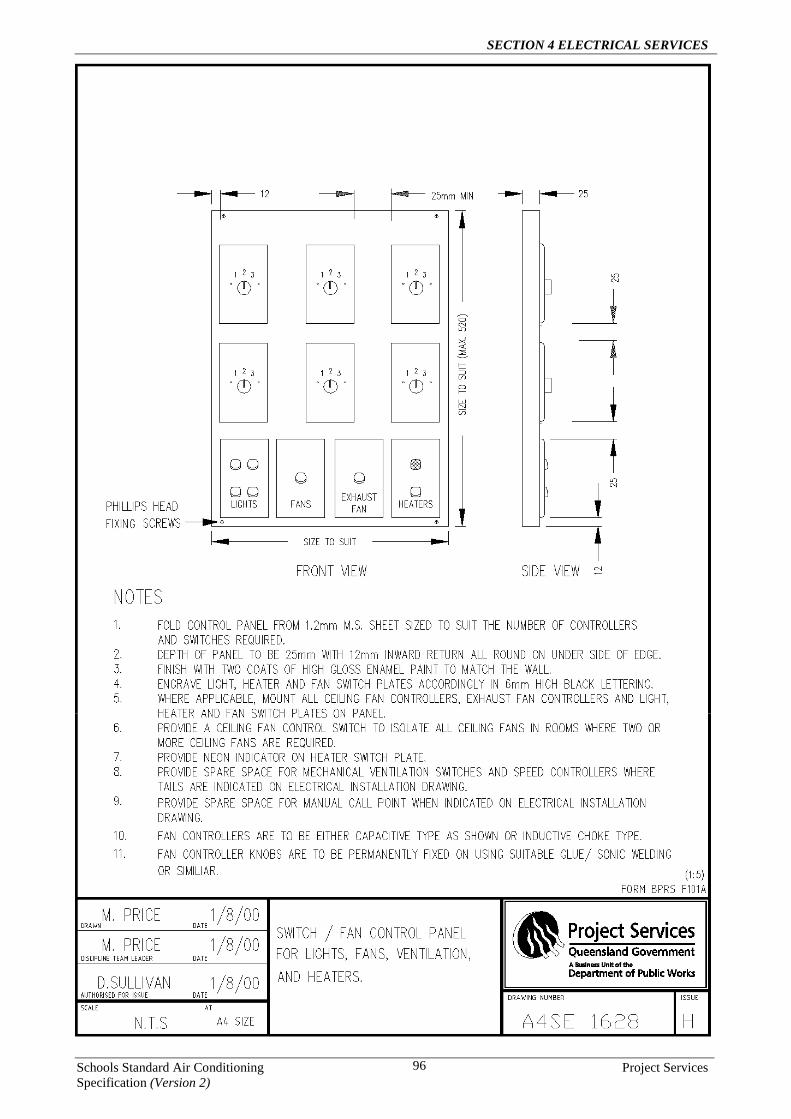
SECTION 4 ELECTRICAL SERVICES
Schools Standard Air Conditioning Project Services Specification (Version 2)
96

SECTION 4 ELECTRICAL SERVICES
Schools Standard Air Conditioning Project Services Specification (Version 2)
97

SECTION 4 ELECTRICAL SERVICES
Schools Standard Air Conditioning Project Services Specification (Version 2)
98

SECTION 4 ELECTRICAL SERVICES
Schools Standard Air Conditioning Project Services Specification (Version 2)
99

SECTION 4 ELECTRICAL SERVICES
Schools Standard Air Conditioning Project Services Specification (Version 2)
100

SECTION 5 DEMOLITION
Schools Standard Air Conditioning Project Services Specification (Version 2)
101
SECTION 5 DEMOLITION
1 GENERAL
1.1 SCOPE OF THIS SECTION This Section sets out the minimum requirements for the removal of existing Evaporative Cooling and Air Conditioning systems where new air conditioning equipment is to be installed. The areas to be air conditioned are nominated in the briefing document.
1.2 CROSS REFERENCES General General: Conform to the General Requirements of the following sections of this Specification; Mechanical: Refer to Section 3 Mechanical Services; Electrical: Refer to Section 4 Electrical Services; Hazardous Materials: Refer to Section 1 – Preliminaries in regards to Asbestos.
1.3 STANDARD General Demolition: To AS 2601. Refrigeration systems General: Undertake demolition work on refrigeration systems in conformance with: - AS/NZS 1677.2.
- The recommendations of SAA HB 40.1 and SAA HB 40.2.
- To limit emission of ozone depleting substances it is important that a refrigeration mechanic, not just the general demolisher, be involved in the demolition and salvage of refrigeration systems. AS/NZS 1677.2, SAA HB 40 contains requirements to control the release of refrigerants during demolition and removal of plant.
1.4 INTERPRETATION Definitions For the purposes of this worksection, the following definitions apply: - Demolition: The complete or partial dismantling of a building or structure, by pre-planned and controlled
methods or procedures.
- Recover: The disconnection and removal of an item in a manner to allow re-installation.
1.5 INSPECTION Notice Inspection: Give notice so that inspection may be made of the following: - Adjacent structures before commencement of demolition.
- Services before disconnection or diversion.
- Trees as documented to be retained, before commencement of demolition.
- Contents of building before commencement of demolition.
- Structure after stripping and removal of roof coverings and external cladding.
- Underground structures after demolition above them.
- Excavations remaining after removal of underground work.
- Site after removal of demolished materials.
- Services after reconnection or diversion.

SECTION 5 DEMOLITION
Schools Standard Air Conditioning Project Services Specification (Version 2)
102
1.6 SUBMISSIONS Authorities Evidence of compliance: Before commencing demolition, submit evidence of the following:
- Requirements of authorities relating to the work under the contract have been ascertained.
- A permit to demolish has been obtained from the appropriate authority (if required)
- A scaffold permit has been obtained from the appropriate authority (if scaffolding is proposed to be used).
- Precautions necessary for protection of persons and property have been taken and suitable protective and safety devices have been provided to the approval of the relevant authority, and the school.
- Treatment for rodent infestation has been carried out and a certificate has been obtained from the appropriate authority.
- Fees and other costs have been paid.
Work plan The Contractor shall not decommission or remove any existing mechanical or electrical services prior to being given access to that part of the work by the Principal, for example, the Contractor can’t remove the existing evaporative cooling system from Block A whilst the building is still occupied. Submit a work plan before demolition or stripping work. Include the following information:
- The method of protection, and support for adjacent property (if required)
- Locations and details of necessary service deviations and terminations.
- If removal of asbestos or of material containing asbestos is required, the contractor will review the Asbestos Register to identify the extent the asbestos and request a Work Area Access Permit (WAAP) from the Principal and provide Work Method Statements for the asbestos related works, in accordance with Section 1 – Preliminaries (Asbestos). The Principal shall issue the Work Area Access Permit (WAAP) to the contractor and close out the WAAP upon satisfactory completion of the works.
Records Dilapidation record: Submit a copy of the dilapidation record for inspection, and obtain a written agreement to the contents of the record, prior to commencement of demolition. Stockpiles Location: Submit the locations for on-site stockpiles to be used for demolished equipment and materials. Coordinate with the locations of storage for other waste streams and prevent mixing or pollution.
2 REMOVAL OF EXISTING MECHANICAL & ELECTRICAL SERVICES
2.1 GENERAL The objective of the removal of the existing mechanical & electrical services is to return the buildings to their original state where possible once the systems have been removed. The standard of making good is to match the original building structure.
Existing Evaporative Cooling & Air Conditioning Units Remove all redundant evaporative cooling & air conditioning units including fixings and supports. The salvaged evaporative units shall be removed from site and disposed of by the Contractor. The salvaged air conditioning units shall be cleaned and handed over to the Head of Facility. The Contractor shall be responsible for keeping a record of all air conditioning units that are returned to the Head of Facility. Existing Bar Heaters Where there are existing bar heaters to be removed, the contractor is responsible for the disconnection, removal and disposal of all electrical cabling to the outlet. All bar heaters are to be left on site with the school and the building is to be made good following the removal of the bar heaters.

SECTION 5 DEMOLITION
Schools Standard Air Conditioning Project Services Specification (Version 2)
103
Electrical Wiring Controls All redundant electrical wiring and controls shall be removed including Mechanical Services Switchboards, fixings and wiring supports. Hydraulic Services All redundant hydraulic services shall be removed as far as practical and capped off to the satisfaction of the Principal. Existing Concrete slabs All concrete slabs shall be removed where existing evaporative cooling and air conditioning units have been removed. General: Using a diamond saw, neatly cut back or trim to new alignment with a clean true face existing concrete slabs to be partially demolished or penetrated. All concrete waste shall be removed and disposed of by the Contractor. Existing Enclosures All evaporative cooling & air conditioning unit’s enclosures shall be removed where existing evaporative cooling and air conditioning units have been removed. The Contractor shall dispose of all waste materials. Existing Evaporative Cooling Ducting All “EXPOSED” evaporative cooling ductwork, supports and fixings shall be removed and disposed of by the Contractor. Ductwork that is concealed within a ceiling space or by a permanent Bulkhead shall remain. Ductwork that remains shall be capped off to adequately ensure that the redundant ducting is verminproof. Existing Air Relief Grilles All existing air relief grilles shall be removed. The Contractor shall make good to match the original building construction, for example, if the grille was installed in a Louver Gallery then a new Louver Gallery shall be installed to replace the removed Grille. Electrical Reticulation Services All redundant switchboards and cables including mains and submain cables shall be removed. The salvaged cables and switchboards shall be removed from site and disposed of by the Contractor. Coordination with the electricity supply authority for the temporary isolation of the supply to the consumer mains. Making Good The Contractor is responsible for all works necessary to make good buildings and site following the removal of the above items to the satisfaction of the Principal. The works shall include but not be limited to the following:
- Rebuilding of windows, brick, block, timber, and sheeted walls, ceilings, and disturbed roof areas.
- Patching and Painting.

SECTION 5 DEMOLITION
Schools Standard Air Conditioning Project Services Specification (Version 2)
104
The following photographs have been included for details of acceptable finishes:
Penetration repair after duct removal (prior to painting)
Before duct removal After duct removal (prior to painting)
Block wall repair after removal of duct
(prior to painting)
Before duct removal After duct removal
After removal of under ceiling duct (prior to painting)
Block wall repair after removal of duct (prior to painting)

SECTION 5 DEMOLITION
Schools Standard Air Conditioning Project Services Specification (Version 2)
105
Before exposed duct removal
After exposed duct removal
Before concealed duct grilles capped off (concealed duct in bulkhead)
Before concealed duct grilles capped off (concealed duct in ceiling)
After concealed duct grilles capped off (concealed duct in ceiling)
After concealed duct grilles capped off (concealed duct in bulkhead)

SECTION 5 DEMOLITION
Schools Standard Air Conditioning Project Services Specification (Version 2)
106
2.2 SUPPORT
Temporary support General: If temporary support is required, certification for its design and installation is required from a professional engineer engaged by the contractor. Existing buildings: Until permanent support is provided, provide temporary support for sections of existing buildings which are to be altered and which normally rely for support on work to be demolished. Ground support: Support excavations for demolition of underground structures. Adjacent structures: Provide supports to adjacent structures where necessary, sufficient to prevent damage resulting from the works.
- Lateral supports: Provide lateral support equal to that given by the structure to be demolished.
- Vertical supports: Provide vertical support equal to that given by the structure to be demolished.
Permanent supports General: If permanent supports for adjacent structures are necessary and are not documented, give notice and obtain instructions.
2.3 PROTECTION Encroachment General: Prevent the encroachment of demolished materials onto adjoining property, outside the safety barrier. Weather protection General: If walls or roofs are opened for alterations and additions or the surfaces of adjoining buildings are exposed, provide temporary covers to prevent water penetration. Provide covers to protect existing plant, equipment and materials intended for re-use. Dust protection General: Provide dust-proof screens, bulkheads and covers to protect existing finishes and the immediate environment from dust and debris. Security General: If a wall or roof is opened for alterations and additions, provide security against unauthorised entry to the building. Temporary screens General: Fill the whole of designated temporary openings or other spaces using dust and weatherproof temporary screens, fixed securely to the existing structure, and install to ensure appropriate shedding of water to avoid damage to retained existing elements or adjacent structures and contents. If a particular sequence is required and is not shown on the drawings, specify it here. This could apply to structural alterations or work to be completed in stages, and should be incorporated in the work plan prepared by the contractor.

SECTION 6 OPERATION AND MAINTENANCE MANUALS
Schools Standard Air Conditioning Project Services Specification (Version 2)
107
SECTION 6 OPERATION AND MAINTENANCE MANUALS
1.1 GENERAL This section outlines the minimum requirements for Operation and Maintenance Manuals.
1.2 AS INSTALLED DRAWINGS All workshop and/or detail drawings shall be modified at completion of the installation and used as ‘as installed’ drawings for inclusion in operation and maintenance manuals. Final copies of the CAD and Adobe Acrobat ‘as installed’ drawings shall be forwarded to the Principal on CD.
1.3 OPERATION AND MAINTENANCE MANUALS Prior to practical completion, prepare and submit for approval, one draft copy of the operation and maintenance manual. The manual shall include ‘as installed’ shop drawings and diagrams together with concise operating and maintenance instructions, schedules and commissioning records specified below. The approval of any such manuals shall not relieve the contractor of any responsibility for the design and operation of the installation. The approval is solely for the purpose of ensuring that the manual includes all necessary data and is ‘fit for purpose’. Within two week’s prior to Practical Completion, three bound sets of the final manual shall be submitted to the Principal. These manuals shall include all revisions requested by the Principal when reviewing the draft manual. The manual shall give a clear, comprehensive description of all the equipment, components and sub-components, principle of operation, method of operation and maintenance procedures. The descriptions shall be accompanied by flow diagrams, line diagrams and any other illustrations necessary to achieve the required objective. Operation and maintenance manuals and associated drawings shall be supplied as a quality publication and shall be as follow: Designer to select type of binding and be consistent with electrical and fire services. • White A4 sized hard cover, Marbig Catologue No. 150694 2D ring vinyl covered binder with main title in
’30 Times Roman’ secondary lettering in 12 and 10 Uni’ upper and lower case as appropriate.
• Titles for the manuals shall be:
OPERATING AND MAINTENANCE MANUAL MECHANICAL SERVICES ‘………………………… STATE SCHOOL’ Spine: ‘………………………… STATE SCHOOL – AIR CONDITIONING’
All material contained in the manual shall be printed by an approved process on approved quality paper. This requirement includes all illustrative material. Include the following type and range of data and information in the manual:
1. Contents Page - List all subsections
2. General description of the project - Air conditioning scope of works (list the area's that were air conditioned)
3. Operating Instructions - operating instructions – include all details necessary for correct start up procedure and sequence of operation of equipment installed.
4. Provision of manufactures installation & operation manuals/information - Provide for air conditioning units, evaporative cooling systems, mechanical ventilation systems & outdoor air fans.
5. Service & Maintenance Procedures and schedules – Provide service & maintenance procedures and schedules as specified in Section 3 – Mechanical Services of this Specification (level 1, 2 & additional services).
SECTION 6 OPERATION AND MAINTENANCE MANUALS
Schools Standard Air Conditioning Project Services Specification (Version 2)
108
6. Service Sheets - Provide a copy of the service sheets to be used during the defects liability period, service sheets must cover all service and maintenance tasks as detailed in Section 3 – Mechanical Services of this Specification.
7. Data collection forms - Provide completed data collection forms for each air conditioning unit, evaporative cooling unit or mechanical ventilation unit installed, use the applicable form provided by the Principal. A separate form must be completed for each air conditioning unit with all applicable fields completed (note that the building plant number is where you put the identification label number installed on the air conditioning unit i.e. AC.B4-1 etc).
8. Outdoor air fan test certificate - Provide a certificate for the outdoor air fans used. The certificate must show the airflows produced at each of the fan unit's set speed increments. The fan testing must be carried out by a recognised authority certified to carry out such tests in accordance with test standard BSB848 Part 1 - 1980 and incorporated in ISO5801
9. Commissioning Data - Provide commissioning data in accordance with Section 3 – Mechanical Services of this Specification.
10. RPEQ Design Certification - Certify the complete air conditioning and supply air system installation for compliance with the Building Act, and for compliance with the design requirements of Section 3 – Mechanical Services of this Specification for each school. Provide the certification on a standard “Form 15” (Mechanical Design Certificate) by an engineer registered as a professional engineer in Queensland (RPEQ). Note: For information with regards to submission of drawings for Building Act Compliance, refer to Section 1 – Preliminaries of this Specification.
11. Drawing List - a complete list of drawing titles and numbers showing final revision number
12. BAC approved drawings - Provide "As Installed" air conditioning installation drawings stamped for compliance with the building act
13. Control system wiring diagrams - Provide schematic drawings for each air conditioning, evaporative cooling unit, package unit, and outdoor air fan system. The drawings must clearly show the operation of the control systems and include all additional controls provided by the contractor and their relation to the air conditioning units "as supplied" controls.
14. Technical data and product data for control system - Provide manufacturers literature for all contractor supplied control system components i.e. timers relays etc.
15. Pest Control Certificate – Provide certification from a licensed Pest Controller that the termite barriers have been re-instated were they have been effected by the works carried out under the Contract.
16. Structural Supports RPEQ Design Certification – Provide certification of all condensing units, evaporative cooling units and fan coil support frames and brackets by an engineer registered as a professional engineer in Queensland (RPEQ). Provide the certification on a standard “Form 15” (Structural Design Certificate).
17. Building Works Certification – Provide a “Form 16” to certify all building works in association with the mechanical services and electrical services works.
18. Electrical Services RPEQ Design Certification - Certify the complete electrical services upgrade installation for compliance with the design requirements of Section 4 – Electrical Services of this Specification for each school. Provide the certification on a standard “Form 15” (Electrical Design Certificate) by an engineer registered as a professional engineer in Queensland (RPEQ).
19. Electrical Certification for air conditioning system wiring - Provide an electrical certificate of test for the complete air conditioning electrical installation, covering the supply wiring to the air conditioning units, interconnecting wiring between indoor & outdoor units, outdoor air fan wiring, and control system wiring. The certificate must certify the following: *that the electrical installation, to the extent that it is affected by the work, has been tested to ensure it is electrically safe and is in accordance with the requirements of the wiring rules, contract documentation, and any other standard applying to the electrical installation under the Electrical Safety Act & Regulations 2002. The certificate of test must include the following information: details of the person who performed the work, the electrical equipment tested, the date that the equipment was tested, and the contractors licence number.

SECTION 6 OPERATION AND MAINTENANCE MANUALS
Schools Standard Air Conditioning Project Services Specification (Version 2)
109
20. Electrical Certification for the electrical upgrade - Provide an electrical certificate of test for the electrical upgrade works. The certificate must certify the following: *that the electrical installation, to the extent that it is affected by the work, has been tested to ensure it is electrically safe and is in accordance with the requirements of the wiring rules, contract documentation, and any other standard applying to the electrical installation under the Electrical Safety Act & Regulations 2002. The certificate of test must include the following information: details of the person who performed the work, the electrical equipment tested, the date that the equipment was tested, and the contractors licence number.
21. Fault level calculations - Provide calculations for all new and existing switchboards, verifying that all new and existing switchboards can withstand the increased fault current of the upgraded supply. Where the calculated fault levels exceeded the switchboard & switchgear ratings, provide details of the solution used to overcome the fault level problem. i.e. FCL fuses installed.
22. Voltage drop & current carrying capacity calculations - Provide calculations to evidence that all new submain cables installed have a current carrying capacity not less than the currents stated in the schedule of submains, and that all new submains have voltage drop that does not exceed the maximum values stated in the schedule of submains.
23. Technical data and product data - For all MSB's, MDSB's & DSB's including switchgear and chassis info, etc.
24. As constructed drawings - Site Plan: Show the location of all new and existing electrical & communications conduits, cable pits, and switchboards. Provide details of all new and existing conduits on the drawing, either in a table format on the drawing or as notes on the drawing (this information can be obtained from the conduit schedule provided and must be verified on site).
25. As constructed drawings - Switchboard layouts and shop drawings: Provide drawings for all new MSB's and MDSB's, Ensure that the MSB & MDSB drawings include type test certification details.
26. As constructed drawings - Single line diagram of distribution system: Provide a single line diagram of the complete distribution system including the following: supply arrangements (transformer details), main switch & metering details, details of all mains & submains including cable size and protection details, and the reticulation system arrangement showing how all switchboard's are supplied. Provide a table on the single line diagram drawing showing all new and existing switchboard information including the following: designation, phases, main switch rating, pole capacity, spare poles, busbar rating, busbar fault rating, and circuit breaker fault rating. Show FCL fuses on drawings where installed.
27. RCD Certification – Provide RCD certification in accordance with Section 4 Electrical Services Clause 3.24
28. Mech & Elec drawings on CD - Provide a CD ROM containing all Mechanical and Electrical drawings in AutoCAD file format once drawings have been assessed and approved. Provide a copy of the manual in PDF file format on the CD.

SECTION 6 OPERATION AND MAINTENANCE MANUALS
Schools Standard Air Conditioning Project Services Specification (Version 2)
110
THIS PAGE INTENTIONALY LEFT BLANK