Embed Size (px)
Citation preview

Illuminating. Always.
Standard 389 SwitchKorry 389 LED illuminated 5/8-inch switch
Korry has engineered its 389 LED switch for
human machine interface (HMI) applications where
superior lighting performance, product reliability,
and system versatility are required.
Surface mounted electronics with the latest
generation of high-brightness LEDs deliver
exceptional illumination characteristics such as
brightness output and dimming control.
The 389’s versatile circuit card assembly (CCA)
design allows for any type of dimming requirement
to be met.
Mechanically interchangeable with most 5/8-inch
switch products, the Korry 389 provides
uncompromising performance in system interface
capabilities.

Korry 389 Assembly and Installation
SpacerSets cap height above panel (optional)
Switch
Mounting sleeve
Connector module
Cam(2x) Mounting screw (2x)Locks mounting sleeve against panel
Single-Sleeve Mounting Configuration
Double-Sleeve Mounting Configuration
SpacerSets cap height above panel (optional)
Switch
Outer sleeve
Connector module
Cam(2x) Mounting screw (2x)Locks mounting sleeve against panel
Inner sleeve
Mounting panel
Universal-Sleeve Mounting Configuration
SpacerSets cap height above panel (optional)
Switch
Connector module
Cam(2x) Mounting screw (2x)Locks mounting sleeve against panel
Mounting sleeve
Switch Circuit Diagram

EnvironmentalTest Specification
Contact resistance MIL-STD-202F, Method 307
Contact bounce MIL-PRF-22885F, Para. 4.7.5
Touch temperature MIL-PRF-22885/109A
Permanency of marking MIL-STD-202F, Method 215J
Strength of actuation means MIL-PRF-22885F Para. 4.7.10
Thermal shock MIL-STD-202F, Method 107G, Condition A
Vibration MIL-STD-810C, Method 514.2, Category B2, Procedure 1A
Shock MIL-STD-202F, Method 213B, Condition B
Moisture resistance MIL-STD-202F, Method 106F
Insulation resistance MIL-STD-202F, Method 302, Condition B
Dielectric withstanding voltage MIL-STD-202F, Method 301MIL-STD-202F, Method 105C, Condition B
Salt spray* MIL-STD-202F, Method 101D, Condition A
Explosion MIL-STD-202F, Method 109B
Sand and dust* MIL-STD-202F, Method 110A
Overload cycling MIL-PRF-22885F, Para.4.7.27
Electrical endurance MIL-PRF-22885F, Para. 4.7.28
Mechanical endurance MIL-PRF-22885F, Para. 4.7.29
Power RTCA/DO-160D, Sections 16 and 17
Audio frequency conducted susceptibility RTCA/DO-160D, Section 18, Category Z
Magnetic effect RTCA/DO-160D, Section 15, Category Z
Induced signal susceptibility RTCA/DO-160D, Section 19, Category Z
Radio frequency susceptibility RTCA/DO-160D, Section 20, Category T
Radio frequency emission RTCA/DO-160D, Section 21, Category M
Lightning induced transient RTCA/DO-160D, Section 22, Category XXC3
Temperature / altitude MIL-STD-810C, Method 504.1, Category 1
Filed of view MIL-PRF-22885F, Para. 4.7.39
Stray light MIL-PRF-22885F, Para. 4.7.38
* Results are based on switches being inside of an enclosure. To meet higher requirements, see further information on sealing options. An enclosure would still be required
6-Pin Connector Module 5-Pin Connector Module Printed Circuit Board (PCB) Headers
19854-XXX module uses M39029/57-354 crimp pins, accepts AWG 22, 24 and 26
28196-XXX module uses M39029/22-192 crimp pins, accepts AWG 20, 22 and 24
38803-0015-pin header
33463-0016-pin header
389 Connector and Header Options
6-Pin Connector Module
44387-001 module uses M39029/57-354 crimp pins. accepts AWG 22,24, and 26. (Only for use with Universal Sleeve Mounting)
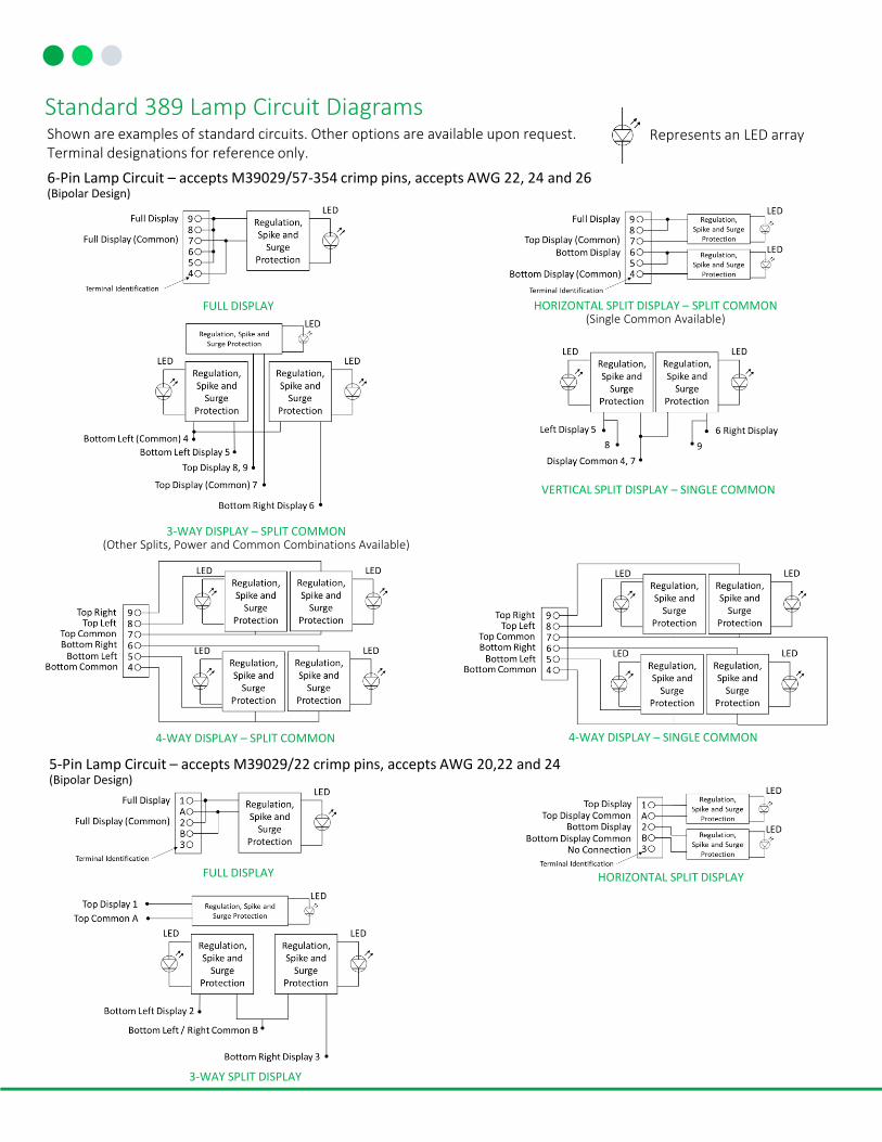
Standard 389 Lamp Circuit DiagramsShown are examples of standard circuits. Other options are available upon request. Terminal designations for reference only.
6-Pin Lamp Circuit – accepts M39029/57-354 crimp pins, accepts AWG 22, 24 and 26 (Bipolar Design)
FULL DISPLAY HORIZONTAL SPLIT DISPLAY – SPLIT COMMON(Single Common Available)
3-WAY DISPLAY – SPLIT COMMON(Other Splits, Power and Common Combinations Available)
VERTICAL SPLIT DISPLAY – SINGLE COMMON
4-WAY DISPLAY – SPLIT COMMON
FULL DISPLAY
3-WAY SPLIT DISPLAY
5-Pin Lamp Circuit – accepts M39029/22 crimp pins, accepts AWG 20,22 and 24 (Bipolar Design)
4-WAY DISPLAY – SINGLE COMMON
HORIZONTAL SPLIT DISPLAY
Represents an LED array

Standard 389 Configuration Envelopes and Panel Cutouts
Single Sleeve and Connector Module
(dimensions in inches)
Single Sleeve and PC Header
Universal Sleeve and Connector Module
Single Sleeve, Connector Module and Bellows Seal
Double Sleeve and Connector Module Panel Cutout for Double Sleeve
Panel Cutout for Single Sleeve
ReliabilityThe Korry 389 switch has an MTBF of 1.5 million hours, which varies by configuration and application. The 1.5-million-hour MTBF is for a standard full display, assuming a 20-degree Celsius ambient operating temperature and 3,000 flying hours per year. This prediction was performed using 217 Plus from RiAC™ software.

Legend TypesNon-Energized
ConditionEnergized Condition
S (1B)Hidden legend. Letters not visible until illuminated. Lighted colored letters on opaque black background when energized
B (1C)Hidden legend. Letters not visible until illuminated. Lighted colored background with opaque black letters when energized
W (2D)Opaque black letters on white background. Background shows color when energized
N (2G2)White letters on opaque black background. Letters show color when energized
C (2B)Opaque black letters on colored background. Lighted colored background when energized
(2F)Opaque white letters on dark background. Background shows color when energized
Legends
KORRY
KORRY
KORRY
KORRY
KORRY
KORRY
KORRY
KORRY
KORRY KORRY
A
Lens Configurations
A B
A A
A
B B
B
C
C
Full Vertical split
Horizontal split 3-way bottom split
3-way top split
BA
C3-way
right split
BC
BA
D4-way split
A
3-way left split
C
Fonts
Commonly Used Fonts
Character heights between 0.090” - 0.125”
FUTURA MEDIUM FUTURA MEDIUM CONDENSEDHELVETICA
MEDIUM
HELVETICA MEDIUM
CONDENSEDGORTON NORMAL GORTON CONDENSED
GORTON EXTRA CONDENSED NEWS GOTHICDIN MITTELSCHRIFT
1451
DIN ENGSCHRIFT 1451
Legends are available in many fonts and character heights. Please contact us for details about your specific request

Variable Voltage
Dimming Methodologies
Optical Characteristics
Pulse Width Modulation (PWM)
Luminance Chromaticity Contrast
Dim @ 14 VDC Bright @ 28 VDC X Y On Off
RED 10 ± 5 200 - 500
0.670 0.334
0.6 Min 0 ± 0.10.670 0.3100.695 0.2850.710 0.292
AMBER 10 ± 5 200 – 500
0.570 0.430
0.6 Min 0 ± 0.10.560 0.4200.600 0.3800.610 0.390
GREEN 10 ± 5 200 – 500
0.200 0.640
0.6 Min 0 ± 0.10.200 0.7400.320 0.7400.320 0.640
BLUE 10 ± 5 150 – 400
0.140 0.250
0.4 Min 0 ± 0.10.140 0.1500.200 0.1500.200 0.250
WHITE 10 ± 5 200 - 500
0.280 0.270
0.6 Min 0 ± 0.10.280 0.3700.340 0.3700.340 0.270
▪ Luminance and color requirements are for legend types S (1B), B (1C), W (2D), C (2B), and (2F)
▪ Type N legends are used for night visibility and are designed to match the light-plate luminance value
▪ NVIS colors are available per MIL-STD-3009
▪ Korry products meet the night-vision compatibility requirements of MIL-STD-3009
▪ Contrast shown is for S legends only
▪ Other optical characteristics are available upon request
Constant Illumination over Variable Voltage
ProgrammableLogic Input
2-to-4-point dimming using multiple ground pins
Property Characteristics
Switch typeMomentary / alternate action, four pole, double throw, form C, single break microswitch IAW MIL-PRF-8805
Switch contact ratingsResistive: sea level 7A at 28 VDCInductive: sea level at 4A at 28 VDCLamp: sea level 2.5A at 28VDC
LED current rating 35mA max at 28 VDC, bright mode, full display
Total cap travel 0.177 inch max. (4.19 mm)
Actuation force 2-5 pounds (0.91-2.27 kg)
Cap extraction 2-5 pounds (0.91-2.27 kg)
Mounting torque 16-20 inch-ounces
Actuation life 100,000 cycles (MIL-PRF-22885)
Temperature -55° C to +85° C (MIL-PRF-22885)
Electrical and Operating Characteristics
Korry Electronics11910 Beverly Park Rd.Everett, WA 98204
Illuminating. Always.
For more information contact us at:+1 425-297-9700 or [email protected]
www.korry.com
APPROVED FOR PUBLIC RELEASE | DISTRIBUTION UNLIMITEDThe information and data given are typical for the equipment described. However, any individual item is subject to change without any notice
Drip proof Sand and dust Waterproof Humidity Spill proof Salt fog
Wiper seal * X X
Internal seal * X X X
External seal * X X X X X X
Bellows seal * X X X X X X
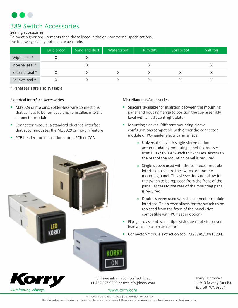
389 Switch AccessoriesSealing accessoriesTo meet higher requirements than those listed in the environmental specifications, the following sealing options are available.
* Panel seals are also available
Electrical Interface Accessories
▪ M39029 crimp pins: solder-less wire connections that can easily be removed and reinstalled into the connector module
▪ Connector module: a standard electrical interface that accommodates the M39029 crimp-pin feature
▪ PCB header: for installation onto a PCB or CCA
Miscellaneous Accessories
▪ Spacers: available for insertion between the mounting panel and housing flange to position the cap assembly level with an adjacent light plate
▪ Mounting sleeves: Different mounting-sleeve configurations compatible with either the connector module or PC-header electrical interface
o Universal sleeve: A single-sleeve option accommodating mounting panel thicknesses from 0.032 to 0.432-inch thicknesses. Access to the rear of the mounting panel is required
o Single sleeve: used with the connector module interface to secure the switch around the mounting panel. This sleeve does not allow for the switch to be replaced from the front of the panel. Access to the rear of the mounting panel is required
o Double sleeve: used with the connector module interface. This sleeve allows for the switch to be replaced from the front of the panel (Not compatible with PC header option)
▪ Flip-guard assembly: multiple styles available to prevent inadvertent switch actuation
▪ Connector-module extraction tool: M22885/108T8234.