Embed Size (px)
Citation preview
LARGE-CAP 389 SWITCH - 1380
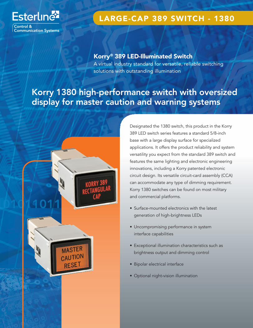
Korry® 389 LED-Illuminated SwitchA virtual industry standard for versatile, reliable switching solutions with outstanding illumination
Korry 1380 high-performance switch with oversized display for master caution and warning systems
Designated the 1380 switch, this product in the Korry
389 LED switch series features a standard 5/8-inch
base with a large display surface for specialized
applications. It offers the product reliability and system
versatility you expect from the standard 389 switch and
features the same lighting and electronic engineering
innovations, including a Korry patented electronic
circuit design. Its versatile circuit-card assembly (CCA)
can accommodate any type of dimming requirement.
Korry 1380 switches can be found on most military
and commercial platforms.
• Surface-mounted electronics with the latest
generation of high-brightness LEDs
• Uncompromising performance in system
interface capabilities
• Exceptional illumination characteristics such as
brightness output and dimming control
• Bipolar electrical interface
• Optional night-vision illumination
1
Switch type Momentary/alternate action, four pole, double throw, form C, single break microswitch IAW MIL-PRF-8805
Switch contact ratings Resistive: sea level 7 A at 28 VDC Inductive: sea level 4 A at 28 VDC Lamp: sea level 2.5 A at 28 VDC
LED current rating 35 mA max. at 28 VDC, bright mode, full display
Total cap travel 0.183 inch max. (4.65 mm)
Actuation force 2-5 pounds (0.91-2.27 kg)
Cap extraction 2-5 pounds (0.91-2.27 kg)
Mounting torque 16-20 inch-ounces
Actuation life 100,000 cycles (MIL-PRF-22885)
Temperature -55° C to +85° C (MIL-PRF-22885)
Electrical and Operating Characteristics
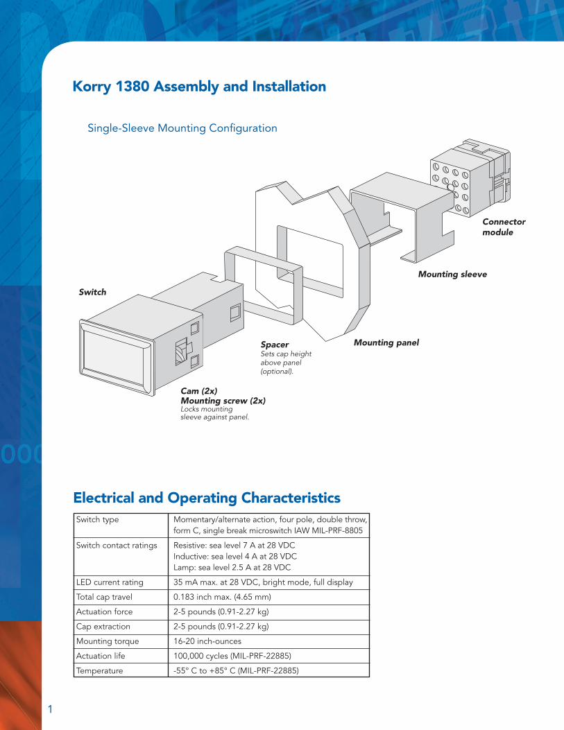
Korry 1380 Assembly and Installation
Single-Sleeve Mounting Configuration
Connectormodule
Cam (2x)Mounting screw (2x) Locks mounting sleeve against panel.
Switch
SpacerSets cap height above panel (optional).
Mounting sleeve
Mounting panel
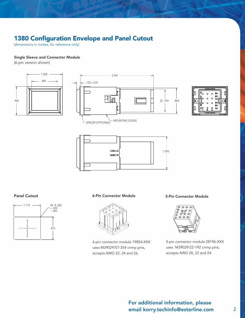
1380 Configuration Envelope and Panel Cutout(dimensions in inches, for reference only)
For additional information, please email [email protected] 2
Panel Cutout 6-Pin Connector Module 5-Pin Connector Module
6-pin connector module 19854-XXX
uses M39029/57-354 crimp pins,
accepts AWG 22, 24 and 26.
5-pin connector module 28196-XXX
uses M39029/22-192 crimp pins,
accepts AWG 20, 22 and 24.
Single Sleeve and Connector Module(6-pin version shown)
1.095
.960
1.200
.885
2.461
.754 .860
.125 ±.015
MOUNTING SLEEVESPACER (OPTIONAL)
1.115
.875
4X R .060 + .005 - .025
1.095

3
1380 Electrical Schematics and Interface OptionsShown are examples of standard circuits. Other options are available upon request. Terminal designations are for reference only.
Lamp Circuit (bipolar design)
Switch Circuit
657
151416
121113
9810
Terminal identification is optional.
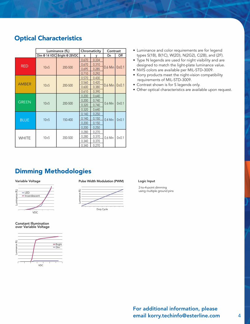
Optical Characteristics
• Luminance and color requirements are for legend types S(1B), B(1C), W(2D), N(2G2), C(2B), and (2F). • Type N legends are used for night visibility and are designed to match the light-plate luminance value.• NVIS colors are available per MIL-STD-3009. • Korry products meet the night-vision compatibility requirements of MIL-STD-3009.• Contrast shown is for S legends only.• Other optical characteristics are available upon request.
For additional information, please email [email protected] 4
Chromaticity x y 0.670 0.334 0.670 0.310 0.695 0.285 0.710 0.292 0.570 0.430 0.560 0.420 0.600 0.380 0.610 0.390 0.200 0.640 0.200 0.740 0.320 0.740 0.320 0.640 0.140 0.250 0.140 0.150 0.200 0.150 0.200 0.250 0.280 0.270 0.280 0.370 0.340 0.370 0.340 0.270
Luminance (fL) Contrast Dim @ 14 VDC Bright @ 28VDC On Off
10±5 200-500 0.6 Min 0 ±0.1
10±5 200-500 0.6 Min 0 ±0.1
10±5 200-500 0.6 Min 0 ±0.1
10±5 150-400 0.4 Min 0 ±0.1
10±5 200-500 0.6 Min 0 ±0.1
RED
AMBER
GREEN
BLUE
WHITE
Pulse Width Modulation (PWM) Variable Voltage
Constant Illumination over Variable Voltage
Dimming Methodologies
2-to-4-point dimming using multiple ground pins
LEDIncandescent
Lum
inan
ce (f
L)
VDC
DimBright
VDC
Lum
inan
ce (f
L)
Duty Cycle
Lum
inan
ce (f
L)
Logic Input

Legends
5
OFF CONDITION
ON CONDITION
S (1B)Hidden legend. Letters not visible until illuminated. Lighted colored letters on opaque black background when energized.
B (1C)Hidden legend. Letters not visible until illuminated. Lighted colored background with opaque black letters when energized.
W (2D)Opaque black letters on white background. Background shows color when energized.
N (2G2)White letters on opaque black background. Letters show color when energized.
C (2B)Opaque black letters on colored background. Lighted colored background when energized.
(2F)Opaque white letters on dark background. Background shows color when energized.
KORRY
KORRY
KORRY
KORRY KORRY
KORRY
KORRYKORRY
KORRYKORRY
Legend Types
Number of characters per line can vary depending on characters selected. Other fonts are available upon request.
TEXTTEXTTEXT
LinesCharacters
per lineCharacter height LinesCharacters
per line
TEXT
.093 1-4 10 1-2 10 .100 1-4 9 1-2 9 .125 1-3 8 1 8 .156 1-3 6 1 6 .093 1-4 16 1-2 16 .100 1-4 15 1-2 15 .125 1-4 11 1-2 11 .156 1-3 9 1 9 .093 1-4 9 1-2 9 .100 1-4 8 1 8 .125 1-4 7 1 7 .156 1-2 6 1 6 .093 1-4 11 1-2 11 .100 1-4 10 1-2 10 .125 1-7 9 1 9 .156 1-3 7 1 7 .093 1-4 10 1-2 10 .100 1-4 9 1-2 9 .125 1-3 7 1 7 .156 1-3 6 1 6 .093 1-4 10 1-2 10 .100 1-4 9 1-2 9 .125 1-3 9 1 9 .156 1-3 7 1-3 7 .093 1-5 16 1-2 16 .100 1-4 12 1-2 12 .125 1-3 12 1 12 .156 1-3 10 1 10 .093 1-5 12 1-2 12 .100 1-4 11 1-2 11 .125 1-4 9 1-2 9 .156 1-3 7 1 7 .093 1-5 10 1.2 10 .100 1-4 9 1-2 9 .125 1-4 8 1-2 8 .156 1-3 6 1 6 .093 1-4 15 1-2 15 .100 1-4 14 1-2 14 .125 1-4 11 1.2 11 .156 1-3 9 1 9
Fonts and Sizes Versus Character Capacities
Futura Medium
Futura Medium
Condensed
Helvetica Medium
Helvetica Medium Condensed
News Gothic
DIN Mittelschrift 1451
DIN Engschrift 1451
Lens Configurations
Full
A
Horizontal split
BA
For additional information, please email [email protected] 6
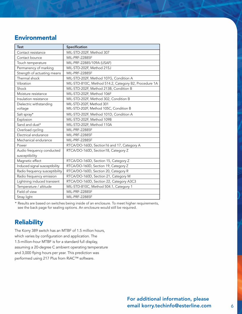
Environmental
The Korry 389 switch has an MTBF of 1.5 million hours, which varies by configuration and application. The 1.5-million-hour MTBF is for a standard full display, assuming a 20-degree C ambient operating temperature and 3,000 flying hours per year. This prediction was performed using 217 Plus from RiAC™ software.
Reliability
Test Specification
Contact resistance MIL-STD-202F, Method 307Contact bounce MIL-PRF-22885FTouch temperature MIL-PRF-22885/109A (USAF)Permanency of marking MIL-STD-202F, Method 215JStrength of actuating means MIL-PRF-22885FThermal shock MIL-STD-202F, Method 107G, Condition AVibration MIL-STD-810C, Method 514.2, Category B2, Procedure 1AShock MIL-STD-202F, Method 213B, Condition BMoisture resistance MIL-STD-202F, Method 106FInsulation resistance MIL-STD-202F, Method 302, Condition BDielectric withstanding MIL-STD-202F, Method 301voltage MIL-STD-202F, Method 105C, Condition B
Salt spray* MIL-STD-202F, Method 101D, Condition AExplosion MIL-STD-202F, Method 109BSand and dust* MIL-STD-202F, Method 110AOverload cycling MIL-PRF-22885FElectrical endurance MIL-PRF-22885FMechanical endurance MIL-PRF-22885FPower RTCA/DO-160D, Section16 and 17, Category AAudio frequency conducted RTCA/DO-160D, Section18, Category Zsusceptibility Magnetic effect RTCA/DO-160D, Section 15, Category ZInduced signal susceptibility RTCA/DO-160D, Section 19, Category ZRadio frequency susceptibility RTCA/DO-160D, Section 20, Category RRadio frequency emission RTCA/DO-160D, Section 21, Category M Lightning induced transient RTCA/DO-160D, Section 22, Category A3C3Temperature / altitude MIL-STD-810C, Method 504.1, Category 1Field of view MIL-PRF-22885FStray light MIL-PRF-22885F
* Results are based on switches being inside of an enclosure. To meet higher requirements, see the back page for sealing options. An enclosure would still be required.
© 2016, Esterline Technology Corporation. “Korry” is a registered trademark of Esterline Technologies Corporation.
SEP16
Control &Communication Systems
Esterline11910 Beverly Park RoadEverett, WA 98204425-297-9700www.esterline.com
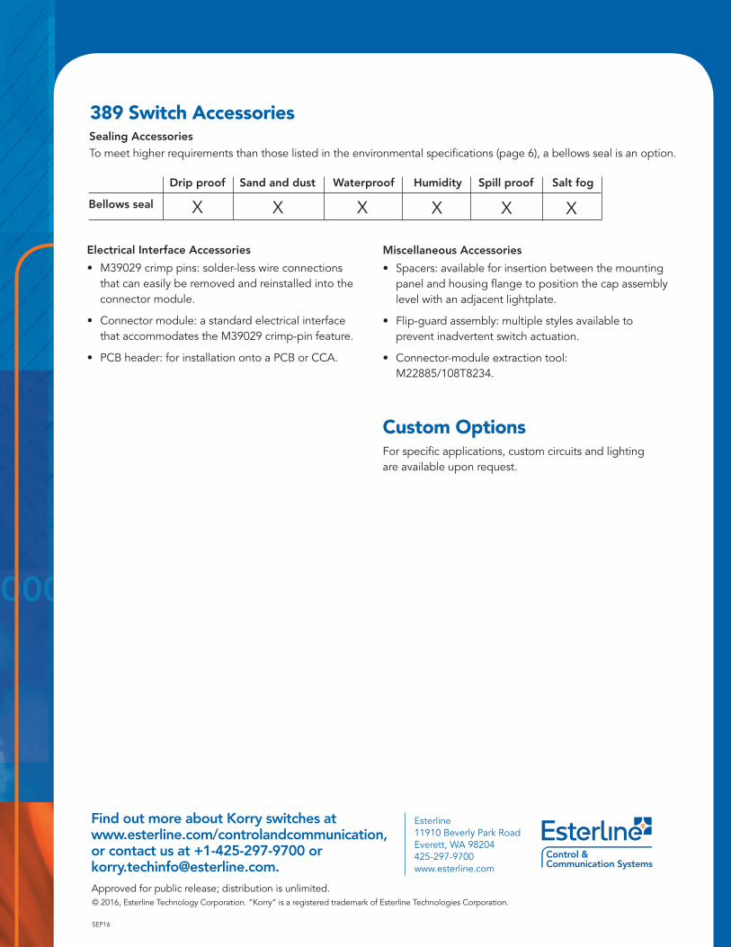
389 Switch AccessoriesSealing Accessories To meet higher requirements than those listed in the environmental specifications (page 6), a bellows seal is an option.
Drip proof Sand and dust Waterproof Humidity Spill proof Salt fog
Bellows seal X X X X X X
Find out more about Korry switches atwww.esterline.com/controlandcommunication,or contact us at +1-425-297-9700 [email protected].
Electrical Interface Accessories
• M39029 crimp pins: solder-less wire connections that can easily be removed and reinstalled into the connector module.
• Connector module: a standard electrical interface that accommodates the M39029 crimp-pin feature.
• PCB header: for installation onto a PCB or CCA.
Miscellaneous Accessories
• Spacers: available for insertion between the mounting panel and housing flange to position the cap assembly level with an adjacent lightplate.
• Flip-guard assembly: multiple styles available to prevent inadvertent switch actuation.
• Connector-module extraction tool: M22885/108T8234.
Custom OptionsFor specific applications, custom circuits and lighting are available upon request.


![Christopher Columbus [1451- 1506] Columbus’ Four Voyages](https://img.pdfslide.us/doc/110x75/56649cec5503460f949b8589/christopher-columbus-1451-1506-columbus-four-voyages.jpg)