Embed Size (px)
Citation preview

Standard 313 Companion Document Index
Companion Document Companion Documents Subject
1..............Technical Material on file with the NRCS State Conservation Engineer
2..............Assessments, Management Assessment, and Site Assessment 313-2A........ Management and Site Assessment Worksheet (for smaller facilities) 313-2B........ Management Assessment Worksheet (for medium size facilities) 313-2C........ Management Assessment Worksheet (for large size facilities) 313-2D........ Site Assessment Worksheet (for medium and large size facilities) 313-2E........ Management and Site Assessment Worksheet (for stacks in field)
3..............Soil Test Pit/Boring Logs 313-3A........ Soil Test Pit/Boring Log 313-3B........ Soil Test Pit/Boring Log 313-3C........ Summary of Soil Profile Information
4..............Waste Storage Facility Design Spreadsheet
5..............Monthly Precipitation and Evaporation in Wisconsin
6..............Monthly Runoff from Animal Lots in Wisconsin
7..............Daily Manure Production for Livestock
8..............Sand Bedding and Sand Laden Manure (SLM) Handling
9..............Separation Distance Measurement to Saturation and Bedrock
10............Geomembrane Liners in Waste Storage Facilities 313-10A...... Geomembrane Liner Inspection Plan
11............Concrete Joints- Construction, Control, Expansion, Isolation
12............Control Joint Spacing for Slabs Using Subgrade Drag Equation
13............Checklist for Waste Storage Facility Plan Review
14............Clay Liners
15............Sumps in Waste Storage Facilities
16............Saturation, How to Handle It
17............Standard Designs for Reinforced Concrete Walls, Guide for Use
18............Joining Impoundment Liners
19............Karst Information These companion documents are narratives, forms, and tools that can help with the application of the 313 standard. They are not criteria, but they can help apply the criteria in the standard. Users can and should develop their own forms to use as needed.
Agricultural Waste Management Field Handbook Notice WI-31, April 2009

COMPANION DOCUMENT 313-1
TECHNICAL MATERIAL ON FILE WITH THE NRCS STATE CONSERVATION ENGINEER Contact Information: John Ramsden, State Conservation Engineer
USDA- Natural Resources Conservation Service 8030 Excelsior Drive, Suite 200 Madison, WI 53717 608-662-4422 Ext. 234
Manure Pit Leakage Research This is a three-ring binder of research reports. Over twenty reports are included. Titles are listed at the end of this companion document.
Clay Liners & Geosynthetic Clay Liners (GCLs) for Manure Storage This is a three-ring binder of material by Dr. David Daniels. It deals with seepage through clay and GCL liners and construction of them. It was presented at a two-day class in 1997 in Minnesota attended by staff from DATCP, NRCS, and some Wisconsin private consultants. Also on file is a three-ring binder from CETCO dealing with technical reference material for GCLs.
Karst This is a three-ring binder of material about Karst topography and features. Included are documents such as the USGS Circular 968, “Development of Sinkholes Resulting from Man’s Activities in the Eastern United States” and maps such as a map of Wisconsin showing areas of carbonate bedrock with less than 50 feet of material overlying it. Also included are maps of bedrock features in Door County and material on Karst features in southeast Minnesota and methods of dealing with manure storage ponds in that area.
Pleistocene Geology Material from Wisconsin Geological and Natural History Survey This includes Pleistocene Geology reports from Dane County, Juneau County, Adams County, Portage County, Sauk County, and Lancaster and Hurricane Quadrangle Maps for Grant County.
“Designing with Geosynthetics”, Fourth Edition This is a book written by Dr. Robert M. Koerner, Professor of Civil Engineering at Drexel
University, and Director of the Geosynthetics Research Institute
Outdated Manure Storage Standards The State Conservation Engineer has a copy of all previously issued manure storage standards.
Agricultural Waste Management Field Handbook Notice WI-25, January 2005

Companion Document 313-1
Agricultural Waste Management Field Handbook Notice WI-25, January 2005
Manure Pit Leakage Research- Reports on file: - NRCS Workshop for Seepage Control in Manure Storage Ponds, 2000
- Compacted Clay Liner Case Studies For Animal Waste Ponds, 2001
- Design and Construction of a Waste Storage Pond Seepage Monitoring System, 1997
- MPCA Guidelines for Design of Cohesive Soil Liners for Manure Storage Structures, 1998
- Technical Guidance for Ground water Monitoring at newe Feedlots in Minnesota, 7/97
- Synopsis of 9 of the best articles on Manure Pit Leakage, R. Wilson, 1/98
- Synopsis of 8 articles on Manure Pit Leakage, Mike Tiry, 8/97
- Evaluation of Soil Under an Earthen Manure Storage Pond, Perschke et al, 1998
- A Laboratory Assessment of Agricultural Waste Storage Soil liner Hydraulic Conductivity Performance Using Construction Quality Control Procedures, Hootkany & Warner, 1997
- Hydraulic Conductivity Behavior of Soil Liners in Agricultural Waste Containment Facilities, Hootkany, 1994
- Designing Earthen Storage Facilities for Manure, Barrington & Broughton, 1988
- The Concentration of Liquid Manure Affects Its Infiltration Into Soil, Detar, 1977
- Soil Sealing by Manure in Various Soil Types, Barrington, 1983
- The Sealing Mechanism of Waste Water Ponds, Chang et al, 1974
- Infiltration Characteristics from Anaerobic Lagoons, Hills, 1976
- Ion Movement immediately beneath earthen hog manure storages; How Much, How deep, and How Fats, Maule & Fonstad, 1996
- Do Waste Treatment Lagoons Leak?, Moffitt et al in SCS, 1993
- Evaluating Seepage Potential from Animal Waste Lagoons, McElroy et al in SCS, 1993
- Swine Lagoon Seepage in Sandy Soil, Westerman et al, 12/93
- Unsaturated Seepage from a Feedlot Runoff Storage Pond, Parker et al, 1995
- Sealing of Surface Impoundments, Branch, EPA, 1989
- Conclusions on Biological Sealing Research, Phillips in SCS, 1979
- Several SCS documents on manure pit sealing from the early 1970’s
- Dairy Waste Ponds Effectively Self Sealing, Davis, 1973
- Effects of Microorganisms on Permeability of Soil under Prolonged Submergence, Allison, 1947

COMPANION DOCUMENT 313-2
ASSESSMENTS, MANAGEMENT ASSESSMENT AND SITE ASSESSMENT All waste storage facilities and manure transfer systems need a management assessment and a site assessment as specified in Standards 313 and 634. If a given job includes both waste storage and manure transfer, one set of assessments is adequate. The assessments may be done in any format, but they must include all information required in the standards. Several optional assessment worksheets are presented here. Use of these forms will meet the requirements for assessments in the standards: 2A Management and Site Assessment Worksheet - This is a combined management and
site assessment worksheet for use with smaller facilities, i.e. traditional stanchion barns, grazing farms, and small free stalls. These assessments would generally fit operations with fewer than 300 cows or heifers.
2B Management Assessment Worksheet - This is a more detailed management
assessment worksheet for medium size facilities. It will generally fit operations having from 100 to 500 cows or heifers.
2C Management Assessment Worksheet - This is a more comprehensive management assessment worksheet for larger facilities. It will generally fit operations having 300 or more cows or heifers.
2D Site Assessment Worksheet - This worksheet is for medium and large facilities. Use this
worksheet with 2B or 2C above. 2E Management and Site Assessment Worksheet - This worksheet is only for stacking
waste outside the animal production area. For stacks of waste within the animal production area use the criteria in Standard 313, Tables 1 through 6 and use the appropriate assessment sheets from above - 2A through 2D.
Agricultural Waste Management Field Handbook Notice WI-25, January 2005
Companion Document 313-2
MANAGEMENT AND SITE ASSESSMENT WORKSHEET (313-2A) Waste Storage Facility (313) and/or Manure Transfer (634)
Farmer/Landowner: _________________________________ Assessment Interviewer: ______________________________ Date: _________________ ~~~~~~~~~~~~~~~~~~~~~~~~~~~~~~~~~~~~~~~~~~~~~~~~~~~~~~~~~~~~~~~~~~~~~~~~
MANAGEMENT ASSESSMENT Intent/purpose
How will the Animals and Waste be managed?
Include these items in narrative: Housing types Lots Storage type planned Transfer to and from Storage
(Also- Sketch the site on separate sheet)
Waste Characterization – Include the first sheet of the Waste Storage Facility design
spreadsheet, and, if it’s a dairy with a parlor, include the wastewater sheet. ~~~~~~~~~~~~~~~~~~~~~~~~~~~~~~~~~~~~~~~~~~~~~~~~~~~~~~~~~~~~~~~~~~~~~~~~
SITE ASSESSMENT A. Site – Describe these items and show on sketch as appropriate Buildings Animal lots
Fences Roads, lanes
Property lines Setbacks
Wells Surface channels
Drain tile
Floodplains Utilities, overhead lines Easements Wetlands B. Soils Investigation – attach “Summary of Soil Profile information – 3C” C. Embankment Construction – D. Liner construction – E. Borrow area –
Agricultural Waste Management Field Handbook Notice WI-25, January 2005

Companion Document 313-2
MANAGEMENT ASSESSMENT WORKSHEET (313-2B) Waste Storage Facility (313) and/or Manure Transfer (634)
Farm: _______________________________ Owner/Operator _________________________ By: _________________________________ Date: __________________ I. Why is waste being stored? (Circle all applicable.) Nutrient Management Ordinance Requirement Notice of Discharge Convenience Animal Lot Runoff Problem Other: II. Waste Characterization
a. Manure – Use this table or include first sheet of Waste Storage Facility Design Spreadsheet
Animal Type (management
groups)
Number Total Head
Average Weight per head
Housing Type
Waste Consistency
liquid (I) dilute (d) solid (s)
Bedding Type
Bedding Volume
Days of Storage
b. Milking Center Wastewater: (Describe or include wastewater sheet from spreadsheet.)
c. Dilute wastewater, volume and type (source): d. Milk production level (RHA-lb./yr.):
III: Land base available for waste utilization a) Cropland acres: Owned ____ acres Rented ____ acres Total _____ acres
b) Spreading intentions (where, when and how)
IV. Waste transfer methods:
Agricultural Waste Management Field Handbook Notice WI-25, January 2005
Companion Document 313-2
V. Storage method(s) (circle all applicable): Concrete Tank Lined Pond Concrete Slab and Walls Other: In-Place Earth Pond VI. Method to empty storage facility: VII. Access needs to transfer system and/or waste storage facility) cleaning,
emptying, ramps, etc.):
VIII. Safety issues (tanks, ramps, fences, ventilation, etc.):
IX. Labor and equipment needs regarding the transfer and removal of manure:
X. Odor, aesthetics, animal health:
XI. Future plans, expansion considerations:
Agricultural Waste Management Field Handbook Notice WI-25, January 2005

Companion Document 313-2
MANAGEMENT ASSESSMENT WORKSHEET (313-2C) Concentrated Animal Feedlot Operations (CAFOs)
Waste Storage Facility (313) and/or Manure Transfer (634) Farm: ________________________ Owner/Operator ____________________________ By: _ Date: __________ Location of Waste Facility: _____ ¼ of _____ ¼, Sec. _____, T. _____, R. _____ Township: ____________________, County __________________ I. Animal Unit Calculation:
Animal Type
Current Number of
Animals/Type Average Weight per Animal/Type
Animal Unit Equilavency
Conversion Factor
Total Animal Units per Animal
Type
*Total Animal Units *If greater than 1,000 Animal Units, A Wisconsin Pollutant Discharge Elimination System (WPDES) Permit is required. II. Land Base Available for Waste Utilization Refer to USDA/NRCS FOTG Standard 590 for waste utilization specifics: a) Cropland acres: Owned acres, Rented acres Total acres b) Intent to winter spread: Yes No ______ c) Acres/Animal Units (Ratio): Owned , Rented , Total _____ III. Intent/purpose Statement of Practice Implementation:
A) Waste Processing and Treatment Strategies: Describe purpose of treatment and its intent relative to solid and nutrient distribution, landspreading rates, odor control and distribution strategies:
B) Processing and Treatment By-products (mat’l description, consistency, volumes, etc.)
Organic Solids: Dilute Liquids: Gas Production:
Agricultural Waste Management Field Handbook Notice WI-25, January 2005

Companion Document 313-2
IV. Waste Characterization and Volume Estimates: a) Manure Production:
Animal Type-
Management
Group
Housing
Type
Waste Consistency
Liquid (1)
Dilute (d)
Solid(5)
Number: Total Head
Average
Weight
per head
LB.
Daily Manure
Production per
head
(Cu. Ft.)
Volume
per
day/group
(Cu. Ft.)
Storage Period _______________ days
Total Volume/Storage Period _____________ Cu. Ft. or _______________ gallons
b) Bedding Utilization and Volume: Bedding Type Volume per Head/Stall
Cu. Ft.
Number of Head/Stalls Volume
(Cu. Ft.)
Storage Period _______________ days
Total Volume/Storage Period __ Cu Ft. or ______________ gallons
c) Dilute Wastewater Utilization and Volume: Dilute Wastewater
Source
Volume per Head
Gallons
Number of Head Volume
Gallons
Storage Period _______________ days
Total Volume/Storage Period __ Cu Ft. or __________________ gallons
Total Volumes/ All Sources ______ ________ Cu. Ft. or _________________ gallons 3/3 Are all Wastes to be stored in single Waste Facility? ______ Yes, _______ No If no, how many containment facilities will be used? ____________
Agricultural Waste Management Field Handbook Notice WI-25, January 2005

Companion Document 313-2
V. Storage method (Facility Type): VI. Liner options and preferences: (Construction Specification Requirements) VII. Waste Transfer methods (Refer to Std 634): VIII. Method to empty storage facility/Special Access Needs: IX. Access needs to transfer system and/or waste storage facility: X. Safety issues:
a) Animal and Human Safety (entry, equipment contact, fencing, gating, etc.):
b) Structural failure Safety (secondary containment, resource protection, discharge impacts, etc.):
XI. Labor and Management Issues: XII. Odor, aesthetics, animal health: XIII. Expansion provisions:
Agricultural Waste Management Field Handbook Notice WI-25, January 2005

Companion Document 313-2
SITE ASSESSMENT WORKSHEET (313-2D) Waste Storage Facility (313) and/or Manure Transfer (634)
Farmer/Landowner: _______________________________ Assessment Interviewer: ___________________________ Date: _____________ ~~~~~~~~~~~~~~~~~~~~~~~~~~~~~~~~~~~~~~~~~~~~~~~~~~~~~~~~~~~~~~~~~~~~~~~~ 1. Sketch the site and add photos and/or maps as needed
2. Consider these items and describe or add to sketch:
- Buildings - locations and elevations
- Roads, lanes
- Property lines, setbacks
- Wells
- Floodplains
- Surface channels
- Drain tile
- Utilities, overhead lines
- Easements
- Cultural resources
- Wetlands
- Other
3. Test pit information: attach “Summary of Soil Profile Information” (3C)
4. Karst features- describe any within 1,000 feet
5. Type(s) of storage facility being considered
6. Liner type
7. Borrow description
8. Failure impacts
Agricultural Waste Management Field Handbook Notice WI-25, January 2005

Companion Document 313-2
Agricultural Waste Management Field Handbook Notice WI-25, January 2005
MANAGEMENT AND SITE ASSESSMENT WORKSHEET (313-2E) For Waste Stacked Outside the Animal production Area
Farmer/Landowner: ___________________________ Location of Manure Stack: ____ ¼ of _____ ¼ of Sec. ______, T. ______, R. _______ Township _______________, County ________________
Assessment Interviewer: _______________________ Date: ___________ ~~~~~~~~~~~~~~~~~~~~~~~~~~~~~~~~~~~~~~~~~~~~~~~~~~~~~~~~~~~~~~~~~~~~~~~
MANAGEMENT ASSESSMENT Stacking Plan (Gen’l. Desc.) Site history - Has the proposed site been previously utilized as a stacking site? ______ Y or N
If yes, describe when and what was stored. Waste Characterization:
Waste Source Housing Type Consistency-
Percent (%)SolidsStacking Period
(Days) Total Volume
(cu. ft.) Volume to be Stacked ________ Cu. Ft.; Stack height _____ ft; Area of stack _____ X _____ ~~~~~~~~~~~~~~~~~~~~~~~~~~~~~~~~~~~~~~~~~~~~~~~~~~~~~~~~~~~~~~~~~~~~~~~~
SITE ASSESSMENT Sketch site and include photos and/or USGS Quad sheets as needed
1) Soil Mapping Unit: ______________; Hydrologic Soils Group: ______
2) Subsurface Separation Distance: - Depth to Bedrock:_______ ft Depth to Saturation: _______ft - Soil Investigation Summary: Show soil borings on sketch and attach “Summary of Soil
Profile Information – 3C”
3) Upslope of Proposed Stack : - Is there a tributary diversion? ____ Y or N; Undiverted Drainage Area _____ acres
4) Downslope of Proposed Stack: - Overland Flow Buffers: _____ Y or N; If Yes, describe:
5) Surface Separation Distances: - Wells ________ ft - Quarries __________ ft - Streams __________ ft - Lakes _______ ft - Sinkholes or other Karst features _________ ft - Property lines, setbacks _________ ft - Wetlands and Surface Inlets ___________ ft - Flood plains __________ ft - Surface Channels, Drain Tiles, and other Concentrated Flows _________ ft - Surface Slopes ___________ % - Utilities, overhead lines ____________ - Easements _____________________ - Cultural resources _______________
COMPANION DOCUMENT 313-3
Soil Test Pit/Boring Logs
Attached are several examples of sheets which can be used to log soil test pit/boring information (sheets 3A and 3B). Either sheet can be used, or the designer can make up a custom form. Sheet 3C or a similar sheet should be used to summarize the soil information. It should also be attached to all site assessments.
Agricultural Waste Management Field Handbook Notice WI-25, January 2005

Companion Document 313-3
SOIL TEST PIT/BORING LOG 313-3A
Contact Diggers Hotline prior to investigation. (1-800-242-8511) Practice to be applied: (a) Waste Storage Facility – 313 Logged by: ________________ (b) Manure Transfer – 634 Date: _______________
Project: _____________________________________________________________________
Legal description: Section _____ Township _____ Range _____ County ________________
Soil type (soil mapping unit)______________________________________________________
Topography/glacial features______________________________________________________
Test pit/boring number: __________________ Elevation of top of test pit/boring ________
Test pit/boring location: _________________________________________________________
Horizon Depths
(ft.)
Soil Classifi-cation USCS Color
Percent Fines
(Estimate)
Bedrock Depth &
Type Saturation/ Moisture
Regional Water Table Depth
Soil Sample Taken Other
0
Remarks/comments: ___________________________________________________________
____________________________________________________________________________
____________________________________________________________________________
Agricultural Waste Management Field Handbook Notice WI-25, January 2005

Companion Document 313-3
SOIL TEST PIT/BORING LOG 313-3B
Contact Diggers Hotline prior to investigation. (1-800-242-8511)
Project: ____________________________
Hole/Boring No.: _____________________
Surface Elevation: ___________________
Logged By: _________________________
County: ___________________________
Practice: ___________________________
Location: __________________________
Date: _____________________________
Depth Ft. USCS Description of Materials Sample no. and depth
Description of materials should include: 1) amounts of clay, silt, sand, gravel, and stone and sizes of the sand, gravel and stone or
composite gradation and sand and gravel size; 2) color; 3) seeps and regional water table; and 4) plasticity of fines. Also note the depth samples were taken.
Agricultural Waste Management Field Handbook Notice WI-25, January 2005

Companion Document 313-3
SUMMARY OF SOIL PROFILE INFORMATION 313-3C Farmer/Operator: ______________________________ Date: _______________ Technician/Designer: ___________________________________________ I. Saturation:
a) Describe type(s) and locations(s) and specify holes where found
b) Limiting elevation of saturation (Regional High Water Table (RWT)): _______________
b) Describe how other saturation should be dealt with (tile, over-excavation, nothing …). Other:
II. Bedrock
Type of bedrock
Capability of excavation
Unconsolidated bedrock elev.
Consolidated bedrock elev.
Moisture condition at bedrock surface
III. Soil Samples
Attach lab report(s) with summary.
Soil Sample #1
Soil Sample #2
Soil Sample #3
Soil Sample #4
Hole/Boring Number Disturbed Sample (D) Undisturbed Sample (U)
Soil Sample Depth (inches)
Plasticity Index (PI)
Mechanical Analysis P-200
Permeability, cm/sec
IV. Show the pit/boring locations and elevations on the site assessment sketch.
Agricultural Waste Management Field Handbook Notice WI-25, January 2005
COMPANION DOCUMENT 313-4
WASTE STORAGE FACILITY DESIGN SPREADSHEET
An Excel spreadsheet for sizing waste storage facilities and for computing quantities called “Waste Storage Design” can be found on the WI NRCS web page:
http://www.wi.nrcs.usda.gov/technical/eng_spreads.html
The spreadsheet will size round or rectangular waste storage facilities. Rectangular storage facilities can have vertical or sloping sides. Quantities are computed for cut and fill.
The spreadsheet includes quantity computations for:
Earthwork Volumes Clay Liner Volumes Concrete Liner Volumes HDPE Liner Areas GCL Liner Areas
It does not include computations for ramps because they are so variable in use.
It also does not figure costs.
The spreadsheet includes a tab for wastewater including the milking parlor, sprayers and misters, drinking water tank cleaning, and floor flushing. Default values are shown or known values can be inserted.
The data needed to use the spreadsheet can be obtained from the other companion documents:
Items Companion Documents(s)
Manure volume ............................................. 313 - 7
Runoff, monthly ............................................. 313 - 6
Precipitation & Evaporation, monthly ............ 313 - 5
Agricultural Waste Management Field Handbook Notice WI-25, January 2005

COMPANION DOCUMENT 313-5
MONTHLY PRECIPITATION AND EVAPORATION IN WISCONSIN 1
Month
Average Precipitation
(Inches)
2 Average Evaporation Open Water
(Inches)
Net Precipitation less Evaporation
Open Water Condition (Inches)
January 1.1 0.3 0.8 February 0.9 0.3 0.6 March 1.8 0.7 1.1 April 2.7 1.5 1.2 May 3.8 2.3 1.5 June 4.4 3.6 0.8 July 3.8 5.0 -1.2 August 3.5 5.1 -1.6 September 3.7 4.0 -0.3 October 2.2 2.6 -0.4 November 1.9 1.5 0.4 December 1.3 0.5 0.8
TOTAL 31.1 27.4 3.7 1 Source - Precipitation - “Climatological Data Annual summary, 1976, NOAA.” Average values from several stations.
2 Evaporation - “Mean Monthly Evaporation From Shallow Lakes and Reservoirs;” Standard Drawing ES-1016 (13 sheets). Material from deleted section of SCS National Engineering Handbook, Section 4.
Agricultural Waste Management Field Handbook Notice WI-25, January 2005

COMPANION DOCUMENT 313-6
MONTHLY RUNOFF FROM ANIMAL LOTS IN WISCONSIN 1
Runoff Curve Number -- (AMC II)
Month RCN-90
Unpaved and Unvegetated Animal Lots
(Inches)
RCN-95 Paved
Animal Lots (Inches)
RCN-98 Roofs
(Inches) January 0.7 1.1 1.5 February 0.7 1.1 1.5 March 2.2 3.5 4.7 April 2.7 4.1 5.5 May 1.7 2.6 3.5 June 1.3 2.0 2.6 July 0.8 1.3 1.7 August 0.7 1.1 1.5 September 0.8 1.3 1.7 October 0.8 1.3 1.7 November 0.8 1.3 1.7 December 0.7 1.1 1.5
TOTAL 13.9 21.8 29.1
1 Due to the many variables involved, figures shown are for average conditions in Wisconsin.
Agricultural Waste Management Field Handbook Notice WI-25, January 2005
COMPANION DOCUMENT 313-7
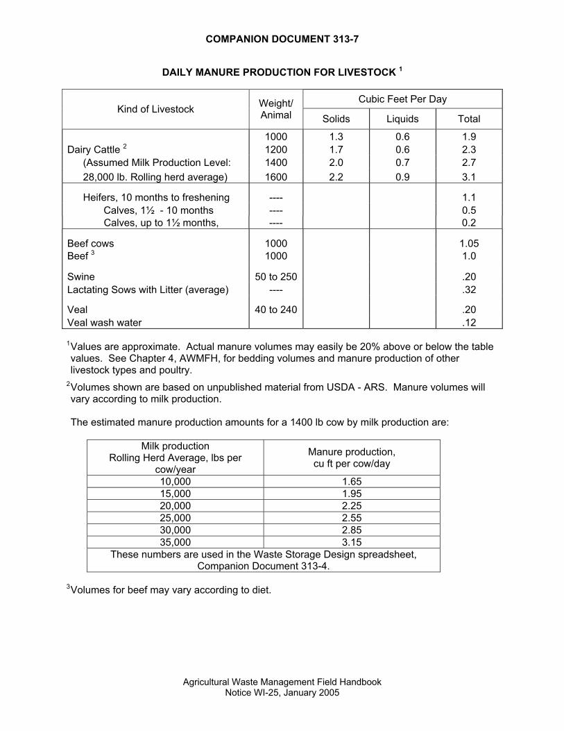
DAILY MANURE PRODUCTION FOR LIVESTOCK 1
Cubic Feet Per Day Kind of Livestock Weight/
Animal Solids Liquids Total
1000 1.3 0.6 1.9 Dairy Cattle 2 1200 1.7 0.6 2.3
(Assumed Milk Production Level: 1400 2.0 0.7 2.7 28,000 lb. Rolling herd average) 1600 2.2 0.9 3.1
Heifers, 10 months to freshening ---- 1.1 Calves, 1½ - 10 months ---- 0.5 Calves, up to 1½ months, ---- 0.2
Beef cows 1000 1.05 Beef 3 1000 1.0
Swine 50 to 250 .20 Lactating Sows with Litter (average) ---- .32
Veal 40 to 240 .20 Veal wash water .12
1 Values are approximate. Actual manure volumes may easily be 20% above or below the table values. See Chapter 4, AWMFH, for bedding volumes and manure production of other livestock types and poultry.
2 Volumes shown are based on unpublished material from USDA - ARS. Manure volumes will vary according to milk production. The estimated manure production amounts for a 1400 lb cow by milk production are:
Milk production
Rolling Herd Average, lbs per cow/year
Manure production, cu ft per cow/day
10,000 1.65 15,000 1.95 20,000 2.25 25,000 2.55 30,000 2.85 35,000 3.15
These numbers are used in the Waste Storage Design spreadsheet, Companion Document 313-4.
3 Volumes for beef may vary according to diet.
Agricultural Waste Management Field Handbook Notice WI-25, January 2005
COMPANION DOCUMENT 313-8
SAND BEDDING AND SAND LADEN MANURE (SLM) HANDLING
Bedding Clean, fine sand (concrete or mason sand) continues to be the bedding of choice for many farmers using freestall barns. The University of Wisconsin Extension staff and some veterinarians claim that sand is the best material for herd health and cleanliness. Cows seem to prefer it, and it helps reduce cow slipping in wet alleys. Sand is typically used at a rate of about 0.3 to 0.5 cubic feet per cow per day or 4 to 7 cubic yards per cow per year. If some type of retaining device is used to help keep the sand in the stalls, sand use can be reduced by about one third. If a fabric is used over the sand, very little sand is used, about 0.05 cubic foot per cow per day. Pump Transfer Most conventional style horizontal piston pumps don't do well with sand. Vertical piston pumps have shown more promise in recent years. Sand typically causes excessive wear on pumps and can cause premature pump failure. Distances up to 500 feet and 20 feet of lift have been achieved with vertical piston pumps. Chopper pumps can be successful, but considerable horse power may be necessary (40 to 100 HP). Also, impellers need to be changed once a year or so due to excessive wear. The challenge is getting and keeping the sand in suspension so that it can be pumped. Smaller reception pits are better in this regard. Larger reception tanks should have a method to remove sand accumulation without human entry, such as removable covers that allow access from above with a backhoe. Procedures outlined in ASABE EP 470, Manure Storage Safety, must be followed if entry is required. Pipelines may get plugged with sand. Some pump systems are installed with access points where compressed air can be applied in the pipelines at 200 to 400 foot intervals. Air pressure used in these systems can reach up to 140 psi. Relief valves should be set lower than 72% of the pressure rating of the pipe to avoid rupture. Pipeline cleanout ports spaced at no more than 150-foot intervals can assist greatly in unplugging a sand-filled pipeline. Gravity Transfer Gravity transfer can work in several configurations: 1. A narrow concrete channel (2 to 3 feet wide) that empties into a tower or “chimney” or large
diameter pipe can be used. The manure goes in the tower top and out the bottom below the manure level in the storage pond. The narrow channel may also empty into a reception tank where it is pumped to the storage facility. The sand that accumulates in the channel may need to be excavated frequently. One option is to install a cable drive unit on one end of the channel. Small scrapers or “boats” are attached to the cable at needed intervals. The boats operate like an alley scraper, pushing the sand to the tower, thus eliminating the need for manual sand removal. Another option for channel cleaning is the use of suspended augers. Cleaning narrow channels may also be done by removing the top lid or grates and using a small backhoe. Narrow concrete channels (2 to 3 feet wide) are generally better than large tanks (8 to 12 feet wide). The sandy manure moves through the narrower channels more quickly, and
Agricultural Waste Management Field Handbook Notice WI-31, April 2009
Companion Document 313–8
there isn’t as much time for the sand to settle. The top of the storage pond should be 4 to 6 feet minimum below the barn floor for best operation of this type of gravity flow system.
2. A reception tank with a guillotine valve at the entrance of a large diameter (24-inch) transfer pipe can be used to release the contents all at once. The reception tank is kept small so that the manure builds up fairly quickly (within a few days). The reception tank should be narrow and not over 100 feet long. A chopper pump can be included at the opposite end to agitate the manure and suspend the sand before the guillotine valve is pulled. Sand bedding should be carefully considered for use with this type of system. A vent pipe needs to be installed in this and all transfer pipes within ten feet of the reception tank.
Milking Center Waste or Water Water or milk house waste should not be added to sand-laden manure until you want it to settle. The water tends to wash the manure off the sand causing rapid sand settling. Water additions to the transfer system may be beneficial for gravity or pumped transfer systems that do not use sand bedding. Sand Settling Lanes Sand settling lanes are designed for flush flume barn systems with multiple stage storage ponds. The water for flume flushing is typically pumped out of the last manure pond stage to the barn. The sand-laden flush water flows to a long, nearly flat, concrete lane. The intent is to produce a velocity on the lane in which the sand will settle out, but the manure will remain suspended in the water which continues to a reception tank or first stage storage pond. The sand that has settled on the lane is then removed with a front loader and piled to the side. The pile of sand drains out some additional manure and water which flows back into the manure stream. Once dried, the sand is reused as bedding. Sand lanes were first built with a 1% slope. Designers discovered that flatter is better and most lanes are now built on a 0.25% slope. The target velocity for the flush water is around 1.5 fps, which allows for settling of sand particles larger than a #60 sieve. If the velocity is too high, less sand settling occurs. If the velocity is too low, manure settles out with the sand. Some claim that a settling efficiency of 90% can be achieved. Constructing parallel lanes will allow the operator to clean one lane while the other is in use. The use of two lanes may be unnecessary because some operators have found that it is best to remove the sand from the lanes while the flume is running. Mechanical Separators One type of separator uses an inclined auger to bring sand-laden manure to the separator. While in the separator, water and air bubbles separate the sand from the manure. The sand settles to the bottom of the separator and is transported out with a small auger. The sand is usually clean enough to reuse for bedding. The manure in suspension can be pumped or gravity transferred to a storage pond. Some claim that an efficiency of 90% can be achieved with this process, too. Storage Ponds Given several weeks of detention time, the sand will settle out from the manure. Therefore, manure storage should be done in two or three stages.
Stage 1: Sand settling pond. Size the pond to hold about 1.5 to 4 times the sand used for bedding. These ponds seem to operate best in a “full” condition with the
Agricultural Waste Management Field Handbook Notice WI-31, April 2009

COMPANION DOCUMENT 313–8
Agricultural Waste Management Field Handbook Notice WI-31, April 2009
liquid depth as great as possible. The transfer pipe from the barn to the pond should enter the pond as high as possible to allow sand to settle below the pipe without plugging the pipe outlet. Most ponds are paved and have an access ramp. Some farmers are trying hi-hoes or draglines to excavate the sand. A concrete surface will be required to facilitate cleaning and protect any pond liner. Others are using large agitators to bring the sand into suspension and then pumping it out. Sand is often difficult to keep in suspension when agitating the pond.
Stage 2: Manure pond. Manure will flow from stage 1 to stage 2 via a concrete channel or weir. It is best to use some type of open system, since pipes will plug with sand. The downstream slope (stage 2 side) of the transfer system will need to be protected from erosion, down to the bottom of the manure pond. Some sand removal may be necessary. Provisions for machinery entry and appropriate surfacing must be considered.
Stage 3: Pond for flush systems (optional). Liquid is pumped out of this pond and used to flush out the barn alleys.
Visit Existing Facilities Handling sand laden manure is an art. It's wise to visit some existing dairies to see what is working and not working before deciding on a particular system.

COMPANION DOCUMENT 313-9
Agricultural Waste ManagemeNotice WI-25, Janu
SEPA
RA
TIO
N D
ISTA
NC
E M
EASU
REM
ENT
TO S
ATU
RA
TIO
N A
ND
BED
RO
CK
Exi
stin
g G
roun
d
Sep
arat
ion
Dis
tanc
e In
side
S
urfa
ce
edro
ck
nt Field Handbook ary 2005
Sum
p
Sat
urat
ion
or B
Sep
arat
ion
Dis
tanc
e

COMPANION DOCUMENT 313-10
GEOMEMBRANE LINERS IN WASTE STORAGE FACILITIES
Gas Release and Intimate Contact There are documented instances where “whales” of gas have formed underneath synthetic liners and have been cause for concern. Installation of a permeable layer of material, such as sand/gravel, beneath the liner has been promoted as a means to prevent this situation. Installation of geomembrane over a geotextile or permeable material would allow a leak to flow unrestricted and distribute the leakage from a hole over a large area and create the greatest opportunity for contaminates to permeate to groundwater. However, this practice conflicts with the “intimate contact” theory of composite liner design. Geomembrane liners function best when they are combined with a slowly permeable subgrade foundation to form a “composite” liner. The soil component of the composite liner retards the rate of leakage, should the membrane component develop a hole or tear.
The current standard of practice for municipal landfill liner design is a 60-mil High Density Polyethylene (HDPE) geomembrane in “intimate contact” with 4 feet of recompacted clay with a permeability less than 1x10⁻⁷ cm/sec. “Intimate contact” means the geomembrane is placed directly on top of the clay, so that the clay is in a position to seal a leak in the membrane if one develops. The concept of “intimate contact” has been utilized in the standard, but the thickness of soil material below the liner is less than the 4 feet used for landfills.
Gas forming beneath geomembranes may result from decomposition of organic materials beneath the liner. The need for gas release is based on "gas generating subsurface conditions" per Robert M. Koerner's "Designing with Geosynthetics," 4th Edition, Prentice Hall, 1998. Sources of organic materials can include: (a) buried natural organic soils, (b) residual waste materials where an existing facility is being re-lined, (c) and leakage through a liner resulting from poor construction or improper operation. Strategies to control gas generation include removal of source materials where practical, and ensuring quality construction through selection of experienced, reputable contractors and/or continuous construction inspection and testing by an independent third party. Gas release shall be included in the design per standard 313. In order to preserve the benefits of a composite liner, the gas release system should be limited to narrow gravel trenches with vent pipes. These should be spaced beneath the liner in lieu of a permeable vent blanket beneath the entire liner. “Shirt pocket” vents on liner side slopes, although easy to construct, may be cause for concern because they could provide a conduit for wastes to get underneath the liner if the facility is not emptied in a timely fashion. These vents, if used, should be installed above the low point of the facility embankment so that waste or runoff will not reach the vents. Also, these vents installed over slowly permeable subgrade may be of little value in terms of releasing gas pressure because gas may not be able to reach the vent location.
Agricultural Waste Management Field Handbook Notice WI-27, December 2005

Companion Document 313-10
GEOMEMBRANE LINER INSPECTION PLAN (313-10A)
General - It has been shown, discussed, and documented in many places that geomembrane liners can provide a nearly impervious barrier to movement of pollutants into the environment provided they are properly installed and maintained. The attached inspection plan and forms represents a minimum reasonable amount of inspection and documentation recommended to ensure a quality job. Reasoning behind each of the elements of the inspection plan is as follows:
Submittals - One set of material test results for each batch of resin material used on the job should help ensure that a collection of roll scraps and odd lots are not used on the job; or at least it will be known if they are. If several different resin batches, or perhaps even different sheet manufacturers, are used on the project, then more attention should be paid to trial welding and laboratory seam testing to ensure that good welds are obtained.
Documentation that the subgrade was in suitable condition prior to deployment could be very important if a warranty claim will be submitted in the future.
Inspection - Continuous inspection should be required during all seaming and testing for two reasons; one, to provide an unbiased assurance that construction has been completed in accordance with plans and specifications, and two, to have a track record in order to do “forensic engineering” in the event a laboratory seam sample fails. When a lab sample fails, the total affected length of seam must be identified in some fashion. In order to do this, it must be known who welded what, where, and when. Locations along the same seam can be retested, but how does the inspector know that the seam prior to (or after) the seam being tested is good? If there are no records, then it may not be known where the prior (or subsequent) seam is at all. Good records can substantially reduce the amount of lab testing needed when a failure occurs.
Checking samples from each end of seams as they are completed is a good running check of the seaming equipment and settings. It will detect if a heating element fails, for example, and potentially prevent extensive seam repairs later.
In terms of repairs, it is useful to establish a sequential numbering system to track and document that all marked repairs are completed and tested. A typical frequency of repairs is about 40 per acre; so it is easy to miss needed repairs without some kind of tracking system.
Laboratory Seam Samples - This is required in Wisconsin Construction Specification 202. Field testing programs can and do miss substantial seam problems that are detected in the laboratory test. For example, if one element of a dual wedge welder fails during a seam, the resulting seam may pass an air test but would not be of sufficient strength. Also, if the sheet is not sufficiently cleansed prior to seaming, the seams may pass the air tests but may not be of sufficient strength. If the contractor knows that the seams will be subjected to even a minimal random laboratory testing program, the overall quality of the job is likely to increase.
Sketch - A sketch showing panel and seam numbers and repair locations is useful in keeping track of the documentation.
The following inspection plan can be utilized by adding the facility name, copied, and inserted into the overall site construction plan.
Agricultural Waste Management Field Handbook Notice WI-27, December 2005

Companion Document 313-10
GEOMEMBRANE LINER INSPECTION PLAN FOR
________________________________
1.0 Submittals - The geomembrane manufacturer shall submit roll test results which demonstrate that the material to be used meets requirements of the applicable Tables 1-4 of NRCS Wisconsin Construction Specification 202 - HDPE Geomembrane Lining. A minimum of one set of test results per resin batch used in the manufacture of the rolls to be used on the project shall be provided.
The installation contractor shall provide a written statement that the subgrade was in acceptable condition per manufacturer’s requirements immediately prior to panel deployment. This statement shall be provided prior to the installation contractor’s departure from the job site.
2.0 Inspection - Continuous inspection will be provided by a third party inspector (i.e. not affiliated with the contractor or owner) during panel deployment, panel seaming, seam testing, and repair testing. The inspector will observe and document that:
• trial welds are completed and demonstrate that the welding equipment is adjusted to obtain acceptable welds under climatic conditions present
• panels are seamed using welding machine settings set during the trial weld procedure
• one-inch wide samples from each end of each fusion seam fail by film tear bond when peeled apart using a pair of vise-grips or similar device
• air-channel tests or vacuum-box tests, as appropriate, are completed on all seams
• all repairs to seams or the liner are completed and pass the vacuum-box test
Results of the above observations will be recorded on the attached forms. Panels will be numbered consecutively, and seams will be identified by consecutive panels (i.e. Seam 1/2 joins panel 1 and panel 2). Any location on a seam or panel that requires an extrusion weld will be identified as a repair location.
3.0 Laboratory Seam Samples - At least one sample per 500 feet of seam, or one sample per welder/welding machine combination, whichever is greater, shall be cut from the liner and submitted to a laboratory for testing per ASTM D-4437. A specimen approximately 42 inch long (along the seam) by 12 inch wide (across the seam) shall be cut. A minimum of two peel tests from each end of the specimen shall be tested in the field to document that the sample is worthy of laboratory analysis. If the field peel tests pass, the specimen shall be divided into three 12 inch samples, distributed as follows:
• one sample to be submitted to the laboratory for analysis per ASTM D-4437
• one sample to the geomembrane installer for independent testing, if desired by the installer
• one sample to the owner for archive purposes
Agricultural Waste Management Field Handbook Notice WI-27, December 2005

Companion Document 313-10
Agricultural Waste Management Field Handbook Notice WI-27, December 2005
Should a laboratory seam sample fail the test, the affected seam shall be retested and/or repaired in such a manner that the failed test is bounded in both directions by passing laboratory tests. The contractor will be given the option of “stepping out” in both directions a minimum of 10 feet and submitting further samples for laboratory testing, or repairing by capping all seams produced by the welder/welding machine combination.
4.0 Acceptance - The liner will be accepted when it has been documented that all seams and repairs have been tested and found acceptable, that all laboratory test results have passed, and that a final walkover shows that no additional repairs and tests are needed.
5.0 Documentation - Documentation will consist of manufacturer material submittals, contractor subgrade acceptance statement, completed trial weld, panel seaming, seam testing, and repair summary forms, and a sketch showing as-constructed panel layout with panel numbers, seam numbers, repair numbers, and laboratory test locations.

Companion Document 313-10
Agricultural Waste Management Field Handbook Notice WI-27, December 2005
USDA - Natural Resources Conservation Service Trial Weld Summary Project: _____________________________ Technician: _______________________________
PEEL (ppi) Shear (ppi) Outside Track Inside Track Test
No. Date
Time (AM/ PM)
Temp. (deg F)
Welder ID
MachineNumber
Temp.Setting/Speed
Weld Type 1 2 3 1 2 3 1 2
Test Result(P/F)
Material Type/ Comments

Companion Document 313-10
Agricultural Waste Management Field Handbook Notice WI-27, December 2005
USDA - Natural Resources Conservation Service Panel Seaming Summary Project: _____________________________ Technician: ______________________________
Seam End Test Results Seam
No. Date Start Time
Weather (clouds/
sun)
Ambient Temp. (deg F)
Welder ID
MachineNumber
Temp. Setting/ Speed
Weld Type
Seam Length
(ft) Begin End Material Type/
Comments

Companion Document 313-10
Agricultural Waste Management Field Handbook Notice WI-27, December 2005
USDA - Natural Resources Conservation Service Seam Test Summary Project: _____________________________ Technician: _________________________________
Air Test Vacuum Test Start End Seam
No. Distance Date PSI Time PSI Time Pass/Fail Date
Pass/ Fail Comments

Companion Document 313-10
Agricultural Waste Management Field Handbook Notice WI-27, December 2005
USDA - Natural Resources Conservation Service Repair Summary Project: _____________________________ Technician: ________________________________
Repair No. Date Time
Welder ID
Machine Number Repair Location Description
Size of
Repair
VacuumBox Date
Test Results
(P/F)

COMPANION DOCUMENT 313-11
CONCRETE JOINTS - CONSTRUCTION, CONTROL, EXPANSION, ISOLATION
Joint Type Purpose
Contraction Joints To control cracking
Isolation Joints To isolate a concrete structure from other structures
Expansion Joints To provide for expansion of the concrete
Construction Joints To improve ease of construction Contraction (Control) - Contraction joints are used to control the location of cracks caused by concrete shrinkage during setting and thermal changes. Cracking is usually controlled by reducing the concrete thickness 25% at the desired crack locations. The thickness is reduced by sawing, hand groovers, preformed joint material, or removable strips of wood or metal. The non-structural reinforcing steel is usually carried through these joints - especially in slabs. Saw cut TYPICAL CONTRACTION JOINT Isolation - This joint is used to isolate structural units that exhibit differential horizontal and/or vertical movement. There is no steel or dowels crossing the joint. There is seldom a need for these joints except adjacent to buildings, silos, etc. Expansion - These joints are used to prevent crushing of abutting concrete or other structural units due to compressive forces developed during expansion caused by heat. These joints are usually doweled such that movement can be accommodated in one direction, but there is shear transfer in the other directions. These joints are often used in road construction, especially adjacent to bridges, but they are seldom used in conservation work. Construction - These joints are used where a fresh pour of concrete abuts an existing one. Not all concrete in a given structure can be placed continuously, so there are construction joints that allow for work to be resumed after a period of time. Placement of these joints can be predetermined or as needed on the job. In conservation work these joints are primarily used at the base of concrete walls, in large slabs, and in long walls. The first pour stops, and after a day or more there is a second pour. The concrete is held tightly together, and there will be little or no leakage through the joint. Reinforcing steel may or may not be carried through a construction joint. If the steel is carried through the joint, the joint is monolithic and considered to be liquid tight. Examples of these monolithic joints are joints at the base of T walls and joints in slabs where the steel extends through the joint. If the steel is not carried through the joint, a waterstop must be used if the joint needs to be liquid tight.
Companion Document 313-11
Agricultural Waste Management Field Handbook Notice WI-25, January 2005
Joints that serve more than one purpose - Often joints are designed to do several things such as control cracking and serve as a construction joint. In this case most of the steel will not be carried through the joint because it is preferable for the concrete to crack at that location. Liquid tight joints - Often it is desirable to have joints be liquid tight. Here are some examples:
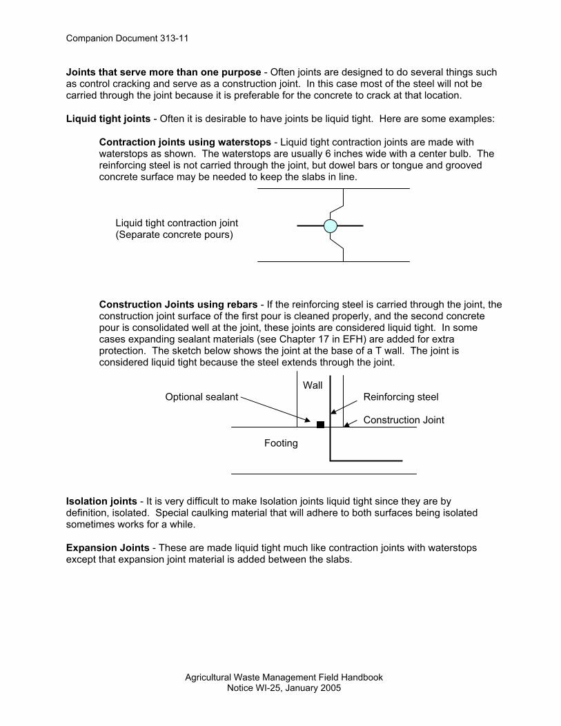
Contraction joints using waterstops - Liquid tight contraction joints are made with waterstops as shown. The waterstops are usually 6 inches wide with a center bulb. The reinforcing steel is not carried through the joint, but dowel bars or tongue and grooved concrete surface may be needed to keep the slabs in line.
Liquid tight contraction joint (Separate concrete pours)
Construction Joints using rebars - If the reinforcing steel is carried through the joint, the construction joint surface of the first pour is cleaned properly, and the second concrete pour is consolidated well at the joint, these joints are considered liquid tight. In some cases expanding sealant materials (see Chapter 17 in EFH) are added for extra protection. The sketch below shows the joint at the base of a T wall. The joint is considered liquid tight because the steel extends through the joint. Wall Optional sealant Reinforcing steel Construction Joint Footing
Isolation joints - It is very difficult to make Isolation joints liquid tight since they are by definition, isolated. Special caulking material that will adhere to both surfaces being isolated sometimes works for a while.
Expansion Joints - These are made liquid tight much like contraction joints with waterstops except that expansion joint material is added between the slabs.
COMPANION DOCUMENT 313-12
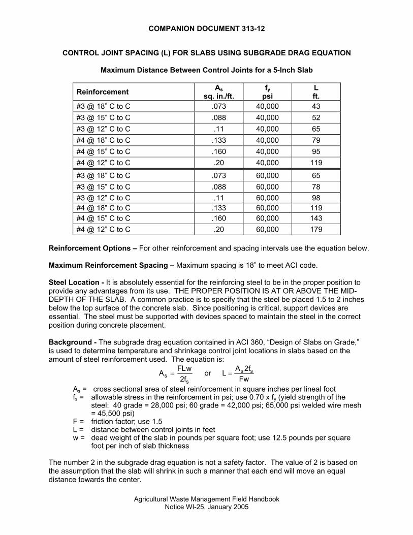
CONTROL JOINT SPACING (L) FOR SLABS USING SUBGRADE DRAG EQUATION
Maximum Distance Between Control Joints for a 5-Inch Slab
Reinforcement As sq. in./ft.
fy psi
L ft.
#3 @ 18” C to C .073 40,000 43 #3 @ 15” C to C .088 40,000 52 #3 @ 12” C to C .11 40,000 65 #4 @ 18” C to C .133 40,000 79 #4 @ 15” C to C .160 40,000 95 #4 @ 12” C to C .20 40,000 119
#3 @ 18” C to C .073 60,000 65 #3 @ 15” C to C .088 60,000 78 #3 @ 12” C to C .11 60,000 98 #4 @ 18” C to C .133 60,000 119 #4 @ 15” C to C .160 60,000 143 #4 @ 12” C to C .20 60,000 179
Reinforcement Options – For other reinforcement and spacing intervals use the equation below. Maximum Reinforcement Spacing – Maximum spacing is 18” to meet ACI code. Steel Location - It is absolutely essential for the reinforcing steel to be in the proper position to provide any advantages from its use. THE PROPER POSITION IS AT OR ABOVE THE MID-DEPTH OF THE SLAB. A common practice is to specify that the steel be placed 1.5 to 2 inches below the top surface of the concrete slab. Since positioning is critical, support devices are essential. The steel must be supported with devices spaced to maintain the steel in the correct position during concrete placement. Background - The subgrade drag equation contained in ACI 360, “Design of Slabs on Grade,” is used to determine temperature and shrinkage control joint locations in slabs based on the amount of steel reinforcement used. The equation is:
A FLwfss
=2
or L A fFws s=2
As = cross sectional area of steel reinforcement in square inches per lineal foot fs = allowable stress in the reinforcement in psi; use 0.70 x fy (yield strength of the
steel: 40 grade = 28,000 psi; 60 grade = 42,000 psi; 65,000 psi welded wire mesh = 45,500 psi)
F = friction factor; use 1.5 L = distance between control joints in feet w = dead weight of the slab in pounds per square foot; use 12.5 pounds per square
foot per inch of slab thickness The number 2 in the subgrade drag equation is not a safety factor. The value of 2 is based on the assumption that the slab will shrink in such a manner that each end will move an equal distance towards the center.
Agricultural Waste Management Field Handbook Notice WI-25, January 2005
COMPANION DOCUMENT 313-13
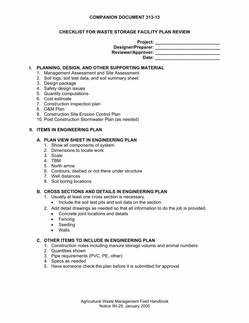
CHECKLIST FOR WASTE STORAGE FACILITY PLAN REVIEW
Project: __________________________ Designer/Preparer: __________________________
Reviewer/Approver: __________________________ Date: __________________________
I. PLANNING, DESIGN, AND OTHER SUPPORTING MATERIAL
1. Management Assessment and Site Assessment 2. Soil logs, soil test data, and soil summary sheet 3. Design package 4. Safety design issues 5. Quantity computations 6. Cost estimate 7. Construction Inspection plan 8. O&M Plan 9. Construction Site Erosion Control Plan 10. Post Construction Stormwater Plan (as needed)
II. ITEMS IN ENGINEERING PLAN
A. PLAN VIEW SHEET IN ENGINEERING PLAN 1. Show all components of system 2. Dimensions to locate work 3. Scale 4. TBM 5. North arrow 6. Contours, dashed or not there under structure 7. Well distances 8. Soil boring locations
B. CROSS SECTIONS AND DETAILS IN ENGINEERING PLAN
1. Usually at least one cross section is necessary. • Include the soil test pits and soil data on the section.
2. Add detail drawings as needed so that all information to do the job is provided. • Concrete joint locations and details • Fencing • Seeding • Walls
C. OTHER ITEMS TO INCLUDE IN ENGINEERING PLAN
1. Construction notes including manure storage volume and animal numbers 2. Quantities shown 3. Pipe requirements (PVC, PE, other) 4. Specs as needed 5. Have someone check the plan before it is submitted for approval
Agricultural Waste Management Field Handbook Notice WI-25, January 2005

COMPANION DOCUMENT 313-14
CLAY LINERS
Installation
See Wisconsin Construction Specifications 204 and 300 for clay liner installation requirements. Note that compaction requirements for liners are different than for manure storage embankments. Liners on slopes can be installed horizontally or parallel with the slope. Horizontal liners must be wide enough to accommodate the compaction equipment. Liners parallel with the slope must be flat enough for the compaction equipment to work safely and effectively. Generally this will mean 2½ : 1 or flatter. Horizontal Widths
Thickness Slope Horizontal Width 2:1 6’ - 8”
3’ 2 ½:1 8’ - 1” 3:1 9’ - 6” 2:1 8’ - 11”
4’ 2 ½:1 10’ - 9” 3:1 12’ - 8” 2:1 11’ - 2”
5’ 2 ½:1 13’ - 7” 3:1 15’ - 10”
θsin Thickness =Width
z 1 tan= θ 1-
H
1
T s
A
hicknes
gricultural Waste ManagemNotice WI-25, Janu
Side Slope(z)
orizontal Width
θ
enar
t Field Handbook y 2005

Companion Document 313-14
Molding Water Content For natural soils, the degree of saturation of the soil liner material at the time of compaction is perhaps the single most important variable that controls the engineering properties of the compacted material. The typical relationship between hydraulic conductivity and molding water content is shown in Figure 1. Soils compacted at water contents less than optimum (dry of optimum) tend to have a relatively high hydraulic conductivity; soils compacted at water contents greater than optimum (wet of optimum) tend to have a low hydraulic conductivity and low strength. For some soils, the water content relative to the plastic limit (which is the water content of the soil when the soil is at the boundary between being a solid and plastic material) may indicate the degree to which the soil can be compacted to yield low hydraulic conductivity. In general, if the water content is greater than the plastic limit, the soil is in a plastic state and should be capable of being remolded into a low-hydraulic-conductivity material. Soils with water contents dry of the plastic limit will exhibit very little “plasticity” and may be difficult to compact into a low-hydraulic-conductivity mass without delivering enormous compactive energy to the soil. Extra compactive effort can overcome some dryness, but it is best to use moist soil.
FIGURE 1
EFFECT OF MOLDING WATER CONTENT ON HYDRAULIC CONDUCTIVITY
Agricultural Waste Management Field Handbook Notice WI-25, January 2005

COMPANION DOCUMENT 313-15
SUMPS IN WASTE STORAGE FACILITIES
Most manure pits need a sump to facilitate emptying. In-place earth (313 Table 1) manure storage facilities often utilize a 20 feet by 20 feet by 2 feet sump or a 2 feet trough all along one side of a pit. The sump must be paved if there is less than 6 to 8 feet of soil meeting the criteria in Table 1 below the floor elevation of the manure storage facility. (See “Scour Protetction”)
Sumps in clay lined impoundments or those close to bedrock or the water table will need to be liquid-tight concrete. An apron is needed around it to reduce the chance for seepage under the concrete. Reinforcing steel is placed to meet Table 5, Footnote 2 and a 5 foot apron is used around the sump. Note that there is no sand/gravel below the concrete. Sand/gravel would promote seepage.
CONCRETE SUMP IN CLAY LINED IMPOUNDMENT
5 ft. 2 ft. deep, max Intimate contact between concrete and clay Bottom of clay liner 12 ft. wide Concrete and steel reinforcing must to be as stated in Note 2 of Table 5 in 313.
Agricultural Waste Management Field Handbook Notice WI-25, January 2005

COMPANION DOCUMENT 313-16
SATURATION, HOW TO HANDLE IT
This is further discussion regarding saturation as set forth in Standard 313, Section V.A.10 and in Tables 1 through 6 and Table 9.
Saturation can come in a number of different forms. The Regional Water Table is defined in the standard. It can't be lowered by drainage, so it won’t be dealt with further here. Confined lenses and perched water are also defined, but they can be manipulated. The material below suggests some ways to treat them.
Confined lenses - These lenses range from layers of sands or gravel to discontinuities between glacial tills laid down at different times. The lenses of sand or gravel often carry a large volume of water while the discontinuities may only have very slow seeps. In either case, the lens needs to be dug out to the separation distance as shown in Tables 1 through 6 and 9. Assuming the lens is continuous through the facility, it will have to be dug out and backfilled all the way around the facility. Backfill specifications are found in Wisconsin Construction Specification 204, Earthfill for Waste Storage Facilities.
The lenses carrying a fairly large amount of water will need interception and an outlet. This is usually done with a combination of sand or gravel and tile to a free outlet or another tile line. Whether to just plug up the lens or to install a drainage system is a difficult design question. Factors to consider include: thickness of lens, slope of upstream land, slope of lens, elevation of lens relative to storage facility, grain size of material in lens, amount of fines in lens material, time of year, recent weather, and flow coming from the lens. The designer must make the decision based on consideration of these factors and knowledge of the local geology. See the sketch for a typical drain installation.
Locate drain 313 Table 1 storage facilities - Dig out the lens near outside of and backfill. Backfill material must meet Embankment toe. Table 1 criteria and must be compacted according to Spec 204 criteria. Existing Ground Groundwater Flow 1:1 max slope Drain Fill Water bearing lens Tile to free Outlet Separation Distance Note: Tile might only be needed on the upstream side(s) of a storage facility constructed on sloping ground, or it might be needed all the way around.
Agricultural Waste Management Field Handbook Notice WI-25, January 2005

Companion Document 313-16
Agricultural Waste Management Field Handbook Notice WI-25, January 2005
Pockets of sand and gravel - Some seeps in test pits may actually be from pockets of sand or gravel rather than continuous lenses. Sometimes the seepage will start heavy and slow appreciably after a few minutes or hours. These pockets need to be dug out and backfilled like the lenses, but a separate drainage system will not be necessary.
Perched conditions - Often soils will be poorly or somewhat poorly drained due to the tight soil below the root zone. These are often good locations for earthen manure storage because the soils will also work well to contain the manure. However, the top 3 feet or so of soil will probably have pretty good structure due to root action, frost action, and the clay in the soil, so water may move laterally in the soil and outlet into the storage facility. The same soil could permit seepage out as well. This soil should be removed and backfilled according to the separation distances in 313 Tables 1 through 6 and 9 just like the lenses. Usually these perched conditions will not require drainage facilities, but if a drain is desired, the same design as for lenses can be used.

COMPANION DOCUMENT 313-17
STANDARD DESIGNS FOR REINFORCED CONCRETE WALLS GUIDE FOR USE
Introduction
The Wisconsin series of reinforced concrete wall standard drawings are intended to be applied to conservation projects within the conditions and limitations specified for each drawing. The standard drawings do not constitute a facility or project design; rather they can be used as a component of the facility or project design. The use of these standard drawings is intended for qualified engineers or conservation technicians with corresponding levels of DATCP Certification or NRCS Job Approval. Their use requires a working knowledge of structural engineering principals, the technical standards associated with the intended practice, and any applicable codes and regulations. Persons using these standard drawings assume responsibility for their appropriate application including their intended use and anticipated loading. The reinforced concrete standard wall drawings are developed using the ultimate strength method, and are consistent with ACI 318-99. Documentation for the drawings is on file with the NRCS State Conservation Engineer.
Wisconsin Standard Drawings are available on the Wisconsin NRCS web page located at http://www.wi.nrcs.usda.gov/technical/enghome.asp.
General
Foundation Soils: The foundation soil shall provide at least 2,000 psf bearing capacity. Presumptive bearing strength values for various soils are contained in Table A, Standard 313, Waste Storage Facility. Foundation soils of questionable bearing capacity or stability should undergo a geotechnical investigation to a minimum depth of 10 feet below the planned bottom elevation of the footing.
Locating reinforced concrete walls on fill is discouraged due to the probability of settlement. Design of earthfill below concrete walls shall be done by a qualified engineer.
Saturation: These wall drawings are not designed to withstand the loads imposed by saturated soils. Surface water drainage shall be diverted away from the walls. Subsurface water shall be intercepted and carried to a suitable gravity outlet. For wall drawings used in manure storage facilities, separation distances for subsurface water shall be provided in accordance with Standard 313.
Frost Protection: Frost protection shall be addressed within the facility or project design. Backfill to a height of 2 feet or more above the footing is recommended for frost protection where practical and consistent with the design parameters.
Cost Effective Design: Understanding the site and use conditions will allow for the selection of the most economical wall drawing. The addition of slabs to reduce machinery surcharge loads, the use of an alternate backfill material, and adjustments to the backfill height, are all design options that can be used to achieve the most economical facility design.
A cost-effective facility design may include multiple standard wall drawings for different wall segments, provided that the wall drawings match the anticipated conditions and are practical to construct.
Agricultural Waste Management Field Handbook Notice WI-25, January 2005

Companion Document 313-17
Roofs and Buildings: Buildings and other structures attached to walls can impose loads that are not accommodated by the drawing design. With the exception of the structural slab and push-off, shown in Drawings WI-590 and WI-591, no other structural attachments are to be made without further design analysis.
Wall Selection
All of the following factors must be evaluated in the selection of a standard wall drawing.
Height: Wall height is selected based on use and site conditions. The series of wall drawings is organized according to 4-, 6-, and 8-foot heights. One standard drawing is available for 10-foot walls. The wall drawings are accompanied by “Guide for Selection” drawings (Drawings WI-540, WI-560, WI-580 or WI-592) that are differentiated further by backfill height, backfill soils, and machinery surcharge.
Backfill Height: The selected backfill height will influence the potential loading and sliding restraint. Backfill height cannot be altered beyond the design parameters without further design analysis. Backfill requirements shall be included in the construction plans and Operation and Maintenance Plan for the facility or system.
Backfill Soils: The texture of the backfill soils, expressed as percent fines (soils passing the #200 sieve), shall be established for wall selection in accordance to the “Guide for Selection” (Drawings WI-540, WI-560, WI-580, or WI-592, as appropriate). Backfill shall be placed in accordance with Wisconsin Construction Specification 3, Earthfill.
Machinery Surcharge: Wall selection must account for the additional earth pressure exerted by potential machinery traffic adjacent to the wall, as illustrated in Drawing WI-540, WI-560, WI-580, or WI-592, as appropriate. All walls or portions of walls, that are backfilled within one foot of the top shall be evaluated for potential machinery loading. Structural and nonstructural slabs can be included in a wall system to reduce the machinery surcharge. Limitations on machinery operation shall be included in the Operation and Maintenance Plan. Grass mowing equipment weighing 2,000 pounds or less is exempt from machinery surcharge limitations.
Use: The intended use of the wall will determine the potential loading and direction of the limiting load.
The selection process for 4-foot through 8-foot walls is different from the selection process for the 10-foot wall. For the 4-foot through 8-foot walls, the loading conditions are determined and then a wall design is selected to support the load. For the 10-foot wall, one design is available which will work for many, but not all, loading conditions. Thus, the process for the 10-foot wall is to check to see if the one available wall drawing will support the required load. If it will not, then there is not a standard design available, and a custom design must be completed.
Concrete Wall Sliding Restraint
Concrete wall standard drawings are based on retaining wall design procedures. A portion of this design procedure requires that retaining walls must be designed to resist lateral sliding. The lateral forces of the loads are resisted by the friction forces on the bottom of the footing and by opposing forces on the side of the footing and any keyways below the footing.
Agricultural Waste Management Field Handbook Notice WI-25, January 2005

Companion Document 313-17
When retaining walls are used for manure storage, either the backfill pushes on the wall when the manure level is low or the manure pushes on the wall when the backfill height is low. In either case, the wall must be restrained from sliding due to these loadings.
If the wall(s) is only backfilled a small amount, the major load will be from the manure contained in the facility. In these cases, a sliding restraint will be provided if the slab and wall footing are poured as a unit. Notice from the standard drawings that the slab steel overlaps the footing steel at least 12 inches. If the slab and wall footing are to be poured separately, the wall will have to be analyzed specifically for sliding with appropriate restraint provided.
Walls can be restrained from sliding in a number of ways.
One method to provide restraint is the use of a slab. Tables (Drawings WI-540B, WI-560B, WI-580B, and WI-593) show the minimum slab length required to restrain the wall in various loading conditions.
Minimum slab length When a retaining wall is used in a manure storage facility, the slab between the walls and the backfill on the opposing wall will usually restrain both walls from outside forces.
Tank Width
Backfill
Backfill
Difference < 2 ft If there isn’t a slab and opposing wall, there are other ways to restrain the walls: • When a retaining wall is used for earth, a keyway is typically placed below the footing.
Keyway
Agricultural Waste Management Field Handbook Notice WI-25, January 2005

Companion Document 313-17
Agricultural Waste Management Field Handbook Notice WI-25, January 2005
In some cases the wall footing can be buried somewhat to provide resistance like a keyway.
Bottom of Earthen Storage FacilityBackfill
• In some cases the heel of the wall footing can be lengthened to provide more soil backfill
weight on the footing.
Backfill
Extended Heel
• Where walls are not too long, it may be effective to use walls at right angles to help with
sliding.
Plan View
Walls at Right Angles
If minimum restraining slab requirements cannot be met, consult with a qualified engineer for assistance regarding design of sliding restraint using keyways, backfill, heel extensions, or walls at right angles.

COMPANION DOCUMENT 313-18
JOINING IMPOUNDMENT LINERS 1. In-place earth (Table 1) to clay liners (Table 2)
An important issue with this combination is determining where the in-place soil no longer meets the criteria. If this type of combination is being considered, extra soils investigation will be needed in the area where the soil is changing. Once the location of the changing soil has been determined, the clay liner should extend at least 10 feet into the acceptable in-place soil:
Inside surface of waste storage facility Clay liner Acceptable in-place Unacceptable in-place soil soil Transition between acceptable and unacceptable in-place soil 10 feet min.
The method of determining the location of the acceptable soil and the method of joining the in-place soil and clay liner shall be shown in the construction plan and shall be documented in the as built plan.
2. Geosynthetic (Table 3) to concrete (Table 5)
HDPE is joined to concrete using the embedment strip details shown in Wisconsin standard drawings. A wide “U” shaped piece of HDPE is inserted up side down in the concrete, and the HDPE liner is later welded to the HDPE strip on the concrete surface.
3. Concrete (Table 5) to in-place earth (Table 1)
The joining of concrete and in-place earth is similar to the joining of in-place earth and a clay liner. First it must be determined where the in-place soil no longer meets the criteria in Table 1. Once this has been determined the concrete liner should extend a minimum of 10 feet over the acceptable in-place soil. The concrete must be placed directly on the existing soil (intimate contact) with no sand/gravel under the concrete.
The details of how the acceptable soil is determined and how the concrete and in-place soil are joined shall be shown in the construction plan and shall be documented in the as built plan. 10’ min. Concrete liner
Acceptable in-place soil Unacceptable in-place soil
Agricultural Waste Management Field Handbook Notice WI-25, January 2005

Companion Document 313-18
Agricultural Waste Management Field Handbook Notice WI-25, January 2005
4. Concrete Liner (Table 5) to Clay Liner (Table 2) The joining of these two liners is similar to the other liners- namely a 10 foot overlap with no sand/gravel underneath the concrete:
Concrete liner Inside surface of waste storage facility 1:1 or flatter Clay liner Non-liner soil 10 feet min. 5. Concrete Wall to Clay Liner
For a concrete wall meeting a clay liner on the side of the pond the flow path between the clay liner and concrete wall or footing surfaces shall be a minimum of 10 feet before non-liner soil is encountered. This will mean extra clay adjacent to the wall since a 5 foot thick liner abutting a wall will only have a 5 foot contact flow path.
6. Concrete Wall Footing to Clay Liner
Again we need a 10 foot minimum flow path. Concrete Wall
Extra slab Non-liner Soil Clay liner 10 feet, min

COMPANION DOCUMENTS 313-19
KARST INFORMATION For review of the articles cited below and for other materials regarding sinkholes and other Karst features, contact the NRCS State Conservation Engineer REFERENCE, COMMENTS, AND DISCUSSION Sinkholes don't tend to occur in areas covered by more recent glaciers. Here are two quotes from Circular 968 (Development of Sinkholes Resulting From Man's Activities in the Eastern United States, by USGS, 1986):
P. 6, "States underlain by carbonate rocks that have been least affected by recent sinkhole development are located in areas affected by ancient glaciers (fig. 4). Most underground openings that might ultimately have caused sinkholes to form in these areas were either destroyed by the ice, filled with glacial debris, or covered with thick glacial deposits." P. 39, "Available information shows that the impact of sinkholes has been most significant in Alabama, Florida, Georgia, Missouri, Pennsylvania, and Tennessee. States with the least impact are located in areas formerly covered by glaciers." See the maps on page 7 (Fig. 4) and page 5. Very few mapped sinkholes have occurred in the glacial areas.
Sinkholes tend to occur in groups. - USGS Circular 968 talks about these groups on page 6. - Calvin Alexander at the University of Minnesota has extensively studied sinkholes in SE
Minnesota and has mapped existing sinkholes and the development of new sinkholes. He feels that the best and only predictive tool for the location of new sinkholes is that they will develop near existing sinkholes and especially near other recently developed sinkholes.
Sinkholes tend to develop in areas where the water table is drawn down such as near quarries. See page 36 of Circular 968. Naturally developing sinkholes need the lowered water table to promote seepage flow volume and velocity. Both help dissolve the carbonate rock and lead to sinkholes. This probably helps explain why there are many sinkholes in Pierce County, where the bedrock surface is often 50 to 100 feet above the water table, and virtually none in Winnebago and Outagamie Counties where the water table is often above the surface of the bedrock. It's the same bedrock formation in all three counties. Impoundment of water over carbonate rock can lead to sinkhole development due to the additional water and gravitational head. However, manure storage ponds having at least 1 % solids (DeTar, 1977) don't pose the same problem. The manure helps seal the soil and reduce permeability so that infiltration below manure storage ponds is less than in the soil adjacent to the ponds (Miller et al, 1985). Therefore, the tendency for sinkhole development, other things being equal, is less below manure storage ponds. The conclusions in Circular 968 regarding the influence of glaciers on sinkhole development seem to be born out in Wisconsin where the incidence of sinkholes are fairly small and where most of them are in areas that weren't covered recently by glaciers (referred to as the “driftless” area) or in areas of considerable relief and thin glacial deposits, such as Pierce and St. Croix Counties. Also, Pierce and St. Croix counties have the St. Peter sandstone formation over the Prairie du
Agricultural Waste Management Field Handbook Notice 210-WI-25, January 2005

Companion Document 313-19
Chien dolomite formation. This is the same situation as in SE Minnesota where at least three municipal sewage effluent ponds have failed (solids less than 1%). Significantly, the most numerous Karst features mapped in Pierce County are in the areas where the St. Peter sandstone overlies the Prairie du Chien dolomite. The most recent glaciers covered the non-driftless part of the state within the last 10,000 to 50,000 years. Much of the glacial till deposited by these glaciers has enough clay to reduce soil permeability and to hold fines in place when any water does move through the clay. This characteristic helps tile drainage work well in eastern glacial clay till soils. The few large sinkholes in the eastern part of the state are quite stable and drain quite large areas, sometimes several square miles. Hundreds of manure pits have been dug in these soils during the last 25 years, and no known problems due to sinkhole development have occurred. Many of these manure pits, certainly many dozen, have been within 3 to 10 feet of carbonate bedrock, and some have been directly bottomed on the Niagara dolomite formation without sudden failure due to loss of manure. The manure seems to both help seal the soil and to help plug any minor seeps that may occur. This is not surprising since virtually all the literature shows a significant (1 to 2 orders of magnitude) reduction of soil permeability by manure, and several researchers, Hills and DeTar, have noted that piping holes in the soil in their research experiments have been quickly sealed by manure. ANALYSIS IN RELATION TO MANURE STORAGE FACILITIES Carbonate bedrock and the associated Karst features pose two types of problems for manure pit construction: 1. Groundwater movement in the bedrock can be very fast, so pollutants can move very quickly
and have relatively low attenuation once they get into the bedrock. 2. Sinkholes can open up quickly and potentially cause catastrophic failure of the pit.
Fortunately, favorable circumstances exist in Wisconsin.
- Glaciers have cleaned and collapsed the bedrock and filled crevices. - Soils over much of the carbonate bedrock have fairly high plasticity and clay content. - Sinkholes, while present, are not as numerous and not as actively changing as in other
parts of the country. With these considerations in mind, the planning and design for manure pits over carbonate bedrock should include the following: 1. Map all sinkholes within 1000 feet of the proposed storage. 2. Stay 400 feet away from any sinkhole unless storage is concrete and above ground. 3. The design should exceed minimums where critical Karst conditions are found. Critical site
conditions include:
- density of sinkholes nearby. - new sinkholes opening up nearby - elevations of proposed pit floor and bedrock below it similar to elevations of bedrock
surface of nearby sinkholes.
Agricultural Waste Management Field Handbook Notice 210-WI-25, January 2005
Companion Document 313-19
Agricultural Waste Management Field Handbook Notice 210-WI-25, January 2005
4. Counties having areas of carbonate bedrock should map known sinkholes and other Karst
features and should show areas of the county, if any, that are unacceptable for earthen manure storage due to a preponderance of sinkholes and other Karst features.
5. A number of counties and regions of the state have maps and booklets of Pleistocene geology
and bedrock geology. To obtain available maps, contact the Wisconsin Geological and Natural History Survey at 3817 Mineral Point Road, Madison, WI 53705-5100; phone: 608-263-7389.
6. When Karst features are encountered such as sinkholes, disappearing streams, and caves;
Karst Inventory forms should be filled out and sent to the Wisconsin Geological and Natural History Survey. The form is available at this web address:
http:www.uwex.edu/wgnhs/pdfs/miscpdf/karstform.pdf