Embed Size (px)
Citation preview
•
•
•
StairMaster
OWNER'S MANUAL
StairMasterTHE WORKOUT OF yam UFE
StairMasler, Inc.• 6015 North Xanlhus Avenue. Tulsa, Oklahoma 74130 • (918) 425-5588 • (800) 331-3578
Table of Contents
• CONGRATUlATIONS... 3
SPECIFICAnONS 3
INsT'AUATION 3
PROPER CUMBING TECHNIQUES 3
INTRODUCTION 4
WARNINGS 5
BENEFITS 6
COMPUTER BASICS 6
1. Attract Mode 6
2. Data Entry 7
3. Exercise 7, 4. Exercise Summary and Goal Complete 7
OPERATION 7
1. Scrolling Message 8
2. Character Table 8
3. Changing The Workout Time 9
4. Custom Programs 9
5 Jackpot Option 10
6. Display Check 11
7. Code Summary -11
rnEORY OF OPERATION 12
MAINTENANCE 12
1. Removal of Side Panels 12
2. Bearing and Stepshaft Replacement 12
·1·
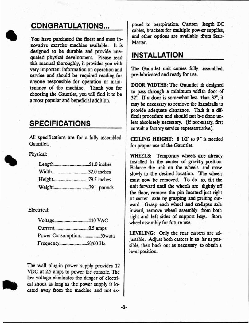
•CONGRATULATIONS...
You have purchased the finest and most innovative exercise machine available. It isdesigned to be durable and provide unequaled physical development Please readthis manual thoroughly, it provides you withvery important information on operation andservice and should be required reading foranyone responsible for operation or maintenance of the machine. Thank you forchoosing the Gauntlet, you will find it to bea most popular and beneficial addition.
SPECIFICATIONS
All specifications are for a fully assembledGauntlet.
Physical:
Length 51.0 inchesWidth 32.0 inches
Height. 79.5 inches
Weight 391 pounds
Electrical:
Voltage l10 VAC
CUrrent O.5 aIIlpS
Power Consumption .55wattsFrequency 50/60 Hz
The wall plug-in power· supply provides 12VDC at 2.5 amps to power the console. Thelow voltage eliminates the danger of electriCal shock as long as the.power supply is located away from the machine and not ex-
·3·
posed to perspiration. Custom length DCcables, brackets for multiple power supplies,and other optionS are available :from StairMaster.
INSTALLATION
The Gauntlet unit comes fully assembled,pre-lubricated and ready for use.
DOOR WIDTIiS: The Gauntlet is designedto pass through a minimum width door of32". H a door is somewhat less 'than 32", itmay be necessary to remove the handrails toprovide adequate clearance. Tb..is is a difficult procedure and should not ~c done unless absolutely necessary. (If necessary, firstconsult a factory service representative).
CEIUNG HEIGHT: 8 1/2' to 9' is neededfor proper use of the Gauntlet.
WHEELS: Temporary wheels are alreadyinstalled in the center of gravit) position.Balance the unit on the wheels and moveslowly to the desired location. Toe wheelsmust now be removed. To do so, tilt theunit forward until the wheels are slightly. offthe floor, remove the pin located just rightof center axle by grasping and pulling outward. Grasp each wheel and collapse axleinward, remove wheel assembly from bothright and left sides of support legs. Storewheel assembly for future use.
LEVEUNG: Only the rear casters are adjustable. Adjust both casters in as far as possible, then back out as necessary to obtain alevel position.
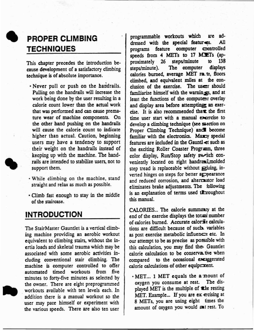
• . PROPER CLIMBINGTECHNIQUES
This chapter precedes the introduction because development of a satisfactory climbingtechnique is of absolute importance.
• Never pull or push on the bandrails.Pulling on the handrails will increase thework being done by the user resulting in acalorie count lower than the actual workthat was performed and can cause premature wear of machine components. Onthe other hand pushing on the handrailswill cause the calorie count to indicatehigher than actual. Caution,' beginningusers may have a tendency to supporttheir weight on the handrails instead ofkeeping up with the machine. The handrails are intended to stabilize users, not tosupport them.
• While climbing on the machine, stand'straight and relax as much as possible.
• Climb fast enough to stay in the middleof the staircase.
INTRODUCTION
The StairMaster Gauntlet is a vertical climbing machine providing an aerobic workoutequivalent to climbing stairs, without the inertia loads arid skeletal trauma which may beassociated with some aerobic activities including conventional stair climbing. Themachine is computer controlled to offerautomated timed workouts from fiveminutes to forty-five minutes as selected bythe owner. There are eight preprogrammedworkouts available with ten levels each. 1naddition there is a manual workout so theuser may pace himself or experiment withthe various speeds. There are also ten user
programmable workouts which are addressed with the special featur~. Allprograms feature computer controlledspeeds from 4 METs to 17 M:Ers (approximately 26 steps/minute to 138step~minute). The computer displayscalories burned, average MET J1Lte, floorsclimbed, and equivalent miles at the conclusion of the exercise. The user shouldfamiliarize himself with the warnin~, and atleast the functions of the computer overlayand display area before attempting an exercise. It is also recommended that. the firsttime user start with a manual ocercise todevelop a climbing technique (see section onProper Climbing Technique) 8D~ becomefamiliar with the electronics. MDJy specialfeatures are included in the Gaunt!<t such asthe exciting Roller Coaster Progr2lIl, threecolor display, Run/Stop safety S'tVitch conveniently located on right handrail,moldedstep tread is replaceable without gluing, inverted hinges on steps for better appearanceand reduced corrosion, and alteraator loadeliminates brake adjustments. The followingis an explanation of terms used tlJroughoutthis manual.
CALORIES... The calorie summary at theend of the exercise displays the toual numberof calories burned. Accurate calode calculations are difficult because of suc~ variablesas post exercise metabolic influence etc. Inour attempt to be as precise as pOSSIble withthis calculation, you may find the Gauntletcalorie calculation to be conservCLtive wbencompared to the occasional e¥Jggeratedcalorie calculations of other equipCllCnt
• MET... 1 MET equals tbe a "Dount ofoxygen you consume at rest. The displayed MET is the multiple of tie restingMET. Etample... If you are ex ercising at8 METs, you are using eight times theamount of oxygen you would at rest. To
§

•be precise, o~e MET equals 3.5 millilitersof oxygen per kilogram {)f body weightper minute.
• AVERAGE MET... -The value obtainedby averagmg the MET rates of all 30 exercise intervals including the warm upand cool down.
• FLOORS... Since step height on theGauntlet is variable, the calculation offloors is based on total work performedand expressed as one floor equaling theamount of work required to climb 16eight inch steps or 10.2 feet.
• MILES... 1 mile is equivalent to 48 floorsclimbed. This calculation is based onstandard work equivalents.
All Gauntlet calculations are directlyequivalent to other StairMaster products.
WARNINGS' .. .
Anyone not accustomed to serious exerciseshould always consult a doctor before usingany exercise device including Gauntlet
Definitely do not allow anyone with a historyof heart trouble or high blood pressure touse Gauntlet except by doctor's prescriptionor consent.
Be cautious of overweight people usingGauntlet for the first time even though theymay have no history of physical difficulty,they may assume it to be far less difficultthan it is, resulting in over exertion.
When using Gauntlet for the first time oneshould remain in the lower speeds until confident before trying the faster speed selections.
Speed and duration of exercise should always be subject to how a person feels, ap-
-5-
parent heart rate or any othel external influence shoul4 never over ride one's ownjudgement when exercising on the Gauntlet
Do not use, adjust, or operate StairMasterexercise equipment without proper instruction by owner authorized personnel.
Persons wearing eyeglasses may have moredifficulty getting used to the machine andshould be given extra attention until familiarwith the Gauntlet.
Do not allow small children .to play unattended near the Gauntlet, especially nearthe moving staircase. Serious injury couldresult from an infant or small child's fascination with the mQving components of the exercise machine.
Never exercise alone if infants or smallchildren are around, it is difficult to observechildren's actions from the exercise position.
Keep hands and feet away from movingparts while machine is in use. Never attempt to repair or adjust machine while inuse.
Do not operate equipment \With loose ordamaged parts. Notify owner or authorizedpersonnel of any problems with equipment.
Although the equipment manufactured byour company has been thoroughly inspectedprior to shipment, proper installation andregular maintenance are required for safety.Maintenance of the exercise equipment isthe responsibility of the equipment ownerand not of StairMaster or its distributors.
StairMaster recommends before initiatingany exercise program, that the user obtain acomplete physical examination from a medical doctor, and enlist the aid of the doctor indevelot>4J8 an exercise program suitable foruser's current health status.
•
.'
••
Failure to comply with these instructionsmay result in personal injury.
BENEFITS
1. MET and other data electronically computed by precise formulas based on the classic work formula of weight and distance. Noother ergometric device 50 accuratelyemploys this physical equation for the purpose of expressing work and associatedphysiological projections. (All formulas confirmed accurate by several independentstudies).
2. When desired, the Gauntlet can producethe quickest rise in heart .rate and vo/2 ofany device, yet its wide range of speeds canaccommodate the infirm or poorly conditioned with equal ease.
3. MET .levels are directly proponional tospeed since work output is weight dependent, MET levels remain the ,same for anyoneregardless of body weight at a given speed.On Gauntlet, MET -levels range from 4-17METs. This feature allows direct comparison, when desired, between individualsof similar demographics but with differentweights, when tested under identical speedconditions, such as athletic teams, militaryrecruits, etc.
4. The Gauntlet never needs calibrationsince the resistance is body weight, not frictional devices which will wear out. Speed iscomputer 'checked 100's of times per second,so calculations are constantly updated andalways aCcurate.
S. Due to the large muscle mass used whenexercising on the Gauntlet, it is possible forsubjects to reach met levels impossible orimpractical to achieve on other equipment.
6. There' are DO inertia or shcxk loads tostress joints, ligaments or muscles as is thecase with other popular forms 0"exercise.
7. There are DO weight limits (lD pauntlet.It bas been operationally tested at weightloads exceeding sao Ibs.
8. No RF interference is generated by themechanics of the Gauntlet beca.lISe there areno electrical motors. The stair case ispowered by body weight and sped controlled by an electromechanical bnuing system.
COMPUTER BASICS
The purpose of the computer console is toprovide automation of the workout and a"friendly" method for obtaini ng necessarydata and displaying workout results. Beforeyour initial exercise on the GallDtlet, it is agood idea to become familiar Vt'ith the computer console and its operation There arethree areas of the console whiell provide theuser interface to the system; the keypadwhich allows data entry and p7()gram selection, the display area which pnvides information to the user either by chartingworkout progress or providing written questions and statements, and lastly the intervaltimer which displays time ren...uining in thecurrent exercise interval.
The computer console bas four operationalmodes:
1. Attract Mode
This is the machine's idle time and is characterized by either the simulated EKG or ascrolling message in the displa::y area. Pressing the reset button from an:)' other modewill return the computer to the attract modeas will allowing the timer to time-out in arest or when answering a question.
•
•
2. Data Entry
This is the phase of the program where theuser must ~put information the computerneeds to control speed and accurately calcu- "late statistics. This mode is entered onlyfrom the attract mode by pressing reset or bystepping on one of the steps. The first question asked is "ENTER WEIGJIT'. Torespond simply press the appropriate numbers on the keypad followed by [ENTER].The range for weight is 1 to 999 pounds.This is used to calculate the calories burnedduring the exercise. The next question is·SELECf PROGRAM". There are nine exercise programs to chose from in the topthree rows of the keypad. The outlines onthe keys correspond to the relative speedlevels of the particular program. H manualis seleeted,the computer has completed thedata entry, if not. then it will prompt with"ENTER LEVEL" and wait for an entry between 1 and 10 with 1 being the easiestworkout.
3. exercise
The exercise portion of the program will always follow the data entry. The exercise willstart with a prompt which rotates through"START EXERCISE", length of workout.and an outline of the workout unless its"Roller Coaster" or ""manual". "Once thesteps start moving the prompt disappearsand the workout is displayed. The programwill be held at this point until the :Run/Stopbutton is pressed. The workout is dividedinto 30 intervals, each one lasting 30 seconds(assuming a 15 minute workout, otherwisethey will represent 1l3Oth of the actualworkout). The flashing column is the current interval and the interval timer showstime remaining in that interval. The speed isrepresented by the height of the column of
·7·
"dots, the bottom dot represents a 4 METspeed and all the dots of a column representa 17 MET speed. The MET' equivalent foreach row of dots is shown on the left handside of the display area. The exercise willallow a" single rest period of two minutes. Ifthe rest period expires or a second rest is attempted the computer will revert to the attract mode and the summary data will belost. The staircase may be slowed to a nearstop at any time by pressing the RunlStopbutton on the right handrail.
4. exercise Summary and GoalComplete
The exercise summary is automatically displayed after the last interval is completed.The summary will display calories burned,average MET rate, floors climbed andequivalent miles. Each new display is accompanied by a ringing sound to alert theuser to the new display. Following the summary is a goal complete message or the jackpot display depending on the owner selectedoption. The computer will return to the attract mode after completing the summaryand goal complete.
OPERATION
Before operating the machine, verify poweris available to the machine by observingeither the simulated EKG or scrolling message in the display area Be sure to read theearlier section on proper climbing techniqueand remember the basics. Relax, stand upstraight and keep up with the machine.
The staircase will continue moving slowlyuntil programing is completed and the .Run/Stop Button on the right handrail ispressed.
E
1
Ps:oep1=fs
tE
I
t.-!
c]
•J
•
To initiate a program, stan by stepping uponto the steps. They will start to fall slowlyunder your weight.. Spend a few ·secondshere getting used to the feel of the machiileand get used to not pushing or pulling on thehandrails.
Observe the display area with the message-ENTER WEIGlIT' with an arrow pointingto the numeric keypad. Enter your weight onthe keypad and press the enter key when it iscorrect. Entry errors may be erased by pressing the clear key.
The display area should now be promptingwith "SELECT PROGRAM" and an arrowpointing towards the top three rows of thekeypad. To familiarize yourself with themachine, selected the manual program.
Upon pressing the Run/Stop button, thesteps move faster than before and you arenow exercising at four METs. AS you become comfortable on the machine try USingthe up and down arrows to adjust your speed(manual is the only program which allowsspeed changes :with .the arrow keys). Thecolumn flashing shows which interval is active and everything to the left of it shows ahistory of the completed intervals. If apreprogrammed workout had been selected,all intervals would be shown and thecolumns to the right of the flashing onewould show the user what to expect. Continue through the entire workout anddevelop a feel for your abilities on themachine. After the last interval is complete,the console will produce a ringing sound anddisplay calories burned for several seconds.This is followed by average MET rate, floorsclimbed, and miles ran, each accompaniedby the same sound and displayed for thesame length of time. Remember youraverage MET rate to use as a guide whenselecting a level for one of thepreprogrammed workouts (subtract fOUT
-8.
from your average MET level aDd use this asa level for one of the preprogrammedworkouts. This is intended to give you astarting point As you become experiencedon the machine, adjust the level to-suit yourabilities).
.1. Scrolling Message
When this option is in effect, the simulatedEKG is replaced by a scrolling messagewhich the owner has entered This messagemay announce club specials, birthday greetings, prizes. etc. The option is automaticallyasserted when a message is entered but thencan be disabled without loosing the message.There is also an optional teletype sound effect which may accompany the message.
Construct your message first on paper usingthe codes for letters, numbers, and symbolsshown in the following chart. All codes aretwo digits. The computer will automaticallyaccept and display the character after thesecond digit is pressed. H you make a mistake, pressing [CLEAR] will remove the lastdigit pressed or remove the characters fromthe display in reverse order if you continueto press [CLEAR]. It is not necessary toleave a space at the beginning or end of yourmessage as the computer does this automatically. The message may contain up to 128characters including spaces.
2. Character Table
A=50 E=54 1=58 M=62 Q=66 U=70
8=51 F=55 J=59 N=63 R=67 V=71
C=52 G=56 K=60 0=64 5=68 W=72
D=53 8=57 L=61 P=65 T=69 X=73
II
IIII
I
•
•
•
Y=74 2=02 7=07 +=22 '=27
Z=75° 30
=03 8=08 $=23 -=28
_=76 4=04 9=09 .=24 -=29
0-=00 5=05 1=20 %=25 #=30
1=01 6=06 -=21 1=26
.=31 :=32
To program the message:
• Computer must be in the attract mode.
• Press 7607 followed by [ENTER]
• Note message appearing on display as it isentered.
• When message is complete, press[ENTER]
• Your message will now begin scrollingand the machine ohas returned to the attract mode.
Sample Message...EXERCISE CAN BEFUN,54,73,54,67,52,58,68,54,76,52,50,63,76,51,54,76,55,70,63[ENTER]
The following codes allow optional controlof the scrolling message.
• press 2123 [ENTER] • This turns message off but retains the message in thecomputers memory. The simulated EKGwill be displayed.
• press 2121 [ENTER] - This turns themessage back on if there is one inmemqry.
• press 40 [ENTER] - turns the teletypesound on.
• press 41 [ENTER] • turns the teletype
sound off.
Just as with the EKG display, pressing[RESET] or moving a step will put themachine into the data entry mode.
3. Changing the Workout nme
The standard workout time is 15 minutes forall programs excluding custom programs.This time is the sum of all 30 interval timesshown by the workout display. Each columnin a standard 15 minute workout representsa 30 second interval. Each interval time isadjusted to lI30th of the total time if a newtime is selected. The workout length may beadjusted by use of this option to any numberof minutes between 5 and 45. The new timeremains in effect for all standard programsuntil it is modified again. We recommendthat this code not be public knowledge andthat programs remain at 15 minutes unlessotherwise needed.
To change the time:
• The computer must be in tbe attractmode.
• Press 1010 [ENTER]
• Enter the desired time (one or twodigits), press [ENTER]
The program will return to the attract modeand the interval timer will reflect the propertime to achieve the new workout time. Thistime setting feature does not affect thelength of any custom programs selected.
4. Custom Programs
Custom programs are user designedworkouts retained in the computersmemory. After entering the code to accesscustom programs, the computer will prompt
- - - -- ----------------------
•
for a program number 1 to 10 (there are tencustom progr~). A workout time isprogrammed along with the 30 MET levels.There are two parts to this section, one oninputting the programs and one section onusing the program. We suggest that theusers mow the codes to access the programsbut not the codes to modify them to preventlampe/ring.
To program a workout:
• Computer must be in the attract mode.
• Press 1650 [ENTER]
• "ENTER PROGRAM" will appear onthe display.
• Enter the number of the program youwish to modify, press [ENTER] .
. If the program number entered has notbeen programmed, you will see a solidrow of dots representing 4 METs for allintervals, otherwise the previous programwill appear and can either be modified orcompletely written over. .
•The flashing dot or column is the one youcan now modify. Use speed arrows tomove column up or down, use [ENTER]to move cursor to the right and [CLEAR]to move cursor to the left.
• When all the columns are correctlyprogrammed, press [RESET] to save "theprogram.
• "ENTER TIME" will appear on the display.
• Enter the desired time between 1 and 45minutes. It should be noted that unlikestandard programs, custom programsallow the time to go down to one minute.
• Press [ENTERJ
Your program has now been savec:i and themachine will return to the attract IDode.
Using custom programs:
• Press 4101 [ENTER]
• Enter the desired program nuz:nber from1 to 10 and press [ENTE}~J
• Continue as with a standarcl exerciseprogram.
Note: You may only select a n~ber thathas been previously programmed Otherwisethe computer will ask you to r-eselect theprogram number.
5. Jackpot Option
At the end of the "exercise s..rrnmary (atworkout completion), there is fa goal complete message. This messase may bereplaced by a Las Vegas style s]ot machine.When the wheels of the slots stop turning,the window will spell out either 'THE END"or "YOU WIN". The odds of "jnning maybe programmed anywhere between 1 in 5 toI in 9,999. The computer will then randomlyselect a winner and display -YOU WIN" instead of the usual 'TIlE END-, After displaying "YOU WIN", the comp"1lter will waitfor the reset button to be pres.sed and thendisplay the current odds. 'Il13s allows theowner to confirm there bas "been no tampering. The odds are modified by the computerto allow a lengthy workout to bve the samewin potential as several short \1lWOrkouts. Theentered od4s are based on th. e standard 15minute workout.
The jackpot option remains in effect untildisabled by entering zero odds. H there isonly one prize, remember to disable the op-
• The compute! automatically returns tothe attract mode. O. No dots•
•
tion when there is a winner. StairMaster andit's distributors assume·no liability stemmingfrom the use of the jackpot option. Use ofthis option may be governed by laws or ordinances in your ar~a.
To turn the jackpot option on, program oddsof 5 or more. To tum off the option andreturn to the standard goal completion message at ·the end of the .summary, programodds to zero.
Enter Odds:
• Computer must be in the attract mode.
• Press 8089 [ENTER]
~ "ENTER ODDS" will appear on thescreen.
• Enter odds between 5 and 9,999 or enterzero to disable the option. Press[ENTER]
When the computer has a winner, the "YOUWIN" display will remain active until[RESET] is pressed. The odds will displayafter [RESET] until it is pressed a secondtime. This is to give the owner a chance toverify ·the win.
Other jackpot codes:
• Press 3121 [ENTER], to display the current odds. [RESEll will return the computer to the attract mode.
• Press 8089 [ENTER], 0 [ENTER] to disable the jackpot option.
·11·
6. Display Check
The display check is intended as a factorytest, but it gives the owner the opportunityto test the display if there is S<lme doubt asto whether all the dots are working.
To perform a display check:
•The computer must be iD the attractmode
• Press the up speed arrow followed by 15[ENTER]
•The display will say "DISPLAY CHECK"for a few seconds, and then turn on all ofthe yellow dots. The other colors may betested as follows:
1. Red dots
2. Green dots
3. Yellow dots
• Press [RESE1] to terminate the displaycheck.
7. Code Summary
• Scrolling Message Codes:
Program message _" 7607
Message on _ _..2121
Message off. - 2123Teletype sound 00. __ 40Teletype sound off __ 41
• Workout Time Code:
Change workout time.......- _ ........1010
tilt
•
•
• Custom Workout Codes:
Programming custom workouts .l650
Using custom workouts 4101
• Jackpot Codes:
Set odds or disable option........•...8089
Display current odds .3121
• Display Check:
Start test.. UP ARROW-15
VOLUME CONTROL
The volume is set at the factory but may beadjusted by the owner. To set the volume,use a sma]] flat blade screw driver to adjustthe volume control through the hole in thebottom of the console. Clockwise rotationincreases the volume (facing the bottom ofthe console).
THEORY OF OPERATION
The Gauntlet is not motor driven. Theelectrical supply to the unit is necessary .onlyfor reliable and consistent operation of theelectronic console. This feature also allowsthe electronics to be viewed when themachine is not being used as opposed tosome other equipment which must be in useto provide an active and viewable display.The body weight of the user provides kineticenergy used for speed control and resistance.This is accomplished by a drive system whichsums the oscillating motion of the steps into
·12·
a continuous rotary motion. This rotary motion is directed to a gearbox which in tumdrives an alternator at sufficient RPM toprovide a smooth, reliable means pf speedcontrol. Excess electrical energy createdduring this process is dissipated in an external electrical resistor in the form of heat. Insummary, the work being performed by theuser (kinetic energy) is converted to electrical energy, which is then converted and dissipated as heat. The size of the electricalload is controlled on the field side of the alternator. This manages the energy at lowcurrent and limits the heat producing components to the load resistor which isdesigned to dissipate heat well in excess ofthe Gauntlet's requirements.
MAINTENANCE
1. Removal Of Side Panels
1. Side panels are attacbed magnetically andare kept in proper alignment by two screwslocated at the top extreme ends of each sidepaneL To remove pane~ remove screw andlift panel at any convenient point until mag.netic contact is broken, hold panel securelyand pull outward.
2. To re-install, align boles in top ends ofpanel with alignment holes before allowingpanel to make magnetic conta~t. Oncepanel is placed over holes, press panel intoplace until magnetic contact is re-establishedaround the entire perimeter of the panel andre-install screws.
2. Bearing and StepshaftReplacement
1. Follow side panel removal procedure andremove side panels.
1. Remove master link.
2. lift idler arm and remove chain. .
•2. Rotate steps until the desired step is 10-' 4. Remove master links and cbain.cated midway between top and bottom axlesunderneath machine. 6. Drive Chain Removal
3. It will be necessary to have a person theopposite side of the machine to hold the nuton the other end of the stepshaft while unscrewing nut.
•
4. Unscrew nut, remove bearing and washer.
5. Using rubber mallet, tap stepshaft throughchain until enough length is exposed on theopposite side to pull the stepsbaft completely free from step.
6. Note: Washers located between the stepand chain on either side will fall free whenstepshaft is removed. Be sure to retain thewasher to re-insert when stepshaft is re-assembled.
7. Remove remaining bearing and washer.
8. To re-assemble follow reverse procedure.
4. Step Removal
1. Follow bearing and stepshaft replacementprocedure to remove stepsbafts.
2. Remove one step at a time, rotating stepsin a clockwise rotation as viewed from theleft side of machine.
3. Repeat above procedure until all stepsare removed.
5. Chain Removal
1. Follow procedure for removing steps, andremove all steps.
2. Loosen screws on bottom axle.
3. Loosen nuts. This will allow chains oneither side to loosen.
7. Sprocket Removal
1. Follow procedure for removing steps andchains and remove both.
2. Loosen shaft set screws in pillow block.
3. Remove pillow block nuts.
4. Sprocket assembly 'can then be removed.
5. Remove pillow block bearings fromsprocket assembly.
8. Speed Reducer Removal
1. Loosen Alternator. Alternator Bracketand bolts put slack in Alternator-Reducerbelt, lift belt off transmission hub,
2. Follow procedure for Drive ChainRemoval and remove drive chain.
3. Remove transmission brace.
4. Remove bolts.
5. Pull Speed Reducer towards you.
6. Remove idler arm and Belt Hub.
7. Remove Roll Pin in sprocket hub andshaft to remove sprocket hub.
8. Remove spring.
-13-
•
•
9. Speed Reducer ·Installatlon
1. Install sprocket assembly onto SpeedReducer shaft. Note orientation. Tightenset saew on key.
2. Install idler arm, spring, and belt bub tothe reducer, put roll pins thru sprocket huband shaft.
3. Install Speed Reducer assembly on mainframe using washers and bolts. Tightenbolts.
4. Assemble transmission brace to mamframe and Speed Reducer.
S. Put Belt on Transmissiop. Tighten Alternator-Reducer Belt. Bolt to Alternator andAlternator Bracket.
10. Sprocket and ChainA~sembly Installation
1. Assemble pillow block bearings to axles.Note: Set screws go to the outside. Do nottighten at this time.
2. Assemble bearing adjusters and sprocketassemblies to main frame studs. Do nottighten at this time. Upper sprocket assembly small sprocket goes to the left side ofmachine.
3. Tighten bearing adjuster set screws ontop sprocket assembly until pillow blockbearings are in the top most position. Then,back out set screw two turns on each bearingadjuster.
4. Using scale, center sprocket assembly between the main frame side rails.
5. Tighten nuts on both upper sprocket assembly pillow block bearings.
.14..
6. Leave lower sprocket assembly loose atthis time.
7. Assemble chain assemblies to sprocketassemblies. Connect chain on one.side withmaster link.
8. It is important at this time to insure thatthe boles for the stepshaft in the chain assemblies are directly in line with each other.To do this, pass a stepshaft thru the holes inthe links of one chain to the holes in thelinks of the chain of the opposite side.Rotate the sprocket assembly until the shaftcomes in contact with the sprocket teeth. Ifthe chains are in alignment, the shaft willcontact the sprocket teeth at exactly thesame moment. If the chains are not in alignment, relocate the chain in the sprocketteeth until alignment occurs.
9. Assemble master link in chain assemblyon opposite side.
10. Tighten bearing adjuster screws on bottom sprocket assembly until chains on eitherside are of equal tension. Note: Tightenuntil chain slack is removed. Do not tightenpast this point.
11. Using scale, center bottom sprocket assembly between sid~ rails, Tighten nuts onbottom pillow block bearings.
12. Tighten all set screws in pillow blockbearings.
11. Stepshaft and BearingAssembly
1. Note: Two people are required for thefollowing procedure.
2. Working from underside of machine,position a step in place and pass a step shaftthru the links of one chain assembly, thru
•
•
•
the hinge of the front pan of step, and onthru the links of the chain on the oppositeside. This should suspend the step in place.
3. Position second step in place..
4. Insert step shaft thru the chain link. Install washer.
5. Connect the two step hinges together andpush the shaft thru the step hinges.
6. When shaft emerges from step hinges onopposite side, install washer before pushingthru the chain links on the opposite chain.
7. Install washers and bearings on both endsof shaft:
8. Assemble nuts on either end of shaft and.tighten. Note: Deformity of threads of oneend of nut. This goes to the outside.
9. Tighten nuts until approximately one andone half threads are visible from end ofshaft.
10. Repeat procedure until all steps are inplace.
11. When all steps are in place there shouldbe approximately 1 1/2 inch chain. deflection.
12. Step Chain Adjustment
1. To tighten chain, loosen the two bearingretainer nuts on each of the two pillow blockbearings located on either side of the unit.Just loosen slightly, do not remove thesenuts.
2. Observe the adjustment set screw whichseats against each of these bearings. A 3/16inch Allen wrench is required to unscrew thescrews.
·15·
3. Tighten these screws an equal amount onboth sides until the correct chain tension isachieved.
4. Re-tighten bearings DUts.
5. To loosen chain follow the above procedure, except loosen set screws 8Il' equalamount on both sides until the required tension release is obtained.
13. Alternator Belt AdJustment/Replacement
14. Machine Alignment
1. It is important for the longevity of thecomponent parts of the machine that it bealigned properly.
2. To visually check the aligmnent of themachine, stand in front of the machine andobseRve The Steps And Chain As TheyRotate Around The Lower Sprocket.
3. Note the shaft on either side of themachine as it initially engages the sprocketteeth. If the machine is misaligned, you willnote that on one side, the step and the chaintend to separate when the shaft engages thetooth. On the other side the step and thechain will tend to come together.
4. To align the machine, loosen the setscrews in the bottom pillow blocks. H thechain and the step tend to separate on theleft side of the machine, move the sprocketassembly shaft slightly to the right. If thechain and the step tend to separate on theright side, move the sprocket assembly to theleft.
5. Movement of sprocket assembly can beaccomplished by tapping the end of thesprocket assembly shaft at the pillow blockbearing.
------~--------------- -
•
e·
e
6. Note: It· may be necessary to move boththe top and bottom sprocket assembly toachieve alignment. Follow the same procedure as above to move upper sprocket assembly.
7. Re-tighten set screws.
8. When the machine is properly alignedyou will. see a very small or no amount ofseparation between steps and chain as thesteps rotate around the bottom sprocket assembly.
LUBRICATION
1. STEPSHAFTS AND HINGES WITHWD40, 1-3 TIMES PER WEEK
2. CHAINS wrrn SAE 30 wr.MOTOROIL, 11lME UGHrLY PER ·MON1E
NOTE: 1. Lubrication frequency will varywith the amount of use.
2. People using the Gauntlet tend toperspire heavily. Perspiration will rust metalrapidly. Therefore, it is important that thelubrication and periodic cleaning requirements of the machine be observed.
3. The stepshafts are most effectively lubricated from a position in front of the unit.Rotate each step into position and attach thered tube to the nozzle of your WD-40 todirect the lubrication only on the hinge area.
NOTE: Do not spray lubricant onto the rubber step, as this will create a potentiallydangerous condition.
4. The inner binge should be lubricated withWD-40 by removing the magnetic sideshields and spraying -each step individuallyfrom inside the unit. The steps can bemoved from the outside by pushing the step
in the opposite direction (clockwise) of itnormal function.
CLEANING PROCEDURE
1. Clean the machine as often IS usage dictates. This may be done with U1f acceptablecleaner and soft cloth. Be especially attentive to cleaning the step hinges as perspiration tend to accumulate here, leading toeventual cosmetic corrosion.

TROUBLESHOOTING
Electrical problems are limited to four areas; the console, the power supply. the cabling.and.the alternator. The purpose of this section is to help identify problems-. We do notrecommend user servicing of the console. Consult panel removal in Mainten arlee sectionfor procedures dealing with the load resistors or the altemator.
1. Electronic
•
•
Symptom:
No display or sound on power up.
-17-
Probable Causes:
EleetricaJ power not ava....ilable at walloutlet. Plug a known goc=»d device intothe outlet (i.e. a lamp, r~d.io etc.). Ifoutlet is not active, use -=t good outletor call an electrician. .
Power supply may be bac::l Use a voltmeter to verify power at coaxial plugon the power supply cesble. Voltageshould read between 12 and 15 volts.If supply is bad, order L. replacementfrom StairMaster.
To verify the cable h.=as not beendamaged, disconnect the gray cable atconsole and measure voL ~ge betweenpins 5 and 4 of the cC=»JlDeetor (thepins are labeled on the:: face of theconnector). It should aIsc::::J indicate between 12 and 15 volts.
The only part left is ta e electronicsconsole. If possible, ~p consolesfrom another machine -to verify theproblem.
•
•
•
Console display has several dots litbut doesn't function.
Machine wi)) not speed control.· Thespeed keeps increasing beyond speedshown.
Machine will not speed control. Runsslow all the time.
MomentariIy unplug the :machine.Upon plugging back.in, if the consoleoperates properly, the symptom wascaused by 8 problem with the 110VAC power from the electric company. If this occurs frequently, itwould be 8 good idea to try themachine on a different electrical circuit.
If the above does Dot resolve thesymptom, the electronics console ismost likely the problem. If possible.swap consoles from another machineto verify the problem.
The load resistor may have malfunctioned. Check for continuity betweenthe +BAT terminal of the alternatorand ground. The resistance will readzero ohms on most meters (0.5 ohmsactual resistance).
The console may also cause thisproblem. Swap consoles if possible. _
The conductor in the gray cable mayDot be continuous. Use an ohm meter-to check for continuity from the fieldterminal of the alternator to pin. 2 ofthe connector (pin nunbers areshown on the face of the connector).
The electronic console has failed,swap consoles if possible.
•
•
•
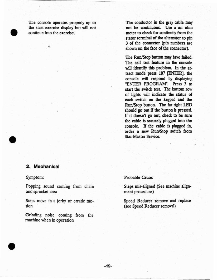
The console operates properly up tothe start exercise display. but will notcontinue into the exercise:
2. Mechanical
Symptom:
Popping sound coming from chainand sprocket area
Steps move in a jerky or erratic motion
Grinding noise coming from themachine when in operation
-19-
The conductor in the gray cable maynot be continuous. Use. an· ohmmeter to check for continuity from thestator terminal of the alternator to pin3 of the connector (pin numbers areshown on the face of the connector).
The Run/Stop button may have failed.The self test feature in the consolewill identify this problem. In the attract mode press 101 [ENTER], theconsole will respond by displaying"ENTER PROGRAM". Press 3 tostart the switch test. The bottom rowof lights will indicate the status ofeach switch on the keypad and theRun/Stop button. The far right LEDshould go out if the button is pressed.H it doesn't go out, check to be surethe cable is securely plugged into theconsole. H the cable is plugged in,.order a new RunlStop switch fromStairMaster Service.
Probable Cause:
Steps mis-aligned (See machine alignment procedure)
Speed Reducer remove and replace(see Speed Reducer removal)
•
•
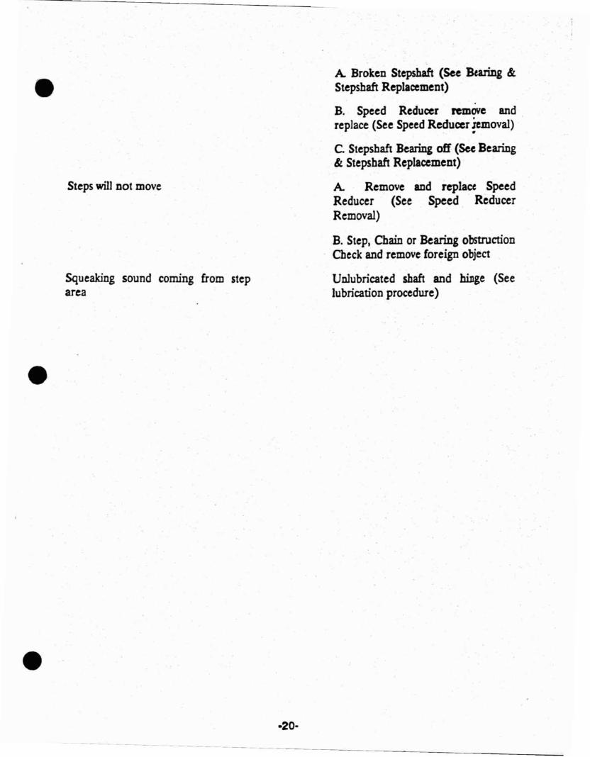
Steps will not move
Squeaking sound coming from steparea
·20·
A Broken Stepshaft (See Bearing &Stepshaft Replacement)
B. Speed Reducer remove andreplace (See Speed Reducer .iemoval)
•
C. Stepshaft Bearing off (See Bearing& Stepshaft Replacement)
A Remove and replace SpeedReducer (See Speed ReducerRemoval)
B. Step, Chain or Bearing obstructionCheck and remove foreign object
Unlubricated shaft and billge (Seelubrication procedure)
~----~ ------_.~----
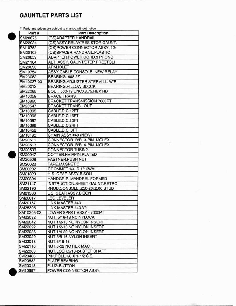
GAUNTLET PARTS LIST
•• Parts and prices are subject to change without notice
•
•
•
Part # Part DescriptionSM20675 CS ADAPTER.HANDRAILSM22934 CS ASSY.RELAY/RESISTOR.GAUNT.SM10753 CS POWER CONNECTOR ASSY. 12/SM20103 CS SPACER.HANDRAIL.PLASTICSM20859 ADAPTER. POWER CORD.3 PRONGSM21164 ALT. ASSY. GAUNT/STEP.PRESTOLISM20693 ARM.IDLERSM10754 ASSY.CABLE CONSOLE. NEW RELAYSM23082 BEARING. 608 2ZSM10037-03 BEARING.ADJUSTER.STEPMILL. W/BSM20012 BEARING.PILLOW BLOCKSM22065 BOLT..500-13 UNCX3.75.HEX HDSM10059 BRACE.TRANS.SM10860 BRACKET TRANSMISSION 7000PTSM20547 BRACKET.TRANS.. OUTSM10395 CABLED.C 12FTSM10396 CABLE.D.C 16FTSM10397 CABLE.D.C 20FTSM10398 CABLE.D.C 24FTSM10452 CABLED.C..8FTSM10195 CHAIN ASSY.#40 (NEW)SM20511 CONNECTOR. RlR. 3-PIN. MOLEXSM20513 CONNECTOR. RlR. 6-PIN. MOLEXSM20509 CONNECTOR.TUBINGSM20047 COITER.HAIRPIN.PLATEDSM20508 FASTNER.PUSH NUTSM20022 TAPEMAGNETICSM20292 GROMMET.1/4 ID.1/16WALLSM21329 H.S. GEAR ASSY.BISONSM20804 HANDGRIP. MANDREL FORMEDSM21147 INSTRUCTION.SHEET GAUNT.RETRO.SM22190 KNOB.CONSOLE..250-20x2.00 STUDSM21330 L.S. GEAR ASSY.BISONSM20017 LEG LEVELERSM20157 L1NK.MASTER.#40SM25305 L1NK.MASTER.#40.V2SM10205-03 LOWER SPRKT ASSY - 7000PTSM22032 NUT. 5/16-18 NC NYLOCKSM22042 NUT.1/2-13 NC NYLON INSERTSM22092 NUT.1/2-13 NC NYLON INSERTSM22036 NUT.1/4-20 NC NYLON INSERTSM22029 NUT.3/8-16.NYLON INSERTSM22018 NUT.5/16-18SM22110 NUT.8-32 NC HEX MACH.SM22063 NUT.LOCK.5/16-24.STEP SHAFTSM20466 PIN.ROLL.1/8 X 1-1/2 S.S.SM20682 PLATEBEARINGSM20018 PLUG.BUITONSM10887 POWER CONNECTOR ASSY.
•
•
•
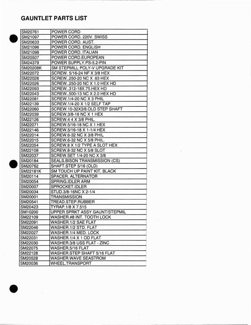
GAUNTLET PARTS LIST
SM20761 POWER CORDSM21097 POWER CORD. 220V. SWISSSM20633 POWER CORD. AUST.SM21096 POWER CORD. ENGLISHSM21 098 POWER CORD. ITALIANSM20507 POWER CORD.EUROPEANSM24379 POWER SUPPLY.PS-5.2-PINSM20208K SM STEPMILL POLV-V UPGRADE KITSM22072 SCREW. 5/16-24 NF X 3/8 HEXSM22028 SCREW..250-20 NC X .63 HEXSM22026 SCREW..250-20 NC X 1.0 HEX HDSM22093 SCREW..312-18X.75.HEX HDSM22043 SCREW..500-13 NC X 2.0 HEX HDSM22081 SCREW.1/4-20 NC X 3 PHILSM22139 SCREW.1/4-20 X 1/2 SELF TAPSM22060 SCREW.1 0-32X3/8.0LD STEP SHAFTSM22039 SCREW.3/8-16 NC X 1 HEXSM22126 SCREW.44 X 3/8 PHIL.SM22071 SCREW.5/16-18 NC X 1 HEXSM22146 SCREW.5/16-18 X 1-1/4 HEXSM22014 SCREW.6-32 NC X 3/8 PHILSM22015 SCREW.6-32 NC X 5/8 PHIL.SM22054 SCREW.8 X 1/2 TYPE A SLOT HEXSM22108 SCREW.8-32 NC X 5/8 SLOTSM22037 SCREW.SET 1/4-20 NC X 3/8SM20184 SEALS.BISON TRANSMISSION (CS)SM20762 SHAFT.STEP 5/16 (OLD)SM22181K SM TOUCH UP PAINT KIT, BLACKSM20114 SPACER. ALTERNATORSM20054 SPRING.lDLER ARMSM20007 SPROCKET.IDLERSM20034 STUD.3/8-16NC X 2-1/4SM20001 TRANSMISSIONSM20541 TREAD.STEP.RUBBERSM20423 TYRAP.1/8 X 7.515SM10200 UPPER SPRKT ASSY GAUNT/STEPMILSM22109 WASHER.#8 INT. TOOTH LOCKSM22091 WASHER.1/2 SAE FLATSM22046 WASHER.1/2 STD. FLATSM22027 WASHER.1/4 MED. LOCKSM22031 WASHER.1/4 X 1 00 FLATSM22030 WASHER.3/8 USS FLAT - ZINC ISM22075 WASHER.5/16 FLATSM22128 WASHER.STEP SHAFT 5/16 FLATSM20528 WASHER.WAVE SEASTROMSM20036 WHEEL.TRANSPORT


![THE GAUNTLET - cLabclab.iat.sfu.ca/pubs/Hawkins-Gauntlet-CHI2015Poster.pdf · [Challenge Description Page] THE GAUNTLET: The Design of a Community Challenge Platform #community #locative-media](https://img.pdfslide.us/doc/110x75/5ed1fb6d5abf7913ed253b8a/the-gauntlet-challenge-description-page-the-gauntlet-the-design-of-a-community.jpg)


![Gauntlet of Ind [TempusFugitives]](https://img.pdfslide.us/doc/110x75/5695d4dc1a28ab9b02a31289/gauntlet-of-ind-tempusfugitives.jpg)