Embed Size (px)
Citation preview

STEPMILL 7000OWNER’S MANUAL
®

Page iii
© 2001 StairMaster Health & Fitness Products, Inc. StairMaster and Stepmill are registered trademarksor trademarks of StairMaster Health & Fitness Products, Inc. in the United States and/or other countries.
All other trademarks are trademarks of their respective companies. StairMaster is a Rutledge Capital company.
P/N 22869 - A
Printed in the United States.© 2001 StairMaster® Health & Fitness Products, Inc.
All rights reserved.
Corporate Headquarters12421 Willows Road N.E., Suite 100
Kirkland, WA 98034
(800) 635-2936(425) 823-1825
Fax (425) 823-9490www.stairmaster.com

Page iv
WARRANTYThis is to certify that the StairMaster® Stepmill® 7000 PT exercise system iswarranted by StairMaster Health & Fitness Products, Inc. to be free of all defects inmaterials and workmanship. This warranty does not apply to any defect caused bynegligence, misuse, accident, alteration, improper maintenance, or an “act of God”.This warranty is non-transferable from the original owner.
If, within three years from the date of purchase, any part of the StairMasterStepmill exercise system should fail to operate properly (except any accessories ), contactour Customer Service Department to report the problem. When calling, please beprepared to provide the customer service representative with the following information:
• Your name, customer number, shipping address, and telephone number• The model and serial number of the inoperable machine• The date(s) of purchase for the inoperable machine(s)• Your billing address
This information will ensure that you are the only one ordering parts under yourwarranty protection. If warranty replacement parts are shipped to you, you may berequired to return the inoperable part. To facilitate this process, the following policy hasbeen established:
• Please call our Customer Service Department to receive a returnmaterials authorization prior to shipment.
• StairMaster Health & Fitness Products, Inc. will incur all freightcharges for warranty parts ordered for a machine that is less than 45days old. The parts will be shipped to you via an overnight courier.*
• You are responsible for freight charges on warranty parts formachines that are more than 45 days old. You will not be responsiblefor the return shipment of the inoperable parts.
• Some inoperable warranty parts must be promptly returned to ourCustomer Service Department. We will pay the shipping cost for theinoperable warranty parts. Detailed instructions are included witheach warranty replacement part.
StairMaster Health & Fitness Products, Inc. neither makes, assumes norauthorizes any representative or other person to make or assume for us, any otherwarranty whatsoever, whether expressed or implied, in connection with the sale, service,or shipment of our products. We reserve the right to make changes and improvements inour products without incurring any obligation to similarly alter products previouslypurchased. In order to maintain your product warranty and to ensure the safe and efficientoperation of your machine, only authorized replacement parts can be used. This warrantyis void if parts other than those provided by StairMaster Health & Fitness Products, Inc.are used.
* Note: Aerosol products cannot be transported via air.

Page v
PREFACEThe StairMaster® Stepmill® 7000 PT exercise system is a safe, functional, andeffective exercise modality for developing aerobic fitness and increasing thestrength of the major muscle groups of the lower body. It is designed for use byindividuals of all ages and fitness levels. Your purchase of this machine is apositive affirmation of your commitment to use the best available methods forenhancing your functional fitness capabilities. In order to derive optimal benefitsfrom your machine, you should read this manual thoroughly and adhere closely tothe instructions.
WHAT IS IN THIS MANUAL?
Following the information on installation and a brief explanation of how theStepmill 7000 PT exercise system works, this manual contains two majorsections. The first section provides an explanation of how the machine should beused to achieve maximum results. The second section offers instructions andadvice on how to properly maintain your machine. The “Appendix” containsadditional information for the owner.
Throughout this Manual, whenever you are required to enter information intothe console, the console keypad keystrokes are enclosed in [ ]. The names of thebuttons and special console operational modes are shown in capital letters. Forexample, your machine is ready for use when the console displays "SELECTWORKOUT." Press the [MANUAL] button to start the MANUAL exerciseprogram.
WHAT IS THE STAIRMASTER STEPMILL 7000 PT EXERCISE SYSTEM?
The StairMaster Stepmill 7000 PT exercise system is a vertical climbingmachine with a rotating staircase which provides an aerobic workout equivalentto climbing stairs, without the impact loads and skeletal trauma common tomost aerobic activities. Regular use of the Stepmill 7000 PT exercise systemstrengthens and conditions the heart and the following lower body musclegroups: gluteals, quadriceps, hamstrings, and calf muscles.

Page vi
CONTENTSSAFETY GUIDELINES ......................................................................................... 1
INSTALLATION INSTRUCTIONS........................................................................ 3
BASIC OPERATING INSTRUCTIONS ................................................................ 6General Guidelines for Safe Operation ........................................................... 6Your First Workout on the StairMaster® Stepmill® 7000 PTExercise System ............................................................................................. 7Basic Instructions for First-Time Users .......................................................... 7Rest periods .................................................................................................... 8
HEART RATE MONITORING ............................................................................ 10Locked/Non-Locked Option ......................................................................... 10Error Messages ............................................................................................ 11
TELEMETRY (POLAR®) HEART RATE............................................................. 12Using the Transmitter Belt ........................................................................... 12Maintaining the Transmitter Belt ................................................................ 13
7000 PT CONSOLE ............................................................................................. 14The Display Window .................................................................................... 14The Numeric Keypad.................................................................................... 15The Entertainment Keypad .......................................................................... 15The Intensity Level Keys .............................................................................. 15The Stop Key ................................................................................................ 15The Workout Statistics ................................................................................ 16The Exercise Program Keypad..................................................................... 17
The Quick Start Option ............................................................................. 17The Manual Program................................................................................ 17The Fat Burner Program ........................................................................... 18The Aerobic Training Program ................................................................. 18The Speed Intervals Program .................................................................. 18The Constant Heart Rate Program .......................................................... 19
The Fitness Test Programs ........................................................................... 20Understanding Submaximal Exercise Testing ............................................ 20Pretest Screening ......................................................................................... 22The StairMaster Submaximal Fit Test ......................................................... 22The Firefighter's Stair Climb Tests .............................................................. 25
Page vii
CONTENTS
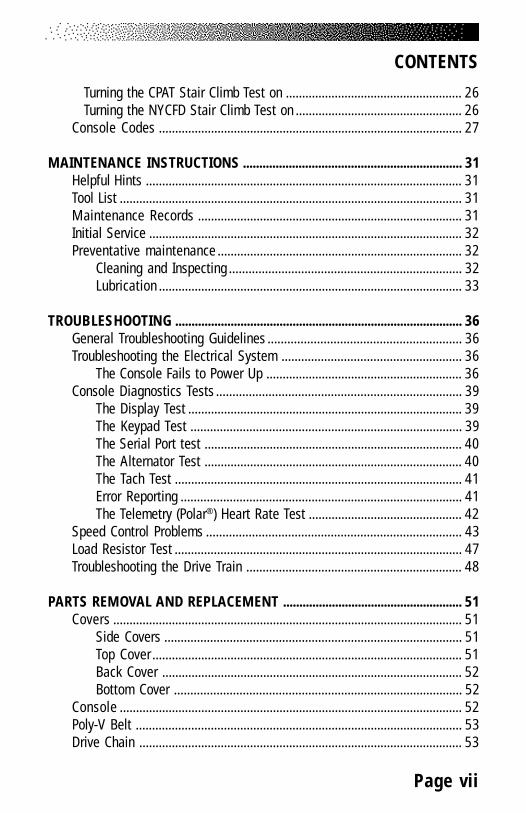
Turning the CPAT Stair Climb Test on ...................................................... 26Turning the NYCFD Stair Climb Test on ................................................... 26
Console Codes ............................................................................................. 27
MAINTENANCE INSTRUCTIONS ................................................................... 31Helpful Hints ................................................................................................. 31Tool List ......................................................................................................... 31Maintenance Records ................................................................................. 31Initial Service ................................................................................................ 32Preventative maintenance ........................................................................... 32
Cleaning and Inspecting ....................................................................... 32Lubrication ............................................................................................. 33
TROUBLESHOOTING ........................................................................................ 36General Troubleshooting Guidelines ........................................................... 36Troubleshooting the Electrical System ....................................................... 36
The Console Fails to Power Up ............................................................ 36Console Diagnostics Tests ........................................................................... 39
The Display Test .................................................................................... 39The Keypad Test ................................................................................... 39The Serial Port test ............................................................................... 40The Alternator Test ............................................................................... 40The Tach Test ........................................................................................ 41Error Reporting ...................................................................................... 41The Telemetry (Polar®) Heart Rate Test ............................................... 42
Speed Control Problems .............................................................................. 43Load Resistor Test ........................................................................................ 47Troubleshooting the Drive Train .................................................................. 48
PARTS REMOVAL AND REPLACEMENT ....................................................... 51Covers ........................................................................................................... 51
Side Covers ........................................................................................... 51Top Cover ............................................................................................... 51Back Cover ............................................................................................ 52Bottom Cover ........................................................................................ 52
Console ......................................................................................................... 52Poly-V Belt .................................................................................................... 53Drive Chain ................................................................................................... 53

Page viii
Step Assembly .............................................................................................. 54Step Chain Assembly ................................................................................... 55Upper (and Lower) Sprocket Assembly ....................................................... 57Cable Assembly ............................................................................................ 59Transmission Assembly ................................................................................ 60Alternator Assembly ..................................................................................... 61Relay/Resistor Assembly ............................................................................. 62
GROUNDING INSTRUCTIONS ......................................................................... 64
FCC COMPLIANCE ............................................................................................. 65
CANADIAN DOC CLASS A COMPLIANCE ..................................................... 65
APPENDICESImportant Phone Numbers ........................................................................... 66Figures 6 - 12 ................................................................................................ 67
LIST OF TABLESTable 1. Dimensions and Specifications for the
StairMaster® 7000 PT Exercise System ................................................ 3Table 2. Fitness Rating Norms ..................................................................... 14Table 3. Recommended Preventive Maintenance Schedule .................... 35
LIST OF ILLUSTRATIONSFigure 1: Correct Exercise Position ................................................................ 9Figure 2: Transmitter Belt ............................................................................. 13Figure 3: The Stepmill 7000 PT Console ..................................................... 14Figure 4: StairMaster Fitness Protocol ........................................................ 24Figure 5: Grounding System......................................................................... 64Figure 6: Side Cover and Handrail Assemblies ........................................... 67Figure 7: Cover Fasteners ............................................................................ 68Figure 8: Step Assembly .............................................................................. 69Figure 9: Step Chain and Sprocket Assemblies ......................................... 70Figure 10: Transmission and Alternator Assemblies .................................. 71Figure 11: Wiring Diagram ........................................................................... 72Figure 12: Relay Board ................................................................................. 73
CONTENTS
Page 1
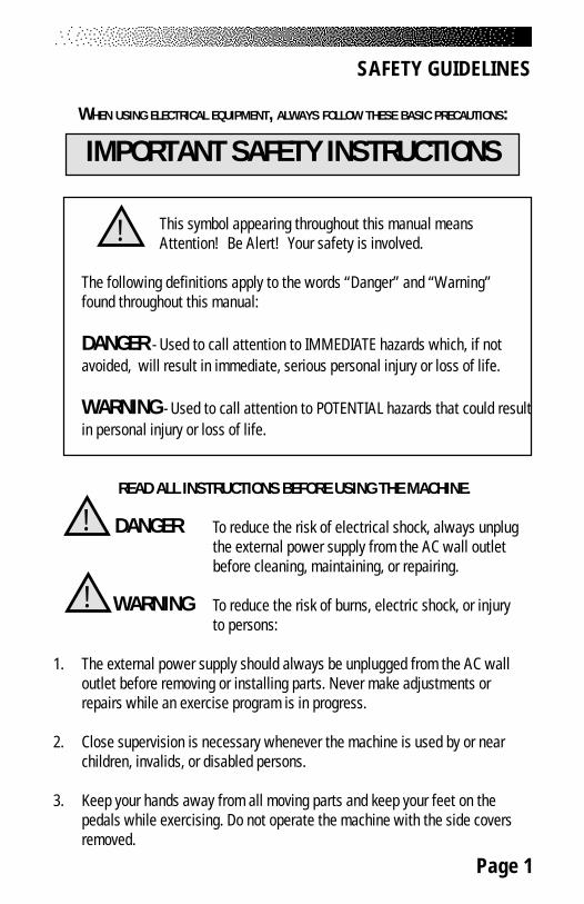
WHEN USING ELECTRICAL EQUIPMENT, ALWAYS FOLLOW THESE BASIC PRECAUTIONS:
IMPORTANT SAFETY INSTRUCTIONS
This symbol appearing throughout this manual meansAttention! Be Alert! Your safety is involved.
The following definitions apply to the words “Danger” and “Warning”found throughout this manual:
DANGER - Used to call attention to IMMEDIATE hazards which, if notavoided, will result in immediate, serious personal injury or loss of life.
WARNING - Used to call attention to POTENTIAL hazards that could resultin personal injury or loss of life.
READ ALL INSTRUCTIONS BEFORE USING THE MACHINE.
To reduce the risk of electrical shock, always unplugthe external power supply from the AC wall outletbefore cleaning, maintaining, or repairing.
To reduce the risk of burns, electric shock, or injuryto persons:
1. The external power supply should always be unplugged from the AC walloutlet before removing or installing parts. Never make adjustments orrepairs while an exercise program is in progress.
2. Close supervision is necessary whenever the machine is used by or nearchildren, invalids, or disabled persons.
3. Keep your hands away from all moving parts and keep your feet on thepedals while exercising. Do not operate the machine with the side coversremoved.
SAFETY GUIDELINES
!
DANGER!
WARNING!
Page 2
4. Use this machine only for its intended use as described in this Manual. Donot use parts, attachments, or accessories other than those provided byStairMaster® Health & Fitness Products, Inc.
5. Do not use the external power supply if it has a damaged cord or plug, or ifit is not working properly, if it has been dropped or damaged, or droppedinto water. Contact our Customer Service Department at 1-800-331-3571 to arrange for the return of damaged parts.
6. Connect the external power supply to a properly grounded AC walloutlet; refer to the “Grounding Instructions” section. Keep all cordsaway from heated surfaces.
7. To disconnect the external power supply, remove the plug from the ACwall outlet.
8. Never drop or insert any object into any opening on the machine.
9. Do not operate where aerosol (spray) products are being used.
10. Always wear insulated gloves when handling batteries.
11. Do not use the machine outdoors.
The safety level given by the design of this equipment can only bemaintained when the equipment is regularly examined for damage and wear. In-operable components shall be replaced immediately or the equipment shall beput out of use until it is repaired. Failure to follow all guidelines may compromisethe effectiveness of the exercise experience, expose yourself (and possibly oth-ers) to injury, and reduce the longevity of the machine. Follow all training instruc-tions listed in the manual and/or on the machine. Physical injury may result fromincorrect or excessive training.
SAVE THESE INSTRUCTIONS
SAFETY GUIDELINES
Page 3
INSTALLATION INSTRUCTIONSBefore leaving the manufacturing facility in Tulsa, Oklahoma, your StairMaster®
Stepmill® 7000 PT exercise system was thoroughly inspected and tested forproper operation. To minimize shipping damage, careful attention was given tomaking your machine ready for shipment.
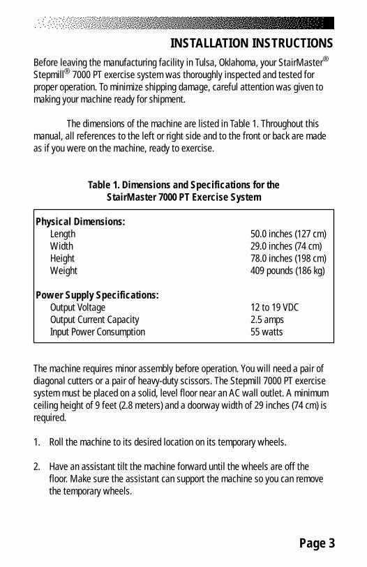
The dimensions of the machine are listed in Table 1. Throughout thismanual, all references to the left or right side and to the front or back are madeas if you were on the machine, ready to exercise.
Table 1. Dimensions and Specifications for theStairMaster 7000 PT Exercise System
Physical Dimensions:Length 50.0 inches (127 cm)Width 29.0 inches (74 cm)Height 78.0 inches (198 cm)Weight 409 pounds (186 kg)
Power Supply Specifications:Output Voltage 12 to 19 VDCOutput Current Capacity 2.5 ampsInput Power Consumption 55 watts
The machine requires minor assembly before operation. You will need a pair ofdiagonal cutters or a pair of heavy-duty scissors. The Stepmill 7000 PT exercisesystem must be placed on a solid, level floor near an AC wall outlet. A minimumceiling height of 9 feet (2.8 meters) and a doorway width of 29 inches (74 cm) isrequired.
1. Roll the machine to its desired location on its temporary wheels.
2. Have an assistant tilt the machine forward until the wheels are off thefloor. Make sure the assistant can support the machine so you can removethe temporary wheels.

Page 4
3. Remove the clevis pin from each wheel (See Drawing Below) and removethe wheels from the frame.
4. Help your assistant lower the machine to the floor. Install and adjust theleg levelers as necessary to level the machine (see Above).
5. If your machine was shipped outside North America, it will need additionalassembly (if this is not the case, skip to step #6).
• Use the fastener removal tool to remove the 8 fasteners on the backpanel.
• Mount both handrails onto the frame as shown in Figure 6.• Push the console cable assembly through the grommet in the frame
and connect it to the main cable assembly (refer to Figure 6).• Install the console mount onto the handrails (refer to Figure 6).• Install the console and connect the console cable.• Reinstall the back panel and go to step #6.
6. Unwrap the power supply assembly from the console and connect the DCpower cable from the power supply to the power connector located on thebottom cover.
7. Place the power supply on the floor near an AC wall outlet. To reduce thehazard of electrical shock, place the power supply in a location away fromthe machine and away from exposure to perspiration. You should notplace your power supply on a carpet because it may overheat.
8. Check to be sure that the input AC power rating marked on the powersupply matches the available power. If it does not, obtain the matchingpower supply from StairMaster® Health & Fitness Products, Inc. beforeproceeding any further.
INSTALLATION INSTRUCTIONS
Cotter Pin2 X 20047 Transport Wheel
2 x 20036
Leg Leveler4 X 20017
Nut4 X 22154
Outside of Machine
Rivnut4 X 21767
Clevis Pin2 X 24439
Page 5
!
INSTALLATION INSTRUCTIONS
WARNING
TO REDUCE THE RISK OF ELECTRICAL SHOCK AND FIRE AND TO PREVENT SEVEREDAMAGE TO THE MACHINE, USE ONLY THE POWER SUPPLY APPROVED FOR USE
WITH THIS EQUIPMENT. IN ADDITION, YOUR MACHINE MUST BEPROPERLY GROUNDED.
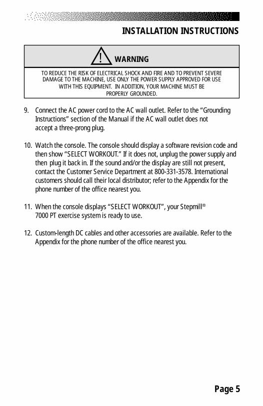
9. Connect the AC power cord to the AC wall outlet. Refer to the “GroundingInstructions” section of the Manual if the AC wall outlet does notaccept a three-prong plug.
10. Watch the console. The console should display a software revision code andthen show “SELECT WORKOUT.” If it does not, unplug the power supply andthen plug it back in. If the sound and/or the display are still not present,contact the Customer Service Department at 800-331-3578. Internationalcustomers should call their local distributor; refer to the Appendix for thephone number of the office nearest you.
11. When the console displays “SELECT WORKOUT”, your Stepmill®
7000 PT exercise system is ready to use.
12. Custom-length DC cables and other accessories are available. Refer to theAppendix for the phone number of the office nearest you.

Page 6
BASIC OPERATING INSTRUCTIONSGENERAL GUIDELINES FOR SAFE OPERATION
WARNING
THESE GUIDELINES ARE DIRECTED TO YOU, AS THE OWNER OF THEMACHINE. YOU SHOULD INSIST THAT ALL USERS FOLLOW THE SAME GUIDELINES.
YOU SHOULD MAKE THIS MANUAL AVAILABLE TO ALL USERS.
1. Obtain a complete physical examination from your medical doctor andenlist a health/fitness professional’s aid in developing an exerciseprogram suitable for your current health status.
2. When working out for the first time, use the MANUAL exercise program atthe lower speeds until you feel comfortable and capable of faster speeds.
3. The speed and duration of your exercise program should always besubject to how you feel. Never permit peer pressure to exceed yourpersonal judgment while exercising.
4. Overweight or severely deconditioned individuals should be particularlycautious when using the machine for the first time. Even though suchindividuals may not have histories of serious physical problems, they mayperceive the exercise to be far less intense than it really is, resulting in thepossibility of overexertion or injury.
5. Although all equipment manufactured by StairMaster Health & FitnessProducts, Inc. has been thoroughly inspected by the manufacturing facilityprior to shipment, proper installation and regular maintenance arerequired to ensure safety. Maintenance is the sole responsibility of theowner.
!

Page 7
YOUR FIRST WORKOUT ON THE STAIRMASTER® STEPMILL® 7000 PTEXERCISE SYSTEM
Basic Instructions for First-Time Users
1. Warm up with light calisthenics and easy stretching exercises for at leastfive minutes before beginning your exercise program.
2. Hold onto the handrails and step up onto the staircase. Stand up straight.The steps will rotate slowly.
3. Select the MANUAL exercise program so you can control the pace of yourfirst workout and get used to the exercise motion.
4. Press [MANUAL] and then [ENTER]. The console will return to the startscreen if you do not press [ENTER] within ten seconds.
5. The console will prompt you to enter your body weight. Enter your weightin pounds (or kilograms if the console is set up for metric units). Correctentry errors by pressing [CLEAR] before you press [ENTER].
6. The console will prompt you to enter the workout time in one-minuteincrements between five and 99 minutes. Press [1], [0], [ENTER] to exercisefor ten minutes.
7. Step up with one foot at a time. Try to stay towards the top of thestaircase. As you become comfortable with exercise motion, press[LEVEL: ∧] and [LEVEL: ∨] to adjust your climbing speed.
BASIC OPERATING INSTRUCTIONS
! WARNING
IF AT ANY TIME DURING YOUR WORKOUT YOU FEEL CHEST PAIN,EXPERIENCE SEVERE MUSCULAR DISCOMFORT, FEEL FAINT, OR ARE SHORT OFBREATH, STOP EXERCISING IMMEDIATELY. IF THE CONDITION PERSISTS, YOU
SHOULD CONSULT YOUR MEDICAL DOCTOR IMMEDIATELY.

Page 8
BASIC OPERATING INSTRUCTIONS8. Relax as much as possible while exercising and maintain an erect posture.
Use the handrails for balance. Don’t lock your elbows or lean on theconsole. Supporting your weight will reduce the exercise intensity and theconsole will overestimate the number of calories burned.
9. Select a speed (or intensity level) that allows you to step towards the topof the staircase. Faster is not always better. Exercise at a level that isconsistent with your fitness level.
Rest Periods
10. You can stop and rest as many times as necessary for up to oneminute for each rest period during all programs. To stop, either press[STOP] or step off the machine. The console returns to the start screen ifyou rest longer than the allotted rest period. Follow the onscreenprompt to continue your work out after a rest period.
Cool Down
11. When you are finished with your workout, the machine will slowdown and the message “GOAL ATTAINED” will be displayed. You cancool down on the machine by continuing to step. The console timerwill continue to count up from the selected time, and the intensitylevel will default to level 3. If there is a time limit set on the console,the timer will last only until the maximum time has been met. Forexample, if the time limit was set for 30 minutes and you worked outfor 25 minutes, the cool down period would last for 5 minutes, or untilyou stepped off the machine.
12. You can also cool down by getting off the machine walking orstretching for at least five minutes.
Page 9
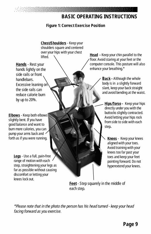
Head - Keep your chin parallel to thefloor. Avoid staring at your feet or thecomputer console. This posture will alsoenhance your breathing.*
Back - Although the wholebody is in a slightly forwardslant, keep your back straightand avoid bending at the waist.
Hips/Torso - Keep your hipsdirectly under you with thebuttocks slightly contracted.Avoid letting your hips rockfrom side to side with eachstep.
Legs - Use a full, pain-freerange of motion with eachstep, straightening your legs asfar as possible without causingdiscomfort or letting yourknees lock out.
Feet - Step squarely in the middle ofeach step.
Chest/Shoulders - Keep yourshoulders square and centeredover your hips with your chestlifted.
Hands - Rest yourhands lightly on theside rails or fronthandlebars.Excessive leaning onthe side rails canreduce calorie burnby up to 20%.
Elbows - Keep both elbowsslightly bent. If you havegood balance and want toburn more calories, you canpump your arms back andforth as if you were running. Knees - Keep your knees
aligned with your toes.Avoid training with yourknees too far past yourtoes and keep your feetpointing forward. Do nothyperextend your knees.
*Please note that in the photo the person has his head turned - keep your headfacing forward as you exercise.
Figure 1: Correct Exercise Position
BASIC OPERATING INSTRUCTIONS

Page 10
HEART RATE MONITORING
HEART RATE INPUT
The 7000 PT console uses telemetry (e.g., Polar®) heart rate signal detection.Ensure that your console is set up for telemetry signal detection only. There is ashort “lock out” period at the beginning of each workout session during whichthe console first detects a signal and then validates the signal type.
• Telemetry heart rate - after the initial belt signal is detected, theconsole will enter a validation phase in which four good heartbeat signals within four seconds are required beforelocking on telemetry heart rate signals for the duration of theworkout session. During the validation phase the console will notrecognize contact heart rate signals.
Locked/Non-locked Option
When the “not locked” option is selected the heart rate source signal is not fixedduring the exercise (if the signal is lost either input will be valid). If the “locked”option is selected then the heart rate source signal is locked on the first detectedsignal during the workout. To set a heart rate signal input, or to turn off the heartrate option all together, perform the following steps:
1. On the console keypad, press [LEVEL: ∧] , [3], [2]. At this point thescreen will display “HR INPUTS.” Press [ENTER] to select thisoption.
2. There are 4 options to handle heart rate input signals. Only 2 ofthose options are appropriate for the 7000 PT; "Both HR Off", and"Telemetry Only." Press the [SELECT] key to scroll past the otheroptions until you find either "Both HR Off" or "Telemetry Only."Press the [ENTER] key to select the desired option.
Page 11
HEART RATE MONITORING
“TELEMETRY ONLY“ - locks out contact heart rate signalsand will only detect telemetry signals. Set your console to thisdefault.“BOTH HR OFF“ - turns off the ability to detect any signal at all.Used in rare situations where there is excessive interference withthe heart rate signals. This option turns off disables theConstant HR program and the Fitness Test program.
Error Messages
Text line messages are only seen in the Constant Heart Rate and Fitness Testprograms due to the design of the program that necessitates a valid heart ratesignal at all times during the program.
“CHECK HR BELT” - The heart rate signal has been missing forthe last 30 seconds in telemetry signal detection.“HR BELT NEEDED” - No telemetry belt signal been sensedduring the initial setup time.“HR MODE DISABLED” - No heart rate signal is allowed due tothe set up option that was chosen. Heart rate monitoring is notpossible.
Page 12
TELEMETRY HEART RATE
TELEMETRY HEART RATE
The StairMaster® Stepmill® 7000 PT features telemetry (Polar®) heart rate moni-toring. The system consists of the receiver, located on the stepper, and a trans-mitter belt (purchased separately) worn across your chest. The monitoring func-tion is activated as soon as you strap on the chest belt and step within range ofthe receiver in the machine. Two electrodes on the underside of the chest beltsense the heart rate signal and send it to the receiver. The heart symbol on theconsole pulses to indicate that the console is receiving a valid signal. A micropro-cessor in the console calculates the heart rate and displays it, in beats perminute, on the console.
Using the Transmitter Belt
Before you put the transmitter belt on, wet the two electrode patches(the grooved rectangles on the reverse side of the belt). Secure the transmitterbelt as high under the pectoral muscles (chest) as is comfortable. The transmitterbelt should fit snugly and comfortably, and allow normal breathing. When theconsole detects a heart rate signal, heart rate is shown in the display automati-cally. Your heart rate in beats per minute and a pulsing heart icon are displayedon the console.
After the initial belt signal is detected, the console will enter a valida-tion phase in which four good heart beat signals lasting four seconds each arerequired before locking on telemetry heart rate signals for the duration of theworkout session. During the validation phase the console will not recognizecontact heart rate signals. If you do not see a heart rate on the console, try oneof the following:
• Move closer to the console.
PACEMAKER USERS SHOULD NOT USE THE POLARTRANSMITTER BEFORE CONSULTING THEIR DOCTOR.
! WARNING

Page 13
TELEMETRY HEART RATE
• Tighten the elastic part of the chest belt.• Adjust the belt higher or lower on your chest.• Remoisten the electrodes.• Test your chest strap with a machine that you know is working, or
with a heart rate watch that you know is working.• If possible, replace or exchange your console with a console
(from the same type of machine) that you know is working andretest the machine.
• Visually check that the heart rate receiver is positioned correctlyin the neck cover. The heart rate receiver jack should point down.Ensure that the heart rate receiver is connected to the console,and that the connection is not loose. If possible, swap the heartrate receiver with one from another machine.
Figure 2: Transmitter Belt
Maintaining the Transmitter Belt
Clean the chest belt regularly with mild soap and water, then dry thoroughly -residual sweat and moisture keep the transmitter active and drain the battery inthe transmitter. Do not use abrasives or chemicals such as steel wool or alcoholfor cleaning, as they can damage the electrodes permanently. You can orderreplacement belts from StairMaster, Polar Electro, Inc., or your local fitness store:
StairMaster 800-331-3578 P/N 64000Polar Electro, Inc. 800-227-1314

Page 14
The StairMaster® Stepmill® 7000 PT exercise system console is divided intoseven sections: the display window, the workout options, the numeric keypad,the entertainment keypad, the workout statistics, the stop key, and the intensitylevel keys (see Figure 3).
Figure 3: The Stepmill 7000 PT Console
THE DISPLAY WINDOW
• Time - The selected workout time is displayed in theupper left section of the display window. Once the timeis entered, the timer will count down, in minutes andseconds, until the workout is finished or stopped. If [0]is entered in the MANUAL or CONSTANT HEART RATEprogram, the timer will count up.
• Calories - The real-time amount of calories burned is continually updated anddisplayed in the upper right section of the display window.• Interval Timer - The interval timer is displayed below the Time. The intervaltimer counts down time left within each interval.• Heart Rate - Current heart rate is displayed below the Calories, next to theheart icon.• Workout Option Profile - A profile of the selected exercise program appearsin the lower section of the display window during a workout. The taller the col-umn, the higher the intensity (watts) for that interval. The flashing column showsyour current interval. The flashing column moves from left to right across the dis-play as you complete each interval.
Display Window
EntertainmentKeypad
NumericKeypadWorkout Options
Workout Statistics Stop Intensity Level
7000 PT CONSOLE

Page 15
THE NUMERIC KEYPAD
The numeric keypad is located on the right side of the console.Before the exercise program begins, the numbers are used toenter data in response to the console prompts.• Enter - Confirms workout selections and stores the informa-tion used by the console to calculate workout statistics.• Clear - Erases information from the console memory ifpressed before [ENTER].
THE ENTERTAINMENT KEYPAD
The FreeClimber comes equipped to facilitate the use of com-mercial entertainment systems. Using any of these keys willsend an output signal through the Communication Specifica-tion for Fitness Equipment (C.S.A.F.E.) port to a connectedC.S.A.F.E. or compatible system. If a system is not connected,pressing these keys will have no effect.
• Volume Up/Down - Increases or decreases the volume level of the audiosource.• Mute - Removes the audio sound from the headphones.• Channel Up/Down - Changes the channel of the commercial entertainmentsystem.
THE INTENSITY LEVEL KEYS
The exercise intensity level may be changed at any time duringa workout. Pressing the [ ∨ ] key decreases the intensity andpressing the [ ∧ ] key increases the intensity.
STOP KEY
Press the [STOP] key any time you want to pause the exerciseprogram for up to one minute. Press [STOP] a second time, or[1], and The console will return to the "SELECT WORKOUT"
Prompt.
7000 PT CONSOLE
Page 16
THE WORKOUT STATISTICS
During the exercise program, the Stats keys are used to track workout statisticswhich are then shown in the display window. Pressing the [SELECT] key turns offthe scanning feature and shows the statistic of choice in the display window.Pressing the [SCAN] key will prompt the console to cycle through the followingstatistics:
• Distance - Provides a cumulative total of the equivalent distance (in miles orkilometers), you would have traveled while riding a bicycle outdoors at the samerelative intensity.• Calories/Hour - Provides a running total of the number of calories burned dur-ing a workout.• Rate - Displays the current steps per minute.• Floors - Displays the equivalent number of floors climbed with an 8-inch step.There are 16 steps per floor, and 48 floors per mile.• Level - Shows the current intensity level between 1 (the easiest) and 20 (thehardest).• Watts - Displays the exercise intensity in watts (746 watts = 1 horsepower).• METs - Gives you the relative energy cost of exercise. MET stands for mul-tiples of the resting metabolic rate. While you are sitting quietly, your body con-sumes oxygen at the rate of about 3.5 milliliters per kilogram of body mass perminute. When you exercise, your body needs more oxygen in order to function.For example, exercising at 10 METs requires ten times the resting rate of oxygenconsumption, or about 35 milliliters per kilogram per minute. During a workout,this key shows the current MET level. During the workout summary, the averageMET level is displayed.• Target Heart Rate - Available only during the Constant Heart Rate program.Shows the selected target heart rate.
At the completion of a workout, the statistic averages are calculatedbased on the accumulation of data during the workout program, and not includingthe cool down period.
7000 PT CONSOLE
Page 17
THE EXERCISE PROGRAM KEYPAD
The exercise keypad is located below the display and to the left of the functionkeypad. While the console is in the “SELECT WORKOUT” mode, press one of theexercise program keys to preview the desired workout. There are sixworkout programs with the following standard defaults (pressing [ENTER] with-out inputting data first will prompt the console to enter these values):
• Weight - 175 lbs.• Intensity Level - 3• Workout Time - The default time in the programmed workouts
and Quick Start is 20 minutes. The Manual and Constant HeartRate programs do not have a specified default time. In theseprograms, the console timer will count up to the maximum time of99 minutes, and then return to 0.
• Age (Constant Heart Rate program only) - 40 years
Once you have selected a program, the prompts are:
• “ENTER BODY WEIGHT” - type in your body weight inpounds (or kilograms if your console is set to metric units).
• “ENTER LEVEL 1 - 20” - select your intensity level withlevel 1 being the easiest and level 20 the hardest.
• “ENTER TIME 5 - 99” - select the workout duration in oneminute increments from 5 to 99. Press 0 in the MANUAL andCONSTANT HEART RATE program to workout for an unspecifiedamount of time.
The Quick Start Program
Provides an immediate start, without having to enter any user information. Thisprogram uses the standard default settings for derivation of calories burned.
The Manual Program
After pressing the [MANUAL] key, enter user and workout information. Beginexercising at the selected level. If desired, adjust the workout manually byusing the intensity level arrow keys. The profile in the display window isdivided into 15 equal intervals within the workout time. The profile is based
7000 PT CONSOLE

Page 18
on the selected intensity level, with 2 levels equating to one vertical bar.
The Fat Burner Program
The Fat Burner program is a 60-interval workout designed for people juststarting a weight control program. The relative intensity level is indicated on theprofile and any changes in the intensity level will continue for the remainder ofthe program.
The Aerobic Training Program
The Aerobic Training program is a 60-interval workout designed to increaseaerobic capacity. The relative intensity level is indicated on the profile and anychanges in the intensity level will not change the look of the remaining profile.
The Speed Intervals Program
The Speed Intervals program is a workout with 8-rest intervals and 7-exerciseintervals that alternate speed/intensity level changes. You can change the RESTinterval speed/level and the EXERCISE interval speed/level independently, usingthe level keys. For example, if you decrease the intensity level during a rest in-terval then subsequent rest intervals will be the same. However, the EXERCISEinterval remains at the same intensity level you started with. To change theintensity level of the EXERCISE interval, you must change the intensity level
7000 PT CONSOLE

Page 19
during an EXERCISE interval. The intensity level shown during an EXERCISE inter-val is indicative of your current speed. However, the current speed during a RESTinterval is equal to a scaled percentage of the displayed intensity level. Note thatthe program profile does not change at any time during the workout session.
The Constant Heart Rate Program
The Constant Heart Rate program maintains a chosen target heart rate byautomatically varying the climbing speed during each workout. The default targetheart rate is equal to 70% of your maximum heart rate which is calculated by thefollowing equation: 220 - (Age) x .70. Choose a different target heart rate (be-tween 80 and 180 beats per minute) at any time during the workout by using thenumeric keypad to enter the new target heart rate, followed by the [ENTER] key.The following messages may be shown during a workout:
• “CHECK HR BELT” - The heart rate signal has been missing forthe last 30 seconds in telemetry signal detection.
• “HR BELT NEEDED” - No telemetry belt signal has been sensedduring the initial setup time.
• “HOLD HR SENSORS” - In contact heart rate signal situationsthis message will come every 30 seconds to prompt the user tohold the sensors.
• “HR MODE DISABLED” - No heart rate signal is allowed due tothe set up option that was chosen. Heart rate monitoring is notpossible.
Rest Interval Exercise Interval
7000 PT CONSOLE

Page 20
The Fitness Test Programs
Understanding Submaximal Exercise Testing
Before using the StairMaster FreeClimber for submaximal exercise testing, itshould be noted that all submaximal fitness tests make several assumptions:
• That a steady-state heart rate is obtained for each exerciseworkload.
• That a linear relationship exists between heart rate, oxygen uptake and workload.
• That the maximal heart rate for a given age is uniform.• That the mechanical efficiency of the physical activity performed
(i.e., oxygen uptake at a given workload) is the same for everyone.
It should be kept in mind that any one or all of the above mentioned as-sumptions may not be met during a submaximal exercise test. If for anyreason one of the assumptions is not met, then errors in predicting VO2 max willoccur.
Unfortunately, it is often quite difficult to meet all of the requirementsfor the four listed assumptions. For example, exercising at a given workload foronly a few minutes can involve an insufficient amount of time for many individu-als to achieve a true steady-state. To ensure that a steady-state has beenachieved, the heart rate should be measured after two minutes of exercise at agiven workload and again after the third minute of exercise at that workload.These two heart rates should then be compared. If a difference of more than fivebeats per minute between the two is found, the subject should continue to exer-cise at one-minute intervals at the same workload until two successive heartrates differ by less than five beats per minute.
It is also important that the submaximal heart rates obtained bebetween 115 and 150 beats per minute, because it is within this heart rate rangethat a linear relationship tends to exist between heart rate and oxygen uptake orworkload for most adults. When the heart rate is less than 115, many externalfactors (e.g., talking, laughing, apprehension, etc.) can greatly influence heartrate. Once the heart rate reaches a level between 115 and
7000 PT CONSOLE

Page 21
150, external factors no longer influence heart rate, and a linear relationship ex-ists. As the heart rate rises above 150, the heart rate-oxygen uptake relationshipbecomes curvilinear.
The third assumption involves maximal heart rate. Maximal heart rate isthe greatest heart rate that can be measured when an individual is exercising tothe point of volitional fatigue (i.e., exhaustion) during a graded exercise test. Sev-eral equations have been developed to estimate the average maximal heart ratefor humans:
• Maximal heart rate = 220 minus age (low estimate)• Maximal heart rate = 210 minus [0.5 x age] (high estimate)• Maximal heart rate = 226 minus age (estimate for older
individuals)
Maximal heart rate can, however, vary greatly among differentindividuals of the same age. One standard deviation is + 12 bpm, which meansthat two-thirds of the population varies an average of plus or minus 12 heartbeats from the average given by a prediction equation. If an individual’s age-pre-dicted maximal heart rate is higher than that person’s true maximal heart rate,then his/her estimated VO2 max will be an overestimation of the correct or actualvalue.
The final assumption addresses the issue of mechanical efficiency. Be-cause oxygen uptake at any given work rate can vary by approximately 15% be-tween different individuals, individuals vary in the amount of oxygen they requireto perform a certain exercise workload. Some individuals are moreefficient at performing a given task than others. As a result, the averageoxygen consumption associated with a given workload may vary significantlyfrom one person to another. Thus, VO2 max predicted by submaximal exercise teststends to be overestimated for those who are mechanically efficient and underes-timated for those who are inefficient.
The point to remember is that submaximal exercise testing, though notas precise as maximal exercise testing, is not without advantages. Forexample, the results of such testing can provide a fairly accurate reflection of anindividual’s fitness status without the cost, risk, effort (on the part of the subject)and time involved in max testing. If an individual is given repeated
7000 PT CONSOLE

Page 22
submaximal exercise tests and that person’s heart rate response to a fixedworkload is found to decrease over time, it is reasonably safe to conclude thatthe individual has made improvements in aerobic (cardiorespiratory) fitness, irre-spective of the accuracy of the VO2 max prediction.
Pretest Screening
Prior to any exercise test (maximal or submaximal), participants should completea brief health/medical questionnaire, have their resting blood pressure and heartrate measured, and provide an informed consent form. The Physical ActivityReadiness Questionnaire (PAR-Q) is an example of a valid health/medicalquestionnaire for screening individuals prior to submaximal exercise testing.Canadian health and fitness practitioners have extensively (and quite success-fully) used the PAR-Q to determine whether individuals should be given anexercise test. A “yes” answer to any of the seven questions on the PAR-Q woulddisqualify a participant from taking part in an exercise test until appropriatemedical clearance was obtained.
PHYSICAL ACTIVITY READINESS QUESTIONNAIRE (PAR-Q)
1. Has your doctor ever said you have a heart condition and recommendedonly medically supervised physical activity?
2. Do you have chest pain brought on by physical activity?3. Have you developed chest pain within the past month?4. Do you tend to lose consciousness or fall over as a result of dizziness?5. Do you have a bone or joint problem that could be aggravated by the
proposed physical activity?6. Has a doctor ever recommended medication for your blood pressure or a
heart condition?7. Are you aware, through your own experience or a doctor’s advice, of any
other physical reason against your exercising without medical supervi-sion?
The StairMaster Submaximal Fit Test
The StairMaster branching protocol is a series of 3-minute stages ofcontinuous exercise at increasing intensity. The first stage is a warm-up at ap-proximately 4 METs. The intensity of the remaining stages is based on the heartrate response to the warm-up. The test is designed to raise the steady
7000 PT CONSOLE

Page 23
state heart rate of the subject to 110 to 150 beats/min for two consecutivestages. It is important to remember that two consecutive heart rate measure-ments must be obtained in the 110 to 150 beats/min range to predict VO2max.The test typically lasts from 9 to 15 minutes.
In the StairMaster protocol, each work rate is performed for 3minutes, with heart rates recorded during the final 4 seconds of the second andthird minutes of each stage. If the heart rates are within 5 beats/min, then theheart rate during the last minute is plotted against the work rate, and the pro-gram advances to the next 3-minute stage. The program continues for two to fourstages until two steady state heart rates between 110 to 150 beats/min are ob-tained in two consecutive stages. The line generated from the plotted points isthen extended to the age-predicted maximal heart rate. A corresponding maximalwork rate and VO2max can then be calculated.
At the end of the 3rd minute of each stage, if the heart rates at the endof the 2nd and 3rd minute are not within 5 beats/min of each other, then that workrate is maintained for an additional minute. At the end of the 4th minute, theheart rate is compared to the heart rate at the end of the 3rd minute. If the heartrates are within 5 beats/min, then the heart rate during the 4th minute is plottedagainst the work rate. If the heart rate at the end of the 3rd and 4th minute arenot within 5 beats/min, then the work rate is maintained for one more additionalminute. If the heart rate at the end of the 4th and 5th minutes are within 5 beats/min, then the heart rate at the end of the 5th minute is plotted against the workrate. If the heart rate at the end of the 4th and 5th minutes are not within 5 beats/min, then the test failed.
Once two consecutive heart rate measurements are obtained in the 110to 150 beats/min range, then the test ends successfully and the results are dis-played. Estimate maximum aerobic capacity is shown in ml/kg/min and METs.Next, the results are compared to normative values for others of the same agerange and gender (see Table 2). Results are stored in the console until the nextperson starts an exercise program. Press [STATS SCAN] to review the results inaddition to being displayed at the end of the test.
7000 PT CONSOLE

Page 24
Figure 4: StairMaster® Fitness Protocol
First Work Level4 METs
If 100 <= HR <= 120If HR < 100 If HR > 120
Second Work Level7 METs
Second Work Level6 METs
Second Work Level5 METs
Third Work Level9 METs
Fourth Work Level11 METs
Third Work Level8 METs
Fourth Work Level10 METs
FIT TEST PROTOCOLStairMaster CV Products
Test Complete- Display Results -
If HRs >115
If HRs >115If HRs >115
Y
YY
Test fails if 2 stages ofat least 115 bpm are not
obtained
7000 PT CONSOLE

Page 25
Table 2. Fitness Rating Norms (VO2max)
MEN
Age High Good Average Fair Low 20 – 29 >51 51 – 47 47 – 43 42 – 40 <39 30 – 39 >50 50 – 45 45 – 41 41 – 37 <37 40 – 49 >48 48 – 42 42 – 38 38 – 35 <35 50 – 59 >45 45 – 39 38 – 35 35 – 32 <32 60+ >43 42 – 35 35 – 32 32 – 29 <29
WOMEN
Age High Good Average Fair Low 20 – 29 >44 44 – 38 38 – 35 35 – 32 <32 30 – 39 >41 41 – 37 37 – 34 34 – 31 <30 40 – 49 >40 39 – 34 34 – 31 31 – 28 <28 50 – 59 >35 35 – 31 31 – 28 28 – 26 <25 60+ >35 35 – 39 29 – 26 26 – 24 <24
The Firefighter’s Stair Climb Tests
The StairMaster StepMill is routinely used to assess the aerobic fitnesslevels of fire fighters in full protective gear carrying heavy equipment. TheCandidate’s Physical Ability Test (CPAT), approved by the InternationalAssociation of Fire Fighters (IAFF) and reviewed by the U.S. Justice Department,requires each candidate to step on the StepMill at a predetermined steppingpace for a specific period of time. There are two fire fighter specific Stair ClimbTest programs. The first test is the CPAT Stair Climb Test. The second test is amodified version of the CPAT test that is used by the New York City Fire Depart-ment (NYCFD).
• CPAT Stair Climb Test – (Fit Test #2) The first phase is a warm-upinterval at intensity of 56 steps/min and lasts twenty-seconds. Atthe end of the first interval the time counter will reset to zero.The second phase continues through nine twenty-second
7000 PT CONSOLE

Page 26
intervals at intensity of 68 steps/min. The CPAT Stair Climb Testhas a total of ten intervals and lasts for three minutes, twentyseconds (including warm-up).
Turning on the CPAT Stair Climb Test
1. Press [∧ ], [9], [1], [ENTER], on the console keypad. Make sure topress in the middle of each key and be aware that the corre-sponding numbers will not show in the console display.
2. The console will prompt you to “BEGIN FIT TEST.” The testcan be stopped at any time by pressing [STOP].
• NYCFD Stair Climb Test – (Fit Test #3) The first phase is a warm-up interval at intensity of 56 steps/min and lasts sixty-seconds,followed by a sixty-second rest period (no stepping). At the endof the rest period the time counter will reset to zero. The secondphase is at intensity of 68 steps/min and lasts for five minutes,twelve seconds.
Turning on the NYCFD Stair Climb Test
1. Press [∧ ], [9], [2], [ENTER], on the console keypad. Make sure topress in the middle of each key and be aware that the corre-sponding numbers will not show in the console display.
2. The console will prompt you to “BEGIN FIT TEST.” The testcan be stopped at any time by pressing [STOP].
7000 PT CONSOLE
Page 27
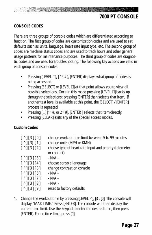
CONSOLE CODES
There are three groups of console codes which are differentiated according tofunction. The first group of codes are customization codes and are used to setdefaults such as units, language, heart rate input type, etc. The second group ofcodes are machine status codes and are used to track hours and other generalusage patterns for maintenance purposes. The third group of codes are diagnos-tic codes and are used for troubleshooting. The following key actions are valid ineach group of console codes:
• Pressing [LEVEL ∧ ], [ 1st # ], [ENTER] displays what group of codes isbeing accessed.
• Pressing [SELECT] or [LEVEL ∧ ] at that point allows you to view allpossible selections. Once in this mode pressing [LEVEL ∨ ] backs upthrough the selections; pressing [ENTER] then selects that item. Ifanother test level is available at this point, the [SELECT] / [ENTER]process is repeated.
• Pressing [∧ ] [1st #, or 2nd #], [ENTER ] selects that item directly.• Pressing [CLEAR] exits any of the special access modes.
Custom Codes
[ ^ ] [ 3 ] [ 0 ] change workout time limit between 5 to 99 minutes[ ^ ] [ 3] [ 1 ] change units (MPH or KMH)[ ^ ] [ 3 ] [ 2 ] choose type of heart rate input and priority (telemetry
or contact)[ ^ ] [ 3 ] [ 3 ] - N/A -[ ^ ] [ 3 ] [ 4 ] choose console language[ ^ ] [ 3 ] [ 5 ] change contrast on console[ ^ ] [ 3 ] [ 6 ] - N/A -[ ^ ] [ 3 ] [ 7 ] - N/A -[ ^ ] [ 3 ] [ 8 ] - N/A -[ ^ ] [ 3 ] [ 9 ] reset to factory defaults
1. Change the workout time by pressing [LEVEL: ^], [3 , [0]. The console willdisplay “MAX TIME.” Press [ENTER]. The console will then display thecurrent time limit. Use the keypad to enter the desired time, then press[ENTER]. For no time limit, press [0].
7000 PT CONSOLE

Page 28
2. Change the units to either Metric or USA units by pressing [LEVEL: ^], [3],[1], [ENTER]. The console will display the current units - either “USAUNITS” or “METRIC UNITS.” Use the [SELECT] key to change option, andthen press [ENTER].
3. Choose the desired heart rate input preference by pressing [LEVEL: ^],[3], [2]. The console will then display “HR INPUTS.” Press [ENTER]. Theconsole will then display the current hear rate input selection. Press the[SELECT] key to scroll through the other options. Press [ENTER] after thedesired option.
4. Change the language by pressing [LEVEL: ^], [3], [4]. The console willdisplay “LANGUAGE.” Press [ENTER]. The console will then displaythe current language. Press the [SELECT] key to scroll through the otheroptions. Press [ENTER] to change the option.
5. Adjust the contrast on the LCD screen by pressing [LEVEL: ^], [3], [5]. Theconsole will display “CONTRAST ADJ.” Press [ENTER]. The console willthen display the current contrast number. Press the [LEVEL: ^], and[LEVEL: ∨ ] keys to increase or decrease the contrast. The changed valuewill remain on exit.
6. Reset the console to factory defaults by pressing [LEVEL: ^], [3], [9]. Theconsole will display “SET DEFAULTS .“ Press [ENTER]. Then console willrest itself and then display “DONE.”
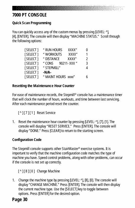
Quick Scan Programming
You can quickly access any of the custom menus by pressing [LEVEL: ^],[3], [ENTER]. The console will then display “CUSTOMIZE.” Scroll through thefollowing options:
[SELECT]“ MAX TIME” 0[SELECT]“CHANGE UNITS” 1[SELECT]“HR INPUTS” 2[SELECT]“LANGUAGE” 4
[SELECT]“CONTRAST ADJ” 5
7000 PT CONSOLE

Page 29
[SELECT]“CONTRAST ADJ” 5[SELECT]“MAX SPEED” - N/A- 6[SELECT]“CLINICAL MODE”-N/A- 7[SELECT]“SET DEFAULTS “ 9
Machine Status Codes
[ ^ ] [ 4 ] [ 0 ] display machine run time in hours[ ^ ] [ 4 ] [ 1 ] display number of workouts[ ^ ] [ 4 ] [ 2 ] display distance traveled[ ^ ] [ 4 ] [ 3 ] display software rev[ ^ ] [ 4 ] [ 4 ] display machine type[ ^ ] [ 4 ] [ 5 ] -N/A-[ ^ ] [ 4 ] [ 6 ] display machine run time in hours since last cleared
(used for maintenance)
1. Display the machine run time by pressing [LEVEL: ^], [4], [0]. The consolewill display “RUN HOURS XXXXX”.
2. Display the number of workouts by pressing [LEVEL: ^], [4], [1]. The consolewill display “WORKOUTS XXXX.”
3. Display the total distance covered up to date by pressing [LEVEL: ^], [4], [2].The console will then display “DISTANCE XXXX.”
4. Display the console software revision number by pressing [LEVEL: ^], [4],[3]. The console will display “CONS 92111-XXX.”
5. Display the machine type by pressing [LEVEL: ^], [4], [4]. The console willdisplay “STEPPER (or other machine type).”
6. Display the machine run time since last cleared by pressing [LEVEL: ^], [4],[6]. The console will display “MAINT HOURS XXXX.”
7000 PT CONSOLE
Page 30
Quick Scan Programming
You can quickly access any of the custom menus by pressing [LEVEL: ^],[4], [ENTER]. The console will then display “MACHINE STATUS.” Scroll throughthe following options:
[ SELECT ] “ RUN HOURS XXXX” 0[ SELECT ] “ WORKOUTS XXXX” 1[ SELECT ] “ DISTANCE XXXX” 2[ SELECT ] “ CONS 90211- XXX ” 3[ SELECT ] “ STEPMILL” 4[ SELECT ] -N/A-[ SELECT ] “ MAINT HOURS xxxx” 6
Resetting the Maintenance Hour Counter
For ease of maintenance records, the Stepmill® console has a maintenance timerthat will clock the number of hours, workouts, and time between last servicing.After each maintenance period reset the counter.
[ ^ ] [ 7 ] [ 1 ] Reset Service
1. Reset the maintenance hour counter by pressing [LEVEL: ^], [7], [1]. Theconsole will dusplay “RESET SERVICE.” Press [ENTER]. The console willdisplay “DONE.” Press [CLEAR] to return to the starting screen.
Configuration Code
The Stepmill console supports other StairMaster® exercise systems. It isimportant to verify that the machine configuration code matches the type ofmachine you have. Speed control problems, along with other problems, can occurif the console is not set up correctly.
[ ^ ] [ 8 ] [ 0 ] Change Machine
1. Change the machine type by pressing [LEVEL: ^], [8], [0]. The console willdisplay “CHANGE MACHINE.” Press [ENTER]. The console will then displaythe current machine type. Use the [SELECT] key to toggle betweenoptions. Press [ENTER] for the desired option.
7000 PT CONSOLE
Page 31
MAINTENANCE INSTRUCTIONS
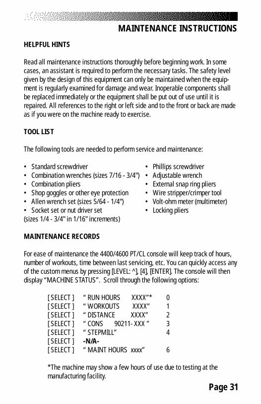
HELPFUL HINTS
Read all maintenance instructions thoroughly before beginning work. In somecases, an assistant is required to perform the necessary tasks. The safety levelgiven by the design of this equipment can only be maintained when the equip-ment is regularly examined for damage and wear. Inoperable components shallbe replaced immediately or the equipment shall be put out of use until it isrepaired. All references to the right or left side and to the front or back are madeas if you were on the machine ready to exercise.
TOOL LIST
The following tools are needed to perform service and maintenance:
• Standard screwdriver • Phillips screwdriver• Combination wrenches (sizes 7/16 - 3/4") • Adjustable wrench• Combination pliers • External snap ring pliers• Shop goggles or other eye protection • Wire stripper/crimper tool• Allen wrench set (sizes 5/64 - 1/4") • Volt-ohm meter (multimeter)• Socket set or nut driver set • Locking pliers(sizes 1/4 - 3/4" in 1/16" increments)
MAINTENANCE RECORDS
For ease of maintenance the 4400/4600 PT/CL console will keep track of hours,number of workouts, time between last servicing, etc. You can quickly access anyof the custom menus by pressing [LEVEL: ^], [4], [ENTER]. The console will thendisplay “MACHINE STATUS”. Scroll through the following options:
[ SELECT ] “ RUN HOURS XXXX”* 0[ SELECT ] “ WORKOUTS XXXX” 1[ SELECT ] “ DISTANCE XXXX” 2[ SELECT ] “ CONS 90211- XXX ” 3[ SELECT ] “ STEPMILL” 4[ SELECT ] -N/A-[ SELECT ] “ MAINT HOURS xxxx” 6
*The machine may show a few hours of use due to testing at themanufacturing facility.
Page 32
MAINTENANCE INSTRUCTIONS
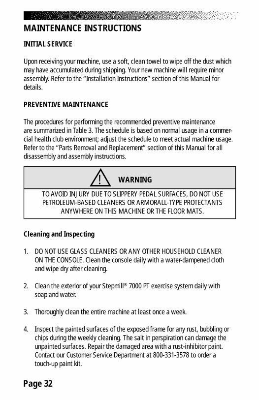
INITIAL SERVICE
Upon receiving your machine, use a soft, clean towel to wipe off the dust whichmay have accumulated during shipping. Your new machine will require minorassembly. Refer to the “Installation Instructions” section of this Manual fordetails.
PREVENTIVE MAINTENANCE
The procedures for performing the recommended preventive maintenanceare summarized in Table 3. The schedule is based on normal usage in a commer-cial health club environment; adjust the schedule to meet actual machine usage.Refer to the “Parts Removal and Replacement” section of this Manual for alldisassembly and assembly instructions.
Cleaning and Inspecting
1. DO NOT USE GLASS CLEANERS OR ANY OTHER HOUSEHOLD CLEANERON THE CONSOLE. Clean the console daily with a water-dampened clothand wipe dry after cleaning.
2. Clean the exterior of your Stepmill® 7000 PT exercise system daily withsoap and water.
3. Thoroughly clean the entire machine at least once a week.
4. Inspect the painted surfaces of the exposed frame for any rust, bubbling orchips during the weekly cleaning. The salt in perspiration can damage theunpainted surfaces. Repair the damaged area with a rust-inhibitor paint.Contact our Customer Service Department at 800-331-3578 to order atouch-up paint kit.
! WARNING
TO AVOID INJURY DUE TO SLIPPERY PEDAL SURFACES, DO NOT USEPETROLEUM-BASED CLEANERS OR ARMORALL-TYPE PROTECTANTS
ANYWHERE ON THIS MACHINE OR THE FLOOR MATS.

Page 33
5. Clean the step hinges carefully. Perspiration tends to accumulate in thehinges, and this can lead to eventual corrosion.
6. Inspect the Poly-V belt for excessive wear during the weekly cleaning.Adjust the belt tension if necessary.
Lubrication
The StairMaster® Stepmill® 7000 PT exercise system has six components thatrequire periodic lubrication: the drive chain, the two step chains, the two bearingplates and the step hinges. These parts are shown in the figure below. You willneed to remove the side covers to lubricate the chains and the bearing plates.
1. Place a protective mat on the floor while you are lubricating yourmachine. A rubber floor mat is available from StairMaster Health & FitnessProducts, Inc.
MAINTENANCE INSTRUCTIONS
Page 34
2. Lubricate the chains monthly with 30W motor oil. Drip the oil onto thechain plates and rollers. Let the oil soak in for a few minutes and thenremove any excess oil with a dry rag.
3. Remove the chains every three months to thoroughly clean and lubricatethem. Use a mild degreaser and a stiff brush to remove dirt and corrosionfrom the chain. Read the instructions on the degreaser container beforeusing.
4. Clean each bearing plate and lubricate it with multipurpose grease everythree months. The plate is lubricated to reduce friction when the stepshaft bearings roll over the plate.
5. Once per month, use 30W motor oil or brush light bearing grease into thestep hinges to lubricate the hinges and to prevent corrosion. Wipe off allexcess lubricant.
MAINTENANCE INSTRUCTIONS
! WARNING
TO REDUCE THE POSSIBILITY OF SLIPPING, BE SURETHE STEP AREA IS FREE OF GREASE OR OIL. WIPE ANY
EXCESS OIL OFF THE MACHINE SURFACES.
Page 35
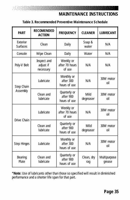
Table 3. Recommended Preventive Maintenance Schedule
*Note: Use of lubricants other than those so specified will result in diminishedperformance and a shorter life span for that part.
MAINTENANCE INSTRUCTIONS
TRAP DEDNEMOCERNOITCA YCNEUQERF RENAELC TNACIRBUL
roiretxEsecafruS naelC yliaD &paoS
retaw A/N
elosnoC naelCepiW yliaD retaW A/N
tleBV-yloPdnatcepsnI
fitsujdayrassecen
roylkeeWsruoh07retfa
esufoA/N A/N
niahCpetSylbmessA
etacirbuLroylhtnoM
003retfaesufosruoh
A/N rotomW03lio
dnanaelCetacirbul
roylretrauQ009retfa
esufosruoh
dliMresaerged
rotomW03lio
niahCevirD
etacirbuLroylkeeW
sruoh07retfaesufo
A/N rotomW03lio
dnanaelCetacirbul
roylretrauQ009retfa
esufosruoh
dliMresaerged
rotomW03lio
segniHpetS etacirbuLroylhtnoM
003retfaesufosruoh
A/N rotomW03lio
gniraeBetalP
dnanaelCetacirbul
roylretrauQ009retfa
esufosruoh
yrd,naelCgar
esoprupitluMesaerg

Page 36
TROUBLESHOOTING
GENERAL TROUBLESHOOTING GUIDELINES
This section outlines several tests to systematically identify and isolate thecause of problems in the electrical system and the drive train. This troubleshoot-ing section is organized into four basic problem sections: Electrical System,Console Diagnostics, Speed Control, and the Drive Train. The first step is toidentify the problem. Once you have identified the problem, perform all the testsin exactly the same order as written. Refer to the “Parts Removal and Replace-ment” section of this Manual for all disassembly and assembly instructions. Toorder a replacement part, or to get help with the troubleshooting process,contact our Customer Service Department at 800-331-3578. Internationalcustomers should contact their local distributor or call 425-823-1825.
TROUBLESHOOTING THE ELECTRICAL SYSTEM
The electrical system consists of: the power supply, main cable, relay board, loadresistor, and the console. In order to identify the component that is causing theproblem, you must systematically test the system. You will need a volt-ohmmeter (multimeter) to conduct portions of the following procedures. The consoleand power supply are not serviceable by the owner. If either of these parts areinoperable, they must be replaced. Opening the console or the power supply willvoid the warranty.
The Console Fails to Power Up
A. Perform a visual check of the machine. Check the following things first:
1. Is the power supply plugged in?
2. Is the indicator light lit on the power supply? If it is, proceed to step#3. If the light is not on, go to step B.
3. Replace or exchange your console with a console you know is goodand retest the machine.
B. Verify AC power.
1. Disconnect the AC power cord from the AC wall outlet.
Page 37
TROUBLESHOOTING THE ELECTRICAL SYSTEM
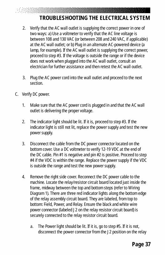
2. Verify that the AC wall outlet is supplying the correct power in one oftwo ways: a) Use a voltmeter to verify that the AC line voltage isbetween 108 and 130 VAC (or between 208 and 240 VAC, if applicable)at the AC wall outlet; or b) Plug in an alternate AC-powered device (alamp, for example). If the AC wall outlet is supplying the correct power,proceed to step #3. If the voltage is outside the range or if the devicedoes not work when plugged into the AC wall outlet, consult anelectrician for further assistance and then retest the AC wall outlet.
3. Plug the AC power cord into the wall outlet and proceed to the nextsection.
C. Verify DC power.
1. Make sure that the AC power cord is plugged in and that the AC walloutlet is delivering the proper voltage.
2. The indicator light should be lit. If it is, proceed to step #3. If theindicator light is still not lit, replace the power supply and test the newpower supply.
3. Disconnect the cable from the DC power connector located on thebottom cover. Use a DC voltmeter to verify 12-19 VDC at the end ofthe DC cable. Pin #1 is negative and pin #2 is positive. Proceed to step#4 if the VDC is within the range. Replace the power supply if the VDCis outside the range and test the new power supply.
4. Remove the right side cover. Reconnect the DC power cable to themachine. Locate the relay/resistor circuit board located just inside theframe, midway between the top and bottom steps (refer to WiringDiagram 1). There are three red indicator lights along the bottom edgeof the relay assembly circuit board. They are labeled, from top tobottom: Field, Power, and Relay. Ensure the black and white wirepower connector (labeled J2 on the relay resistor circuit board) issecurely connected to the relay resistor circuit board.
a. The Power light should be lit. If it is, go to step #5. If it is not,disconnect the power connector from the J2 position on the relay

Page 38
TROUBLESHOOTING THE ELECTRICAL SYSTEM
assembly circuit board (refer to Wiring Diagram 2). Use a DCvoltmeter to measure the VDC at the power connector. Pin #1is negative and Pin#10 is positive. The reading should be between12 and 19 VDC. If you are not getting power to the connector,replace the power connector assembly and retest.
b. If you are getting the correct voltage at the power connector,reconnect it to the J2 position on the relay assembly circuitboard. Disconnect the main cable connector at the J1 position ofthe relay assembly circuit board. Check the VDC reading at thesilver tabs on the relay assembly circuit board. Tab #4 (labelled +/WHT) is positive and tab #5 (labelled GND/BLK) is negative (referto Wiring Diagram 2). You should get a reading between 12 and19 VDC. If your reading is not within the range, replace the relayassembly circuit board and retest.
c. If you are getting the correct voltage at tabs #4 and #5, check theVDC reading at the connector labeled position J1 on the relayassembly circuit board. Pin #4 is positive and pin #5 is negative.You should get a reading between 12 and 19 VDC. If yourreading is not within the range, replace the relay assembly circuitboard and retest.
d. If all of the above power tests produce VDC readings that arewithin range and the Power indicator light is still not lit, thePower indicator light is probably inoperable. Replace the relayassembly circuit board, reconnect all wires, and retest.
5. Remove the console and disconnect the console cable. Use a DCvoltmeter to measure the VDC at pin #1 (negative) and pin #10 (positive)of the console cable connector. You should get a reading between 12and 19 VDC. If the reading is not within the range, replace the cableassembly and retest.

Page 39
CONSOLE DIAGNOSTIC TESTS
The following tests are performed while the console is in the “SELECTWORKOUT” mode. If the console fails any test, the console should be replaced orexchanged. To return to the “SELECT WORKOUT” mode, press either [CLEAR] or[START/STOP] while in the DIAGNOSTIC mode. Please note that there may beaddition verbiage on the display other than is listed in this manual. The Stepmill®
7000 PT console is used on other StairMaster® equipment.
Diagnostic Codes
[ ^ ] [ 6 ] [ 0 ] Test display[ ^ ] [ 6 ] [ 1 ] Test keyboard[ ^ ] [ 6 ] [ 2 ] Test serial port[ ^ ] [ 6 ] [ 3 ] Test alternator[ ^ ] [ 6 ] [ 4 ] -N/A-[ ^ ] [ 6 ] [ 5 ] -N/A-[ ^ ] [ 6 ] [ 6 ] Test Tach[ ^ ] [ 6 ] [ 7 ] - [ 6 ] [ 9 ] -N/A-
The Display Test
During the display test, the console screen alternates between all LCD segmentsturned on, and sample program profile screen at a 2-second rate.
1. Press [ LEVEL: ^ ], [ 6 ], [ 0 ], [ENTER]. The console will display“DISPLAY TEST”.
2. All LCD segments will turn on for 2 seconds and then a sampleprogram profile will be displayed for 2 seconds. Press [CLEAR] to endthe test.
The Keypad Test
Perform this test if you are having trouble entering data into the console.During the test, pressing any key displays that key name on the message line.Press [CLEAR] to exit.
1. Press [ LEVEL: ^ ], [ 6 ], [ 1 ], [ENTER] to start the test.

Page 40
CONSOLE DIAGNOSTIC TESTS
2. Firmly press each button except [CLEAR]. The name of the key will beshown in the display window. Press [CLEAR] to end the test.
The Serial Port Test
This test verifies that the RS 232 port used for linking to commercial entertain-ment systems is working. You must have the loop-back cable assembly, pn040051-001 to perform this test.
1. Insert the loop-back cable assembly into the RS 232 port on the backof the console.
2. Press [ LEVEL: ^ ], [ 6 ], [ 2 ], [ENTER], to start the test.
3. The console will run a diagnostic test and then display either “PASS”or “FAIL”. Replace the console if it fails this test.
The Alternator Test
Use this test to verify the alternator field routines of the console. You will needto briefly exercise on the machine for this test.
1. Press [ LEVEL: ^ ], [ 6 ], [ 3 ], [ENTER], to start the test.
2. For “Field on” press [ LEVEL: ^]. Step on the machine forapproximately 10 to 15 seconds. If full resistance is achieved duringthis time, your console has correct current flow. If no resistance isachieved, either the console or the alternator is bad. See theelectrical troubleshooting portion of this manual to isolate and testthe alternator. Replace the console if the alternator is good.
3. For ‘Field off” press [ LEVEL: V]. Step on the machine forapproximately 10 to 15 seconds. You should not get resistance withthe field turned off. Press [CLEAR] to end the test.
Page 41
CONSOLE DIAGNOSTIC TESTS
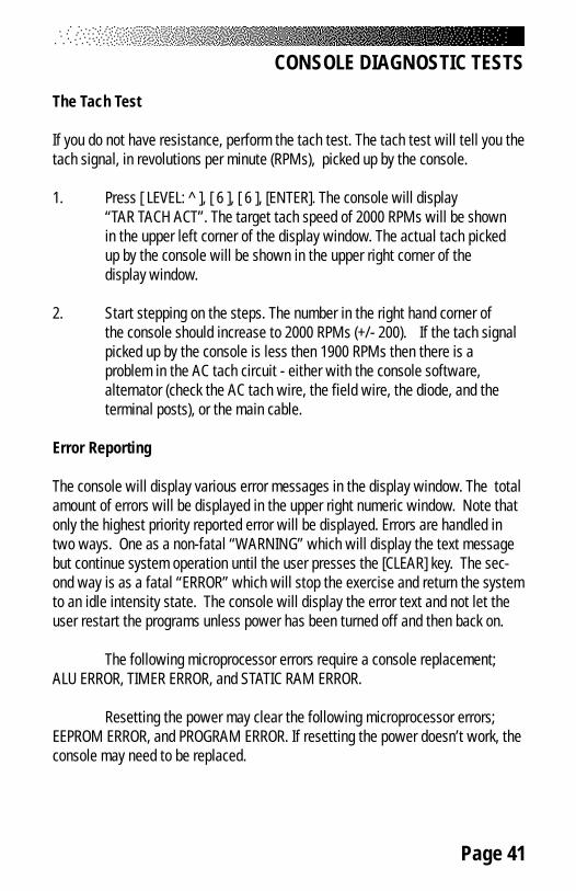
The Tach Test
If you do not have resistance, perform the tach test. The tach test will tell you thetach signal, in revolutions per minute (RPMs), picked up by the console.
1. Press [ LEVEL: ^ ], [ 6 ], [ 6 ], [ENTER]. The console will display“TAR TACH ACT”. The target tach speed of 2000 RPMs will be shownin the upper left corner of the display window. The actual tach pickedup by the console will be shown in the upper right corner of thedisplay window.
2. Start stepping on the steps. The number in the right hand corner ofthe console should increase to 2000 RPMs (+/- 200). If the tach signalpicked up by the console is less then 1900 RPMs then there is aproblem in the AC tach circuit - either with the console software,alternator (check the AC tach wire, the field wire, the diode, and theterminal posts), or the main cable.
Error Reporting
The console will display various error messages in the display window. The totalamount of errors will be displayed in the upper right numeric window. Note thatonly the highest priority reported error will be displayed. Errors are handled intwo ways. One as a non-fatal “WARNING” which will display the text messagebut continue system operation until the user presses the [CLEAR] key. The sec-ond way is as a fatal “ERROR” which will stop the exercise and return the systemto an idle intensity state. The console will display the error text and not let theuser restart the programs unless power has been turned off and then back on.
The following microprocessor errors require a console replacement;ALU ERROR, TIMER ERROR, and STATIC RAM ERROR.
Resetting the power may clear the following microprocessor errors;EEPROM ERROR, and PROGRAM ERROR. If resetting the power doesn’t work, theconsole may need to be replaced.
Page 42
The Telemetry (Polar®) Heart Rate Test
The telemetry heart rate system is made up of the console, the heart rate re-ceiver, and the chest strap (available separately). You can test each componentby performing the following steps:
1. You will need to put a chest strap on in order to test the telemetryheart rate. Before you put on the chest strap, wet the two contactpatches. Secure the chest strap as high under your pectoral muscles(chest) as is comfortable. The chest strap should fit snugly,comfortably, and allow normal breathing.
2. A flashing ♥ should be displayed on the console. Your heart rate, inbeats per minute, will show next to the heart icon. If the heart icondoes not show, or if your heart rate is not displayed on the consolethen you have a problem with either the console, chest strap, orheart rate receiver.
3. Verify that the console software has been set up to receive telemetry(see the heart rate monitoring section of this manual). Note thatholding the contact heart rate sensors (if enabled) can inhibit thetelemetry heart rate input from working.
4. Test your chest strap with a machine that you know is working, orwith a heart rate watch that you know is working.
5. If possible, replace or exchange your console with a machine that youknow is working and retest the machine.
6. Excess false heart rate detection: the telemetry receiver located in theconsole is susceptible to mechanical vibration as well as external elec-trical interference. Hitting the console or the frame may momentarilycause errant heart beat detection - this is normal. If excessive falseheart beats appear only during workouts, check that the console cableis not curled up behind the console. Pull as much of the cable down andaway from the console as possible. False heart beats while the machineis idle are most likely due to external interference. Try plugging the ma-chine into a different outlet, or moving it to a new location.
CONSOLE DIAGNOSTIC TESTS

Page 43
SPEED CONTROL PROBLEMS
If you have problems with erratic speed control while operating the machine, thecause may be either electrical or mechanical in nature. You will have to removethe side covers to conduct most of these tests.
A. Perform a visual check of the machine. Check the following things first:
1. Inspect the Poly- V belt for proper tension and excessive wear. A loosebelt will cause excessive noise and wear. The machine will run slug-gishly if the belt is too tight.
2. Replace a worn or frayed Poly-V belt. Adjust the belt so that there is 1/10" (0.3 cm) deflection at a point midway between the alternator andtransmission pulleys with fingertip pressure (See Drawing Below).
3. Check for proper wire connections on the alternator, relay assemblycircuit board, and load resistor (See Drawing Below).

Page 44
SPEED CONTROL PROBLEMS
4. Replace or exchange the console with another console you know isgood and retest the machine.
B. Check the relay assembly circuit board while the console displays "SELECTWORKOUT." You will need an assistant to complete the test of therelay assembly circuit board.
1. Remove the right side cover. Locate the relay assembly circuit boardlocated just inside the frame, midway between the top and bottomsteps (refer to Wiring Diagram). There are three red indicator lightsalong the bottom edge of the circuit board. They are labeled, from topto bottom: Field, Power, and Relay. Ensure the black and white wirepower connector (labeled J2 on the relay assembly circuit board) issecurely connected to the relay assembly circuit board (refer to FigureBelow).
2. If the Power light is lit, go to step #3. If it is not, perform the tests asdescribed in step 4b - c of the “Console Fails to Power Up” section.
3. The relay indicator light should be lit. If it is lit, proceed to step #5. If itis not, use a jumper wire on the relay assembly circuit board. Jumpthe silver tabs #1 (labeled RLY/RED) and #5 (labeled GRD/BLK) (refer
Page 45
SPEED CONTROL PROBLEMS
to Figure on page. 34). The relay indicator should light up. If it does, goto step #4. If the relay indicator does not light up, the relay assemblycircuit board must be replaced. Replace the relay assembly circuitboard and retest the machine.
4. You must check the cable assembly for continuity if the relay indicatorlit up when you jumped tabs #1 and #5.
a. Unplug the main cable from the position labeled J1 on the relayassembly circuit board. Disconnect the console cable from theback of the console. Set your multimeter to the continuity checkmode; on most meters, this will be the resistance or ohms setting.
b. Place one lead of the multimeter on pin #1 at the consoleconnector end of the console cable (refer to Wiring Diagram).Place the other lead on pin #1 at the end of the main cable youdisconnected from the relay assembly circuit board. You will get areading of near zero ohms if there is continuity in the cableassembly.
c. Check continuity in both ends of the main cable assembly at pin#5.
d. If there is no continuity in the cable assembly at either pin,replace the cable assembly and retest. If there is continuity in thecable assembly at both pins and the relay resistor indicator is notlit, the console is inoperable and must be replaced.
5. Have your assistant step on the staircase (leave the console in theATTRACT mode) while you check the field indicator light. It should beflickering. If it is and you still have a speed control problem, go to step#6.
If it is not flickering, ensure the following: the console cable isconnected to the console; the console/main cable connection issecure; the connector at position J1 on the relay assembly circuitboard is securely connected; that there is continuity in the cableassembly. To check for continuity:

Page 46
SPEED CONTROL PROBLEMS
a. Unplug the connector at position J1 on the relay assembly circuitboard. Disconnect the console cable from the back of theconsole. Set your multimeter to the continuity check mode; onmost meters this will be the resistance or ohms setting.
b. Place one lead of the multimeter on pin #2 at the consoleconnector end of the console cable. Place the other lead on pin#2 at the end of the main cable you disconnected from the relayassembly circuit board. You will get a reading of near zero ohms ifthere is continuity in the cable assembly.
c. If there is no continuity in the cable assembly, replace it andretest. If there is continuity in the cable assembly and the fieldindicator light is still not flickering, contact the Customer ServiceDepartment at 800-331-3578 for further assistance.
6. If the field indicator was flickering while your assistant was on themachine and you still have a problem with speed control, you need totest the alternator.
a. Disconnect the white wire (labeled positive output on thealternator) and the brown wire (labeled “Field” on the alternator).Use a jumper wire to jump the Field and positive output terminalsof the alternator.
b. Have your assistant step onto the staircase. Does the staircaseslow down? If it does not, you need to replace the alternator. Ifthe staircase does slow down, contact the Customer ServiceDepartment for further assistance.
c. Replace or exchange the alternator with another alternator youknow is good and retest the machine.
d. Test the load resistor as outlined in the "Load Resistor Test"section of this Manual. If the speed control problem still exists,contact the Customer Service Department at (800) 331-3578 forfurther assistance.

Page 47
LOAD RESISTOR TEST
The alternators are heavy-duty models designed to withstand the rigors ofcommercial use. One possible reason for repeated failure is an inoperable loadresistor. To test the load resistor:
1. Unplug the AC power cord from the AC wall outlet.
2. Locate the load resistor mounted to the relay board assembly just underthe staircase.
3. Disconnect one black wire from the resistor (See Drawing Below).
4. Set your multimeter for R x 1 or the lowest available resistance range. Ifyou have an analog multimeter, touch the two leads together and adjustthe meter for a zero reading.
5. Place one lead on Tab A and one lead on Tab 5 of the relay assemblycircuit board (See Drawing Below). You should get a reading ofapproximately 1.0 ohm or less.
6. Replace the load resistor if the reading is out of range and retest the newload resistor.
7. Reconnect the AC power cord and reinstall the right side cover.
8. If the problem still exists, contact the Customer Service Department at(800) 331-3578 for further assistance.

Page 48
If you hear a grinding or clicking noise, or experience excessive vibration duringexercise, or if the steps are not functioning properly, you probably have aproblem in the drive train. Attempt to isolate the problem area by performing thefollowing tests in precisely the order listed below. Refer to the “Parts Removaland Replacement” Section of this Manual for all disassembly and assemblyinstructions.
1. Unplug the power supply from the AC wall outlet and remove the sidecovers.
2. Check the condition and the tension level of the Poly-V belt. Replace thebelt if it is excessively worn.
a. Adjust the tension level so that you can deflect either side of thebelt 1/10" (0.3 cm) at the center between the alternator and thetransmis sion pulleys (See Drawing Below). Noise can be generatedby a belt that is too tight or too loose.
b. If the noise is still present, remove the Poly-V belt and rotate thestaircase without standing on it. With the Poly-V belt removed, thestaircase will rotate very quickly.
c. If the noise no longer exists, replace the alternator.
TROUBLESHOOTING THE DRIVE TRAIN
WARNINGTO REDUCE THE RISK OF INJURY, DO NOT OPERATE THE MACHINE
WHILE THE SIDE COVERS ARE REMOVED. DO NOT ROTATE THE STAIRSWHILE ANYONE'S HANDS ARE INSIDE THE MACHINE.
!

Page 49
TROUBLESHOOTING THE DRIVE TRAIN
3. Check the condition of the alternator.
a. Unplug the alternator from the relay board and remove the Poly-Vbelt.
b. Spin the alternator pulley with your fingers. It should spin freely andremain spinning for at least one and one-half revolutions. If it doesnot spin as it should, the bearings may be bad and the alternatorshould be replaced.
c. If the pulley does spin freely, check the alternator for noise,roughness, or the presence of black powder inside the alternator ornear the outside of the case. If any of these conditions exist, thebrushes may be bad and the alternator should be replaced.
d. Reconnect the Poly-V belt and adjust the belt tension.
4. Check the drive chain mechanism. Rotate the stairs and look for chainlinks that do not flex as the chain travels over the sprockets. If the links arefrozen or sticking, replace the chain.
5. Check the transmission.
a. Rotate the steps by hand and listen for the noise.
b. If you hear the noise, remove the drive chain and the Poly-V belt.Rotate the steps by hand again and listen for the noise. If the noisehas gone away, replace the transmission.
6. Check the step chain assemblies.
a. Have your assistant slowly exercise on the machine. Observe thestaircase. If the staircase moves to the left or right during exercise,ensure the set screws in the bearing adjusters are tight.
b. Rotate the stairs and look for chain links that do not flex as the chaintravels over the sprockets. If the links are frozen or sticking, replacethe chain.
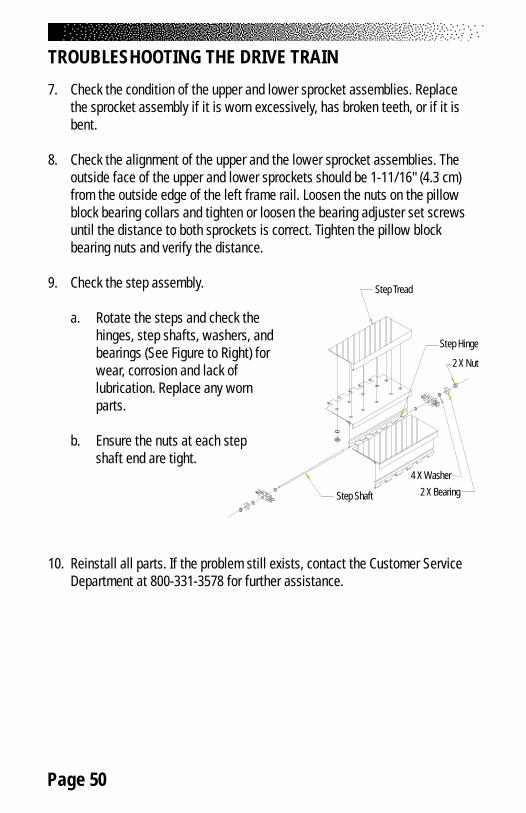
Page 50
TROUBLESHOOTING THE DRIVE TRAIN
7. Check the condition of the upper and lower sprocket assemblies. Replacethe sprocket assembly if it is worn excessively, has broken teeth, or if it isbent.
8. Check the alignment of the upper and the lower sprocket assemblies. Theoutside face of the upper and lower sprockets should be 1-11/16" (4.3 cm)from the outside edge of the left frame rail. Loosen the nuts on the pillowblock bearing collars and tighten or loosen the bearing adjuster set screwsuntil the distance to both sprockets is correct. Tighten the pillow blockbearing nuts and verify the distance.
9. Check the step assembly.
a. Rotate the steps and check thehinges, step shafts, washers, andbearings (See Figure to Right) forwear, corrosion and lack oflubrication. Replace any wornparts.
b. Ensure the nuts at each stepshaft end are tight.
10. Reinstall all parts. If the problem still exists, contact the Customer ServiceDepartment at 800-331-3578 for further assistance.
Step Tread
Step Hinge
Step Shaft
4 X Washer
2 X Bearing
2 X Nut

Page 51
COVERS
There are five covers on the machine: two side covers, a back cover, a bottomcover, and a top cover. The side covers overlap the top cover. The side coversmust be removed before the top cover and/or the bottom cover can be removed.
All covers are held in place with reusable plastic fasteners (refer to Figure 5for their location). To remove the fasteners, slide either end of the fastenerremoval tool under the edge of the pin head (refer to Figure 6). The pin should notbe removed. Pull the cover away from the frame. Do NOT use the fastenerremoval tool or any other sharp tool to pry out the fastener base because youmay damage the covers - use the fastener removal tool to remove the pin.
To reinstall the fastener, insert the base of the fastener through the coverand into the frame. When the base is in place, push the pin in all the way tosecure the fastener.
Side Covers
1. Remove the 14 fasteners on each side cover.
2. Pull the cover away from the frame.
Top Cover
1. Remove both side covers.
2. Lift the top cover away from the frame.
3. Set the top cover in place. Secure the side covers to completereinstallation.
PARTS REMOVAL AND REPLACEMENT
TO REDUCE THE RISK OF INJURY, DO NOT OPERATE THE MACHINE WHILETHE SIDE COVERS ARE REMOVED. DO NOT ROTATE THE STAIRS WHILE
ANYONE'S HANDS ARE INSIDE THE MACHINE.
! WARNING
Page 52
PARTS REMOVAL AND REPLACEMENT
Back Cover
1. Remove the 8 fasteners and lift the back cover away from the frame.
2. Align the holes in the frame and the back cover. Secure the back coverwith the 8 fasteners.
Bottom Cover
1. Remove both side covers to gain access to the bottom cover fasteners.
2. Disconnect the DC power cable.
3. Remove the six fasteners and remove the bottom cover from the frame.
4. Reinstall the bottom cover, then the two side covers. Remember toconnect the DC power cable.
CONSOLE
1. Locate the mounting knobs on the back of the console (See cutaway viewBelow).
2. Loosen and remove the four mounting knobs and lock washers.
3. Lift up the console and unplug the console cable from the back of theconsole.
4. Remove the console from the frame.
5. Reinstall the console by reversingthe steps.
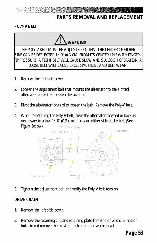
Page 53
POLY-V BELT
1. Remove the left side cover.
2. Loosen the adjustment bolt that mounts the alternator to the slottedalternator brace then loosen the pivot nut.
3. Pivot the alternator forward to loosen the belt. Remove the Poly-V belt.
4. When reinstalling the Poly-V belt, pivot the alternator forward or back asnecessary to allow 1/10" (0.3 cm) of play on either side of the belt (SeeFigure Below).
5. Tighten the adjustment bolt and verify the Poly-V belt tension.
DRIVE CHAIN
1. Remove the left side cover.
2. Remove the retaining clip and retaining plate from the drive chain masterlink. Do not remove the master link from the drive chain yet.
PARTS REMOVAL AND REPLACEMENT
THE POLY-V BELT MUST BE ADJUSTED SO THAT THE CENTER OF EITHERSIDE CAN BE DEFLECTED 1/10" (0.3 CM) FROM ITS CENTER LINE WITH FINGER-TIP PRESSURE. A TIGHT BELT WILL CAUSE SLOW AND SLUGGISH OPERATION; A
LOOSE BELT WILL CAUSE EXCESSIVE NOISE AND BELT WEAR.
! WARNING

Page 54
PARTS REMOVAL AND REPLACEMENT
3. Push up on the idler arm with one hand to relieve the tension on thedrive chain (See Drawing Below). Remove the master link from one end ofthe drive chain and remove the drive chain from the sprockets.
4. Install the new drive chain by reversing the steps.
STEP ASSEMBLY
1. Remove the right and the left side covers.
2. Rotate the stairs until the step you want to remove is positioned in themiddle of the staircase.
3. Loosen and remove the nut from one endof the step shaft on both the upper andthe lower hinges of that step (SeeFigure to Right).
4. Remove the bearing and the washerfrom each step shaft.
5. Grasp the opposite step retainingnut with pliers or locking pliers.Pull the step shaft out of theupper and lower step hinges.
Step Tread
Step Hinge
Step Shaft
4 X Washer
2 X Bearing
2 X Nut

Page 55
PARTS REMOVAL AND REPLACEMENT
Be careful to not lose the washer located between the step and themodified link.
Note: Each step assembly weighs approximately 15 lbs. Be aware of fingerplacement when removing the step assembly.
6. Reinstall the step by reversing the procedures.
STEP CHAIN ASSEMBLY
1. Remove the right and the left side covers.
2. Rotate the stairs to position the step chain master link on the lower spanof the chain. It may be necessary to reduce the chain tension to removethe master link. Perform the following steps to reduce the chain tension:
• Count and write down the number of exposed threads on the topbearing adjuster set screw for a reference when you reassemble theparts (SeeFigure Below).

Page 56
PARTS REMOVAL AND REPLACEMENT
• Loosen the nuts on the pillow block bearing housing.
• Loosen the bearing adjustment set screw until the chain tension levelis relieved to a point where the master link may be disconnected.
3. Remove the master link.
4. Using the old master link, connect the new chain assembly to the lowerhalf of the old chain assembly.
5. Remove the nut from the step shaft above the master link. It may benecessary to place another 5/16"-18 nut on the opposite end of the stepshaft to gain leverage and remove the nut.
6. Remove the bearing, the outer step shaft washer and the modified link ofthe old step chain assembly from the step shaft.
7. Place the modified link of the new step chain assembly on the step shaft.Reinstall the outer step shaft washer, bearing and nut.
8. Rotate the steps until the next step shaft is in approximately the sameplace as the previous step shaft.
9. Repeat steps 6-8 until the new chain assembly is installed on theremaining step shafts.
10. Remove the master link connecting the old chain with the new chain.
11. Connect the new chain assembly together with the master link. Tightenthe bearing adjustment set screw until the same number of threads as instep 2 are exposed. Tighten the nuts on the pillow block bearing housing.
12. You should consider replacing the opposite step chain so that both chainswill wear equally.
13. Reassemble the machine in reverse order.

Page 57
PARTS REMOVAL AND REPLACEMENT
UPPER (AND LOWER) SPROCKET ASSEMBLY
1. Remove the right and left side covers.
2. Remove all of the steps.
3. Remove the drive chain if you are removing the upper sprocket assembly.
4. Count and write down the number of exposed threads on the bearingadjuster set screws on both sides of the machine for a reference whenyou reassemble the parts (See Drawing Below).
5. Remove the right and left step chain assemblies.
6. Loosen the adjustment screws until the tips of the screws are flush withthe inside face of the bearing adjusters.

Page 58
PARTS REMOVAL AND REPLACEMENT
7. Have an assistant support the sprocket assembly. Loosen and remove thenuts on the pillow block bearing housing.
8. Remove the sprocket assembly from the frame.
9. Loosen the two set screws on both of the pillow block bearing collars andremove the pillow block bearings from the sprocket axle.
10. To reinstall the sprocket assembly:
• Slide the pillow block bearings on both ends of the sprocket axle. Donot tighten the set screw on the pillow block bearing collars yet.
• Place the bearing adjusters and the sprocket assembly onto the frameand start the pillow block bearing housing nuts onto the frame.
• Slide the sprocket assembly toward the front of the machine whiletightening the pillow block bearing housing nuts.
• Align the sprocket assembly. The outside face of the left sprocketshould be 1-11/16" (4.3 cm) from the outside edge of the left framerail. Move the sprocket axle within the pillow block bearing collar asneeded to get the correct distance.
• When the distance is correct, tighten the pillow block bearing collarset screw on the left and right sides of the machine.
• Loosen the pillow block bearing housing nuts slightly. Tighten thebearing adjuster set screws until the exact number of threads areexposed (refer to your notes taken earlier). Tighten the pillow blockbearing housing nuts.
• Check the alignment of the other sprocket at this time. If the distancefrom the outside edge of the left frame rail to the outside face of thesprocket is not 1-11/16" (4.3 cm), loosen the set screws on the leftand right side pillow block bearing collars and adjust the axle. Tightenthe pillow block bearing collar set screws on the machine and then goto step 11.
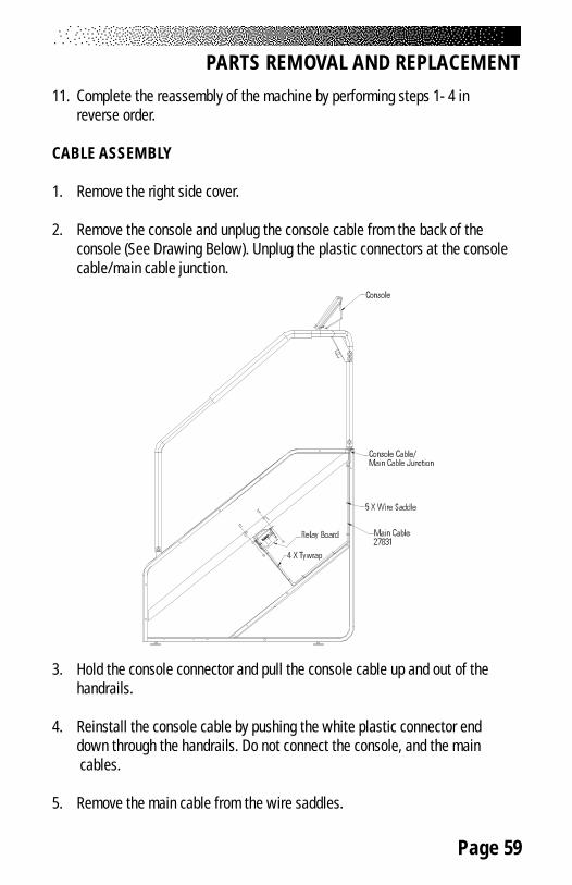
Page 59
PARTS REMOVAL AND REPLACEMENT
11. Complete the reassembly of the machine by performing steps 1- 4 inreverse order.
CABLE ASSEMBLY
1. Remove the right side cover.
2. Remove the console and unplug the console cable from the back of theconsole (See Drawing Below). Unplug the plastic connectors at the consolecable/main cable junction.
3. Hold the console connector and pull the console cable up and out of thehandrails.
4. Reinstall the console cable by pushing the white plastic connector enddown through the handrails. Do not connect the console, and the main cables.
5. Remove the main cable from the wire saddles.
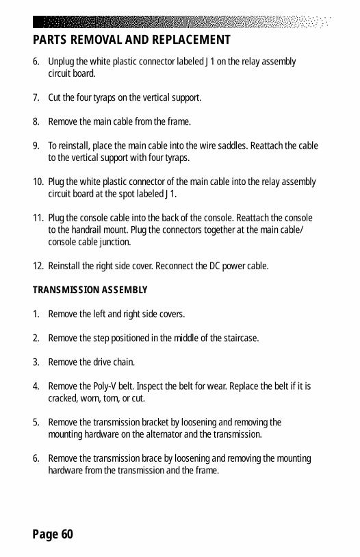
Page 60
PARTS REMOVAL AND REPLACEMENT
6. Unplug the white plastic connector labeled J1 on the relay assemblycircuit board.
7. Cut the four tyraps on the vertical support.
8. Remove the main cable from the frame.
9. To reinstall, place the main cable into the wire saddles. Reattach the cableto the vertical support with four tyraps.
10. Plug the white plastic connector of the main cable into the relay assemblycircuit board at the spot labeled J1.
11. Plug the console cable into the back of the console. Reattach the consoleto the handrail mount. Plug the connectors together at the main cable/console cable junction.
12. Reinstall the right side cover. Reconnect the DC power cable.
TRANSMISSION ASSEMBLY
1. Remove the left and right side covers.
2. Remove the step positioned in the middle of the staircase.
3. Remove the drive chain.
4. Remove the Poly-V belt. Inspect the belt for wear. Replace the belt if it iscracked, worn, torn, or cut.
5. Remove the transmission bracket by loosening and removing themounting hardware on the alternator and the transmission.
6. Remove the transmission brace by loosening and removing the mountinghardware from the transmission and the frame.

Page 61
7. Support the transmission while loosening and removing the fourtransmission mounting bolts. Remove the transmission and rubber padfrom the frame (See Drawing Below).
8. Reinstall the transmission by reversing the removal procedures.
9. Ensure the Poly-V belt is tensioned according to the procedures outlined inthe “Poly-V Belt” section of this Manual.
ALTERNATOR ASSEMBLY
1. Remove the right and left side covers.
2. Remove the step positioned in the middle of the staircase.
3. Remove the wiring from the alternator terminals, noting the origin and colorof the wires removed from each terminal.
PARTS REMOVAL AND REPLACEMENT

Page 62
4. Remove the Poly-V belt. Inspect the belt for wear. Replace the belt if it iscracked, worn, torn, or cut.
5. Remove the alternator adjustment bolt (See Drawing on Pg. 51).
6. Remove the nut, bolt and mounting hardware from the alternator bracket.Remove the alternator from the frame.
7. Reinstall the alternator by reversing the removal procedures. Be sure toverify the wiring connections.
8. Ensure the Poly-V belt is tensioned correctly (See Drawing Below).
RELAY/RESISTOR ASSEMBLY
1. Remove the left side cover.
2. Remove the step positioned in the middle of the staircase.
3. Remove the wiring from the alternator terminals, noting the origin and colorof the wires that are removed from each terminal.
4. Unplug the main cable connector from the J1 position on the relay circuitboard.
PARTS REMOVAL AND REPLACEMENT
Page 63
PARTS REMOVAL AND REPLACEMENT
5. Unplug the power connector from the J2 position on the relay circuit board.
6. Loosen and remove the four mounting bolts and remove the relay/resistorassembly from the frame.
7. Reinstall the relay/resistor assembly in the reverse order. Verify the wiringconnections before attaching the side cover.

Page 64
The machine must be grounded. If it should malfunction or break down, ground-ing provides the path of least resistance for the electric current, thereby reducingthe risk of electric shock. This machine is equipped with a cord having anequipment-grounding conductor and a grounding plug that looks like the plugillustrated in sketch A in the Drawing below. International machines may vary. Itmust be plugged into an appropriate outlet that is properly installed andgrounded in accordance with all local codes and ordinances.
A temporary adapter that looks like the adapter illustrated in sketches B andC may be used to connect this plug to a two-pole receptacle as shown in sketchB if a properly grounded outlet is not available. The temporary adapter should beused only until a properly grounded outlet (sketch A) can be installed by aqualified electrician. The green colored lug extending from the adapter must beconnected to a permanent ground such as a properly grounded outlet box cover.Whenever an adapter is used, it must be held in place by a metal screw.
GROUNDING INSTRUCTIONS
Figure 5: Grounding System
!IMPROPER CONNECTION OF THE EQUIPMENT-GROUNDING
CONNECTOR CAN RESULT IN THE RISK OF ELECTRIC SHOCK. CHECKWITH A QUALIFIED ELECTRICIAN OR SERVICE PERSON IF YOU ARE INDOUBT AS TO WHETHER THE MACHINE IS PROPERLY GROUNDED. DO
NOT MODIFY THE PLUG PROVIDED WITH THIS MACHINE. IF IT WILL NOTFIT THE AVAILABLE OUTLET, HAVE A PROPER OUTLET INSTALLED BY A
QUALIFIED ELECTRICIAN.
DANGER

Page 65
This equipment has been tested and found to comply with the limits for a Class Adigital device, pursuant to Part 15 of the FCC rules. These limits are designed toprovide reasonable protection against harmful interference when the equipmentis operated in a commercial environment. This equipment generates, uses, andcan radiate radio frequency energy and, if not installed and used in accordancewith the instruction manual, may cause harmful interference to radio communica-tions. Operation of equipment in a residential area may cause harmful interfer-ence in which case the user will be required to correct the interference at hisown expense.
CANADIAN DOC CLASS A COMPLIANCE
This digital apparatus does not exceed the Class A limits for radio emissionsfrom digital apparatus set out in the radio interference regulations of theCanadian Department of Communications.
La présent appareil numérique ne dépasse pas les limites etablies pour les bruitsradioélectriques applicables aux appareils numériques de la Class A prescritesdans les règlements sur le brouillage radioélectrique édicté par le Ministère desCommunications du Canada.
FCC COMPLIANCE
!CHANGES OR MODIFICATIONS TO EQUIPMENT NOT EXPRESSLY APPROVED BYSTAIRMASTER® HEALTH & FITNESS PRODUCTS, INC. COULD VOID THE USER’S
AUTHORITY TO OPERATE THIS EQUIPMENT.
WARNING

Page 66
IMPORTANT PHONE NUMBERS
If you need assistance, please have both the serial number of your machine andthe date of purchase available when you contact the appropriateStairMaster® Health & Fitness Products, Inc. office listed below.
OFFICES IN THE UNITED STATES
CORPORATE HEADQUARTERS CUSTOMER SERVICE12421 Willows Road NE, Suite 100 12421 Willows Road NE, Suite 100Kirkland, WA 98034 Kirkland, WA 98034(800) 635-2936 or (425) 823-1825 (800) 331-3578FAX: (425) 823-9490 FAX: (425) 814-0601www.stairmaster.com E-mail: customerservice@
stairmaster.com
INTERNATIONAL OFFICES AND DISTRIBUTORS
For technical assistance and a list of distributors in your area, please call or faxone of the following numbers.
INTERNATIONAL DIVISION ASIA PACIFIC HEADQUARTERS(425) 823-1825 Telephone/Fax:+81-45-590-5686FAX: (425) 820-7505 E-mail: [email protected]: [email protected]
EUROPE: HEADQUARTERS+41-91-827-3801FAX: +41-91-827-8902E-Mail: [email protected]
GERMANY: HEADQUARTERS+49-2204/610-27FAX: +49-2204/628-90E-Mail: [email protected]
U.K.: HEADQUARTERS+44-1908/267-345FAX: 44-1908/267-346E-mail: [email protected]

Page 67
FIGU
RES
Figure 6: Side Cover and Handrail A
ssemblies
Right Side Cover22547
Right Handrail22946-03
36 X 22086
Inside PanelRight - 24638Left - 24639
Left Side Cover22544
7 X 24757
Bottom Panel22563
Distribution DecalSerial Number Decal
Compliance Decal
8 X 22086
Back Panel21304
Left Handrail22947-03
Top Cover22555
Caution Decal
23 X 24757
Transport Wheel Assembly2 X 10262

Page 68
FIGURES
Figure 7: Cover Fasteners
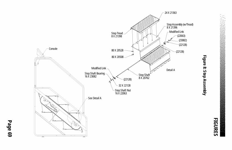
Page 69
FIGU
RES
Figure 8: Step Assem
bly
Console
See Detail A
Step Tread8 X 21398
80 X 20528
80 X 20508
Step Assembly (w/Tread)8 X 21396
Modified Link(22063)
(23082)(22128)
(22128)
Step Shaft8 X 20762(22128)
32 X 22128
Modified Link
Step Shaft Bearing16 X 23082
Step Shaft Nut16 X 22063
Detail A
24 X 21363

Page 70
FIGU
RES
Figure 9: Step Chain and Sprocket Assem
blies
Detail AModified Link40215
Chain Assembly (with Modified Links)2 X 10195
Chain Section, #405.5”4 X 20532
Master Link2 X 25305
See Detail A(23424-03) (10205-03)
Chain Section, #4011.5”4 X 20531
4 X 10037
8 X 22029
4 X 22039Pillow Block Bearing4 X 20012
8 X 200348 X 22030
Bearing Plate2 X 20682
8 X 22071
Upper Sprocket Assembly(42-Tooth Sprocket)23424-03
(22071)
6 X 22032
(22039)
2X 22072
(22071)
(22072)
Lower Sprocket Assembly10205-03

Page 71
FIGU
RES
Figure 10: Transmission and A
lternator Assem
blies
Drive Chain Assembly
Master Link25305
Upper Sprocket Assembly23424-03
Drive Chain23257
Poly-V Pulley21247
Transmission Assembly
23427
2 X 220372 X 22164
2 X 22435
(22038)
2 X 22026
22043
2000720693
22042(22036)
(22036)
(22037)
4 X 22036(22036)
(22038)22983 (22036)4 X 22038
1086022075
22146(22164)
(22038)(22435)
Frame
2054722139
10059
20202
Alternator20205Transmission Pulley
24662Transmission 20001
Transmission Pad20808
4 X 220274 X 22028 22163
22029
22030
2 X 22191
2 X 2219122433
20114
(22191)
Transmission Assembly Mounting to the Frame
Transmission Assembly23591
Transmission Assembly23591

Page 72
FIGU
RES
Figure 11: Wiring D
iagram
2 X 21363
10794-03
4 X 222132 X 246432 X 229374 X 22323
2 X 223232 X 222132464322097
Grommet15034
Console
4 X 22028
4 X 22036
(22933)
4 X 20473
Main Cable21769
5 X 23792
B
B
Section B-B
221092213422110
4 X 22663
Power Connector21768
W-3Field
W-5W-4W-3W-2W-1
W-6Ground
W-4AC Tap
W-5PositiveOutput
Cut-Away View of Polar Receiver
W-2
W-6
W-1
Relay/Resistor Assembly22933
Console Cable21416
Fastener, Hook22938Fastener, Loop22939
Grommet24663
Receiver, Polar®
Plug-in25165
Heart Rate Cap21765
Polar Cable Assy, 12”26143
Tywrap25233
4 X 223234 x 222134 x 246432 X 24640
Relay Board

Page 73
Figure 12: Relay Board
FIGURES

STEPMILL 7000OWNER’S MANUAL
®
ADDENDUM
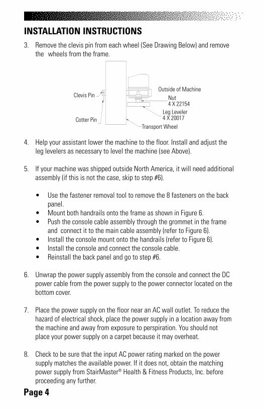
Page 4
3. Remove the clevis pin from each wheel (See Drawing Below) and removethe wheels from the frame.
4. Help your assistant lower the machine to the floor. Install and adjust theleg levelers as necessary to level the machine (see Above).
5. If your machine was shipped outside North America, it will need additionalassembly (if this is not the case, skip to step #6).
• Use the fastener removal tool to remove the 8 fasteners on the backpanel.
• Mount both handrails onto the frame as shown in Figure 6.• Push the console cable assembly through the grommet in the frame
and connect it to the main cable assembly (refer to Figure 6).• Install the console mount onto the handrails (refer to Figure 6).• Install the console and connect the console cable.• Reinstall the back panel and go to step #6.
6. Unwrap the power supply assembly from the console and connect the DCpower cable from the power supply to the power connector located on thebottom cover.
7. Place the power supply on the floor near an AC wall outlet. To reduce thehazard of electrical shock, place the power supply in a location away fromthe machine and away from exposure to perspiration. You should notplace your power supply on a carpet because it may overheat.
8. Check to be sure that the input AC power rating marked on the powersupply matches the available power. If it does not, obtain the matchingpower supply from StairMaster® Health & Fitness Products, Inc. beforeproceeding any further.
INSTALLATION INSTRUCTIONS
Cotter PinTransport Wheel
Leg Leveler4 X 20017
Nut4 X 22154
Outside of MachineClevis Pin

Page 66
IMPORTANT PHONE NUMBERS
If you need assistance, please have both the serial number of your machine andthe date of purchase available when you contact the appropriateStairMaster® Health & Fitness Products, Inc. office listed below.
OFFICES IN THE UNITED STATES INTERNATIONAL CUSTOMER SERVICEWORLDWIDE CUSTOMER SERVICE INTERNATIONAL OFFICE
North American Office Nautilus International S.A.16400 SE Nautilus Drive Rue Jean Prouve 6Vancouver, Washington, USA 98683 1762 Givisiez / SwitzerlandTel: 1-800-NAUTILUS (1-800-628-8458) Tel: +4-26-460-77-77FAX: 1-800-523-1049 Fax: +41-26-460-77-70E-mail: [email protected]
INTERNATIONAL OFFICES:Switzerland Office Germany and Austria OfficeNautilus Switzerland S.A. Nautilus GmbHTel: +41-26-460-77-66 Tel: +49-2203-20-20-0Fax: +41-26-460-77-60 Fax: +49-2203-20-20-4545
Italy Office United Kingdom OfficeNautilus Italy s.r.l. Nautilus UK Ltd.Tel: +39-051-664-6201 Tel: +44-1908-267-345Fax: +39-051-664-7461 Fax: +44-1908-267-346
China Office Nautilus Representative OfficeTel: +86-21-523-707-00Fax: +86-21-523-707-09

Page 67
FIGURES
Figure 6: Side Cover and Handrail Assemblies
revoC ed iS thgiR 2549
5
liardn aH thgi R 2557
9
68022 X 63
lenaP edi snI25
858
- thg iR25
859
- t feL
r evo C ediS tfeL 2557
7
75 742 X
7
le naP mottoB 25
575
laceD n oitubir ts iDla ceD rebmu N lair eS
lace D ec nailpmo C
6 8022 X 8
l ena P kca B 2557
3
liardnaH tfeL 2557
8
revoC poT 2549
4
laceD noi tua C
75742 X 32
ylbm ess A leeh
W t rop snarT262 01 X 2

Page 69
FIGURES
Figure 8: Step Assembly
elosnoC
A liat e D eeS
dae rT petS89312 X 8
tfahS petS22
849
X 8
A li ateD
3 6312 X 42
3627
1-00
1(Fo
am P
ads)
2549
6
2001
7
2549
2 (Fr
ame
with
Foot
Pad
s)
2549
3

Page 70
FIGURES
Figure 9: Step Chain and Sprocket Assemblies
y 2
X 27
268
l bmessA n iahC
) 30- 424 32 ()30-5 02 01(
724 22 X 8
gn ir aeB k c olB wolli P
21002 X 4
et alP g niraeB22
848
X 2
ylbmessA t ekcorpS reppU
)tekc orpS ht ooT-24(
ylbmessA te kcorpS re
woL30- 50201
2586
2
1003
7-03
2549
8
2342
4-03
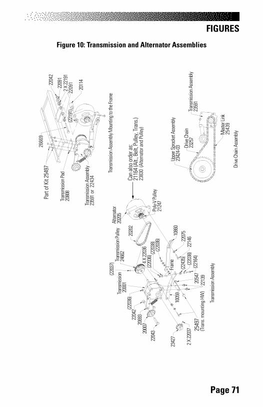
Page 71
FIGURES
Figure 10: Transmission and Alternator Assemblies
ylbm essA niahC evirD
kniL r etsaM 25
439
y lbme ssA t ekcor pS rep pU30-4 24 32
ni ahC evi rD752 32
y ellu P V-ylo P74212
ylb mes sA noi ssi ms na rT
72 432
73022 X 2
3402 2
700 0239 602
24 022) 63022(
)7302 2(
63 022 X 4)6 3022(
) 83 022()630 22(
068 01 5702 2 6412 2)46122 (
)83 022()534 22(
e ma rF
745029312 2
9 5001
2 020 2
rotanretlA5 0202
ye lluP nois sim sna rT2664 2
n oiss im snar T1 0002
d aP noissi ms narT80 802
2666
9
42 02 2 910 2219122 X 2 20
912
41102
)191 22(
emarF eht ot gnitn uoM yl bmessA nois sim snarT
ylbmessA noissimsnarT1
or 2
2434
953 2
yl bme ssA no iss im sna rT195 32
2549
7(T
rans
. mou
ntin
g HW
)
Can
also
ord
er a
s:21
164
(Alt.
, Bel
t, Pu
lley,
Tran
s.)23
830
(Alte
rnat
or a
nd P
ulle
y)
Part
of K
it 25
497

Page 72
FIGURES
Figure 11: Wiring Diagram
2558
1-01
323 22 X 2312 22 X 2
3464279022
tem
morG43051
2586
3 ) 3392 2(elbaC nia
M96712
29732 X 7
B
B
B- B noitceS
2586
9
r ot cenno C r ewoP
86712
3-W
dl ei F
5-W
4-W
3-W
2-W
1-W
6-W
dnuorG
4-W
paT CA5-
We viti so Ptu pt u O
2 -W
6 -W
1 -W
yl bm essA r ots ise R/y a le R
3392 2
323 22 X 43 122 2 X 43 464 2 X 204 642 X 2
drao B ya leR
2558
3 (C
40, C
NSL
, Gre
y)25
585-
01 (W
ater
Bot
tle, G
rey)
2779
1-03
(Mag
azin
e Ho
lder
)
4 X
2221
32
X 24
643
2 X
2293
74
X 22
323
2 X
2214
2
2545
4 (C
NSL
, Bol
t)27
831
(Upp
er, C
able
)