Embed Size (px)
Citation preview

In this type of stair, the effective span is the horizontal distance between center to center of
support. Each step is design as spanning horizontally. Eachstep is considered equivalent to
horizontal beam of width b= R2+T
2measured parrallel to slope of stair , and an
effective depth D/2 , as shown in fig.1. Main reinforcement, provided in the direction of span,
The distribution reinforcement, provided inform of 6 mm diameter bars at 30 cm c/c is
normally adequate.
Horizontal Span of stair case 1.25 mtr 1250 mm
Risers 0.15 mtr 150 mm
Treads 0.25 mtr 250 mm
Conrete M- 20
Steel fy- 415
Nominal cover 25
Effective cover 30
Reinforcement
Main Top 16 mm F Bars Required= #REF! Nos.
Anchor bars (Bottom ) 8 mm F Bars Required= 2 Nos.
Strirrups 8 mm F spacing c/c #REF! mm
Nominal Cover 25 mm
Effective Cover 30 mm
DESIGN OF STAIR SPANNING HORIZONTALLY
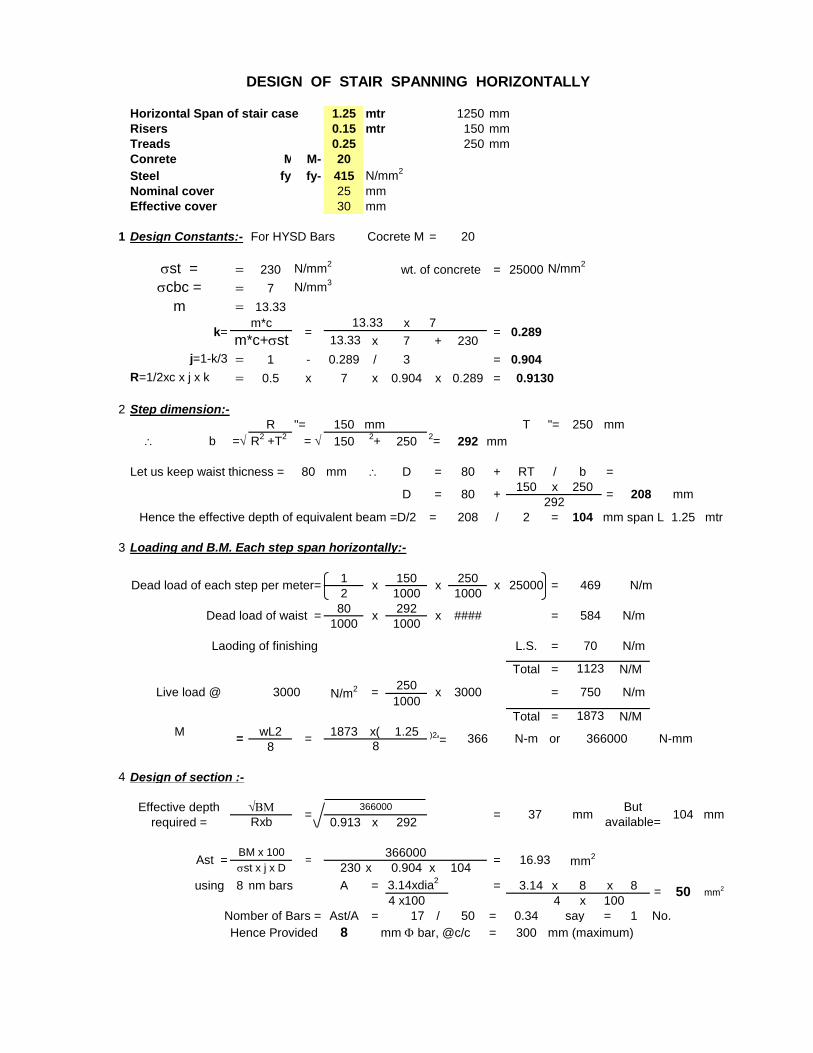
Horizontal Span of stair case 1.25 mtr 1250 mm
Risers 0.15 mtr 150 mm
Treads 0.25 250 mm
Conrete M- M- 20
Steel fy- fy- 415 N/mm2
Nominal cover 25 mm
Effective cover 30 mm
1 Design Constants:- For HYSD Bars = 20
sst = = 230 N/mm2
= 25000 N/mm2
scbc = = 7 N/mm3
m = 13.33
x
13.33 x 7 + 230
j=1-k/3 = 1 - 0.289 / 3 = 0.904
R=1/2xc x j x k = 0.5 x 7 x 0.904 x 0.289 =
2 Step dimension:-
R "= 150 mm T "= 250 mm
\ b = R2 +T
2= 150
2+ 250
2= 292 mm
Let us keep waist thicness = 80 mm \ D = 80 + RT / b =
150 x 250
= 208 / 2 = 104 1.25 mtr
3 Loading and B.M. Each step span horizontally:-
1 150 250
2 1000 1000
80 292
1000 1000
Total = N/M
250
1000
Total = N/M
M wL2 1873 x( 1.25
8
4 Design of section :-
0.913 x 292
230 x 0.904 x 104
using 8mm bars A = 3.14xdia2
= 3.14 x 8 x 8
4 x100 4 x
Nomber of Bars = Ast/A = 17 / 50 = 0.34 say = 1 No.
Hence Provided 8 = 300 mm (maximum)
DESIGN OF STAIR SPANNING HORIZONTALLY
=
Cocrete M
0.9130
0.289m*c+sst
wt. of concrete
k=m*c
=13.33
=D292
= 20880 +
7
N/m
mm
mm span L
Dead load of each step per meter= x x x 25000 = 469
Dead load of waist =
Laoding of finishing L.S. =
N/m
x x #### = 584
= 7503000 N/m2
70 N/m
1123
x
366000= =8
)2'=
Live load @ 3000 N/m
1873
=
N-mm
Effective depth
required == =
Rxb
366000
366 N-m or
mm
Hence the effective depth of equivalent beam =D/2
Ast = = 16.93 mm2
37 mmBut
available=104
= 50 mm2
mm F bar, @c/c
100
BM x 100
sst x j x D=
366000

wall
D
F
Main reinforcement
Section x x
1.25
DESIGN OF STAIR SPANNING HORIZONTALLY
Stringer Beam


DESIGN OF STAIR SPANNING HORIZONTALLY


M-15 M-20 M-25 M-30 M-35 M-40 Grade of concrete
18.67 13.33 10.98 9.33 8.11 7.18
5 7 8.5 10 11.5 13
93.33 93.33 93.33 93.33 93.33 93.33
kc 0.4 0.4 0.4 0.4 0.4 0.4
jc 0.867 0.867 0.867 0.867 0.867 0.867
Rc 0.867 1.214 1.474 1.734 1.994 2.254
Pc (%) 0.714 1 1.214 1.429 1.643 1.857
kc 0.329 0.329 0.329 0.329 0.329 0.329
jc 0.89 0.89 0.89 0.89 0.89 0.89
Rc 0.732 1.025 1.244 1.464 1.684 1.903
Pc (%) 0.433 0.606 0.736 0.866 0.997 1.127
kc 0.289 0.289 0.289 0.289 0.289 0.289
jc 0.904 0.904 0.904 0.904 0.904 0.904
Rc 0.653 0.914 1.11 1.306 1.502 1.698
Pc (%) 0.314 0.44 0.534 0.628 0.722 0.816
kc 0.253 0.253 0.253 0.253 0.253 0.253
jc 0.916 0.916 0.916 0.914 0.916 0.916
Rc 0.579 0.811 0.985 1.159 1.332 1.506
Pc (%) 0.23 0.322 0.391 0.46 0.53 0.599
M-15 M-20 M-25 M-30 M-35 M-40
0.18 0.18 0.19 0.2 0.2 0.2
0.22 0.22 0.23 0.23 0.23 0.23
0.29 0.30 0.31 0.31 0.31 0.32
0.34 0.35 0.36 0.37 0.37 0.38
0.37 0.39 0.40 0.41 0.42 0.42
0.40 0.42 0.44 0.45 0.45 0.46
0.42 0.45 0.46 0.48 0.49 0.49
0.44 0.47 0.49 0.50 0.52 0.52
0.44 0.49 0.51 0.53 0.54 0.55
0.44 0.51 0.53 0.55 0.56 0.57
0.44 0.51 0.55 0.57 0.58 0.60
0.44 0.51 0.56 0.58 0.60 0.62
0.44 0.51 0.57 0.6 0.62 0.63
M-15 M-20 M-25 M-30 M-35 M-40
1.6 1.8 1.9 2.2 2.3 2.5
VALUES OF DESIGN CONSTANTS
Grade of concrete
Modular Ratio
scbc N/mm2
m scbc
(a) sst =
140
N/mm2
(Fe 250)
(b) sst =
190
N/mm2
(c ) sst =
230
N/mm2
(Fe 415)
(d) sst =
275
N/mm2
(Fe 500)
Permissible shear stress Table tv in concrete (IS : 456-2000)
100As Permissible shear stress in concrete tv N/mm2
0.75
1.00
1.25
1.50
bd
< 0.15
0.25
0.50
tc.max
2.753.00 and above
Maximum shear stress tc.max in concrete (IS : 456-2000)
Grade of concrete
1.75
2.00
2.25
2.50

Grade of concrete M-10 M-15 M-20 M-25 M-30 M-35 M-40 M-45
tbd (N / mm2) -- 0.6 0.8 0.9 1 1.1 1.2 1.3
M 15
M 20
M 25
M 30
M 35
M 40
M 45
M 50
(N/mm2) Kg/m2 (N/mm2) Kg/m
2
M 10 3.0 300 2.5 250
M 15 5.0 500 4.0 400
M 20 7.0 700 5.0 500
M 25 8.5 850 6.0 600
M 30 10.0 1000 8.0 800
M 35 11.5 1150 9.0 900
M 40 13.0 1300 10.0 1000
M 45 14.5 1450 11.0 1100
M 50 16.0 1600 12.0 1200 1.4 140
1.2 120
1.3 130
0.9 90
1.0 100
1.1 110
Direct (acc)
-- --
0.6 60
0.8 80
Permissible Bond stress Table tbd in concrete (IS : 456-2000)
Grade of
concrete
Permission stress in compression (N/mm2) Permissible stress in bond (Average) for
plain bars in tention (N/mm2)
(N/mm2) in kg/m2
Bending acbc
Development Length in tension
Grade of
concrete
Plain M.S. Bars H.Y.S.D. Bars
tbd (N / mm2) kd = Ld F tbd (N / mm2) kd = Ld F
0.6 58 0.96 60
0.8 44 1.28 45
1 35 1.6 36
0.9 39 1.44 40
1.1 32 1.76
1.3 27 2.08 28
1.4 25 2.24 26
33
1.2 29 1.92 30
Permissible stress in concrete (IS : 456-2000)

M-50
1.4
Permissible Bond stress Table tbd in concrete (IS : 456-2000)
Development Length in tension