Embed Size (px)
Citation preview
STACKING, PHASING and MATCHING YAGIS
This is a synopsis of a talk presented to the Sydney VHF DX GROUP on Tuesday March 16th 1999 byGordon McDonald VK2ZAB.
QUESTIONS
When the stacking of Yagis is being considered, the questions which usually arise are:1. What are the reasons for stacking anyway?2. Would building a bigger Yagi better suit our needs?3. If we stack, what order of gain increase can we expect?4. Is it better to stack vertically or horizontally?5. How far apart do we stack the Yagis?6. How do we manage the phasing requirements?7. How do we manage the matching requirements?
We will endeavour to answer these questions succinctly.
WHY WE STACK
We stack Yagis in order to increase the gain over that obtainable from one Yagi and/or todecrease the beamwidth. The increase in gain is due to the reduction in beamwidth and it shouldbe noted that the beamwidth is reduced in the plane of stacking only. If we stack vertically thebeamwidth is decreased in the vertical or “H” plane of a horizontally polarised Yagi. Stackinghorizontally results in a narrower beamwidth in the horizontal or “E “plane of a horizontallypolarised Yagi. In some applications, such as interference from or to points off to one side orbelow the main lobe, the reduction in beam width is a more important consideration than the gainincrease. However most people stack to get more gain.
CAN WE USE A BIGGER YAGI INSTEAD?
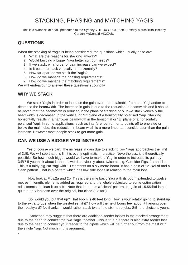
Yes of course we can. The increase in gain due to stacking two Yagis approaches the limitof 3dB. We will see that this limit is overly optimistic in practice. Nevertheless, it is theoreticallypossible. So how much bigger would we have to make a Yagi in order to increase its gain by3dB? If you think about it, the answer is obviously about twice as big. Consider Figs. 1a and 1b.This is a fairly big 2m Yagi with 13 elements on a six metre boom. It has a gain of 12.74dBd and aclean pattern. That is a pattern which has low side lobes in relation to the main lobe.
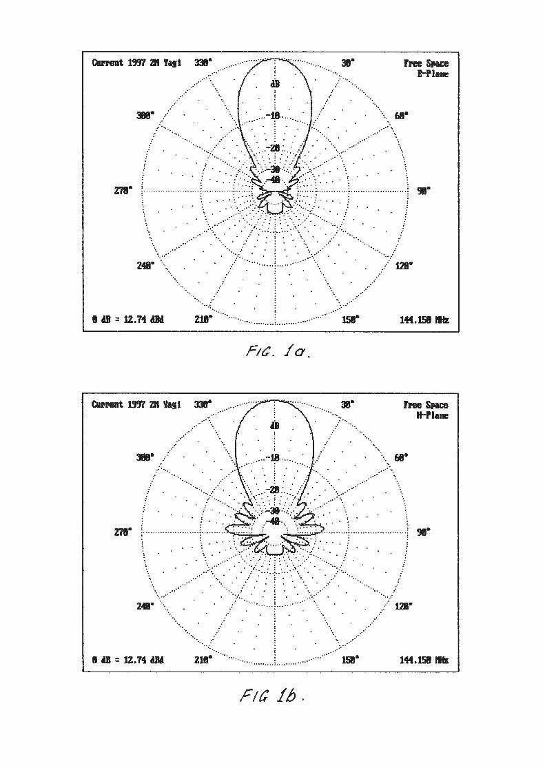
Now look at Figs.2a and 2b. This is the same basic Yagi with its boom extended to twelvemetres in length, elements added as required and the whole subjected to some optimisationadjustments to clean it up a bit. Note that it too has a “clean” pattern. Its gain of 15.55dBd is notquite a 3dB increase over the original, but close (2.81dB).
So, would you put that up? That boom is 40 feet long. How is your rotator going to stand upto the extra torque when the westerlies hit it? How will the neighbours feel about it hanging overtheir backyard? No thanks! I would rather stack two of the six metre jobs. Still, the choice is yours.
Someone may suggest that there are additional feeder losses in the stacked arrangementdue to the need to connect the two Yagis together. This is true but there is also extra feeder lossdue to the need to connect your feeder to the dipole which will be further out from the mast withthe single Yagi. Not much in this argument..
HORIZONTAL OR VERTICAL STACK?
What is your application? Do you think that it would be better to have a wide beamwidth in the “H” plane of your horizontally polarised antenna because you are into MeteorScatter? Stack horizontally. Are you concerned that the power density due to yourtransmission is high in your neighbour’s kitchen and that it would be better if you had anarrow beam in the “H” plane? Stack vertically.
Is there a source of noise twenty degrees off to one side of your most used beamheading? Stack your horizontally polarised antennas horizontally. Are you interested inweak signals and simply want more gain? Stack four Yagis - two up and two across.Again, it’s up to you.
However, remember that horizontal supports near a horizontally polarised Yagi maygive rise to destructive interaction.
HOW FAR APART DO WE STACK?
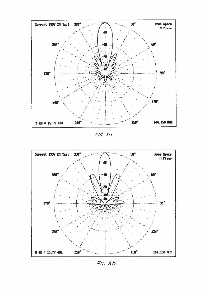
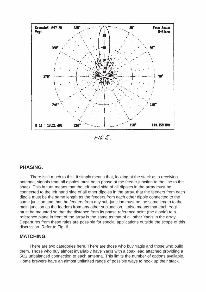
The old rule of thumb was to stack at two thirds of the boom length. This idea waspresumably based on the aim of achieving a 3dB increase in gain over one Yagi. Look atFigs. 3a and 3b. This is the Yagi of Fig. 1 stacked at half and at two thirds the boomlength. Note that at half the boom length large lobes have appeared on each side of themain lobe and 14dB down. These are called “grating” lobes and they are due to thepattern multiplication process so that they appear within the area of the main lobe of asingle Yagi. The gain increase is 2.85dB.
At two thirds the boom length the gain has increased to slightly more than 3dB overone Yagi according to the computer and the grating lobes have increased to less than 8dBdown on the main lobe. If you had intended to reduce interference from or to some pointoff to one side or down from the main lobe this is obviously not going to help much. In factthe pattern has become very “dirty”.
Digressing a bit: This idea of a 3dB increase in gain by stacking two Yagis isexplained in some texts by invoking the concept of “capture area” It is explained that 3dBgain is obtained when the capture areas touch and do not overlap. However this ideadoes not lead to a stacking distance because, although the capture or “effective area” canbe calculated by A = Gain x Wavelength / (4 x Pi), this does not define the shape of thearea. There is no doubt that the capture or “effective” area idea is very useful in someother aspects of antenna engineering. It is dealt with at length by Klaus in his book“Antennas”.
Returning to Fig. 3b. Note that the main beam width is half that of a single Yagi. Thisis where the 3dB gain increase comes from. The beam width in the nonstacked plane (‘E’plane in this case) has not changed.
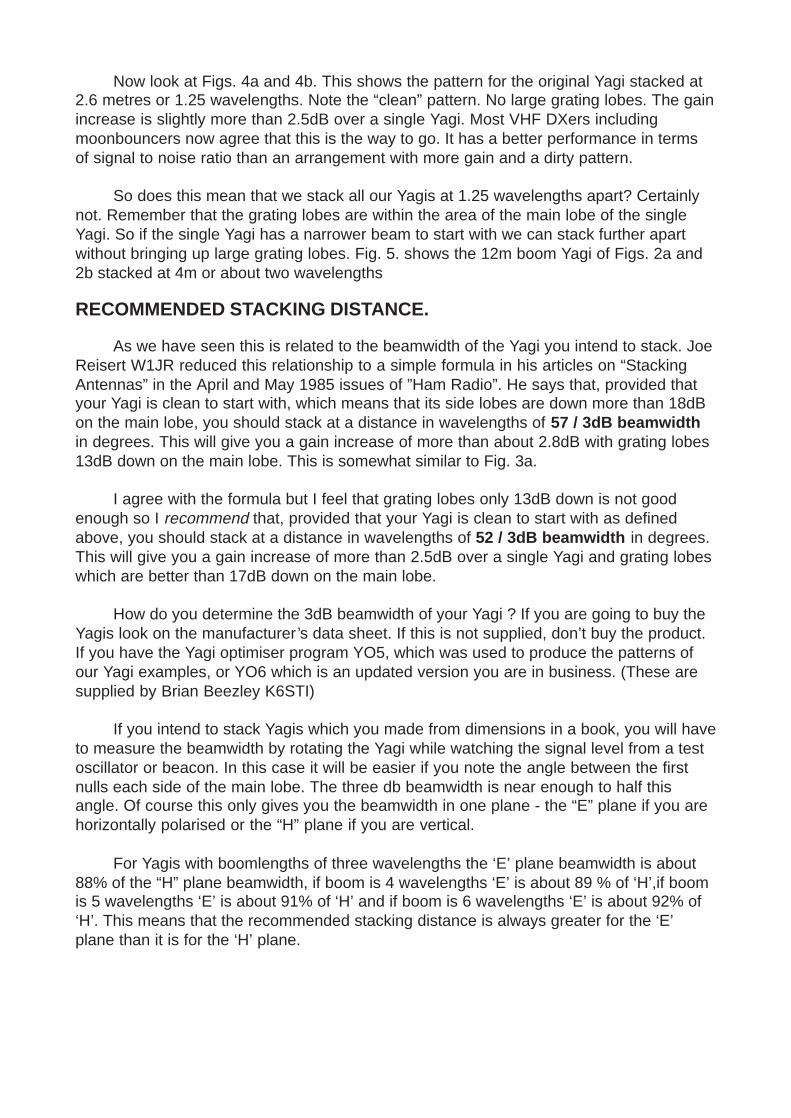
Now look at Figs. 4a and 4b. This shows the pattern for the original Yagi stacked at2.6 metres or 1.25 wavelengths. Note the “clean” pattern. No large grating lobes. The gainincrease is slightly more than 2.5dB over a single Yagi. Most VHF DXers includingmoonbouncers now agree that this is the way to go. It has a better performance in termsof signal to noise ratio than an arrangement with more gain and a dirty pattern.
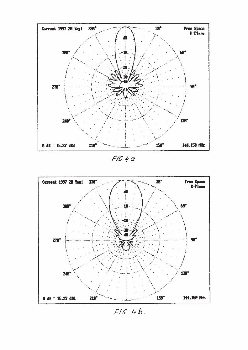
So does this mean that we stack all our Yagis at 1.25 wavelengths apart? Certainlynot. Remember that the grating lobes are within the area of the main lobe of the singleYagi. So if the single Yagi has a narrower beam to start with we can stack further apartwithout bringing up large grating lobes. Fig. 5. shows the 12m boom Yagi of Figs. 2a and2b stacked at 4m or about two wavelengths
RECOMMENDED STACKING DISTANCE.
As we have seen this is related to the beamwidth of the Yagi you intend to stack. JoeReisert W1JR reduced this relationship to a simple formula in his articles on “StackingAntennas” in the April and May 1985 issues of ”Ham Radio”. He says that, provided thatyour Yagi is clean to start with, which means that its side lobes are down more than 18dBon the main lobe, you should stack at a distance in wavelengths of 57 / 3dB beamwidthin degrees. This will give you a gain increase of more than about 2.8dB with grating lobes13dB down on the main lobe. This is somewhat similar to Fig. 3a.
I agree with the formula but I feel that grating lobes only 13dB down is not goodenough so I recommend that, provided that your Yagi is clean to start with as definedabove, you should stack at a distance in wavelengths of 52 / 3dB beamwidth in degrees.This will give you a gain increase of more than 2.5dB over a single Yagi and grating lobeswhich are better than 17dB down on the main lobe.
How do you determine the 3dB beamwidth of your Yagi ? If you are going to buy theYagis look on the manufacturer’s data sheet. If this is not supplied, don’t buy the product.If you have the Yagi optimiser program YO5, which was used to produce the patterns ofour Yagi examples, or YO6 which is an updated version you are in business. (These aresupplied by Brian Beezley K6STI)
If you intend to stack Yagis which you made from dimensions in a book, you will haveto measure the beamwidth by rotating the Yagi while watching the signal level from a testoscillator or beacon. In this case it will be easier if you note the angle between the firstnulls each side of the main lobe. The three db beamwidth is near enough to half thisangle. Of course this only gives you the beamwidth in one plane - the “E” plane if you arehorizontally polarised or the “H” plane if you are vertical.
For Yagis with boomlengths of three wavelengths the ‘E’ plane beamwidth is about88% of the “H” plane beamwidth, if boom is 4 wavelengths ‘E’ is about 89 % of ‘H’,if boomis 5 wavelengths ‘E’ is about 91% of ‘H’ and if boom is 6 wavelengths ‘E’ is about 92% of‘H’. This means that the recommended stacking distance is always greater for the ‘E’plane than it is for the ‘H’ plane.
PHASING.
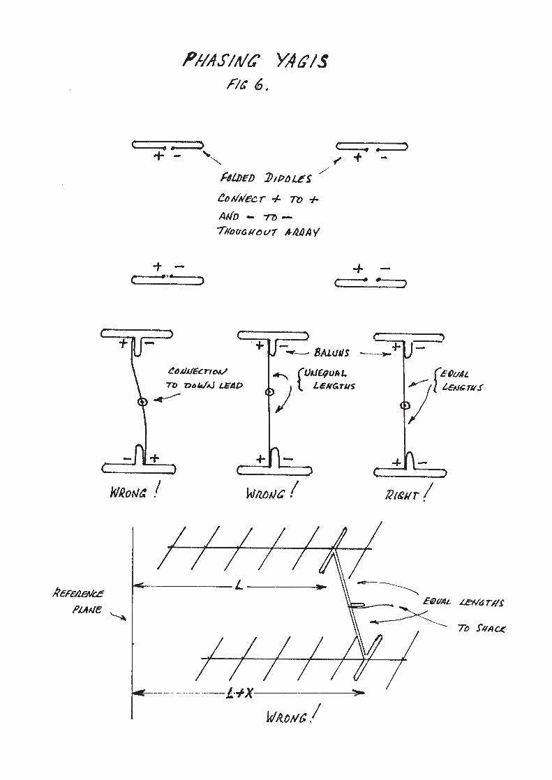
There isn’t much to this. It simply means that, looking at the stack as a receivingantenna, signals from all dipoles must be in phase at the feeder junction to the line to theshack. This in turn means that the left hand side of all dipoles in the array must beconnected to the left hand side of all other dipoles in the array, that the feeders from eachdipole must be the same length as the feeders from each other dipole connected to thesame junction and that the feeders from any sub-junction must be the same length to themain junction as the feeders from any other subjunction. It also means that each Yagimust be mounted so that the distance from its phase reference point (the dipole) to areference plane in front of the array is the same as that of all other Yagis in the array.Departures from these rules are possible for special applications outside the scope of thisdiscussion. Refer to Fig. 6.
MATCHING.
There are two categories here. There are those who buy Yagis and those who buildthem. Those who buy almost invariably have Yagis with a coax lead attached providing a50Ω unbalanced connection to each antenna. This limits the number of options available.Home brewers have an almost unlimited range of possible ways to hook up their stack.
Users of store bought Yagis.
If you are in this category about the only thing you can do is to connect the individualYagis to the common junction by means of quarter wave matching transformers of suchimpedance as to transform the 50Ω of each Yagi to that impedance which is equal to 50xNwhere N is the number of Yagis in the stack. Then, of course, the parallel impedance ofthe lot finishes at 50Ω again to match the line to the shack.
The impedance of the matching transformers is found by the formulaZ = sqrt(50x50N) where sqrt is square root.
For twoYagis this is 70.71Ω, four Yagis 100Ω, six Yagis 122.47Ω and for eight Yagis141.42Ω.
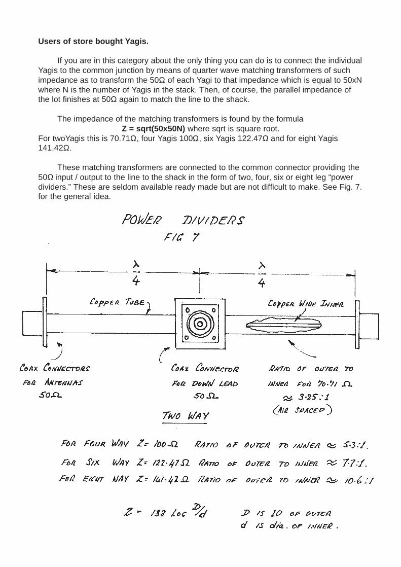
These matching transformers are connected to the common connector providing the50Ω input / output to the line to the shack in the form of two, four, six or eight leg “powerdividers.” These are seldom available ready made but are not difficult to make. See Fig. 7.for the general idea.
The physical parameters of the air space coaxial matching sections are related tothe required impedance by the formula Z = 138 log D/d where ’D’ is the inside diameter ofthe outer conductor and ‘d ‘ is the diameter of the inner conductor.
Home brewers of Yagis.
There is virtually no limit to the options available and so it is impossible to covereverything. We will therefore limit ourselves to a few examples. For a start you couldarrange the connections to your Yagi in the same manner as the store bought examplesabove and use power dividers in the same manner.
However, home brewers can arrange to have any impedance they like at theterminals of their dipoles. This is particularly so if the highly recommended K6STI “YO”programs are available. You simply make a folded dipole of such impedancetransformation ratio as will bring the straight dipole impedance of your Yagi up to theterminal impedance desired. A two conductor dipole with the two legs the same diametermultiplies the impedance by four times. A three conductor, same diameters, dipolemultiplies by nine times and any other ratio may be fabricated using different conductorsizes for a two conductor dipole. A chart providing a straight line approximation ofconductor sizes for different impedance ratios is in the ARRL Antenna Book.
This freedom of choice facilitates the use of open wire interconnecting lines for yourstack. The use of open wire lines is rarely recommended by Hams in the northernhemisphere because they have weather conditions which can cause the build up of iceand snow which changes the impedance and loss of the lines. We don’t. All we have toworry about is water. Provided our lines are made so that the space between conductorsis not closer than about 6mm or 1/4" there will be no problem with water bridging the lines.
Properly made open wire lines have less loss than coax. They may be made ofaluminium tubing with diameters of 9.5mm, 6.35mm or 4.7mm with few spacers so thatthey may also double as boom braces. The loss is related to the spacing which should notexceed about 1/12 of a wavelength. This means that they are practical up to the 23cmband. Practical line impedances are therefore between 300Ω and 150Ω minimum.
In a stack of horizontally polarised Yagis, it is recommended that vertical runs ofinterconnecting lines be of the open wire sort. If this is done with aluminium tubing thelines are referred to as “stacking bars.” The relationship between the line impedance andthe line dimensions is given by Z = 120 arc cosh(D/d) or approximately by Z = 276log(2D/d) where’D’ is the centre to centre spacing and ‘d’ is the diameter of the lines.
Home Brew Stack Examples.
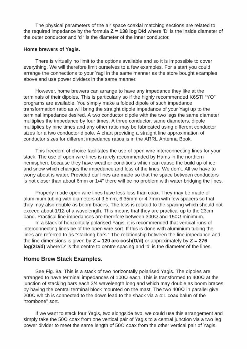
See Fig. 8a. This is a stack of two horizontally polarised Yagis. The dipoles arearranged to have terminal impedances of 100Ω each. This is transformed to 400Ω at thejunction of stacking bars each 3/4 wavelength long and which may double as boom bracesby having the central terminal block mounted on the mast. The two 400Ω in parallel give200Ω which is connected to the down lead to the shack via a 4:1 coax balun of the“trombone” sort.
If we want to stack four Yagis, two alongside two, we could use this arrangement andsimply take the 50Ω coax from one vertical pair of Yagis to a central junction via a two legpower divider to meet the same length of 50Ω coax from the other vertical pair of Yagis.
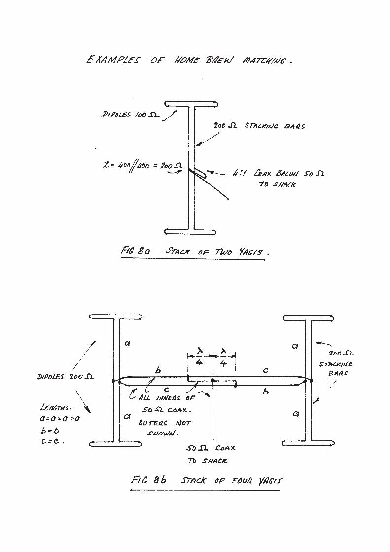
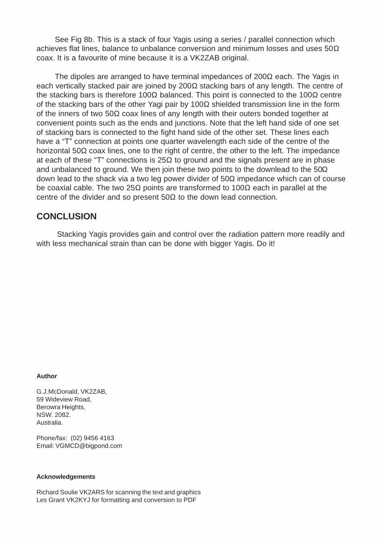
See Fig 8b. This is a stack of four Yagis using a series / parallel connection whichachieves flat lines, balance to unbalance conversion and minimum losses and uses 50Ωcoax. It is a favourite of mine because it is a VK2ZAB original.
The dipoles are arranged to have terminal impedances of 200Ω each. The Yagis ineach vertically stacked pair are joined by 200Ω stacking bars of any length. The centre ofthe stacking bars is therefore 100Ω balanced. This point is connected to the 100Ω centreof the stacking bars of the other Yagi pair by 100Ω shielded transmission line in the formof the inners of two 50Ω coax lines of any length with their outers bonded together atconvenient points such as the ends and junctions. Note that the left hand side of one setof stacking bars is connected to the fight hand side of the other set. These lines eachhave a “T” connection at points one quarter wavelength each side of the centre of thehorizontal 50Ω coax lines, one to the right of centre, the other to the left. The impedanceat each of these “T” connections is 25Ω to ground and the signals present are in phaseand unbalanced to ground. We then join these two points to the downlead to the 50Ωdown lead to the shack via a two leg power divider of 50Ω impedance which can of coursebe coaxial cable. The two 25Ω points are transformed to 100Ω each in parallel at thecentre of the divider and so present 50Ω to the down lead connection.
CONCLUSION
Stacking Yagis provides gain and control over the radiation pattern more readily andwith less mechanical strain than can be done with bigger Yagis. Do it!
Author
G.J.McDonald, VK2ZAB,59 Wideview Road,Berowra Heights,NSW. 2082.Australia.
Phone/fax: (02) 9456 4163Email: [email protected]
Acknowledgements
Richard Soulie VK2ARS for scanning the text and graphicsLes Grant VK2KYJ for formatting and conversion to PDF