Embed Size (px)
Citation preview
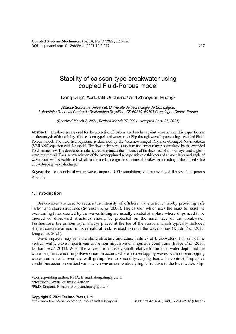
Coupled Systems Mechanics, Vol. 10, No. 3 (2021) 217-228
DOI: https://doi.org/10.12989/csm.2021.10.3.217 217
Copyright © 2021 Techno-Press, Ltd. http://www.techno-press.org/?journal=csm&subpage=8 ISSN: 2234-2184 (Print), 2234-2192 (Online)
Stability of caisson-type breakwater using coupled Fluid-Porous model
Dong Ding, Abdellatif Ouahsinea and Zhaoyuan Huangb
Alliance Sorbonne Université, Université de Technologie de Compiègne, Laboratoire Roberval Centre de Recherches Royallieu, CS 60319, 60203 Compiegne Cedex, France
(Received March 2, 2021, Revised March 27, 2021, Accepted April 21, 2021)
Abstract. Breakwaters are used for the protection of harbors and beaches against wave action. This paper focuses on the analysis of the stability of the caisson-type breakwater under Flip-through wave impacts using a coupled Fluid-Porous model. The fluid hydrodynamic is described by the Volume-averaged Reynolds-Averaged Navier-Stokes (VARANS) equation with k-ε model. The flow in the porous medium and armour layer is simulated by the extended Forchheimer law. The developed model is used to estimate the influence of the thickness of armour layer and angle of wave return wall. Thus, a new relation of the overtopping discharge with the thickness of armour layer and angle of wave return wall is established, which can be used to design the structure of breakwater according to the limited value of overtopping wave discharge.
Keywords: caisson-breakwater; waves impacts; CFD simulation; volume-averaged RANS; fluid-porous
coupling
1. Introduction
Breakwaters are used to reduce the intensity of offshore wave action, thereby providing safe
harbor and shore structures (Sorensen et al. 2000). The caisson which uses the mass to resist the
overturning force exerted by the waves hitting are usually erected at a place where ships need to be
moored or shoreward structures should be protected on the inner face of the breakwater.
Furthermore, the armour layer always placed at the toe of the caisson, which typically included
shaped concrete armour units or natural rock, is used to resist the wave forces (Kaidi et al. 2012,
Ding et al. 2021).
Wave impacts may ruin the shore structure and cause failures of breakwaters. In front of the
vertical walls, wave impacts can cause non-impulsive or impulsive conditions (Bruce et al. 2010,
Darbani et al. 2011). When the waves are relatively small relative to the local water depth and the
wave steepness, a non-impulsive situation occurs, where no overtopping waves occur or overtopping
waves run up and over the wall giving rise to smoothly-varying loads. In contrast, impulsive
conditions occur on vertical walls when waves are relatively higher relative to the local water. Flip-
Corresponding author, Ph.D., E-mail: [email protected] aProfessor, E-mail: [email protected] bPh.D. Student, E-mail: [email protected]
Dong Ding, Abdellatif Ouahsine and Zhaoyuan Huang
Through Impacts (FTI) are typical impulsive wave impacts. Hattori et al. (1994) studied various
types of breaking waves and stressed the influence of the Flip-Through Impact (FTI) which may
cause the overturning of caissons and rear protective structure. Lugni et al. (2006) described three
main steps in the flow evolution of FTI: (1) the wave approaching the wall; (2) the wavefront and
trough are close to each other, resulting in high vertical flow acceleration; and (3) squeezed wave
produces upward-moving jet. The wave overtopping has negative effects on the stability of the
harbor or shore structures on the inner slope of the dike and can result in severe damage. The
structure of armour layer affects the flow of waves. The armour layers are often built of large armour
units and can be considered as a porous medium. Indeed, many recent scientific studies have
considered the porosity parameter to represent different types of armour units in the CFD simulations
(Van Gent 1996). Traditionally, the Darcy law is used to study linear structures and Forchheimer
law is used to investigate non-linear structures for porous medium (Whitaker 1996, Guedda and
Ouahsine 2012, Smaoui et al. 2008).
In this paper, the stability of breakwater under flip-through impacts (FTI) is presented. The fluid
hydrodynamic with the porous medium processes are described by the Volume averaged Reynolds
averaged Navier Stokes (VARANS) equation with k-ε model in which the flow in the porous medium
and armour units is calculated by the extended Forchheimer law. The performance of the stability of
caisson-type breakwater is investigated by considering the thickness of armour layer and angle of
the wave return wall. Thus, a new relation of the overtopping discharge with the thickness of armour
layer and angle of wave return wall is established. The outline of the paper is as follows: in section
2, the governing equations of the fluid and solid coupled model are introduced, the volume-averaged
RANS process is detailed. Section 3 is devoted to presenting the configuration of the numerical
model and validating the inputting fluid model. Section 4 simulates the solution behavior with
various thickness of armour layer and various angles of wave return wall of the caisson. Finally, the
conclusions of the study are drawn in section 5.
2. Mathematical formulation for fluid-porous model
In the present work, a free and open-source CFD toolbox OpenFoam is used to investigate the
flow around the breakwater. In this section, the mathematical formation of two incompressible
phases flow (air and water) in porous medium (armour layer and core), and the process for adjusting
to OpenFoam are introduced.
For the turbulence flow, it can be investigated by RANS-VOF equations. The mass and
momentum conservation are (Du et al. 2018)
0 =U (1)
( ) ( )effPt
+ = − + + +
UUU g U (2)
while the free surface is tracked by
( )1 0ct
+ + − =
U U (3)
where U is the velocity vector, g denotes the gravitational acceleration vector. P is the pseudo-
dynamic pressure, ρ represents the weighted averaged density, and eff t = + , in which μ is the
218
Stability of caisson-type breakwater using coupled Fluid-Porous model
weighted average dynamic viscosity; and the μt is the dynamic turbulence viscosity which is
calculated by k-ε model (Shaheed and Gildeh,2009). The surface tension effect is , where
wateru and airu are the velocity of water and air, respectively, and α is the fluid phase fraction
laying between 0 and 1, where α=0 corresponds to full of air and α=1 corresponds to full of fluid.
The last term (1 ) −cU is an artificial compression term (Higuera et al. 2014, Ji et al. 2014),
where Uc=uwater−uair.
For the porous medium structures, traditionally, Darcy’s law (the first term in Eq. (4) is used to
describe flow in the porous medium for linear problems (Hadzalic et al. 2018), however, when the
non-linear processes take place due to sudden variations in the morphology or of the texture of the
bottom, as is the case here, this last law cannot describe the accurately fluid-porous interaction.
Then, a correction term (the second term) are added in Eq. (4), based on a quadratic velocity, to take
account into this non-linearity. Furthermore, in the present study, an added mass term CA (Hsu et al.
2002) was considered. The reason to consider the added mass is that when a certain amount of water
is accelerating, a certain amount of momentum is required. To accelerate the same volume of water
in a porous medium, additional momentum is required. It is called added mass because excess extra
indicates that a larger volume of fluid must be accelerated (Mendez et al. 2001). The extended
Forchheimer equation can be written as
| | AI A B Ct
= + +
UU U U (4)
where I is the hydraulic pressure gradient and CA is an empirical coefficient associated with the
added mass.
For the coefficients A and B, several different methods can be used to define (Sidiropoulou et al.
2007); here we used the Van Gent’s modification Engelund formulas (Van Gent 1996), which can
be written as
3
1 2 2
50
(1 )A
D
−= (5)
2 2
50
7.5 1(1 )
C
BK D
−= + (6)
where D50 is the mean diameter of the porous material, φ is the porosity of porous medium, and μ1
and μ2 are empirical coefficients related to the linear and nonlinear drag force, respectively. Besides,
due to the unsteadiness of the system, the Keulegan-Carpenter number KC is introduced to describe
additional friction (Sarpkaya 1986).
In order to calculate the porous medium flow for RANS equations, the extended Forchheimer
equation is added to the Eqs. (1)-(2). However, the extension process is not straightforward, the
porosity should be considered; therefore, the hydrodynamic variable U are be averaged by porosity
φ, with respect to the total volume including the fluid volume and the pores. The Volume-Averaged
RANS equations (VARANS) can be written as
0 =U (7)
2
1(1 ) | |( )A effC P A B
n t n n n n n
+ + = − + + + − −
U U UU U U g U (8)
219
Dong Ding, Abdellatif Ouahsine and Zhaoyuan Huang
where U that exists in the interstices of the solid framework of the porous medium, given by
1
fVdV
V = U U (9)
where U is the hydrodynamic velocity with respect to the fluid, V is the total volume, and Vf is the
part of V which is occupied by the fluid.
The Fluid-Porous model is based on the VARANS-VOF method, which describes the fluid flow
with the porous medium processes. The Volume-of-Fluid (VOF) approach is used to describe the
volume fraction of each fluid inside each computational cell (Cui et al. 2020). The MULES
(multidimensional universal limiter for explicit solution) is applied in the OpenFoam, which uses a
limiter factor for the flux of the discrete divergence term to make the fluid phase fraction α laying
between 0 and 1 (Ouahsine et al. 2013). The transport equation can be written as
1 1(1 ) 0( ) ( )
t n n
+ + − =
cU U (10)
In this study, the VARANS equations are numerically implemented in the IHFOAM solver in
which the IHMULES are used to account for the porosity. A new algorithm is called PIMPLE, which
merged by PISO (pressure implicit with the splitting of operators) and SIMPLE (semi-implicit
method for pressure-linked equations) algorithms, are used to obtain the solution of pressure and
velocity fields for solving procedure (Higuera et al. 2014, Khanh et al. 2013, Cai et al. 2017).
3. Simulation model and validation
3.1 Simulation model and boundary conditions
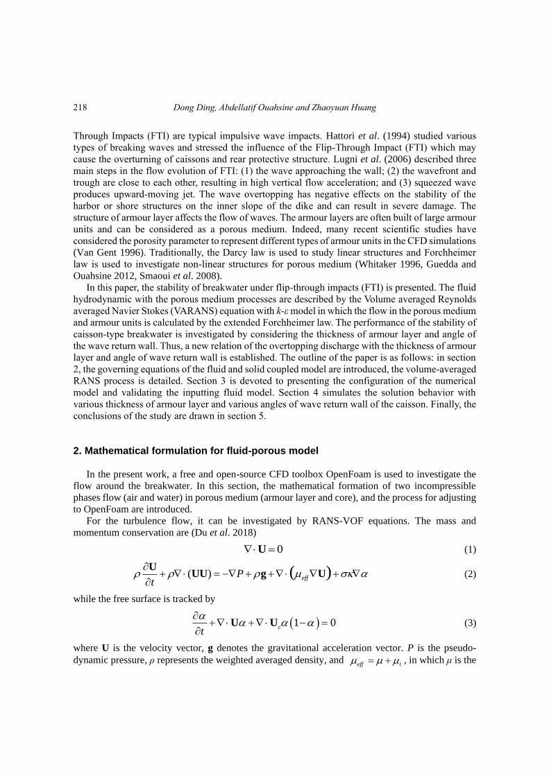
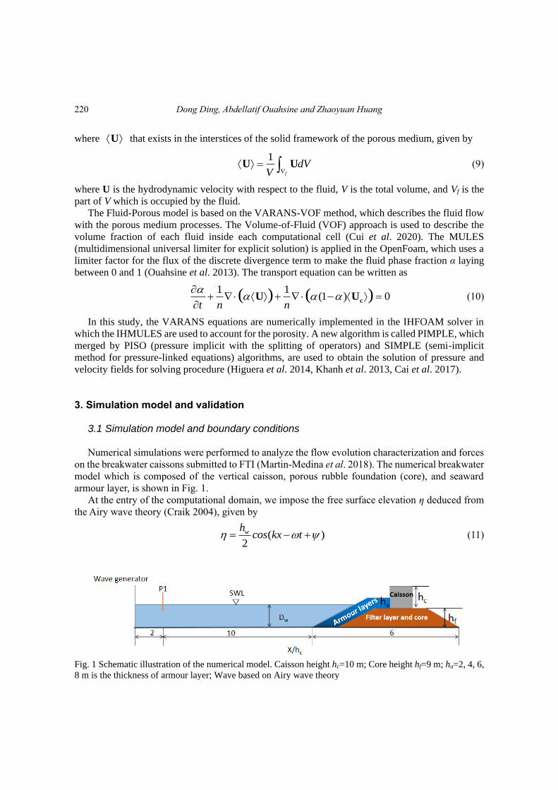
Numerical simulations were performed to analyze the flow evolution characterization and forces
on the breakwater caissons submitted to FTI (Martin-Medina et al. 2018). The numerical breakwater
model which is composed of the vertical caisson, porous rubble foundation (core), and seaward
armour layer, is shown in Fig. 1.
At the entry of the computational domain, we impose the free surface elevation η deduced from
the Airy wave theory (Craik 2004), given by
( )2
whcos kx t = − + (11)
Fig. 1 Schematic illustration of the numerical model. Caisson height hc=10 m; Core height hf=9 m; ha=2, 4, 6,
8 m is the thickness of armour layer; Wave based on Airy wave theory
220
Stability of caisson-type breakwater using coupled Fluid-Porous model
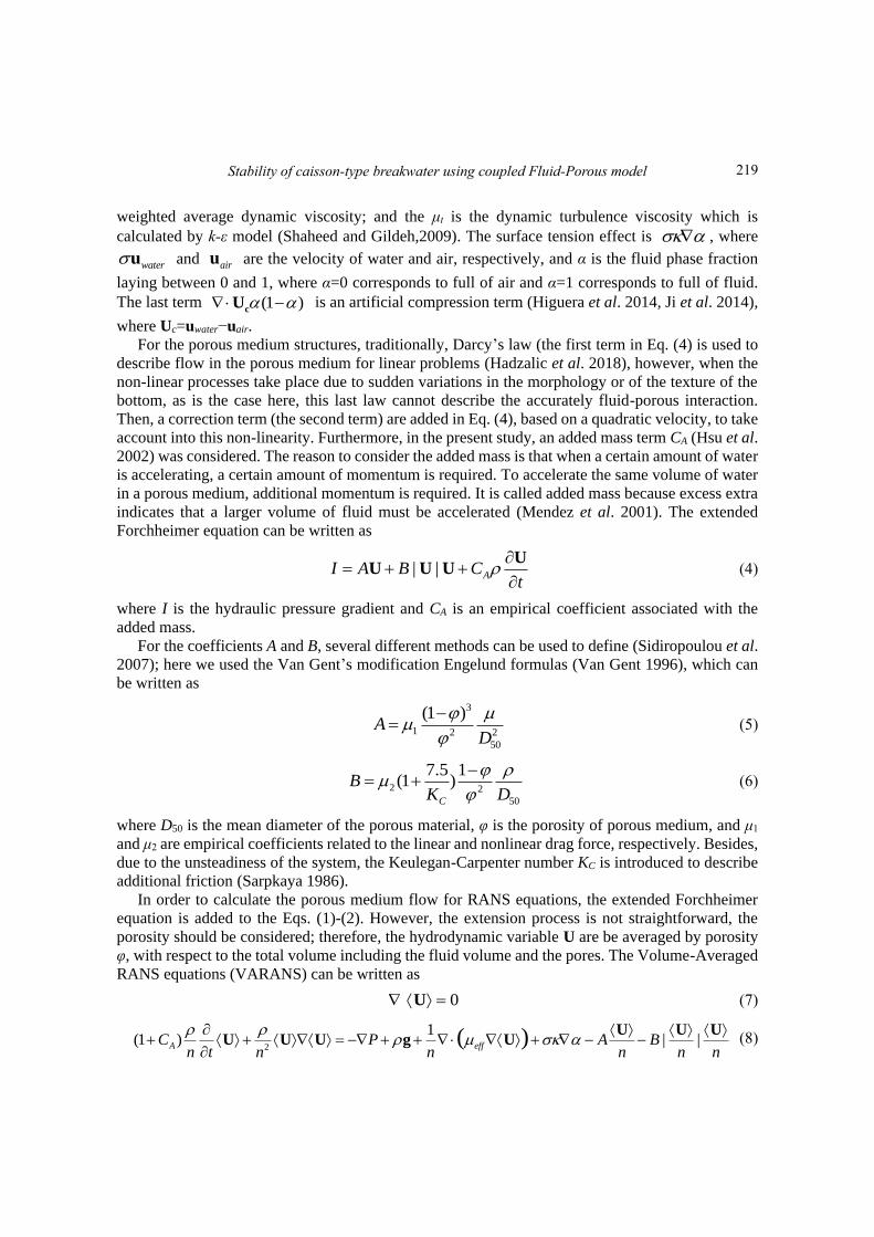
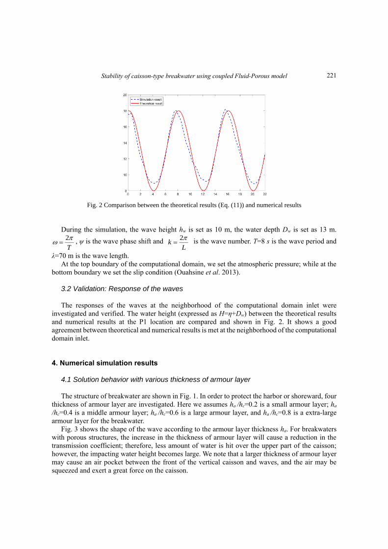
Fig. 2 Comparison between the theoretical results (Eq. (11)) and numerical results
During the simulation, the wave height hw is set as 10 m, the water depth Dw is set as 13 m.
2
T
= , ψ is the wave phase shift and
2k
L
= is the wave number. T=8 s is the wave period and
λ=70 m is the wave length.
At the top boundary of the computational domain, we set the atmospheric pressure; while at the
bottom boundary we set the slip condition (Ouahsine et al. 2013).
3.2 Validation: Response of the waves
The responses of the waves at the neighborhood of the computational domain inlet were
investigated and verified. The water height (expressed as H=η+Dw) between the theoretical results
and numerical results at the P1 location are compared and shown in Fig. 2. It shows a good
agreement between theoretical and numerical results is met at the neighborhood of the computational
domain inlet.
4. Numerical simulation results
4.1 Solution behavior with various thickness of armour layer
The structure of breakwater are shown in Fig. 1. In order to protect the harbor or shoreward, four
thickness of armour layer are investigated. Here we assumes ha /hc=0.2 is a small armour layer; ha
/hc=0.4 is a middle armour layer; ha /hc=0.6 is a large armour layer, and ha /hc=0.8 is a extra-large
armour layer for the breakwater.
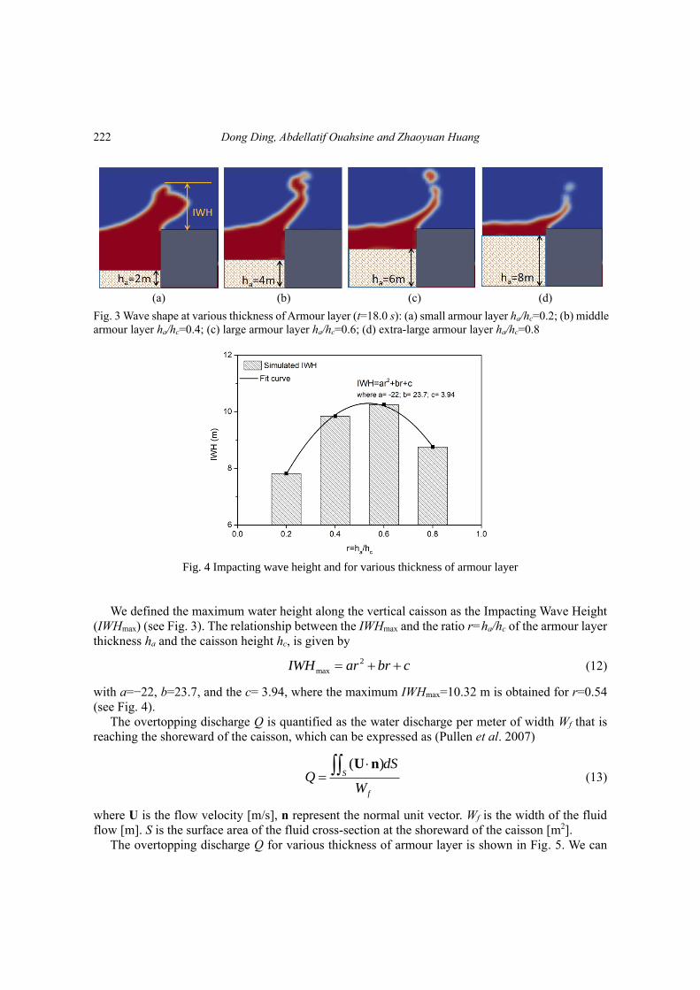
Fig. 3 shows the shape of the wave according to the armour layer thickness ha. For breakwaters
with porous structures, the increase in the thickness of armour layer will cause a reduction in the
transmission coefficient; therefore, less amount of water is hit over the upper part of the caisson;
however, the impacting water height becomes large. We note that a larger thickness of armour layer
may cause an air pocket between the front of the vertical caisson and waves, and the air may be
squeezed and exert a great force on the caisson.
221
Dong Ding, Abdellatif Ouahsine and Zhaoyuan Huang
(a) (b) (c) (d)
Fig. 3 Wave shape at various thickness of Armour layer (t=18.0 s): (a) small armour layer ha/hc=0.2; (b) middle
armour layer ha/hc=0.4; (c) large armour layer ha/hc=0.6; (d) extra-large armour layer ha/hc=0.8
Fig. 4 Impacting wave height and for various thickness of armour layer
We defined the maximum water height along the vertical caisson as the Impacting Wave Height
(IWHmax) (see Fig. 3). The relationship between the IWHmax and the ratio r=ha/hc of the armour layer
thickness ha and the caisson height hc, is given by
2
maxIWH ar br c= + + (12)
with a=−22, b=23.7, and the c= 3.94, where the maximum IWHmax=10.32 m is obtained for r=0.54
(see Fig. 4).
The overtopping discharge Q is quantified as the water discharge per meter of width Wf that is
reaching the shoreward of the caisson, which can be expressed as (Pullen et al. 2007)
( )S
f
dSQ
W
= U n
(13)
where U is the flow velocity [m/s], n represent the normal unit vector. Wf is the width of the fluid
flow [m]. S is the surface area of the fluid cross-section at the shoreward of the caisson [m2].
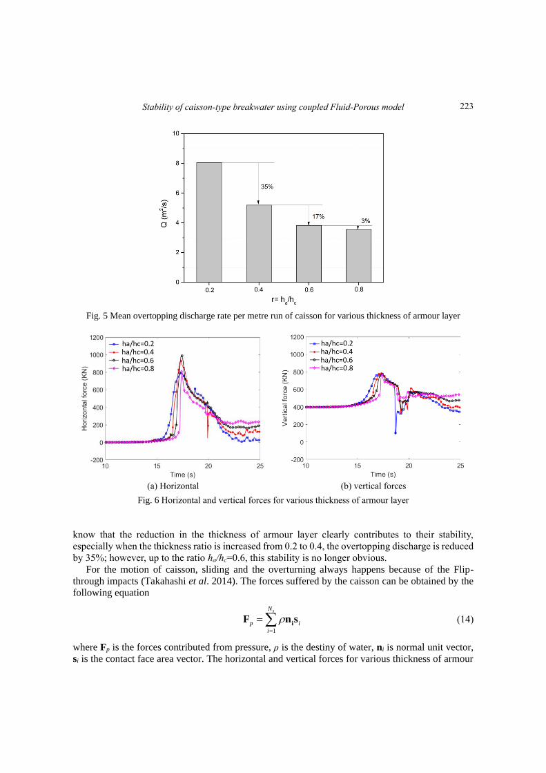
The overtopping discharge Q for various thickness of armour layer is shown in Fig. 5. We can
222
Stability of caisson-type breakwater using coupled Fluid-Porous model
Fig. 5 Mean overtopping discharge rate per metre run of caisson for various thickness of armour layer
(a) Horizontal (b) vertical forces
Fig. 6 Horizontal and vertical forces for various thickness of armour layer
know that the reduction in the thickness of armour layer clearly contributes to their stability,
especially when the thickness ratio is increased from 0.2 to 0.4, the overtopping discharge is reduced
by 35%; however, up to the ratio ha/hc=0.6, this stability is no longer obvious.
For the motion of caisson, sliding and the overturning always happens because of the Flip-
through impacts (Takahashi et al. 2014). The forces suffered by the caisson can be obtained by the
following equation
1
sN
p i
i
=
= iF n s (14)
where Fp is the forces contributed from pressure, ρ is the destiny of water, ni is normal unit vector,
si is the contact face area vector. The horizontal and vertical forces for various thickness of armour
223
Dong Ding, Abdellatif Ouahsine and Zhaoyuan Huang
(a) (b)
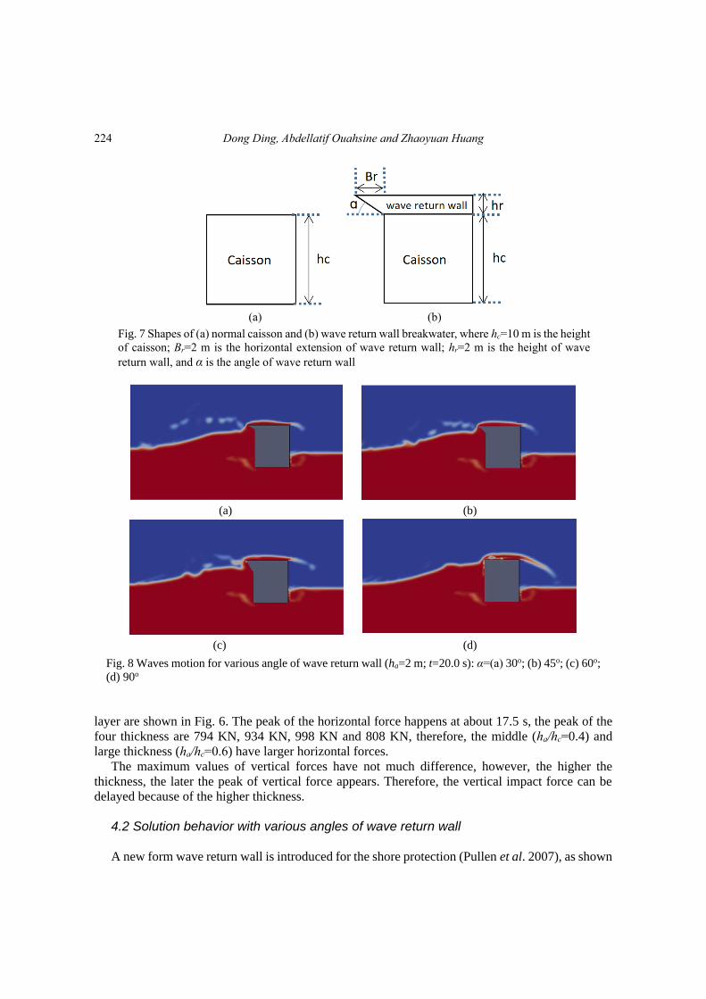
Fig. 7 Shapes of (a) normal caisson and (b) wave return wall breakwater, where hc=10 m is the height
of caisson; Br=2 m is the horizontal extension of wave return wall; hr=2 m is the height of wave
return wall, and α is the angle of wave return wall
(a) (b)
(c) (d)
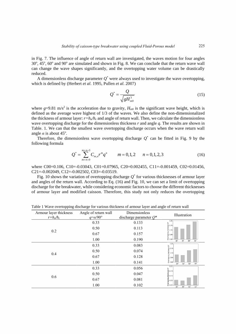
Fig. 8 Waves motion for various angle of wave return wall (ha=2 m; t=20.0 s): α=(a) 30o; (b) 45o; (c) 60o;
(d) 90o
layer are shown in Fig. 6. The peak of the horizontal force happens at about 17.5 s, the peak of the
four thickness are 794 KN, 934 KN, 998 KN and 808 KN, therefore, the middle (ha/hc=0.4) and
large thickness (ha/hc=0.6) have larger horizontal forces.
The maximum values of vertical forces have not much difference, however, the higher the
thickness, the later the peak of vertical force appears. Therefore, the vertical impact force can be
delayed because of the higher thickness.
4.2 Solution behavior with various angles of wave return wall
A new form wave return wall is introduced for the shore protection (Pullen et al. 2007), as shown
224
Stability of caisson-type breakwater using coupled Fluid-Porous model
in Fig. 7. The influence of angle of return wall are investigated, the waves motion for four angles
30o, 45o, 60o and 90o are simulated and shown in Fig. 8. We can conclude that the return wave wall
can change the wave shapes significantly, and the overtopping water volume can be drastically
reduced.
A dimensionless discharge parameter Q* were always used to investigate the wave overtopping,
which is defined by (Herbert et al. 1995, Pullen et al. 2007)
*
3
0m
gH= (15)
where g=9.81 m/s2 is the acceleration due to gravity, Hm0 is the significant wave height, which is
defined as the average wave highest of 1/3 of the waves. We also define the non-dimensionalized
the thickness of armour layer: r=ha/hc and angle of return wall. Then, we calculate the dimensionless
wave overtopping discharge for the dimensionless thickness r and angle q. The results are shown in
Table. 1. We can that the smallest wave overtopping discharge occurs when the wave return wall
angle α is about 45o.
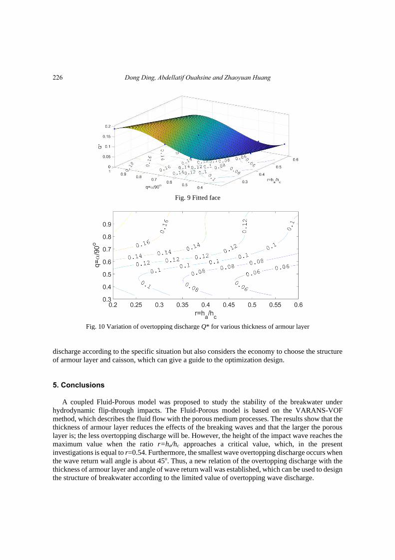
Therefore, the dimensionless wave overtopping discharge Q* can be fitted in Fig. 9 by the
following formula
3*
,
0
0,1,2 0,1,2,3m n
m n
m n
m n
Q C r q m n+ =
+ =
= = = (16)
where C00=0.106, C10=-0.03043, C01=0.07965, C20=0.002455, C11=-0.001459, C02=0.01456,
C21=-0.002049, C12=-0.002502, C03=-0.03519.
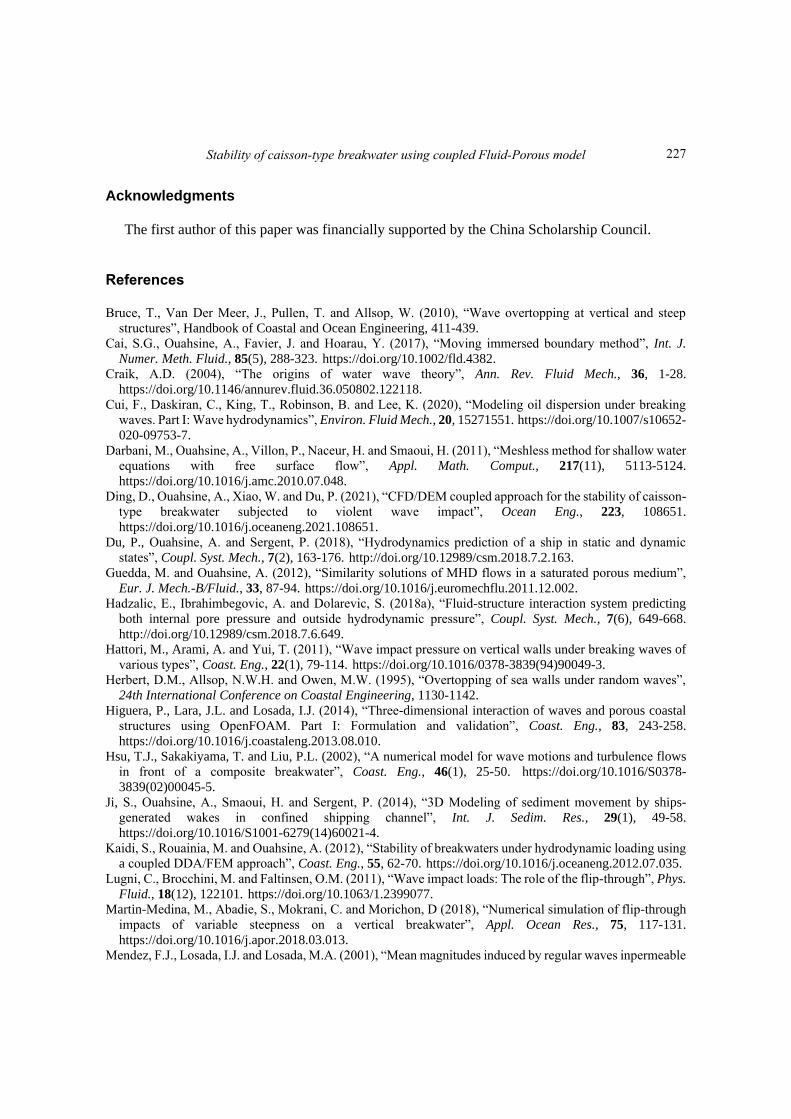
Fig. 10 shows the variation of overtopping discharge Q* for various thicknesses of armour layer
and angles of the return wall. According to Eq. (16) and Fig. 10, we can set a limit of overtopping
discharge for the breakwater, while considering economic factors to choose the different thicknesses
of armour layer and modified caisson. Therefore, this study not only reduces the overtopping
Table 1 Wave overtopping discharge for various thickness of armour layer and angle of return wall
Armour layer thickness
r=ha/hc
Angle of return wall
q=α/90°
Dimensionless
discharge parameter Q* Illustration
0.2
0.33 0.133
0.50 0.113
0.67 0.157
1.00 0.190
0.4
0.33 0.083
0.50 0.074
0.67 0.128
1.00 0.141
0.6
0.33 0.056
0.50 0.047
0.67 0.081
1.00 0.102
225
Dong Ding, Abdellatif Ouahsine and Zhaoyuan Huang
Fig. 9 Fitted face
Fig. 10 Variation of overtopping discharge Q* for various thickness of armour layer
discharge according to the specific situation but also considers the economy to choose the structure
of armour layer and caisson, which can give a guide to the optimization design.
5. Conclusions
A coupled Fluid-Porous model was proposed to study the stability of the breakwater under
hydrodynamic flip-through impacts. The Fluid-Porous model is based on the VARANS-VOF
method, which describes the fluid flow with the porous medium processes. The results show that the
thickness of armour layer reduces the effects of the breaking waves and that the larger the porous
layer is; the less overtopping discharge will be. However, the height of the impact wave reaches the
maximum value when the ratio r=ha/hc approaches a critical value, which, in the present
investigations is equal to r=0.54. Furthermore, the smallest wave overtopping discharge occurs when
the wave return wall angle is about 45o. Thus, a new relation of the overtopping discharge with the
thickness of armour layer and angle of wave return wall was established, which can be used to design
the structure of breakwater according to the limited value of overtopping wave discharge.
226
Stability of caisson-type breakwater using coupled Fluid-Porous model
Acknowledgments
The first author of this paper was financially supported by the China Scholarship Council.
References Bruce, T., Van Der Meer, J., Pullen, T. and Allsop, W. (2010), “Wave overtopping at vertical and steep
structures”, Handbook of Coastal and Ocean Engineering, 411-439.
Cai, S.G., Ouahsine, A., Favier, J. and Hoarau, Y. (2017), “Moving immersed boundary method”, Int. J.
Numer. Meth. Fluid., 85(5), 288-323. https://doi.org/10.1002/fld.4382.
Craik, A.D. (2004), “The origins of water wave theory”, Ann. Rev. Fluid Mech., 36, 1-28. https://doi.org/10.1146/annurev.fluid.36.050802.122118.
Cui, F., Daskiran, C., King, T., Robinson, B. and Lee, K. (2020), “Modeling oil dispersion under breaking
waves. Part I: Wave hydrodynamics”, Environ. Fluid Mech., 20, 15271551. https://doi.org/10.1007/s10652-
020-09753-7.
Darbani, M., Ouahsine, A., Villon, P., Naceur, H. and Smaoui, H. (2011), “Meshless method for shallow water
equations with free surface flow”, Appl. Math. Comput., 217(11), 5113-5124. https://doi.org/10.1016/j.amc.2010.07.048.
Ding, D., Ouahsine, A., Xiao, W. and Du, P. (2021), “CFD/DEM coupled approach for the stability of caisson-
type breakwater subjected to violent wave impact”, Ocean Eng., 223, 108651. https://doi.org/10.1016/j.oceaneng.2021.108651.
Du, P., Ouahsine, A. and Sergent, P. (2018), “Hydrodynamics prediction of a ship in static and dynamic
states”, Coupl. Syst. Mech., 7(2), 163-176. http://doi.org/10.12989/csm.2018.7.2.163.
Guedda, M. and Ouahsine, A. (2012), “Similarity solutions of MHD flows in a saturated porous medium”,
Eur. J. Mech.-B/Fluid., 33, 87-94. https://doi.org/10.1016/j.euromechflu.2011.12.002.
Hadzalic, E., Ibrahimbegovic, A. and Dolarevic, S. (2018a), “Fluid-structure interaction system predicting
both internal pore pressure and outside hydrodynamic pressure”, Coupl. Syst. Mech., 7(6), 649-668. http://doi.org/10.12989/csm.2018.7.6.649.
Hattori, M., Arami, A. and Yui, T. (2011), “Wave impact pressure on vertical walls under breaking waves of
various types”, Coast. Eng., 22(1), 79-114. https://doi.org/10.1016/0378-3839(94)90049-3.
Herbert, D.M., Allsop, N.W.H. and Owen, M.W. (1995), “Overtopping of sea walls under random waves”,
24th International Conference on Coastal Engineering, 1130-1142.
Higuera, P., Lara, J.L. and Losada, I.J. (2014), “Three-dimensional interaction of waves and porous coastal
structures using OpenFOAM. Part I: Formulation and validation”, Coast. Eng., 83, 243-258. https://doi.org/10.1016/j.coastaleng.2013.08.010.
Hsu, T.J., Sakakiyama, T. and Liu, P.L. (2002), “A numerical model for wave motions and turbulence flows
in front of a composite breakwater”, Coast. Eng., 46(1), 25-50. https://doi.org/10.1016/S0378-
3839(02)00045-5.
Ji, S., Ouahsine, A., Smaoui, H. and Sergent, P. (2014), “3D Modeling of sediment movement by ships-
generated wakes in confined shipping channel”, Int. J. Sedim. Res., 29(1), 49-58. https://doi.org/10.1016/S1001-6279(14)60021-4.
Kaidi, S., Rouainia, M. and Ouahsine, A. (2012), “Stability of breakwaters under hydrodynamic loading using
a coupled DDA/FEM approach”, Coast. Eng., 55, 62-70. https://doi.org/10.1016/j.oceaneng.2012.07.035.
Lugni, C., Brocchini, M. and Faltinsen, O.M. (2011), “Wave impact loads: The role of the flip-through”, Phys.
Fluid., 18(12), 122101. https://doi.org/10.1063/1.2399077.
Martin-Medina, M., Abadie, S., Mokrani, C. and Morichon, D (2018), “Numerical simulation of flip-through
impacts of variable steepness on a vertical breakwater”, Appl. Ocean Res., 75, 117-131. https://doi.org/10.1016/j.apor.2018.03.013.
Mendez, F.J., Losada, I.J. and Losada, M.A. (2001), “Mean magnitudes induced by regular waves inpermeable
227
Dong Ding, Abdellatif Ouahsine and Zhaoyuan Huang
submerged breakwaters”, J. Waterw. Port Coast. Ocean Eng., 127(1), 7-15.
Ouahsine, A., Smaoui, H., Meftah, K., Sergent, P. and Sabatier, F. (2013), “Numerical study of coastal sandbar
migration, by hydro-morphodynamical coupling”, Environ. Fluid Mech., 13(2), 169-187. https://doi.org/10.1007/s10652-012-9252-5.
Pullen, T., Allsop, N.W.H., Bruce, T., Kortenhaus, A., Schüttrumpf, H. and Van der Meer, J.W. (2007),
EurOtop Wave Overtopping of Sea Defences and Related Structures: Assessment Manual.
Sarpkaya, T. (1986), “Force on a circular cylinder in viscous oscillatory flow at low Keulegan-Carpenter
numbers”, J. Fluid Mech., 165, 61-71.
Shaheed, R., Mohammadian, A. and Gildeh, H.K. (2019), “A comparison of standard k-ε and realizable k-ω
turbulence models in curved and confluent channels”, Environ. Fluid Mech., 19(2), 543-568. ttps://doi.org/10.1007/s10652-018-9637-1.
Sidiropoulou, M.G., Moutsopoulos, K.N. and Tsihrintzis, V.A. (2007), “Determination of Forchheimer
equation coecients a and b”, Hydrol. Proc., 21(4), 534-554. https://doi.org/10.1002/hyp.6264.
Smaoui, H., Zouhri, L. and Ouahsine, A. (2008), “Flux-limiting techniques for simulation of pollutant
transport in porous media: Application to groundwater management”, Math. Comput. Model., 47(2), 47-59. https://doi.org/10.1016/j.mcm.2007.02.006.
Sorensen, J.D and Burcharth, H.F. (2000), “Reliability analysis of geotechnical failure modes for vertical wall
breakwaters”, Comput. Geotech., 26(3), 225{246.
Takahashi, H., Sassa, S., Morikawa, Y., Takano, D. and Maruyama, K. (2014), “Stability of caisson-type
breakwater foundation under tsunami-induced seepage”, Soil. Found., 54(4), 789-805. https://doi.org/10.1016/j.sandf.2014.07.002.
Tran Khanh, T., Ouahsine, A., Naceur, H. and ELWassifi, K. (2013), “Assessment of ship manoeuvrability
by using a coupling between a nonlinear transient manoeuvring model and mathematical programming
techniques”, J. Hydrodyn., 25(5), 788-804. https://doi.org/10.1016/S1001-6058(13)60426-6.
Van Gent, M.R.A. (1996), “Wave interaction with permeable coastal structures”, Int. J. Rock Mech. Min. Sci.
Geomech. Abs., 6(33), 277A.
Whitaker, S. (1996), “The Forchheimer equation: a theoretical development”, Tran. Porous Media, 25(1), 27-
61. https://doi.org/10.1007/BF00141261.
228