Embed Size (px)
Citation preview
IJREAT International Journal of Research in Engineering & Advanced Technology, Volume 4, Issue 4, Aug - Sept, 2016 ISSN: 2320 – 8791 (Impact Factor: 2.317)
www.ijreat.org
www.ijreat.org Published by: PIONEER RESEARCH & DEVELOPMENT GROUP (www.prdg.org) 94
Stability Monitoring & Control On The Grid Prototype
Saurabh Jain1, Dr Anand Khare2
1Associate Professor, Swami Vivekanand College of Engineering, Indore and
Research Scholar, Bhagwant University, Ajmer, Rajasthan
2 Research Director, The MRPC Company, Hyderabad and
Research Supervisor, Bhagwant University, Ajmer Rajasthan
ABSTRACT
This paper discusses about the studies made
on the 3-Phase Grid Prototype to simulate
disturbances and regain stability. Few
experiments are analyzed to understand the
difficulties faced while achieving stability. A
hardware model was constructed “3-Phase
Grid Prototype” with provision for
simulating generator, trans-mission Lines
and loads for Dynamic stability studies.
Key words: FACTS, UPFC, SCADA,
Stability, Dynamic, Prototype, Simulation
INTRODUCTION
This research paper presents the study and
analysis made on the hardware model: “3-
Phase Grid Prototype”.
This model simulates 400 kV transmission
line system to study the dynamic stability
and difficulties arising in achieving the
stability during power flow and fault
conditions in a interconnected grid system.
This model has capacity of 3 generators, 3
transmission lines, 3 loads, SCADA
automation and FACTS device – UPFC.
[1] Saurabh Jain, Dr Anand Khare et.al,
(2016) in their paper have described about
the construction of 3-Phase Grid Prototype
hardware model on which stability studies
can be analyzed while simulating conditions
of disturbances during power flow and fault
analysis in an interconnected grid system
and regain stability with external devices to
control and monitor the system with use of
SCADA and UPFC.
IJREAT International Journal of Research in Engineering & Advanced Technology, Volume 4, Issue 4, Aug - Sept, 2016 ISSN: 2320 – 8791 (Impact Factor: 2.317)
www.ijreat.org
www.ijreat.org Published by: PIONEER RESEARCH & DEVELOPMENT GROUP (www.prdg.org) 95
CONFIGURATION OF 3 PHASE GRID
PROTOTYPE
a. Generators (G)
The generator panel has two 3-Phase
generators of 2 KVA capacity each and one
2 KVA Solar Renewable energy source 415
Volts, three phase motor-generator sets are
provided with motor drives, reverse power
relay, short circuit relay with circuit
breakers for their protection. Three phase
digital Multi Function Meters (MFM)
displays voltage, current, power factor,
frequency, active and reactive power. The
multifunction meters also have RS285 port
for data communication with computer
software. The generator alternator output is
stepped down by transformer to100 volts
The Motor-Alternator Control Panel
The two 3 Phase / 2 KVA motor alternator
sets (Generator supply 1 and 2) have a
separate Control Panel with digital meters
and variac arrangement to control speed and
excitation of motor-generator and another
variac for varying the voltage.
Solar Renewable Energy Source: 3-Phase
2kVA with sinusoidal output.
b. Loads (L)
The passive load comprises of Resistive /
Inductive / Capacitive banks and protection
devices.
c. Transmission Lines (TL)
The TL has pi section divided in three
sections of 200 km each giving a total length
of 600 km (see table no 1). TL also has the
necessary protection devices - MCB / over
current relay. The TL is provided with the
digital MFM with RS285 Port. The TL
configuration is in the form of a pi-section
with RLC values. One MFM is provided at
the Sending end of the TL and another at the
Receiving end of each section.
d. SCADA Automation
Supervisory Control and Data Acquisition
monitors and controls various components
on the hardware model – 3-Phase Grid
Prototype.
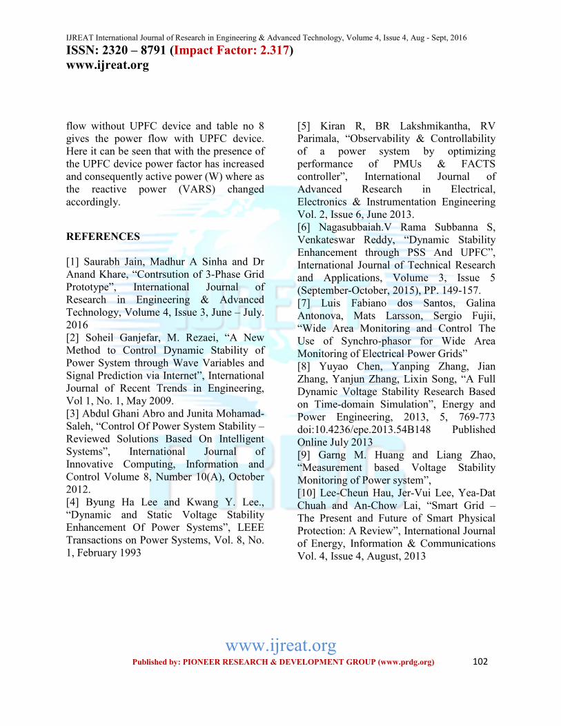
e. UPFC device
The shunt and series transformer with the
AC to DC and DC to AC arrangement
allows better utilization of existing
transmission system, increases transmission
system reliability & also increases grid
stability.
REVIEW OF LITERATURE
[2] Soheil Ganjefar, et.al, (2009) have
discussed about stability of power system
which includes 4 major parts, permanent
stability, transient stability, voltage stability
and dynamic stability (small signal). They
state that one of the most important parts of
power system stability is dynamic stability.
Controlling devices to improve dynamic
IJREAT International Journal of Research in Engineering & Advanced Technology, Volume 4, Issue 4, Aug - Sept, 2016 ISSN: 2320 – 8791 (Impact Factor: 2.317)
www.ijreat.org
www.ijreat.org Published by: PIONEER RESEARCH & DEVELOPMENT GROUP (www.prdg.org) 96
stability of power systems are called power
system stabilizers (PSS). Changes and
expansions of the network may cause
movement of stabilizers. In this paper
internet has been used for a fast and easy-
accessible network. Simulation in this paper
has been done by MATLAB software. They
have concluded the advantages of their
method which includes: reduction of number
of network stabilizers, controlling dynamic
stability of the whole system in one point,
increasing flexibility of network which
resulted in efficiency by this method.
[3] Abdul Ghani Abro, et.al, (2012) in their
paper have discussed about the deregulation
and growth of the power industry, power
systems elements which are forced to
operate very near to their maximum capacity
and how the system becomes vulnerable.
They have elaborated about controlled
operations in power systems which is very
critical and important in order to achieve
stable power system. Therefore,
implementing fast, efficient and reliable
control algorithms, robust and efficient
power system controllers with intelligent
systems; neural networks, fuzzy logic and
bio-inspired optimization algorithms is
necessary. Their paper reviews intelligent
controllers at the generator end of power
systems and discussed further about the
performance of power system enhancement
by using local-agents and wide area control
simultaneously. They concluded that Wide-
area-control alone does not enhance power
system performance. Their results state that
neuro-controller has performed better than
conventional controller as it reduces
computational burden and has simpler
control loop.
[4] Byung Ha Lee, et.al, (1993) in their
paper have discussed about the static voltage
stability and the dynamic voltage stability.
For an accurate analysis of the dynamic
voltage stability, they have built a model
which includes excitation systems, tap-
changers, capacitors and power system
stabilizers in addition to network equations.
This model is developed to determine
optimal control parameters for dynamic
voltage stability enhancement, control of
static voltage stability, for which shunt
capacitor and tap-changer were used. Their
results and findings show that the control of
the shunt capacitor and the tap-changer can
increase the stability margin for static
voltage stability and the increase of the
stability margin improves the overall voltage
of the power system, preventing a severe
voltage decline.
[5] Kiran R, et.al, (2103) in their paper have
discussed about optimal location for PMUs
and FACTS devices, to have an efficient
monetary and control system. This paper
presents a simple and effective method for
optimal placement of PMUs and FACTS
devices. A voltage stability based weak bus
screening method has been utilized to select
critical buses for determining power system
stability. An algorithm is proposed for the
PMU placement to determine optimal
locations for the system observability. This
IJREAT International Journal of Research in Engineering & Advanced Technology, Volume 4, Issue 4, Aug - Sept, 2016 ISSN: 2320 – 8791 (Impact Factor: 2.317)
www.ijreat.org
www.ijreat.org Published by: PIONEER RESEARCH & DEVELOPMENT GROUP (www.prdg.org) 97
paper deals with simulation of IEEE 14-bus
power system using STATCOM & UPFC to
improve the power quality. They state that
UPFC is capable of improving transient
stability in a power system; the real and
reactive powers can be easily controlled.
The simulation results of eight bus system
with and without STATCOM & UPFC have
been analyzed. Their simulation studies
indicate the usefulness of STATCOM &
UPFC to mitigate the voltage sag.
Transmission capability of the existing
transmission line has improved with the
presence of UPFC.
[6] Nagasubbaiah V, et.al, (2015) in their
paper have proposed PSO based PSS. The
authors conclude that construction and
implementation of proposed controller is
fairly easy and economical, which can be
useful in real world power system. The
proposed controller has been tested on a 3
machine 9 bus power system in comparison
with the GA based PSS controllers under
different fault conditions.
[7] Galina Antonova, et.al, in their paper
describe the latest developments in the wide
area monitoring of power grids IEEEC37
118.1-2011 synchrophasor measurement.
They have outlined fundamentals of
synchro-phasor systems, and focused on the
latest techno advances and applications
utilized in the existing and emerging power
grids. They state that introduction of
synchro-phasor measurements as well as
advances in communications and processing
power makes it technically feasible to
monitor the stability of the power system
on-line in real system.
[8] Yuyao Chen, et.al, (2013) in their paper
have discussed about the dynamic stability
and to practically analyze the stability of
voltage. Time-domain simulation is opted as
it is an important measure in research of
complex power grid. In their paper they
have used full dynamic simulation program
based on time-domain simulation in
dynamic voltage stability research, raise
methods and steps to figure out dynamic
voltage stability in both with and without
consideration of over-excitation limitation.
Their results conclude that the effect and
influence of generator over-excitation
limitation in full dynamic voltage stability
research.
[9] Garng M, et.al, in their paper have
proposed a method for online monitoring of
a power system, which aims at detection of
the voltage instability. They state the
advantages of the method: Kirchhoff-Law
by which simple numerical calculation and
strong adaptation in steady state and
transient process the instability can be
predicted through the indicators it would be
easy to find the vulnerable area in a system.
A real time measurement based voltage
stability indicator for monitoring of the
power systems is presented in their paper.
They have concluded that:
- The indicator can predict the voltage
stability problem correctly and properly by
using both steady-state data as well as
dynamic data.
IJREAT International Journal of Research in Engineering & Advanced Technology, Volume 4, Issue 4, Aug - Sept, 2016 ISSN: 2320 – 8791 (Impact Factor: 2.317)
www.ijreat.org
www.ijreat.org Published by: PIONEER RESEARCH & DEVELOPMENT GROUP (www.prdg.org) 98
- The indicator can be used for both static
and dynamic voltage problems.
- It is very easy to locate the vulnerable
locations of the system.
- The indicator can correctly predict the
collapse point of the system.
[10] Lee Cheun, et.al, (2013) in their paper
have discussed about smart grid which
provides bi-directional flow of electricity
and information, with improving the power
grid reliability, security, and efficiency of
electrical system from generation to
transmission and distribution. Their paper
reviews the current state-of-art technology
and focuses on the system reliability
analysis and failure in protection
mechanism.
[11] Alok Kumar, et.al, in their paper have
discussed about the benefits of utilizing
FACTS devices with the purpose of
improving the operation of an electrical
power system. Performance of different
FACTS controllers has also been discussed.
The essential features of FACTS controllers
and their potential to improve system
stability for effective & economic operation
of the power system has been highlighted.
[12] Mudassir A Maniar, et.al, (2013) in
their paper have presented analytical method
to find optimal location of PMU to make
power system observable. This Optimal
PMU Placement (OPP) is optimization
problem which has been solved using BILP
(Binary Integer Linear Programming). The
analytical method has been coded in the
MATLAB and applied to different IEEE test
systems up to 118 buses.
[13] J Wadhawan, et.al, (2012) in their paper
have proposed a model of unified power
flow controller (UPFC) in a single machine
six bus system.
The solution is the use of FACTS. Their
model consists of a simple voltage source
whose magnitude and angle depends on the
UPFC control parameter. They have
concluded with their results and
observations that in case of power flow
control mode for first three faults i.e. LG,
LL, LLG, active power is increased with
same reactive power with the use of UPFC.
For voltage injection mode:
i. Bypass breaker closed P=584.2MW,
Q = 27 MVAR ii. Bypass breaker opened,
the magnitude of the injected series voltage
is increased. Their simulation results show
the effectiveness of UPFC to control the real
and reactive power.
[14] Ankita Pail, et.al, (2015) in their paper
have discussed about the architecture of
power system automation and its usage in
the industry along with its future scope and
technologies. They state that the use of
Ethernet will involve communications
within substations and control room. In
future the control systems will supervise the
systems, rather than controlling it.
Computers will be at the power plant but the
operator will be somewhere else. Data will
be available through portals to the outside
world with the aim to optimize process and
operation costs to reduce.
IJREAT International Journal of Research in Engineering & Advanced Technology, Volume 4, Issue 4, Aug - Sept, 2016 ISSN: 2320 – 8791 (Impact Factor: 2.317)
www.ijreat.org
www.ijreat.org Published by: PIONEER RESEARCH & DEVELOPMENT GROUP (www.prdg.org) 99
[15] Manoj Chaudhry, et.al, (2014) in their
paper have highlighted the advantages of
using FACTS devices for the purpose of
improving the operation of an electrical
power system. Comparison on the basis of
performance of different FACTS controllers
has been discussed. Voltage profile
improvement and stability enhancement of
power system using UPFC is presented in
the paper. SIMULINK models of five bus
test system and UPFC were developed. The
test system has been analyzed with &
without incorporating UPFC. Two case
studies were taken up, where faults occurred
at two buses i.e. 4th and 5th. For both cases
the faults were created at 1 second and
cleared at 1.5 second. It has been observed
that the oscillations of rotor angle in
generator, which is near to fault, increased
and lost synchronism. In other generator
rotor angle sustained for 30 seconds.
Further, UPFC has been incorporated in test
system at line 1- 4 and analyzed for the fault
conditions.
[16] Neha Gaur, et.al, (2012) in their paper
have discussed about the present and past
status of the research and development
activities in the area of electric power
distribution automation both in developed as
well as in developing countries. The
information given in this paper is useful to
electric power distribution utilities and
academicians involved in research and
development activities in the area of power
distribution automation.
[17] Akwukwaegbu, et.al, (2013) in their
paper have presented an analysis of reactive
power control and voltage stability in power
systems. They describe a new model used to
enhance voltage stability and expose several
key issues that had remained as research
challenges in this area. The steady state
voltage and reactive power control in
distribution systems can be properly
controlled by coordinating the available
voltage and reactive power control
equipment, such as on-load tap-changers,
substation shunt capacitors and feeder shunt
capacitors. In their paper, several
representative techniques of reactive power
and voltage, VAR control are reviewed.
Their advantages and disadvantages are
analyzed.
[18] B. Vijay Kumar, et.al, (2016) in their
paper have proposed a hybrid method for
improving the dynamic stability of the
power system using UPFC. Their proposed
method is implemented in the
MATLAB/SIMULINK platform with IEEE
30 and IEEE 14 standard bench mark
system.
Their paper describes about the hybrid
technique based improvement on the
dynamic stability of the power system. In
their technique, the maximum power loss
bus is referred as the optimum location of
the UPFC, which has been obtained by the
bat inspired algorithm. They concluded with
a comparison result which is effective
technique to maintain the dynamic stability
of the power system.
IJREAT International Journal of Research in Engineering & Advanced Technology, Volume 4, Issue 4, Aug - Sept, 2016 ISSN: 2320 – 8791 (Impact Factor: 2.317)
www.ijreat.org
www.ijreat.org Published by: PIONEER RESEARCH & DEVELOPMENT GROUP (www.prdg.org) 100
[19] Neil Higgins, et.al, in their paper
presents a new approach to power system
automation, which investigates the interplay
between two international standards, IEC
61850 and IEC 61499, and proposes a way
of combining of the application functions of
IEC 61850-compliant devices with IEC
61499 compliant “glue logic,” using the
communication services of IEC 61850-7-2.
They discuss about a pathway to flexible
power system automation. This involves the
use of IEC 61499 as an integration,
extension, and verification mechanism for
IEC61850-based systems. In order to
enhance the benefits of this approach,
devices like protective relays, bay
controllers and substation controllers could
be implemented on IEC 61499-compliant
platforms, which would add new value to
IEC 61850 compliance—the ability to
customize protection, monitoring, control,
and automation functions. IEC 61499 could
also be extended toward power system
equipment—CBs, transformers, merging
units.
[20] Bashar .S. A, et.al, (2016) in their paper
have presented an overview on power
system stability. Definition of frequency
stability is presented together with its
principles and criteria. The literature
discusses major frequency disturbances in
various countries, highlighting power
system balance, frequency grid relation and
power frequency control.
[21] Rajib Roy, et.al, (2012) in their paper
have discussed about automation system, the
remote operation, control and monitoring are
necessary for any modern system. Their
study is about the application of SCADA in
overall operation, control and monitoring of
transmission and distribution electrical
power system network of Dhaka city,
Bangladesh. DPDC (Dhaka Power
Distribution Company Limited) is the
authority which is managing the
transmission and distribution network of
Dhaka city, Bangladesh. The 132 and 33KV
circuit breakers of power system network of
Dhaka city are generally operated through
the SCADA system for uninterrupted power
supply to the consumers. The RTU is placed
in every substation of the electrical power
system network of Dhaka city. The SPIDER
software is used for SCADA system of
DPDC. The SPIDER uses UNIX based
platform. The SCADA system helps in
managing the overall system of DPDC with
minimum supervision and manpower.
Moreover it improves the system efficiency.
The SCADA system helps in monitoring and
controlling of the overall electricity network
of Dhaka city which provides uninterrupted
electricity supply to the consumer. The
application of SCADA has simplified the
managing of the electricity network of
Dhaka city with minimum human
interference. From their study they
concluded that in order to improve the
overall system performance, reliability and
stability it is necessary to implement the
SCADA system for controlling the whole
electricity network of Bangladesh. The
IJREAT International Journal of Research in Engineering & Advanced Technology, Volume 4, Issue 4, Aug - Sept, 2016 ISSN: 2320 – 8791 (Impact Factor: 2.317)
www.ijreat.org
www.ijreat.org Published by: PIONEER RESEARCH & DEVELOPMENT GROUP (www.prdg.org) 101
manual operation of power system in
Bangladesh requires huge manpower which
increases the overall system cost. Moreover
quick decision making becomes difficult in
manual system during system failure or
unbalanced situation.
EXPERIMENTS, RESULTS AND
CONCLUSIONS
The dynamic instability causing the
unbalance in the generator and load
shutdown can be controlled by implement-
ting SCADA automation along with UPFC
and PSS.
Experiments performed outline the efficient
and effective control and monitoring system
to take appropriate action on different
conditions of grid operation. The SCADA
automation has proved to be an efficient and
economic tool to manage the complex power
system grid. The UPFC device has shown a
10% to 15% improvement and optimized the
power flow in the existing system.
The annexure comprises of the data in the
form of figures and experiments. Figure no 1
shows the UPFC device used for the
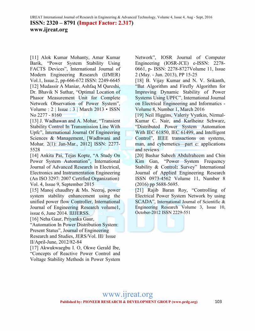
experiment. Figure no 2 gives the circuit of
the grid network comprising generators
3nos, loads 3nos and Transmission lines
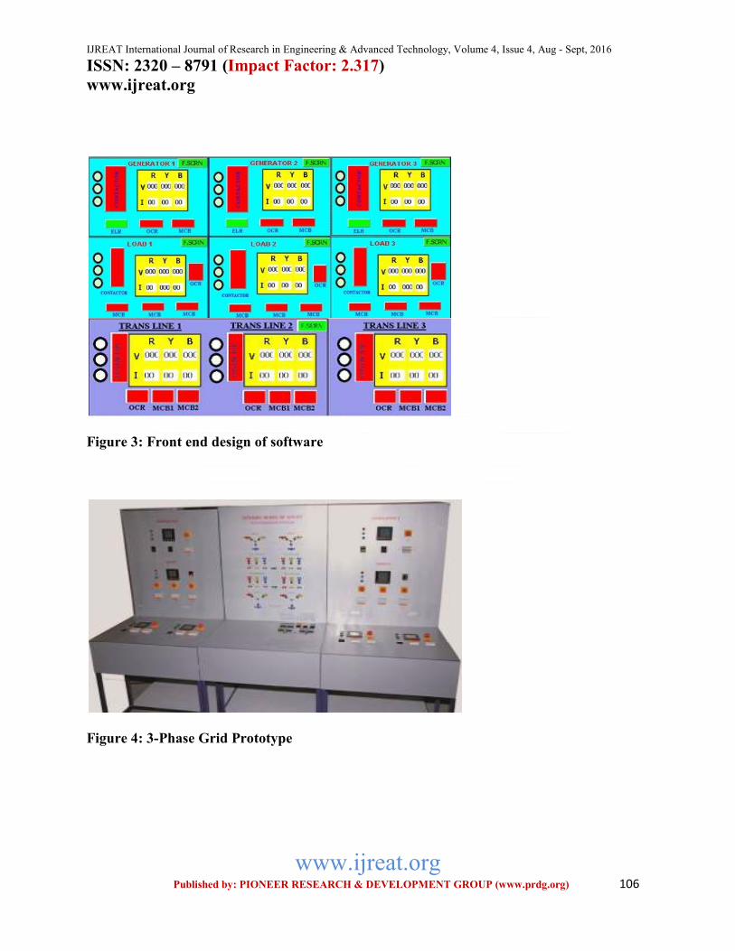
3nos for experimental setup on the 3-Phase
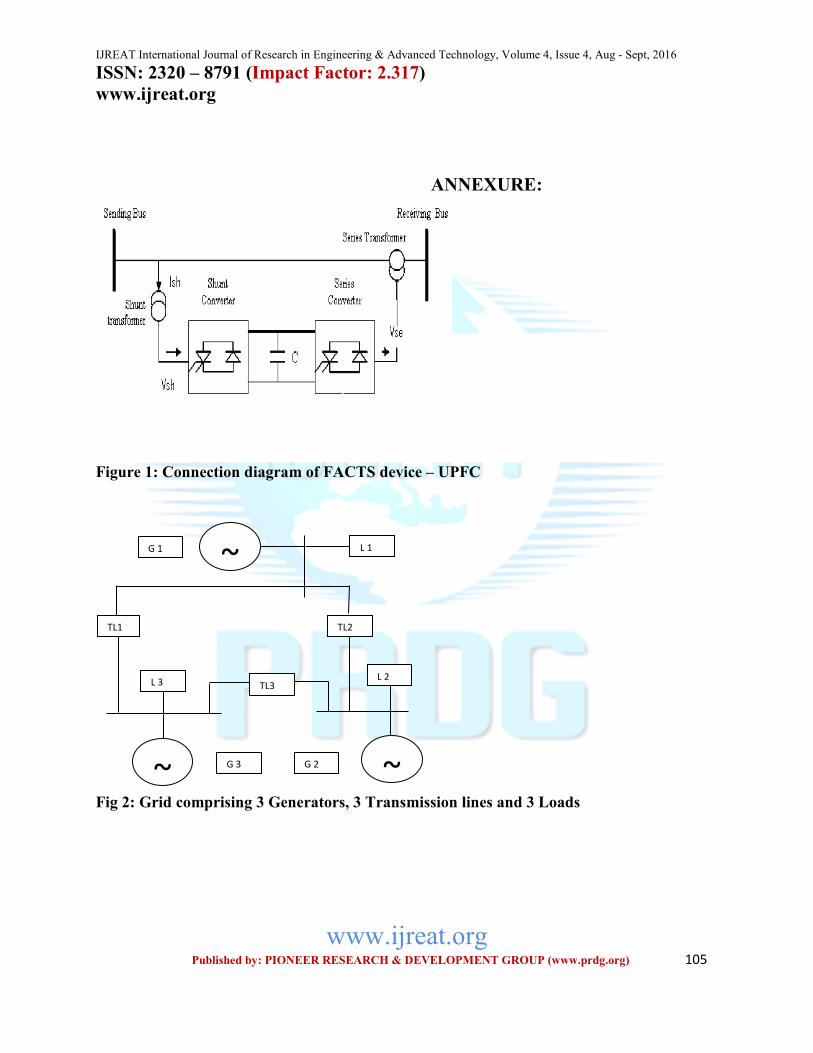
Grid Prototype shown in figure no 4 where
as figure no 3 gives the front end design of
the software used to monitor & control the
3-Phase Grid Prototype through the
computer.
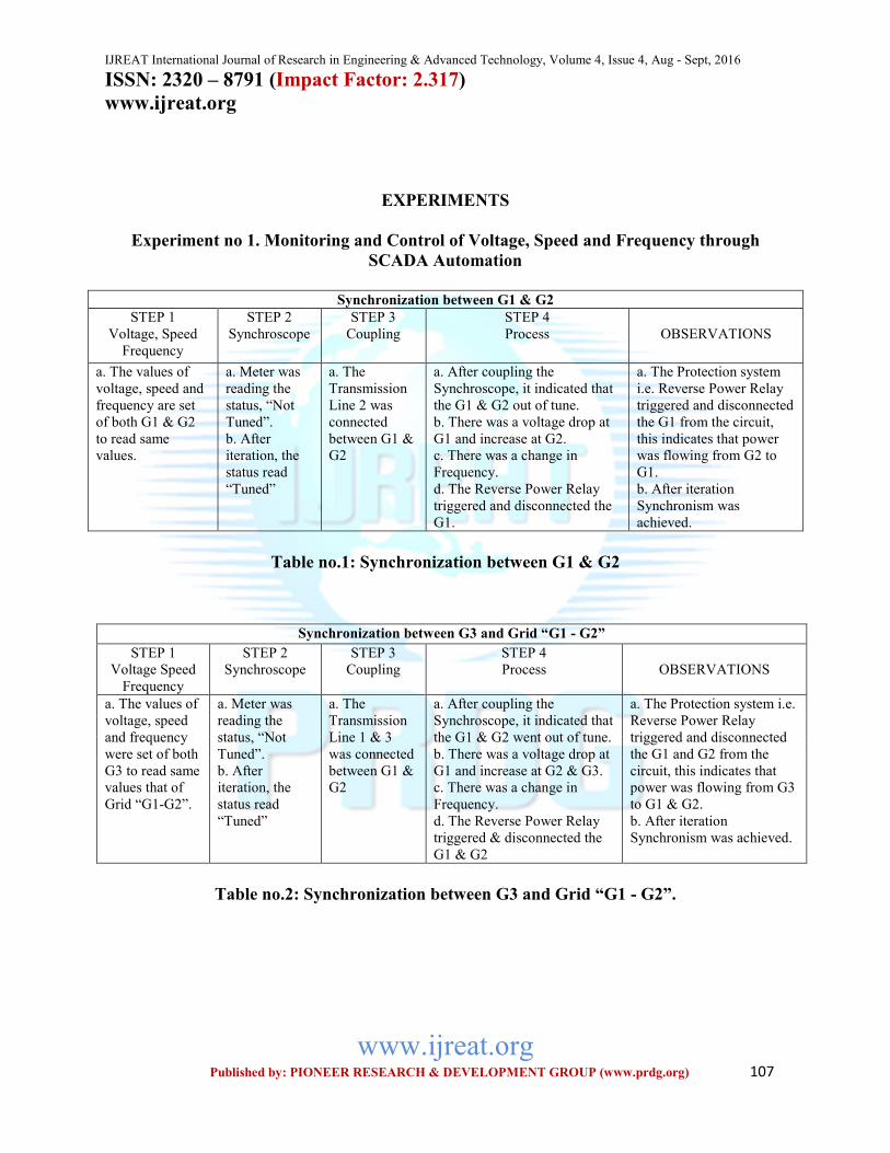
Experiments were conducted on monitoring
and control of voltage, speed and frequency
of generator through SCADA automation in
various steps given in the table no 1, in this
table the last column gives the observations
made in the experiment. Table no 2 studies
the synchronization between G3 and grid
“G1 & G2” along with the observations.
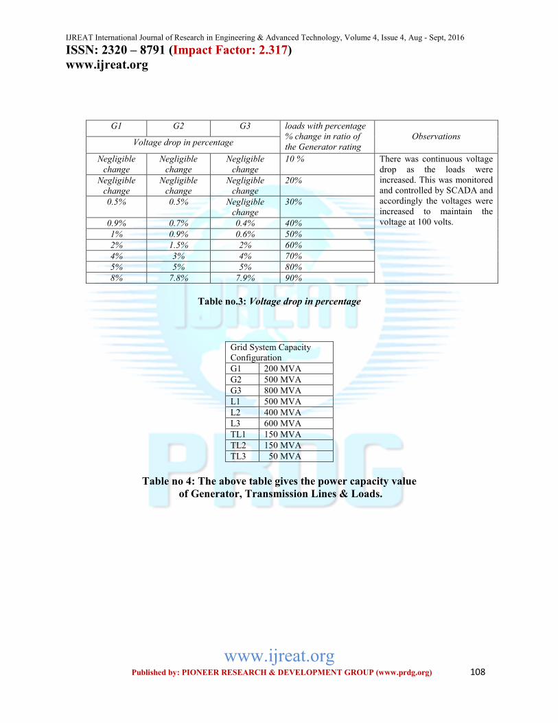
Table no 3 lists out the voltage drop of the
generator bus bar and loads with percentage
% change in the ratio of the generator
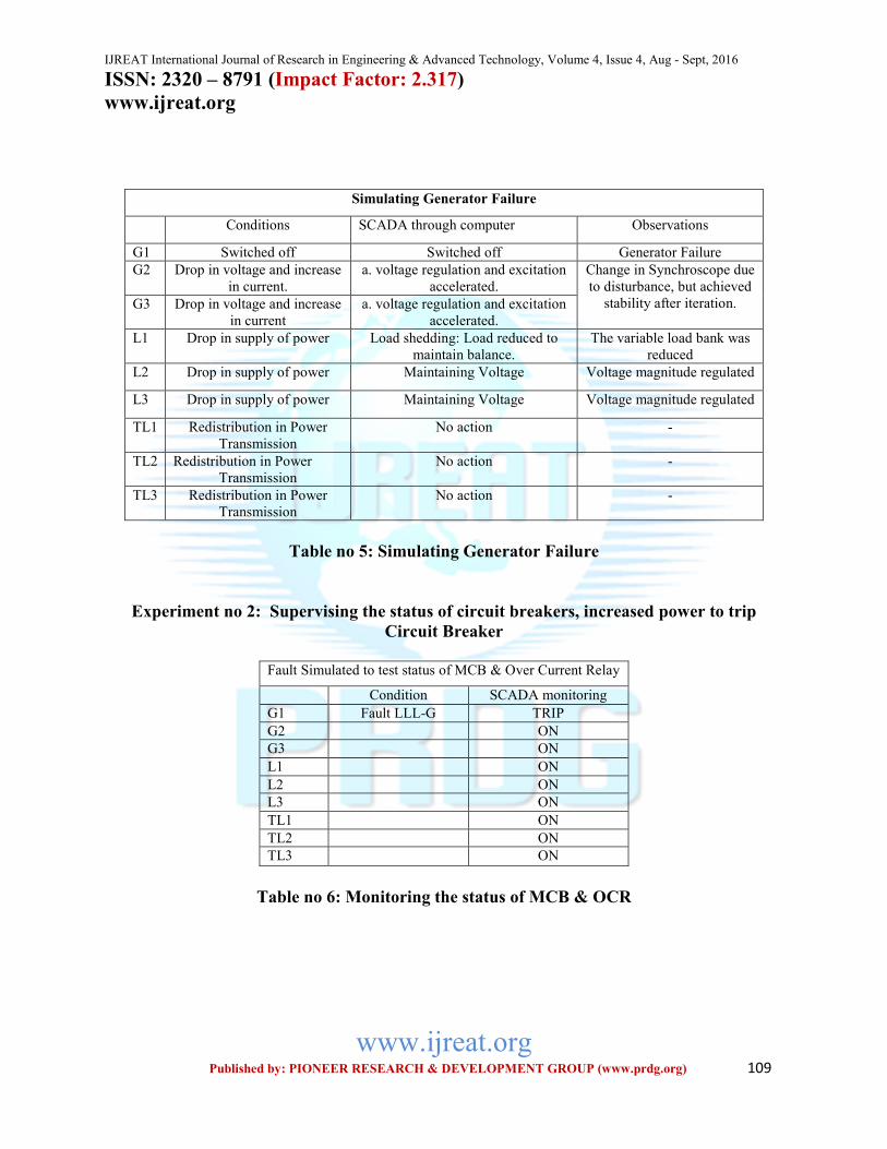
capacity. Table no 5 describes various
conditions which were observed during the
process of generator failure i.e. G1 switched
off whereas in G2 and G3 there was a drop
in the voltage and increment in the current.
In L1, L2 & L3 there was a drop in the
supply of power and in TL1, TL2 and TL3 a
reduction in power transmission. Here the
function of SCADA operated through the
computer is also listed in column 2 and
related observation in column 3 of the table.
Experiment no 2 was conducted on
supervising the status of circuit breakers,
(increased power to trip circuit breaker).
Table no 6 gives the monitoring status of
MCB and Over Current Relay under the
fault condition of LLL-G.
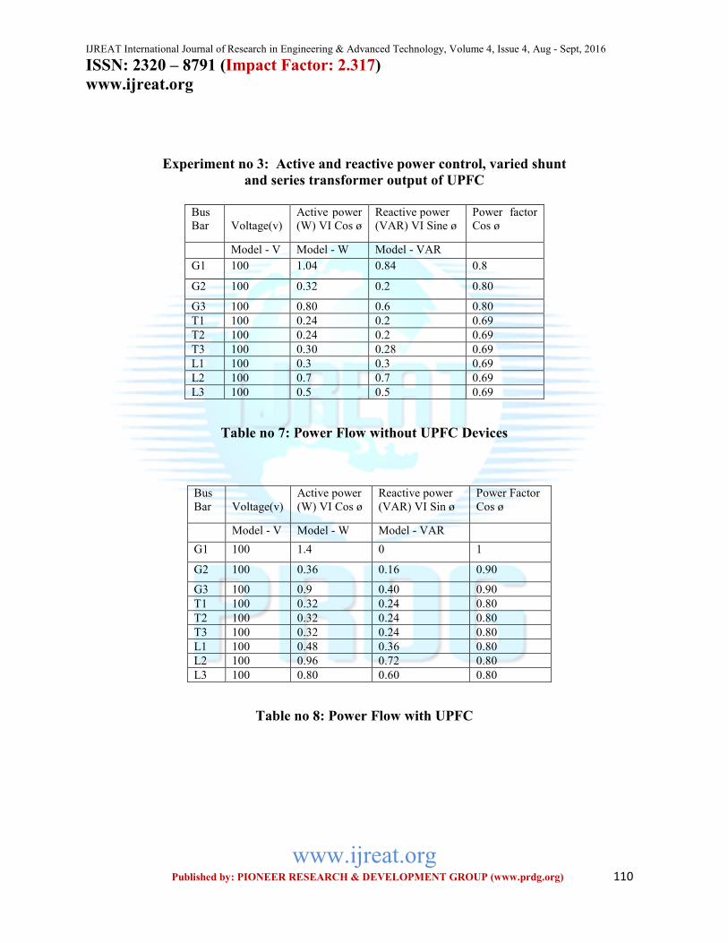
Experiment no 3 deals with the active and
reactive power control which had varied
shunt and series transformer output from the
UPFC. Here the table no 7 shows power
IJREAT International Journal of Research in Engineering & Advanced Technology, Volume 4, Issue 4, Aug - Sept, 2016 ISSN: 2320 – 8791 (Impact Factor: 2.317)
www.ijreat.org
www.ijreat.org Published by: PIONEER RESEARCH & DEVELOPMENT GROUP (www.prdg.org) 102
flow without UPFC device and table no 8
gives the power flow with UPFC device.
Here it can be seen that with the presence of
the UPFC device power factor has increased
and consequently active power (W) where as
the reactive power (VARS) changed
accordingly.
REFERENCES
[1] Saurabh Jain, Madhur A Sinha and Dr
Anand Khare, “Contrsution of 3-Phase Grid
Prototype”, International Journal of
Research in Engineering & Advanced
Technology, Volume 4, Issue 3, June – July.
2016
[2] Soheil Ganjefar, M. Rezaei, “A New
Method to Control Dynamic Stability of
Power System through Wave Variables and
Signal Prediction via Internet”, International
Journal of Recent Trends in Engineering,
Vol 1, No. 1, May 2009.
[3] Abdul Ghani Abro and Junita Mohamad-
Saleh, “Control Of Power System Stability –
Reviewed Solutions Based On Intelligent
Systems”, International Journal of
Innovative Computing, Information and
Control Volume 8, Number 10(A), October
2012.
[4] Byung Ha Lee and Kwang Y. Lee.,
“Dynamic and Static Voltage Stability
Enhancement Of Power Systems”, LEEE
Transactions on Power Systems, Vol. 8, No.
1, February 1993
[5] Kiran R, BR Lakshmikantha, RV
Parimala, “Observability & Controllability
of a power system by optimizing
performance of PMUs & FACTS
controller”, International Journal of
Advanced Research in Electrical,
Electronics & Instrumentation Engineering
Vol. 2, Issue 6, June 2013.
[6] Nagasubbaiah.V Rama Subbanna S,
Venkateswar Reddy, “Dynamic Stability
Enhancement through PSS And UPFC”,
International Journal of Technical Research
and Applications, Volume 3, Issue 5
(September-October, 2015), PP. 149-157.
[7] Luis Fabiano dos Santos, Galina
Antonova, Mats Larsson, Sergio Fujii,
“Wide Area Monitoring and Control The
Use of Synchro-phasor for Wide Area
Monitoring of Electrical Power Grids”
[8] Yuyao Chen, Yanping Zhang, Jian
Zhang, Yanjun Zhang, Lixin Song, “A Full
Dynamic Voltage Stability Research Based
on Time-domain Simulation”, Energy and
Power Engineering, 2013, 5, 769-773
doi:10.4236/epe.2013.54B148 Published
Online July 2013
[9] Garng M. Huang and Liang Zhao,
“Measurement based Voltage Stability
Monitoring of Power system”,
[10] Lee-Cheun Hau, Jer-Vui Lee, Yea-Dat
Chuah and An-Chow Lai, “Smart Grid –
The Present and Future of Smart Physical
Protection: A Review”, International Journal
of Energy, Information & Communications
Vol. 4, Issue 4, August, 2013
IJREAT International Journal of Research in Engineering & Advanced Technology, Volume 4, Issue 4, Aug - Sept, 2016 ISSN: 2320 – 8791 (Impact Factor: 2.317)
www.ijreat.org
www.ijreat.org Published by: PIONEER RESEARCH & DEVELOPMENT GROUP (www.prdg.org) 103
[11] Alok Kumar Mohanty, Amar Kumar
Barik, “Power System Stability Using
FACTS Devices”, International Journal of
Modern Engineering Research (IJMER)
Vol.1, Issue.2, pp-666-672 ISSN: 2249-6645
[12] Mudassir A Maniar, Ashfaq M Qureshi,
Dr. Bhavik N Suthar, “Optimal Location of
Phasor Measurement Unit for Complete
Network Observation of Power System”,
Volume : 2 | Issue : 3 | March 2013 • ISSN
No 2277 - 8160
[13] J. Wadhawan and A. Mohar, “Transient
Stability Control In Transmission Line With
Upfc”, International Journal Of Engineering
Sciences & Management, [Wadhwani and
Mohar, 2(1): Jan-Mar., 2012] ISSN: 2277-
5528
[14] Ankita Pai, Tejas Kopte, “A Study On
Power System Automation”, International
Journal of Advanced Research in Electrical,
Electronics and Instrumentation Engineering
(An ISO 3297: 2007 Certified Organization)
Vol. 4, Issue 9, September 2015
[15] Manoj chaudhry & Ms. Neeraj, power
system stability enhancement using the
unified power flow Controller, International
Journal of Engineering Research volume1,
issue 6, June 2014. IIJJERSS.olume 1 |
[16] Neha Gaur, Priyanka Gaur,
“Automation In Power Distribution System:
Present Status”, Journal of Engineering
Research and Studies, JERS/Vol. III/ Issue
II/April-June, 2012/82-84
[17] Akwukwaegbu I. O, Okwe Gerald Ibe,
“Concepts of Reactive Power Control and
Voltage Stability Methods in Power System
Network”, IOSR Journal of Computer
Engineering (IOSR-JCE) e-ISSN: 2278-
0661, p- ISSN: 2278-8727Volume 11, Issue
2 (May. - Jun. 2013), PP 15-25
[18] B. Vijay Kumar and N. V. Srikanth,
“Bat Algorithm and Firefly Algorithm for
Improving Dynamic Stability of Power
Systems Using UPFC”, International Journal
on Electrical Engineering and Informatics -
Volume 8, Number 1, March 2016
[19] Neil Higgins, Valeriy Vyatkin, Nirmal-
Kumar C. Nair, and Karlheinz Schwarz,
“Distributed Power System Automation
With IEC 61850, IEC 61499, and Intelligent
Control”, IEEE transactions on systems,
man, and cybernetics—part c: applications
and reviews
[20] Bashar Sabeeh Abdulraheem and Chin
Kim Gan, “Power System Frequency
Stability & Control: Survey” International
Journal of Applied Engineering Research
ISSN 0973-4562 Volume 11, Number 8
(2016) pp 5688-5695.
[21] Rajib Baran Roy, “Controlling of
Electrical Power System Network by using
SCADA”, International Journal of Scientific &
Engineering Research Volume 3, Issue 10,
October-2012 ISSN 2229-551

IJREAT International Journal of Research in Engineering & Advanced Technology, Volume 4, Issue 4, Aug - Sept, 2016 ISSN: 2320 – 8791 (Impact Factor: 2.317)
www.ijreat.org
www.ijreat.org Published by: PIONEER RESEARCH & DEVELOPMENT GROUP (www.prdg.org) 104
ABOUT THE AUTHORS
SAURABH JAIN
He has obtained M. Tech. (with
gold medal) in Electrical
Engineering (Specialization in
Control and Instrumentation) (2003) from M.N.N.I.T.,
Allahabad. His research interests are in the
field of automation and stability control of
power generation and transmission systems.
He has authored several text books in the
field of Control Engineering and
Automation. He has 15 years of experience
in teaching & research. At present, he is
working as an Associate Professor in Swami
Vivekanand College of Engineering, Indore
and he is a research scholar at Dept. of ECE,
Bhagwant University, Ajmer.
DR. ANAND KHARE
He is Professor in an affiliated
college of JNTU University,
Hyderabad and also Research
Director of MRPC Company,
Hyderabad. Formerly he was
professor in I.I.Sc. Bangalore.
Several research scholars have received their
Ph.D. under his guidance.
ACKNOWLEDGEMENT
Thanks to DR. RAMLEELA KHARE,
Director Research, The ISRC Company,
Hyderabad, for his suggestions in
constructing the model.
IJREAT International Journal of Research in Engineering & Advanced Technology, Volume 4, Issue 4, Aug - Sept, 2016 ISSN: 2320 – 8791 (Impact Factor: 2.317)
www.ijreat.org
www.ijreat.org Published by: PIONEER RESEARCH & DEVELOPMENT GROUP (www.prdg.org) 105
ANNEXURE:
Figure 1: Connection diagram of FACTS device – UPFC
Fig 2: Grid comprising 3 Generators, 3 Transmission lines and 3 Loads
G 3 G 2
G 1 L 1
L 2 L 3
TL3
TL2 TL1
~
~ ~
IJREAT International Journal of Research in Engineering & Advanced Technology, Volume 4, Issue 4, Aug - Sept, 2016 ISSN: 2320 – 8791 (Impact Factor: 2.317)
www.ijreat.org
www.ijreat.org Published by: PIONEER RESEARCH & DEVELOPMENT GROUP (www.prdg.org) 106
Figure 3: Front end design of software
Figure 4: 3-Phase Grid Prototype
IJREAT International Journal of Research in Engineering & Advanced Technology, Volume 4, Issue 4, Aug - Sept, 2016 ISSN: 2320 – 8791 (Impact Factor: 2.317)
www.ijreat.org
www.ijreat.org Published by: PIONEER RESEARCH & DEVELOPMENT GROUP (www.prdg.org) 107
EXPERIMENTS
Experiment no 1. Monitoring and Control of Voltage, Speed and Frequency through
SCADA Automation
Synchronization between G1 & G2
STEP 1
Voltage, Speed
Frequency
STEP 2
Synchroscope
STEP 3
Coupling
STEP 4
Process
OBSERVATIONS
a. The values of
voltage, speed and
frequency are set
of both G1 & G2
to read same
values.
a. Meter was
reading the
status, “Not
Tuned”.
b. After
iteration, the
status read
“Tuned”
a. The
Transmission
Line 2 was
connected
between G1 &
G2
a. After coupling the
Synchroscope, it indicated that
the G1 & G2 out of tune.
b. There was a voltage drop at
G1 and increase at G2.
c. There was a change in
Frequency.
d. The Reverse Power Relay
triggered and disconnected the
G1.
a. The Protection system
i.e. Reverse Power Relay
triggered and disconnected
the G1 from the circuit,
this indicates that power
was flowing from G2 to
G1.
b. After iteration
Synchronism was
achieved.
Table no.1: Synchronization between G1 & G2
Table no.2: Synchronization between G3 and Grid “G1 - G2”.
Synchronization between G3 and Grid “G1 - G2”
STEP 1
Voltage Speed
Frequency
STEP 2
Synchroscope
STEP 3
Coupling
STEP 4
Process
OBSERVATIONS
a. The values of
voltage, speed
and frequency
were set of both
G3 to read same
values that of
Grid “G1-G2”.
a. Meter was
reading the
status, “Not
Tuned”.
b. After
iteration, the
status read
“Tuned”
a. The
Transmission
Line 1 & 3
was connected
between G1 &
G2
a. After coupling the
Synchroscope, it indicated that
the G1 & G2 went out of tune.
b. There was a voltage drop at
G1 and increase at G2 & G3.
c. There was a change in
Frequency.
d. The Reverse Power Relay
triggered & disconnected the
G1 & G2
a. The Protection system i.e.
Reverse Power Relay
triggered and disconnected
the G1 and G2 from the
circuit, this indicates that
power was flowing from G3
to G1 & G2.
b. After iteration
Synchronism was achieved.
IJREAT International Journal of Research in Engineering & Advanced Technology, Volume 4, Issue 4, Aug - Sept, 2016 ISSN: 2320 – 8791 (Impact Factor: 2.317)
www.ijreat.org
www.ijreat.org Published by: PIONEER RESEARCH & DEVELOPMENT GROUP (www.prdg.org) 108
Table no.3: Voltage drop in percentage
Grid System Capacity
Configuration
G1 200 MVA
G2 500 MVA
G3 800 MVA
L1 500 MVA
L2 400 MVA
L3 600 MVA
TL1 150 MVA
TL2 150 MVA
TL3 50 MVA
Table no 4: The above table gives the power capacity value
of Generator, Transmission Lines & Loads.
G1 G2 G3 loads with percentage
% change in ratio of
the Generator rating
Observations Voltage drop in percentage
Negligible
change
Negligible
change
Negligible
change
10 % There was continuous voltage
drop as the loads were
increased. This was monitored
and controlled by SCADA and
accordingly the voltages were
increased to maintain the
voltage at 100 volts.
Negligible
change
Negligible
change
Negligible
change
20%
0.5% 0.5% Negligible
change
30%
0.9% 0.7% 0.4% 40%
1% 0.9% 0.6% 50%
2% 1.5% 2% 60%
4% 3% 4% 70%
5% 5% 5% 80%
8% 7.8% 7.9% 90%
IJREAT International Journal of Research in Engineering & Advanced Technology, Volume 4, Issue 4, Aug - Sept, 2016 ISSN: 2320 – 8791 (Impact Factor: 2.317)
www.ijreat.org
www.ijreat.org Published by: PIONEER RESEARCH & DEVELOPMENT GROUP (www.prdg.org) 109
Simulating Generator Failure
Conditions SCADA through computer Observations
G1 Switched off Switched off Generator Failure
G2 Drop in voltage and increase
in current.
a. voltage regulation and excitation
accelerated.
Change in Synchroscope due
to disturbance, but achieved
stability after iteration. G3 Drop in voltage and increase
in current
a. voltage regulation and excitation
accelerated.
L1 Drop in supply of power Load shedding: Load reduced to
maintain balance.
The variable load bank was
reduced
L2 Drop in supply of power Maintaining Voltage Voltage magnitude regulated
L3 Drop in supply of power Maintaining Voltage Voltage magnitude regulated
TL1 Redistribution in Power
Transmission
No action -
TL2 Redistribution in Power
Transmission
No action -
TL3 Redistribution in Power
Transmission
No action -
Table no 5: Simulating Generator Failure
Experiment no 2: Supervising the status of circuit breakers, increased power to trip
Circuit Breaker
Fault Simulated to test status of MCB & Over Current Relay
Condition SCADA monitoring
G1 Fault LLL-G TRIP
G2 ON
G3 ON
L1 ON
L2 ON
L3 ON
TL1 ON
TL2 ON
TL3 ON
Table no 6: Monitoring the status of MCB & OCR
IJREAT International Journal of Research in Engineering & Advanced Technology, Volume 4, Issue 4, Aug - Sept, 2016 ISSN: 2320 – 8791 (Impact Factor: 2.317)
www.ijreat.org
www.ijreat.org Published by: PIONEER RESEARCH & DEVELOPMENT GROUP (www.prdg.org) 110
Experiment no 3: Active and reactive power control, varied shunt
and series transformer output of UPFC
Bus
Bar
Voltage(v)
Active power
(W) VI Cos ø
Reactive power
(VAR) VI Sine ø
Power factor
Cos ø
Model - V Model - W Model - VAR
G1 100 1.04 0.84 0.8
G2 100 0.32 0.2 0.80
G3 100 0.80 0.6 0.80
T1 100 0.24 0.2 0.69
T2 100 0.24 0.2 0.69
T3 100 0.30 0.28 0.69
L1 100 0.3 0.3 0.69
L2 100 0.7 0.7 0.69
L3 100 0.5 0.5 0.69
Table no 7: Power Flow without UPFC Devices
Bus
Bar
Voltage(v)
Active power
(W) VI Cos ø
Reactive power
(VAR) VI Sin ø
Power Factor
Cos ø
Model - V Model - W Model - VAR
G1 100 1.4 0 1
G2 100 0.36 0.16 0.90
G3 100 0.9 0.40 0.90
T1 100 0.32 0.24 0.80
T2 100 0.32 0.24 0.80
T3 100 0.32 0.24 0.80
L1 100 0.48 0.36 0.80
L2 100 0.96 0.72 0.80
L3 100 0.80 0.60 0.80
Table no 8: Power Flow with UPFC


![Untitled-2 [] · 2012. 5. 15. · line 120v variac 120v primary 120 v line 120v va prlmary 60v secondary supplementary transformer volt-ampere rating same as variac autotransformer](https://img.pdfslide.us/doc/110x75/5fe56083bae61f036b1baf66/untitled-2-2012-5-15-line-120v-variac-120v-primary-120-v-line-120v-va-prlmary.jpg)