Embed Size (px)
Citation preview
19
STABILITY CHARTS FOR UNSUPPORTED PLANE STRAIN TUNNEL HEADINGS IN HOMOGENEOUS UNDRAINED CLAY
Jim Shiau1, Mathew Sams1, Fadhil Al-Asadi1, Mohammad Mirza Hassan1 1School of Civil Engineering and Surveying, University of Southern Queensland, Australia
*Corresponding Author, Received: 12 Sept. 2017, Revised: 10 Oct. 2017, Accepted: 10 Nov. 2017
ABSTRACT: This paper investigates the stability of plane strain tunnel headings in undrained soils. Using the factor of safety approach via the strength reduction technique, the idealised tunnel heading models are studied using the finite difference program FLAC. This problem is also similar to underground long wall excavations in plane strain condition. The finite difference results are presented alongside upper and lower bound limit solutions for validation. A thorough comparison between these two methods finds a very good agreement. Design charts are presented for a wide range of practical scenarios using dimensionless ratios, similar to Taylor’s design charts used for slope stability. Typical examples are presented to illustrate the usefulness for practising engineers.
Keywords: Plain Strain Heading, Undrained Clay, Stability, Strength Reduction Method, Design Chart
1. INTRODUCTION
The research of tunnel heading stability was initiated with [1] who studied the plastic flow of clay soil in vertical openings such as sheet pile walls and drew a comparison to the stability of a tunnel heading face. The stability number was initially defined in Eq. (1).
/ (1)
Where σs is the uniform surcharge pressure on the surface and σt is the uniform internal tunnel pressure. The cover depth above the crown of the tunnel is C, while the tunnel diameter is D. The undrained shear strength of soil and the unit weight of the soil are represented by Su and γ respectively.
During the 1970s at Cambridge University, numerous studies were completed on centrifuge models by [2]. The work was culminated by [3] who investigated the experimental and theoretical undrained collapse of three-dimensional cylindrical tunnel headings in normal consolidated kaolin under different geometry and gravity regimes. Davis [4] and Sloan [5] built further on the stability ratio by using upper and lower bound solutions using the classical limit theorems for tunnel collapse in cohesive undrained conditions.
Augarde [6] revisited the plane strain heading problem due to the recent improvements to finite element limit analysis methods developed by [7-10]. A number of papers were achieved in the area of tunnel stability by [11-17]. In particular [6] extended the limit analysis theory on tunnel heading by investigating a three-dimensional
multiblock failure mechanism for frictional and cohesive soil by the use of a spatial discretization technique.
All of these studies investigated the stability number as a function of dimensionless parameters. The problem was regarded as to find the limiting value of a pressure ratio (σs – σt)/Su that is a function of the independent parameters such as the depth ratio C/D and the strength ratio Su/γD. It is possible to simulate an unsupported excavation in green-field conditions by neglecting σs and σt, or a situation with equal surcharge and internal supportive pressure. It can also be a factor of safety problem that is a function of the depth ratio C/D and the strength ratio Su/γD ~ a similar approach in Taylor’s design charts for slope stability analysis [18].
This paper presents a comprehensive parametric undrained analysis for the stability of plain strain heading in an unsupported excavation in green-field conditions. A strength reduction technique is used to determine the factor of safety in cohesive soils over a wide parametric range. Numerical results from the strength reduction technique using FLAC are compared to those obtained by the finite element limit analysis. Design stability charts are also presented for practical uses.
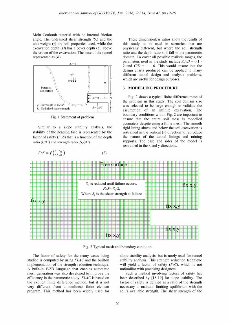
2. STATEMENT OF PROBLEM
The problem is a two dimensional plane strain heading condition by assuming the longitudinal section as a very long excavation [6]. Fig. 1 shows the problem definition. The soil medium is considered as undrained and is modelled as a uniform Tresca material, which is the same as a
International Journal of GEOMATE, Jan., 2018, Vol.14, Issue 41, pp.19-26Geotec., Const. Mat. & Env., DOI: https://doi.org/10.21660/2018.41.29138ISSN: 2186-2982 (Print), 2186-2990 (Online), Japan
International Journal of GEOMATE, Jan., 2018, Vol.14, Issue 41, pp.19-26
20
Mohr-Coulomb material with no internal friction angle. The undrained shear strength (Su) and the unit weight (γ) are soil properties used, while the excavation depth (D) has a cover depth (C) above the crown of the excavation. The base of the tunnel represented as (B).
Fig. 1 Statement of problem
Similar to a slope stability analysis, the
stability of the heading face is represented by the factor of safety (FoS) that is a function of the depth ratio (C/D) and strength ratio (Su/γD).
, (2)
These dimensionless ratios allow the results of
this study to be used in scenarios that are physically different, but where the soil strength ratio and the depth ratio still fall in the parametric domain. To cover all possible realistic ranges, the parameters used in the study include Su/γD = 0.1 - 2 and C/D = 1 - 6. This would ensure that the design charts produced can be applied to many different tunnel design and analysis problems, which are useful for design purposes. 3. MODELLING PROCEDURE
Fig. 2 shows a typical finite difference mesh of
the problem in this study. The soil domain size was selected to be large enough to validate the assumption of an infinite excavation. The boundary conditions within Fig. 2 are important to ensure that the entire soil mass is modelled accurately despite using a finite mesh. The smooth rigid lining above and below the soil excavation is restrained in the vertical (y) direction to reproduce the nature of the tunnel linings and mining supports. The base and sides of the model is restrained in the x and y directions.
Fig. 2 Typical mesh and boundary condition
The factor of safety for the many cases being studied is computed by using FLAC and the built-in implementation of the strength reduction technique. A built-in FISH language that enables automatic mesh generation was also developed to improve the efficiency in the parametric study. FLAC is based on the explicit finite difference method, but it is not very different from a nonlinear finite element program. This method has been widely used for
slope stability analysis, but is rarely used for tunnel stability analysis. This strength reduction technique will yield a factor of safety (FoS), which is not unfamiliar with practising designers.
Such a method involving factors of safety has been described by [18-19] for slope stability. The factor of safety is defined as a ratio of the strength necessary to maintain limiting equilibrium with the soil’s available strength. The shear strength of the
Su is reduced until failure occurs. FoS= Su/Sf
Where Sf is the shear strength at failure
International Journal of GEOMATE, Jan., 2018, Vol.14, Issue 41, pp.19-26
21
material is reduced until the limiting condition is found. This can be compared to the studies originated from [1] where the uniform surcharge pressure is increased until the limiting condition is found. If failure occurs initially, the shear strength of
the soil is increased by amplifying the cohesion and friction angle until limiting equilibrium or failure state is reached. Once the actual and critical strength are known, the factor of safety can then be calculated.
4. RESULTS AND DISCUSSIONS
Using the strength reduction technique within the
finite difference program FLAC, factor of safety (FoS) values were obtained for a range of parameters for an unsupported tunnel heading in undrained soil. The two dimensionless parameters used in the studies are the depth ratio (C/D) and the strength ratio (Su/γD).
It is important to compare the finite difference
technique with another numerical investigation. Using finite element limit analysis, upper bound and lower bound, factors of safety have been calculated using OptumG2 over the same parametric ranges. The numerical procedures used in OptumG2 are based on the limit theorems of classical plasticity [7 - 10]
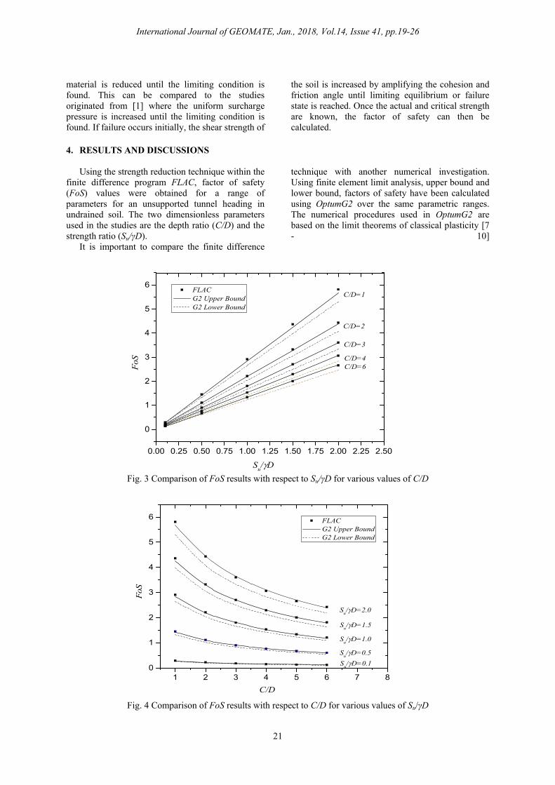
Fig. 3 Comparison of FoS results with respect to Su/γD for various values of C/D
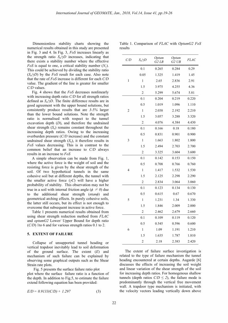
Fig. 4 Comparison of FoS results with respect to C/D for various values of Su/γD
0.00 0.25 0.50 0.75 1.00 1.25 1.50 1.75 2.00 2.25 2.50
0
1
2
3
4
5
6
C/D=6C/D=4
C/D=3
C/D=2
C/D=1
FoS
Su/D
FLAC G2 Upper Bound G2 Lower Bound
1 2 3 4 5 6 7 80
1
2
3
4
5
6
Su/D=0.1
Su/D=0.5
Su/D=1.0
Su/D=1.5
FoS
C/D
FLAC G2 Upper Bound G2 Lower Bound
Su/D=2.0
International Journal of GEOMATE, Jan., 2018, Vol.14, Issue 41, pp.19-26
22
Dimensionless stability charts showing the numerical results obtained in this study are presented in Fig. 3 and 4. In Fig. 3, FoS increases linearly as the strength ratio Su/γD increases, indicating that there exists a stability number where the effective FoS is equal to one, a critical stability number (Nc). This could be achieved by dividing the stability ratio (Su/γD) by the FoS result for each case. Also note that the rate of FoS increase is different for each C/D value. The gradient of the line is greater for smaller C/D values. Fig. 4 shows that the FoS decreases nonlinearly with increasing depth ratio C/D for all strength ratios defined as Su/γD. The finite difference results are in good agreement with the upper bound solutions, but consistently produce results that are 3-5% larger than the lower bound solutions. Note the strength ratio is normalised with respect to the tunnel excavation depth (D), and therefore the undrained shear strength (Su) remains constant throughout the increasing depth ratios. Owing to the increasing overburden pressure (C/D increase) and the constant undrained shear strength (Su), it therefore results in FoS values decreasing. This is in contrast to the common belief that an increase to C/D always results in an increase to FoS A simple observation can be made from Fig. 1, where the active force is the weight of soil and the resisting force is given by the shear strength of the soil. Of two hypothetical tunnels in the same cohesive soil but at different depths, the tunnel with the smaller active force (γC) will have a higher probability of stability. This observation may not be true in a soil with internal friction angle (ϕ ≠ 0) due to the additional shear strength (σtanϕ) and geometrical arching effects. In purely cohesive soils, the latter still occurs, but its effect is not enough to overcome that subsequent increase in active force. Table 1 presents numerical results obtained from using shear strength reduction method from FLAC and optumG2 Lower/ Upper Bound for depth ratio (C/D) 1to 6 and for various strength ratios 0.1 to 2. 5. EXTENT OF FAILURE
Collapse of unsupported tunnel heading or vertical trapdoor inevitably lead to soil deformation of the ground surface. The extent (E) and mechanism of such failure can be explained by observing some graphical outputs such as the Shear Strain rate plots.
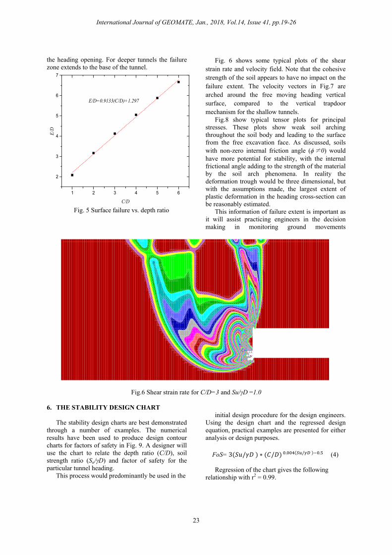
Fig. 5 presents the surface failure ratio plot plot where the surface failure ratio is a function of the depth. In addition to Fig.5, to estimate the failure extend following equation has been provided:
E/D = 0.9133(C/D) + 1.297 (3)
Table 1. Comparison of FLAC with OptumG2 FoS results
C/D Su/γD Optum G2 LB
Optum G2 UB
FLAC
1
0.1 0.265 0.284 0.29
0.05 1.325 1.419 1.45
1 2.65 2.836 2.91
1.5 3.975 4.255 4.36
2 5.299 5.674 5.81
2
0.1 0.204 0.219 0.220
0.5 1.019 1.096 1.110
1 2.038 2.192 2.210
1.5 3.057 3.288 3.320
2 4.076 4.384 4.430
3
0.1 0.166 0.18 0.180
0.5 0.831 0.901 0.900
1 1.663 1.802 1.800
1.5 2.494 2.703 2.700
2 3.325 3.604 3.600
4
0.1 0.142 0.153 0.150
0.5 0.708 0.766 0.760
1 1.417 1.532 1.530
1.5 2.125 2.298 2.290
2 2.834 3.064 3.060
5
0.1 0.123 0.134 0.130
0.5 0.615 0.67 0.670
1 1.231 1.34 1.330
1.5 1.846 2.009 2.000
2 2.462 2.679 2.660
6
0.1 0.109 0.119 0.120
0.5 0.545 0.596 0.600
1 1.09 1.191 1.210
1.5 1.635 1.787 1.810
2 2.18 2.383 2.420
The extent of failure surface investigation is
related to the type of failure mechanism the tunnel heading encountered at certain depths. Augarde [6] discusses the effects of increasing the soil weight and linear variation of the shear strength of the soil for increasing depth ratios. For homogenous shallow tunnels (depth ratios C/D ≤ 2), the failure mode is predominantly through the vertical free movement wall. A trapdoor type mechanism is initiated, with the velocity vectors leading vertically down above
International Journal of GEOMATE, Jan., 2018, Vol.14, Issue 41, pp.19-26
23
the heading opening. For deeper tunnels the failure zone extends to the base of the tunnel.
Fig. 5 Surface failure vs. depth ratio
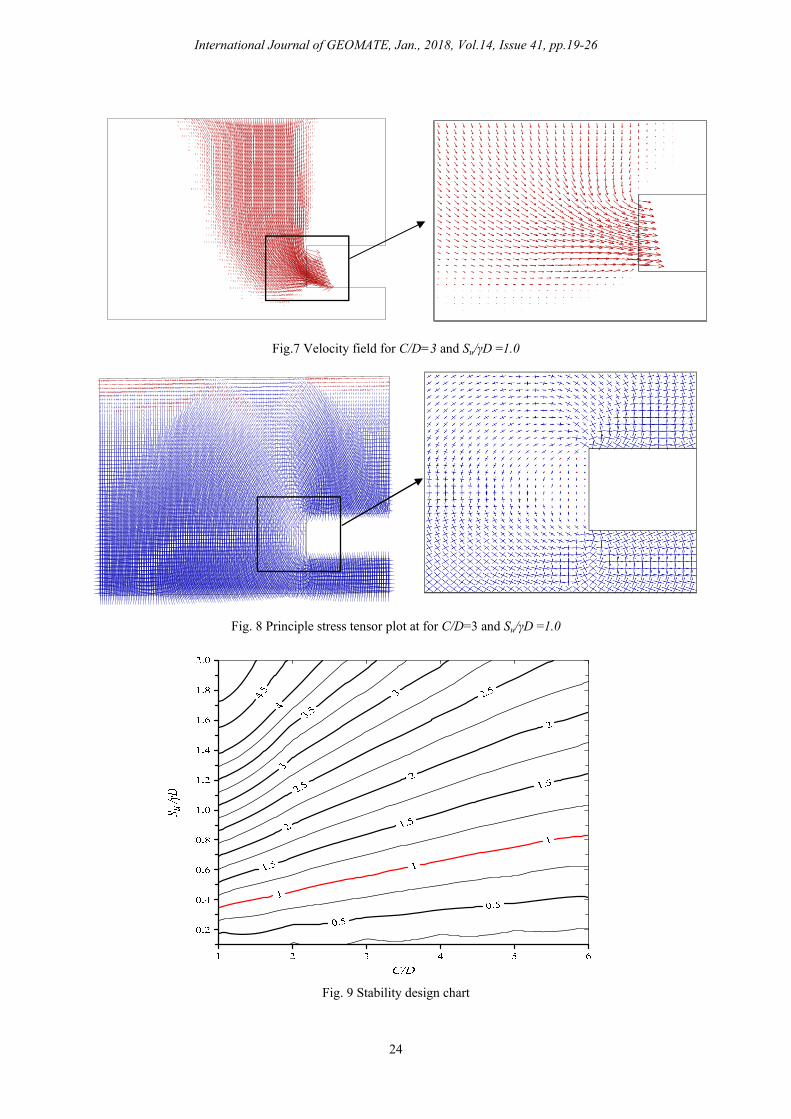
Fig. 6 shows some typical plots of the shear strain rate and velocity field. Note that the cohesive strength of the soil appears to have no impact on the failure extent. The velocity vectors in Fig.7 are arched around the free moving heading vertical surface, compared to the vertical trapdoor mechanism for the shallow tunnels.
Fig.8 show typical tensor plots for principal stresses. These plots show weak soil arching throughout the soil body and leading to the surface from the free excavation face. As discussed, soils with non-zero internal friction angle (ϕ≠0) would have more potential for stability, with the internal frictional angle adding to the strength of the material by the soil arch phenomena. In reality the deformation trough would be three dimensional, but with the assumptions made, the largest extent of plastic deformation in the heading cross-section can be reasonably estimated.
This information of failure extent is important as it will assist practicing engineers in the decision making in monitoring ground movements
Fig.6 Shear strain rate for C/D=3 and Su/γD =1.0
6. THE STABILITY DESIGN CHART The stability design charts are best demonstrated
through a number of examples. The numerical results have been used to produce design contour charts for factors of safety in Fig. 9. A designer will use the chart to relate the depth ratio (C/D), soil strength ratio (Su/γD) and factor of safety for the particular tunnel heading.
This process would predominantly be used in the
initial design procedure for the design engineers.
Using the design chart and the regressed design equation, practical examples are presented for either analysis or design purposes.
FoS=3 / ∗ / . / . (4)
Regression of the chart gives the following relationship with r2 = 0.99.
1 2 3 4 5 6
2
3
4
5
6
7
E/D
C/D
E/D=0.9133(C/D)+1.297
International Journal of GEOMATE, Jan., 2018, Vol.14, Issue 41, pp.19-26
24
Fig.7 Velocity field for C/D=3 and Su/γD =1.0
Fig. 8 Principle stress tensor plot at for C/D=3 and Su/γD =1.0
Fig. 9 Stability design chart
International Journal of GEOMATE, Jan., 2018, Vol.14, Issue 41, pp.19-26
25
6.1 Examples
Analysis of an existing unsupported tunnel
An existing mining excavation having no internal heading pressure and no surcharge pressure, determine the factor of safety for operations to continue, also determine the extent of failure in case of the collapse. Parameters are given as Su = 50 kPa, γ = 18 kN/m3, C = 10 m, and D = 2.5 m.
Using C/D = 4.0, Su/γD = 1.11, Eq. 4 gives a FoS of 1.68.
Using C/D = 4.0, Su/γD = 1.11, Fig. 9 gives an approximate FoS of 1.65.
An actual computer analysis of this particular case gives a FoS of 1.79.
Using Eq.3 the extent of failure calculated to be 12.38 m.
Analysis of a temporary unsupported tunnel heading
During the construction of a tunnel in soft soil, a factor of safety of 3 is targeted for a shallow tunnel maintenance job. While the machine requires maintenance, it will be unable to apply pressure to the tunnel face for a short period. A decision needs to be made whether stability will be maintained during this period, also determine the extent of failure in case of the collapse. Parameters are given as: Su = 30 kPa, γ = 18 kN/m3, C = 20 m and D = 5 m.
Using C/D = 4.0, Su/γD = 0.33, Eq.4 gives a FoS of 0.495.
Using C/D = 4.0, Su/γD = 0.33, Fig. 9 gives an approximate FoS of 0.48.
An actual computer analysis of this particular case gives a FoS of 0.537. Therefore, in this case, a failure to supply heading pressure would result in collapse. Ground improvement is needed to increase the soil strength.
Using Eq.3 the extent of failure calculated to be 24.751 m.
Design of an unsupported tunnel heading
The soil properties are known at the tunnel project site, and the diameter is specified. A target factor of safety is chosen, and the designers need to specify a maximum cover depth that will satisfy the target FoS. Parameters are given as: Su = 100 kPa, γ = 18 kN/m3, D = 5m, and the target FoS = 2.0 Using FoS = 2.0 and Su/γD = 1.11, Eq. 4 gives
a C value of 14.8 m. Using FoS = 2.0 and Su/γD = 1.11, Fig. 9 gives
an approximate C/D value of 2.85 and therefore C value of 14.5 m.
An actual computer analysis for this particular case gives a FoS of 2.08.
7. CONCLUSIONS Stability of plane strain headings and extent of
surface failure been studied in this paper using a factor of safety approach with the strength reduction technique. Numerical results were obtained using both the finite difference software FLAC and the finite element limit analysis software OptumG2. Design equation and charts were produced aligned with examples to determine the stability of excavated heading depths, such as idealized tunnel headings and long wall mining excavations. Using shear strength reduction method with FoS to plain strain heading stability is a useful approach to the initial design stage as it always provides direct information and understanding of tunnel stability. Future work is recommended to study the effect of surcharge, tunnel heading pressure and soil friction angle. Work should be done to study the effect of soil inclusion below structural lining. 8. REFERENCES [1] Broms, BB & Bennermark, H 1967, ‘Stability
of clay at vertical openings’, Journal of the Soil Mechanic & Foundations Division, Proceedings of the American Society of Civil Engineers, vol. 93, pp. 71- 93.
[2] Atkinson, JH, & Cairncross, AM 1973, ‘Collapse of a shallow tunnel in a Mohr–Coulomb material’, In Proceedings of the Symposium on the Role of Plasticity in Soil Mechanics, Cambridge, UK, 13–15 September 1973. Edited by A.C. Palmer. Cambridge University Engineering Department, University of Cambridge, Cambridge, UK. pp. 202–206.
[3] Mair RJ 1979, ‘Centrifugal modelling of tunnel construction in soft clay’, PhD thesis, University of Cambridge.
[4] Davis, EH, Gunn, MJ, Mair, RJ & Seneviratne, HN 1980, ‘The stability of shallow tunnels & underground openings in cohesive material’, Geotechnique, vol. 30, pp. 397-416.
[5] Sloan, SW, Assadi, A 1994, ‘Undrained stability of a plane strain heading’, Canadian Geotehcnical Journal, vol. 31, no. 3, pp. 443-450.
[6] Augarde, CE, Lyamin, AV & Sloan, SW 2003, ‘Stability of an undrained plane strain heading revisited’, Computers & Geotechnics, vol.30, pp. 419-430.
International Journal of GEOMATE, Jan., 2018, Vol.14, Issue 41, pp.19-26
26
[7] Lyamin, AV, & Sloan, SW 2002(a), ‘Lower bound limit analysis using non‐linear programming’, International Journal for Numerical Methods in Engineering, vol. 55, no. 5, pp. 573-611.
[8] Lyamin, AV & Sloan, SW 2002(b), ‘Upper bound limit analysis using linear finite elements & non‐linear programming’, International Journal for Numerical & Analytical Methods in Geomechanics, vol. 26, no. 2, pp. 181-216.
[9] Sloan, SW 1988, ‘Lower bound limit analysis using finite elements & linear programming’, International Journal for Numerical & Analytical Methods in Geomechanics, vol. 12, pp. 61-67.
[10] Sloan, SW 1989, ‘Upper bound limit analysis using finite elements & linear programming’, International Journal for Numerical & Analytical Methods in Geomechanics, vol. 13, pp. 263-282.
[11] Wilson, DW, Abbo, AJ, Sloan, SW, & Lyamin, AV 2014, ‘Undrained Stability of Dual Circular Tunnels’, International Journal of Geomechanics, vol. 14(1), pp. 69-79.
[12] Yamamoto, K, Lyamin, AV, Wilson, DW, Sloan, SW & Abbo, AJ 2011, ‘Stability of a circular tunnel in cohesive-frictional soil subjected to surcharge loading’, Computers & Geotechnics, vol. 38, pp. 504-514.
[13] Shiau, J, Sams, M and Chen, J 2016, ‘Stability charts for a tall tunnel in undrained clay’, Int. J. of GEOMATE, vol. 10(2), pp. 1764-1769
[14] Shiau, J, Sams, M and Lamb, B 2016, ‘Introducing advanced topics in geotechnical
engineering teaching – Tunnel modelling’, Int. J. of GEOMATE, vol. 10(1), pp. 1698-1705
[15] Shiau, J, Lamb, B and Sams, M 2016, ‘The use of sinkhole models in advanced geotechnical engineering teaching’, Int. J. of GEOMATE, vol. 10(2), pp. 1718-1724
[16] Shiau, J and Sams, M 2017, ‘Estimation of Tunneling Induced Ground Settlement Using Pressure Relaxation Method’, Int. J. of GEOMATE, vol. 13(39), pp. 132-139
[17] Shiau, J, Sams, M, Lamb, B, and Lobwein, J 2017, ‘Stability Charts for Unsupported Circular Tunnels in Cohesive Soils’, Int. J. of GEOMATE, vol. 13(39), pp. 95-102
[18] Taylor, DW 1937, ‘Stability of earth slopes.’ Journal of the Boston Society of Civil Engineers, vol. 24, no. 3, pp. 197-246.
[19] Bishop, AW 1955, ‘The use of slip circle in the stability analysis of slopes’, Geotechnique, vol. 5(1), pp. 7-17.
[20] FLAC 2003, Fast Lagrangian Analysis of Continua, Version 4.0, Itasca Consulting Group, Minneapolis, Minnesota, USA.
[21] Optum G2 2013, Optum Computational Engineering, Version 1.2014.10.1, Newcastle, Australia.
Copyright © Int. J. of GEOMATE. All rights reserved, including the making of copies unless permission is obtained from the copyright proprietors.