Embed Size (px)
Citation preview

•
•
•
UR.ZINSTR NTSTM K-BAR™
Multi-Point Insertion Mass Flow Element
User's Guide DOC# 360200, Rev. A
KURZ INSTRUMENTS, INC. 2411 GARDEN ROAD MONTEREY, CA 93940-5394 USA
Tel: (831)646-5911 Fax: (831)646-8901 www.kurz-lnstruments.com

•
•
•
1.
Electronic Version
The K-BAR ™ Multi-Point Insertion Mass Flow Element offers advanced solutions for today's demanding mass flow measurement needs. It provides superb accuracy and response time.
Kurz lnstrumentsTM has carefully designed this Guide to provide quick, concise answers to daily operational needs; and to serve as a source of reference information.
A small investment of time learning the information provided in this Guide provides maximum benefits and superior results.
II IMPORTANT ~ Please be certain to read all the safety information provided, and contact Kurz Instruments ™ immediately if a safety concern arises.
Please refer to the Appendices section for any information pertaining to your unit that was not covered in the main text of this Guide. After reading the information provided in this Guide, if there are any questions left unanswered, please contact Kurz lnstrumentsTMsupport personnel for additional assistance.
The Kurz Instruments™ toll-free service number is 1-800-424-7356. Other contact information is provided in the chapter titled "Obtaining Assistance".
If you are using the electronic version of this Guide (via Adobe Acrobat Reader version 3 or higher), you will find that the Table of contents has hyperlinks -just click on them to jump to the desired item. The document is also fully text-searchable using the Acrobat Reader "Find" function. It will also print nicely on your printer .
Document# 360200, Revision A Page 1-1 ©1999 KURZ INSTRUMENTS

• 1. PREFACE .............................................................................. 1-1
1.1 Table of Contents .................................................................. 1-2 1.2 Purpose and Scope ............................................................... :l-4 1.3 Warnings and Cautions .......................................................... 1-4 1.4 Disclaimers ............................................................................ t-5 1.5 Copyright ............................................................................... 1.-6 1.6 Trademarks ........................................................................... 1.-6 1.7 Conventions .......................................................................... 1.-6 1.8 Related Publications .............................................................. 1-7 1.9 Standard Warranty ................................................................ :l-8 1.1 0 Regulatory Information ............................................................. 1-9
2. INTRODUCTION .................................................................... 2-1 2.1 Applications .......................................................................... 2-2 2.2 Key Features ........................................................................ 2-2 2.3 Product Description ............................................................... 2-3 2.4 K-BAR™ Location and Sizing ............................................... 2-9 • 2.5 Mounting Hardware for the K-BAR™-.................................. 2-10
3. OPERATION ........................................................................... 3-1
4. MAINTENANCE ...................................................................... 4-1 4.1 Maintenance Overview ......................................................... A--f 4.2 Routine Maintenance ............................................................ A--2 4.3 Cleaning the Flow Element. .................................................. A-3 4.4 Verifying Sensor Electronics Output Signals ......................... A-4 4.5 Power Supply lnformation ..................................................... A-4 4.6 Calibration ............................................................................ A.-4
5. PROBLEM SOLVING ............................................................ S-1 5.1 External Factors .................................................................... 5-1 5.2 Testing for Proper Operation ................................................. 5-2 5.3 Typical Problems and Solutions ............................................ 5-2 5.4 Testing the Unit's Modules .................................................... .5-6
6. REPLACEMENT PARTS ....................................................... 6-1
7. FUNCTIONAL DESCRIPTION ............................................... 7-1 7.1 Sensing Technique ............................................................... 7.-1 • 7.2 Measurement Technique ...................................................... l-2
Document# 360200, Revision A Page 1-2 ©1999 KURZ INSTRUMENTS
•• 7.3 Sensor Technology ............................................................... 7.-3 7.4 Reading the Sensor .............................................................. 7.-3 7.S Sensor Responsiveness ....................................................... 1-3 7.6 Sensor Details ....................................................................... 7.-3 7. 7 Measurement Output ............................................................ 7.-4 7.8 Sensor Electronics ................................................................ ?.-4 7.9 Additional Information Resources .......................................... 7-S
8. OBTAINING ASSISTANCE ................................................... 8-1
9. RETURNING PRODUCTS ..................................................... 9-1 9.1 In-Warranty Returns .............................................................. 9-1 9.2 Non-Warranty Returns .......................................................... 9-1 9.3 All Equipment Returns .......................................................... 9-1
10. INSTAtl:ATION ................................................................... 1 0-1 10.1 Overview ................................................................................ 10-1 10.2 Receipt of Equipment.. .......................................................... j0-1 10.3 Determining a Suitable Location ............................................ 1 0-2 10.4 Physical Installation ............................................................... :10-S 10.S Electrical Installation ............................................................. j0-7
• 10.6Completion .......................................................................... 10-10 10.71nstallation Assistance ......................................................... j0-10
11. DIAGRAMS .......................................................................... 11-1
GLOSSARY .................................................................... G1
Appendix A Thermal Anemometer Measurements .............................. A 1-A9
Mass Rate ......................................................................... A 1 Mass Flow Equations ........................................................ A 1-A3 Reynolds Number .............................................................. A 1-A2 Standard Velocity .............................................................. A2 Standard Volumetric Flow .................................................. A3 Mass Flow .......................................................................... A3-A4 Gas Property Induced Errors .............................................. ft.\4 Flow Profiles ...................................................................... AS Low Velocity Laminar Profile .............................................. .AS High Velocity Turbulent Profile ............................................ AS Correction Factors .............................................................. A6 Use of the Flow Equations in the Kurz Mass Flow Meter ..... A6-A7 Problems ............................................................................ AB
• Answers to Problems .......................................................... A9
Document# 360200, Revision A Page 1-3 ©1999 KURZ INSTRUMENTS
This User's Guide provides product information, installation, maintenance, problem solving, and other important information for the K-BAR™ Multipoint Insertion Mass Flow Element.
It is intended for use by technicians and engineers who are fully qualified to work with precision measurement equipment in the environment into which the K-BAR™ will be installed. Because the K-BAR™ can be used in a variety of environments, it is not feasible to cover specifics regarding those conditions in this document.
It is not possible to anticipate every condition and situation that the product will be exposed to. The following warnings and cautions
•
represent typical situations that require special attention. Your knowledge • and experience with your specific environment must be also taken into consideration in order to help assure safety for personnel and equipment.
Be aware of the potential hazards associated with the environment into which the equipment will be installed. Kurz Instruments ™ cannot anticipate these for you.
Use only quality tools and materials during installation or maintenance.
To ensure compliance with General Safety requirements, metal enclosures must be grounded to minimize the chance of electrical shock. For explosive atmospheres, proper grounding minimizes the chance of sparks occurring (ignition sources) outside an enclosure at its mec.hanical interfaces if a fault current was to flow. Both internal and external grounds are available, see the wiring diagrams at the end of this manual. •
Document# 360200, Revision A Page 1-4 ©1999 KURZ INSTRUMENTS
-----------------
•
•
•
Document
Application and Usage
For hazardous gas areas, wiring going into and out of the explosion proof enclosures must be through a conduit seal or cable gland rated for explosion proof applications (Class 1 Div. 1 or Zone 1) attached directly to the enclosure. These seals are not needed for non-incendive designs (Class 1 Div. 2 or Zone 2).
For hazardous areas it is important to not connect or disconnect any wiring when the circuit is energized, the resulting spark could cause ignition.
Every effort has been made to supply complete and accurate information to the customer. However, Kurz Instruments, Inc. assumes no responsibility for its use, nor any infringements of patents or other third parties which would result. In addition, Kurz Instruments, Inc. makes no representations or warranties of any kind concerning the contents of this publication. Under no circumstances will Kurz Instruments, Inc. be held liable for any loss or other damages pertaining to the use of this publication.
This publication is general in nature. No guarantee is made that this publication conforms to the particular equipment produced for a particular application. "As-built" documentation may incur an additional charge. Factory and on-site training in the use and operation of Kurz Instruments, Inc. products may be made available at the buyer's expense, subject to agreement by Kurz Instruments, Inc ..
The information contained in this publication is subject to change without notice. Kurz Instruments, Inc. reserves the right to make changes and product improvements at any time and without prior notice. Consult your local Kurz Instruments, Inc. representative or an applications engineer for information regarding current specifications.
Kurz Instruments, Inc. assumes no liability for damages or injuries (consequential or otherwise) caused by the improper use and/or improper installation of this product, or where this product is used in any application other than what it was designed for and intended. Kurz Instruments, Inc. expressly denies any responsibility if this product has been modified without Kurz Instruments, Inc.'s prior written approval, or if this product has been subjected to unusual physical or electrical stress, or if the original identification marks have been removed or altered.
Document# 360200, Revision A ©1999 KURZ INSTRUMENTS
Equipment sold by Kurz Instruments, Inc. is not intended for use in connection with any nuclear facility or activity unless specifically sold for such applications and specific conditions for such usage are detailed. If the equipment is used in a nuclear facility or activity without supporting
/quotation, Kurz Instruments, Inc. disclaims all liability for any damage, injury, or contamination, and the buyer shall indemnify and hold Kurz Instruments, Inc., its officers, agents, employees, successors, assigns, and customers, whether direct or indirect, harmless from and against any and an losses, damages, or expenses of whatever form and nature (including attorneys fees and other costs of defending any action) which they, or any of them, may sustain or incur, whether as a result of breach of contract, warranty, tort (including negligence), strict liability or other theories of law, by reason of such use.
COPYRIGHT© 1999. All rights are reserved. No part of this publication may be stored in a retrieval system, transmitted or reproduced in any
•
way, including but not limited to photocopy, photograph, magnetic or • other record, without the prior agreement and written consent of Kurz Instruments, Inc ..
Kurz, Kurz Instruments, Inc., K-BAR, Series 155, Flow Perfect, and ADAM™ are trademarks of Kurz Instruments, Inc.. Other trade names are the property of their respective owners, and are hereby acknowledged.
This User's Guide uses the following conventions:
A WARNING indicates that PERSONAL INJURY may occur if the user does not observe the provided information.
Document# 360200, Revision A Page 1-6 ©1999 KURZ INSTRUMENTS •

•
•
A CAUTION indicates that DAMAGE TO EQUIPMENT may occur if the user does not observe the provided information.
PRECAUTION
A PRECAUTION indicates that INCONVENIENCE TO THE USER (such as loss of, or incorrect data) may result if the user does not observe the provided information.
The following publications available from Kurz Instruments ™ may also prove helpful:
ADAM™ Series 155 Mass Flow Computer User's Guide 360156
Theory and Application of Kurz Thermal Convection Mass Flow Meters 364003
Suggested Specification Multi-Point Insertion Mass Flow Meters 364016
Power and Combustion Application Guide 364006
Thermal Flow Monitor Design and Performance in Acid Rain Stacks 364007
Tracer Gas Dilution Calibration System 364011
Pressure Drop of Kurz Insertion Mass Flow Elements 364012
Variable Correction Factor (''VCF") ln~itu Calibration Procedure 364013
Pulverizer Air Flow Measurement Aids Combustion Optimization 364015
Effect of Vortex Shedding on the Structural Integrity of Kurz Insertion Mass Flow 364017 Elements
Document# 360200, Revision A Page 1-7 ©1999 KURZ INSTRUMENTS
Following are the terms for the standard warranty provided for the KBAR™. In some cases, the terms of sale will specify alternative warranty coverage - in such cases, those terms supercede the information below.
In the following statement of warranty, "the Company" refers to Kurz Instruments, Inc., and "headquarters" refers to its Monterey, California location.
LIMITED WARRANTY (Liability f.or Repair or Replacement Only)
This product is warranted to be free from defects in material and workmanship for one year from date of shipment. The Company's obligation is limited to repairing, or at their option, replacing products and components which, on verification, prove to be defective, at its headquarters in Monterey, CA..
•
The Buyer is responsible for construction materials selection and suitability with the intended use of Kurz equipment. The Company shall -not be liable for installation or removal charges, for expenses of the Buyer • for repairs or replacement, for damages for delay of or loss of use, or other indirect or consequential damages of any kind.
The Company extends this warranty only upon proper use and/or installation of the product in the application for which it was specified, and does not cover products which have been modified without the Company's written approval, or which have been subjected to unusual physical or electrical stress, or upon which the original identification marks have been removed or altered.
Whenever the design of the equipment to be furnished for the system in which it is to be incorporated originates with the Buyer, the warranty is limited specifically to matters relating to the furnishing of equipment free of defects in material and workmanship, and the Company assumes no responsibility for implied warranties of fitness for purpose or use.
Transportation charges for material shipped to the Company at its headquarters for warranty repair are to be paid by the Shipper. The Company will return items repaired or replaced under warranty prepaid. No items shall be returned for warranty repair without prior authorization from the Company.
Document# 360200, Revision A Page 1-8 ©1999 KURZ INSTRUMENTS •
•
••
•
EMI Compliance
The Kurz Instruments™ K-BAR™ Multi-Point Insertion Mass Flow Element has been awarded certifications of compliance for:
• Electro-magnetic interference (EMI) properties
The details of these ratings are specified on the next page in Document 430012.:
Document# 360200, Revision A Page 1-9 ©1999 KURZ INSTRUMENTS

2411 GARDEN ROAD
MONTEREY, CA 93940 U.S.A
800-424-7356
TEL 408-646-5911
FAX 408-646-8901
SERVICE FAX 408-646-1 033
Declaration of CE Compliance for the K-BAR with 196TA-4CE enclosure
This is to declare, in accordance with Directive 89/336/EEC for Industrial, Scientific and Medical (ISM) equipment; that Kurz Instruments K-BAR Multipoint Mass Flow Element with the 196TA-4CE enclosure has beendesigned and manufactured in accordance with the EN 50081-11ight industrial emissions standard and the EN 50082-2 heavy industrial immunity standard. Units must be installed per the field wiring diagram 342020 for the transmitter attached (TA) or 342021 for the transmitter separate (TS). The test record for this declaration is Kurz document 430011. This declaration is made on the basis that the above equipment has been designed and manufactured according to the electrical safety principles embodied in the Low Voltage Directive (73/23/EEC) and uses good engineering practice where other aspects of safety are concerned.
Document Number 430012, Revision A
Page 1-10
THE LEADER IN MASS FLOW TECHNOLOGY FOR PROCESS AND ENVIRONMENTAL MEASUREMENTS .
•
•
•

•
•
•
2.
Figure 2-1
/
INTBODUOTIIN
This section will introduce the features and capabilities of the K-BAR ™ Multi-Point Insertion Mass Flow Element and its associated equipment.
The Kurz Instruments™ K-BAR™ Multi-Point Insertion Mass Flow Element uses multiple constant temperature anemometer sensors in conjunction with an external Mass Flow Computer to provide a thermally convective mass flow measurement. The K-BAR™ Flow Element is typically used to measure mass flow rates in large ducts or stacks that have:
• Non-uniform flow profiles • High turn-down requirements • Dirty gas streams • Wide, fast temperature ranges • Fast velocity changes
Electr~ni~ Mounting Flange r Sensor Set Modu/
Kurz Instruments® K-BAR™ Multi-Point Insertion Mass Flow Element
Document# 360200, Revision A ©1999 KURZ INSTRUMENTS
Other Applications:
Auto-Cleaner
Temperature Tracking
Typical applications for K-BAR™ are combustion airflow measurements, and stack mass flow measurements for continuous emissions monitoring. When used in a properly configured system, K-BAR™ satisfies the requirements of U.S. EPA 40 CFR 75, CEM stackflow monitors. One or more K-BARs™ combined with the ADAM™ Series 155 Mass Flow Computer (or other suitable equipment) comprise a Multi-point Insertion Mass Flow Meter.
• EPA Clean Air Act Stack Mass Flow • Boiler Primary, Secondary, and Tertiary Combustion Control • Municipal Waste Incinerators • Flare Gas Metering • HVAC Air Flow Measurement Stations • Process Industry
The K-BAR™ 24P "Puffer'' with an Air Purge Sensor Cleaning System is available for dirty applications, such as municipal incinerators.
K-BAR™ supports Kurz "VTM" (Velocity Temperature Mapping), which accurately tracks the flow rate over wide ranging process temperature changes. VTM is essential for applications where mass flow temperatures fluctuate over a wide range, such as measuring airflow rate into the coal pulverizer of a utility boiler.
The K-BAR™ Multi-Point Insertion Mass Flow Element offers a number of features that make it especially effective for your applications. Some of these are:
• High accuracy • Excellent repeatability - .25% • Velocity range- 0 to 18,000 SFPM • High temperature operation (to +500°C) • Insensitive to dirty and corrosive gases • Attitude insensitive • All-welded construction • Pressure and temperature compensated • Air-purge Sensor cleaning sub-system (optional) • Alloy C276 Sensor housings
Document# 360200, Revision A Page2-2 ©1999 KURZ INSTRUMENTS
•
•
•
•
•
•
Mounting
• Fast response to velocity and temperature changes • Lead-length independent Sensor electronics • RFI, EMI and Lightning Protection, CE Compliance • Two-wire loop-powered operation • High tum-<lown ratio • Low maintenance • Sensor redundancy
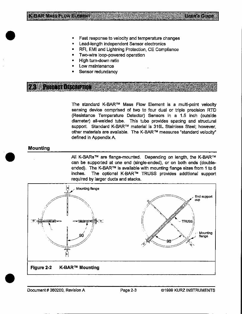
The standard K-BAR™ Mass Flow Element is a multi-point velocity sensing device comprised of two to four dual or triple precision RTD (Resistance Temperature Detector) Sensors in a 1.5 inch (outside diameter) all-welded tube. This tube provides spacing and structural support. Standard K-BAR™ material is 316L Stainless Steel; however, other materials are available. The K-BAR ™ measures "standard velocity" defined in Appendix A.
All K-BARs™ are flange-mounted. Depending on length, the K-BAR™ can be supported at one end (single-ended), or on both ends (doubleended). The K-BAR™ is available with mounting flange sizes from 1 to 6 inches. The optional K-BAR™ TRUSS provides additional support required by larger ducts and stacks.
Mounting flange
· .. ··~ ··.'·· .,.
~ /End support f;.~ ~~ /J' cup /,)':-.. '% .,
... ~> ·~, •\\
(( ' ···~ '-TRUSS~ \ >\, //
, . ·A_ // I Mounting _/'·..,,"/// flange
"---- ~ ~ ·~ 1/ ·~·~ .. ~:\
Figure 2-2 K-BAR™ Mounting
Document# 360200, Revision A Page2-3 ©1999 KURZ INSTRUMENTS
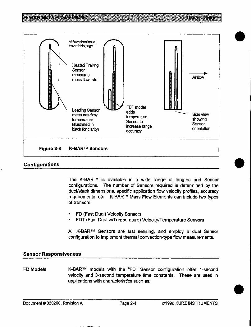
Airflow direction is toward this page
Heated Trailing Sensor measures mass flow rate
Leading Sensor measures flow temperature (illustrated in black for clarity)
Figure 2-3 K-BAR™ Sensors
FDTmodel adds temperature Sensor to increase range accuracy
Airflow
-- Sideview showing Sensor orientation
•
Configurations •
The K-BAR™ is available in a wide range of lengths and Sensor configurations. The number of Sensors required is determined by the duct/stack dimensions, specific application flow velocity profiles, accuracy requirements, etc .. K-BAR™ Mass Flow Elements can include two types of Sensors:
• FD (Fast Dual) Velocity Sensors • FDT (Fast Dual w/Temperature) Velocity/Temperature Sensors
All K-BAR™ Sensors are fast sensing, and employ a dual Sensor configuration to implement thermal convection-type flow measurements.
Sensor Responsiveness
FD Models K-BAR™ models with the "FD" Sensor configuration offer 1-second velocity and 3-second temperature time constants. These are used in applications with characteristics such as:
Document# 360200, Revision A Page2-4 ©1999 KURZ INSTRUMENTS •

•
•
•
FDT Models
Construction
• Dirty air • Fast temperature changes • Fast mass velocity changes
FD Models require one Mass Flow Computer channel per Sensor.
K-BAR™ models with the "FDT'' Sensor configuration add a separate flow temperature Sensor that has an 8-second time constant. These are used in applications with the characteristics listed above, plus the additional requirement of simultaneous temperature and flow sensing, and VelocityTemperature Mapping (VTM). VTM greatly improves temperature compensation over a wide range of flow temperatures and mass velocities. FDT Models require two Mass Flow Computer channels per Sensor.
Both the K-BAR™ 24 and K-BAR™ 24P "puffer'' probe use Metalclad™ all-welded Alloy C276 Sensors with an all-welded Sensor Support. The Temperature Sensors and Mass Rate or Velocity Sensors are individually mounted in separate tubes ("stings"), providing improved thermal isolation from the Sensor support structure, and enhanced time response to flow temperature changes.
K-BAR™ Temperature Ranges
The FD and FDT Sensors operate in a broad range of flow temperatures. K-BAR™ is available in two temperature classes:
• MT - Medium Temperatures, ranging from -40°F to +392°F (-40°C to +200°C).
• HHT - Very High Temperatures, ranging from -40°F to +932°F (-40°C to +500°C).
The HHT and air purge (P HHT) models use mineral-insulated lnconel sheathed cable for enhanced reliability. Sensor sheathing materials include 316L Stainless Steel and C276 Alloy; however, other materials and coatings are available for added abrasion and/or corrosion resistance. The Sensor Base Flange is Cb20 .
Document# 360200, Revision A Page2-5 ©1999 KURZ INSTRUMENTS
K-BAR™ Temperature Compensation
K-BAR™ Lengths
K-BAR ™ is available in several optimized temperature compensation configurations, which provide higher accuracies over a specified temperature range. Selections available are: -40°C to +125°C, ooc to 200°C, 200°C to 300°C, 300°C to 400 oc, and 400°C to 500°C. Optimization of Velocity Temperature Mapping is available at either ooc to 200°C, or ooc to 500°C.
K-BAR™ is available for either single- or double-ended mounting supports. Lengths of up to 7211 are available for single-ended mounting, or up to 120" with addition of the K-BAR™ TRUSS support option. Lengths of up to 144" are available for double-ended mounting, or up to 240" with addition of the K-BAR™ TRUSS support option.
Sensor Electronics Module
•
K-BAR™ is made up of a combination of the Sensor Bar Assembly (which • houses and supports the Sensors), and a Sensor Electronics Module.
Attached and Remote
The Sensor Electronics Module is normally mounted directly to the Sensor Bar Assembly, but in high temperature environments, the Sensor Electronics Module can be mounted remotely for protection.
Each Sensor has an independent Sensor Board within the Sensor Electronics Module that eliminates the effects of temperature variations on the output signal. This circuitry also allows the Sensor-to-Sensor Electronics cable (in remote Sensor Electronics configurations) to be shortened or lengthened without affecting the calibration.
The Sensor Boards separately transmit the signal from each Sensor in the Flow Element to the Mass Flow Computer (typically the ADAM™ 155 Series). There is one 465 Flow Sensor Board for each FD or FDT Sensor. FDT models also have one 604 Temperature Sensor Board for each FDT Sensor. FDT Models require two Mass Flow Computer channels per Sensor to accommodate the added Temperature Sensor.
There are two basic K-BARTM 24 Sensor Electronics Enclosure configurations:
• Directly Attached • Remote
Document# 360200, Revision A Page2-6 ©1999 KURZ INSTRUMENTS •

•
•
Electronics Enclosures
Cable Considerations
Protection
The Sensor Electronics Enclosure (Model 196Tx-xx) is a weatherproof enclosure is constructed of a painted aluminum body with stainless steel covers and a 1" NPT conduit hub for the 2-wire loop-powered Sensor outputs. The 2-wire total loop resistance of the cable must be less than 4 Ohms. The wire terminals accept 12 to 18 AWG wire. The operating temperature is -40°F to +140°F (-40°C to +60°C). If the operating temperature will exceed this range, the "remote" configuration (described below) should be used, where the remote-mounted electronics module can be mounted in an environment which meets these temperature requirements.
The Remote Electronics Enclosure (modei196TS-xx) allows a connecting cable length of up to 630 feet between the K-BAR™ and this enclosure (when using 12 AWG wire). You must provide braided shield cable or metal conduit for this cable. See the Installation Chapter for additional information.
If the Sensor Electronics Enclosure is exposed to lightning or EMI interference, the Mass Flow Computer must be equipped with a suitable Surge Protector. Consult the Mass Flow Computer documentation for further information.
li
I --h r------_______ ~ 1_.
(1\ Metal conduit &
1961'S-iCE or 196TS·2CE
nr----Optlonal Modet111 ~Mass Flow
~ 185 ~ . Cl / Computer
~·~'i, l ~~ / ~
Figure 2-4 K·BAR™ Electronics Module Configurations
Document# 360200, Revision A Page2-7 ©1999 KURZ INSTRUMENTS

Automatic Sensor Cleaner
Automatic Sensor Cleaner Sub-system
Applications
The K-BAR™ 24P (only) has special nozzles in the Sensor window to provide for automatically cleaning the Sensors. Cleaning is·accomplished by a short (0.1-0.3 Sec.) high-pressure blast of air (sonic velocity) directed at the Velocity and Temperature Sensors.
The supporting Automatic Sensor Cleaner sub-system consists of a Model 145 Programmable Timer, an air control Solenoid Valve, and an Air Blow-down Tank to allow periodic or on-demand cleaning.
The Air Blow-down Tank employs user-supplied compressed air at 60 to 125 PSIG {instrument quality is recommended). The average cleaning air consumption is less than 0.1 SCFM per K-BAR™ 24P. For effective cleaning, the process pressure must be less than 35% of the absolute pressure of the cleaning air source. This sub-system requires 115 or 230 VAC, 50 or 60Hz. See also Drawing 759037.
The Automatic Sensor Cleaner is important when the K-BAR™ is installed in extremely dirty stacks, or ducts having dry particulate matter that may build up on the Sensor. The Cleaner is quite effective; although it may not adequately remove wet, sticky materials, or chemicals that solidify on the Sensor. Possible applications include municipal waste incinerator ducts, cement manufacturing plants, and other extremely dirty applications where foreign material build-up proves to be a problem.
MODEL PCT-8l!NCLOSURE NSMA 4X FIBERGIA8S
-R&Ul!FVAlVi
·._ OUil.Er l"FNPI
AIR SOLENOID VALVES
Figure 2-5 K-BAR™ Automatic Sensor Cleaner (Puffer)
Document# 360200, Revision A Page 2-8 ©1999 KURZ INSTRUMENTS
•
•
•
•
•
•
Flow Profile
Varying Flow Profiles
Array Size
Sensor Back-up
K-BAR™ is available with a wide range of types and numbers of Sensors. The configuration should be determined by the duct/stack dimensions, velocity profile, and accuracy requirements.
For any duct, the ideal flow is determined from a continuous integration of the velocity in small equal-area-segments across the whole duct. This fact indicates that improvements will be seen with an increased numbers of Sensors.
The flow profile tends to be the same in the duct for each load or flow rate. If the profile is repeatable, a Correction Factor is calculated for a single Sensor at any location in the duct. To do this, an in-situ calibration is performed with a large velocity traverse data set to compute the true flow. This is then compared to the indicated velocity/flow, with the resultant ratio becoming the Correction Factor. When using the optional "Flow PerfectTM" software, the in-situ measurements and indicated measurements data are entered, then the Mass Flow Computer calculates the Correction Factor.
A duct with flow profiles that change is an ideal application for the KBAR™ Multi-Point Velocity Array. Damper positions near the Sensor (within 10 or more duct diameters), or a changing flow ratio near a duct tee are good examples where multi-point arrays are needed.
The size of the array is determined by the duct or stack size, how close the Sensors can be placed (7 inch min.), and the maximum number of Sensors that the Mass Flow Computer can read.
Another advantage of the multi-point array is Sensor back-up This works automatically with the Kurz Instruments ADAMTM 155 Series Mass Flow Computers after the in-situ calibration is done using "Flow PerfectTM".
Most applications are measured with Sensors spaced 1 to 3 feet apart on equal area circles or squares, lacking any input from a correction factor prediction etc.. The equal area locations allow a simple arithmetic average of the velocity to correctly estimate the true average of the duct
Document# 360200, Revision A Page2-9 ©1999 KURZ INSTRUMENTS
flow rate. The standard bar size permits up to four Sensors. Eight Sensors can be placed in a cross-section by using one bar on each side of a duct.
If a Sensor should fail, the system can automatically remove it from the output data and temporarily replace it by averaging the outputs of adjacent Sensors.
Multi-Point Measurement Indications
K-BAR™ TRUSS
Stack-mounting Adapters
Primary indications for a multi-point velocity measurement are:
1. Non-repeatable flow profile. Changing flow profile due to dampers, flow tees etc. is accounted automatically with a large velocity array.
2. Complex flow paths with elbows, tees, etc .. Large arrays will read the correct flow when the blockage is accounted for.
3. Sensor back-up. When used with the ADAMTM 155 Series Mass Flow Computer, a reliable flow reading is obtained even if multiple Sensors fail.
There are a variety of mounting arrangements available. The K-BAR™ TRUSS is used for larger ducts or stacks that require additional support for K-BAR™ units over 72 inches in length. There is a single-ended mounting option for an insertion length up to 72 inches, or double-ended mounting for an insertion length over 144 inches.
The standard K-BAR™ TRUSS mounting flange mates with the 1-inch flange on the K-BAR™ flow element. The K-BAR™ is inserted into the KBAR™ TRUSS after the TRUSS is installed into the stack or duct.. Standard K-BAR™ TRUSS materials are 316 Stainless Steel and Alloy C-276.
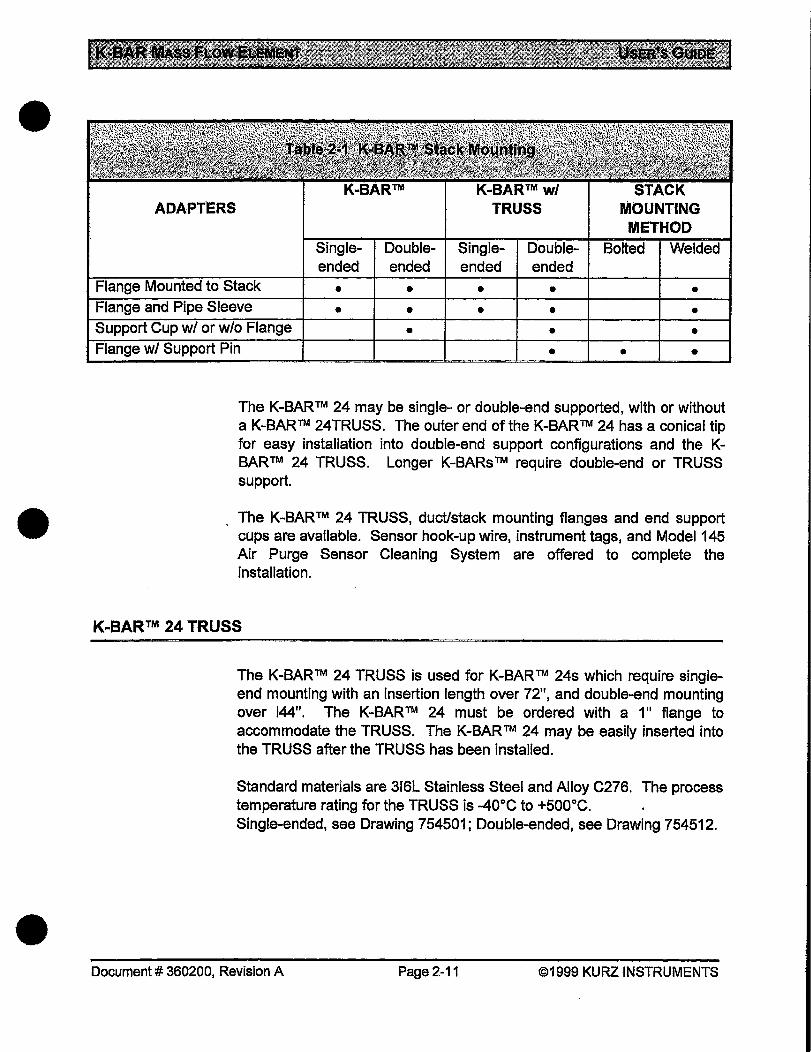
There are several stack-mounting adapters available for the K-BARTM, or K-BAR™ TRUSS. Table 2-1 summarizes the options and the stack mounting methods.
Document# 360200, Revision A Page 2-10 ©1999 KURZ INSTRUMENTS
•
•
•
•
•
•
ADAPTERS
ended ended ended ended
• • • • • • • • • •
• • • • • •
The K-BAR™ 24 may be single- or double-end supported, with or without a K-BAR™ 24TRUSS. The outer end of the K-BAR™ 24 has a conical tip for easy installation into double-end support configurations and the KBAR™ 24 TRUSS. Longer K-BARs™ require double-end or TRUSS support .
The K-BAR™ 24 TRUSS, duct/stack mounting flanges and end support cups are available. Sensor hook-up wire, instrument tags, and Model 145 Air Purge Sensor Cleaning System are offered to complete the installation.
K-BAR™ 24 TRUSS
The K-BAR™ 24 TRUSS is used for K-BAR™ 24s which require singleend mounting with an insertion length over 72", and double-end mounting over 144". The K-BAR™ 24 must be ordered with a 1" flange to accommodate the TRUSS. The K-BAR™ 24 may be easily inserted into the TRUSS after the TRUSS has been installed.
Standard materials are 316L Stainless Steel and Alloy C276. The process temperature rating for the TRUSS is -40°C to +500°C. Single-ended, see Drawing 754501; Double-ended, see Drawing 754512 .
Document# 360200, Revision A Page2-11 ©1999 KURZ INSTRUMENTS

Mounting Flanges
End Support Cup
Class 150 flat-face flanges with Schedule 40 pipe sleeves meeting mounting hole specifications of ANSI 816.5 in sizes of 1.5", 2", 3", 4", and 6".
Mounting flanges with "stud bolts" may be ordered. Standard materials are Carbon Steel, 316 SS, and Alloy C276. The process temperature rating is -40°C to +500°C. See Drawing 759016.
A conical shaped End Support Cup is available to provide double-end support. It has a 3" long by 1.61" inner diameter sleeve to receive the outer end of K-BAR™ 24 or K-BAR™ 24 TRUSS, and includes a pipe cap. Standard materials are Carbon Steel, 316L Stainless Steel, and Alloy C276. It may be ordered with or without a Class 150 F.F. flange, and may be welded or bolted directly to the outside of the duct/stack wall, or bolted to a mating flange. The process temperature rating is -40°C to +500°C. See Drawing 759017.
End Mounting Flange with Support Pin
A Class 150 F.F. flange is available with a 7/8" diameter support pin which inserts into the end support tube (1" J.D.) of the double-ended KBAR™ 24 TRUSS. Flange sizes are 1.5", 2", 3", 4", and 6". The standard materials are Carbon Steel, 316L Stainless Steel, and Alloy C276. The standard support pin length is 4". The flanges may be mounted on the inside or outside of the duct, by welding or bolting to a mating flange. The process temperature rating is -40°C to +500°C. See Drawing 759019.
Document# 360200, Revision A Page 2-12 ©1999 KURZ INSTRUMENTS
•
•
•

•
•
•
3. IPIBIIII
This section explains operation of the K-BAR™ Multi-Point Insertion Mass Flow Element.
The K-BAR™ Multi-Point Insertion Mass Flow Element is operated by an external Mass Flow Computer such as the ADAM ™ Series 155. There are no user controls or adjustments on the K-BAR™, or its external electronics module (where applicable). See the Problem Solving section for information on verifying proper operation .
Document# 360200, Revision A Page 3-1 @1999 KURZ INSTRUM8N"rS
•
•
•
4.
This section explains on-site user maintenance for the KBAR™ Multi-Point Insertion Mass Flow Element
The following information will aid you in maintenance planning, which will help ensure that you receive maximum results and uptime from your KBAR ™. Please review the warnings and cautions at the beginning of this Guide before performing any maintenance operations.
Technician Qualifications
Even minor repairs can require electronic components or w1nng connections to be replaced or repaired. Only certified electrical technicians, familiar with electronic test equipment and measurements should perform these repairs. Kurz Instruments® offers professionally conducted training for your technical staff.
Kurz Instruments ™ provides technical assistance over the phone or by email to qualified repair personnel. For information, contact Customer Service:
• Telephone (toll-free): (800) 424-7356, ext. 319 • Fax: (831) 646-1033 • E-mail: [email protected]
For major repairs, return the unit to Kurz Instruments ™ .
Sensor Replacement
Individual Sensors are not field-replaceable units - the K-BAR™ must be returned to Kurz Instruments ™ for refurbishment
Document# 360200, Revision A Page4-1 ©1999 KURZ INSTRUMENTS
In-Warranty Repair
Calibration
To protect your warranty coverage, you must have written authorization from Kurz Instruments, Inc. to perform warranty service. Contact the Customer Service number listed above for further information. Only a certified electrical technician should perform warranty service.
Annual calibrations are recommended to maintain NISTtraceability on the instrument calibration. Kurz Instruments ™ can provide this service for you. If the unit requires re-calibration while under warranty, contact Kurz Instruments® Customer Service. Additional information on calibration is listed later in this chapter.
For installations where the K-BAR™ is a critical item in maintaining your site in an operational status, you may find it prudent to stock a spare KBAR™. In such cases, this spare unit can be exchanged for in-service units when calibration is required.
Minor routine maintenance on the mechanical and electronic configurations of the K-BAR ™ include:
• Cleaning the Sensors and Flow Body, (as needed) • Verifying Sensor Electronics output signals
When K-BAR™ is first installed, or if the environment into which it is installed changes, the K-BAR™ should be monitored in order to determine cleaning and calibration schedule requirements.
Always remove all power before dismantling the system for repair, re-calibration, or cleaning!
IMPORTANT
•
•
Whenever removing the K-BAR™ (or associated mounting hardware), ensure that the equipment is replaced in its proper orientation to ensure • proper operation.
Document# 360200, Revision A Page4-2 ©1999 KURZ INSTRUMENTS

•
•
•
Techniques
Dry Powdered Dirt
Sticky Dirt
After initial installation, examine the Sensors and the Flow Body periodically to establish a cleaning schedule that suits your particular application. When the Sensor is operating in particularly dirty or particleladen environments, inspect it for cleanliness more frequently.
If the Sensors and/or Flow Body require cleaning, use processes that effectively clean it without damaging surface finishes, material properties, or the metallurgical structure of the materials. The Sensor can be bent or broken by careless handling. A bent Sensor can fail, requiring Factory repair.
In a dry powdered dirt environment, the Sensor will reach a steady state dust load. It should then be field calibrated with this level of dirt on the Sensor .
Periodic cleaning is recommended for sticky dirt that builds up over time for the best results. Despite the above, the tolerance for dirt (in contrast to turbines or Pitot tubes) is a major reason why the thermal anemometer is a such a useful and reliable industrial product.
Use of a stiff hairbrush with soap is recommended to clean the Sensor. Cleaners that are more aggressive are used at your own risk. Be careful not to bend the Sensor elements as this can change the calibration or damage the unit. Corrosion of the Sensor probe or Probe Support will eventually result in contamination entering the Sensor or Electronics Module, which will cause a failure of the unit.
Always make sure that the Sensor is dry before reinserting Into a monitoring system.
PRECAUTION
Whenever removing the K-BAR™ (or associated mounting hardware) ensure that the equipment is replaced in its proper orientation to ensure proper operation.
Document# 360200, Revision A Page4-3 ©1999 KURZ INSTRUMENTS
Please refer to the information in the following Problem Solving Chapter for ~nstructions on verifying Sensor Electronics output signals.
K-BAR™ is powered by a 24 VDC power supply which is normally sourced from the Mass Flow Computer, since that power source also provides the measurement current loops which are monitored by that computer.
The 24 VDC power is a nominal voltage (18 V min. up to 200 oc, 24 V min. up to 500 oc), since all circuits have a regulated supply and will work between 18 and 28 VDC. You may use an unregulated power supply with 50 to 60 Hz ripple as long as the instantaneous voltage remains between 18 and 28 VDC. Surge currents during Sensor warm-up could require up to 660 mA, but will decrease after the Sensor warms up (about 30 seconds). At zero flow, the current will be about 200 mA, and about 500 mA for high flow rates (12,000 SFPM). The power input is protected against reverse polarity, so if no current is flowing or there is no output signal, check the polarity against the appropriate wiring diagram in Chapter 11.
The Sensor Electronics Module is isolated from ground to avoid ground loop currents. The 24 VDC power has MOVs (metal oxide varistors) to clamp voltage spikes. These are 39 V nominal· (voltage level at 1 rnA) and do not conduct significant current below about +/- 30 VDC relative to ground. Consequently, the 24 VDC power should be grounded to prevent leakage currents on the MOVs.
Annual calibrations are recommended to maintain NISTtraceability on KBAR™ calibration. There are several approaches that can be taken to accomplish this in the field:
• Stoichiometric relationship • Velocity traverse • Tracer gas dilution
Document# 360200, Revision A Page4-4 ©1999 KURZ INSTRUMENTS
. ------- ----- ---------·
•
•
•
•
•
•
Traceable transfer standards and valid procedures must be employed in order to maintain traceability using these methods in the field.
Additionally, the unit can be returned to Kurz Instruments ™ Customer Service for certified· Wind Tunnel calibration as specified later in this section.
Calibration Strategies
Field Calibration
Flow Perfecfl'M
Calibration strategies vary depending on the cleaning schedule of the Sensor (is the Sensor clean, does it have a typical dirt load, or a maximum dirt load just prior to cleaning). Observing these considerations helps to establish the bounds on the calibration errors and/or provides the data to compensate for the dirt over time. The effect of the addition of most dirt to a thermal anemometer is reduction of the reading for the same flow rate. The best way to establish the impact of dirt on measurements and calibration is to check the Sensor's in-situ calibration against a known reference (second unit or method).
If Field Calibration data are available for the measured environment, it can be entered into the Mass Flow Computer as a correction factor, at flow xx, for up to seven flow rates.
Alternately, the optional "Flow Perfect™ "software can be used, where the observed flow rate on the element and the reference rate are entered for up to four rates. In this case, the Mass Flow Computer will calculate the correction factor. Flow Perfect™ has the advantage for multi-point arrays of re-computing the proper correction factor even if a Sensor becomes defective. It re-computes the correction factor based on the reading of the remaining good signals.
Stoichiometric Relationship
Stoichiometric techniques may be able to be used for in-situ calibration when the chemistry of the measured flow content and the amount of other reactants are known. When the specifics of the input gases are known, the output can be calculated and used as a cross-check to validate the flow readings measured using the K-BAR™ and its associated Mass Flow Computer .
Document# 360200, Revision A Page4-5 ©1999 KURZ INSTRUMENTS

Tracer Gas Dilution
Velocity Traverse
Kurz Instruments offers in-situ flow calibrations which account for all the profile issues, etc.. The tracer gas injection flow rate is measured at a known injection concentration. The diluted· concentration is then measured with an analyzer, and the unknown flow is then calculated. This method is described under Kurz Instruments Document Number 364011. Both flow profile traversing and tracer gas calibrations are available through the Customer Service department.
Velocity Traverse is a method of field calibration using a factory calibrated standard velocity signal. This can be used to help establish the volumetric or mass flow calibration. A point velocity measurement can be used to traverse the duct with equal area measurements, then average the readings. The ratio between the indicated reading where the Sensor sits and the average computed is the Correction Factor to use.
This method requires the use of a portable Sensor such as an Insertiontype Thermal Flow Meter. It is used to record the velocity of the entire cross-section. An S-type Pitot Tube can also be used, but its results must be converted from actual velocity to standard velocity (see Appendix A for details). This requires measurement of actual temperature and actual pressure in addition to differential pressure.
Of the field methods described above, the most popular is "Velocity Traverse".
Factory Calibration Method
Transfer Standard
Ducted Section
Two methods of velocity calibration are available, depending on the gas type to be calibrated.
A Transfer Standard is used for air calibrations and gas correlations, where the unit under calibration and the standard are in the same plane, perpendicular to flow. The Wind Tunnel has a relatively flat velocity profile; therefore locating both the unit and the Transfer Standard in the same sensing plane automatically accounts for Sensor blockage.
For other gases, a special ducted section on a Mass Flow Calibration System is used. In this method, the Sensor blockage and effective area of the calibration section are used to convert the mass flow to mass flow per unit area, or Standard Velocity.
Document# 360200, Revision A Page4-6 ©1999 KURZ INSTRUMENTS
•
•
•

•
•
These mass flow calibrations are generally performed at room temperature and pressure, but can be performed at elevated temperatures to account for temperature-dependent viscosity induced errors.
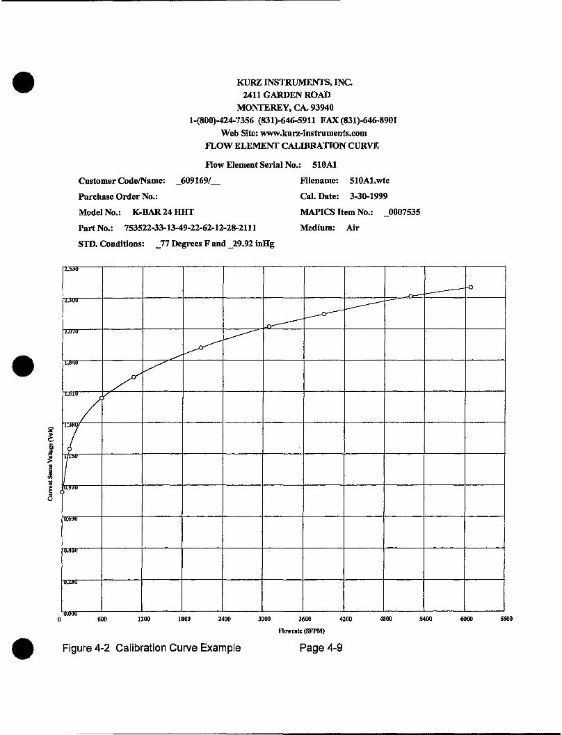
Figures 4-1 and 4-2 show a typical calibration data sheet, and a graph of the Sensor response versus Standard Velocity.
PRECAUTION
A Sensor contaminated by foreign matter (dirt, etc.) can cause erroneous readings, giving the impression that the unit has failed or is "out of calibration". Furthermore, units undergoing calibration under these conditions may yield erroneous results later, when the intrusive material becomes dislodged or is removed.
Calibration Reports
Documents
Implementation
Thermal anemometers output a voltage or current signal relative to the mass flow they are measuring; however there is a non-linear relationship between mass flow and output signal. Therefore it is necessary to develop a correction curve using precision metrology techniques (which are traceable to NIST}. Kurz Instruments™ places each flow element into a precisely controlled flow environment, such as a wind tunnel, along with a reference instrument which is calibrated by NIST. Measurements are taken at multiple mass flow rates and flow temperature levels which are in accordance with the purchase specifications for the flow element being evaluated.
The results of this evaluation are provided on two documents:
• Calibration Data and Certification Document - a text report, which includes data that, substantiates the traceability of the measurements. See Figure 4-1.
• Flow Element Calibration Curve - a graphical representation of the results, with a curve fitted to the individual measurement points. See Figure 4-2.
These data must be provided to the device which the K-BAR will feed its output signal (typically an ADAM 155 Mass Flow Computer) to enable that device to provide corrected mass flow readings. Please refer to the documentation for the Mass Flow Computer being used for information on inputting that calibration data.
Document# 360200, Revision A Page 4-7 ©1999 KURZ INSTRUMENTS

CALIBRATION DATA AND CERTIFICATION DOCUMENT KURZ INSTRUMENTS, INC
2411 GARDEN ROAD MONTEREY, CA. 93940
1-(800)-424-7356 (831)-646-5911 FAX (831)-646-8901 Web Site: www.kurz-instruments.com
SENSOR CALIBRATION DATA Serial Number/Filename: 5lOA1/510Al.wtc
Calibration Date : 3-30..1999 Customer Code/Customer Name: _609169/_
Purchase Order No. : Model No. : K-BAR 24 HHT
Part No. : 753522-33-13-49-22-62-12-28-2111 MAPICS Item No. : _0007535
Flow Units : SFPM Reference Fluid: Air
Standard Conditions(English & Metric units) : _77 Degrees F and _29.92 inHg
Point csv Velocity Velocity No. VDC SFPM SMPS
1 0.8718 0.000 o.oooo 2 1.1890 110.730 0.5625 3 1,5628 593.136 3.0130 4 1.7158 1068.277 5.4266 5 1.9315 2067.655 10.5032 6 2.0876 3083.448 15.6632 7 2.1797 3891.000 19.7653 8 2.3104 5190.871 26.3683 9 2.3769 6077.155 30.8704
NOTE: CSV is a voltage measured across _5.000 Ohm Resistor
Kurz Model 400D Wind Tunnel Calibration System FLOW ELEMENT CALIBRATION REFERENCE DATA ACQUISITION SYSTEM Model No.: 450..08, SIN: DLI7384F Model No.: LDAS-16 NIST Calibration Due Date: OS..20..1999 Serial No.: 9513-0017
This instrument was calibrated with measuring and test equi,pment with certified NIST traceability. (Copies with applicable NIST numbers are available upon request). The calibration of this instrument was performed to meet or exceed the requirements of: A. IS0-9001, B. ANSIINCSL ZS40 and C ISOIIEC GUIDE 25.
Wind Tunnel Operator:---~----------- ,Date: _________ _
Figure 4-1 Calibration Document Example
Document# 360200, Revision A Page4-8 1999 KURZ INSTRUMENTS
•
•
•
•
•
0
•
l'"""u
i.<.3UU
I"·U/U
floii'IU
KURZ INSTRUMENTS, INC. 2411 GARDEN ROAD
MONTEREY, CA. 93940 1-(800)-424-7356 (831 )-646-5911 FAX (831 )-646-8901
Web Site: www.kurz-instruments.com FLOW ELEMENT CALffiRATION CURVE
Flow Element Serial No.: SlOAt
Filename: 510A1.wtc Customer Code/Name: _609169/_
Purchase Order No.:
Model No.: K-BAR24 HHT
Part No.: 753522-33-13-49-22-62-12-28-2111
STD. Conditions: _77 Degrees F and _29.92 inHg
Cal. Date: 3-30-1999
MAPICS Item No.: _0007535
Medium: Air
~ ------~ ~
v--~
/
L v
, ... "/ v
7 l/'3U
o.~.ou
IUoO~U
IU.'IOU
1u • ...,u
u.uuu
L----f-o
600 1200 1800 2400 3000 3600
Flowrate (SFPM)
4200 4800 5400 6000
Figure 4-2 Calibration Curve Example Page4-9
6600

•
•
•
5. This section provides information on the methods used to identify and correct possible problems with the K-BAR™.
If the information in this section does not resolve your problem, please refer to a following section titled "Obtaining Assistance".
Many causes of improper or unexpected measurement results are due to factors external to the K-BAR™. Before attempting to pursue suspected equipment issues, we recommend that you check for the following external conditions.
Velocity Profile Changes
Verify that velocity profile changes are not being caused by dampers, fans, valves, etc. where the Sensor is measuring.
Sensor Insertion Location
Sensor Orientation
Verify that the K-BAR is properly located within the profile to be measured. Also, verify that there are no objects or foreign material (such as ashes, dirt, or liquid) causing Sensor interference, reducing the effective area of the measurement.
Verify that the orientation arrow on the mounting flange corresponds to flow being measured.
Calibration Validity
Verify that the K-BAWM has been calibrated to the flow medium to be measured. Take into consideration possible variations in the composition or phase of the flow medium .
Document# 360200, Revision A Page 5-1 ©1999 KURZ INSTRUMENTS

The following quick checks can be made to verify proper operation. All of these assume that the K-BAR™ is connected to a Kurz Instruments Mass Flow Computer such as the Series 155.
1. Verify that EACH Velocity input shows a voltage of between 0.8 and 2.6 volts (level depends on velocity - higher velocities give higher levels).
2. Verify that EACH Temperature input shows a voltage of between 1.0 and 5.0 volts (level depends on temperature - higher temperatures give higher levels).
3. Verify that no channel has been "kicked out", which would indicate an inappropriately high or low level from a Velocity Sensor.
•
4. Verify that temperature readings are logical values when considering • their ambient environment.
The following problem solving information assumes that the K-BAR was properly installed and operational at one point in time. When wiring is in question, it may be worthwhile to temporarily bring the K-BAR™ and the Mass Flow Computer in close proximity (if possible), and substitute a short length of known good wire for the leads that normally connect these two devices.
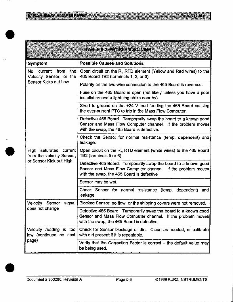
Check the following information for symptoms that match your situation, then review the related solutions for guidance in resolving your problem .
Document# 360200, Revision A Page 5-2 ©1999 KURZ INSTRUMENTS •
•
•
•
symptom Possible Causes anti Solutions
·No current from the Open circuit on the Rp RTD element (Yellow and Red wires) to the Velocity Sensor, or the 465 Board TB2 (terminals 1, 2, or 3). Sensor Kicks out Low
Polarity on the two-wire connection to the 465 Board is reversed.
Fuse on the 465 Board is open (not likely unless you have a poor installation and a lightning strike near by).
Short to ground on the +24 V lead feeding the 465 Board causing the over-current PTC to trip in the Mass Flow Computer.
Defective 465 Board. Temporarily swap the board to a known good Sensor and Mass Flow Computer channel. If the problem moves with the swap, the 465 Board is defective.
Check the Sensor for normal resistance (temp. dependent) and leakage .
High saturated current Open circuit on the Rtc RTD element (white wires) to the 465 Board from the velocity Sensor, TB2 (terminals 5 or 6). or Sensor Kick out High I-D-e-fe-c-tiv_e_4_6_5_B_oa_r_d_. _T_e_m_p_o-ra_r_il_y-sw_a_p-th-e-bo_a_r_d-to_a_kn_o_w_n_g_o_o-ldl
Velocity Sensor signal does not change
Sensor and Mass Flow Computer channel. If the problem moves with the swap, the 465 Board is defective
Sensor may be wet.
Check Sensor for normal resistance (temp. dependent) and leakage.
Blocked Sensor, no flow, or the shipping covers were not removed.
Defective 465 Board. Temporarily swap the board to a known good Sensor and Mass Flow Computer channel. If the problem moves with the swap, the 465 Board is defective.
Velocity reading is too Check for Sensor blockage or dirt. Clean as needed, or calibrate low (continued on next with dirt present if it is repeatable. page)
Verify that the Correction Factor is correct - the default value be being used .
Document# 360200, Revision A Page 5-3 ©1999 KURZ INSTRUMENTS
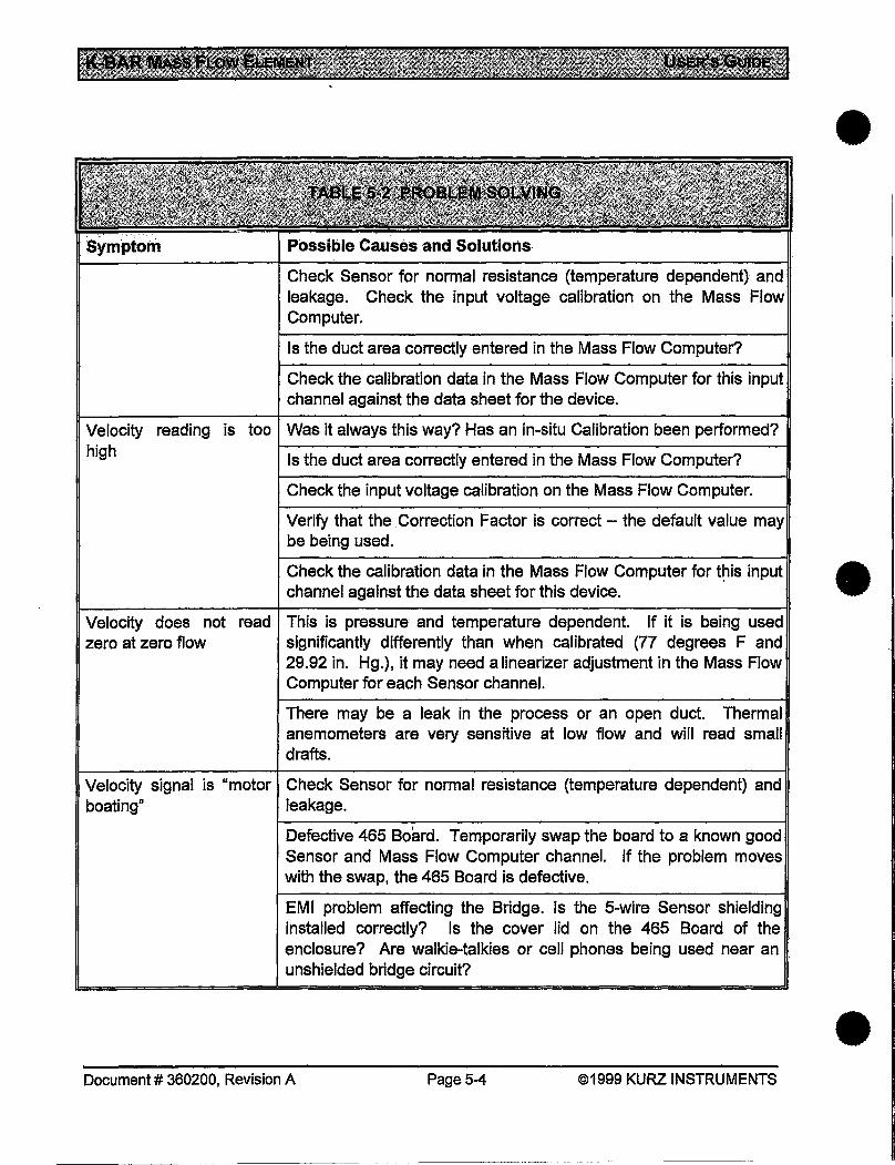
Check Sensor for normal resistance (temperature dependent) and leakage. Check the input voltage calibration on the Mass Flow Computer.
Is the duct area correctly entered in the Mass Flow Computer?
Check the calibration data in the Mass Flow Computer for this input channel against the data sheet for the device.
Velocity reading is too Was it always this way? Has an in-situ Calibration been performed? high Is the duct area correctly entered in the Mass Flow Computer?
Check the input voltage calibration on the Mass Flow Computer.
Verify that the Correction Factor is correct- the default value may be being used.
•
Check the calibration data in the Mass Flow Computer for t~is input • channel against the data sheet for this device.
Velocity does not read zero at zero flow
This is pressure· and temperature dependent. If it is being used significantly differently than when calibrated (77 degrees F and 29.92 in. Hg.), it may need a linearizer adjustment in the Mass Flow Computer for each Sensor channel.
There may be a leak in the process or an open duct. Thermal anemometers are very sensitive at low flow and will read small drafts.
Velocity signal is "motor Check Sensor for normal resistance (temperature dependent) and boating" leakage.
Defective 465 Board. Temporarily swap the board to a known good Sensor and Mass Flow Computer channel. If the problem moves with the swap, the 465 Board is defective.
EMI problem affecting the Bridge. Is the 5-wire Sensor shielding installed correctly? Is the cover lid on the 465 Board of the enclosure? Are walkie-talkies or cell phones being used near an unshielded bridge circuit?
Document# 360200, Revision A Page 5-4 ©1999 KURZ INSTRUMENTS •
•
••
•
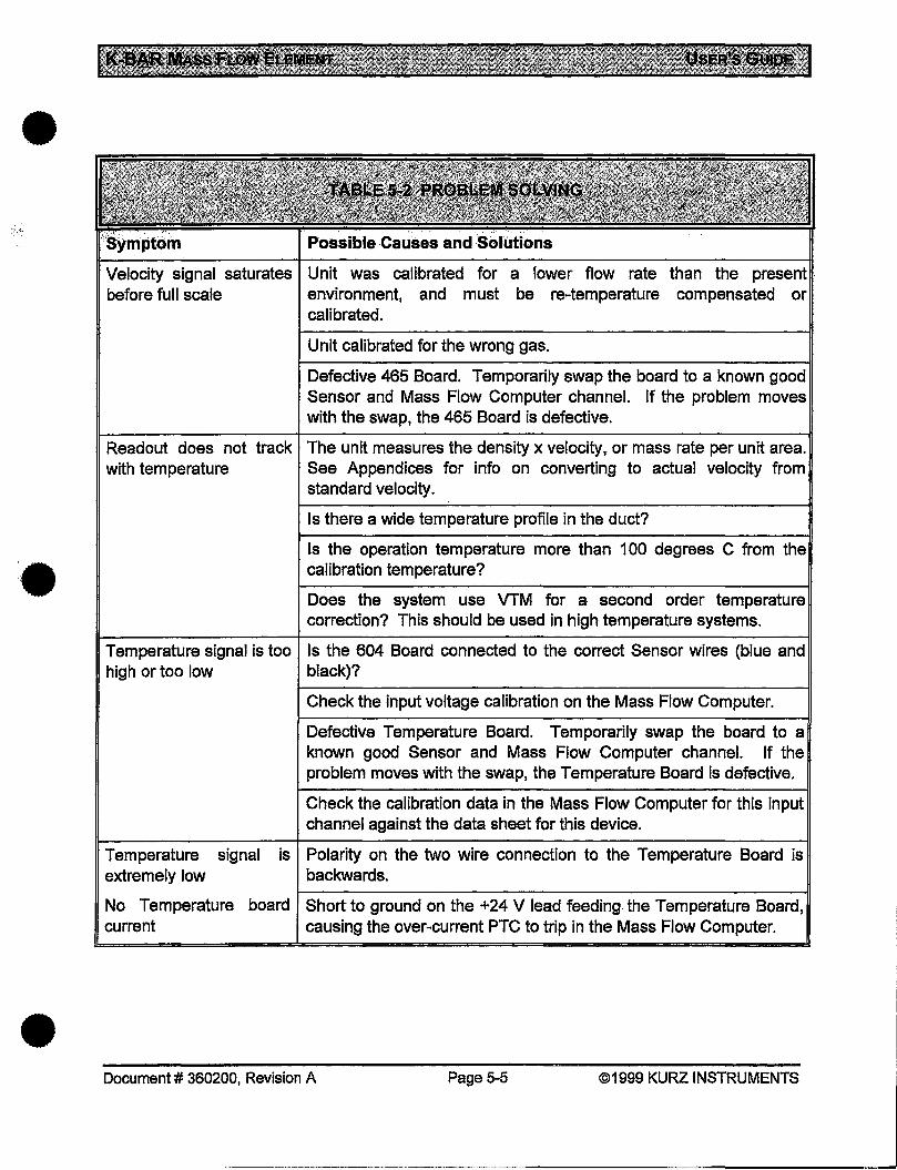
Velocity signal saturates Unit was calibrated for a lower flow rate than the present . before full scale environment, and must be re-temperature compensated or
calibrated.
Unit calibrated for the wrong gas.
Defective 465 Board. Temporarily swap the board to a known good Sensor and Mass Flow Computer channel. If the problem moves with the swap, the 465 Board is defective.
Readout does not track The unit measures the density x velocity. or mass rate per unit area. with temperature See Appendices for info on converting to actual velocity from
standard velocity.
Temperature signal is too high or too low
Is there a wide temperature profile in the duct?
Is the operation temperature more than 1 00 degrees C from the calibration temperature?
Does the system use VTM for a second order temperature correction? This should be used in high temperature systems.
Is the 604 Board connected to the correct Sensor wires (blue and black)?
Check the input voltage calibration on the Mass Flow Computer.
Defective Temperature Board. Temporarily swap the board to a known good Sensor and Mass Flow Computer channel. If the problem moves with the swap, the Temperature Board is defective.
Check the calibration data in the Mass Flow Computer for this input channel against the data sheet for this device.
Temperature signal is Polarity on the two wire connection to the Temperature Board is extremely low backwards.
~--------------------------------------------~1 No Temperature board Short to ground on the +24 V lead feeding the Temperature Board, current causing the over-current PTC to trip in the Mass Flow Computer .
Document# 360200, Revision A Page 5-5 ©1999 KURZ INSTRUMENTS
·--~---~-- -- ~---·--·---------------------------------'
Possible Causes and Solutions
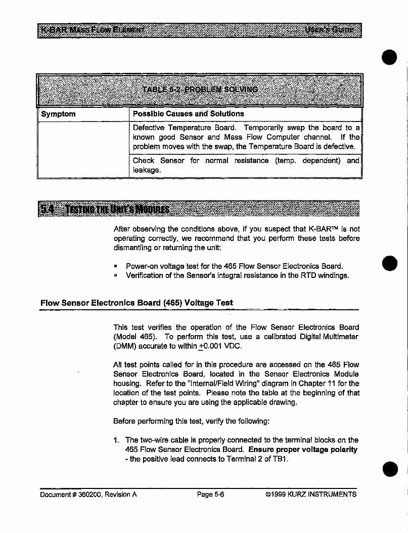
Defective Temperature Board. Temporarily swap the board to a known good Sensor and Mass Flow Computer channel. If the problem moves with the swap, the Temperature Board is defective.
Check Sensor for normal resistance (temp. dependent) and leakage.
After observing the conditions above, if you suspect that K-BAR™ is not operating correctly, we recommend that you perform these tests before dismantling or returning the unit:
•
• Power-on voltage test for the 465 Flow Sensor Electronics Board. • = Verification of the Sensor's integral resistance in the RTD windings.
Flow Sensor Electronics Board (465) Voltage Test
This test verifies the operation of the Flow Sensor Electronics Board (Model 465). To perform this test, use a calibrated Digital Multimeter (DMM) accurate to within _!0.001 VDC.
All test points called for in this procedure are accessed on the 465 Flow Sensor Electronics Board, located in the Sensor Electronics Module housing. Refer to the "Internal/Field Wiring" diagram in Chapter 11 for the location of the test points. Please note the table at the beginning of that chapter to ensure you are using the applicable drawing.
Before performing this test, verify the following:
1. The two-wire cable is properly connected to the terminal blocks on the 465 Flow Sensor Electronics Board. Ensure proper voltage polarity -the positive lead connects to Terrninal2 of TB1.
Document# 360200, Revision A Page 5-6 ©1999 KURZ INSTRUMENTS •
•
•
•
2. The Sensor's five-wire cable connects properly to the appropriate terminal blocks on the 465 Flow Sensor Electronics Board.
With a "Close Remote" Sensor Electronics Module configuration, the Swire extension cable of each Sensor must be properly connected to the Terminal Junction Box en route to the appropriate terminals on the 465 Flow Sensor Electronics Board. See the drawing referenced above for details.
Follow these instructions to verify operation of the 465 Flow Sensor Electronics Board:
1. With the power ON, check the voltage between TB1-1 and TB1-2. The voltage should be 23 VDC ~2 VDC) with TB1-2 positive in respect to TB1-1. If there is no power, check the +24 VDC power supply and its AC power source. In most cases, this will be sourced by the Kurz Instruments® Mass Flow Computer module.
2. Check the current-return signal from TB1-1. The current-return signal varies with the flow velocity. Depending on the flow that the Sensor measures, the current should range from 1 00 to 600 mA (with higher currents occurring at higher flow rates.
NOTE: It is normal for this board to produce a current surge when power is first applied, to bring the RTD up to its initial heated level. After that level is attained, current should be reduced to the normal range specified above.
Temperature Sensor Electronics Board (604) Current Test (K-BAR with FDT)
This test verifies the operation of the Temperature Sensor Electronics Board (Model 604). This board provides a current loop signal that varies from 4 mA at 0 oc to 20 mA at 500 °C.
To perform this test:
1. Disconnect the RTD input leads at TB2-1 and TB2-2 of the 604 board. See the diagrams in Chapter 11 for locations.
2. Connect a precision 100-ohm resistor from TB2-1 to TB2-2 .
Document# 360200, Revision A Page 5-7 ©1999 KURZ INSTRUMENTS
3. Disconnect the lead at TB1-1, then connect a DMM set to measure up to 20 rnA between that loose lead and TB1-1 (in series- to measure current).
4. 4.0 rnA should be observed.
5. Replace the 1 00-ohm resistor with a 200-ohm precision resistor.
6. 12.8 mA should be observed.
7. Remove the meter. Replace the wire at TB1-1. Replace the RTD leads at TB2-1 and TB2-2.
If improper readings were observed, the 604 Board must be replaced; however doing so requires that the Board/Sensor combination be recalibrated (since they are a matched set), and that new calibration data be entered into the Mass Flow Computer. In such cases, please remove the K-BAR™ Electronics Module Cover nearest the side where the wiring port is located and note the serial number on the 604 Board before calling for assistance. The serial number is written over a white background on the circuit board. ·
RTD Resistance Verification Test
Test the RTD resistance if the Sensor is questionable. A damaged Sensor will have substantially different values than those listed below.
Follow these instructions to verify the RTD winding's resistance:
1. Make note of the 5-wire cable orientation (wire-to-terminal).
2. With the power OFF, remove the Sensor's five-wire cable from TB2 on the 465 Flow Sensor Electronics Board.
See the "lnternaVField Wiring" diagram in Chapter 11.
3. Measure the resistance of the windings. Table 5-1 lists the resistance values for the RTD windings. A long 5-wire cable may increase the resistance values by up to 2 ohms.
4. Reconnect the Sensor's 5-wire cable to the 465 Flow Sensor Electronics Board. (See the technical drawings in Chapter 11).
Document# 360200, Revision A Page 5-8 ©1999 KURZ INSTRUMENTS
•
•
•
•
•
•
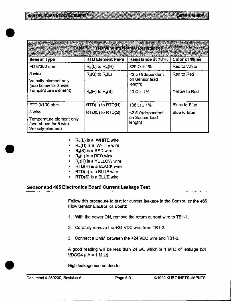
FD 9/300 ohm Rtc(L) to Rtc(H) 329 n ± 1% - Red to White r-------------,_------------~----------~
5 wire Rp(S) to Rp(L) <2.5 Q(dependent Red to Red Velocity element only on Sensor lead (see below for 3 wire length) Temperature element) Rp(H) to Rp{S) 10 n ± 1% Yellow to Red
FTD 9/1 00 ohm RTD(L) to RTD(H) 1 08 Q ± 1% Black to Blue r-------------~------------~------------~
3 wire RTD(L) to RTD(S) <2.5 Q(dependent Blue to Blue Temperature element only on Sensor lead (see above for 5 wire length) Velocity element)
• Rtc(L) is a WHITE wire • Rtc(H) is a WHITE wire • Rp(S) is a RED wire • Rp(L) is a RED wire • Rp(H) is a YELLOW wire • RTD(H) is a BLACK wire • RTD{L) is a BLUE wire • RTD(S) is a BLUE wire
Sensor and 465 Electronics Board Current Leakage Test
Follow this procedure to test for current leakage in the Sensor, or the 465 Flow Sensor Electronics Board:
1. With the power ON, remove the return current wire to TB1-1.
2. Carefully remove the +24 VDC wire from TB1-2.
3. Connect a DMM between the +24 VDC wire and TB1-2.
A good reading will be less than 24 J.IA, which is 1 M n of leakage (24 VDC/24 p. A = 1 M Q) .
High leakage can be due to:
Document# 360200, Revision A Page 5-9 ©1999 KURZ INSTRUMENTS
. ----------------------------------------1
•
•
•
6. REPLACEMENT PARTS
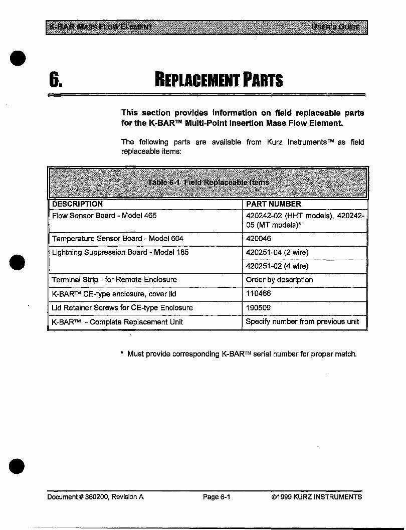
This section provides information on field replaceable parts for the K-BAR™ Ma:ilti-Point Insertion Mass Flow Element.
The following parts are available from Kurz Instruments™ as field replaceable items:
Flow Sensor Board - Model 465
Temperature Sensor Board- Model604
Lightning Suppression Board - Model 185
Terminal Strip- for Remote Enclosure
K-BAR™ CE-type enclosure, cover lid
Lid Retainer Screws for CE-type Enclosure
K-BAR™ - Complete Replacement Unit
420242-02 (HHT models), 420242-05 (MT models)*
420046
420251-04 (2 wire)
420251-02 (4 wire)
Order by description
110466
190509
Specify number from previous unit
* Must provide corresponding K-BAR™ serial number for proper match .
Document# 360200, Revision A Page 6-1 ©1999 KURZ INSTRUMENTS
•
•
•
1.
This section explains the theory of operation for the K-BAR™ Multi-Point Insertion Mass Flow Element.
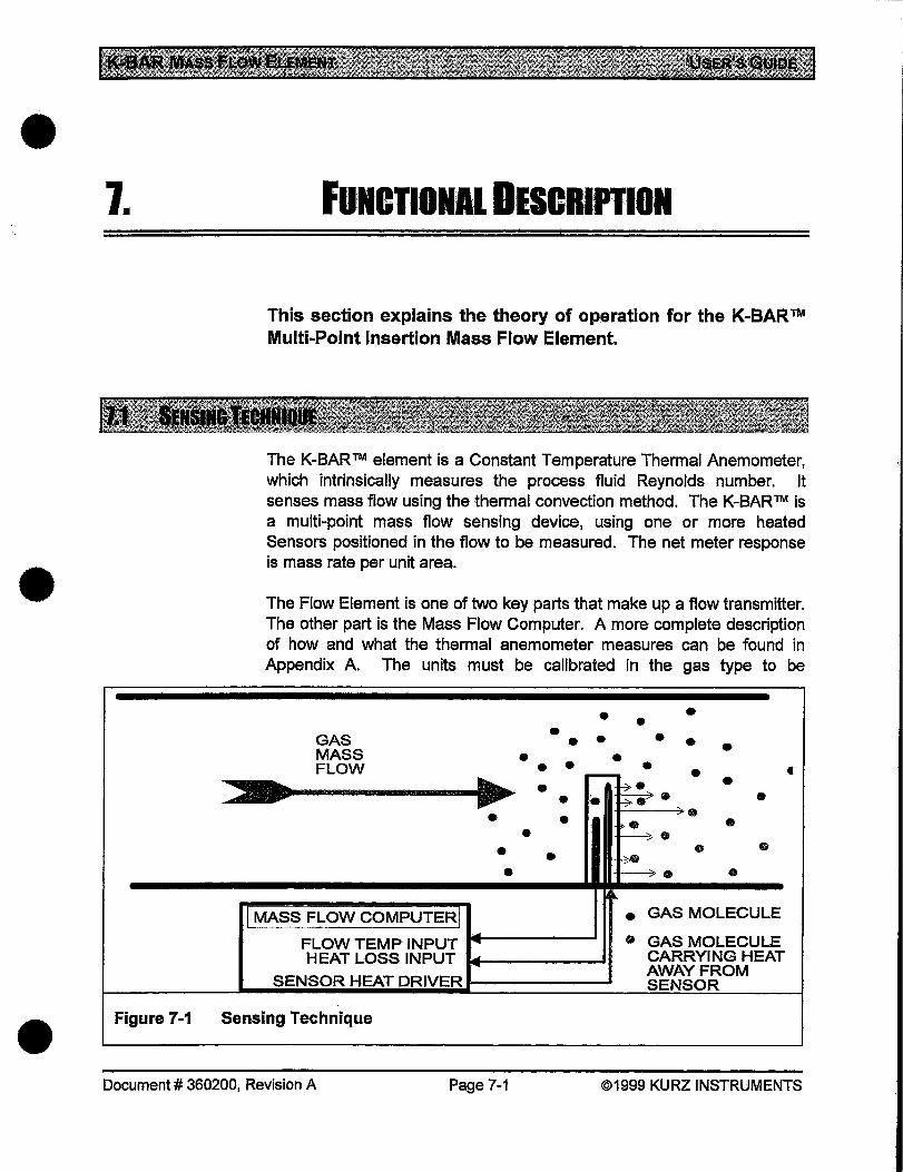
The K-BAR™ element is a Constant Temperature Thermal Anemometer, which intrinsically measures the process fluid Reynolds number. It senses mass flow using the thermal convection method. The K-BAR™ is a multi-point mass flow sensing device, using one or more heated Sensors positioned .in the flow to be measured. The net meter response is mass rate per unit area .
The Flow Element is one of two key parts that make up a flow transmitter. The other part is the Mass Flow Computer. A more complete description of how and what the thermal anemometer measures can be found in Appendix A. The units must be calibrated in the gas type to be
GAS MASS FLOW
MASS FLOW COMPUTER
• • •
•
•
• • • • • • • •
• •
FLOW TEMP INPUT HEATLOSSINPUT ~--------~
SENSOR HEAT DRIVER
•
• • • • • • • t • • •
'· . • • • •
~
• • e GAS MOLECULE
• GAS MOLECULE CARRYING HEAT AWAY FROM SENSOR
Figure 7-1 Sensing Technique
Document# 360200, Revision A Page 7-1 ©1999 KURZ INSTRUMENTS
measured, or may be correlated from Air calibrations if available.
A heating element is included in the Sensor assembly, which heats the Sensor to a pre-determined elevated temperature (significantly above the ambient flow temperature). Flow across this Sensor has a cooling effect on it. The control circuitry for the Sensor then increases the current into the heating element to maintain the Sensor at its pre-determined (elevated) temperature.
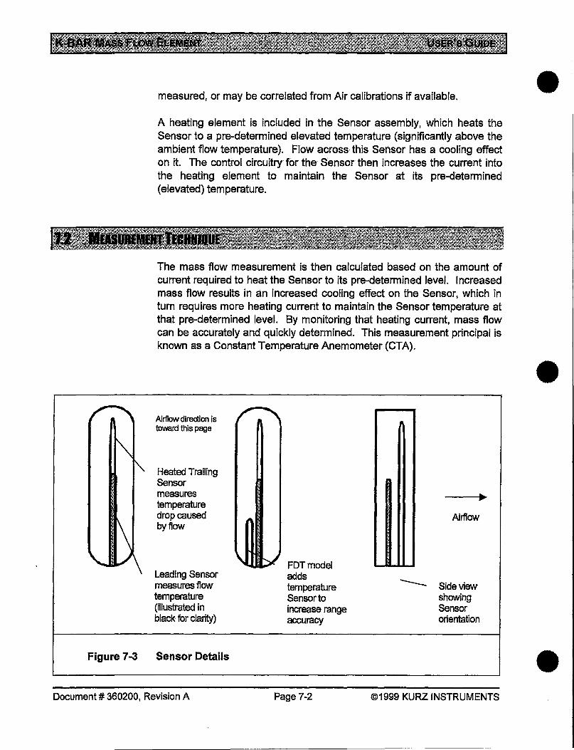
The mass flow measurement is then calculated based on the amount of current required to heat the Sensor to its pre-determined level. Increased mass flow results in an increased cooling effect on the Sensor, which in turn requires more heating current to maintain the Sensor temperature at that pre-determined level. By monitoring that heating current, mass flow can be accurately and quickly determined. This measurement principal is known as a Constant Temperature Anemometer {CTA).
Airflow direction is toward this page
Heated Trailing Sensor measures temperature drop caused by flow
leading Sensor measures flow temperature (illustrated in black for clarity)
Figure 7-3 Sensor Details
Document# 360200, Revision A
FDTmodel adds temperature Sensor to increase range accuracy
Page 7-2
Airflow
-- Sideview showing Sensor orientation
©1999 KURZ INSTRUMENTS
•
•
•
•
•
•
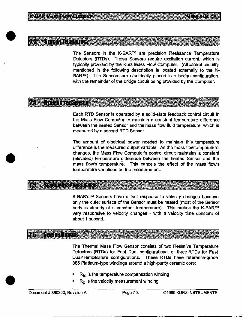
The Sensors in the K-BAR ™ are precision . Resistance Temperature Detectors (RTDs). These Sensors require excitation current, which is typically provided by the Kurz Mass Flow Computer. {All control circuitry
. mentioned in the following description is located externally to the KBAR™). The Sensors are electrically placed in a bridge configuration, with the remainder of the bridge circuit being provided by the Computer.
Each RTD Sensor is operated by a solid-state feedback control circuit in the Mass Flow Computer to maintain a constant temperature difference between the heated Sensor and the mass flow fluid temperature, which is measured by a second RTD Sensor.
The amount of electrical power needed to maintain this temperature difference is the measured output variable. As the mass flowtemperature changes, the Mass Flow Computer's control circuit maintains a constant (elevated) temperature difference between the heated Sensor and the mass flow's temperature. This cancels the effect of the mass flow's temperature variations on the measurement.
K-BAR's ™ Sensors have a fast response to velocity changes because only the outer surface of the Sensor must be heated {most of the Sensor body is already at a constant temperature). This makes the K-BAR™ very responsive to velocity changes - with a velocity time constant of about 1 second.
The Thermal Mass Flow Sensor consists of two Resistive Temperature Detectors (RTDs) for Fast Dual configurations, or three RTDs for Fast Dual/Temperature configurations. These RTDs have reference-grade 385 Platinum-type windings around a high-purity ceramic core:
• Rtc is the temperature compensation winding
• Rp is the velocity measurement winding
Document# 360200, Revision A Page7-3 ©1999 KURZ INSTRUMENTS
·-----····------···-----------·-------~~-----~=------~~
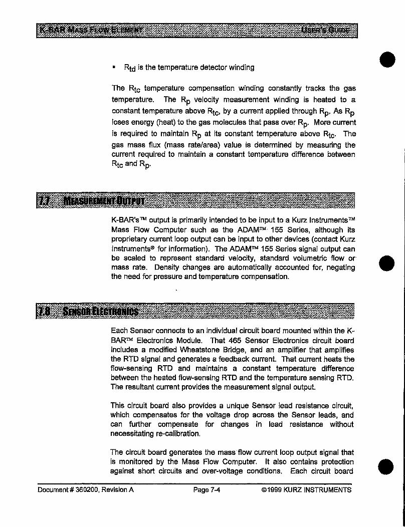
• Rtd is the temperature detector winding
The Rtc temperature compensation winding constantly tracks the gas
temperature. The Rp velocity measurement winding is heated to a
constant temperature above Rtc• by a current applied through Rp. As Rp
loses energy (heat) to the gas molecules that pass over Rp. More current
is required to maintain Rp at its constant temperature above Rtc· The
gas mass flux (mass rate/area) value is determined by measuring the current required to maintain a constant temperature difference between Rtc and Rp.
K-BAR's ™ output is primarily intended to be input to a Kurz Instruments ™ Mass Flow Computer such as the ADAM™ 155 Series, although its proprietary current loop output can be input to other devices (contact Kurz Instruments® for information). The ADAM™ 155 Series signal output-can be scaled to represent standard velocity, standard volumetric flow or· mass rate. Density changes are automatically accounted for, negating the need for pressure and temperature compensation.
Each Sensor connects to an individual circuit board mounted within the KBAR™ Electronics Module. That 465 Sensor Electronics circuit board includes a modified Wheatstone Bridge, and an amplifier that amplifies the RTD signal and generates a feedback current. That current heats the flow-sensing RTD and maintains a constant temperature difference between the heated flow-sensing RTD and the temperature sensing RTD. The resultant current provides the measurement signal output.
This circuit board also provides a unique Sensor lead resistance circuit, which compensates for the voltage drop across the Sensor leads, and can further compensate for changes in lead resistance without necessitating re-calibration.
The circuit board generates the mass flow current loop output signal that is monitored by the Mass Flow Computer. It also contains protection against short circuits and over-voltage conditions. Each circuit board
Document# 360200, Revision A Page 7-4 ©1999 KURZ INSTRUMENTS
•
•
•
•
•
•
must be matched to its corresponding Sensor in order to maintain Factory calibration validity.
For additional information on Mass Flow Measurements, see Kurz Instruments ™ technical paper titled "Theory and Application of Kurz Thermal Convection Mass Flow Meters", Document# 364003 (available as a download from the Kurz Instruments® web site - www.kurzinstruments.com).
For additional information on the measurement system, see the User's Guide for the Mass Flow Computer you are using: The User's Guide for the Kurz 155 ADAM ™ Mass Flow Computer also contains a glossary of terms .
Document# 360200, 'Revision A Page7-5 ©1999 KURZ INSTRUMENTS
•
•
•
8.
WEB Support
FAX
Phone Support
Emergency Support
OBTAINING AsSISTANCE
This section explains how to obtain assistance for use of the K-BAR™ Multi-Point Insertion Mass Flow Element when the information in the previous Problem Solving section did not resolve the problem.
Kurz Instruments™ is fully committed to excellent support for your Kurz products.
NOTE: Do not use e-mail or FAX for emergency requests - see the information at the bottom of this page for instructions.
We offer support via the Internet atwww.kurz-instruments.com , or send e-mail directly to [email protected] .
For sales support, e-mail [email protected] .
If that information does not satisfy your needs, you can FAX your service needs to us at (831) 646-1033; or for sales support, (831) 646-8901.
If you obtained your product from an authorized Kurz Instruments ™ representative, you should initially contact them for support. For headquarters phone support, please contact us at (831) 646-5911 during normal business hours in the U.S. Pacific time zone. Listen carefully to the voice prompts and respond accordingly.
Emergency support is available after norma! business hours, including weekends. When you call during business hours, select "0" (zero) to reach the Operator, then inform her of your needs. If the emergency is after normal business hours, listen carefully to the voice prompts and leave a message in the Emergency mailbox. A Technician will be paged and will return your call promptly .
Document# 360200, Revision A Page 8-1 ©1999 KURZ INSTRUMENTS
•
•
•
9. IITIIRNIIG P'RIDUOIS
This section explains how to return the K-BAR™ Multi-Point Insertion Mass Flow Element for repair or other purposes.
Following this procedure will help assure that your product return is handled efficiently.
Equipment returned to Kurz Instruments ™ for warranty repair must be shipped pre-paid. Kurz Instruments ™ will return equipment under valid warranty pre-paid .
Kurz Instruments ™ requires a confirmed purchase order before performing non-warranty work. To avoid delays, please arrange this prior to returning equipment to Kurz Instruments.
To return equipment to Kurz Instruments:
1. Contact Kurz Instruments ™ to obtain a Return Material Authorization (RMA) number from Customer Service:
• Telephone (toll-free): (800) 424-7356, ext. 319 • Fax: {831) 646-1033- if busy use (831)646-8901
IMPORTANT To help ensure your equipment is properly tracked, DO NOT return any equipment without an RMA.
Document# 360200, Revision A Page 9-1 ©1999 KURZ INSTRUMENTS
2. Include a letter describing the problem. Your correspondence must include:
• The purchase order number or Kurz InstrumentsTM order number from your original invoice.
• The name, telephone, and FAX number, (including the area code and extension) of the person at your firm to contact regarding the equipment.
• The address and person to which the equipment is to be returned. • The address and person to which the repair bill should be sent. • A description of the problem, and the application conditions. • An authorization of the work, and a request for the corrections to
be performed at Kurz Instruments.
Reference all documents and correspondence to the RMA# you are assigned.
3. Return the equipment and the above report to this address:
Kurz Instruments, Inc. 2411 Garden Road Monterey, CA 93940
Attn: Customer Service
RMA #: ------
NOTE: Clean the equipment before it is returned. To do otherwise may violate laws and expose personnel to unwarranted risks. Kurz Instruments® is not equipped to clean potentially hazardous materials from returned equipment.
Document# 360200, Revision A Page 9-2 ©1999 KURZ INSTRUMENTS
•
•
•
•
•
•
This section explains how to install or relocate the K-BAR™ Multi-Point Insertion Mass Flow Element.
There are two operations involved in installation of the K-BAR™:
• Physical mounting • Electrical connections
Also, consult the documentation provided with the Mass Flow Computer to which the K-BAR™ will be connected for information on those operations. Some steps in this Installation Procedure may not apply to your configuration.
When you receive your equipment, carefully check that your order has been filled correctly and that no damage has occurred.
1. Inspect the outer packing carton for damage. If damaged, notify the Carrier at once. They are liable for such damages, including possible damage to the contents. Please also submit a report to:
Kurz Instruments, Inc. 2411 Garden Road Monterey, CA 93940 Attn: Customer Service
IF DAMAGE TO THE OUTER CARTON IS NOTED, DO NOT PROCEED UNTIL THE CARRIER HAS INSPECTED THE SHIPMENT •
Document# 360200, Revision A Page 10-1 ©1999 KURZ INSTRUMENTS
2. Check the Packing Slip provided, and verify that the carton contains all parts listed.
3. Use care to ensure that spare parts, accessories, and important documents (such as calibration certifications) are not discarded with the packing material. Save these documents and other information pertinent to your order for future reference.
If any parts are missing, contact Customer Service immediately upon receipt of the shipment:
• Telephone (toll-free): (800) 424-7356 • Fax: (831) 646-1033
The four main limiting factors to consider when selecting an installation location for K-BAR™ are:
1. Position of the K-BAWM into a suitable location within the flow to be measured, and free from condensation.
2. Temperature limits of the K-BAR™ Electronics Module (-40°C to +60°C}.
3. If the temperature will exceed item 2, above, then the K-BAR™ Electronics Module must be mounted remotely. In that case, the limit for wire length is 1n {2 n "round trip"), which is 630ft. when using 12 AWG. copper wire.
4. The K-BAR™ should be reasonably accessible for cleaning and maintenance.
The following section provides added details on these parameters.
Temperature Limitations
The ambient temperature for the K-BAR™ Electronics Module should not exceed +60 oc. If this is a problem, the Remote· Electronics configuration
•
•
should be used. The (passive) junction box used for the wiring that runs • to the remote Electronics Module will withstand up to 100 o C.
Document# 360200, Revision A Page 10-2 ©1999 KURZ INSTRUMENTS
• Remote Configuration Cabling
The 5-wire Sensor connection must use quality wire whose resistance per lead is less than 1 n. Each wire must match the resistance of the other wires within 0.010 so the Lead Length Correction Circuit will work properly. This procedure is also required to ensure the factory c~libration and temperature compensation holds up in the field. If the individual wires do not meet the matching specification, their length must be trimmed or extended until their resistance matches as specified. The terminal strips are limited to 12 AWG wire, which limits the remote configuration to about 630 ft. between Sensor and the Sensor Electronics Module.
NOTE: This refers to the wiring between the K-BAR™ Sensor Bar and its remotely mounted Electronics Module (if applicable) , not that between the Electronics Module and the Mass Flow Computer.
Shielding for EMI This wiring must be a braided shielded cable with a peripheral bonded shield in the cable glands at each end, or wiring run in a rigid conduit for the entire length in order to remain in compliance with the CE EMI rating. Armor cable or "liquid tight" flexible conduit are not adequate for EMI
• protection.
•
Condensation
The ''Transmitter Attached" electronics do not have the same EM I constraint on the wiring; however, shielded cabling I rigid conduit between the K-Bar Electronics and the Mass Flow Computer are still recommended. The wiring between the K-BAR™ Electronics Module and the Mass Flow Computer does not have a resistance-matching requirement, but should be less than 2 n per wire.
The K-BAR™ must be located where it will not be vulnerable to condensation. Water condensation or any liquid on the Sensors can result in false high readings since they have a much higher heat capacity than gasses, and require considerable energy to cause evaporation.
To avoid such situations:
1. Locate the K-BAR™ where flow temperatures are above the condensation point.
2. Orient the K-BAR™ horizontally to prevent liquid from running onto the Sensors.
Document# 360200, Revision A Page 10-3 ®1999 KURZ INSTRUMENTS

Flow Obstructions
3. Consider insulating the duct near the K-BAR™ to prevent "rain" inside the duct.
4. If the K-BAR™ may be exposed to condensation, ensure that materials used (particularly near the wall where the K-BAR™ is mounted) is made of corrosion-resistant materials. Consider adding protective shielding if necessary.
Condensation may eventually lead to corrosion, which will significantly shorten the life of the unit.
If the process being monitored has moving valves or other flow profile disturbances, keep a distance from them to obtain the best performance. As an example, Table 10-1 shows the effects of a single 90° elbow on the flow profile as measured with a single Sensor. Multi-point measurements will provide higher accuracy.
Accuracy Clear Flow- Upstream -in duct diameters
0.5% 30
2.5% 20
11% 10
Clear Flow - Downstream -in duct diameters
15
10
5
The Electronics Module should also be positioned where it is not exposed to impacts or excessive vibration.
For addition information, see "K-BAR™ Location and Sizing" in Chapter 2 .
Document# 360200, Revision A Page 10-4 ©1999 KURZ INSTRUMENTS
•
•
•
•
••
•
Procedure
This section provides an overview of the physical installation for the KBAR™ Mass Flow Element. Refer to the technical provided with your order for additional information. Each the K-BAR™ is made to order for length, sensor locations and mounting method.
Be aware of the potential hazards associated with the environment into which the equipment will be installed. Kurz Instruments ™ cannot anticipate these for you.
Please review the general warnings and cautions at the beginning of this Guide before performing any instaJI.ation operations .
Use only quality tools and materials during an installation.
Use heat and corrosion-resistant mounting hardware to help ensure that the K-BAR™ can be removed for service or calibration later.
The installation will vary according to your specific configuration; however, the mechanical installation of the K-BAR™ mass flow element will fol.low this general flow:
Document# 360200, Revision A Page 10-5 ©1999 KURZ INSTRUMENTS
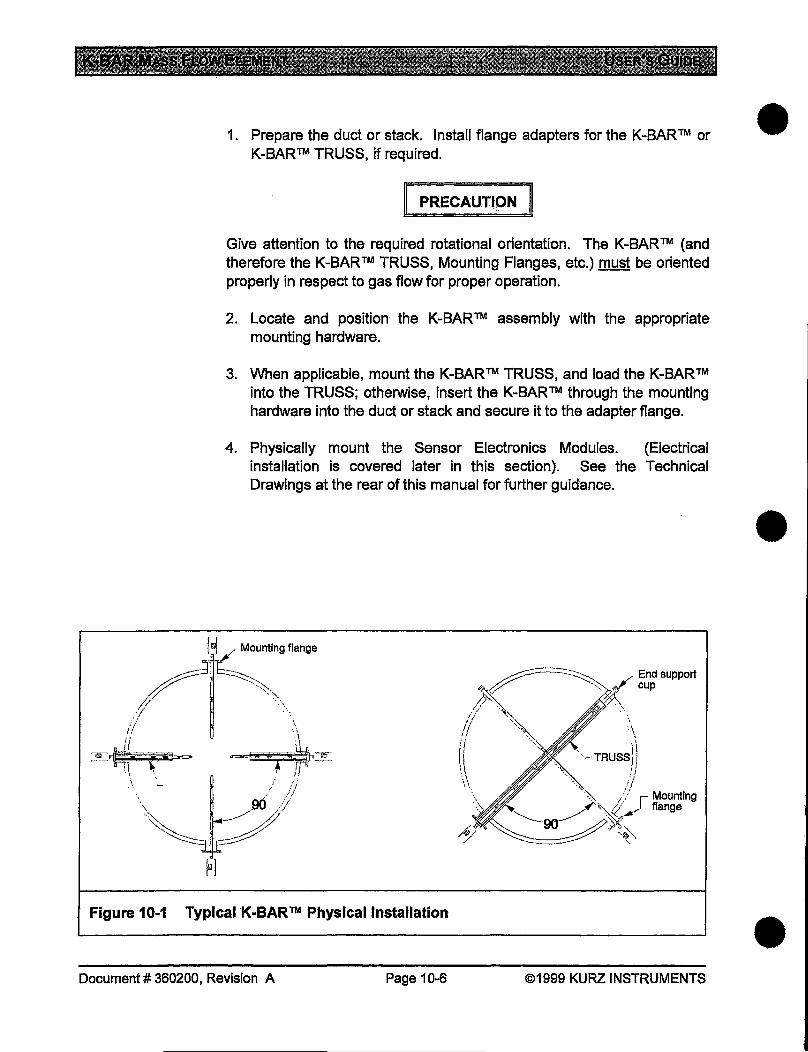
1. Prepare the duct or stack. Install flange adapters for the K-BARTM or K-BAR™ TRUSS, if required.
PRECAUTIQN
Give attention to the; required rotational orientation. The K-BAR™ (and therefore the K-BAR™ TRUSS, Mounting Flanges, etc.) must be oriented properly in respect to gas flow for proper operation.
2. Locate and position the K-BAR ™ assembly with the appropriate mounting hardware.
3. When applicable, mount the K-BAR™ TRUSS, and load the K-BAR™ into the TRUSS; otherwise, insert the K-BAR™ through the mounting hardware into the duct or stack and secure it to the adapter flange.
4. Physically mount the Sensor Electronics Modules. (Electrical installation is covered later in this section). See the Technical Drawings at the rear of this manual for further guidance.
I~ / Mounting flange
~~
'· '.\ .\
~~,~, ~~=p,_-w-.. / //
/
Figure 10-1 Typical K-BAR™ Physical Installation
Document# 360200, Revision A Page 10-6
/ End support '-., ':-c:,t cup
r. -~' ....
©1999 KURZ INSTRUMENTS
•
•
•
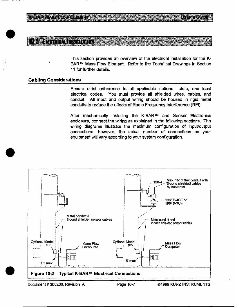
•
•
•
This section provides an overview of the electrical installation for the KBAR™ Mass Flow Element. Refer to the Technical Drawings in Section 11 for further details.
Cabling Considerations
1'1 I I
1 I i
~01 ~
Ensure strict adherence to all applicable national, state, and local electrical codes. You must provide all shielded wires, cables, and conduit. All input and output wiring should be housed in rigid metal conduits to reduce the effects of Radio Frequency Interference (RFI).
After mechanically installing the K-BAR ™ and Sensor Electronics enclosure, connect the wiring as explained in the following sections. The wiring diagrams illustrate the maximum configuration of input/output connections; however, the actual number of connections on your equipment will vary according to your system configuration .
~
j '1 190-4 Max. 15' of flex conduit with ,I '75-cond shielded cables
I 1 jn by customer
,=n~. l "' , ' 196TS-4CE or · 196TS-2CE
F==~
rl , , Metal conduit & ; II 11 2-cond shielded sensor cables ; I ·r Metal conduit and I " . I :~r/ I ! f/ 2-cond shielded sensor cables
•J' I I
I 1 I I ,, i I I I , I '
Optional Mod~e!
1/ 185 I
!
'-/
rMassFiow / Computer
Optional Model
i------1 185_
w j15'max'
I 1/ i_
Mass Flow FComputer
15' max
Figure 10-2 Typical K-BAR™ Electrical Connections
Document# 360200, Revision A Page 10-7 ©1999 KURZ INSTRUMENTS
Wiring Connections for the "Sensor.Eiectronics Module Attached" Configuration
NOTE: If your K-BAR™ does not have the Sensor Electronics Module attached, proceed to the section below.
For a K-BAR™ Transmitter Attached configuration, connect the components as follows:
1. Connect the K-BAR™ Sensor Electronics enclosure to the Mass Flow Computer, or the Termination Panel (if included).
2. Connect the Termination Panel to the Mass Flow Computer; or connect the K-BAR™ Sensor Electronics Module directly to the Mass Flow Computer as appropriate.
Proceed to the ''Verify the Wiring Connections" section, below.
Wiring Connections for the Remote Configuration
For a K-BAR™ Remote configuration, connect the components as follows:
1. Connect the K-BAR™ Junction Box to the Sensor Electronics Module enclosure. You must provide shielded cable with shield terminating cable glands or rigid conduit for the wires, as specified.
2. Connect the Sensor Electronics Module enclosure to the Mass Flow Computer, or the Termination Panel (if included).
3. Connect the Termination Panel to the Mass Flow Computer; or, connect the Sensor Electronics Module directly to the Mass Flow Computer, as appropriate.
Make certain that.you have observed the shielding requirements specified in "Determining a Suitable Location" earlier in this chapter.
Verifying the Wiring Connections
•
•
Verify the wiring connections to the K-BAR™ Mass Flow Element, as • follows:
Document# 360200, Revision A Page 10-8 ©1999 KURZ INSTRUMENTS
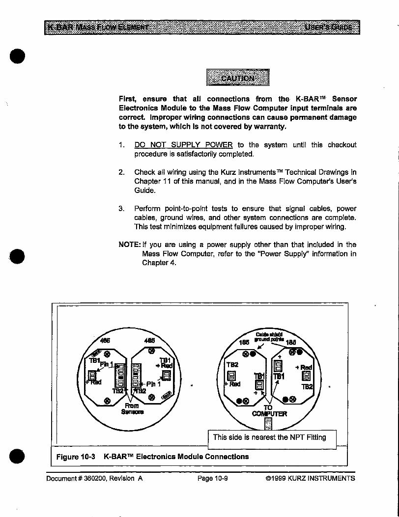
•
• ·.
First, ensure that all connections fr()m Ute K-BAR™ Sensor Electronics Module to the Mass Flow Computer input terminals are correct Improper wiring connections can cause permanent damage to the system, which is not covered by warranty.
1. DO NOT SUPPLY POWER to the system until this checkout procedure is satisfactorily completed.
2. Check all wiring using the Kurz Instruments ™ Technical Drawings in Chapter 11 of this manual, and in the Mass Flow Computer's User's Guide.
3. Perform point-to-point tests to ensure that signal cables, power cables, ground wires, and other system connections are complete. This test minimizes equipment failures caused by improper wiring.
NOTE: If you are using a power supply other than that included in the Mass Flow Computer, refer to the "Power Supply" information in Chapter4.
This side is nearest the NPT Fitting
• Figure 10-3 K-BAR™ Electronics Module Connections
Document# 360200, Revision A Page 10-9 ©1999 KURZ INSTRUMENTS
The K-BAR should be tested for proper operation before being placed into service. See the Problem Solving section for the test procedure.
After following the instructions in this section, if further assistance is needed with your installation, contact your Kurz Sales Representative, or Kurz Customer Service:
• Telephone (toll-free): (800) 424-7356 • Fax: (831) 646-1033, if busy use (831)646-8901
Document# 360200, Revision A Page 10-10 ©1999 KURZ INSTRUMENTS
•
•
•
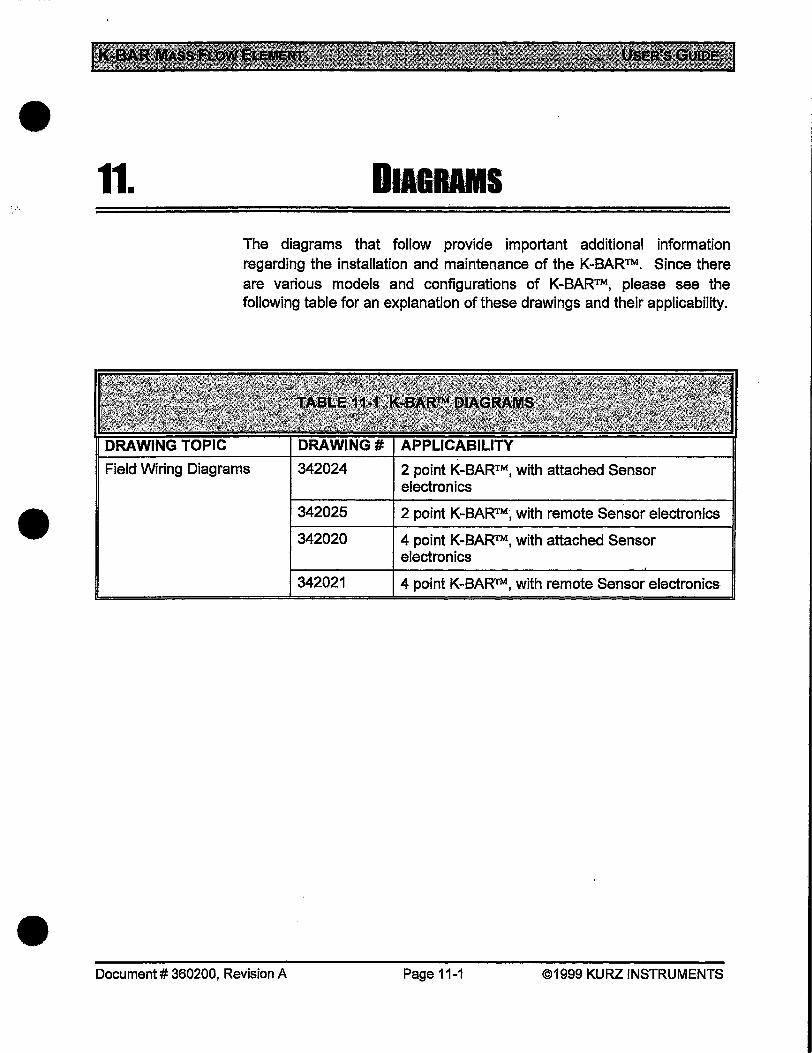
•
•
•
11. DIAGRAMS
The diagrams that follow provide important additional information regarding the installation and maintenance of the K-BAR™. Since there are various models and configurations of K-BAR™, please see the following table for an explanation of these drawings and their applicability.
Field Wiring Diagrams 342024 2 point K-BAR™, with attached Sensor electronics
342025
342020
342021
Document# 360200, Revision A
2 point K-BAR™; with remote Sensor electronics
4 point K-BAR™, with attached Sensor electronics
4 point K-BAR.TM, with remote Sensor electronics
Page 11-1 ©1999 KURZ INSTRUMENTS

7 6 5 4, 3
fMii(!UT----- ------::----------~ ---------~-----------;.::---~
: 'lll"orfof~ 'lll"orfof~ 'D•orfof~ (liP.) 'O•orfof-1 :
I . . ! 0
c
B
I I
~ ~--~-:=-----------------------------____________ .....00:~-----, 1 :r:?z n ~H ~:u :t:t u& ll~ :~::;: ~n lll n Hi I
i ~·~ .. E:PE:J E:PE:J e;JE:J !
:"~ D ii ii li D ii ! r: u u 8;. u 5;. u tt;.
'i I 4 u Jl ff J/ II J/ '
~--~-=~ ----- ttlt ----- tfft ----- H --------------------~ 11! il r-t.-~ ~~ iii~ iii I I L (hPJ :.u. :.m :.u.
G~:ry ~~ G~:ry , ffi+ V g w -SHIID~ 1
1:: y .. • y 10--. l - ~ ~ ~ ji ~ ~ -SIIIO
I ..L .. ~ ~~IJlCI~!i!!!O:.!o:•:@J_ -----------------------------------------
c
B
A :Fso.:f:J:<:z.- A
• A . -....... A m:11-PIR'IIRE(Co)
.. 12
A~-=-l'll'i:"'IO".'III£=-=:tr:L -·~1011:---~JQJ.
& IUDIIIIII_I'IIE._rr-.
8
• 6 5 4
• •
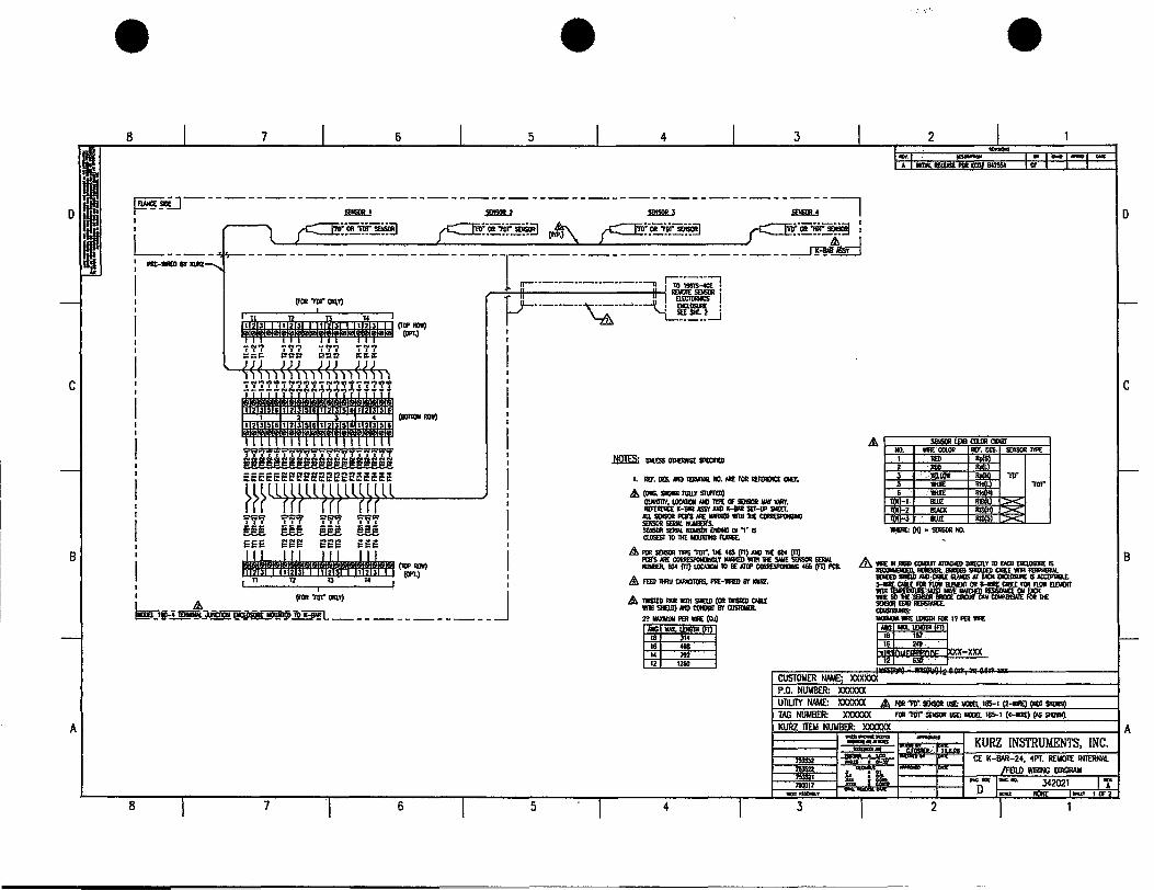
c
8
A
• • 8 7 6 5 4 3
~~_]------------~---------~----------~---------;;_:-1
Plll:-lllllli8Y --------------------r-------. --------------
r··-----.. --.. -· .. -·----u :;,·~~
p-1 II II!EWI!- . (rOB 'I'D1" ONI,l)
iW~~·~ ~OPt~ ~~~ ~Zb ~~6 ~l!
I I I 6 I I 4 (IIOTIW ROI)
I 3 6123 6123 61 56
~ ~ 9tr'l w w w ~~~ ~~~ eee ~~G
1 ~m~~~ I I 12 T3 T4 . I
I ~'I'Dt"- J (ij...i~-- - To ~----~ <-llol!l------------
8 7 6
··--·---~---·-··--tU" : == ! SEt: Sill. 2 • _____ _.J
5
.ms: liiWS OTII£RIISE S!'£CFED
I. RU. DES. MD - NO. M£ rOR RUlR£NC£ ONI.I',
£ (OIG. Sl«lllll RILLY Sliii'RD) . OllVIIllY, LOCIIDIIIO 1'tPE CF SENSOR IIAI' VN!Y.
RUlR£NC£ K-BNI ASSt MD K-BNI SEr-UP SHEET. FI:8'SM£-IIIIHII(CORII£SP(N)IIG
A~~~~-=:t=LRRML 11U1011P1. 104 (TI) UlCAIIONIO Ill: ATQP- 465 (f1) PCB.
A\. IUD 1IIRU tAPN:ITORS, Pllt:-'IIR£ll 8Y ICURZ.
£ 1IISIED PAIR wmt SHaD [OR 1IISIED tABU: wmt SllnD) NIO toiOIT 8Y CIISlOIIEII. 2? 11AX1o1U11 PER WIRE [C.)
A1IIG IIAX.lDIGTII(Fl] 18 314 16 498 14 192 12 1260
4
I
• 2
D
c
&.1 -~· "!'- I ~CXW< IR
'I'D1"
8
M I I JA
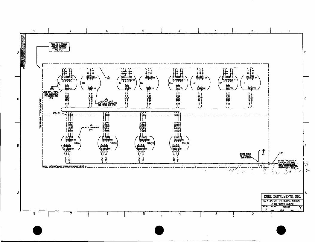
8 7 6 5 4 3 2
r~~! .---~. -10 l·IIAR '
L .. .!!.l!".:..! •• _j D
c
B 8
r---.. ------------------------------------------------------. --l T _..,..., -NIII':t _,..""t CD _ ..... l :t!:l !! t:. t:. t:. :t~Z ll 11 ~ & j;ll l:t :\ :!! ~ l!l :tJ. .l ~·:I: •
j ~ ~~ ~~~~ .. - i I ~ UJ~ ~~ C_&J~ '~ow~ '1''1' '\"\' 'l''l' '1''1' 'l''l' '1''1' 'i'~
d Fti <~:r~ II II II II II II I~ 1::
1 u u sJ< u s"' u H I
•m 9 II n fl II U II '
~---'"L=it ----- tffl ------ i ----- H --------------------~ ~15 ... - ... - .. - .. - .. - .. - .. - .. - I a sui .t. ... • .. &!"
EEE¥ r-185EMFti 8 ~~~ Hit ~!!! ¢slim (Ill'~ ~8~& ¢us ~us
c::Y (£9 (£9 I ~ m 1
7
181
185(C) m185(D) j
: n H n ~~ =~:~ ~ I,), ),\, \,\, 1,1, II .1 (REitRI
t~l&lii:----~ , ; U;-.~£'... "', """< -----~-- j]_------------------------------------.,--------- ,U .. &! 1~
/i-'1 I '<·:··, .... ~.Y::- ... :-'··;\-
c
·-. } ;.·:-~~ ..
A
I ~~ft~~~u~~~~-~A
8 7 6 5 4 3
• • •
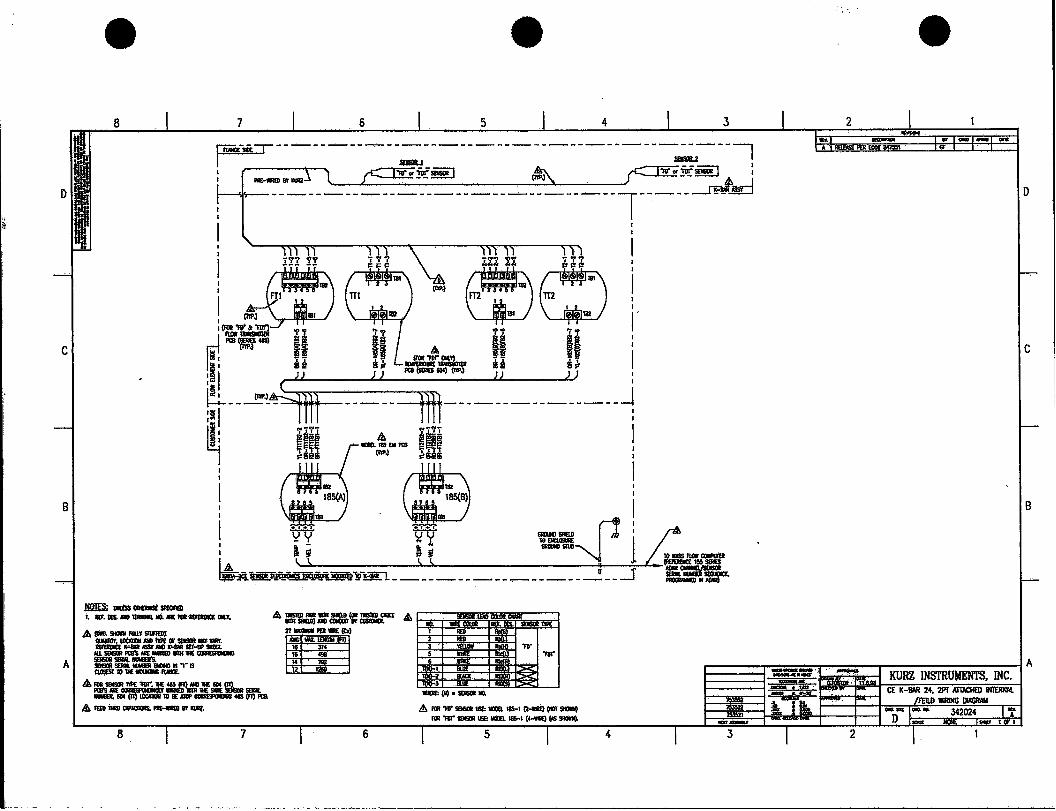
I~
c
B
A
• • 7 6 5 4 3
p---.,.---------: r -·-s 1 ~k-_~------~----------.;.----, IT-------- u -- • (l'll'J ~:!0!.:-1 : -- -- --------- ~- _) -----1-----~..!!0
~ l%l :t:t &U 181
~ ~J eiJ21
182
E:J2 I I 1 2 I
(I'll' 181 182 >
: .. ~ .• , TT 'i I r: w:~.. tt H !. I 'lj 4 U I! '
~--~'-=ii ----- ffit --------------~
~I .. -.. - I & "' 11ULI&5£1UCB i~~-
(l'll'J ~~'a• I 1
. i 181 ~I ~ ¥9:.... -- ·~ ':!Y .. tolllCI.OSIIIIt: 1
- --1 a" a" 'IOWASSFIOI' lb.. 1..1, 1..1, A <:..~ ~A'U!!:""~!P-kin---------------- -
0--_j =.::o"
JQliS; lllllis5 OIIOIISt SI'£Cfel t IIIF.taAIIO-IIO.MEAlii-CII.T, A ~=='=&_tM!l .&\
2?miMllllUIPPIIiiii:(Ca) &oa-_RWSIUFII,II) ~.-AIIIII'IPEOI'.-•"IIIIr. -K-BAII-AIIOK-8MIIti-IIP96T. ~-- PQI'SME- WllllliC ~ --IUIIIIli"S. ----·-.·os a.os6t'l011£--
A ::.ST nP£ "All". M:IJI.J:~:tL--~'10·-~-(fi)JII:&
&fEEDMil--sr~
8 7
112 .
"All"
& I'CR w- USE: - ta5-l (MilE) (IGI SIWI) 111R"IIR"-USE:IIULta5-1(4..wJIII)(ASSIQI).
4
• 0
c
B
~-~ .:f .. ~ I tlttn«7 tt.T'--"'Pnttl~PI'O n.tl't I A
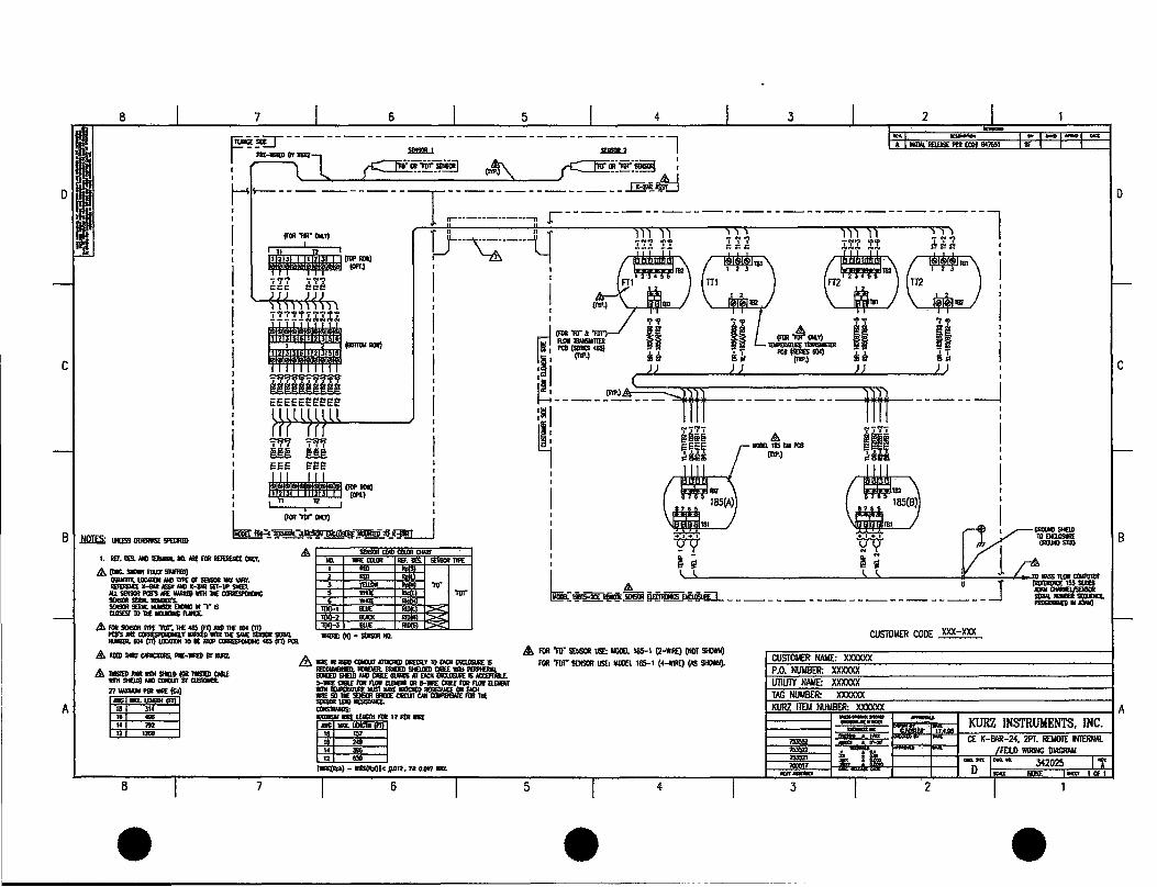
8
c
7 6 5 4 3 2
-----------l ------ Xllli!IB..Z I --------- .··;or~ I
~'i€r--- -~--- ··-·· .. I --------l I -...._._ ··-~-.,;;;) ________ ...J:!:P!ipf:::J ------------
: -----~ ------ _._,.., ,, &~:t~ I ------ ------ -~? I r-H----- - 1 ... ----·-··-··-n .r ..... I' ~ ~ ~ r:J.~. .. .~.. .... .. w~ I
: T i-··-.;·-.. -··-l[ G ~~~~·) ~ rn' ,' ~ m , • I
f-' '-.!> ' ' • (m . . ) • . I I fT1 .U, ·-1 I . I
7~"f"?"'~'f-7~?'?if
l!ftl!l!l!l!ll!l!l! eeeeeeeet:e
71'Fi ~ w w EEE ~~£! 1 ··~OPT~ I t lt l2 f I
I I I (IIJI"'IO"OIII.I')
~I~~__/ ji ii L~=-. ii ji I'QI($ERII!I<U) -~ -- I'QI($ERII!IIIOC) -- -~ i (nP.) u 3~ (nP~ u 3~
·~~ ~ JJ ~~ I) ~----.!"-'--4 -------- l _____ _j
~I 7 7'77 7 7'77 Sli!iiia & ;:EEE r~185!lii'QI lftt ~s@i (nP.) ;,sea
1111 ~ . 182
185(8)
I \l!flJI!fljll81 I
7
181
B I .NQIES; UIUSS OliOIISE- ~~~~~tO-~ I w w Vl I, IU. DIS. MID- Ill. Mt; feR lllltii!IU OIII.Y,
/A (DIG.- Fli.LT -) CIIIOIIiiiT,I.OI:AIICJIM!DlYJIE~---· lllltii!IU X-8111 ASST .1111) X-a.R SEt-uP SIIEI.
11.1. - PCB'S Nit: IINII@ WIIH 'II( CORIIUI'OIIIJN; ==:s--.. -··15 C1.0S£ST 10 'II( - IIMGE.
A~~~~-===LS!IIW.
&
_..IIOC(i1)I.OCA1XIIl0ii£ATCP~46S(fi)I'C8.
& FI£D - CANCIICRS. Pllt:..IIIR(l) 8T IIURZ. .& liiEIIIilllOCONOIIJAt!ACIEDOIIECII.TlOilCHENCI.OSUREIS
: ~ ~ ~ ~
~ ~ ~ I, I,
--- A______ u ·~W:.l!!!!!1!!!!!E!.~--------------------j
_&. FOR "FF• S£IISOR USE: IIOll£l. 185-1 (2-WIRE) (NOT SHOWN) FOR "FFr SENSOR USE: IIOll£l. 185-1 (4-WIRE) (AS SHOIN).
CUSTOMER CODE ~-XXX _
D
c
B
A
~~IIR::£sft.~~~ :a..-= Olllf feR:= r~-Olllf.:"3 aDIIlll =.:~lli!IOOECI!CIIIr.vt~FORII€ - KURZ IIlii NUIIBI:.R: xxxxxx A
=-""='·"::: KURZ INSTRUMENTS, INC . ......... t?PERM
l2T 1260
8 7 6 5 4
• • •

•
•
•
GLOSSARY
CORRECTION FACTOR: For multi-point insertion flow elements this is a number typically between 0.85 and 1.0 needed to convert a sparse matrix like a K-BAR to the true duct average. This number is velocity or flow rate dependent.
DEGC: Degrees Celsius.
DEGF: Degrees Fahrenheit.
KGH: Kilo Grams-per-Hour
KGM: Kilo Grams-per-Minute
UD: This is the Length to Diameter ratio in a pipe or duct between two locations. This non dimensional parameter is a comparative metric used to measure the distance between a flow disturbance and a measurement point. Both upstream, and downstream values are needed to quantify an installation .
MASS FLOW: Mass per unit time (i.e. Kg/s). This is the standard volumetric flow multiplied by the standard density.
METER: A virtual single task device which measures an engineering value and may totalize its rate.
PPH: Pounds-per-Hour
PPM: Pounds-per-Minute
PROFILE: See Velocity Profile.
PSIA: Pounds-per-Square Inch, Absolute pressure reference.
SBCF: Sensor Blockage Correction Factor. This is the geometric projection of the sensor element and probe support area subtracted from the duct area, this quantity normalized by the duct area.
SCFH: Standard Cubic Feet-per-Hour
Document# 360200, Revision A Page G1 ©1999 KURZ INSTRUMENTS

SCFM: Standard Cubic Feet-per-Minute
SCMH: Standard Cubic Meters-per-Hour
SCMM: Standard Cubic Meters-per-Minute
SCMS: Standard Cubic Meters-per-Second
SFPM: Standard Feet-per-Minute
SMPS: Standard Meters-per-Second
STANDARD VOLUMETRIC FLOW: is the pv product multiplied by an area (like a pipe cross section), normalized to a standard density.
Standard Volumetric Flow =Area x (Standard Velocity) =Apv/p5
where pis the actual density, vis the actual velocity and Psis the standard gas density and A is the area.
STANDARD VELOCITY: is the pv product normalized to a standard density.
Standard Velocity= pv/p5 with units of velocity
where pis the actual density, vis the actual velocity and Psis the standard gas density. For air this is 0.07387lb/ft3 at 25 °C and 29.92 in Hg.
VTM: Velocity/Temperature/Mapping. This is a calibration method where data at several temperatures are loaded into the flow meter. Flow signal linearization and then interpolation between the different temperature data sets are performed. This method is a second order correction to the sensors response and provides a more accurate temperature compensated flow measurement.
VELOCITY PROFILE: Due to drag and viscous fluid flow, the velocity in a duct tends to be its highest in the center and goes to zero at the duct walls. This shape is bullet nose at low velocities known as laminar, and flattens out at the higher more turbulent flow rates. A velocity dependent correction factor is measured based on an in-situ calibration to accurately convert the sensors velocity reading to the true average for computing flow or
Document# 360200, Revision A PageG2 ©1999 KURZ INSTRUMENTS
•
•
•

•
•
•
Appendix A
Thermal Anemometer Measurements
The Kurz thermal anemometers use two RIDs, one heated 50 to 100 oc above the ambient, the other monitors the ambient. The current required to keep the velocity element heated is the parameter calibrated in our wind tunnels.
Mass Rate
What does a thermal flow sensor measure? Because of the equations of forced convective heat transfer, the output of any thermal anemometer is proportional to the sensor's Reynolds number (Re ). Looking at the Reynolds number we can see how it measures mass rate per unit area, NOT volumetric flow rate. Therefore, the thermal anemometer automatically compensates for density.
Because a thermal anemometer measures the unit-area mass flow, it can be said to measure mass rate. In other words, it measures the true velocity, weighted by the density of the flowing gas. If the mass rate is normalized by a known density, it has velocity units, a term know as standard velocity. The next section helps explain where these ideas come from.
Mass Flow Equations
Reynolds Number
Lets look at the Reynolds number since it is proportional to the sensor's power or current when heated X degrees above the ambient:
where p = actual density v = actual velocity d = sensor's diameter 1-1 = gas viscosity _
Document# 360200, Revision A
vd Re = p
p.
PageA1 ©1999 KURZ INSTRUMENTS
It is the density and velocity (pv) product that makes the thermal anemometer a mass flowmeter. Density (p).hasunits of mass/volume and velocity (v) has units of length/time. So the pv product has units of (mass/time)/area or mass rate per unit area.
For example: p is kg/m3
, v is m/s
so pv is (kg/s)/m2
The sensor is sensitive to the energy that the gas molecules hitting it take away in the form of heat. This energy is proportional to the size and number of molecules that hit the sensor. It does not know about density and velocity. Small light gas molecules like hydrogen (H2) having a large surface area to mass ratio, are more efficient at transferring the vibrational heat energy of the sensor surface than large heavy molecules like Argon (Ar) having a small surface area to mass ratio.
Standard Velocity is the pv product normalized to a standard density.
Standard Velocity= pv/p5
where Psis the standard gas density. For air this is 0.07387lb/ft3 at 25 oc and 29.92 inHg.
Note: the density units cancel and you are left with velocity (m/s ). Typical units are: Standard-Feet-Per-Minute (SFPM) or Standard-Meters-Per-Second (SMPS). If the gas density doubled (you went from 15 PSIA to 30 PSIA) at the same actual velocity, the standard velocity would double. This also means that if the process gas is at the same temperature and pressure as the standard condition or the same density, the standard velocity and actual velocity are identical.
Document# 360200, Revision A PageA2 ©1999 KURZ INSTRUMENTS
•
•
•

•
•
•
Standard Volumetric Flow is the pv product multiplied by an area (like a pipe cross section), normalized to a standard density
Standard Volumetric Flow =Area x (Standard Velocity) =Apv/p8
where A is the area:
The units here are volume/time (m3/s) Typical Displayed units are:
SCFM, Standard Cubic Feet-per-Minute SCMM, Standard Cubic Meters-per-Minute SCFH, Standard Cubic Feet-per-Hour SCMH, Standard Cubic Meters-per-Hour
Mass Flow is obtained by simply multiplying the Standard Volumetric Flow by the Standard Density .
Mass Flow = (Standard Volumetric Flow) x Ps =Apv
The units here are mass/time (kg/s) Typical units are:
PPH, Pounds-per-Hour KGH, Kilograms-per-Hour
Different gases have different standard densities. This is often described as a reference density (air) multiplied by a specific gravity (sg).
Then: Mass Flow = (Standard Volumetric Flow) x Pairsg
= A(vp/ps) PairSg
Document# 360200, Revision A PageA3 ©1999 KURZ INSTRUMENTS

Conversion of Standard Velocity or Standard Volumetric Flow to actual requires only scaling the result for the gas density according to the ideal gas law.
or Va = Vs (P/PJ(f/fs)
Fa= Fs (P /P J(flfs)
where Va is actual velocity, V5 is standard velocity Fa is actual volumetric flow, F5 is standard volumetric flow Ps is the standard pressure in absolute units p a is the actual pressure in absolute units Ta is the actual temperature in absolute units (Kelvin or Rankin) T5 is the standard temperature in absolute units (Kelvin or Rankin) Note: °K = °C + 273.16, 0 R = °F + 459.67
Gas Property Induced Errors
There are secondary effects which cause mistracking of the idea thermal anemometer.
• Pressure changes will affect the calibration for some gasses. For example, N2
has a large 2.5% /100 psi shift in its viscosity which changes its mass flow reading the same amount. By contrast He has nearly no viscosity change with pressure.
• Temperature changes will affect the gas thermal conductivity and viscosity so the calibration will drift. This is typically 2.5% /100 °C. The minimum drift occurs near 3000 SFPM where the dynamic temperature compensation is performed.
• Temperature profiles in the pipe will produce flow errors. This is caused by using uninsulated pipe upstream of the sensor where the gas is above or below the ambient temperature.
• Low flow free convective heat transfer forces compete with forced convective and conductive heat transfer forces for power. This causes measurable errors ( depencling oa gas type, temperature, pressure, and orientation of sensor to both flow and gr.avity); starting at about 300 SFPM and becomes significant down at about 100 SFPM.
Document# 360200~ Revision A PageA4 ©·1999 KURZ INSTRUMENTS
_.~L
•
•
•

•
•
•
Flow Profiles And Correction Fa.ctors.
Velocity
i ~ '~---.I ~Vaverage
~---+ Pipe_ Cross i , Sect1on l ! . . .
Low Velocity (Reynolds Number) Laminar Profile
Velocity
~~Va~e !'--------+-~• Pipe Cross
Section
High Velocity (Reynolds Number) Turbulent Profile
Document# 360200, Revision A
At low velocity, a laminar velocity profile develops across the pipe cross section as shown in the figure. Note that the peak velocity is about 30% higher than the velocity average (V average).
At higher flow rates, a flatter velocity profile develops where the peak velocity is closer to the average. So depending on where the sensor is located, it will read a different fraction of the average velocity. It is the average velocity multiplied b-y-------------the cross sectional area that will obtain the total flow.
Page AS ©1999 KURZ INSTRUMENTS
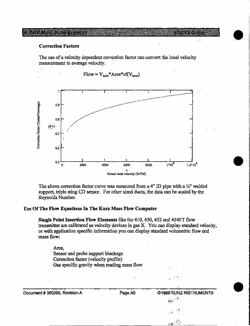
Correction Factors
The use of a velocjty dependent correction factor can convert the local velocity meaSurement to average velocity.
Flow = V1ocat * Area*cf(V local)
'i i
0.9
1 0.8 > / .._,
c'(v) ~ ·' /
&! 0.7
·~ ~ 8
0.5 0
v Sensor local velocity (SFPM)
The above correction factor curve was measured from a 4" lD pipe with a ~~~ welded support, triple sting CD sensor. For other sized ducts, the data can be scaled by the Reynolds Number.
Use Of The Flow Equations In The Kurz Mass Flow Computer
Single Point Insertion Flow Elements like the 410, 450, 452 and 454FT flow transmitter are calibrated as velocity devices in gas X. You can display standard velocity, or with .application specific information you can display standard volumetric flow and .mass flow.
Area, Sensor and probe support blockage Correction factor (velocity profile) Gas specific gravity when reading mass flow
DocumeAt # 360200, :Revision A PageA6
·- ~ ... ~
' ~. ~·~ i ... ~-·""f·-,··
•
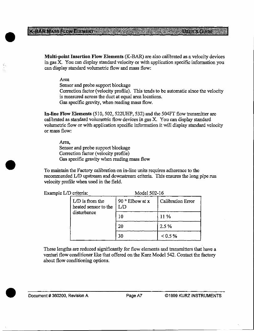
•
•
•
Multi-point Insertion Flow Elements (K-BAR) are also calibrated as a velocity devices in gas X. You can display standard velocity or with application specific information you can display standard volumetric flow and mass flow:
Area Sensor and probe support blockage Correction factor (velocity profile). This tends to be automatic since the velocity is measured across the duct at equal area locations. Gas specific gravity, when reading mass flow.
In-line Flow Elements (51 0, 502, 522UHP, 532) and the 504FT flow transmitter are calibrated as standard volumetric flow devices in gas X. You can display standard volumetric flow or with application specific information it will display standard velocity or mass flow:
Area, Sensor and probe support blockage Correction factor (velocity profile) Gas specific gravity when reading mass flow
To maintain the Factory calibration on in-line units requires adherence to the recommended LID upstream and downstream criteria. This ensures the long pipe run velocity profile when used in the field.
Example LID criteria: Model 502-16
LID is from the 90 o Elbow at x Calibration Error heated sensor to the LID disturbance
10 11%
20 2.5%
30 <0.5%
These lengths are reduced significantly for flow elements and transmitters that have a venturi flow conditioner like that offered on the Kurz Model 542. Contact the factory about flow conditioning options .
Document# 360200, Revision A PageA7 ©1999 KURZ INSTRUMENTS

Problems:
Air flow of 100,000 lblhr through a 3' x 3' square duct, 90°F, 20 PSIG
a. What is mass flow in SCFM -------------------------b. What is velocity in SFPM ---------------
c. The actual velocity is -----------------------d. What range does Kurz calibrate to ------------------
Nitrogen flow of 10 ACFM through a 3 II Schedule 40 pipe, 11 0°F' 50 PSIG
e. What is the area -----------------------------f. What is the flow rate in SCFM -------------------------g. The velocity in SFPM is ---------------------
h. The calibration max. range is ----------------------
Answers on the Next Page:
Document# 360200, Revision A Page AS ©1999 KURZ INSTRUMENTS
•
•
•
•
•
•
Worked out answers to the previous questions.
Kurz Standard Reference Conditions. Air density: 0.0739lb/ft3 at 77 °F and 14.69 psia,
a: 100,000 lblhr x (1 hr/60 min) x 1 ft3/0.0739lb = 22,553 ft3/min which is 22,553 SCFM since our density was at standard conditions.
b: Velocity= (Volume rate) /Area= 22,553/ (3 x 3) . = 2506 SFPM.
c: Va = V8 (P/PJ(T/f8) = 2506 (14.69/{20 + 14.69}){460 + 90)/(460 +77) = 1087FPM.
d: Calibrated rates are about 1.5 times the expected maximum. So 2506 SFPM x 1.5 ,.., 4000 SFPM .
e: ID of schedule 40 3" pipe is ,.., 3" Area= 3.14 02/4 = 3.14(3112)2 /4 = 0.0491 ft2.
f: Same as C above but the other way around with flow. Fs = Fa(Pa IP8)(T8 ITa)= 10 (50+ 14.69)/14.69 {460 +77)/(460 +110)
= 41.49 SCFM.
g: Volumetric Rate I Area= Velocity= 41.49 SCFM I 0.0491 ft2
=845 SFPM.
h: Calibrated rates are about 1.5 times the expected maximum. So 41.49 SCFM x 1.5 - 60 SCFM .
Document# 360200, Revision A PageA9 ©1'999 KURZ INSTRUMENTS
KURZ INSTRUMENTS™ K-BAR™
Multi-Point Insertion Mass Flow Element
User's Guide DOC # 360200, Rev. A
KURZ INSTRUMENTS, INC. 2411 GARDEN ROAD MONTEREY, CA 93940-5394 USA
Tel: (831)646-5911 Fax: (831)646-8901 www.kurz-instruments~com