Embed Size (px)
Citation preview

05.01
Page
HanCom
Contents
Han-Com®
Summary . . . . . . . . . . . . . . . . . . . . . . . . . . . . . . . . . . . . . . . . . . . . . . . . . . . 05.02
Han® K 8/24 . . . . . . . . . . . . . . . . . . . . . . . . . . . . . . . . . . . . . . . . . . . . . . . . . 05.10
Han® K 4/0, 4/2 . . . . . . . . . . . . . . . . . . . . . . . . . . . . . . . . . . . . . . . . . . . . . . 05.14
Han® K 6/12 . . . . . . . . . . . . . . . . . . . . . . . . . . . . . . . . . . . . . . . . . . . . . . . . . 05.16
Han® K 6/36 . . . . . . . . . . . . . . . . . . . . . . . . . . . . . . . . . . . . . . . . . . . . . . . . . 05.18
Han® K 12/2 (12 HsC) . . . . . . . . . . . . . . . . . . . . . . . . . . . . . . . . . . . . . . . . . 05.20
Han® K 4/8 . . . . . . . . . . . . . . . . . . . . . . . . . . . . . . . . . . . . . . . . . . . . . . . . . . 05.26
Han® K 6/6 . . . . . . . . . . . . . . . . . . . . . . . . . . . . . . . . . . . . . . . . . . . . . . . . . . 05.28
Han® K 8/0 . . . . . . . . . . . . . . . . . . . . . . . . . . . . . . . . . . . . . . . . . . . . . . . . . . 05.30
Assembly details for Han® K 6/6 and K 8/0 . . . . . . . . . . . . . . . . . . . . . . . . . 05.35

05.02
B
10
16
24
3248
HanCom
Han-Com® Summary
Size Description
Han® K 8/24Power area 16 A / 230/400 VSignal area 10 A / 160 V
Crimp terminalPage 05.10
Han® K 4/0, 4/2 Han® K 6/12 Han® K 6/36 Han® K 12/2Power area 80 A / 830 V 40 A / 690 V 40 A / 690 V 40 A / 690 VSignal area 16 A / 400 V 10 A / 230/400 V 10 A / 160 V 10 A / 250 V
Screw terminal Screw terminal Crimp terminal Crimp terminalPage 05.14 Page 05.16 Page 05.18 Page 05.20
Han® K 4/8 Han® K 6/6 Han® K 8/0Power area 80 A / 400 V 100 A / 690 V 100 A / 690 VSignal area 16 A / 400 V 16 A / 400 V
Screw terminal Screw terminal Screw terminalPage 05.26 Page 05.30 Page 05.31
suitable for 2 inserts of size 16 B
suitable for 2 inserts of size 24 B

05.03
HanCom
Han-Com®
Han® K 6/12
Summary
Type identification
Identification of contact position
Han® K 4/00 4+PE 80 830 screw – – – – 16 B, 32 B
4/20 4+PE 80 830 screw 2 16 400 screw 16 B, 32 B
4/80 4+PE 80 400 screw 8 16 400 screw 24 B, 48 B
6/60 6+PE 100 690 screw 6 16 400 screw 24 B, 48 B
8/00 8+PE 100 690 screw 8 – – – 24 B, 48 B
6/12 6+PE 40 690 screw 12 10 230/400 screw 16 B, 32 B
6/36 6+PE 40 690 crimp 36 10 160 crimp 16 B, 32 B
8/24 8+PE 16 230/400 crimp 24 10 160 crimp 10 B
12/20 12+PE 40 690 crimp 2 10 250 crimp 16 B, 32 B
Number NumberA V~ Termination A V~ Termination Sizeof pins of pins
Technical characteristics SuitableType Han® Hoods/
Power area Signal area Housings
Number of signal contacts
Number of power contacts
Series Han® K / Han-Com®
Industrial connectors Han®
Comment for users
For the combination of several circuits in one cable and/or e.g. one connector the following standards are valid
VDE 0100/1.97 § 411.1.3.2 and DIN EN 60 204/11.98 § 14.1.3
– Han® K connectors in the power area from 1 to ...in the signal area from 11 to …
– Han® K 4/8 and Han® K 8/24 consecutively from 1 to …
– Han® K 12/2 in the power area from 1 to 12in the signal area with “a” and “b”
05.10
HanCom
Han® K 8/24 Technical characteristics
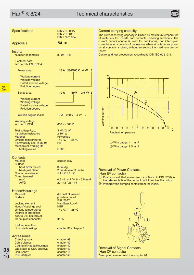
Current carrying capacityThe current carrying capacity is limited by maximum temperatureof materials for inserts and contacts including terminals. Thecurrent capacity-curve is valid for continuous, not interruptedcurrent-loaded contacts of connectors when simultaneous poweron all contacts is given, without exceeding the maximum tempe-rature.
Control and test procedures according to DIN IEC 60 512-3.
Removal of Power Contacts(Han E® contacts)➀ Push cross-slotted screwdriver (size 0 acc. to DIN 5260) in
the relevant hole of the contact until it reaches the bottom.➁ Withdraw the crimped contact from the insert.
Removal of Signal Contacts(Han D® contacts)Description see removal tool chapter 99
Wor
king
cur
rent
Ambient temperature
➀ Wire gauge: 4,0 mm2
➁ Wire gauge: 2.5 mm2
Specifications DIN VDE 0627DIN VDE 0110DIN EN 61 984
Approvals ,
InsertsNumber of contacts 8 / 24 + PE
Electrical data acc. to DIN EN 61 984
Power area 16 A 230/400 V 4 kV 3
Working currentWorking voltageRated impulse voltagePollution degree
Signal area 10 A 160 V 2.5 kV 3
Working currentWorking voltageRated impulse voltagePollution degree
- Pollution degree 2 also 10 A 250 V 4 kV 2
Working voltageacc. to UL/CSA 600 V / 300 V
Test voltage Urms 3 kV / 2 kVInsulation resistance ≥ 1010 ΩMaterial PolyamideLimiting temperatures - 40 OC / +125 OCFlammability acc. to UL 94 HBMechanical working life
- Mating cycles ≥ 500
ContactsMaterial copper alloySurface
- hard-silver plated 3 µm Ag- hard-gold plated 2 µm Au over 3 µm Ni
Contact resistance ≤ 1 mΩ / 3 mΩCrimp terminal
- mm2 0.5 - 4 mm² / 0.14 - 2.5 mm²- AWG 20 - 12 / 25 - 14
Hoods/HousingsMaterial die cast aluminiumSurface powder-coated
RAL 7037Locking element Han-Easy Lock®
Hoods/Housings seal NBRLimiting temperatures - 40 OC / +125 OCDegree of protection acc. to DIN EN 60 529 for coupled connector IP 65
Further selection of hoods/housings chapter 30 / chapter 31
AccessoriesCrimping tools chapter 99Cable clamps chapter 40Coding of Hoods/Housings chapter 40Label acc. to CSA-approval chapter 40Han-Snap® chapter 11PCB-adapter chapter 40

05.11
HanCom
Han® K 8/24 400/160 V16/10 A
Crimp terminal Han® KOrder crimp contactsseparately
8/24 09 38 032 3001 09 38 032 3101
0.5 09 33 000 6121 09 33 000 62200.75 09 33 000 6114 09 33 000 62141.0 09 33 000 6105 09 33 000 62051.5 09 33 000 6104 09 33 000 62042.5 09 33 000 6102 09 33 000 62024.0 09 33 000 6107 09 33 000 62070.5 09 33 000 6122 09 33 000 62220.75 09 33 000 6115 09 33 000 62151.0 09 33 000 6118 09 33 000 62181.5 09 33 000 6116 09 33 000 62162.5 09 33 000 6123 09 33 000 62234.0 09 33 000 6119 09 33 000 62210.75-1 09 33 000 61091.5 09 33 000 61102.5 09 33 000 6111
0.14-0.37 09 15 000 6104 09 15 000 62040.5 09 15 000 6103 09 15 000 62030.75 09 15 000 6105 09 15 000 62051.0 09 15 000 6102 09 15 000 62021.5 09 15 000 6101 09 15 000 62012.5 09 15 000 6106 09 15 000 62060.14-0.37 09 15 000 6124 09 15 000 62240.5 09 15 000 6123 09 15 000 62230.75 09 15 000 6125 09 15 000 62251.0 09 15 000 6122 09 15 000 62221.5 09 15 000 6121 09 15 000 62212.5 09 15 000 6126 09 15 000 6226
Part No.
Identification Series Male insert (M) Female insert (F) Drawing Dimensions in mm
Wire gauge Part No.
Identification (mm2) Male contacts Female contacts Drawing Dimension in mm
Inserts
Number of contacts
8/24
1) Distance for contact max. 21 mm
Contact arrangementView from terminationside
FOC contactsfor 1 mm 20 10 001 3211 20 10 001 3221plastic fibre
Crimp contactsPower contacts
silver plated
gold plated
Relay contactsilver plated
Signal contact
silver plated
gold plated
Operating contact
Identification
* on the back crimp collar
Relay contact
0.14-0.37 mm2 AWG 26-22 0.90 mm 8 mm0.5 mm2 AWG 20 1.10 mm 8 mm0.75 mm2 AWG 18 1.30 mm 8 mm1.0 mm2 AWG 18 1.45 mm 8 mm1.5 mm2 AWG 16 1.75 mm 8 mm2.5 mm2 AWG 14 2.25 mm 6 mm
StrippingWire gauge ø length
Stock items in bold type
no groove 0.5 mm2 AWG 20 7.5 mm1 groove* 0.75 mm2 AWG 18 7.5 mm1 groove 1.0 mm2 AWG 18 7.5 mm2 grooves 1.5 mm2 AWG 16 7.5 mm3 grooves 2.5 mm2 AWG 14 7.5 mmno groove 4.0 mm2 AWG 12 7.5 mm
StrippingIdentification Wire gauge length
Size 10 B

05.12
HanCom
Standard Hoods/Housings with 2 levers on the housing Size 10 B
Part No.
Identification Low construction High construction M Drawing Dimensions in mm
Hoodsside-entry
19 30 010 1520 20
19 30 010 1521 25
19 30 010 0527 32
Hoodstop-entry
19 30 010 1420 20
19 30 010 1421 25
19 30 010 0427 32
Protection covers for hoodsthermoplastic/metal 09 30 010 5401
09 30 010 5423
Housingssurface mounting
1 side-entry 19 30 010 1230 2019 30 010 1231 19 30 010 0231 25
2 side-entries 19 30 010 1270 2019 30 010 0271 2519 30 010 0272 32
Protection coversfor housings bulkhead/surface mountingthermoplastic/metal 09 30 010 5407
09 30 010 5425
Hoods cable to cable
19 30 010 1730 2019 30 010 0736 2519 30 010 0737 32
Protection coverfor hoods cable to cablemetal 09 30 010 5427
Hou
sing
sH
oods
Panel cut out 60 x 35 mm
Blind way for one cable entry
a b hLow construction 40 52 54High construction 45 57 81
Stock items in bold type
Housingbulkheadmounting 09 30 010 0301 –
hLow construction 47.5High construction 74.5

05.13
HanCom
09 30 010 5406
Standard Hoods/Housings with 1 lever on the housing Size 10 B
Part No.
Identification Low construction High construction M Drawing Dimensions in mm
Hoodsside-entry
19 30 010 1540 20
19 30 010 1541 25
19 30 010 0547 32
Hoodstop-entry
19 30 010 1440 20
19 30 010 1441 25
19 30 010 0447 32
Housingsbulkhead mounting
09 30 010 0305 –
with thermo-plastic cover
09 30 010 0303 –with metal
cover09 30 010 0318 –
Housings 1 side-entry 19 30 010 1250 20surface mounting
2 side-entries 19 30 010 1290 2019 30 010 0291 2519 30 010 0292 32
with thermo-plastic cover
1 side-entry 19 30 010 1255 20
with thermo- with thermo-plastic cover plastic cover
2 side-entries 19 30 010 1295 2019 30 010 0296 2519 30 010 0297 32
with metal with metalcover cover
19 30 010 2295 2019 30 010 7296 25
Hoods cable to cable
19 30 010 1750 2019 30 010 0756 2519 30 010 0757 32
Hou
sing
sH
oods
Panel cut out 60 x 35 mm
1) Blind way for one cable entry
Stock items in bold type
hLow construction 47.5High construction 74.5
a b hLow construction 40 52 54High construction 45 57 81
Dust protectioncover

05.14
HanCom
Han® K 4/0, 4/2 Technical characteristics
Current carrying capacityThe current carrying capacity is limited by maximum temperatureof materials for inserts and contacts including terminals. Thecurrent capacity-curve is valid for continuous, not interruptedcurrent-loaded contacts of connectors when simultaneous poweron all contacts is given, without exceeding the maximum tempe-rature.
Control and test procedures according to DIN IEC 60 512-3.
Wor
king
cur
rent
Ambient temperature
➀ Wire gauge: 16 mm2
➁ Wire gauge: 10 mm2
Specifications DIN VDE 0627DIN VDE 0110DIN EN 61 984
Approvals ,
InsertsNumber of contacts 4 / 2 + PE
Electrical dataacc. to DIN EN 61 984
Power area 80 A 830 V 8 kV 3
Working currentWorking voltageRated impulse voltagePollution degree
– Pollution degree 2 also 80 A 1000 V 8 kV 2
Signal area 16 A 400 V 6 kV 3
Working currentWorking voltageRated impulse voltagePollution degree
– Pollution degree 2 also 16 A 400/690 V 6 kV 2
Working voltageacc. to UL/CSA 600 V / 300 V
Insulation resistance ≥ 1010 ΩMaterial PolycarbonateLimiting temperatures - 40 OC / +125 OCFlammability acc. to UL 94 V 0Mechanical working life
- Mating cycles ≥ 500
Contacts
Power contactsMaterial copper alloySurface
- hard-silver plated 3 µm AgContact resistance ≤ 0.3 mΩScrew terminal
- Wire gauge1) 1.5 - 16 mm²- AWG 16 - 6
- Tightening torque mm² 1.5 2.5 4 6 10 16
Nm 1.2 2 3 3 3 3
Signal contactsMaterial copper alloySurface
- hard-silver plated 3 µm AgContact resistance ≤ 1 mΩScrew terminal
- Wire gauge1) 0.5 - 2.5 mm²- AWG 20 - 14- Tightening torque 0.5 Nm
In accordance with the appropriate regulations a wire-end sleevehas to be used at clamps without wire protection (s. p. 00.12).
Hoods/HousingsMaterial die cast aluminiumSurface powder-coated
RAL 7037Locking element Han-Easy Lock®
Hoods/Housings seal NBRLimiting temperatures - 40 OC / +125 OCDegree of protection acc. to DIN EN 60 529for coupled connector IP 65
Further selectionof hoods/housings chapter 30 / chapter 31
AccessoriesCable clamps chapter 40Coding of hoods/housings chapter 40Label acc. to CSA-approval chapter 40Han-Snap® chapter 11
1) geometrical diameter

05.15
Han® K 4/0, Han® K 4/2 830/400 V80/16 A
HanCom
Screw terminal Han® K
4/0 09 38 006 2611 09 38 006 2711
4/2 09 38 006 2601 09 38 006 2701
Part No.
Identification Series Male insert (M) Female insert (F) Drawing Dimensions in mm
Inserts
Number of contacts
4/0, 4/2
1) Distance for contact max. 21 mm
Contact arrangement View from termination side
Han® K 4/0 Han® K 4/2
option
Hoods/Housings from page 05.22 onwards Stock items in bold type
Size 16 B
05.16
HanCom
Han® K 6/12 Technical characteristics
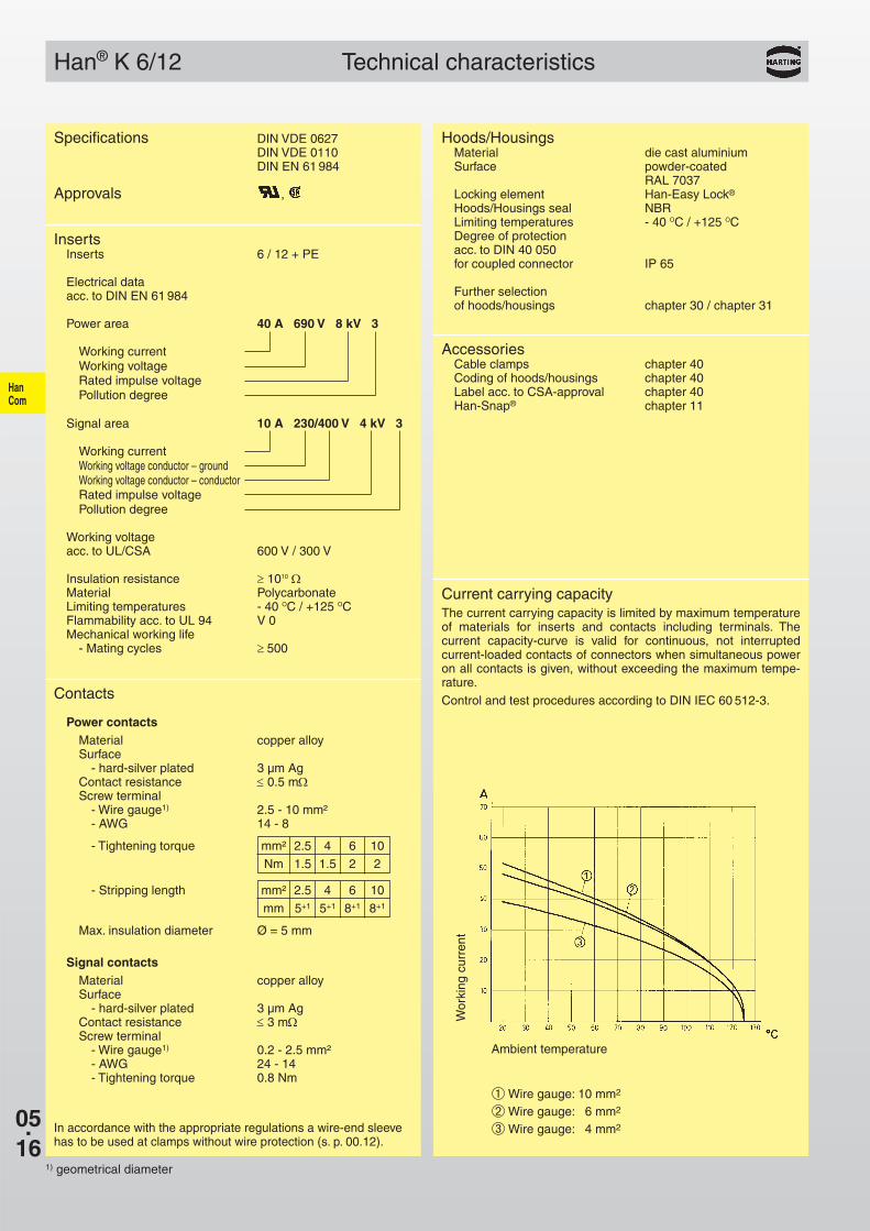
Current carrying capacityThe current carrying capacity is limited by maximum temperatureof materials for inserts and contacts including terminals. Thecurrent capacity-curve is valid for continuous, not interruptedcurrent-loaded contacts of connectors when simultaneous poweron all contacts is given, without exceeding the maximum tempe-rature.
Control and test procedures according to DIN IEC 60 512-3.
Wor
king
cur
rent
Ambient temperature
➀ Wire gauge: 10 mm2
➁ Wire gauge: 6 mm2
➂ Wire gauge: 4 mm2
Specifications DIN VDE 0627DIN VDE 0110DIN EN 61 984
Approvals ,
InsertsInserts 6 / 12 + PE
Electrical dataacc. to DIN EN 61 984
Power area 40 A 690 V 8 kV 3
Working currentWorking voltageRated impulse voltagePollution degree
Signal area 10 A 230/400 V 4 kV 3
Working currentWorking voltage conductor – groundWorking voltage conductor – conductorRated impulse voltagePollution degree
Working voltageacc. to UL/CSA 600 V / 300 V
Insulation resistance ≥ 1010 ΩMaterial PolycarbonateLimiting temperatures - 40 OC / +125 OCFlammability acc. to UL 94 V 0Mechanical working life
- Mating cycles ≥ 500
Contacts
Power contactsMaterial copper alloySurface
- hard-silver plated 3 µm AgContact resistance ≤ 0.5 mΩScrew terminal
- Wire gauge1) 2.5 - 10 mm²- AWG 14 - 8
- Tightening torque mm² 2.5 4 6 10
Nm 1.5 1.5 2 2
- Stripping length mm² 2.5 4 6 10
mm 5+1 5+1 8+1 8+1
Max. insulation diameter Ø = 5 mm
Signal contactsMaterial copper alloySurface
- hard-silver plated 3 µm AgContact resistance ≤ 3 mΩScrew terminal
- Wire gauge1) 0.2 - 2.5 mm²- AWG 24 - 14- Tightening torque 0.8 Nm
In accordance with the appropriate regulations a wire-end sleevehas to be used at clamps without wire protection (s. p. 00.12).
Hoods/HousingsMaterial die cast aluminiumSurface powder-coated
RAL 7037Locking element Han-Easy Lock®
Hoods/Housings seal NBRLimiting temperatures - 40 OC / +125 OCDegree of protection acc. to DIN 40 050 for coupled connector IP 65
Further selectionof hoods/housings chapter 30 / chapter 31
AccessoriesCable clamps chapter 40Coding of hoods/housings chapter 40Label acc. to CSA-approval chapter 40Han-Snap® chapter 11
1) geometrical diameter

05.17
M 3 x 10
HanCom
Screw terminal Han® K
6/12 09 38 018 2601 09 38 018 2701
Screwdriverfor axial setscrew
09 99 000 0313
Working instructionsfor axial setscrew
Han® K 6/12
Part No.
Identification Series Male insert (M) Female insert (F) Drawing Dimensions in mm
Inserts
Number of contacts
6/12
For stranded wire 2.5 ... 10 mm2 fine wire(superfine wire 2.5 ... 6 mm2)Don’t twist stranded wire further!
Example: Male insert
Insert stranded wire in contact chamber.
During tightening of the lock nut, hold stranded wire in position.
Tightening torque: 1 Nm max.
1) Distance for contact max. 21 mm
Contact arrangement View from termination side
Hoods/Housings from page 05.22 onwards Stock items in bold type
690/400 V40/10 ASize 16 B

05.18
HanCom
Wor
king
cur
rent
Ambient temperature
➀ Wire gauge: 6 mm2
➁ Wire gauge: 4 mm2
Han® K 6/36 Technical characteristics
Current carrying capacityThe current carrying capacity is limited by maximum temperatureof materials for inserts and contacts including terminals. Thecurrent capacity-curve is valid for continuous, not interruptedcurrent-loaded contacts of connectors when simultaneous poweron all contacts is given, without exceeding the maximum tempe-rature.
Control and test procedures according to DIN IEC 60 512-3.
Removal of Power Contacts(Han® C contacts)Description see removal tool chapter 99
Specifications DIN VDE 0627DIN VDE 0110DIN EN 61 984
Approvals ,
InsertsNumber of contacts 6 / 36 + PE
Electrical data acc. to DIN EN 61 984
Power area 40 A 690 V 8 kV 3
Working currentWorking voltageRated impulse voltagePollution degree
Signal area 10 A 160 V 2,5 kV 3
Working currentWorking voltageRated impulse voltagePollution degree
- Pollution degree 2 also 10 A 250 V 4 kV 2
Working voltageacc. to UL/CSA 600 V / 300 V
Test voltage Urms 3 kV / 2 kVInsulation resistance ≥ 1010 ΩMaterial PolycarbonateLimiting temperatures - 40 OC / +125 OCFlammability acc. to UL 94 V 0Mechanical working life
- Mating cycles ≥ 500
ContactsMaterial copper alloySurface
- hard-silver plated 3 µm Ag- hard-gold plated 2 µm Au over 3 µm Ni
Contact resistance ≤ 0.3 mΩ / 3 mΩCrimp terminal
- mm2 1.5 - 6 mm² / 0.14 - 2.5 mm²- AWG 16 - 10 / 26 - 14
Max. insulation- Power contacts ø = 5 mm
Hoods/HousingsMaterial die cast aluminiumSurface powder-coated
RAL 7037Locking element Han-Easy Lock®
Hoods/Housings seal NBRLimiting temperatures - 40 OC / +125 OCDegree of protection acc. to DIN EN 60 529 for coupled connector IP 65
Further selectionof hoods/housings chapter 30 / chapter 31
AccessoriesCrimping tools chapter 99Cable clamps chapter 40Coding of Hoods/Housings chapter 40Label acc. to CSA-approval chapter 40Han-Snap® chapter 11PCB-Adapter chapter 40

05.19
HanCom
Han® K 6/36 690/160 V40/10 A
Crimp terminal Han® KOrder crimp contactsseparately
6/36 09 38 042 3001 09 38 042 3101
1.5 09 32 000 6104 09 32 000 62042.5 09 32 000 6105 09 32 000 62054.0 09 32 000 6107 09 32 000 62076.0 09 32 000 6108 09 32 000 6208
0.14-0.37 09 15 000 6104 09 15 000 62040.5 09 15 000 6103 09 15 000 62030.75 09 15 000 6105 09 15 000 62051.0 09 15 000 6102 09 15 000 62021.5 09 15 000 6101 09 15 000 62012.5 09 15 000 6106 09 15 000 6206
0.14-0.37 09 15 000 6124 09 15 000 62240.5 09 15 000 6123 09 15 000 62230.75 09 15 000 6125 09 15 000 62251.0 09 15 000 6122 09 15 000 62221.5 09 15 000 6121 09 15 000 62212.5 09 15 000 6126 09 15 000 6226
Part No.
Identification Series Male insert (M) Female insert (F) Drawing Dimensions in mm
Wire gauge Part No.
Identification (mm2) Male contacts Female contacts Drawing Dimensions in mm
Inserts
Number of contacts
6/36
FOC contactsfor 1 mm 20 10 001 3211 20 10 001 3221plastic fibre
Crimp contactsPower contacts
silverplated
Signal contacts
silverplated
goldplated
0.14-0.37 mm2 AWG 26-22 0.90 mm 8 mm0.5 mm2 AWG 20 1.10 mm 8 mm0.75 mm2 AWG 18 1.30 mm 8 mm1.0 mm2 AWG 18 1.45 mm 8 mm1.5 mm2 AWG 16 1.75 mm 8 mm2.5 mm2 AWG 14 2.25 mm 6 mm
StrippingWire gauge ø length
1) Distance for contact max. 21 mm
Contact arrangement View from termination side
Hoods/Housings from page 05.22 onwards Stock items in bold type
StrippingWire gauge ø length
1.5 mm2 AWG 16 1.75 mm 9.0 mm2.5 mm2 AWG 14 2.25 mm 9.0 mm4.0 mm2 AWG 12 2.85 mm 9.5 mm6.0 mm2 AWG 10 3.50 mm 9.5 mm
Size 16 B

05.20
HanCom
Han® K 12/2 (12 HsC) Technical characteristics
Wor
king
cur
rent
Ambient temperature
➀ Wire gauge: 6 mm2
➁ Wire gauge: 4 mm2
Current carrying capacityThe current carrying capacity is limited by maximum temperatureof materials for inserts and contacts including terminals. Thecurrent capacity-curve is valid for continuous, not interruptedcurrent-loaded contacts of connectors when simultaneous poweron all contacts is given, without exceeding the maximum tempe-rature.
Control and test procedures according to DIN IEC 60 512-3.
Removal of Power Contacts(Han® C contacts)Description see removal tool chapter 99
Specifications DIN VDE 0627DIN VDE 0110DIN EN 61 984
Approvals ,
InsertsNumber of contacts 12 / 2 + PE
Electrical dataacc. to DIN EN 61 984
Power area 40 A 690 V 8 kV 3
Working currentWorking voltageRated impulse voltagePollution degree
Signal area 10 A 250 V 4 kV 3
Working currentWorking voltageRated impulse voltagePollution degree
Working voltageacc. to UL/CSA 600 V / 300 V
Insulation resistance ≥ 1010 ΩMaterial PolycarbonateLimiting temperatures - 40 OC / +125 OCFlammability acc. to UL 94 V 0Mechanical working life
- Mating cycles ≥ 500
ContactsMaterial copper alloySurface
- hard-silver plated 3 µm Ag- hard-gold plated 2 µm Au over 3 µm Ni
Contact resistance ≤ 0.3 mΩ / 3 mΩCrimp terminal
- mm2 1.5 - 6 mm² / 0.14 - 2.5 mm²- AWG 16 - 10 / 26 - 14
Hoods/HousingsMaterial die cast aluminiumSurface powder-coated
RAL 7037Locking element Han-Easy Lock®
Hoods/Housings seal NBRLimiting temperatures - 40 OC / +125 OCDegree of protection acc. to DIN EN 60 529 for coupled connector IP 65
Further selectionof hoods/housings chapter 30 / chapter 31
AccessoriesCrimping tools chapter 99Cable clamps chapter 40Coding of hoods/housings chapter 40Label acc. to CSA-approval chapter 40Han-Snap® chapter 11

05.21
HanCom
Han® K 12/2 (12 HsC) 690/250 V40/10 A
Crimp terminal Han® KOrder crimp contactsseparately
12/2 09 32 012 3001 09 32 012 3101
1.5 09 32 000 6104 09 32 000 62042.5 09 32 000 6105 09 32 000 62054.0 09 32 000 6107 09 32 000 62076.0 09 32 000 6108 09 32 000 6208
0.14-0.37 09 15 000 6104 09 15 000 62040.5 09 15 000 6103 09 15 000 62030.75 09 15 000 6105 09 15 000 62051.0 09 15 000 6102 09 15 000 62021.5 09 15 000 6101 09 15 000 62012.5 09 15 000 6106 09 15 000 6206
0.14-0.37 09 15 000 6124 09 15 000 62240.5 09 15 000 6123 09 15 000 62230.75 09 15 000 6125 09 15 000 62251.0 09 15 000 6122 09 15 000 62221.5 09 15 000 6121 09 15 000 62212.5 09 15 000 6126 09 15 000 6226
Han® K 12/2 (12 HsC)
Part No.
Identification Series Male insert (M) Female insert (F) Drawing Dimensions in mm
Wire gauge Part No.
Identification (mm2) Male contacts Female contacts Drawing Dimensions in mm
Inserts
Number of contacts
12/2
FOC contactsfor 1 mm 20 10 001 3211 20 10 001 3221plastic fibre
Crimp contactsPower contacts
silverplated
Signal contacts
silverplated
goldplated
0.14-0.37 mm2 AWG 26-22 0.90 mm 8 mm0.5 mm2 AWG 20 1.10 mm 8 mm0.75 mm2 AWG 18 1.30 mm 8 mm1.0 mm2 AWG 18 1.45 mm 8 mm1.5 mm2 AWG 16 1.75 mm 8 mm2.5 mm2 AWG 14 2.25 mm 6 mm
StrippingWire gauge ø length
1) Distance for contact max. 21 mm
Contact arrangement View from termination side
Stock items in bold type
StrippingWire gauge ø length
1.5 mm2 AWG 16 1.75 mm 9.0 mm2.5 mm2 AWG 14 2.25 mm 9.0 mm4.0 mm2 AWG 12 2.85 mm 9.5 mm6.0 mm2 AWG 10 3.50 mm 9.5 mm
Size 16 B

05.22
HanCom
Standard Hoods/Housings with 2 levers on the housing Size 16 B
Part No.
Identification Low construction High construction M Drawing Dimensions in mm
Hoodsside-entry
19 30 016 1521 2519 30 016 1522 32
19 30 016 0527 3219 30 016 0528 40
Hoodstop-entry
19 30 016 1421 2519 30 016 1422 32
19 30 016 0427 3219 30 016 0428 40
Protection covers for housingsthermoplastic/metal
09 30 016 5401
09 30 016 5422
Housingssurface mounting 1 side-entry 19 30 016 1231 25
19 30 016 0232 32
2 side-entries 19 30 016 1271 19 30 016 0271 2519 30 016 0272 3219 30 016 0273 40
Protection coversfor housings bulkhead mountingthermoplastic/metal 09 30 016 5405
09 30 016 5425
Hoodscable to cable
19 30 016 1731 19 30 016 0736 2519 30 016 0737 32
Protection coverfor hoods cable to cablemetal
09 30 016 5426
Hou
sing
sH
oods
Panel cut out 82 x 35 mm
Blind way for one cable entry
hLow construction 56High construction 81
hLow construction 47.5High construction 78.5
Housingbulkheadmounting 09 30 016 0301 –
Stock items in bold type

05.23
HanCom
09 30 016 5406
Standard Hoods/Housings with 1 lever on the housing Size 16 B
Part No.
Identification Low construction High construction M Drawing Dimensions in mm
Hoodsside-entry
19 30 016 1541 2519 30 016 1542 32
19 30 016 0547 3219 30 016 0548 40
Hoodstop-entry
19 30 016 1441 2519 30 016 1442 32
19 30 016 0447 3219 30 016 0448 40
Housingsbulkhead mounting
09 30 016 0307 –
with thermo-plastic cover
09 30 016 0306 –
with metalcover
09 30 016 0318 –
Housingssurface mounting 1 side-entry 19 30 016 1251 25
19 30 016 0252 32
2 side-entries 19 30 016 1291 19 30 016 0291 2519 30 016 0292 32
with thermo-plastic cover
1 side-entry 19 30 016 1256 25
with thermo- with thermo-plastic cover plastic cover
2 side-entries 19 30 016 1296 2519 30 016 0297 32
with metal cover with metal cover2 side-entries 19 30 016 2296 25
19 30 016 7297 32
Hoodscable to cable
19 30 016 1751 2519 30 016 0757 32
Hou
sing
sH
oods
Panel cut out 82 x 35 mm
1) Blind way for one cable entry
Stock items in bold type
hLow construction 47.5High construction 78.5
hLow construction 56High construction 81
Dust protectioncover

05.24
HanCom
Stock items in bold type
Standard Hoods/Housings with 2 levers on the housing Size 32 B
Identification Part No. M Drawing Dimensions in mm
Hoodsside-entry
19 30 032 0527 3219 30 032 0528 4019 30 032 0529 50
Housingbulkhead mounting
09 30 032 0301 –
Hou
sing
sH
oods
Hoodstop-entry
19 30 032 0427 3219 30 032 0428 4019 30 032 0429 50
Housingssurface mounting
19 30 032 0232 1 x 32
19 30 032 0272 2 x 32
19 30 032 0273 2 x 40
Protection covers
for housings09 30 032 5425 –
Panel cut out
Protection coverfor hoods
09 30 032 5420 –
Hoodscable to cable
19 30 032 0738 2 x 40
Blind way for one cable entry

05.25
HanCom
Application
Automatic milking chambersPROLION, Holding N.V., Netherlands

05.26
HanCom
Han® K 4/8 Technical characteristics
Current carrying capacityThe current carrying capacity is limited by maximum temperatureof materials for inserts and contacts including terminals. Thecurrent capacity-curve is valid for continuous, not interruptedcurrent-loaded contacts of connectors when simultaneous poweron all contacts is given, without exceeding the maximum tempe-rature.
Control and test procedures according to DIN IEC 60 512-3.
Wor
king
cur
rent
Ambient temperature
➀ Wire gauge: 16 mm2
➁ Wire gauge: 10 mm2
Specifications DIN VDE 0627DIN VDE 0110DIN EN 61 984
Approvals ,
InsertsNumber of contacts 4 / 8 + PE
Electrical dataacc. to DIN EN 61 984
Power area 80 A 400 V 6 kV 3
Working currentWorking voltageRated impulse voltagePollution degree
- Pollution degree 2 also 80 A 400/690 V 6 kV 2
Signal area 16 A 400 V 6 kV 3
Working currentWorking voltageRated impulse voltagePollution degree
Working voltageacc. to UL/CSA 600 V / 600 V
Insulation resistance ≥ 1010 ΩMaterial PolyamideLimiting temperatures - 40 OC / +125 OCFlammability acc. to UL 94 HBMechanical working life
- Mating cycles ≥ 500
Contacts
Power contactsMaterial copper alloySurface
- hard-silver plated 3 µm AgContact resistance ≤ 0.3 mΩScrew terminal
- Wire gauge1) 1.5 - 16 mm²- AWG 16 - 6
- Tightening torque mm² 1.5 2.5 4 6 10 16
Nm 1.2 2 3 3 3 3
Signal contactsMaterial copper alloySurface
- hard-silver plated 3 µm AgContact resistance ≤ 1 mΩScrew terminal
- Wire gauge1) 0.5 - 2.5 mm²- AWG 20 - 14- Tightening torque 0.5 Nm
Hoods/HousingsMaterial die cast aluminiumSurface powder-coated
RAL 7037Locking element Han-Easy Lock®
Hoods/Housings seal NBRLimiting temperatures - 40 OC / +125 OCDegree of protection acc. to DIN EN 60 529 for coupled connector IP 65
Further selectionof hoods/housings chapter 30 / chapter 31
AccessoriesCable clamps chapter 40Coding of hoods/housings chapter 40Label acc. to CSA-approval chapter 40Han-Snap® chapter 11
1) geometrical diameter

05.27
HanCom
Screw terminal Han® K
4/8 09 38 012 2601 09 38 012 2701
Han® K 4/8
Part No.
Identification Series Male insert (M) Female insert (F) Drawing Dimensions in mm
Inserts
Number of contacts
4/8
1) Distance for contact max. 21 mm
Contact arrangement View from termination side
Hoods/Housings from page 05.32 onwards Stock items in bold type
400/400 V80/16 ASize 24 B

05.28
HanCom
Contacts
Power contactsMaterial copper alloySurface
- hard-silver plated 3 µm AgContact resistance ≤ 0.5 mΩScrew terminal
- Wire gauge1) 16 - 35 mm²- AWG 5 - 2
- Tightening torque mm² 16 25 35
Nm 6 7 8
Signal areaMaterial copper alloySurface
- hard-silver plated 3 µm AgContact resistance ≤ 3 mΩScrew terminal
- Wire gauge1) 0,2 - 2,5 mm²- AWG 24 - 13- Tightening torque 0,8 Nm
Han® K 6/6 Technical characteristics
Current carrying capacityThe current carrying capacity is limited by maximum temperatureof materials for inserts and contacts including terminals. Thecurrent capacity-curve is valid for continuous, not interruptedcurrent-loaded contacts of connectors when simultaneous poweron all contacts is given, without exceeding the maximum tempe-rature.
Control and test procedures according to DIN IEC 60 512-3.
Wor
king
cur
rent
➀ Wire gauge: 35 mm2
➁ Wire gauge: 25 mm2
➂ Wire gauge: 16 mm2
Specifications DIN VDE 0627DIN VDE 0110DIN EN 61 984
Approvals ,
InsertsNumber of contacts 6 / 6 + PE
Electrical dataacc. to DIN EN 61 984
Power area 100 A 690 V 8 kV 3
Working currentWorking voltageRated impulse voltagePollution degree
– Pollution degree 2 also 100 A 1000 V 8 kV 2
Signal area 16 A 400 V 6 kV 3
Working currentWorking voltageRated impulse voltagePollution degree
Working voltageacc. to UL/CSA 600 V / 300 V
Insulation resistance ≥ 1010 ΩMaterial PolycarbonateLimiting temperatures - 40 OC / +125 OCFlammability acc. to UL 94 V 0Mechanical working life
- Mating cycles ≥ 500
Hoods/HousingsMaterial die cast aluminiumSurface powder-coated
RAL 7037Locking element Han-Easy Lock®
Hoods/Housings seal NBRLimiting temperatures - 40 OC / +125 OCDegree of protection acc. to DIN EN 60 529for coupled connector IP 65
Further selectionof hoods/housings chapter 30 / chapter 31
AccessoriesCable clamps chapter 40Coding of hoods/housings chapter 40Label acc. to CSA-approval chapter 40Han-Snap® chapter 11
1) geometrical diameter
Ambient temperature

05.29
M 3 x 10
HanCom
Han® K 6/6 690/400 V100/16 A
09 99 000 0363
09 99 000 0370
Screw terminal Han® K
6/6 09 38 012 2651 09 38 012 2751
Part No.
Identification Series Male insert (M) Female insert (F) Drawing Dimensions in mm
Inserts
Number of contacts
6/6
1) Distance for contact max. 21 mm
Contact arrangement View from termination side
Stock items in bold type
Working instructionsfor axial setscrew
690/400 V100/16 ASize 24 B
Termination details see page 05.35
with grip
adapter 3/8”
Hex Key SW 4for axial setscrew

05.30
HanCom
Han® K 8/0 Technical characteristics
Current carrying capacityThe current carrying capacity is limited by maximum temperatureof materials for inserts and contacts including terminals. Thecurrent capacity-curve is valid for continuous, not interruptedcurrent-loaded contacts of connectors when simultaneous poweron all contacts is given, without exceeding the maximum tempe-rature.
Control and test procedures according to DIN IEC 60 512-3.
Wor
king
cur
rent
Ambient temperature
➀ Wire gauge: 25 mm2
➁ Wire gauge: 16 mm2
➂ Wire gauge: 10 mm2
Specifications DIN VDE 0627DIN VDE 0110DIN EN 61 984
InsertsNumber of contacts 8 + PE
Electrical dataacc. to DIN EN 61 984
Power area 100 A 690 V 8 kV 3
Working currentWorking voltageRated impulse voltagePollution degree
– Pollution degree 2 also 100 A 1000 V 8 kV 2
Insulation resistance ≥ 1010 ΩMaterial PolycarbonateLimiting temperatures - 40 OC / +125 OCFlammability acc. to UL 94 V 0Mechanical working life
- Mating cycles ≥ 500
Contacts
Power contactsMaterial copper alloySurface
- hard-silver plated 3 µm AgContact resistance ≤ 0.5 mΩScrew terminal
- Wire gauge1) 10 - 25 mm²- AWG 7 - 3
- Tightening torque mm² 10 16 25
Nm 6 6 7
Hoods/HousingsMaterial die cast aluminiumSurface powder-coated
RAL 7037Locking element Han-Easy Lock®
Hoods/Housings seal NBRLimiting temperatures - 40 OC / +125 OCDegree of protection acc. to DIN EN 60 529for coupled connector IP 65
Further selectionof hoods/housings chapter 30 / chapter 31
AccessoriesCable clamps chapter 40Coding of hoods/housings chapter 40Label acc. to CSA-approval chapter 40Han-Snap® chapter 11
1) geometrical diameter
05.31
M 3 x 10
HanCom
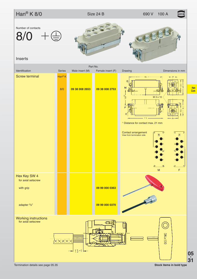
Han® K 8/0 690 V 100 A
M F
09 99 000 0363
09 99 000 0370
Screw terminal Han® K
8/0 09 38 008 2653 09 38 008 2753
Part No.
Identification Series Male insert (M) Female insert (F) Drawing Dimensions in mm
Inserts
Number of contacts
8/0
1) Distance for contact max. 21 mm
Contact arrangement View from termination side
Stock items in bold type
Working instructionsfor axial setscrew
Size 24 B
Termination details see page 05.35
with grip
adapter 3/8”
Hex Key SW 4for axial setscrew

05.32
HanCom
Standard Hoods/Housings with 2 levers on the housing Size 24 B
Part No.
Identification Low construction High construction M Drawing Dimensions in mm
Hoodsside-entry
19 30 024 1521 2519 30 024 1522 32
19 30 024 0527 3219 30 024 0528 40
Hoodstop-entry
19 30 024 1422 19 30 024 0427 32
19 30 024 0428 40
Protection covers for hoodsthermoplastic/metal 09 30 024 5401
09 30 024 5422
Housing bulkhead mounting
09 30 024 0301 –
Housingssurface 1 side-entry 19 30 024 1231 25mounting 19 30 024 0232 32
2 side-entries 19 30 024 1271 2519 30 024 0272 3219 30 024 0273 40
Protection coversfor housings bulkhead/surface mountingthermoplastic/metal 09 30 024 5405
09 30 024 5425
Hoods cable to cable
19 30 024 1732 19 30 024 0737 3219 30 024 0738 40
Hou
sing
sH
oods
Panel cut out 108 x 35 mm
Blind way for one cable entryh
Low construction 56High construction 81
hLow construction 57.5High construction 78.5
Protection coverfor hoodsmetal 09 30 024 5426
Stock items in bold type

05.33
HanCom
Standard Hoods/Housings with 1 lever on the housing Size 24 B
Part No.
Identification Low construction High construction M Drawing Dimensions in mm
Hoodsside-entry
19 30 024 1541 2519 30 024 1542 32
19 30 024 0547 3219 30 024 0548 40
Hoodstop-entry
19 30 024 1442 19 30 024 0447 32
19 30 024 0448 40
Housingsbulkhead mounting
09 30 024 0307 –
with thermo-plastic cover
09 30 024 0304 –
with metalcover
09 30 024 0318 –
Housings 1 side-entry 19 30 024 1251 25
2 side-entries 19 30 024 1291 2519 30 024 0292 32
with thermoplastic cover1 side-entry 19 30 024 1256 25
with thermoplastic cover with thermoplastic cover2 side-entries 19 30 024 1296 25
19 30 024 0297 32
with metal cover2 side-entries 19 30 024 2296 25
19 30 024 7297 32
Hoods cable to cable
19 30 024 1752 19 30 024 0757 32
Hou
sing
sH
oods
Panel cut out 108 x 35 mm
hLow construction 56High construction 81
Stock items in bold type
hLow construction 57.5High construction 78.5
1) Blind way for one cable entry

05.34
HanCom
Hoods/Housings with 1 lever on the housing for 2 inserts Size 48 B
Identification Part No. M Drawing Dimensions in mm
Hoodsside-entry
19 30 048 0548 4019 30 048 0549 50
Housingsbulkhead mounting
with thermo-plastic cover
09 30 048 0301 –
with metal cover
09 30 048 0317 –
Hou
sing
sH
oods
Hoodstop-entry
19 30 048 0448 4019 30 048 0449 50
Housingssurface mounting 2 side-entries
19 30 048 0292 2 x 3219 30 048 0293 2 x 40
with thermo-plastic cover
19 30 048 0298 2 x 40
1) Blind grommet
Panel cut out
Stock items in bold type
05.35
HanCom
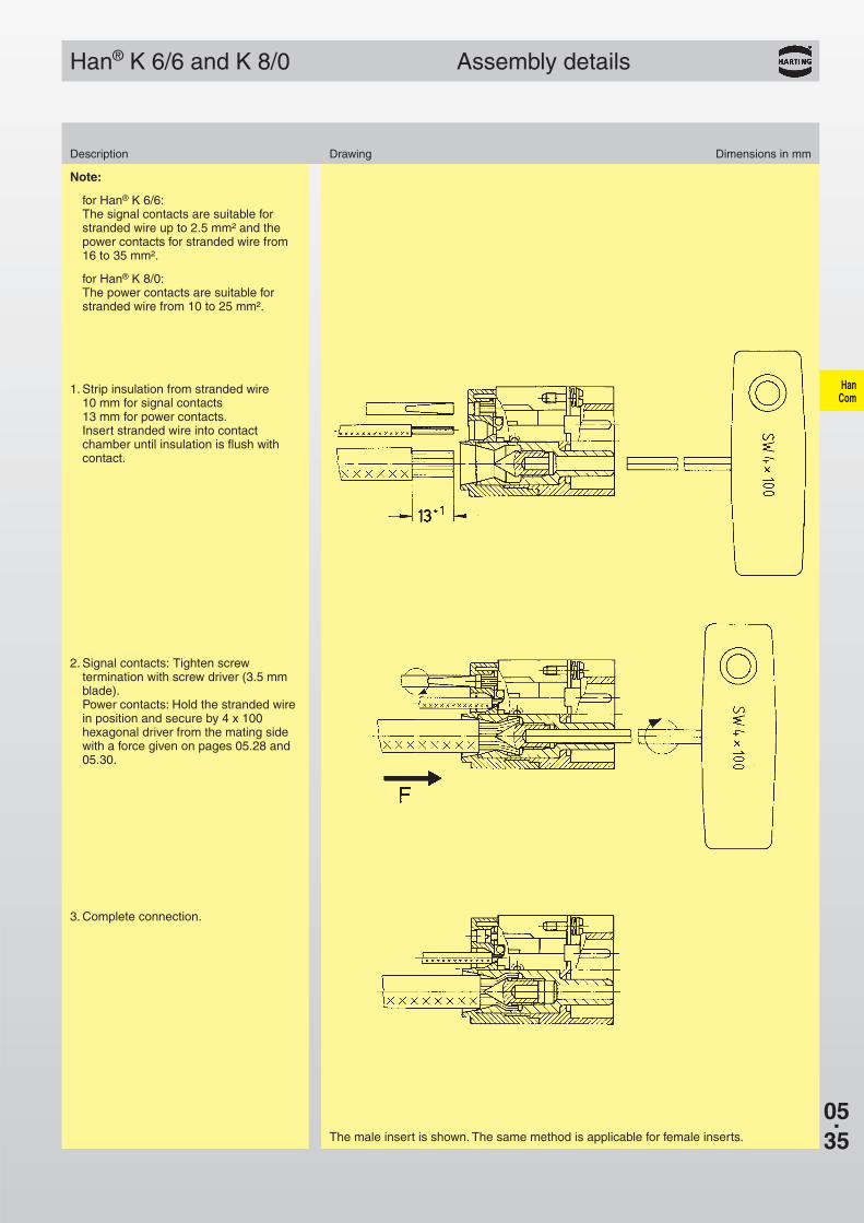
Han® K 6/6 and K 8/0 Assembly details
Description Drawing Dimensions in mm
The male insert is shown. The same method is applicable for female inserts.
Note:
for Han® K 6/6:The signal contacts are suitable forstranded wire up to 2.5 mm² and thepower contacts for stranded wire from16 to 35 mm².
for Han® K 8/0:The power contacts are suitable forstranded wire from 10 to 25 mm².
1. Strip insulation from stranded wire10 mm for signal contacts13 mm for power contacts.Insert stranded wire into contactchamber until insulation is flush withcontact.
2. Signal contacts: Tighten screw termination with screw driver (3.5 mmblade).Power contacts: Hold the stranded wirein position and secure by 4 x 100hexagonal driver from the mating sidewith a force given on pages 05.28 and05.30.
3. Complete connection.
05.36
HanCom
Notes