Embed Size (px)
Citation preview
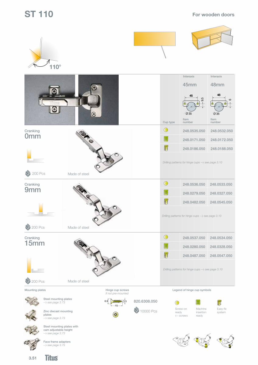
3.51
248.0536.050
248.0279.050
248.0482.050
248.0537.050
248.0280.050
248.0487.050
248.0532.050
248.0172.050
248.0188.050
248.0534.050
248.0328.050
248.0547.050
248.0535.050
248.0171.050
248.0186.050
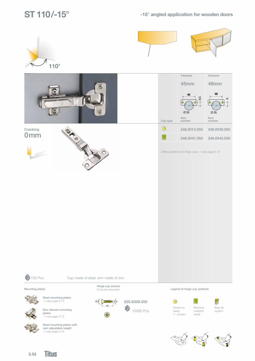
0mm
110°
9mm
15mm
45
Ø 35
9.5
48
Ø 35
6
45mm 48mm
248.0533.050
248.0327.050
248.0545.050
Cup typeItem number
Item number
Cranking
ST 110 For wooden doors
Made of steel
Made of steel
Made of steel
200 Pcs
200 Pcs
200 Pcs
820.6308.050
Hinge cup screwsIf not pre-mounted
10000 Pcs
Cranking
Cranking
InteraxisInteraxis
Screw-onready< screws
Machine insertion ready
Easy-fixsystem
Legend of hinge cup symbolsMounting plates
Steel mounting plates> see page 3.73
Face frame adapters> see page 3.75
Zinc diecast mounting plates> see page 3.73
Steel mounting plates with cam adjustable height> see page 3.73
Drilling patterns for hinge cups > see page 3.10
Drilling patterns for hinge cups > see page 3.10
Drilling patterns for hinge cups > see page 3.10
6.9
15
3.5
6.9
15
3.5
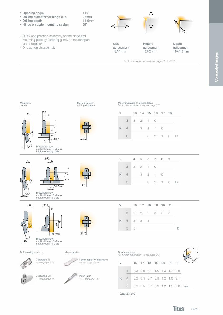
3.52
S17.8
D
7
37
3763
F>Fminx
V
K zz
S26.7
D
16
37
3763
F>2Fminx
V
KK
S 35.7
D
25
37+V
3763
F>Fmin
S17.8
D
7
37
3763
F>Fminx
V
K z
z
S26.7
D
16
37
3763
F>2Fminx
V
K
K
S 35.7
D
25
37+V
3763
F>Fmin
x 13 14 15 16 17 18
3 3 2 1 0 K 4 3 2 1 0 5 3 2 1 0 D
x 4 5 6 7 8 9
3 3 2 1 0 K 4 3 2 1 0 5 3 2 1 0 D
V 16 17 18 19 20 21
3 2 2 2 3 3 3 K 4 3 3 3 5 3 D
Con
ceal
ed h
inge
s
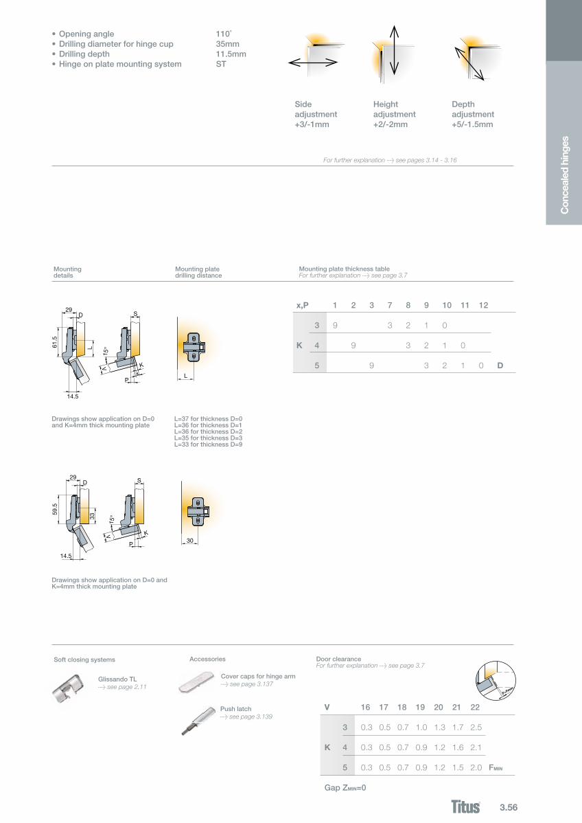
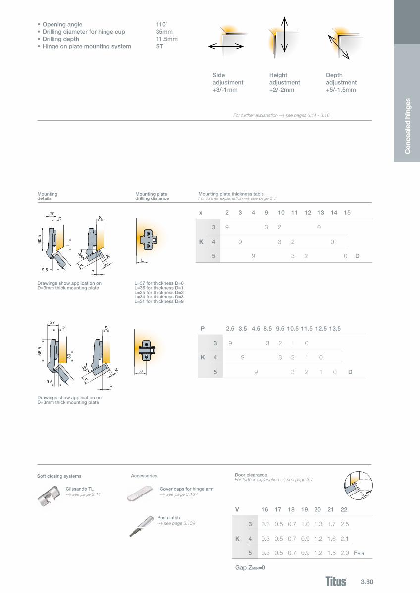
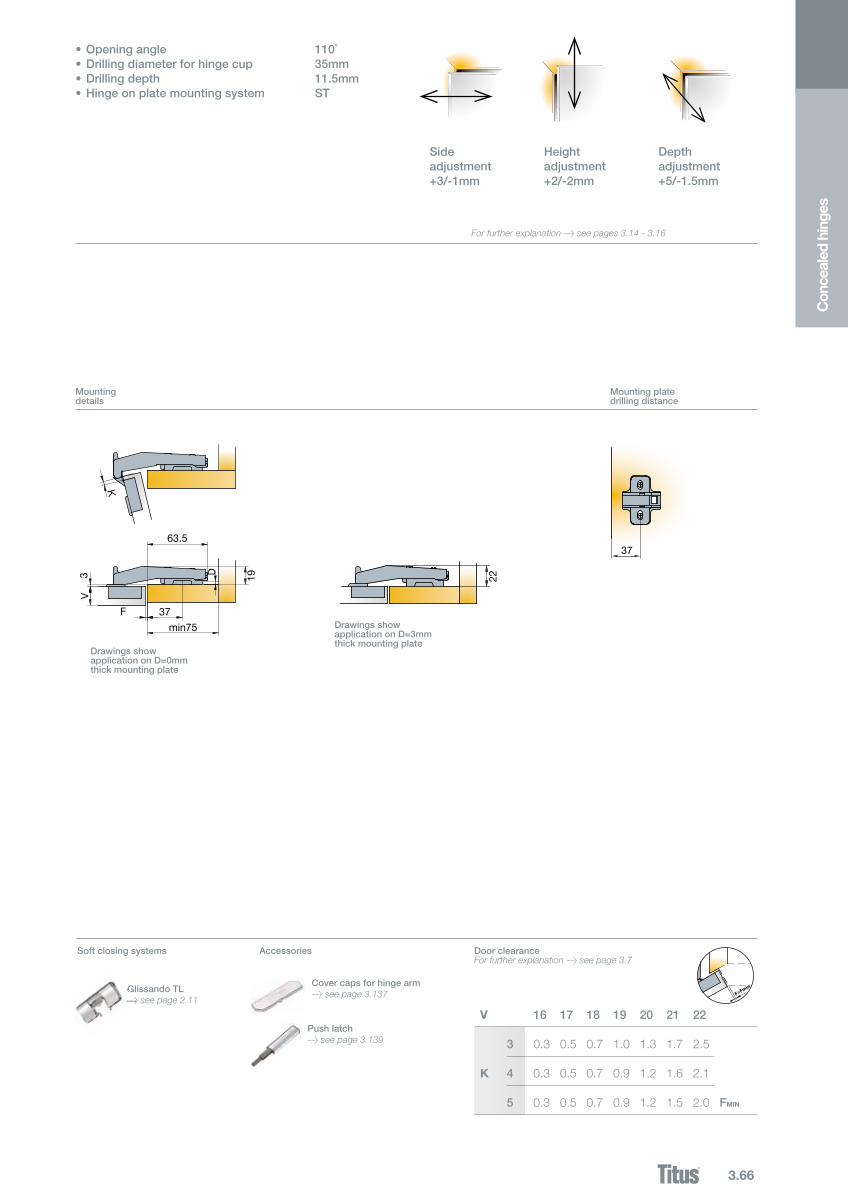
•Openingangle 110˚•Drillingdiameterforhingecup 35mm•Drillingdepth 11.5mm•Hingeonplatemountingsystem ST
· Quick and practical assembly on the hinge and mounting plate by pressing gently on the rear part of the hinge arm
· One button disassembly
Mountingdetails
Mounting plate thickness tableFor further explanation > see page 3.7
Mounting platedrilling distance
DrawingsshowapplicationonD=0mmthick mounting plate
DrawingsshowapplicationonD=0mmthick mounting plate
DrawingsshowapplicationonD=3mmthick mounting plate
DoorclearanceFor further explanation > see page 3.7
V 16 17 18 19 20 21 22
3 0.3 0.5 0.7 1.0 1.3 1.7 2.5 K 4 0.3 0.5 0.7 0.9 1.2 1.6 2.1 5 0.3 0.5 0.7 0.9 1.2 1.5 2.0 FMIN
Gap ZMIN=0
Soft closing systems Accessories
Sideadjustment+3/-1mm
Heightadjustment+2/-2mm
Depthadjustment+5/-1.5mm
F>Fmin
For further explanation > see pages 3.14 - 3.16
Cover caps for hinge arm > see page 3.137
Push latch> see page 3.139
Glissando CR> see page 2.15
GlissandoTL> see page 2.11
3.53
248.0V39.050
248.0V42.050
248.0V14.050
248.0V41.0500 mm
110°
45
Ø 35
9.5
48
Ø 35
6
45mm 48mm
110 deg
110 deg
alCE 191.3 Tf
100 Pcs
Cup typeItem number
Item number
Cranking
ST 110/-15° -15° angled application for wooden doors
820.6308.0506.9
15
3.5
6.9
15
3.5
Hinge cup screwsIf not pre-mounted
10000 Pcs
Cup made of steel, arm made of zinc
InteraxisInteraxis
Screw-onready< screws
Machine insertion ready
Easy-fixsystem
Legend of hinge cup symbolsMounting plates
Steel mounting plates> see page 3.73
Zinc diecast mounting plates> see page 3.73
Steel mounting plates with cam adjustable height> see page 3.73
Drilling patterns for hinge cups > see page 3.10
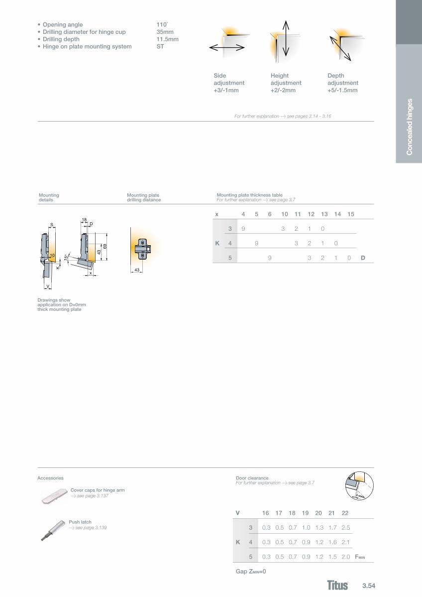
3.54
S18
D
K
69
10
V
43
43x
15°
F>Fmin
S18
D
K
69
10
V
43
43x
15°
x 4 5 6 10 11 12 13 14 15
3 9 3 2 1 0 K 4 9 3 2 1 0 5 9 3 2 1 0 D
Push latch> see page 3.139
Con
ceal
ed h
inge
s
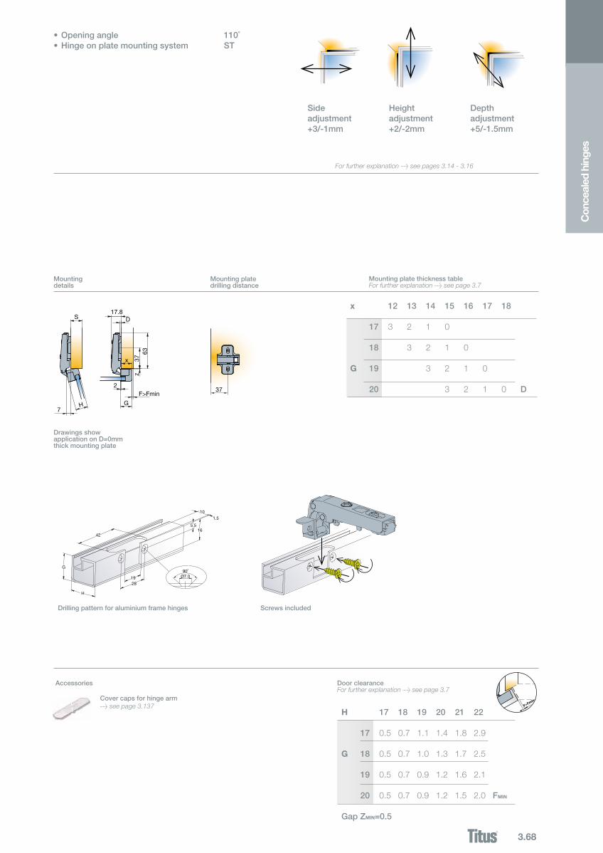
Mountingdetails
Mounting platedrilling distance
Mounting plate thickness tableFor further explanation > see page 3.7
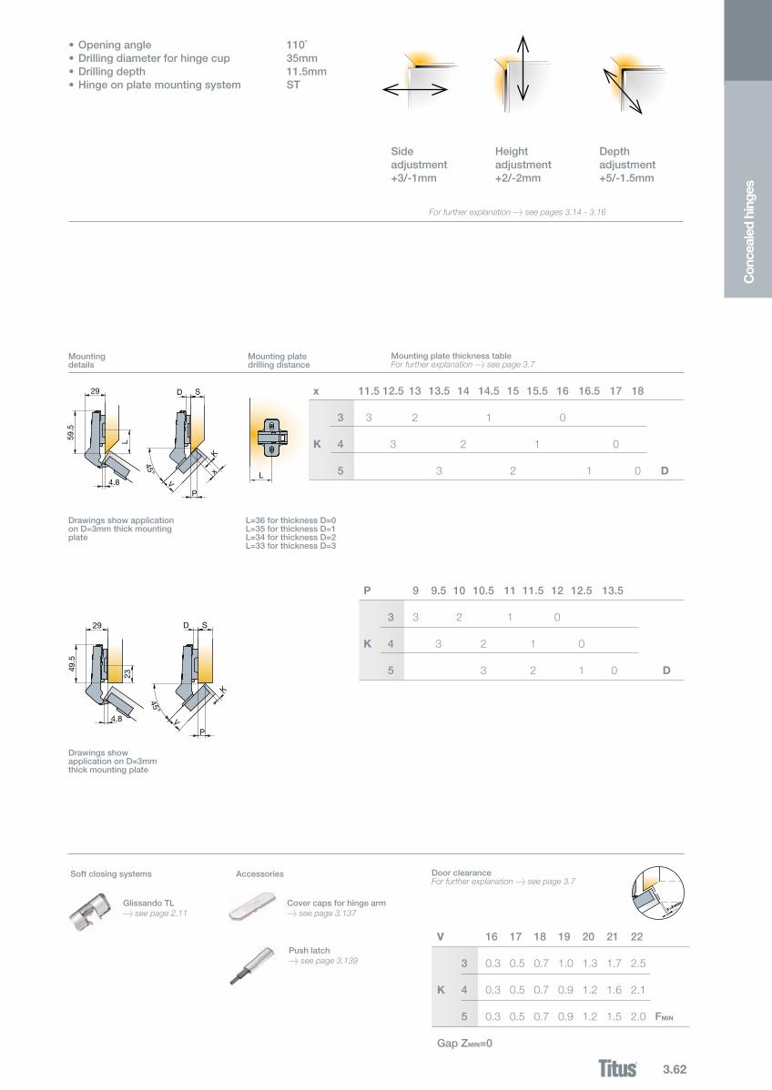
•Openingangle 110˚•Drillingdiameterforhingecup 35mm•Drillingdepth 11.5mm•Hingeonplatemountingsystem ST
Sideadjustment+3/-1mm
Heightadjustment+2/-2mm
Depthadjustment+5/-1.5mm
DoorclearanceFor further explanation > see page 3.7
V 16 17 18 19 20 21 22
3 0.3 0.5 0.7 1.0 1.3 1.7 2.5 K 4 0.3 0.5 0.7 0.9 1.2 1.6 2.1 5 0.3 0.5 0.7 0.9 1.2 1.5 2.0 FMIN
Gap ZMIN=0
DrawingsshowapplicationonD=0mmthick mounting plate
Accessories
For further explanation > see pages 3.14 - 3.16
Cover caps for hinge arm > see page 3.137
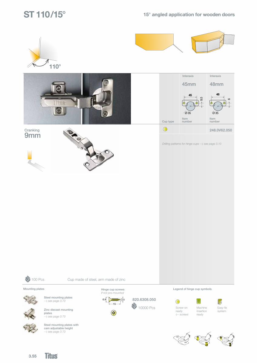
3.55
248.0V62.050
9mm
110°
45
Ø 35
9.5
48
Ø 35
6
ST 110/15°
45mm 48mm
Screw-onready< screws
Machine insertion ready
Easy-fixsystem
Legend of hinge cup symbols
100 Pcs
Cup typeItem number
Item number
Cranking
15° angled application for wooden doors
Hinge cup screwsIf not pre-mounted
10000 Pcs
Cup made of steel, arm made of zinc
InteraxisInteraxis
Mounting plates
Steel mounting plates> see page 3.73
Zinc diecast mounting plates> see page 3.73
Steel mounting plates with cam adjustable height> see page 3.73
Drilling patterns for hinge cups > see page 3.10
820.6308.0506.9
15
3.5
6.9
15
3.5
3.56
F>Fmin
x,P 1 2 3 7 89 10 11 12
3 9 3 2 1 0 K 4 9 3 2 1 0 5 9 3 2 1 0 D
x
V V
S29
D
L61.5
14.5
PL
K
14.5
P
K30
S29D
59.5
33
15°
15°
x
V V
S29
D
L61.5
14.5
PL
K
14.5
P
K30
S29D
59.5
33
15°
15°
Push latch> see page 3.139
Con
ceal
ed h
inge
s
Mountingdetails
Mounting platedrilling distance
Mounting plate thickness tableFor further explanation > see page 3.7
•Openingangle 110˚•Drillingdiameterforhingecup 35mm•Drillingdepth 11.5mm•Hingeonplatemountingsystem ST
Sideadjustment+3/-1mm
Heightadjustment+2/-2mm
Depthadjustment+5/-1.5mm
DoorclearanceFor further explanation > see page 3.7
V 16 17 18 19 20 21 22
3 0.3 0.5 0.7 1.0 1.3 1.7 2.5 K 4 0.3 0.5 0.7 0.9 1.2 1.6 2.1 5 0.3 0.5 0.7 0.9 1.2 1.5 2.0 FMIN
Gap ZMIN=0
DrawingsshowapplicationonD=0and K=4mm thick mounting plate
L=37forthicknessD=0L=36forthicknessD=1L=36forthicknessD=2L=35forthicknessD=3L=33forthicknessD=9
DrawingsshowapplicationonD=0andK=4mm thick mounting plate
Soft closing systems
GlissandoTL> see page 2.11
Accessories
For further explanation > see pages 3.14 - 3.16
Cover caps for hinge arm > see page 3.137
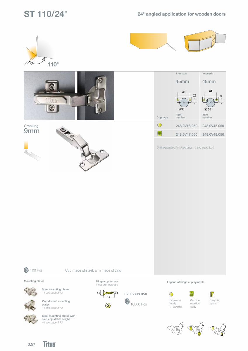
3.57
248.0V45.050
248.0V48.050
248.0V18.050
248.0V47.0509mm
110°
45
Ø 35
9.5
48
Ø 35
6
45mm 48mm
100 Pcs
Cup typeItem number
Item number
Cranking
ST 110/24° 24° angled application for wooden doors
820.6308.050
Hinge cup screwsIf not pre-mounted
10000 Pcs
Cup made of steel, arm made of zinc
Screw-onready< screws
Machine insertion ready
Easy-fixsystem
Legend of hinge cup symbols
InteraxisInteraxis
Mounting plates
Steel mounting plates> see page 3.73
Zinc diecast mounting plates> see page 3.73
Steel mounting plates with cam adjustable height> see page 3.73
Drilling patterns for hinge cups > see page 3.10
6.9
15
3.5
6.9
15
3.5

3.58
24°
8
S24.5
D
37
3763
.5
K
xV
24°
8
S24.5
D
37
3763
.5
K
xV
F>Fmin
x 3 4 5 9 10 11 12 13 14
3 9 3 2 1 0 K 4 9 3 2 1 0 5 9 3 2 1 0 D
Push latch> see page 3.139
Con
ceal
ed h
inge
s
Mountingdetails
Mounting platedrilling distance
Mounting plate thickness tableFor further explanation > see page 3.7
DrawingsshowapplicationonD=0mmthickmountingplate
•Openingangle 110˚•Drillingdiameterforhingecup 35mm•Drillingdepth 11.5mm•Hingeonplatemountingsystem ST
Sideadjustment+3/-1mm
Heightadjustment+2/-2mm
Depthadjustment+5/-1.5mm
DoorclearanceFor further explanation > see page 3.7
V 16 17 18 19 20 21 22
3 0.3 0.5 0.7 1.0 1.3 1.7 2.5 K 4 0.3 0.5 0.7 0.9 1.2 1.6 2.1 5 0.3 0.5 0.7 0.9 1.2 1.5 2.0 FMIN
Gap ZMIN=0
Soft closing systems
GlissandoTL> see page 2.11
Accessories
For further explanation > see pages 3.14 - 3.16
>
Cover caps for hinge arm > see page 3.137
3.59
248.0665.050
248.0N13.050
248.0675.050
248.0N12.0509mm
110°
45
Ø 35
9.5
48
Ø 35
6
45mm 48mm
ST 110/30°
200 Pcs
Cup typeItem number
Item number
Cranking
30° angled application for wooden doors
820.6308.050
Hinge cup screwsIf not pre-mounted
10000 Pcs
Cup made of steel, arm made of zinc
Screw-onready< screws
Machine insertion ready
Easy-fixsystem
Legend of hinge cup symbols
InteraxisInteraxis
Mounting plates
Steel mounting plates> see page 3.73
Zinc diecast mounting plates> see page 3.73
Steel mounting plates with cam adjustable height> see page 3.73
Drilling patterns for hinge cups > see page 3.10
6.9
15
3.5
6.9
15
3.5
3.60
S27
D
9.5
L
60.5
L
P
K
x
30°V
S27
D
9.5
L
60.5
L
P
K
x
30°V
S27
D
9.5
L
60.5
30
P
K
x
30°V
S27
D
9.5
30
56.5
P
K
30°
F>Fmin
x 2 3 4 9 10 11 12 13 14 15
3 9 3 2 0 K 4 9 3 2 0 5 9 3 2 0 D
P 2.5 3.5 4.5 8.5 9.5 10.511.5 12.513.5
3 9 3 2 1 0 K 4 9 3 2 1 0 5 9 3 2 1 0 D
Push latch> see page 3.139
Con
ceal
ed h
inge
s
Mountingdetails
Mounting plate thickness tableFor further explanation > see page 3.7
DrawingsshowapplicationonD=3mmthickmountingplate
L=37forthicknessD=0L=36forthicknessD=1L=35forthicknessD=2L=34forthicknessD=3L=31forthicknessD=9
DrawingsshowapplicationonD=3mmthickmountingplate
Mounting platedrilling distance
DoorclearanceFor further explanation > see page 3.7
V 16 17 18 19 20 21 22
3 0.3 0.5 0.7 1.0 1.3 1.7 2.5 K 4 0.3 0.5 0.7 0.9 1.2 1.6 2.1 5 0.3 0.5 0.7 0.9 1.2 1.5 2.0 FMIN
Gap ZMIN=0
•Openingangle 110˚•Drillingdiameterforhingecup 35mm•Drillingdepth 11.5mm•Hingeonplatemountingsystem ST
Sideadjustment+3/-1mm
Heightadjustment+2/-2mm
Depthadjustment+5/-1.5mm
Legend of hinge cup symbols Soft closing systems
GlissandoTL> see page 2.11
Accessories
For further explanation > see pages 3.14 - 3.16
>Cover caps for hinge arm > see page 3.137

3.61
248.0431.050
248.0N17.050
248.0433.050
248.0N16.0509mm
110°
45
Ø 35
9.5
48
Ø 35
6
45mm 48mm
ST 110/45°
Cup typeItem number
Item number
Cranking
45° angled application for wooden doors
200 Pcs Cup made of steel, arm made of zinc
820.6308.050
Hinge cup screwsIf not pre-mounted
10000 PcsScrew-onready< screws
Machine insertion ready
Easy-fixsystem
Legend of hinge cup symbols
InteraxisInteraxis
Mounting plates
Steel mounting plates> see page 3.73
Zinc diecast mounting plates> see page 3.73
Steel mounting plates with cam adjustable height> see page 3.73
Drilling patterns for hinge cups > see page 3.10
6.9
15
3.5
6.9
15
3.5
3.62
V
S29 D
4.8
L59.5
L
P
K
x
45°
V
S29 D
4.8
L59.5
L
P
K
x
45°
V
S29 D
4.8
23
49.5
P
K
45°
F>Fmin
x 11.512.5 13 13.5 14 14.5 15 15.5 16 16.5 17 18
3 3 2 1 0 K 4 3 2 1 0 5 3 2 1 0 D
P 9 9.5 10 10.5 11 11.5 12 12.5 13.5
3 3 2 1 0 K 4 3 2 1 0 5 3 2 1 0 D
Push latch> see page 3.139
Con
ceal
ed h
inge
s
Mountingdetails
Mounting platedrilling distance
Mounting plate thickness tableFor further explanation > see page 3.7
L=36forthicknessD=0L=35forthicknessD=1L=34forthicknessD=2L=33forthicknessD=3
DrawingsshowapplicationonD=3mmthickmountingplate
DrawingsshowapplicationonD=3mmthick mounting plate
DoorclearanceFor further explanation > see page 3.7
V 16 17 18 19 20 21 22
3 0.3 0.5 0.7 1.0 1.3 1.7 2.5 K 4 0.3 0.5 0.7 0.9 1.2 1.6 2.1 5 0.3 0.5 0.7 0.9 1.2 1.5 2.0 FMIN
Gap ZMIN=0
•Openingangle 110˚•Drillingdiameterforhingecup 35mm•Drillingdepth 11.5mm•Hingeonplatemountingsystem ST
Sideadjustment+3/-1mm
Heightadjustment+2/-2mm
Depthadjustment+5/-1.5mm
GlissandoTL> see page 2.11
AccessoriesSoft closing systems
For further explanation > see pages 3.14 - 3.16
>Cover caps for hinge arm > see page 3.137

3.63
248.0283.050
248.0N21.050
248.0285.050
248.0N20.05018mm
110°
45
Ø 35
9.5
48
Ø 35
6
45mm 48mm
ST 110/45° 45° angled application for wooden doors
100 Pcs
Cup typeItem number
Item number
Cranking
Cup made of steel, arm made of zinc
820.6308.050
Hinge cup screwsIf not pre-mounted
10000 PcsScrew-onready< screws
Machine insertion ready
Easy-fixsystem
Legend of hinge cup symbols
InteraxisInteraxis
Mounting plates
Steel mounting plates> see page 3.73
Face frame adapters> see page 3.75
Zinc diecast mounting plates> see page 3.73
Steel mounting plates with cam adjustable height> see page 3.73
Drilling patterns for hinge cups > see page 3.10
6.9
15
3.5
6.9
15
3.5
3.64
V
S39 D
15
63.5
37K45°
37
V
S39 D
15
63.5
37K45°
37
D=1
8
48
1957
K
4874
.5
1945º
D=1
8
48
1957
K
4874
.5
19
45º
F>Fmin
K 3 4 5
D 0 1 2
Push latch> see page 3.139
Con
ceal
ed h
inge
s
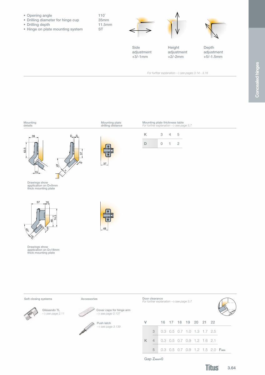
•Openingangle 110˚•Drillingdiameterforhingecup 35mm•Drillingdepth 11.5mm•Hingeonplatemountingsystem ST
Sideadjustment+3/-1mm
Heightadjustment+2/-2mm
Depthadjustment+5/-1.5mm
Mountingdetails
Mounting plate thickness tableFor further explanation > see page 3.7
Mounting platedrilling distance
DoorclearanceFor further explanation > see page 3.7
V 16 17 18 19 20 21 22
3 0.3 0.5 0.7 1.0 1.3 1.7 2.5 K 4 0.3 0.5 0.7 0.9 1.2 1.6 2.1 5 0.3 0.5 0.7 0.9 1.2 1.5 2.0 FMIN
Gap ZMIN=0
DrawingsshowapplicationonD=18mmthick mounting plate
DrawingsshowapplicationonD=0mmthick mounting plate
GlissandoTL> see page 2.11
AccessoriesSoft closing systems
For further explanation > see pages 3.14 - 3.16
>Cover caps for hinge arm > see page 3.137
3.65
248.0742.050
248.0N25.050
248.0N62.050
248.0745.050
248.0N24.050
248.0L61.050
18mm
110°
45
Ø 35
9.5
48
Ø 35
6
45mm 48mm
ST 110/90°
110 deg
110 deg
alCE 191.3 Tf
For wooden door cabinets with blind panels
Cranking
100 Pcs Cup made of steel, arm made of zinc
Cup typeItem number
Item number
820.6308.0506.9
15
3.5
6.9
15
3.5
Hinge cup screwsIf not pre-mounted
10000 Pcs
Screw-onready< screws
Machine insertion ready
Easy-fixsystem
Legend of hinge cup symbols
InteraxisInteraxis
Mounting plates
Steel mounting plates> see page 3.73
Face frame adapters> see page 3.75
Zinc diecast mounting plates> see page 3.73
Steel mounting plates with cam adjustable height> see page 3.73
Drilling patterns for hinge cups > see page 3.10
3.66
K
V
F 37
3
63.5
19D
37
min75
K
V
F 37
3
63.5
19D
37
min75
V 16 17 18 19 20 21 22
3 0.3 0.5 0.7 1.0 1.3 1.7 2.5 K 4 0.3 0.5 0.7 0.9 1.2 1.6 2.1 5 0.3 0.5 0.7 0.9 1.2 1.5 2.0 FMIN
2122
1
Push latch> see page 3.139
Con
ceal
ed h
inge
s
Mountingdetails
Mounting platedrilling distance
DrawingsshowapplicationonD=0mmthick mounting plate
DoorclearanceFor further explanation > see page 3.7
•Openingangle 110˚•Drillingdiameterforhingecup 35mm•Drillingdepth 11.5mm•Hingeonplatemountingsystem ST
Sideadjustment+3/-1mm
Heightadjustment+2/-2mm
Depthadjustment+5/-1.5mm
DrawingsshowapplicationonD=3mmthick mounting plate
GlissandoTL> see page 2.11
AccessoriesSoft closing systems
F>Fmin
For further explanation > see pages 3.14 - 3.16
GlissandoTL>
Cover caps for hinge arm > see page 3.137
3.67
950.0T27.050
0mm
110°
19
28
28mm
ST 110 For aluminium frame doors
Cranking
200 Pcs
Cup typeItem number
Cup made of zinc, arm made of steel
Interaxis
Mounting plates
Steel mounting plates> see page 3.73
Face frame adapters> see page 3.75
Zinc diecast mounting plates> see page 3.73
Steel mounting plates with cam adjustable height> see page 3.73
3.68
S17.8
D
7
37
3763
F>Fmin
G
2
H
x
z
S17.8
D
7
37
3763
F>Fmin
G
2
H
x
z
x 12 13 14 15 16 17 18
17 3 2 1 0
18 3 2 1 0 G 19 3 2 1 0 20 3 2 1 0 D
G
H
1928
42
5.516
1.5
10
90˚Ø7.0
Con
ceal
ed h
inge
s
•Openingangle 110˚•Hingeonplatemountingsystem ST
Sideadjustment+3/-1mm
Heightadjustment+2/-2mm
Depthadjustment+5/-1.5mm
Mountingdetails
Mounting plate thickness tableFor further explanation > see page 3.7
Mounting platedrilling distance
DrawingsshowapplicationonD=0mmthick mounting plate
DoorclearanceFor further explanation > see page 3.7
H 17 18 19 20 21 22
17 0.5 0.7 1.1 1.4 1.8 2.9 G 18 0.5 0.7 1.0 1.3 1.7 2.5 19 0.5 0.7 0.9 1.2 1.6 2.1
20 0.5 0.7 0.9 1.2 1.5 2.0 FMIN
Gap ZMIN=0.5
Screws includedDrillingpatternforaluminiumframehinges
Cover caps for hinge arm> see page 3.137
Accessories
F>Fmin
For further explanation > see pages 3.14 - 3.16
3.69
248.0R17.050
248.0R13.050
248.0R14.050
248.0M73.0500mm
0mm
9mm
135°-165°
45
Ø 35
9.5
48
Ø 35
6
45mm 48mm
248.0R18.050 *248.0V65.050
*248.0S69.050
248.0162.050 248.0163.050
ST 170 For wooden doors
Made of steel and zinc
Made of steel and zinc
Made of steel and zinc
Legend of hinge cup symbols
Screw-onready< screws
Machine insertion ready
50 Pcs
Cup typeItem number
Item number
Cranking
Drilling patterns for hinge cups > see page 3.10
* Available upon special request > see page 0.3
Cranking
Cranking
50 Pcs
50 Pcs
820.6308.050
Hinge cup screwsIf not pre-mounted
10000 Pcs
Adjustable opening angle
InteraxisInteraxis
Mounting plates
Steel mounting plates> see page 3.73
Face frame adapters> see page 3.75
Zinc diecast mounting plates> see page 3.73
Steel mounting plates with cam adjustable height> see page 3.73
With adjustable opening angle
Drilling patterns for hinge cups > see page 3.10
Drilling patterns for hinge cups > see page 3.10
6.9
15
3.5
6.9
15
3.5
3.70
37
C
52D
7
37
67
F>Fmin
19
19K
1.4
90°
37
C
52D
7
37
67
F>Fmin
19
19K
1.4
90°
X 10 11 12 13 14 15 16 17 18 19 20
3 6 5 4 3 2 1 0 K 4 6 5 4 3 2 1 0 5 6 5 4 3 2 1 0
6 6 5 4 3 2 1 0
7 6 5 4 3 2 1 0 D
37
V67
F>2Fmin
D61 S
V67
70 S 79 S
V67
C
K
7.6
F>Fmin
61 19D
x 37
6719
90˚
37
V67
F>2Fmin
D61 S
V67
70 S 79 S
V67
C
K
7.6
F>Fmin
61 19D
x 37
6719
90˚
37
V67
F>2Fmin
D61 S
V67
70 S 79 S
V67
C
K
7.6
F>Fmin
61 19D
x 37
6719
90˚
37
V67
F>2Fmin
D61 S
V67
70 S 79 S
V67
C
K
7.6
F>Fmin
61 19D
x 37
6719
90˚
37
V67
F>2Fmin
D61 S
V67
70 S 79 S
V67
C
K
7.6
F>Fmin
61 19D
x 37
6719
90˚
Soft closing systems
Glissando CR> see page 2.15
Glissando170> see page 2.13
Con
ceal
ed h
inge
s
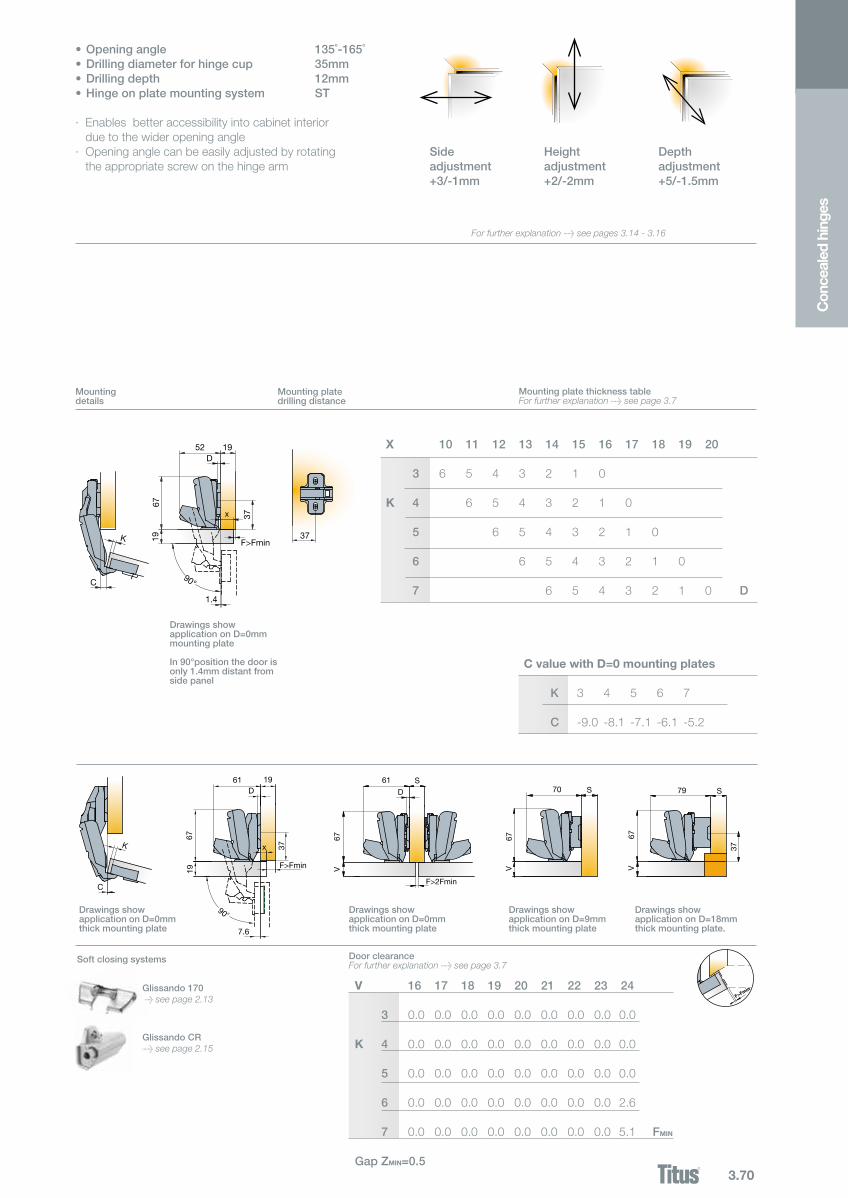
•Openingangle 135˚-165˚•Drillingdiameterforhingecup 35mm•Drillingdepth 12mm•Hingeonplatemountingsystem ST
· Enables better accessibility into cabinet interior due to the wider opening angle
· Opening angle can be easily adjusted by rotating the appropriate screw on the hinge arm
Sideadjustment+3/-1mm
Heightadjustment+2/-2mm
Depthadjustment+5/-1.5mm
Mountingdetails
Mounting platedrilling distance
Mounting plate thickness tableFor further explanation > see page 3.7
DrawingsshowapplicationonD=0mmmounting plate
In 90°position the door is only1.4mmdistantfromside panel
C value with D=0 mounting plates
K 3 4 5 6 7 C -9.0 -8.1 -7.1 -6.1 -5.2
Legend of hinge cup symbols DoorclearanceFor further explanation > see page 3.7 V 16 17 18 19 20 21 22 23 24
3 0.0 0.0 0.0 0.0 0.0 0.0 0.0 0.0 0.0 K 4 0.0 0.0 0.0 0.0 0.0 0.0 0.0 0.0 0.0 5 0.0 0.0 0.0 0.0 0.0 0.0 0.0 0.0 0.0
6 0.0 0.0 0.0 0.0 0.0 0.0 0.0 0.0 2.6
7 0.0 0.0 0.0 0.0 0.0 0.0 0.0 0.0 5.1 FMIN
Gap ZMIN=0.5
DrawingsshowapplicationonD=0mmthick mounting plate
DrawingsshowapplicationonD=9mmthick mounting plate
DrawingsshowapplicationonD=18mmthick mounting plate.
DrawingsshowapplicationonD=0mmthick mounting plate
F>Fmin
For further explanation > see pages 3.14 - 3.16
3.71
248.0U16.050
248.0V15.050
248.0U21.050
248.0U22.050
45
Ø 35
9.5
48
Ø 35
6
45mm 48mm
110 deg
110 deg
alCE 191.3 Tf
ST for pie-cut corner cabinet
For wooden doors
Cup typeItem number
Item number
Cup made of steel, arm made of zinc
Legend of hinge cup symbols
Screw-onready< screws
Machine insertion ready
100 Pcs
Cornercabinet
820.6308.050
Hinge cup screwsIf not pre-mounted
10000 Pcs
InteraxisInteraxis
Mounting plates
Steel mounting plates> see page 3.73
Zinc diecast mounting plates> see page 3.73
Steel mounting plates with cam adjustable height> see page 3.73
Drilling patterns for hinge cups > see page 3.10
6.9
15
3.5
6.9
15
3.5
3.72
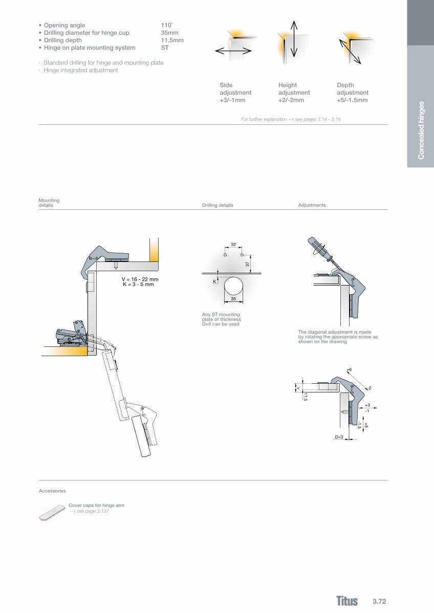
V = 16 - 22 mmK = 3 - 5 mm
K
32
35
37
D=3
+3-1
v
11.5
+6
-2
+5
-1.5
Con
ceal
ed h
inge
s
Legend of hinge cup symbols
Mountingdetails Drillingdetails Adjustments
AnySTmountingplate of thickness D=0canbeused
•Openingangle 110˚•Drillingdiameterforhingecup 35mm•Drillingdepth 11.5mm•Hingeonplatemountingsystem ST
· Standard drilling for hinge and mounting plate· Hinge integrated adjustment
Sideadjustment+3/-1mm
Heightadjustment+2/-2mm
Depthadjustment+5/-1.5mm
Thediagonaladjustmentismadeby rotating the appropriate screw as shown on the drawing
Accessories
Cover caps for hinge arm > see page 3.137
For further explanation > see pages 3.14 - 3.16
3.73
L
Ø6.3Ø8 7.5
12
4
7.5
12
4L
Ø6.3Ø8
3237
50
60
50
60
3237
3237
52
58
49
58
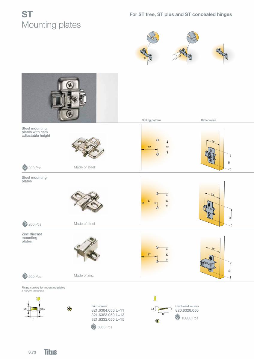
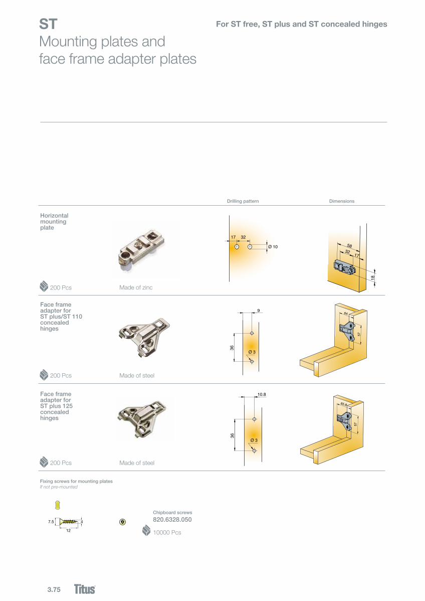
STMounting plates
For ST free, ST plus and ST concealed hinges
Drillingpattern Dimensions
200 Pcs
Zinc diecast mounting plates
200 Pcs
Steel mounting plates with cam adjustable height
Euro screws
821.6304.050L=11821.6323.050L=13821.6332.050L=15
5000 Pcs
Fixing screws for mounting platesIf not pre-mounted
Chipboard screws
820.6328.050
10000 Pcs
Steel mounting plates
Made of steel
200 Pcs Made of steel
Made of zinc
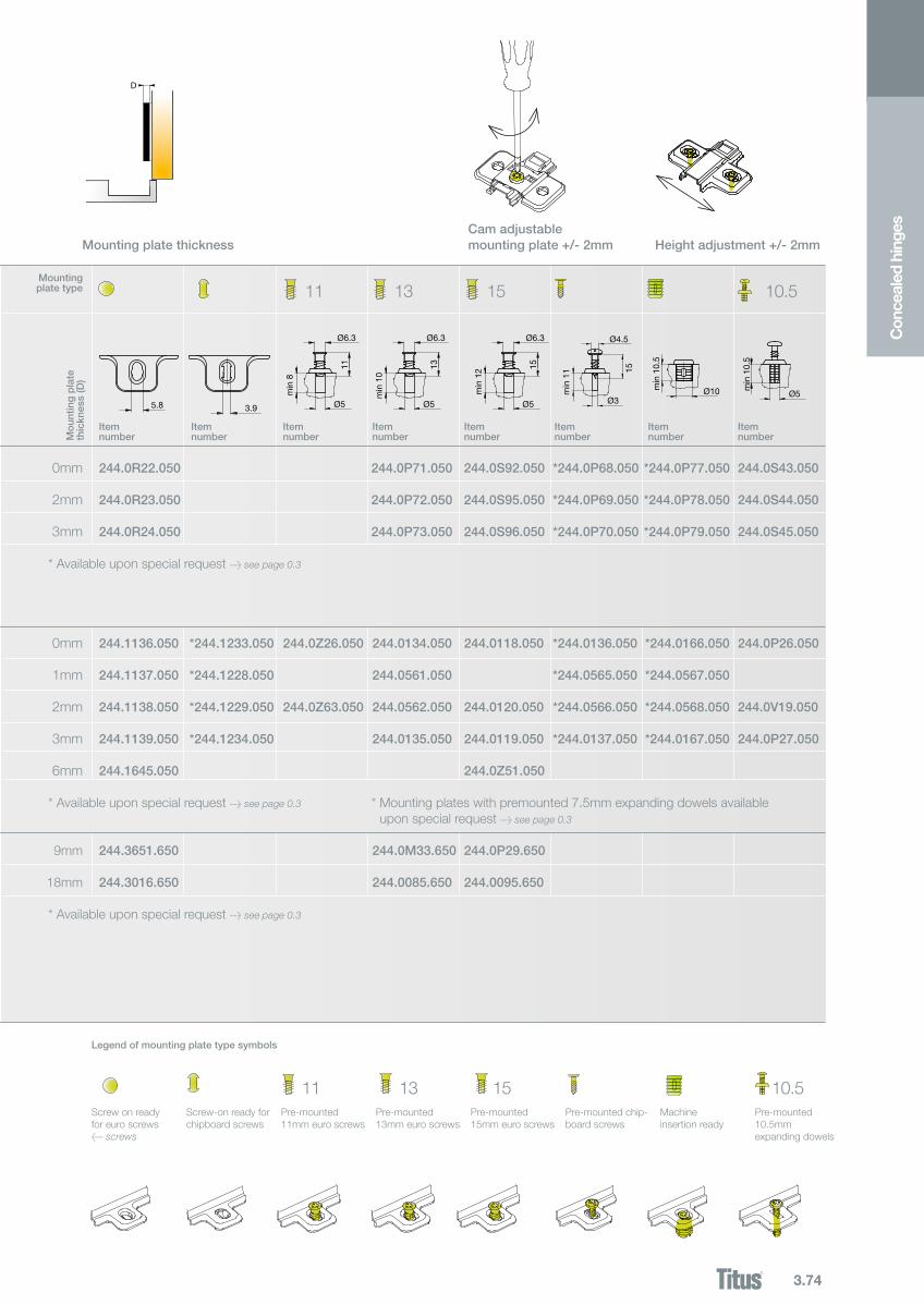
3.74
13 15 10.5
D
Z
11
Con
ceal
ed h
inge
s
Cam adjustable mounting plate +/- 2mm Height adjustment +/- 2mm
Screw on readyfor euro screws< screws
Screw-on ready for chipboard screws
Pre-mounted11mm euro screws
Pre-mounted13mm euro screws
Pre-mounted15mm euro screws
Pre-mounted chip-board screws
Machineinsertion ready
Pre-mounted10.5mm expanding dowels
Legend of mounting plate type symbols
Mounting plate thickness
15
244.3651.650
244.3016.650
5.8 Ø3
min
11
Ø4.5
15
244.0P29.650
244.0095.650
Ø5
min
12
Ø6.3
15
10.5
Ø5
min
10.
5
244.0R22.050
244.0R23.050
244.0R24.050
*244.0P68.050
*244.0P69.050
*244.0P70.050
244.0S92.050
244.0S95.050
244.0S96.050
244.0S43.050
244.0S44.050
244.0S45.050
0mm
2mm
3mm
9mm
18mm
244.1136.050
244.1137.050
244.1138.050
244.1139.050
244.1645.050
*244.0136.050
*244.0565.050
*244.0566.050
*244.0137.050
244.0118.050
244.0120.050
244.0119.050
244.0Z51.050
244.0P26.050
244.0V19.050
244.0P27.050
0mm
1mm
2mm
3mm
6mm
13
244.0M33.650
244.0085.650
244.0P71.050
244.0P72.050
244.0P73.050
244.0134.050
244.0561.050
244.0562.050
244.0135.050
Ø10min
10.
5
*244.0P77.050
*244.0P78.050
*244.0P79.050
*244.0166.050
*244.0567.050
*244.0568.050
*244.0167.050
11
Ø5
Ø6.311
min
8
244.0Z26.050
244.0Z63.050
3.9
*244.1233.050
*244.1228.050
*244.1229.050
*244.1234.050
Ø5
Ø6.3
13
min
10
Mo
untin
g p
late
thickn
ess(D)
Item number
Mountingplate type
Item number
Item number
Item number
* Available upon special request > see page 0.3
* Available upon special request > see page 0.3
* Available upon special request > see page 0.3
* Mounting plates with premounted 7.5mm expanding dowels available upon special request > see page 0.3
Item number
Item number
Item number
Item number
3.75
9
36
Ø 3
10.8
36
Ø 3
7.5
12
47.5
12
4
17 32
Ø 10 58
18
32 17
57
64
57
65.8
49
58
STMounting plates and face frame adapter plates
For ST free, ST plus and ST concealed hinges
Drillingpattern
Face frameadapter for STplus125concealedhinges
Horizontalmountingplate
Fixing screws for mounting platesIf not pre-mounted
Dimensions
Chipboard screws
820.6328.050
10000 Pcs
200 Pcs
200 Pcs
200 Pcs
Face frameadapter for STplus/ST110concealedhinges
Made of zinc
Made of steel
Made of steel
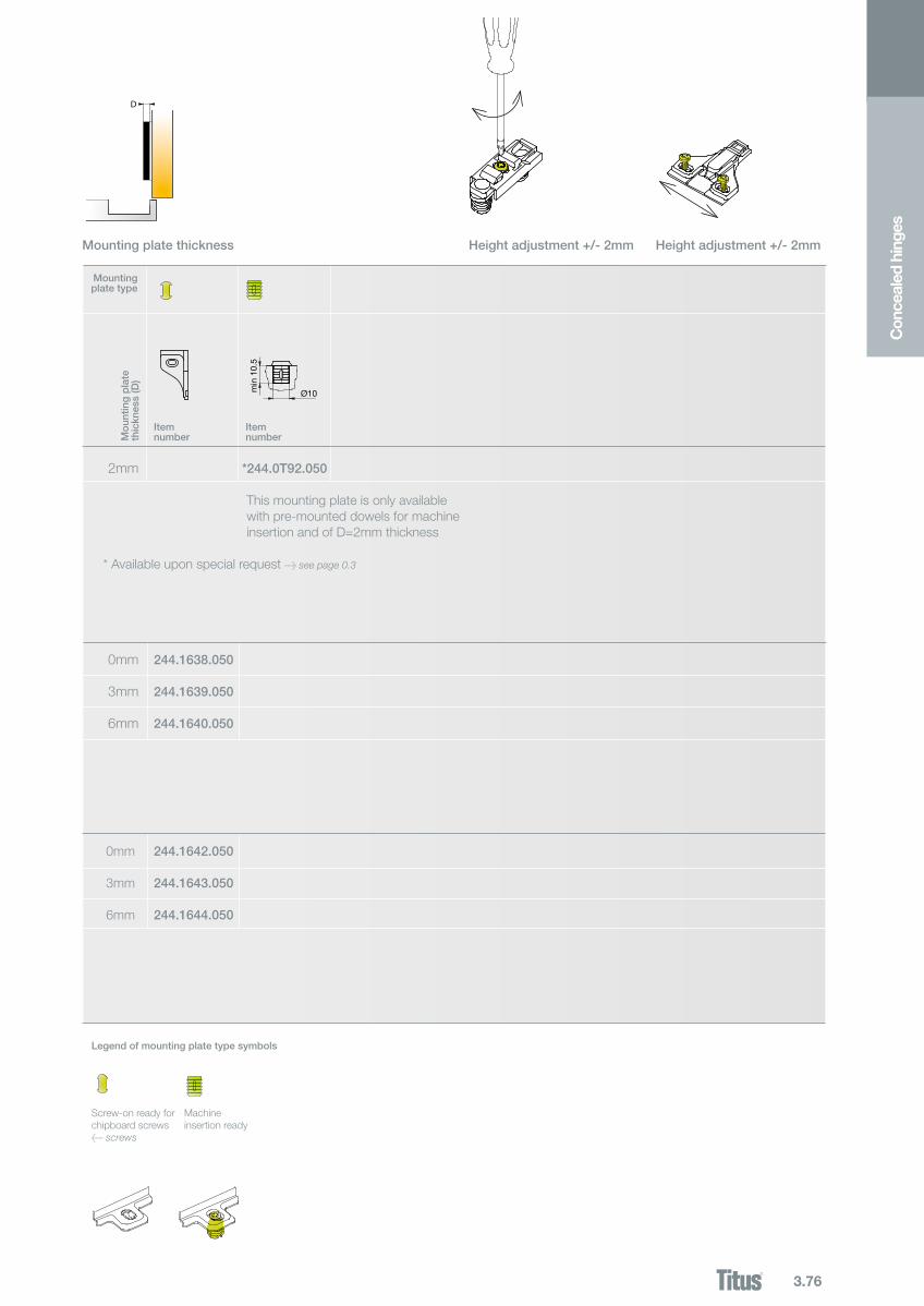
3.76
*244.0T92.050
244.1642.050
244.1643.050
244.1644.050
Ø10min
10.
5
244.1638.050
244.1639.050
244.1640.050
0mm
3mm
6mm
D
Z
0mm
3mm
6mmC
once
aled
hin
ges
Item number
Item number
Mountingplate type
2mm
Screw-on ready for chipboard screws< screws
Machineinsertion ready
Legend of mounting plate type symbols
This mounting plate is only available with pre-mounted dowels for machine insertion and of D=2mm thickness
Mo
untin
g p
late
thickn
ess(D)
Mounting plate thickness Height adjustment +/- 2mm Height adjustment +/- 2mm
* Available upon special request > see page 0.3