Embed Size (px)
Citation preview
MINI PROJECT: PULSE RATE DETECTOR
1.0 Abstract
This mini project is to design a low cost pulse rate detector by making use of
microcontroller and IR sensor. Through this mini project, we learn how to construct a
circuit to measure the pulse and to convert an analog pulse signal into digital form by
using microcontroller Analog-Digital Convertor (ADCON) and then display the pulse
value in the LCD display.
2.0 Introduction
Human pulse is detected on the radial artery at a position on our wrist. The
purpose of this project is to design a circuit for detecting human pulse with a
photodiode and later combine this circuit with microcontroller PIC18F4580 and LCD
display.
Pulse rate measurement indicates the soundness of the human cardiovascular
system. This project demonstrates a technique to measure the pulse rate by sensing
the change in blood volume in a finger artery while the heart is pumping the blood.
This project consists of an IR emitter that transmits an IR signal through the fingertip
of a person and then an IR receiver detects the reflected signal. The changing of
blood volume with heartbeat results in a train of pulses at the output of the IR
receiver. Therefore, a two-stage high gain, active low pass filter is designed using
Operational Amplifiers (Op-Amps) to filter and amplify the signal to appropriate the
level of the voltage.
2.1 Pulse
In medicine, one’s pulse represents the tactile arterial palpation of the
heartbeat by trained fingertips. The most prominent sites where in it is
relatively easy to find the pulse are wrist (radial artery), neck (carotid artery),
inside of the elbow (brachial artery), behind the knee (Popliteal artery),
Ankle joint (Posterior tibial artery). The pulse can also be measured by
listening to the heartbeat directly (auscultation), traditionally using a
ENT 373 EMBEDDED SYSTEM DESIGN AND APPLICATION Page 1
MINI PROJECT: PULSE RATE DETECTOR
stethoscope.
2.2 How to Measure Pulse Manually
Measuring pulse is easy. It requires no special equipment, only with a normal
watch with a second hand or digital second counter is very helpful.
1. Turn the palm side of your hand facing up.
2. Place your index and middle fingers of your opposite hand on your wrist,
approximately 1 inch below the base of your hand.
3. Press your fingers down in the grove between your middle tendons and
your outside bone. You should feel a throbbing, that’s your pulse!
4. Count the number of beats for 10 seconds, and then multiply the number
you calculated by 6. That will give you your heart rate for a minute.
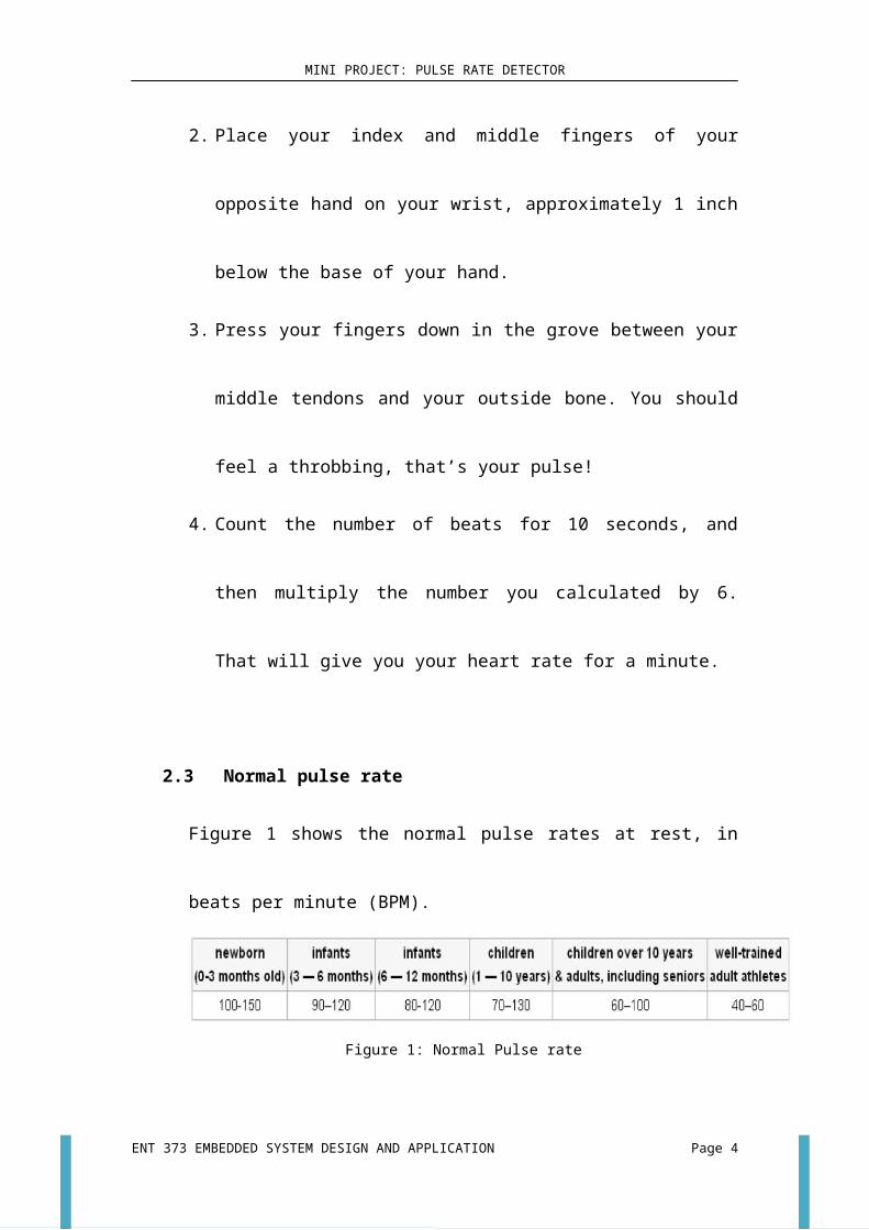
2.3 Normal pulse rate
Figure 1 shows the normal pulse rates at rest, in beats per minute (BPM).
Figure 1: Normal Pulse rate
Pulse rate detector monitors the light level transmitted through the
vascular tissue of the fingertip or the ear lobe and the corresponding
variations in light intensities that occurs as the blood volume changes in the
tissue. The average resting human heart rate for a normal range is 60 – 90
beats per minutes (bpm).
Many athletes have pulse rates in the 40 – 60 range, depending on how
fit they are. In general, a lower pulse rate is good but not a very low pulse
rate. A person with a low pulse rate is known as Bradycardia and it will cause
a person to faint.
Pulse rate also depends on the position of the body. When a person lies
down or sleeping, he/she will get a lowest pulse rate. Sitting will increase
ENT 373 EMBEDDED SYSTEM DESIGN AND APPLICATION Page 2
MINI PROJECT: PULSE RATE DETECTOR
slightly and walking shall increase slowly with maximum while you run.
Pulse rate will fluctuate a lot depending on such factors as your activity
level and stress level. Pulse rate varies significantly between individuals
based on fitness, ages and genetics.
3.0 Objectives
To develop a pulse rate detector and monitoring system using microcontroller.
To make use of the microcontroller in counting rate.
To understand more about embedded system.
To provide patients a continuous non-invasive way of monitoring the pulse
rate.
To design the required circuit for detecting human pulse and display the
output signal of the circuit
To simplify or reduce workload of doctors to get the pulse rate per minutes of
the patients.
To get the results in a faster and more accurate way
4.0 Problem Statements
Pulse rate detection is important to see how well the heart is working especially
the heart rate that is abnormal such as Tachycardia, Bradycardia and Arrhythmia. As
heart related diseases are increasing day by day, the need for an accurate and
affordable pulse rate measuring device or heart monitor is essential to ensure the
quality of health.
There are a lot of ways to detect our heart beat. One of the methods is by using a
traditional way which is using fingers to press on the wrist and counting for one
minute. The results might not be accurate as it will affect by the environment factors
and it takes longer time to get the pulse rate.
Besides that, pulse detectors are very hard to find in the market unless you are in
the medical field. Moreover, the cost is very high as the devices used in medical
equipments are very high costly.
ENT 373 EMBEDDED SYSTEM DESIGN AND APPLICATION Page 3
MINI PROJECT: PULSE RATE DETECTOR
By doing this project, we could overcome the circumstances in getting human
pulse rate signal, which is around 0.5 and 1 seconds. It is quite difficult to get the
same signal between the measured signal and reference signal. Furthermore, the
signal might be affected by the noise, whether it is internal noise or external noise.
The pulse rate detector that we build allow user that will usually check pulse during a
physical examination or in an emergency or even the patient can check its own pulse
rate.
5.0 Methodology
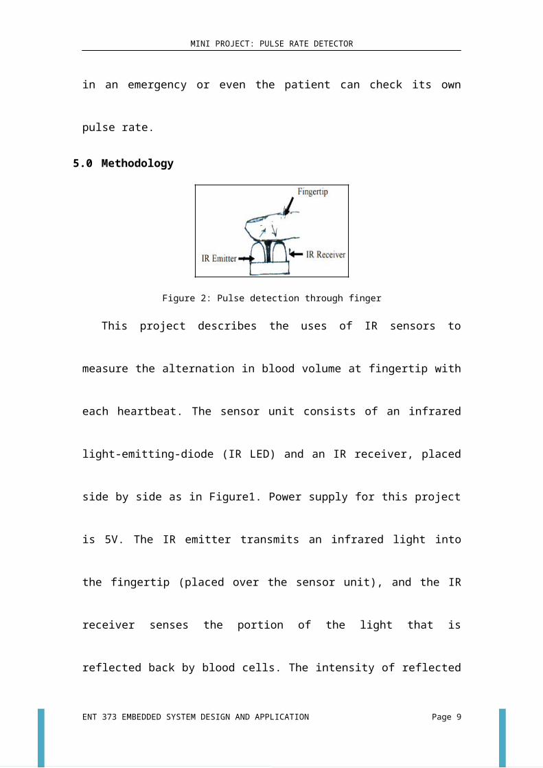
Figure 2: Pulse detection through finger
This project describes the uses of IR sensors to measure the alternation in blood
volume at fingertip with each heartbeat. The sensor unit consists of an infrared light-
emitting-diode (IR LED) and an IR receiver, placed side by side as in Figure1. Power
supply for this project is 5V. The IR emitter transmits an infrared light into the
fingertip (placed over the sensor unit), and the IR receiver senses the portion of the
light that is reflected back by blood cells. The intensity of reflected light depends
upon the blood volume inside the fingertip. So, each heartbeat slightly alters the
amount of reflected infrared light that can be detected by the IR receiver. With a
proper signal conditioning, this little change in the amplitude of the reflected light can
be converted into a pulse. The rate of heart pulses are shown at the output of the
Operational Amplifier. The number of blinking of the red L.E.D indicates the heart
beat of the person.
An analog input from the pulse rate detector circuit is then connected to the
PIC18F4580 as an analog input. The PIC will detect the signal and then convert the
signal into digital form. The timer in the PIC will start when the digital signal reaches
ENT 373 EMBEDDED SYSTEM DESIGN AND APPLICATION Page 4
MINI PROJECT: PULSE RATE DETECTOR
the threshold that we had set previously for one oscillation then the timer will stop.
Then the time for one oscillation is taken and it is converted into frequency. The value
of frequency is multiplied by 60 in order to get the value for beats per minute. At the
end, the result will be shown through LCD display.
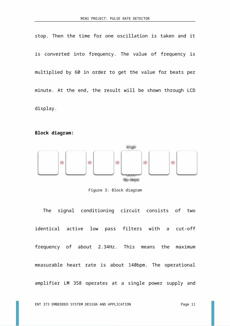
Block diagram:
Figure 3: Block diagram
The signal conditioning circuit consists of two identical active low pass filters
with a cut-off frequency of about 2.34Hz. This means the maximum measurable
heart rate is about 140bpm. The operational amplifier LM 358 operates at a single
power supply and provides rail-to-rail output swing. The filtering is necessary to
block any higher frequency noises present in the signal.
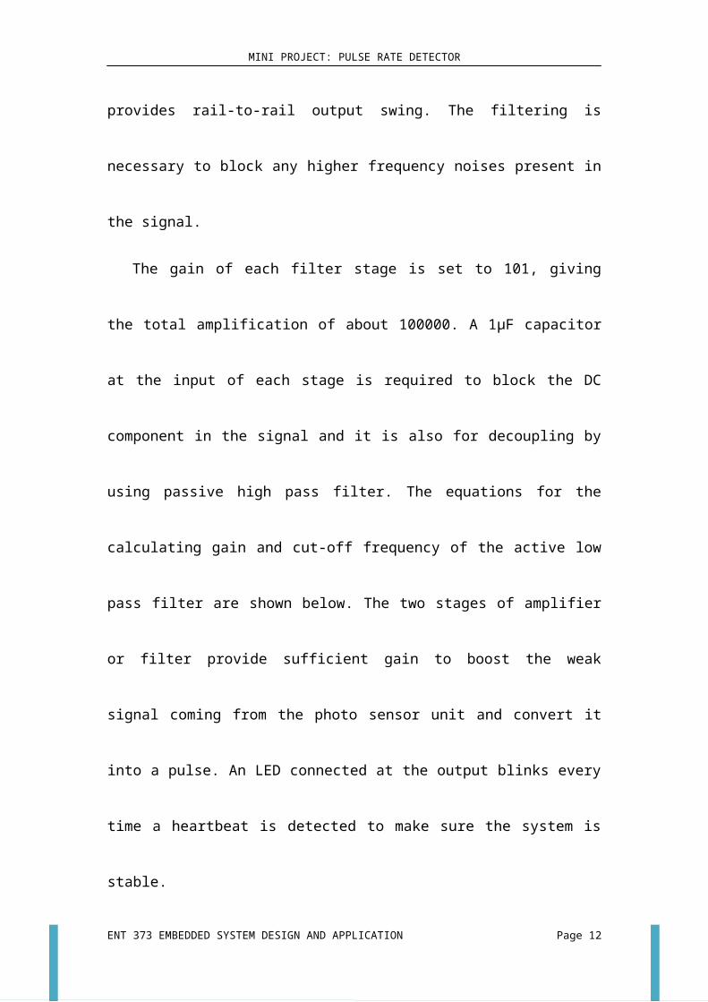
The gain of each filter stage is set to 101, giving the total amplification of about
100000. A 1µF capacitor at the input of each stage is required to block the DC
component in the signal and it is also for decoupling by using passive high pass filter.
The equations for the calculating gain and cut-off frequency of the active low pass
filter are shown below. The two stages of amplifier or filter provide sufficient gain to
boost the weak signal coming from the photo sensor unit and convert it into a pulse.
An LED connected at the output blinks every time a heartbeat is detected to make
sure the system is stable.
Cut off frequency= 12π R fC f
¿ 12π (68kΩ )(1μF )
ENT 373 EMBEDDED SYSTEM DESIGN AND APPLICATION Page 5
5V Infrared emitter
Infrared receiver
High gain,active low pass filter with Op-Amps
PIC18F4580 Display on LCD

MINI PROJECT: PULSE RATE DETECTOR
¿2.34Hz
Gainof eachstage=1+( R f
R7)
¿1+( 680 k6.8 k )
¿101
Total gain=101 x 101
¿10201
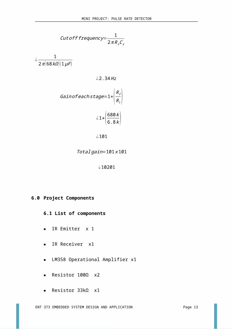
6.0 Project Components
6.1 List of components
IR Emitter x 1
IR Receiver x1
LM358 Operational Amplifier x1
Resistor 100Ω x2
Resistor 33kΩ x1
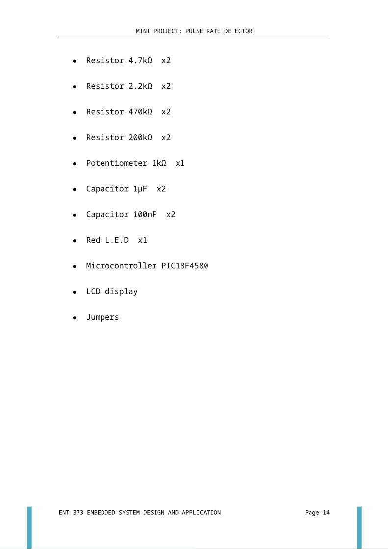
Resistor 4.7kΩ x2
Resistor 2.2kΩ x2
Resistor 470kΩ x2
Resistor 200kΩ x2
Potentiometer 1kΩ x1
Capacitor 1µF x2
Capacitor 100nF x2
Red L.E.D x1
Microcontroller PIC18F4580
LCD display
Jumpers
ENT 373 EMBEDDED SYSTEM DESIGN AND APPLICATION Page 6
MINI PROJECT: PULSE RATE DETECTOR
6.2 Usage of components
6.2.1 Resistor
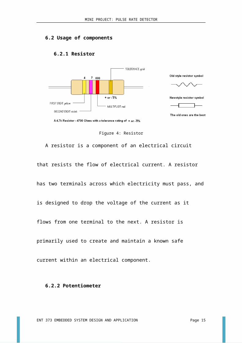
Figure 4: Resistor
A resistor is a component of an electrical circuit that resists the flow of electrical
current. A resistor has two terminals across which electricity must pass, and is
designed to drop the voltage of the current as it flows from one terminal to the next. A
resistor is primarily used to create and maintain a known safe current within an
electrical component.
6.2.2 Potentiometer
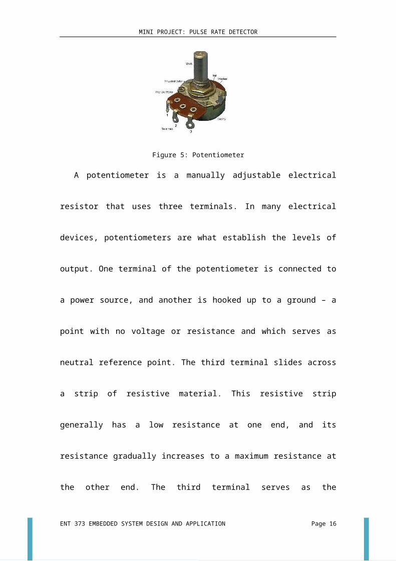
Figure 5: Potentiometer
A potentiometer is a manually adjustable electrical resistor that uses three
terminals. In many electrical devices, potentiometers are what establish the levels of
ENT 373 EMBEDDED SYSTEM DESIGN AND APPLICATION Page 7
MINI PROJECT: PULSE RATE DETECTOR
output. One terminal of the potentiometer is connected to a power source, and another
is hooked up to a ground – a point with no voltage or resistance and which serves as
neutral reference point. The third terminal slides across a strip of resistive material.
This resistive strip generally has a low resistance at one end, and its resistance
gradually increases to a maximum resistance at the other end. The third terminal
serves as the connection between the power source and ground, and it is usually
operated by the user through the use of a knob or lever.
6.2.3 IR Emitter and IR Receiver
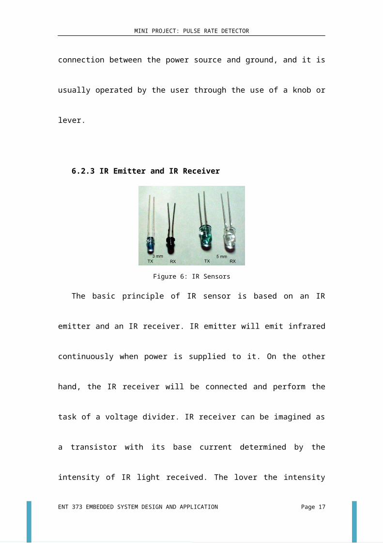
Figure 6: IR Sensors
The basic principle of IR sensor is based on an IR emitter and an IR receiver. IR
emitter will emit infrared continuously when power is supplied to it. On the other
hand, the IR receiver will be connected and perform the task of a voltage divider. IR
receiver can be imagined as a transistor with its base current determined by the
intensity of IR light received. The lover the intensity of IR light cause higher
resistance between collector-emitter terminals of transistor, and limiting current from
collector to emitter.
This change of resistance will further change the voltage at the output of voltage
divider. In other words, the greater the intensity of IR light hitting IR receiver, the
lower the resistance of IR receiver and hence the output voltage of voltage divider
will decreased. Usually the IR emitter and IR receiver will be mounted side by side,
pointing to a reflective surface. The further distance away between emitter and
receiver decrease the amount of infrared light hitting the receiver if the distance
between the sensor and a reflective surface is fixed.
ENT 373 EMBEDDED SYSTEM DESIGN AND APPLICATION Page 8
MINI PROJECT: PULSE RATE DETECTOR
6.2.3 Capacitor
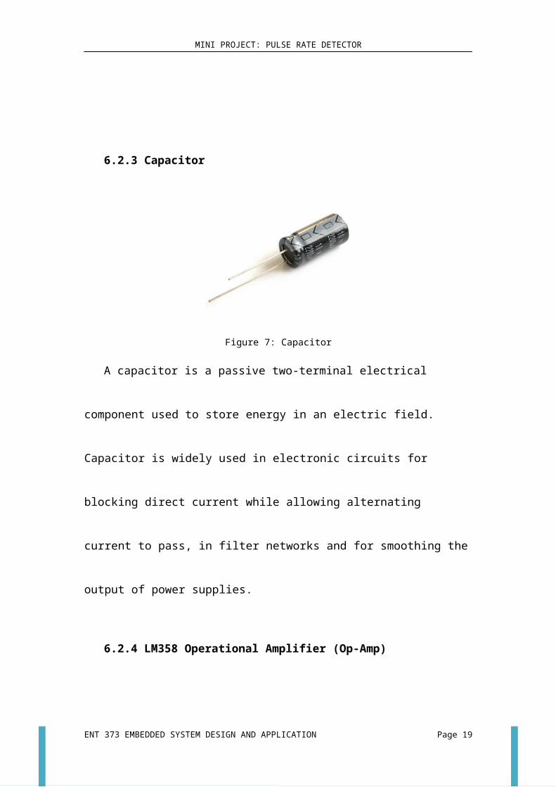
Figure 7: Capacitor
A capacitor is a passive two-terminal electrical component used to store energy in
an electric field. Capacitor is widely used in electronic circuits for blocking direct
current while allowing alternating current to pass, in filter networks and for
smoothing the output of power supplies.
6.2.4 LM358 Operational Amplifier (Op-Amp)
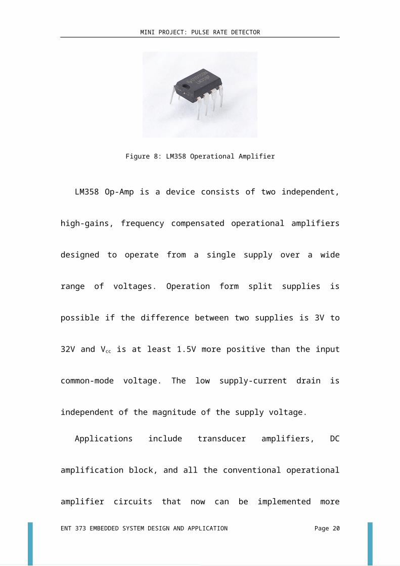
Figure 8: LM358 Operational Amplifier
LM358 Op-Amp is a device consists of two independent, high-gains, frequency
compensated operational amplifiers designed to operate from a single supply over a
wide range of voltages. Operation form split supplies is possible if the difference
ENT 373 EMBEDDED SYSTEM DESIGN AND APPLICATION Page 9
MINI PROJECT: PULSE RATE DETECTOR
between two supplies is 3V to 32V and Vcc is at least 1.5V more positive than the
input common-mode voltage. The low supply-current drain is independent of the
magnitude of the supply voltage.
Applications include transducer amplifiers, DC amplification block, and all the
conventional operational amplifier circuits that now can be implemented more easily
in single-supply-voltage systems.
6.2.4.1 Advantages of LM358 Op-Amp
- Two internally compensated op amps
- Eliminates need for dual supplies
-Allows direct sensing near GND and VOUT also goes to GND
- Compatible with all forms of logic
- Power drain suitable for battery operation.
ENT 373 EMBEDDED SYSTEM DESIGN AND APPLICATION Page 10
MINI PROJECT: PULSE RATE DETECTOR
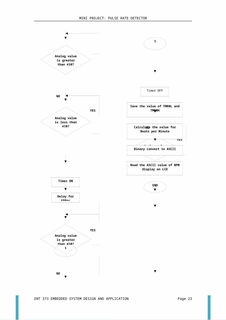
7.0 Flow chart
Circuit Diagram
ENT 373 EMBEDDED SYSTEM DESIGN AND APPLICATION Page 11
START
LCD SETUP
Timer ON
Timer OFF
Analog value is greater than
410?
Analog value is less than 410?
YES
Delay for 600ms
Timer ON
NO
Analog value is greater than
410?
NO
YES
YES
1
1
Analog value is less than 400?
NO
Timer OFF
YESCalculate the value for Beats per
Minute
NO
Read the ASCII value of BPM display on LCD
Binary convert to ASCII
Save the value of TMR0L and TMR0H
END
MINI PROJECT: PULSE RATE DETECTOR
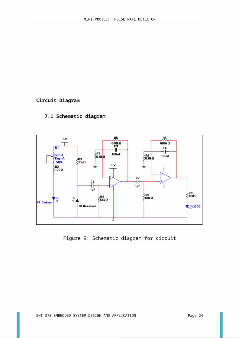
7.1 Schematic diagram
Figure 9: Schematic diagram for circuit
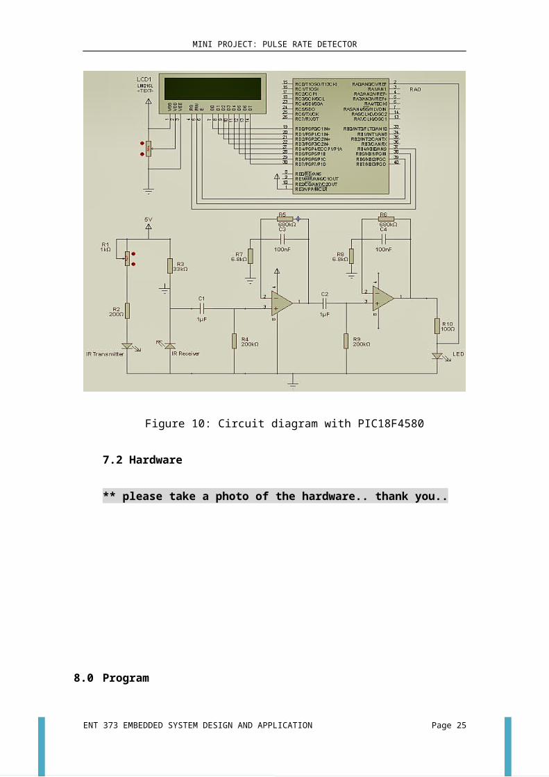
Figure 10: Circuit diagram with PIC18F4580
ENT 373 EMBEDDED SYSTEM DESIGN AND APPLICATION Page 12
MINI PROJECT: PULSE RATE DETECTOR
7.2 Hardware
** please take a photo of the hardware.. thank you..
8.0 Program
Please refer to Appendix A
ENT 373 EMBEDDED SYSTEM DESIGN AND APPLICATION Page 13
MINI PROJECT: PULSE RATE DETECTOR
9.0 Results
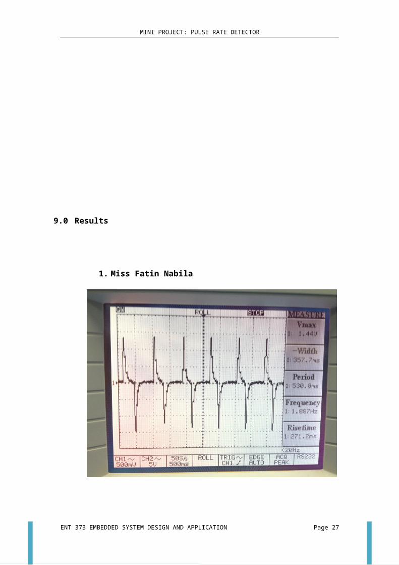
1. Miss Fatin Nabila
Theoretically calculation based on the pulse rate frequency in oscilloscope
output
Pulse rate frequency is 1.887 Hz.
Beat per minute=1.887Hz×60 s
¿113.22bpm@113bpm
Detected pulse rate in 15 seconds is 28 beats (Red LED blinks for 28 times)
The reading from LCD is in the range of 95 bpm to 118 bpm.
ENT 373 EMBEDDED SYSTEM DESIGN AND APPLICATION Page 14
Beat per minute=28x 4¿112bpm
MINI PROJECT: PULSE RATE DETECTOR
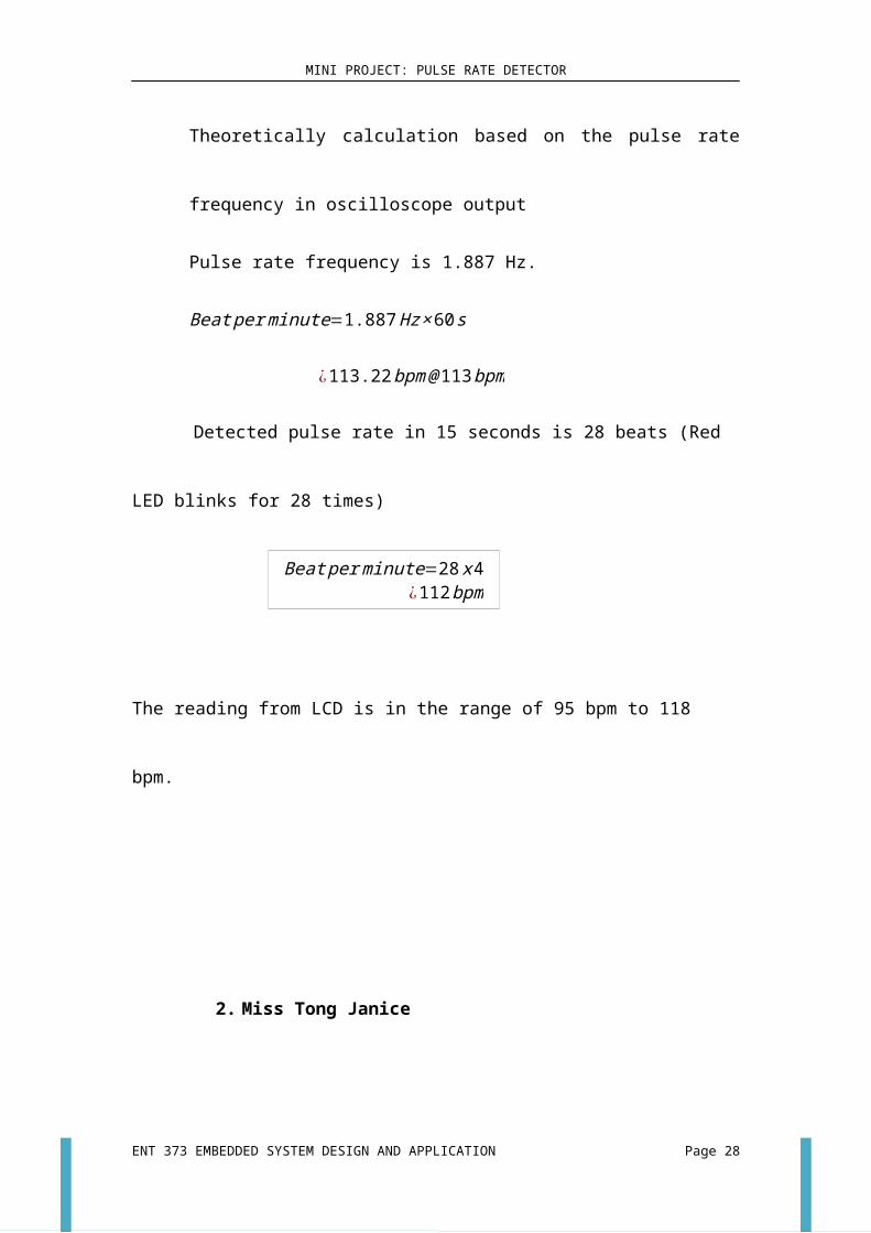
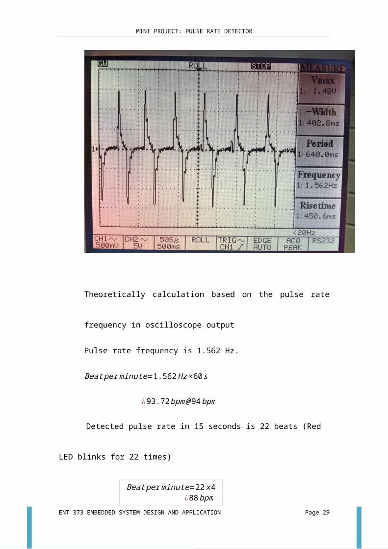
2. Miss Tong Janice
Theoretically calculation based on the pulse rate frequency in oscilloscope
output
Pulse rate frequency is 1.562 Hz.
Beat per minute=1.562Hz×60 s
¿93.72bpm@94bpm
Detected pulse rate in 15 seconds is 22 beats (Red LED blinks for 22 times)
The reading from LCD is in the range of 73 bpm to 118 bpm.
ENT 373 EMBEDDED SYSTEM DESIGN AND APPLICATION Page 15
Beat per minute=22x 4¿88bpm
MINI PROJECT: PULSE RATE DETECTOR
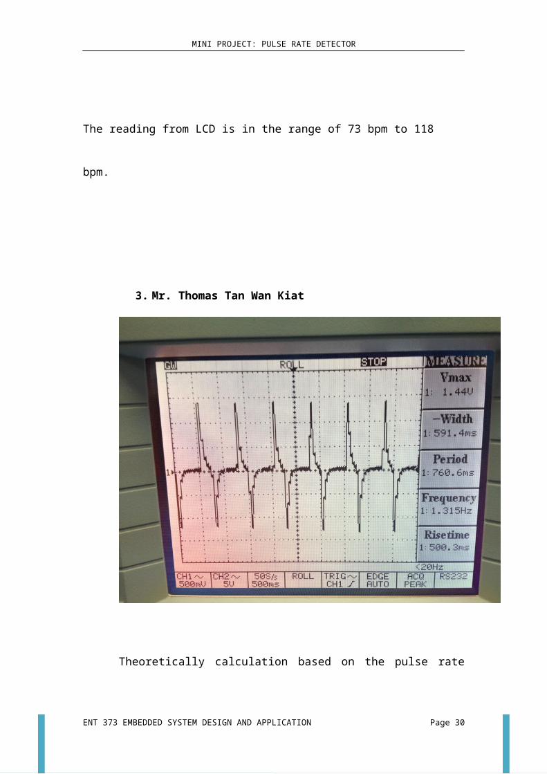
3. Mr. Thomas Tan Wan Kiat
Theoretically calculation based on the pulse rate frequency in oscilloscope
output
Pulse rate frequency is 1.315 Hz.
Beat per minute=1.315Hz×60 s
¿78.9bpm@79bpm
Detected pulse rate in 15 seconds is 19 beats (Red LED blinks for 19 times)
The reading from LCD is in the range of 73 bpm to 97 bpm.
ENT 373 EMBEDDED SYSTEM DESIGN AND APPLICATION Page 16
Beat per minute=19x 4¿76bpm
MINI PROJECT: PULSE RATE DETECTOR
10.0 Discussion
Our mini project, pulse detector has been successfully developed. However,
there are a few limitations of this project that we think it can still be improved in the
future.
First of all, we have discovered that the reading voltage from the IR sensor is
very small. Therefore, we designed a circuit which has 2 Operational Amplifiers to
magnify the reading. Besides that, when we test using oscilloscope, we found that
there are a lot of noise in the screen of the oscilloscope. In order to get rid of the
noise, we add in RC filter to reduce the noise of the oscilloscope reading. The main
reason we use the oscilloscope in our mini project is to test and study the signal from
output and to confirm our circuit diagram is functioning correctly.
10.1 Code section
This part of the program is used to take time for one oscillation. The timer starts
from the point of threshold that we had set which is 410 and end also at 410 in
order to complete and oscillation.
Functions:
T0CONbits.TMR0ON=0;
TMR0H=0;
TMR0L=0;
while(analogRead(RA0)>410);// low
while(analogRead(RA0)<410);//peak
T0CONbits.TMR0ON=1;
delay(600);
while(analogRead(RA0)>415);//peak
while(analogRead(RA0)<415);//low
T0CONbits.TMR0ON=0;
TL=TMR0L;
TH=TMR0H;
ENT 373 EMBEDDED SYSTEM DESIGN AND APPLICATION Page 17

MINI PROJECT: PULSE RATE DETECTOR
pulse=TH;
pulse= pulse <<8;
pulse= pulse | TL;
From the function “unsigned int analogRead(unsigned char PIN)”, we have to
separated into several parts in order to explain what is going on in this function. We
will keep looping this function in order to get the value of analog input convert to
digital input.
switch(PIN)
{
case 2:
ch=0;
break;
case 3:
ch=1;
break;
case 4:
ch=2;
break;
case 5:
ch=3;
break;
case 7:
ch=4;
break;
case 8:
ch=5;
break;
case 9:
ch=6;
break;
case 10:
ENT 373 EMBEDDED SYSTEM DESIGN AND APPLICATION Page 18
MINI PROJECT: PULSE RATE DETECTOR
ch=7;
break;
case 34:
ch=8;
break;
case 37:
ch=9;
break;
case 33:
ch=10;
break;
default:
break;
}
This part in the function is used to select the channel to be us in PIC.
ADCON0=0x00;
ADCON1=0x0E;
ADCON2=0xBF;
CMCON=0x07;
ADCON0bits.ADON=1; //Turn on A/D module (ADCON0)
//Start conversion
ADCON0bits.GO=1; //Set GO/DONE bit (ADCON0 register)
while(ADCON0bits.GO==1); //Polling for the GO/DONE bit to be cleared
This part in the function is called to setup the ADC module.
Only channel 0 of ADC is used. Configured as 10-bit, right justified. Comparators Off
//Read A/D Result registers (ADRESH:ADRESL)
ADC_Result=ADRESH;
ADC_Result=ADC_Result << 8;
ADC_Result=ADC_Result | ADRESL;
//return ADC_Result
ENT 373 EMBEDDED SYSTEM DESIGN AND APPLICATION Page 19
MINI PROJECT: PULSE RATE DETECTOR
return ADC_Result;
This part in the function is used to commence ADC conversion, then returns a value
variable INTEGER. In this, it is demonstrated how to merge two high-low 8-bit
registers into one 16-bit register.
num1=num1*512;
The actual time for tick when a prescaler of 256 adding to the timer is
14×20MHz=5000000MHz
1256
×5000000MHz=19531.25Hz due to prescaler 1:256
T= 119531.25
=5.12×10⁻⁵ s
This can be done by using Timer0’s TOPS bits in the PIC. Unfortunately, in this
program we insert the time for one tick manually easier for us to read the flow of the
program. We use 512 instead of using 5.12×10⁻⁵ is due to we want to eliminate the
decimal make it to integer better for our calculation.
bpm1=600000;
bpm=bpm1/a;
In the program, for calculating the beat per minutes, we use 600000 instead of using
60 in order to eliminate the decimal value so that it is easier for us to convert the value
to ASCII for the LCD to read.
From this mini project, we found that the value or the results which shown in the
LCD is not very stable. After we studied, we suggested that this mini project can still
be upgraded or to be more accurate by using GUI, LabView with the help of
microcontroller as a DAQ. This might get a more accurate value and all the results
can show in wave form and digital form as well as all the calculations.
11.0 Conclusion
In conclusion, our mini project is about designing and developing a low cost
ENT 373 EMBEDDED SYSTEM DESIGN AND APPLICATION Page 20
MINI PROJECT: PULSE RATE DETECTOR
pulse detector to detect pulse rate in an easier and simpler way. Overall, this project
has achieved our objectives and it has been beginning by constructing circuit until it
testing step by step to achieve the functionality we need for this project. We noticed
that is a good way of learning to have this mini project because we able to learn more
about programming and the other application which we are able and unable to learn in
class. Our mini project, pulse detector has been successfully developed and tested.
12.0 Acknowledgement
First of all, the special thank goes to our helpful lecturer, En. Nasir, and our
Vocational Training Officer (PLV), En Ismail. They gave us this opportunity by
giving us this mini project. They gave us fully support by helping us in the
progression and smoothness of the mini project. The co-operation is much indeed
appreciated.
Secondly, a million thanks to our group members: Tong Janice, Thomas Tan Wan
Kiat and Fatin Nabila. Each of them contributed their hard time and energy during
this few weeks when completing this mini project. All hard work would be nothing
without the enthusiasm, imagination and co-operation from all of them.
Last but not least, we would like to thank all my course-mates and friends for
kindly helping us when we seek for help or facing problem when doing this mini
project.
13.0 Reference
1. Design and Development of a Heart Rate Measuring Device Using Fingertip, M.M.A. Hashem, Rushdi Shams, Md. Abdul Kader, Md.Abu Sayed, Department of Computer Science and Engineering, ICCCE2010,11-13 May 2010, KL, Malaysia.
2. Dogan Ibrahim and Kadri Buruncuk “Heart Rate Measurement from The
Finger Using A Low-Cost Microcontroller”.
3. Muhammad Ali Mazidi, Rolin and Danny (2008) , PIC Microcontroller and
Embedded Systems, Pearson International Edition.
ENT 373 EMBEDDED SYSTEM DESIGN AND APPLICATION Page 21

MINI PROJECT: PULSE RATE DETECTOR
4. Nilsson and Riedel, Electric Circuits, Ninth Edition, Pearson International
Edition.
5. Pulse. [Retrieved on 10 November 2012]
http://www.nlm.nih.gov/medlineplus/ency/article/003399.htm
6. Rajendra Bhatt (2011, January 18) “ Heart Rate Measurement From
Fingertip” [Retrieved on 8 November 2012]
http://embedded-lab.com/blog/?p=1671
Appendix A
C-Program for PIC 18F4580
#include <p18f4580.h>
#include <delays.h>
// PIC18F4580 Configuration Bit Settings
// CONFIG1H
#pragma config OSC = HS // Oscillator Selection bits (HS oscillator)
ENT 373 EMBEDDED SYSTEM DESIGN AND APPLICATION Page 22
MINI PROJECT: PULSE RATE DETECTOR
#pragma config FCMEN = OFF // Fail-Safe Clock Monitor Enable bit (Fail-Safe Clock Monitor disabled)
#pragma config IESO = OFF // Internal/External Oscillator Switchover bit (Oscillator Switchover mode disabled)
// CONFIG2L
#pragma config PWRT = OFF // Power-up Timer Enable bit (PWRT disabled)
#pragma config BOREN = OFF // Brown-out Reset Enable bits (Brown-out Reset disabled in hardware and software)
#pragma config BORV = 0 // Brown-out Reset Voltage bits (VBOR set to 4.6V)
// CONFIG2H
#pragma config WDT = OFF // Watchdog Timer Enable bit (WDT disabled (control is placed on the SWDTEN bit))
#pragma config WDTPS = 32768 // Watchdog Timer Postscale Select bits (1:32768)
// CONFIG3H
#pragma config PBADEN = OFF // PORTB A/D Enable bit (PORTB<4:0> pins are configured as digital I/O on Reset)
#pragma config LPT1OSC = OFF // Low-Power Timer 1 Oscillator Enable bit (Timer1 configured for higher power
operation)
#pragma config MCLRE = ON // MCLR Pin Enable bit (MCLR pin enabled; RE3 input pin disabled)
// CONFIG4L
#pragma config STVREN = OFF // Stack Full/Underflow Reset Enable bit (Stack full/underflow will not cause Reset)
#pragma config LVP = OFF // Single-Supply ICSP Enable bit (Single-Supply ICSP disabled)
#pragma config BBSIZ = 1024 // Boot Block Size Select bit (1K words (2K bytes) boot block)
#pragma config XINST = OFF // Extended Instruction Set Enable bit (Instruction set extension and Indexed Addressing
// mode disabled (Legacy mode))
// CONFIG5L
#pragma config CP0 = OFF // Code Protection bit (Block 0 (000800-001FFFh) not code-protected)
#pragma config CP1 = OFF // Code Protection bit (Block 1 (002000-003FFFh) not code-protected)
#pragma config CP2 = OFF // Code Protection bit (Block 2 (004000-005FFFh) not code-protected)
#pragma config CP3 = OFF // Code Protection bit (Block 3 (006000-007FFFh) not code-protected)
// CONFIG5H
#pragma config CPB = OFF // Boot Block Code Protection bit (Boot block (000000-0007FFh) not code-protected)
#pragma config CPD = OFF // Data EEPROM Code Protection bit (Data EEPROM not code-protected)
// CONFIG6L
#pragma config WRT0 = OFF // Write Protection bit (Block 0 (000800-001FFFh) not write-protected)
#pragma config WRT1 = OFF // Write Protection bit (Block 1 (002000-003FFFh) not write-protected)
#pragma config WRT2 = OFF // Write Protection bit (Block 2 (004000-005FFFh) not write-protected)
#pragma config WRT3 = OFF // Write Protection bit (Block 3 (006000-007FFFh) not write-protected)
// CONFIG6H
#pragma config WRTC = OFF // Configuration Register Write Protection bit (Configuration registers (300000-
3000FFh) not write-protected)
ENT 373 EMBEDDED SYSTEM DESIGN AND APPLICATION Page 23
MINI PROJECT: PULSE RATE DETECTOR
#pragma config WRTB = OFF // Boot Block Write Protection bit (Boot block (000000-0007FFh) not write-protected)
#pragma config WRTD = OFF // Data EEPROM Write Protection bit (Data EEPROM not write-protected)
// CONFIG7L
#pragma config EBTR0 = OFF // Table Read Protection bit (Block 0 (000800-001FFFh) not protected from table reads
// executed in other blocks)
#pragma config EBTR1 = OFF // Table Read Protection bit (Block 1 (002000-003FFFh) not protected from table reads
// executed in other blocks)
#pragma config EBTR2 = OFF // Table Read Protection bit (Block 2 (004000-005FFFh) not protected from table reads
executed in other blocks)
#pragma config EBTR3 = OFF // Table Read Protection bit (Block 3 (006000-007FFFh) not protected from table reads
executed in other blocks)
// CONFIG7H
#pragma config EBTRB = OFF //Boot Block Table Read Protection bit (Boot block (000000-0007FFh) not protected
from
//table reads executed in other blocks)
#define RA0 2
void lcd_com(unsigned char y);
void lcd_dat(unsigned char y);
void lcd_setup(void);
void lcd_Clear(void);
void lcd_convert_Timer(unsigned int num);
unsigned int analogRead(unsigned char PIN );
void delay(unsigned long TIME);
void lcd_setCursor(unsigned char LINE, unsigned char COLUME);
void main(void)
{
unsigned int pulse;
unsigned int mean;
unsigned char i, TL,TH;
lcd_setup();
//timer on
T0CON=0x07;
T0CONbits.TMR0ON=1;
while(1)
{
T0CONbits.TMR0ON=0;
TMR0H=0;
TMR0L=0;
while(analogRead(RA0)>410);// low
ENT 373 EMBEDDED SYSTEM DESIGN AND APPLICATION Page 24
MINI PROJECT: PULSE RATE DETECTOR
while(analogRead(RA0)<410);//peak
T0CONbits.TMR0ON=1;
delay(600);
while(analogRead(RA0)>415);//peak
while(analogRead(RA0)<415);//low
T0CONbits.TMR0ON=0;
TL=TMR0L;
TH=TMR0H;
pulse=TH;
pulse= pulse <<8;
pulse= pulse | TL;
// mean
lcd_Clear();
lcd_convert_Timer(pulse);
}
}
void lcd_convert_Timer(unsigned int num)
{
unsigned char s1,s2,s3,s4;
unsigned int m1,m2;
unsigned char d1, d2, d3,d4,d5,d6,d7,d8;
unsigned short long num1,n1,n2,n3,n4,n5,n6,bpm,bpm1;
unsigned int a4,a3,a2,a1,a,T,T1,T2;
//VOLTAGE
// 5/(2^10)=4.88mV > 10bit ADC
// to avoid floating point we take 1 = 0.01mV
// So 4.88mV repersent as 488
//1024 * 488 = 499712
// also 4.99 v
num1=num;
num1=num1*512;
n1=num1/10;
d1=num1%10;//One
n2=n1/10;
d2=n1%10;//Ten
n3=n2/10;
d3=n2%10;//Hundred
n4=n3/10;
d4=n3%10;//Thousand
n5=n4/10;
d5=n4%10;//Ten thousand
ENT 373 EMBEDDED SYSTEM DESIGN AND APPLICATION Page 25

MINI PROJECT: PULSE RATE DETECTOR
n6=n5/10;
d6=n5%10;//Hundred thousand
d7=n6%10;//1b
d8=n6/10;//10 b
T=1000;
T1=100;
T2=10;
a1=d8*T;
a2=d7*T1;
a3=d6*T2;
a4=d5;
a=a1+a2+a3+a4;
//lcd_convert(a);
bpm1=600000;
bpm=bpm1/a;
//STEP
m1=bpm/10;
s1=bpm%10;//One
m2=m1/10;
s2=m1%10;//Ten
s3=m2%10;//Hundred
s4=m2/10;//Thousand
s1=s1+0x30;
s2=s2+0x30;
s3=s3+0x30;
s4=s4+0x30;
lcd_setCursor(1,1);
lcd_dat('H');
lcd_dat('E');
lcd_dat('A');
lcd_dat('R');
lcd_dat('T');
lcd_dat(' ');
lcd_dat('P');
lcd_dat('U');
lcd_dat('L');
lcd_dat('S');
lcd_dat('E');
ENT 373 EMBEDDED SYSTEM DESIGN AND APPLICATION Page 26
MINI PROJECT: PULSE RATE DETECTOR
lcd_setCursor(2,1);
lcd_dat(s4);
lcd_dat(s3);
lcd_dat(s2);
lcd_dat('.');
lcd_dat(s1);
lcd_dat(' ');
lcd_dat('b');
lcd_dat('p');
lcd_dat('m');
}
unsigned int analogRead(unsigned char PIN )
{
unsigned int ADC_Result;
unsigned char ch;
//Select channel
switch(PIN)
{
case 2:
ch=0;
break;
case 3:
ch=1;
break;
case 4:
ch=2;
break;
case 5:
ch=3;
break;
case 7:
ch=4;
break;
case 8:
ch=5;
ENT 373 EMBEDDED SYSTEM DESIGN AND APPLICATION Page 27
MINI PROJECT: PULSE RATE DETECTOR
break;
case 9:
ch=6;
break;
case 10:
ch=7;
break;
case 34:
ch=8;
break;
case 37:
ch=9;
break;
case 33:
ch=10;
break;
default:
break;
}
//Initial ADC Module
ADCON0=0x00;
ADCON1=0x0E;
ADCON2=0xBF;
CMCON=0x07;
ADCON0bits.ADON=1; //Turn on A/D module (ADCON0)
//Start conversion
ADCON0bits.GO=1; //Set GO/DONE bit (ADCON0 register)
while(ADCON0bits.GO==1); //Polling for the GO/DONE bit to be cleared
//Read A/D Result registers (ADRESH:ADRESL)
ADC_Result=ADRESH;
ADC_Result=ADC_Result << 8;
ADC_Result=ADC_Result | ADRESL;
//return ADC_Result
return ADC_Result;
}
ENT 373 EMBEDDED SYSTEM DESIGN AND APPLICATION Page 28
MINI PROJECT: PULSE RATE DETECTOR
void lcd_com(unsigned char y)
{
PORTD=y; //Send data to LCD (PORTD)
PORTBbits.RB4=0; //Clear RS pins (RB4)
PORTBbits.RB5=1; //Set EN pins (RB5)
Delay1KTCYx(10); //Waiting for Execution Cycle finish
PORTBbits.RB5=0; //Clear EN pins (RB5)
}
void lcd_dat(unsigned char y)
{
PORTD=y; //Send data to LCD (PORTD)
PORTBbits.RB4=1; //Clear RS pins (RB4)
PORTBbits.RB5=1; //Set EN pins (RB5)
Delay1KTCYx(10); //Waiting for Execution Cycle finish
PORTBbits.RB5=0; //Clear EN pins (RB5)
}
void lcd_setup(void)
{
//Setup LCD
TRISD=0; //Configure LCD data pins as Output (PORTD)
TRISBbits.TRISB4=0; //Configure RS pins as Output(RB4)
TRISBbits.TRISB5=0; //Configure EN pins as Output(RB5)
lcd_com(0x01); //Display clear (0x01)
lcd_com(0x38); //Function set (8bit,2-line display,5 x 8 dot)
lcd_com(0x0C); //Display on/off control (Display on,Cursor off,Blinking off)
lcd_com(0x06); //Entry mode set (Increment by 1,No shift)
lcd_com(0x80); //Set up Cursor location
}
void lcd_Clear(void)
{
lcd_com(0x01);
}
void lcd_setCursor(unsigned char LINE, unsigned char COLUME)
{
COLUME=COLUME-1;
switch(LINE)
{
case 1:
ENT 373 EMBEDDED SYSTEM DESIGN AND APPLICATION Page 29
MINI PROJECT: PULSE RATE DETECTOR
lcd_com(0x80+COLUME);
break;
case 2:
lcd_com(0xC0+COLUME);
break;
default:
break;
}
}
void delay(unsigned long TIME)
{
do
{
Delay1KTCYx(5);// 1ms for 20 MHz
TIME=TIME-1;
}
while(TIME>0);
}
Appendix B: Data Sheets of LM358
ENT 373 EMBEDDED SYSTEM DESIGN AND APPLICATION Page 30
MINI PROJECT: PULSE RATE DETECTOR
ENT 373 EMBEDDED SYSTEM DESIGN AND APPLICATION Page 31