Embed Size (px)
Citation preview
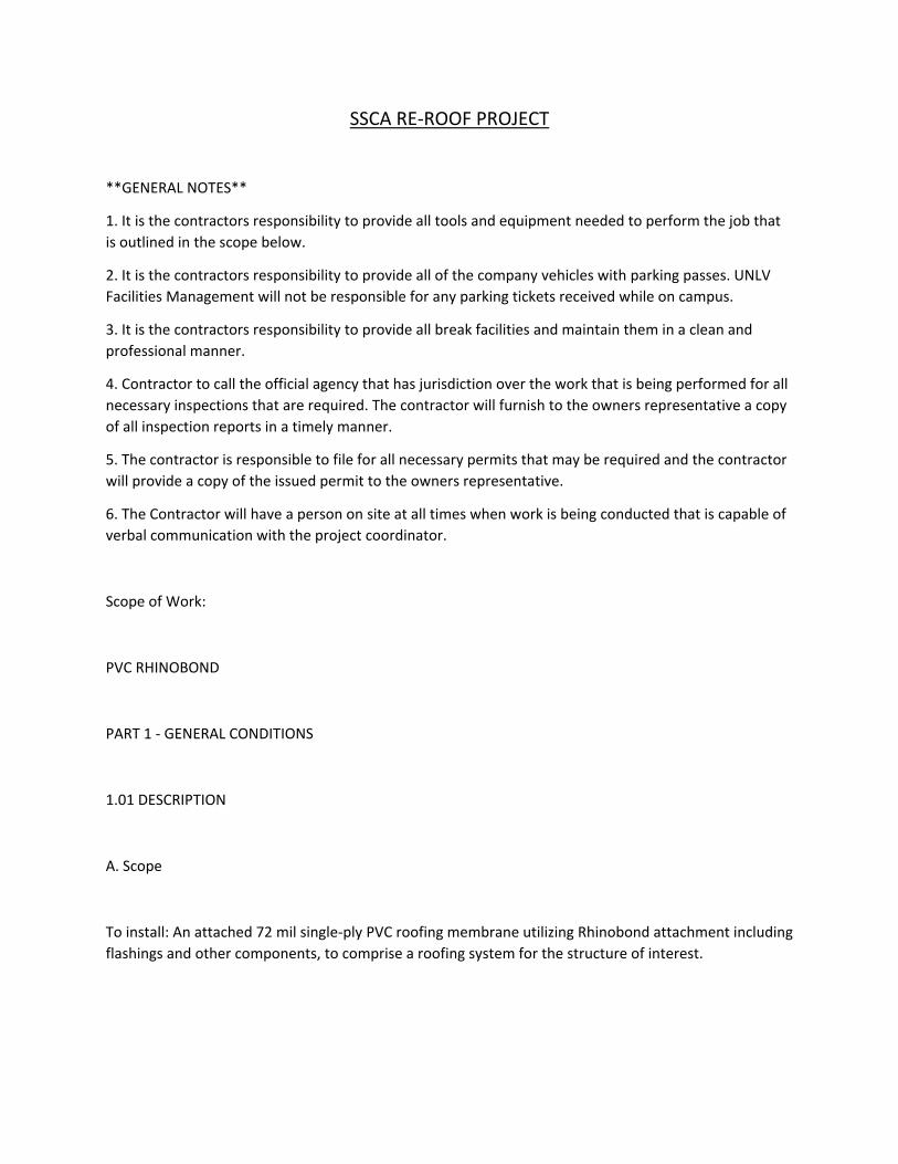
SSCA RE‐ROOF PROJECT
**GENERAL NOTES**
1. It is the contractors responsibility to provide all tools and equipment needed to perform the job that
is outlined in the scope below.
2. It is the contractors responsibility to provide all of the company vehicles with parking passes. UNLV
Facilities Management will not be responsible for any parking tickets received while on campus.
3. It is the contractors responsibility to provide all break facilities and maintain them in a clean and
professional manner.
4. Contractor to call the official agency that has jurisdiction over the work that is being performed for all
necessary inspections that are required. The contractor will furnish to the owners representative a copy
of all inspection reports in a timely manner.
5. The contractor is responsible to file for all necessary permits that may be required and the contractor
will provide a copy of the issued permit to the owners representative.
6. The Contractor will have a person on site at all times when work is being conducted that is capable of
verbal communication with the project coordinator.
Scope of Work:
PVC RHINOBOND
PART 1 ‐ GENERAL CONDITIONS
1.01 DESCRIPTION
A. Scope
To install: An attached 72 mil single‐ply PVC roofing membrane utilizing Rhinobond attachment including
flashings and other components, to comprise a roofing system for the structure of interest.
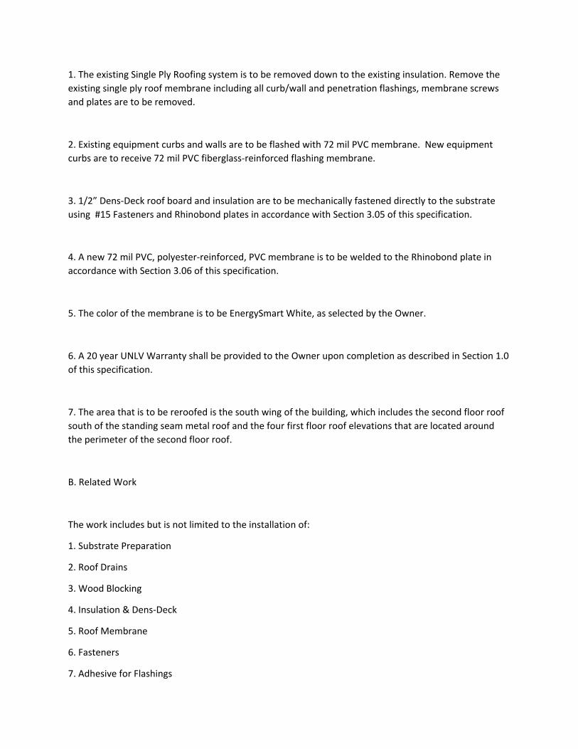
1. The existing Single Ply Roofing system is to be removed down to the existing insulation. Remove the
existing single ply roof membrane including all curb/wall and penetration flashings, membrane screws
and plates are to be removed.
2. Existing equipment curbs and walls are to be flashed with 72 mil PVC membrane. New equipment
curbs are to receive 72 mil PVC fiberglass‐reinforced flashing membrane.
3. 1/2” Dens‐Deck roof board and insulation are to be mechanically fastened directly to the substrate
using #15 Fasteners and Rhinobond plates in accordance with Section 3.05 of this specification.
4. A new 72 mil PVC, polyester‐reinforced, PVC membrane is to be welded to the Rhinobond plate in
accordance with Section 3.06 of this specification.
5. The color of the membrane is to be EnergySmart White, as selected by the Owner.
6. A 20 year UNLV Warranty shall be provided to the Owner upon completion as described in Section 1.0
of this specification.
7. The area that is to be reroofed is the south wing of the building, which includes the second floor roof
south of the standing seam metal roof and the four first floor roof elevations that are located around
the perimeter of the second floor roof.
B. Related Work
The work includes but is not limited to the installation of:
1. Substrate Preparation
2. Roof Drains
3. Wood Blocking
4. Insulation & Dens‐Deck
5. Roof Membrane
6. Fasteners
7. Adhesive for Flashings
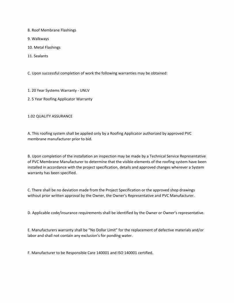
8. Roof Membrane Flashings
9. Walkways
10. Metal Flashings
11. Sealants
C. Upon successful completion of work the following warranties may be obtained:
1. 20 Year Systems Warranty ‐ UNLV
2. 5 Year Roofing Applicator Warranty
1.02 QUALITY ASSURANCE
A. This roofing system shall be applied only by a Roofing Applicator authorized by approved PVC
membrane manufacturer prior to bid.
B. Upon completion of the installation an inspection may be made by a Technical Service Representative
of PVC Membrane Manufacturer to determine that the visible elements of the roofing system have been
installed in accordance with the project specification, details and approved changes wherever a System
warranty has been specified.
C. There shall be no deviation made from the Project Specification or the approved shop drawings
without prior written approval by the Owner, the Owner's Representative and PVC Manufacturer.
D. Applicable code/insurance requirements shall be identified by the Owner or Owner’s representative.
E. Manufacturers warranty shall be “No Dollar Limit” for the replacement of defective materials and/or
labor and shall not contain any exclusion’s for ponding water.
F. Manufacturer to be Responsible Care 140001 and ISO 140001 certified.
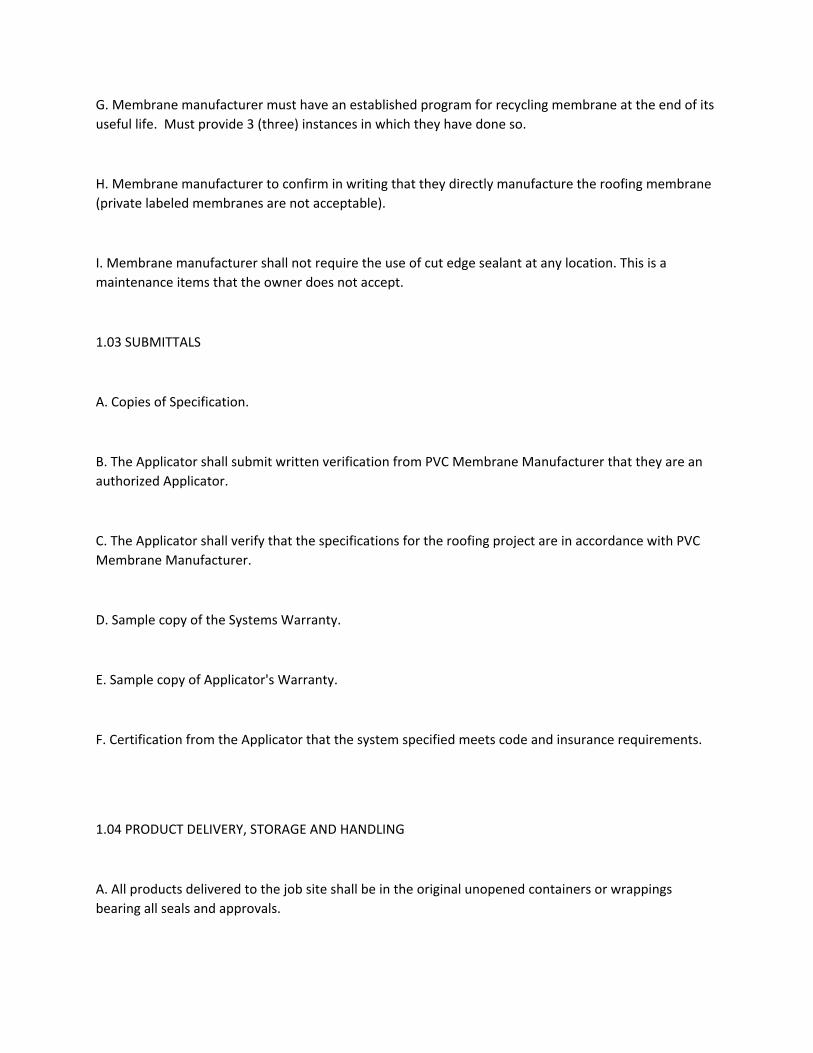
G. Membrane manufacturer must have an established program for recycling membrane at the end of its
useful life. Must provide 3 (three) instances in which they have done so.
H. Membrane manufacturer to confirm in writing that they directly manufacture the roofing membrane
(private labeled membranes are not acceptable).
I. Membrane manufacturer shall not require the use of cut edge sealant at any location. This is a
maintenance items that the owner does not accept.
1.03 SUBMITTALS
A. Copies of Specification.
B. The Applicator shall submit written verification from PVC Membrane Manufacturer that they are an
authorized Applicator.
C. The Applicator shall verify that the specifications for the roofing project are in accordance with PVC
Membrane Manufacturer.
D. Sample copy of the Systems Warranty.
E. Sample copy of Applicator's Warranty.
F. Certification from the Applicator that the system specified meets code and insurance requirements.
1.04 PRODUCT DELIVERY, STORAGE AND HANDLING
A. All products delivered to the job site shall be in the original unopened containers or wrappings
bearing all seals and approvals.
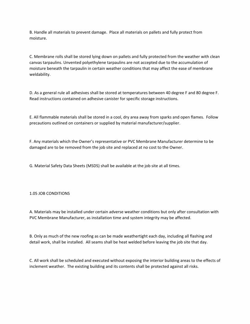
B. Handle all materials to prevent damage. Place all materials on pallets and fully protect from
moisture.
C. Membrane rolls shall be stored lying down on pallets and fully protected from the weather with clean
canvas tarpaulins. Unvented polyethylene tarpaulins are not accepted due to the accumulation of
moisture beneath the tarpaulin in certain weather conditions that may affect the ease of membrane
weldability.
D. As a general rule all adhesives shall be stored at temperatures between 40 degree F and 80 degree F.
Read instructions contained on adhesive canister for specific storage instructions.
E. All flammable materials shall be stored in a cool, dry area away from sparks and open flames. Follow
precautions outlined on containers or supplied by material manufacturer/supplier.
F. Any materials which the Owner’s representative or PVC Membrane Manufacturer determine to be
damaged are to be removed from the job site and replaced at no cost to the Owner.
G. Material Safety Data Sheets (MSDS) shall be available at the job site at all times.
1.05 JOB CONDITIONS
A. Materials may be installed under certain adverse weather conditions but only after consultation with
PVC Membrane Manufacturer, as installation time and system integrity may be affected.
B. Only as much of the new roofing as can be made weathertight each day, including all flashing and
detail work, shall be installed. All seams shall be heat welded before leaving the job site that day.
C. All work shall be scheduled and executed without exposing the interior building areas to the effects of
inclement weather. The existing building and its contents shall be protected against all risks.
D. All surfaces to receive new insulation, Dens‐Deck, membrane or flashings shall be dry. Should surface
moisture occur, the Applicator shall provide the necessary equipment to dry the surface prior to
application.
E. All new and temporary construction, including equipment and accessories, shall be secured in such a
manner as to preclude wind blow‐off and subsequent roof or equipment damage.
F. Uninterrupted waterstops shall be installed at the end of each day's work and shall be completely
removed before proceeding with the next day's work. Waterstops shall not emit dangerous or unsafe
fumes and shall not remain in contact with the finished roof as the installation progresses.
Contaminated membrane shall be replaced at no cost to the Owner.
G. The Applicator is cautioned that certain PVC membranes are incompatible with asphalt, coal tar,
heavy oils, roofing cements, creosote and some preservative materials. Such materials shall not remain
in contact with PVC membranes. The Applicator shall consult PVC Membrane Manufacturer regarding
compatibility, precautions and recommendations.
H. Arrange work sequence to avoid use of newly constructed roofing as a walking surface or for
equipment movement and storage. Where such access is absolutely required, the Applicator shall
provide all necessary protection and barriers to segregate the work area and to prevent damage to
adjacent areas. A substantial protection layer consisting of plywood over felt or plywood over insulation
board shall be provided for all new and existing roof areas that receive rooftop traffic during
construction.
I. Prior to and during application, all dirt, debris and dust shall be removed from surfaces by vacuuming,
sweeping, blowing with compressed air or similar methods.
J. The Applicator shall follow all safety regulations as required by OSHA and any other applicable
authority having jurisdiction.
K. All new roofing waste material (i.e., scrap roof membrane, release paper, empty cans of adhesive)
shall be immediately removed from the site by the Applicator and properly transported to a legal
dumping area authorized to receive such material.
L. The Applicator shall take precautions that storage and application of materials and equipment does
not overload the roof deck or building structure.
M. Flammable adhesives and deck primers shall not be stored and not be used in the vicinity of open
flames, sparks and excessive heat.
N. All rooftop contamination that is anticipated or that is occurring shall be reported to PVC Membrane
Manufacturer to determine the corrective steps to be taken.
O. The Applicator shall verify that all roof drain lines are functioning correctly (not clogged or blocked)
before starting work. Applicator shall report any such blockages in writing (letter copy to PVC
Membrane Manufacturer) to the Owner's Representative for corrective action prior to the installation of
the PVC roof system.
P. Applicator shall immediately stop work if any unusual or concealed condition is discovered and shall
immediately notify Owner of such condition in writing.
Q. Site cleanup, including both interior and exterior building areas that have been affected by
construction, shall be completed to the Owner's satisfaction.
R. All landscaped areas damaged by construction activities shall be repaired at no cost to the Owner.
S. The Applicator shall conduct fastener pullout tests in accordance with the latest version of the
SPRI/ANSI Fastener Pullout Standard to help verify condition of the deck/substrate and to confirm
expected pullout values.
T. Precautions shall be taken when using flashing adhesives at or near rooftop vents or air intakes.
Adhesive odors could enter the building. Coordinate the operation of vents and air intakes in such a
manner as to avoid the intake of adhesive odor while ventilating the building. Keep lids on unused cans
at all times.
U. Protective wear shall be worn when using solvents or adhesives or as required by job conditions.
V. PVC membranes are slippery when wet or covered with snow, frost, or ice. Working on surfaces
under these conditions is hazardous. Appropriate safety measures must be implemented prior to
working on such surfaces. Always follow OSHA and other relevant fall protection standards when
working on roofs.
W. Aesthetics and Performance are equally important. The owner’s representative will require that all
flashings will be picture framed, details, and hand welding work shall be uniform and consistent
throughout the entire project. Giving the appearance that one individual performed all of the work. Any
sub‐standard work will be immediately corrected to the satisfaction of the Owner’s Representative.
1.06 WARRANTIES
A. 20‐year System Warranty (only products purchased from approved PVC Membrane Manufacturer are
covered under the UNLV System Warranty)
Upon successful completion of the work to the owners satisfaction and receipt of final payment, the 20‐
Year System Warranty (70‐mph wind speed) shall be issued.
B. Applicator/Roofing Contractor 5‐Year Warranty
Applicator shall supply Owner with a separate 5‐Year workmanship warranty. In the event any work
related to roofing, flashing, or metal is found to be within the Applicator warranty term, defective or
otherwise not in accordance with Contract Documents, the Applicator shall repair that defect at no cost
to Owner. Applicator's warranty obligation shall run directly to Owner and a copy shall be sent to the
manufacturer.
C. Owner Responsibility
Owner shall notify both the manufacturer and the Applicator of any leaks as they occur during the time
period when both warranties are in effect.
PART 2 ‐ PRODUCTS
2.01 GENERAL
A. All components of mechanically attached 72 mil single‐ply PVC roofing membrane utilizing
Rhinobond‐attached roof system shall be manufactured, supplied or accepted by the membrane
manufacturer.
B. Manufacturer to have a minimum of four years experience recycling their membranes at the end of
their service life back into new membrane products. Provide a minimum of five reference projects.
C. Condensation or moisture migration into the roof system must be controlled so that it does not
compromise the performance of components of the assembly. Moisture vapor tends to migrate from
warmer to cooler areas. Air/vapor retarders are used to inhibit or block the flow of warm moist air into
the roof system. To determine if an air/vapor barrier is necessary, a design professional with experience
with air handling and moisture control should be consulted.
D. Membrane shall be certified by the PVC manufacturer to be with three (3) mils of the specified
membrane thickness as stated in this section. ASTM minimum standards of +/_ 10% will not be
accepted.
E. Membrane shall have a minimum of thirty‐four (34) mils of waterproofing polymers above the
reinforcements as documented by a third party source.
2.02 MEMBRANE
A. A new 72 mil PVC S327, thermoplastic membrane with polyester reinforcement.
1. Approved Manufacturers; Sika Sarnafil, Durolast or pre‐approved Equal.
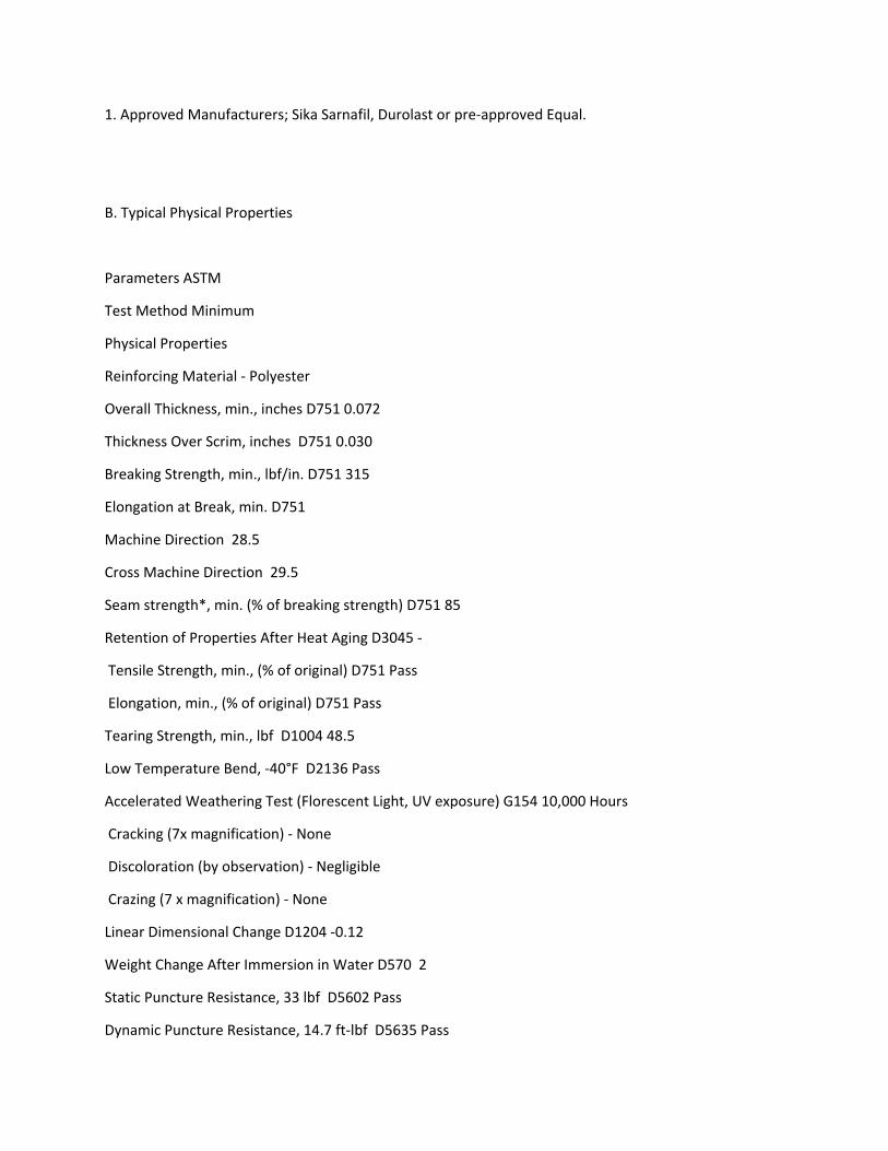
B. Typical Physical Properties
Parameters ASTM
Test Method Minimum
Physical Properties
Reinforcing Material ‐ Polyester
Overall Thickness, min., inches D751 0.072
Thickness Over Scrim, inches D751 0.030
Breaking Strength, min., lbf/in. D751 315
Elongation at Break, min. D751
Machine Direction 28.5
Cross Machine Direction 29.5
Seam strength*, min. (% of breaking strength) D751 85
Retention of Properties After Heat Aging D3045 ‐
Tensile Strength, min., (% of original) D751 Pass
Elongation, min., (% of original) D751 Pass
Tearing Strength, min., lbf D1004 48.5
Low Temperature Bend, ‐40°F D2136 Pass
Accelerated Weathering Test (Florescent Light, UV exposure) G154 10,000 Hours
Cracking (7x magnification) ‐ None
Discoloration (by observation) ‐ Negligible
Crazing (7 x magnification) ‐ None
Linear Dimensional Change D1204 ‐0.12
Weight Change After Immersion in Water D570 2
Static Puncture Resistance, 33 lbf D5602 Pass
Dynamic Puncture Resistance, 14.7 ft‐lbf D5635 Pass
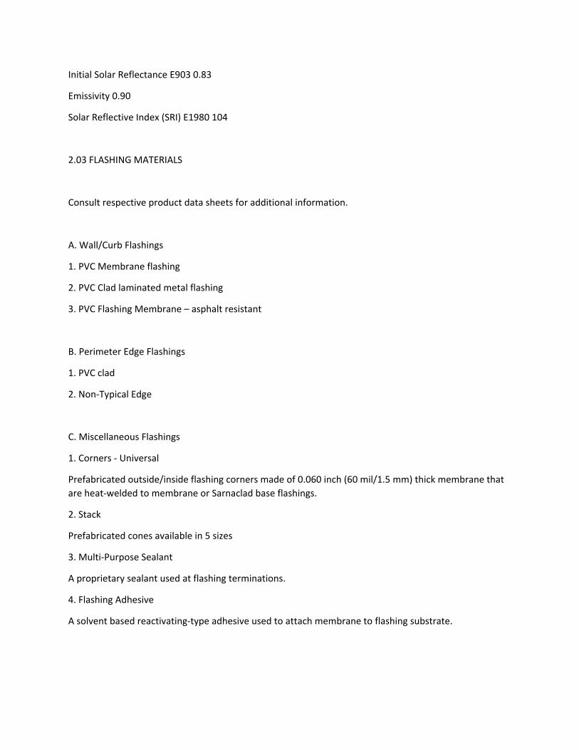
Initial Solar Reflectance E903 0.83
Emissivity 0.90
Solar Reflective Index (SRI) E1980 104
2.03 FLASHING MATERIALS
Consult respective product data sheets for additional information.
A. Wall/Curb Flashings
1. PVC Membrane flashing
2. PVC Clad laminated metal flashing
3. PVC Flashing Membrane – asphalt resistant
B. Perimeter Edge Flashings
1. PVC clad
2. Non‐Typical Edge
C. Miscellaneous Flashings
1. Corners ‐ Universal
Prefabricated outside/inside flashing corners made of 0.060 inch (60 mil/1.5 mm) thick membrane that
are heat‐welded to membrane or Sarnaclad base flashings.
2. Stack
Prefabricated cones available in 5 sizes
3. Multi‐Purpose Sealant
A proprietary sealant used at flashing terminations.
4. Flashing Adhesive
A solvent based reactivating‐type adhesive used to attach membrane to flashing substrate.
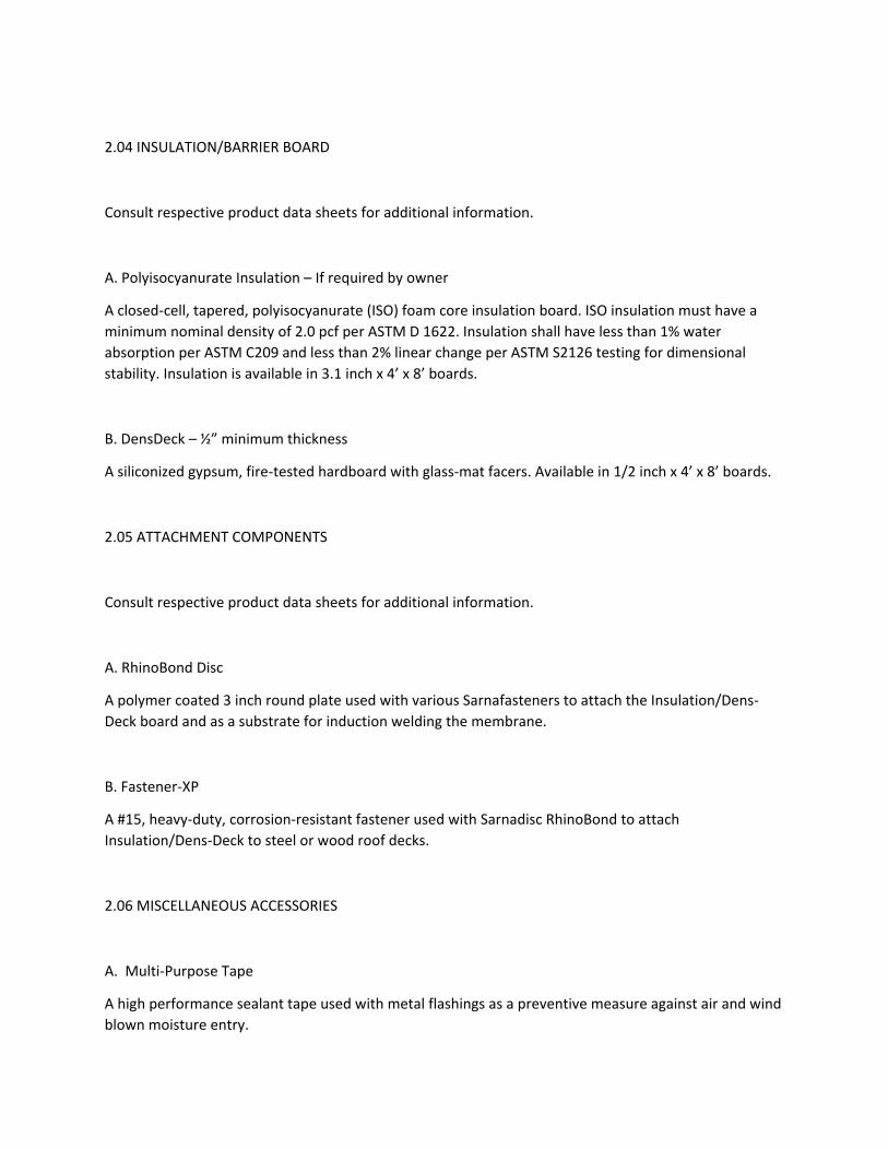
2.04 INSULATION/BARRIER BOARD
Consult respective product data sheets for additional information.
A. Polyisocyanurate Insulation – If required by owner
A closed‐cell, tapered, polyisocyanurate (ISO) foam core insulation board. ISO insulation must have a
minimum nominal density of 2.0 pcf per ASTM D 1622. Insulation shall have less than 1% water
absorption per ASTM C209 and less than 2% linear change per ASTM S2126 testing for dimensional
stability. Insulation is available in 3.1 inch x 4’ x 8’ boards.
B. DensDeck – ½” minimum thickness
A siliconized gypsum, fire‐tested hardboard with glass‐mat facers. Available in 1/2 inch x 4’ x 8’ boards.
2.05 ATTACHMENT COMPONENTS
Consult respective product data sheets for additional information.
A. RhinoBond Disc
A polymer coated 3 inch round plate used with various Sarnafasteners to attach the Insulation/Dens‐
Deck board and as a substrate for induction welding the membrane.
B. Fastener‐XP
A #15, heavy‐duty, corrosion‐resistant fastener used with Sarnadisc RhinoBond to attach
Insulation/Dens‐Deck to steel or wood roof decks.
2.06 MISCELLANEOUS ACCESSORIES
A. Multi‐Purpose Tape
A high performance sealant tape used with metal flashings as a preventive measure against air and wind
blown moisture entry.
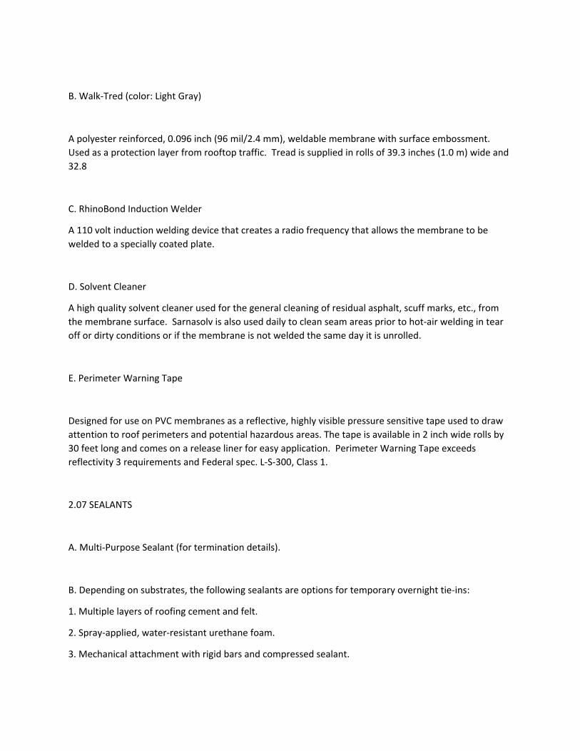
B. Walk‐Tred (color: Light Gray)
A polyester reinforced, 0.096 inch (96 mil/2.4 mm), weldable membrane with surface embossment.
Used as a protection layer from rooftop traffic. Tread is supplied in rolls of 39.3 inches (1.0 m) wide and
32.8
C. RhinoBond Induction Welder
A 110 volt induction welding device that creates a radio frequency that allows the membrane to be
welded to a specially coated plate.
D. Solvent Cleaner
A high quality solvent cleaner used for the general cleaning of residual asphalt, scuff marks, etc., from
the membrane surface. Sarnasolv is also used daily to clean seam areas prior to hot‐air welding in tear
off or dirty conditions or if the membrane is not welded the same day it is unrolled.
E. Perimeter Warning Tape
Designed for use on PVC membranes as a reflective, highly visible pressure sensitive tape used to draw
attention to roof perimeters and potential hazardous areas. The tape is available in 2 inch wide rolls by
30 feet long and comes on a release liner for easy application. Perimeter Warning Tape exceeds
reflectivity 3 requirements and Federal spec. L‐S‐300, Class 1.
2.07 SEALANTS
A. Multi‐Purpose Sealant (for termination details).
B. Depending on substrates, the following sealants are options for temporary overnight tie‐ins:
1. Multiple layers of roofing cement and felt.
2. Spray‐applied, water‐resistant urethane foam.
3. Mechanical attachment with rigid bars and compressed sealant.
2.08 MISCELLANEOUS FASTENERS AND ANCHORS
A. All fasteners, anchors, nails, straps, bars, etc. shall be post‐galvanized steel, aluminum or stainless
steel. Mixing metal types and methods of contact shall be assembled in such a manner as to avoid
galvanic corrosion. Fasteners for attachment of metal to masonry shall be expansion type fasteners
with stainless steel pins. All concrete fasteners and anchors shall have a minimum embedment of 1‐1/4
inch and shall be approved for such use by the fastener manufacturer. All miscellaneous wood fasteners
and anchors used for flashings shall have a minimum embedment of 1 inch and shall be approved for
such use by the fastener manufacturer.
PART 3 ‐ EXECUTION
3.01 PRE‐CONSTRUCTION CONFERENCE
A. The primary contractor shall conduct a pre‐roofing conference before any work begins, so all parties
involved in the roofing system construction, or who may work on or through the roofing system,
understand their obligations with respect to the roofing membrane.
3.02 SUBSTRATE CONDITION
A. Applicator shall be responsible for acceptance or provision of proper substrate to receive new roofing
materials.
B. Applicator shall verify that the work done under related sections meets the following conditions:
1. Roof drains and scuppers have been reconditioned or replaced and installed properly.
2. Roof curbs, nailers, equipment supports, vents and other roof penetrations are properly secured and
prepared to receive new roofing materials.
3. All surfaces are smooth and free of dirt, debris and incompatible materials.
4. All roof surfaces shall be free of water.
3.03 SUBSTRATE INSPECTION
A. A dry, clean and smooth substrate shall be prepared to receive PVC mechanically‐attached roof
system.
B. The substrate shall be clean, smooth, dry, free of flaws, sharp edges, loose and foreign material, oil
and grease. Roofing shall not start until all defects have been corrected.
C. All roof surfaces shall be free of water.
D. PVC shall be applied over compatible and accepted substrates only.
3.04 SUBSTRATE PREPARATION
A. If necessary, accumulations of bitumen or other irregularities shall be scratched and removed so as to
produce a flat, smooth surface. Insulation and Dens‐Deck boards shall lay flat from one board to
another.
B. All wet areas shall be removed and replaced.
C. Surfaces on which the PVC membrane is to be applied shall be compatible, clean, smooth, free of
sharp edges, loose and foreign material, oil, grease and bitumen.
D. When possible, work shall begin at the high point of the roofing area and proceed to the lowest point.
3.05 INSULATION/DENS‐DECK INSTALLATION
General Criteria:
A. Insulation/Dens‐Deck shall be installed according to manufacturer's instructions.
B. Insulation/Dens‐Deck shall be neatly cut to fit around penetrations and projections.
C. Install tapered insulation in accordance with insulation manufacturer's shop drawings.
D. Do not install more Insulation/Dens‐Deck board than can be covered with 72 mil single‐ply PVC
roofing membrane by the end of the day or the onset of inclement weather.
E. Mechanical ‐ Rhinobond Attachment
1. Insulation/Dens‐Deck shall be mechanically fastened to the structural deck with approved membrane
fasteners and RhinoBond Disc according to the manufacturer's and PVC membrane manufacturer’s
recommendations for fastening rates and patterns. The quantity and locations of the fasteners and
plates shall also cause the boards to rest evenly on the roof deck/substrate. Each board shall be
installed tightly against the adjacent boards on all sides.
2. Fasten the Insulation/Dens‐Deck so the RhinoBond disc and fastener XP in a 2 by 2 foot grid pattern
according to PVC Membrane Manufacturer’s and the wind design requirements. Fasteners must be tight
enough that the membrane disc does not turn, but not so tight as to deform the disc.
3. Perimeter and Corner Areas
The perimeter and corner area will be determined by building height and width and other conditions
according to ASCE 7 guidelines, PVC Membrane Manufacturer’s Technical or FM LPDS 1‐29 if insured by
Factory Mutual. To meet the perimeter and corner uplift requirements, increase fastener density by
decreasing the spacing between fastener points in one or both directions. The total tributary area to
each fastener is no more than 60 percent for the perimeter and 40 percent for corners, based on the
field of roof fastening density. See Detail Drawings.
Notes:
a) Perimeter area is defined as the outer boundary of the roof. If the roof is broken into different levels,
each roof area shall be treated as an individual roof with its outer boundary being treated as a
perimeter. Typically, internal expansion joints and firewalls are not considered to be full perimeters.
Refer to Factory Mutual’s Data Sheet 1‐28 for more information.
b) The ridge area is defined as the high point in the roof area formed by two intersecting planes. When
the sum of the slopes is a minimum of 4 inches in 12 inches (30 degrees), each side of the ridge shall be
treated as a perimeter area.
4. Fasteners are to be installed consistently in accordance with fastener manufacturer's
recommendations. Fasteners are to have minimum penetration of 1 inch through the structural deck.
5. Use fastener tools with a depth locator and torque‐limiting attachment as recommended or supplied
by fastener manufacturer to ensure proper installation.
3.06 INSTALLATION OF PVC MEMBRANE
The surface of the Dens‐Deck shall be inspected prior to installation of the PVC roof membrane. The
substrate shall be clean, dry, free from debris and smooth with no surface roughness or contamination.
Broken, delaminated, wet or damaged boards shall be removed and replaced. PVC membrane shall be
attached with fasteners and RhinoBond disc according to PVC membrane manufacturer’s and wind uplift
requirements per ASCE 7 or Factory Mutual.
A. RhinoBond ‐ Membrane Attachment to Structural Deck
1. General
a) PVC full width rolls shall be placed over the installed boards. Membrane overlaps shall be shingled
with the flow of water where possible. Seam overlaps may be placed over disc RhinoBond plate.
Welding of the plate will not be affected.
b) Tack welding of the membrane for purposes of temporary restraint during installation is not
permitted and may result in voiding of warranty. Consult Technical Department for further information.
2. Field, Perimeter and Corner Areas
Over the properly prepared, installed and attached substrate surface following the 2 by 2 foot grid
pattern, PVC full‐width rolls are to be installed so as to properly shed water. See Detail Drawings for
fastener layouts. Refer to FM LPDS 1‐29 for their requirements for perimeter and corner enhancements.
3. Securement Around Rooftop Penetrations
a) Around all perimeters, at the base of walls, drains, curbs, vent pipes, or any other roof penetrations,
fasteners and RhinoBond discs, discs or perimeter bars shall be installed according to perimeter rate of
attachment. Fasteners shall be installed according to the manufacturer’s instructions. Fasteners shall
be installed using the fastener manufacturer’s recommended torque‐sensitive fastening tools with
depth locators. If RhinoBond disc is not used, the fasteners shall clamp the PVC membrane tightly to the
substrate.
b) PVC membrane flashings shall extend 2‐1/2 inches past disc and be hot‐air welded to the PVC deck
membrane.
3.07 RHINOBOND INDUCTION WELDING
B. General
1. Welding equipment shall be provided by or approved by PVC membrane manufacturer. All
mechanics intending to use the equipment shall have successfully completed a training course provided
by a Technical Service Representative prior to welding.
2. All membrane to be welded shall be clean and dry.
C. Induction Welding
1. Activate the weld between membrane and plate using approved portable induction device. The
induction coil must be positioned over the center of the RhinoBond disc, +/‐ 1 inch Portable induction
device must elevate the temperature of the RhinoBond disc from ambient to 400 – 500 degree F. Cycle
time will be affected by available power, use a heavy gauge power cord, at a minimum 12 gauge by 100
feet.
2. When the induction welding cycle is complete, immediately place a Cool & Clamp magnetic weight on
the welded assembly. This device must be left in place for at least 60 seconds.
3.08 HOT‐AIR WELDING OF SEAM OVERLAPS
A. General
1. All seams shall be hot‐air welded. Seam overlaps should be 3 inches wide when automatic machine‐
welding and 4 inches wide when hand‐welding, except for certain details.
2. Welding equipment shall be provided by or approved by PVC membrane manufacturer. All mechanics
intending to use the equipment shall have successfully completed a training course provided by a PVC
Manufacturer Technical Service Representative prior to welding.
3. All membrane to be welded shall be clean and dry.
B. Hand‐Welding
Hand‐welded seams shall be completed in two stages. Hot‐air welding equipment shall be allowed to
warm up for at least one minute prior to welding.
1. The back edge of the seam shall be welded with a narrow but continuous weld to prevent loss of hot
air during the final welding.
2. The nozzle shall be inserted into the seam at a 45 degree angle to the edge of the membrane. Once
the proper welding temperature has been reached and the membrane begins to "flow”, the hand roller
is positioned perpendicular to the nozzle and rolled lightly. For straight seams, the 1‐1/2 inch wide
nozzle is recommended for use. For corners and compound connections, the 3/4 inch wide nozzle shall
be used.
C. Machine Welding
1. Machine welded seams are achieved by the use of PVC membrane automatic welding equipment.
When using this equipment, PVC manufacturer instructions shall be followed and local codes for electric
supply, grounding and over current protection observed. Dedicated circuit house power or a dedicated
portable generator is recommended. No other equipment shall be operated simultaneously off the
generator.
2. Metal tracks may be used over the deck membrane and under the machine welder to minimize or
eliminate wrinkles.
D. Quality Control of Welded Seams
1. The Applicator shall check all welded seams for continuity using a rounded screwdriver. Visible
evidence that welding is proceeding correctly is smoke during the welding operation, shiny membrane
surfaces, and an uninterrupted flow of dark grey material from the underside of the top membrane. On‐
site evaluation of welded seams shall be made daily by the Applicator at locations as directed by the
Owner's Representative or PVC membrane representative. One inch wide cross‐section samples of
welded seams shall be taken at least three times a day. Correct welds display failure from shearing of
the membrane prior to separation of the weld. Each test cut shall be patched by the Applicator at no
extra cost to the Owner.
3.09 MEMBRANE FLASHINGS
All flashings shall be installed concurrently with the roof membrane as the job progresses. No
temporary flashings shall be allowed without the prior written approval of the Owner's Representative
and PVC manufacturer. Approval shall only be for specific locations on specific dates. If any water is
allowed to enter under the newly completed roofing, the affected area shall be removed and replaced
at the Applicator's expense. Flashing shall be adhered to compatible, dry, smooth, and solvent‐resistant
surfaces. Use caution to ensure adhesive fumes are not drawn into the building.
A. Adhesive for Membrane Flashings
1. Over the properly installed and prepared flashing substrate, flashing adhesive shall be applied
according to instructions found on the Product Data Sheet. The adhesive shall be applied in smooth,
even coats with no gaps, globs or similar inconsistencies. Only an area which can be completely covered
in the same day's operations shall be flashed. The bonded sheet shall be pressed firmly in place with a
hand roller.
2. No adhesive shall be applied in seam areas that are to be welded. All panels of membrane shall be
applied in the same manner, overlapping the edges of the panels as required by welding techniques.
B. PVC manufacturer’s requirements and recommendations and the specifications shall be followed. All
material submittals shall have been accepted by PVC Manufacturer prior to installation.
C. All flashings shall extend a minimum of 8 inches above roofing level unless otherwise accepted in
writing by the Owner's Representative and PVC Membrane Manufacturer Technical Department. All
curb flashings will picture frame the penetration; the corners of adjacent sheets will form one corner
where the base flashings meet on the plane of the roof membrane. All flashing will be uniformly
installed at all locations. Failure to picture frame the penetrations will result in the contractor removing
the flashing and redoing the penetration to the satisfaction of the owners representative at no
additional cost to the owner.
D. All flashing membranes shall be consistently adhered to substrates. All interior and exterior corners
and miters shall be cut and hot‐air welded into place. No bitumen shall be in contact with the PVC
membrane.
E. All flashing membranes shall be mechanically fastened along the counter‐flashed top edge with peel
stop at 6‐8 inches on center.
F. PVC flashings shall be terminated according to PVC membrane recommended details.
G. All adhered flashings that exceed 30 inches in height or that of the perimeter Sarnabar spacings shall
receive additional securement. Consult Technical Department for securement methods.
H. All mechanically‐attached flashings that exceed 18 inches in height shall receive additional
securement. Consult approved PVC Manufacturer Technical Department for securement methods.
3.10 PVC CLAD METAL BASE FLASHINGS/EDGE METAL
All flashings shall be installed concurrently with the roof membrane as the job progresses. No
temporary flashings shall be allowed without the prior written approval of the Owner's Representative
and PVC Manufacturer. If any water is allowed to enter under the newly completed roofing due to
incomplete flashings, the affected area shall be removed and replaced at the Applicator's expense.
A. PVC clad metal flashings shall be formed and installed per the Detail Drawings.
1. All metal flashings shall be fastened into solid wood nailers with two rows of post galvanized flat head
annular ring nails, 4 inches on center staggered. Fasteners shall penetrate the nailer a minimum of 1
inch.
2. Metal shall be installed to provide adequate resistance to bending and allow for normal thermal
expansion and contraction.
B. Adjacent sheets of clad shall be spaced 1/4 inch apart. The joint shall be covered with 2 inch wide
aluminum tape. A 4 inch minimum wide strip of PVC flashing membrane shall be hot‐air welded over
the joint. Exercise caution at perimeter of roof. Workers shall follow OSHA safety procedures.
3.11 WALKWAY INSTALLATION
A. Tread Walkway
Roofing membrane to receive tread Walkway shall be clean and dry. Place chalk lines on deck sheet to
indicate location of Walkway. Apply a continuous coat of approved adhesive to the deck sheet and the
back of Walkway in accordance with technical requirements and press Walkway into place with a water‐
filled, foam‐covered lawn roller. Clean the deck membrane in areas to be welded. Hot‐air weld the
entire perimeter of the Walkway to the PVC deck sheet. Check all welds with a rounded screwdriver.
Re‐weld any inconsistencies. Important: Check all existing deck membrane seams that are to be covered
by Walkway with rounded screwdriver and reweld any inconsistencies before Walkway installation. Do
not run Walkway over bars. Tread Walkway shall be installed two (2) courses wide around all roof top
mechanical equipment and at all access and egress locations.
3.12 TEMPORARY CUT‐OFF
All flashings shall be installed concurrently with the roof membrane in order to maintain a watertight
condition as the work progresses. All temporary waterstops shall be constructed to provide a 100
percent watertight seal. The stagger of the board joints shall be made even by installing partial panels
of Insulation/Dens‐Deck. The new membrane shall be carried into the waterstop. Waterstop shall be
sealed to the deck and substrate so that water will not be allowed to travel under the new or existing
roofing. The edge of the membrane shall be sealed in a continuous heavy application of sealant as
described in Section 2.07. When work resumes, the contaminated membrane shall be cut out. All
sealant, contaminated membrane, insulation fillers, etc. shall be removed from the work area and
properly disposed of off site. None of these materials shall be used in the new work.
If inclement weather occurs while a temporary waterstop is in place, the Applicator shall provide the
labor necessary to monitor the situation to maintain a watertight condition.
If any water is allowed to enter under the newly‐completed roofing, the affected area shall be removed
and replaced at the Applicator's expense.
3.13 COMPLETION
Prior to demobilization from the site, the work shall be reviewed by the Owner's Representative and the
Applicator. All defects noted and non‐compliances with the Specifications or the recommendations of
PVC roofing membrane manufacturer shall be itemized in a punch list. These items must be corrected
immediately by the Applicator to the satisfaction of the Owner's Representative and PVC roofing
membrane manufacturer prior to demobilization.
All Warranties referenced in this Specification shall have been submitted and have been accepted at
time of contract award.