Embed Size (px)
Citation preview

SPECIFICATION of work to be done and materials to be used in carrying out the works shown on the accompanying drawings
BTW Hamilton Re-Roof and Alterations Project Specification 517 Angelsea Street, Hamilton, New Zealand Project Ref: 6093
Printed: 23 May 2017
Boon Goldsmith Bhaskar Brebner - Team Architects
Specification built using Masterspec software
Masterspec ID: 136933 - 68522
TABLE OF CONTENTS
1210 PROJECT.1211 DOCUMENTATION1212 COMPLIANCE1213 SELECTIONS1220 GENERAL REQUIREMENTS1233 DOCUMENTS REFERENCED2100 DEMOLITION WORK3320 CONCRETE BLOCK MASONRY3800 TIMBER FRAMING4220 WALL CLADDING4310 ROOFING4422VE VIKING ENVIROCLAD & ENVIROCLAD FBS MEMBRANE4520 ALUMINIUM WINDOWS & DOORS4610 GLAZING4710 THERMAL INSULATION5110 INTERIOR LININGS AND TRIM5230 INTERIOR DOORS & FRAMES6200 TILING6221A ARDEX TILING SOLUTIONS6700 PAINTING7120 WATER SYSTEM7150 SANITARYWARE, TAPWARE & ACCESSORIES7210 GAS SYSTEM7420 SANITARY WASTE SYSTEM7700 ELECTRICAL
3456
111518192123252732343536383941485051525354

1210 PROJECT.
1 GENERAL
1.1 PROJECT
Street address: 517 Anglesea Street, Hamilton Legal description: Lot 1 DP 32977 Site area: 670 m2 Project type: Addition / Internal alteration / Demolition Intended use: Multi use, Commercial and Residential Intended life: Indefinite but not less than 50 years
Re-Roof and Alterations 1.2 PROJECT DESCRIPTION
Any site license LBP's shall have a minimum: Site license in area of practice 1 Bricklaying and Blocklaying 2: Structural masonry Carpentry Roofing 2: Profiled metal roof and/or wall cladding Roofing 4: Roof membrane Plumbing
1.3 LBP REQUIREMENT
1.4 OWNER
Name: BTW Company Mailing address: Level 1, 517 Anglesea Street, Hamilton Telephone: Email: [email protected]
1.5 DESIGNER
Name: Boon Goldsmith Bhaskar Brebner Team Architects Mailing address: 131 Courtenay street, New plymouth Telephone: 06 757 3200 Email: [email protected]
1.6 ENGINEER
Name: BTW Company Mailing address: Level 1, 517 Angelsea Street, Hamilton Telephone: 0800 289 787 Email: [email protected]
1.7 CONTRACTOR
Name: TBC Mailing address: Telephone: Email:
The project has the following unusual or atypical features, which a reasonably experienced contractor may not be aware of, that may present an unexpected hazard or risk during a typical construction process.
Provide particular health and safety procedures and methods to mitigate these hazards or risks, and specifically include them as well as any other health and safety matters in the site Health and Safety requirements (refer to section 1220 GENERAL REQUIREMENTS for site health and safety requirements).
1.8 DESIGN CONSTRUCTION SAFETY MATTERS
ITEM COMMENT Client to undergo asbestos testing
Boon Goldsmith Bhaskar Brebner - Team Architects BTW Hamilton Re-Roof and Alterations136933
© CIL Masterspec May 2017 1210 PROJECT. Page 3

1211 DOCUMENTATION
1 GENERAL
1.1 DRAWINGS
Number Revision Title Architectural Drawing Set 1 For Building Consent
Engineers calculations, Engineers producer statement 1.2 ENGINEERS DOCUMENTS
Acoustic Engineers report 1.3 OTHER DOCUMENTS
Viking Enviroclad Membrane, Ardex waterproofing, GIB Fire rated systems, powerglide lifts, 1.4 MANUFACTURERS LITERATURE
Boon Goldsmith Bhaskar Brebner - Team Architects BTW Hamilton Re-Roof and Alterations136933
© CIL Masterspec May 2017 1211 DOCUMENTATION Page 4

1212 COMPLIANCE
1 GENERAL
1.1 SITE DATA
Soil type: NA (to NZS 3604, 3.2 Soil types) Exposure zone: Zone B (to NZS 3604, 4.2 Exposure zones or E2/AS1 Zone E severe
marine) Wind zone: A (to NZS 3604, table 5.4 Determination of Wind Zone) Earthquake zone: Zone 1 (to NZS 3604, figure 5.4 Earthquake zones)
1.2 BUILDING DATA
Building classification: 2 Importance Level (to NZS 3604, table 1.1 Classification of buildings) Floor live load: 3 KPa (to NZS 3604, table 1.2 Imposed floor live load reference values) Overall height: 9.4 metres (in accordance with NZS 3604, Fig 1.2 Buildings covered by
this Standard) Risk assessment: 9 Total Risk Score (to NZBC E2/AS1, 3.1 Establishing the risk)
Provide Producer Statements for the following � Roofing � Wet area interior waterproofing � Aluminium joinery � Glazing � Plumbing � Gasfitting
Provide Producer Statements in the required form. Where no form is specified provide in the industry/trade standard form. Provide all Producer Statements before the Building Consent Authority carries out the final inspection.
1.3 PRODUCER STATEMENTS
Provide Records of Work for Restricted Building Work: � Structural masonry � Carpentry � Roofing � Membrane roof � Foundations � Plumbing
Refer to the Building Consent for specific requirements. Provide Records of Work in the required form. Provide all Records of Work before the Building Consent Authority carries out the final inspection.
1.4 RECORDS OF WORK
Boon Goldsmith Bhaskar Brebner - Team Architects BTW Hamilton Re-Roof and Alterations136933
© CIL Masterspec May 2017 1212 COMPLIANCE Page 5

1213 SELECTIONS
The following selections are to be read in conjunction with the related work sections, where they are available, and the general sections.
1 GENERAL
<< 2100 DEMOLITION WORK >>
2 SITE
TBC 2.1 DEMOLITION ITEMS FOR REUSE
TBC 2.2 DEMOLITION ITEMS FOR RETURN TO THE OWNER
<< 3320 CONCRETE BLOCK MASONRY >>
3 STRUCTURE
3.1 CONCRETE BLOCK MASONRY
Brand/Type: Firth Bond: Stretcher bond Pointing: To match existing
<< 3800 TIMBER FRAMING >>
3.2 WATERPROOFING TO OPENINGS - CONCRETE MASONRY
Type: NA
3.3 EXTERIOR WALL TIMBER FRAMING
Type/treatment: Radiata pine, Grade SG8, Treated H1.2 Cavity battens: Radiata pine, Treated H3.1 (non-structural) Jamb battens: Radiata pine, Treated H3.1
3.4 ROOF TIMBER FRAMING
Type/treatment: Radiata pine, Grade SG8, Treated H1.2
3.5 ROOF TRUSSES
Type/treatment: NA Truss supplier: NA
3.6 INTERIOR WALL TIMBER FRAMING
Type/treatment: Radiata pine, Grade SG8, Treated H1.2
3.7 EXTERIOR EXPOSED TIMBER
Cladding & trim: Radiata pine, Dressing, Treated H3.1 or Untreated Cedar Structure: Radiata pine, Grade SG8, Treated H3.2 CCA (preservative code 01 or
02) Deck framing & joists: Radiata pine, Grade SG8, Treated H3.2 CCA (preservative code 01 or
02)
3.8 ENGINEERED TIMBER
Location: Behind Composite Cladding - Refer Drawings Type/treatment: H3.2 Treatment
<< 4160 DAMP-PROOFING, UNDERLAYS AND RIGID AIR BARRIERS >> There is no work section specification relating to the following selections
4 ENCLOSURE
4.1 DAMP-PROOF COURSE
Brand/Type: Mirra Black or equal approved
4.2 WALL UNDERLAY/ROOF UNDERLAY
Boon Goldsmith Bhaskar Brebner - Team Architects BTW Hamilton Re-Roof and Alterations136933
© CIL Masterspec May 2017 1213 SELECTIONS Page 6
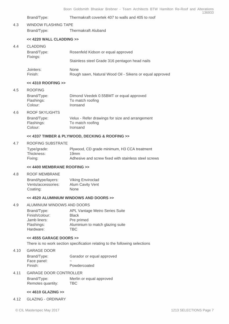
Brand/Type: Thermakraft covertek 407 to walls and 405 to roof
<< 4220 WALL CLADDING >>
4.3 WINDOW FLASHING TAPE
Brand/Type: Thermakraft Aluband
<< 4310 ROOFING >>
4.4 CLADDING
Brand/Type: Rosenfeld Kidson or equal approved Fixings:
Stainless steel Grade 316 pentagon head nails
Jointers: None Finish: Rough sawn, Natural Wood Oil - Sikens or equal approved
4.5 ROOFING
Brand/Type: Dimond Veedek 0.55BMT or equal approved Flashings: To match roofing Colour: Ironsand
<< 4337 TIMBER & PLYWOOD, DECKING & ROOFING >>
4.6 ROOF SKYLIGHTS
Brand/Type: Velux - Refer drawings for size and arrangement Flashings: To match roofing Colour: Ironsand
<< 4400 MEMBRANE ROOFING >>
4.7 ROOFING SUBSTRATE
Type/grade: Plywood, CD grade minimum, H3 CCA treatment Thickness: 19mm Fixing: Adhesive and screw fixed with stainless steel screws
<< 4520 ALUMINIUM WINDOWS AND DOORS >>
4.8 ROOF MEMBRANE
Brand/type/layers: Viking Enviroclad Vents/accessories: Alum Cavity Vent Coating: None
<< 4555 GARAGE DOORS >> There is no work section specification relating to the following selections
4.9 ALUMINIUM WINDOWS AND DOORS
Brand/Type: APL Vantage Metro Series Suite Finish/colour: Black Jamb liners: Pre primed Flashings: Aluminium to match glazing suite Hardware: TBC
4.10 GARAGE DOOR
Brand/Type: Garador or equal approved Face panel: ~ Finish: Powdercoated
<< 4610 GLAZING >>
4.11 GARAGE DOOR CONTROLLER
Brand/Type: Merlin or equal approved Remotes quantity: TBC
4.12 GLAZING - ORDINARY
Boon Goldsmith Bhaskar Brebner - Team Architects BTW Hamilton Re-Roof and Alterations136933
© CIL Masterspec May 2017 1213 SELECTIONS Page 7

Location: Refer Door and Window Schedule Type: Refer Door and Window Schedule
4.13 GLAZING - SAFETY
Location: Refer Door and Window Schedule Type: Refer Door and Window Schedule
<< 4710 THERMAL INSULATION >>
4.14 GLAZING - INSULATING GLASS UNITS
Location: Refer Door and Window Schedule Type: Refer Door and Window Schedule
4.15 WALL INSULATION
Brand/Type: Mammoth Wall Sections R value/Thickness: R 1.9 / 90mm
<< 4820 FLASHINGS >> There is no work section specification relating to the following selections
4.16 CEILING/ROOF INSULATION
Brand/Type: Mammoth Ceiling Blanket R value/Thickness: R 2.9 / 185mm
4.17 FLASHINGS - GENERALLY
Type: 0.55BMT Finished to match roofing or glazing suite
4.18 FLASHINGS - CONCEALED
Type: 0.55BMT Finished to match roofing or glazing suite
<< 5110 INTERIOR LININGS AND TRIM >>
5 INTERIOR
5.1 WALL LININGS
Location: Refer Drawings Brand/Type/thickness: Winstone or equal approved / Standard or Aqualine / 10mm Finish: Level 4 stopped, Paint Finish
5.2 WALL LININGS - PLYWOOD
Location: Top of stair shaft Brand/Type/thickness: CHH or equal approved/ Non treated / 12mm Grade/Finish: CD / Paint Finish Jointer: Negative Detail 5mm gap.
5.3 CEILING LININGS
Location: Refer Drawings Brand/Type/thickness: Winstone or equal approved / Standard ceiling / 13mm Finish: Level 4 stopped, Paint Finished
<< 5230 INTERIOR DOORS & FRAMES >>
5.4 INTERIOR TRIM
Skirtings: Paint Finished Architraves: Paint Finished Scotia: NA
<< 5520 HARDWARE >> There is no work section specification relating to the following selections
5.5 INTERIOR DOORS
Location: Refer Drawings Leaf type/finish: Refer Door and Window Schedule Frame type/finish Refer Door and Window Schedule Hardware: TBC
Boon Goldsmith Bhaskar Brebner - Team Architects BTW Hamilton Re-Roof and Alterations136933
© CIL Masterspec May 2017 1213 SELECTIONS Page 8

~ 5.6 HARDWARE BRAND TYPE
<< 6200 TILING >>
6 FINISH
6.1 TILES
Location: Bathrooms Floor Tile/substrate: TBC / Screed over Concrete floor Wall Tile/substrate: TBC / Villaboard Grout/colour: TBC
<< 6300 FLOOR COVERING >>
6.2 WET AREA WATERPROOFING
Location: Bathrooms Brand/type: Ardex WPM 001
<< 6700 PAINTING >>
6.3 RESILIENT FLOORING (VINYL, LINOLEUM OR RUBBER)
Location: GF Toilets Brand/Type: Jacobsens Tarkett Jointing method: Proprietary Vinyl joint weld Skirting or coving: 100mm coving to aluminium trim Trim or edging: Aluminum trim to finish edge
6.4 EXTERIOR PAINTING
Roof: NA Walls Refer to attached Resene Specification Timber joinery: Refer to attached Resene Specification Pergola: NA
6.5 INTERIOR PAINTING
Walls Refer to attached Resene Specification Ceiling: Refer to attached Resene Specification Doors Refer to attached Resene Specification Cabinetry: NA Trim: Refer to attached Resene Specification
<< 7120 WATER SYSTEM >>
7 SERVICES
<< 7150 SANITARYWARE, TAPWARE & ACCESSORIES >> SELECTIONS TBC
<< 7210 GAS SYSTEM >>
7.1 WATER SYSTEM
Pipework concealed: Behind strapping Exposed internal pipe finish:
None
Water heater type: Internal Gas Infinity Water heater brand/Model
Rinnai Infinity HDi200 Internal
7.2 GAS
Gas mains type: Natural PLG
<< 7410 RAINWATER SPOUTING SYSTEM >>
7.3 GAS APPLIANCES
Brand/type/reference: TBC
7.4 SPOUTING
Boon Goldsmith Bhaskar Brebner - Team Architects BTW Hamilton Re-Roof and Alterations136933
© CIL Masterspec May 2017 1213 SELECTIONS Page 9

Brand/type/size: Marley stratus PVC
<< 7550 HEATING >> There is no work section specification relating to the following selections
7.5 DOWNPIPES
Brand/type/size: Freeflow downpipes or equal approved
<< 7700 ELECTRICAL >>
7.6 SPACE HEATING
Brand/type/reference: TBC
7.7 ELECTRICAL OUTLETS AND SWITCHES
Brand/type/reference: PDL or equal approved
7.8 LIGHT FITTINGS
Brand/type/reference: TBC
7.9 SMOKE ALARMS
Brand/type/reference: Refer Drawings - Cavius or equal approved
8 EXTERNAL
There are no external related selections for this project. 8.1 NO EXTERNAL RELATED SELECTIONS
Boon Goldsmith Bhaskar Brebner - Team Architects BTW Hamilton Re-Roof and Alterations136933
© CIL Masterspec May 2017 1213 SELECTIONS Page 10

1220 GENERAL REQUIREMENTS
1 GENERAL
The works are as described in this specification and shown on the drawings. 1.1 THE WORKS
Owner: The person defined as "owner" in the New Zealand Building Code. Contractor: The person contracted by the owner to carry out the contract.
1.2 PERSONNEL
The site of the works, the site address and the legal description are listed under the sections 1210 PROJECT. Confine access and work to the area of site indicated on the drawings.
1.3 THE SITE
Sections are for reference and convenience only and do not constitute individual trade sections or work elements. Read all sections together and read this section with all other sections.
1.4 SPECIFICATION SECTIONS
1.5 INTERPRETATIONS
Required: Required by the documents, or by a statutory authority. Proprietary: Identifiable by naming the manufacturer, supplier, installer, trade name,
brand name, catalogue or reference number. Approval: Approval in writing. Direction: Direction in writing. Notified: Notified in writing.
The following abbreviations are commonly used throughout the specification: 1.6 ABBREVIATIONS
AS Australian Standard AS/NZS Joint Australian/New Zealand Standard BCA Building Consent Authority BRANZ Building Research Association of New Zealand LBP Licensed Building Practitioner NZBC New Zealand Building Code NZS New Zealand Standard NZS/AS Joint New Zealand/Australian Standard NUO Network Utility Operator OSH Occupational Safety and Health RBW Restricted Building Work TA Territorial Authority
If there are any inconsistencies, errors or omissions in or between documents, the contractor must seek direction in resolving it. Figured dimensions take precedence over scaled dimensions; drawings to a larger scale take precedence over drawings to a smaller scale and drawings take precedence over specification.
1.7 INCONSISTENCIES
A substitution may be proposed where specified products are not available, or if substitute products are brought to the attention of and are considered by the owner as equivalent or superior to those specified. Except where a specified product is not available, the owner is not bound to accept any substitutions. Notify proposed substitution of specified products. Include sufficient information to allow the owner to confirm that the substitution is equivalent or superior to that specified. Advise the owner whether an amendment will or may be required to the Building Consent and the expected costs of such amendment.
1.8 SUBSTITUTIONS
The words "provide" (or "supply") or "fix" if used separately mean "provide and fix" unless explicitly stated otherwise.
1.9 THE WORDS "PROVIDE" OR "FIX"
Manufacturers and suppliers requirements, instructions, specifications or details are those issued by them for their particular material, product or component and are the latest edition.
1.10 MANUFACTURERS AND SUPPLIERS
1.11 REFERENCED DOCUMENTS
Boon Goldsmith Bhaskar Brebner - Team Architects BTW Hamilton Re-Roof and Alterations136933
© CIL Masterspec May 2017 1220 GENERAL REQUIREMENTS Page 11

Reference is made to various New Zealand Building Code (NZBC) acceptable solutions (AS) and verification methods (VM) for criteria and/or methods used to establish compliance with the Building Act 2004. Reference is also made to various Standards produced by Standards New Zealand (NZS, AS/NZS) and to listed Acts, Regulations and various industry codes of practice and practice guides. The latest edition (including amendments and provisional editions) at the date of this specification applies unless stated otherwise. Documents cited both directly and within other cited publications are part of this specification.
This specification takes precedence in the event of it being at variance with and requiring a higher standard than, the cited documents. Resolution of any variance must be confirmed in writing and where Building Consent is affected, the change notified to the BCA for advice as to whether an amendment is required to the Building Consent Authority.
1.12 PRECEDENCE OF REFERENCED DOCUMENTS
It is an offence under the Building Act 2004 to carry out any work not in accordance with the Building Consent. Refer the resolution of matters concerning compliance to the owner for a direction. Where Building Consent is affected refer any change to the BCA for advice as to whether an amendment is required to the Building Consent.
1.13 BUILDING CONSENT COMPLIANCE
Comply with all statutory obligations and regulations of regulatory bodies controlling execution of the works. 1.14 STATUTORY OBLIGATIONS
Obtain the original or copies of the Building Consent form and documents from the owner and keep on site. Liaise with the BCA and/or the building certifier for all required notices and all inspections required during construction to ensure compliance. Return the consent form and documents to the owner on completion.
1.15 BUILDING CONSENT
Do not proceed with work noted on the Building Consent for inspection until it has been inspected and passed by the BCA inspector.
1.16 INSPECTIONS
Provide names and contact detail of LBP's/ key personnel. Prior to Restricted Building Work being carried out, provide names, registrations numbers (where appropriate) and contact detail of LBP's that are required for RBW by the Building Consent Authority as part of the Building Consent. Include the following as applicable:
� Person with the appropriate site license � Carpenter � Registered drainlayer � Registered plumber � Registered gasfitter � Registered electrician � Roofer � Block layer � Bricklayer � External plasterer � External window manufacturer � Waterproof membrane applicator
1.17 KEY PERSONNEL
When Records of Work or producer statements verifying construction are required, for the application for the Code Compliance Certificate, provide copies to both the BCA and the owner. Provide LBP documents and producer statements in the form required by the BCA.
1.18 PRODUCER STATEMENTS AND LBP DOCUMENTATION
Provide Certificates of Compliance for electrical and gas work carried out. 1.19 CERTIFICATE OF COMPLIANCE
Provide documentation that the Owner requires in order to obtain a Code Compliance Certificate for the consented work.
1.20 CODE COMPLIANCE CERTIFICATE
Where specific trade guarantees/warranties are offered covering materials and/or execution of proprietary products or complete installations, or are required as a condition of Building Consent, provide guarantees/warranties to the owner.
1.21 TRADE GUARANTEES AND WARRANTIES
1.22 SITE ACCOMMODATION
Boon Goldsmith Bhaskar Brebner - Team Architects BTW Hamilton Re-Roof and Alterations136933
© CIL Masterspec May 2017 1220 GENERAL REQUIREMENTS Page 12

Provide, erect and maintain scaffolding, sheds, toilets, water, power and hoardings. Allow for cartage, craneage, plant hire and storage. Arrange for temporary works and services necessary for the completion of the works.
Make the works safe and provide and maintain a safe working environment, to the requirements of the Health and Safety at Work Act 2015. Ensure that all those working on or visiting the site are aware of the rules governing site safety, are properly supervised and are not unnecessarily exposed to hazards and risks.
1.23 HEALTH AND SAFETY
Protect parts of the work liable to damage until completion of the works. Take all precautions necessary to protect the works from damage by unauthorised entry or inclement weather. Brace and support all parts of the works against damage during construction.
1.24 PROTECT THE WORKS
Provide temporary storage areas and protective covers and screens. Fillet stack and protect all framing and structural members from moisture and contamination. Completely protect finishing materials from the weather and damage and store in accordance with the manufacturer's requirements. Protect fabricated elements from the weather and damage, and store in accordance with suppliers requirements.
1.25 STORAGE AND PROTECTION
Report immediately the finding of any fossils, antiquities, pre-1900 items, or objects of value. Ensure they remain undisturbed until approval is given for their removal.
1.26 ANTIQUITIES AND ITEMS OF VALUE AND INTEREST
All directions and approvals in writing. 1.27 MEANS OF COMMUNICATION
Provide a programme for the contract works, including the work of separate contractors being carried out concurrently with this contract. Form of programme: A dated bar chart, identifying the contract work's critical path and all key dates for the provision of labour, materials and elements. Supply a copy of the programme, and any updates to the owner.
1.28 PROGRAMME
Work on site is restricted to between 0800 to 1800, Monday to Friday, excluding statutory holidays. Work outside these hours may be permitted, with prior approval in writing by the owner.
1.29 WORKING HOURS
Do not: � smoke on site � light rubbish fires on the site � bring dogs on to or near the site � bring radios/audio players on to the site.
1.30 RESTRICTIONS
Carry out and record regular checks of material quality and accuracy. Provide all necessary materials, equipment, plant, attendances, supervision, inspections and programming to ensure required standards are met.
1.31 QUALITY ASSURANCE
Prevent damage and nuisance from water, fire, smoke, vehicles, dust, rubbish, noise and other causes resulting from the contract works. Comply with the requirements of the TA and relevant Acts and Standards.
1.32 DAMAGE AND NUISANCE
Set out the works to conform with the drawings. Establish a permanent site datum to confirm the existing ground floor level and its relationship to other existing and new building levels.
1.33 SET-OUT AND DATUM
Conform to the requirements of this specification. Ensure work is level, plumb, and true to line and face. Employ only experienced workers familiar with the materials and techniques specified.
1.34 EXECUTION OF THE WORK
Use only new materials and products, unless stated otherwise, of the specified quality and complying with cited documents.
1.35 MATERIALS AND PRODUCTS
Ensure all parts of a construction or finish are compatible and their individual use approved by the manufacturers and suppliers of other parts of the system. Source all parts of a system from a single manufacturer or supplier.
1.36 COMPATIBILITY
Boon Goldsmith Bhaskar Brebner - Team Architects BTW Hamilton Re-Roof and Alterations136933
© CIL Masterspec May 2017 1220 GENERAL REQUIREMENTS Page 13

Ensure completed building services are operational, with temporary labelling removed, required labelling fixed and service instructions provided.
1.37 COMPLETE ALL SERVICES
Regularly clear away trade debris, unused materials and elements from the site. On completion of the work leave the building clean and ready for occupancy, with all services operating and mechanical parts in good working order. Remove temporary markings, coverings and protective wrappings.
1.38 CLEAR AWAY
Clean and wash down external surfaces to remove dirt, debris and marking. Clean interior surfaces including floors, glass, cabinetwork, joinery, sanitary and hardware items.
1.39 CLEAN
Boon Goldsmith Bhaskar Brebner - Team Architects BTW Hamilton Re-Roof and Alterations136933
© CIL Masterspec May 2017 1220 GENERAL REQUIREMENTS Page 14

1233 DOCUMENTS REFERENCED
Documents listed below are, when referred to in the text, part of this specification. However, this specification takes precedence in the event of it being at variance with and requiring a higher standard than any cited document.
1 GENERAL
Building Act 2004 Gas (Safety and Measurement) Regulations 2010 Health and Safety at Work Act 2015 Health and Safety at Work (Asbestos) Regulations 2016 Electricity (Safety) Regulations 2010 (Reprint as at 4 April 2016) Plumbers, Gasfitters and Drainlayers Act 2006
1.1 ACTS AND REGULATIONS
1.2 NEW ZEALAND BUILDING CODE VERIFICATION METHODS
NZBC E2/VM1 External moisture NZBC G12/VM1 Water supplies
1.3 NEW ZEALAND BUILDING CODE ACCEPTABLE SOLUTIONS
NZBC B1/AS1 Structure - general NZBC B2/AS1 Durability NZBC C/AS1-AS7 Protection from fire NZBC D1/AS1 Access routes NZBC E1/AS1 Surface water NZBC E2/AS1 External moisture NZBC E2/AS3 External moisture NZBC F2/AS1 Hazardous building materials NZBC F7/AS1 Domestic smoke alarms NZBC G1/AS1 Personal hygiene NZBC G10/AS1 Piped services - Gas NZBC G11/AS1 Gas as an energy source NZBC G12/AS1 Water supplies NZBC G13/AS2 Foul water - Drainage
1.4 NEW ZEALAND STANDARDS
Boon Goldsmith Bhaskar Brebner - Team Architects BTW Hamilton Re-Roof and Alterations136933
© CIL Masterspec May 2017 1233 DOCUMENTS REFERENCED Page 15

AS/NZS 1604.3 Specification for preservative treatment - Plywood NZS/AS 1884 Floor coverings - Resilient sheet and tiles - Installation practices AS/NZS 2269.0 Plywood - Structural - Specifications AS/NZS 2455.1 Textile floor coverings - Installation practice - General AS/NZS 2455.2 Textile floor coverings - installation practice - Carpet tiles AS/NZS 2589 Gypsum linings - Application and finishing AS/NZS 2642.2 Polybutylene pipe systems - Polybutylene pipe for hot and cold water
applications AS/NZS 2699.1 Built-in components for masonry construction Wall ties AS/NZS 3000 Electrical installations (known as the Australian/NZ Wiring Rules) NZS 3101.1 Concrete structures standard NZS 3103 Sands for mortars and plasters NZS 3104 Specification for concrete production NZS 3109 Concrete construction NZS 3114 Concrete surface finishes AS/NZS 3500.2 Plumbing and drainage - Sanitary plumbing and drainage NZS 3501 Specification for copper tubes for water, gas and sanitation NZS 3602 Timber and wood-based products for use in building NZS 3603 Timber structures standard NZS 3604 Timber-framed buildings NZS 3622 Verification of timber properties NZS 3631 New Zealand national timber grading rules AS/NZS 4130 Polyethylene (PE) pipes for pressure applications NZS 4210 Masonry construction materials and workmanship NZS 4211 Specification for the performance of windows NZS 4218 Thermal insulation - Housing and small buildings NZS 4223.1 Glazing in buildings - Glass selection and glazing NZS 4223.2 Glazing in buildings - Insulating glass units NZS 4223.3 Glazing in buildings - Human impact safety requirements NZS 4223.4 Glazing in buildings - Wind, dead, snow and live actions NZS 4229 Concrete masonry buildings not requiring specific engineering design NZS 4246 Energy efficiency - Installing bulk thermal insulation in residential buildings NZS 4251.1 Solid plastering - Cement plasters for walls, ceilings and soffits AS/NZS 4666 Insulating glass units AS/NZS 4671 Steel reinforcing materials AS/NZS 4858 Wet area membranes AS/NZS 5601.1 Gas installations - general installations NZS 6803 Acoustics - Construction noise
Weathertight Solutions Vol. 2: Stucco Good practice guide: Tiling Good practice guide: Membrane roofing Bulletin 441 - Sealed joints in external claddings - 2. Sealants Bulletin 519 - Fasteners selection
1.5 BUILDING RESEARCH ASSOCIATION OF NEW ZEALAND (BRANZ)
Cement & Concrete Association of New Zealand � CCANZ CP 01: Code of practice for weathertight concrete and concrete masonry construction
WorkSafe New Zealand (OSH)
� Good Practice Guidelines - Excavation Safety � Repainting lead based paints � Management and Removal of Asbestos (Approved CoP)
Waterproofing Membrane Association Inc.
� WMAI CoPTM: Code of practice for torch-on membrane systems for roofs and decks New Zealand Demolition and Asbestos Association (NZDAA)
� Best Practice Guideline for Demolition in New Zealand. New Zealand Metal Roofing Manufacturers Inc
� NZMRM COP: NZ Metal roof and wall cladding: Code of practice Window Association of New Zealand Incorporated (WANZ)
1.6 OTHER DOCUMENTS
Boon Goldsmith Bhaskar Brebner - Team Architects BTW Hamilton Re-Roof and Alterations136933
© CIL Masterspec May 2017 1233 DOCUMENTS REFERENCED Page 16

� WANZ PQAS: Powder Coating Quality Assurance System � WANZ Installation Guide: The WANZ Guide to Window Installation as described in E2/AS1 Amendment
6.
Boon Goldsmith Bhaskar Brebner - Team Architects BTW Hamilton Re-Roof and Alterations136933
© CIL Masterspec May 2017 1233 DOCUMENTS REFERENCED Page 17

2100 DEMOLITION WORK
Refer to 1213 SELECTIONS/drawings for specific product, material, accessories and finish selections.
1 GENERAL
Carry out work using persons competent and experienced in the trade. 1.1 QUALIFICATIONS
Carry out a thorough survey and examination of the building to ensure the extent, sequence, technique and method of demolition proposed can be safely and efficiently carried out.
1.2 SURVEY EXISTING BUILDING
Conform with the Health and Safety at Work Act 2015 and WorkSafe Management and Removal of Asbestos (Approved CoP)
1.3 HEALTH AND SAFETY
Take all precautions necessary to minimise nuisance caused by dust, dirt, rubbish and water. 1.4 NUISANCE
Refer to NZS 6803, table 2, Recommended upper limits for construction noise… for the allowable upper limits of construction work noise in residential areas over the various time periods. Use silenced and noise insulated plant to ensure compliance.
1.5 NOISE
2 PRODUCTS
Material from the demolition becomes the property of the contractor except for items designated for reuse or removal by others. Remove redundant materials from the site as work proceeds.
2.1 MATERIAL FROM DEMOLITION
3 EXECUTION
Before commencing demolition, disconnect services and remove associated fittings and equipment. 3.1 DISCONNECT SERVICES
Protect retained parts of existing buildings, site and site structures, trees and shrubs. 3.2 PROTECTION
Support and brace the existing structure during the cutting of new openings or the replacement of structural parts. Prevent debris from overloading any part of the structure. Do not remove supports until the new work is strong enough to support the existing structure. Ensure all work remains structurally stable and sound.
3.3 SUPPORT
Erect screens to maintain security and to prevent penetration of weather, dust and dirt. 3.4 TEMPORARY SCREENS
Prevent access by unauthorised persons. Illuminate and protect all holes, unsafe buildings and other hazards. Leave site and buildings safe at the close of each day's work.
3.5 SITE SAFETY
Where demolition work includes contact with or removal of material containing asbestos, conform with the, Health and Safety at Work (Asbestos) Regulations 2016, WorkSafe NZ requirements including WorkSafe Management and Removal of Asbestos (Approved CoP).
3.6 ASBESTOS
Boon Goldsmith Bhaskar Brebner - Team Architects BTW Hamilton Re-Roof and Alterations136933
© CIL Masterspec May 2017 2100 DEMOLITION WORK Page 18

3320 CONCRETE BLOCK MASONRY
Refer to 1213 SELECTIONS/drawings for specific product, material, accessories and finish selections.
1 GENERAL
Use experienced competent registered masons familiar with the materials and techniques specified. Work to be carried out by or supervised by the appropriate LBP.
1.1 QUALIFICATIONS
Call for inspection of the work at critical stages including set out, reinforcing, and the time prior to and during grouting. All as set out in NZS 4210, section 1.4 Inspection.
1.2 INSPECTION
Carry out required tests in accordance with NZS 4210, appendix 2A, Compressive strength tests for mortar and grout. Keep accurate records relating to strength and quality of materials used in the construction, and make the information available to the BCA inspector on request.
1.3 TESTS AND RECORDS
Ensure that, mortar, built in components and reinforcement cover are to NZS 4210, table 2.E1 Masonry durability requirements, for the location and the Exposure Zone (refer 1212 COMPLIANCE). To use the table, exposure zones in NZS 3604 comparable with NZS 3101 (in brackets) are; Zone D (B2), Zone C (B1), Zone B (A2), Closed Interior (A1), Walls against earth (B2), Geothermal hotspots (U), and NZBC E2/AS1 Zone E (C).
1.4 DURABILITY
2 PRODUCTS
2.1 ACCESSORIES
Reinforcement: To AS/NZS 4671 minimum 300E deformed mild steel except for ties in plain round mild steel and as detailed. For slab mesh refer to Concrete Work section.
Mortar: Sand to NZS 3103. Chloride levels not exceeding 0.04% by dry weight of sand. Mortar to NZS 4210, section 2.2 Mortar. Compressive strength of not less than 12.5 MPa.
Grout: To NZS 4210, section 2.3 Grout. Spread value 450 - 530mm. Water: From local authority supply.
3 EXECUTION
Store masonry clear of the ground, under cover and well ventilated until placed in the work. Ensure masonry units are air dry prior to laying.
3.1 STORAGE
Ensure the base concrete is true to line and level, requiring a base mortar bed of 10mm (minimum) to 20mm (maximum).
3.2 CHECK BASE CONCRETE
Before commencing masonry laying check the location of starter reinforcement by measure or by a dry trial lay up of the first course. Do not correct misplacement by cranking bars; obtain direction.
3.3 STARTER POSITIONS
Detailed, bent and placed in accordance with NZS 4210. Refer to drawings for details of reinforcement and extent of grout filling. Minimum cover as required for reinforced concrete, with grout and masonry work treated as a homogeneous material. Maintain reinforcing bars for retaining walls a minimum of 15mm and for other concrete masonry, a minimum of 6mm, from the masonry face, with the space filled with grout. For slab mesh refer to Concrete Work section.
3.4 INSTALL REINFORCEMENT
Construct within the tolerances set out in NZS 4210, clauses 2.6.5 Tolerances and 2.7.1 General. Lay masonry units with bedding of consistent thickness throughout.
3.5 TOLERANCES
3.6 LAY MASONRY UNITS
Boon Goldsmith Bhaskar Brebner - Team Architects BTW Hamilton Re-Roof and Alterations136933
© CIL Masterspec May 2017 3320 CONCRETE BLOCK MASONRY Page 19

Execution generally to NZS 4210, NZS 4229 as modified by NZBC E2/AS3 (CCANZ CP 01). Ensure consistent, fully filled and tooled joints. Where walls are reinforced, prevent mortar droppings from entering the cells being grouted. Provide clean out holes at base of wall, unless "low lift" (NZS 4210) grouting is used. Ensure reinforcement is accurately placed and tied. Lay in regular stretcher bond with all necessary special units and sill units. Cut masonry, if necessary, true and square without chipping.
Protect fair-faced masonry walls, keeping them clear of mortar droppings, grout splashes, or stains. 3.7 PROTECTION
Not exceeding 10mm thick, or less than 8mm when the masonry units are bedded in. Joints tooled concave. 3.8 MASONRY JOINTS
Locate at major changes of wall height or thickness, at openings, and at not more than 6 metre centres, or, as shown on the drawings.
3.9 CONTROL JOINTS
Provide sufficient temporary lateral bracing to ensure stability until the final construction is in place. 3.10 BRACING
Inspect walls prior to grouting. Ensure cells are clean and reinforcement is correctly placed. Grout all masonry cells below finished grades, all cells in retaining walls and all cells containing reinforcing. Use procedures set out in NZS 4210.
3.11 GROUTING OF CELLS
Form and treat construction joints between grout pours and between masonry walls and hardened concrete work to ensure bonding occurs. Comply with NZS 4210, section 2.16 Horizontal construction joints.
3.12 CONSTRUCTION JOINTS
Mortar in components such as sills, copings, lintels, and steps, as work proceeds. Build in plugs, bolts, ties, metal flashings, dowels, fastenings and fixings as required and as shown on the drawings.
3.13 BUILD IN
Clean off mortar splashes and grout spills as they occur, making good any damage at the same time. Clean down masonry and remove waste material from adjoining surfaces and floors.
3.14 CLEANING
Boon Goldsmith Bhaskar Brebner - Team Architects BTW Hamilton Re-Roof and Alterations136933
© CIL Masterspec May 2017 3320 CONCRETE BLOCK MASONRY Page 20

3800 TIMBER FRAMING
Refer to 1213 SELECTIONS/drawings for specific product, material, accessories and finish selections. Use experienced competent carpenter familiar with the materials and techniques specified. Work to be carried out by or supervised by the appropriate LBP.
1 GENERAL
2 PRODUCTS
Species, grade and level of treatment to NZBC B2/AS1, NZS 3602, tables 1 to 3 Requirements for wood-based building components…, and moisture content to NZS 3602, table 4 Allowable moisture content….. Structural Grade (SG) to NZS 3604, NZS 3622 with properties to NZS 3603.
2.1 TIMBER FRAMING GENERALLY
2.2 ACCESSORIES
Damp-proof course: High impact embossed polyethylene Stud straps Polypropylene tape run horizontal at 300mm centres over flexible wall
underlay, for drained cavities with stud spacings greater than 450mm. Nails, bolts and screws: Steel, stainless steel, galvanized steel of pattern to suit the location and
to BRANZ BU 519: Fasteners selection. To NZS 3604, 4 Durability and NZBC E2/AS1.
Nail plates connectors: Stainless steel and/or galvanized steel toothed or nailed plates to the plate manufacturer's design for the particular locations as shown on the drawings and to NZS 3604, 4 Durability. Galvanized steel and stainless steel connectors and brackets to the connector manufacturer's design for locations shown on drawings and to NZS 3604, 4 Durability and NZBC E2/AS1
Corrosion risk For exterior timber, timber in damp areas and timber subject to occasional wetting, use only stainless steel (or equivalent) fixings and connectors, when the timber is treated with; Copper Azole (CuAz, Preservative code 58), Alkaline Copper Quaternary (ACQ, Preservative code 90), Micronise Copper Azole (code 88) or Micronised Copper Quaternary (code 89). For interior timber, treated with copper-based timber preservatives (H3.2 or higher), use a minimum of hot-dipped galvanized steel fixings and fasteners.
3 EXECUTION
Provide and fix blocks, nogs, openings and other items as required by others. 3.1 ATTENDANCE
Maximum allowable moisture content to NZS 3602, table 4 Allowable moisture content…, for framing supporting interior linings:
3.2 MOISTURE CONTENT
Framing at erection 24% Framing at enclosure 20% Framing at lining 16%
To NZS 3604 except as varied in this specification. To include those methods, practices and processes contained in the unit standards for the National Certificate in Carpentry and the National Certificate in Joinery (cabinetry, exterior joinery, stairs). Set out framing in accordance with the requirements of NZS 3604 and as required to support sheet linings and claddings.
3.3 EXECUTION GENERALLY
Floors and bottom plates framed and fastened to NZS 3604, 7 Floors. Frame walls to required loading and bracing complete with lintels, sills and nogs, all fabricated and fastened to NZS 3604, 8 Walls. Frame roof to required loading and bracing complete with valley boards, ridge boards and purlins to NZS 3604, 10 Roof framing. Design and fit roof trusses complete with anchorage. All fabricated and fastened to NZS 3604, 9 Posts, and NZS 3604, 10 Roof framing.
3.4 INSTALL FLOOR, WALL AND ROOF FRAMING
3.5 BATTENS
Boon Goldsmith Bhaskar Brebner - Team Architects BTW Hamilton Re-Roof and Alterations136933
© CIL Masterspec May 2017 3800 TIMBER FRAMING Page 21

For drained cavity construction nominal 20mm H3.1 cavity battens (non-structural) to NZBC E2/AS1, 9.1.8.4 Cavity battens. For direct fix cladding window and door openings nominal 20mm H3.1 jamb battens to NZBC E2/AS1, Fig. 72A.
Boon Goldsmith Bhaskar Brebner - Team Architects BTW Hamilton Re-Roof and Alterations136933
© CIL Masterspec May 2017 3800 TIMBER FRAMING Page 22

4220 WALL CLADDING
Refer to 1213 SELECTIONS/drawings for specific product, material, accessories and finish selections.
1 GENERAL
Carry out work using persons competent and experienced in the trade. 1.1 QUALIFICATIONS
2 PRODUCTS
As selected, or radiata pine to NZS 3631 for grading and to NZS 3602, table 2 Requirements for wood-based building components…, for selection and treatment.
2.1 TIMBER WEATHERBOARD
Cellulose cement autoclaved sheets. 2.2 FIBRE CEMENT SOFFIT LINING
As selected, or radiata pine to NZS 3631 for grading and to NZS 3602, table 2 Requirements for wood-based building components…, for selection and treatment.
2.3 TIMBER FASCIAS AND BARGE BOARDS
2.4 ACCESSORIES
Wall underlay: Refer Selections Rigid Air Barriers: None Jointers: To suit cladding type and thickness. Nails, screws, fastenings:
Metal, size and pattern, to cladding manufacturer's requirements and complying with the relevant aspects of NZS 3604, section 4: Durability and E2/AS1.
3 EXECUTION
Maximum allowable moisture content to NZS 3602, table 4 Allowable moisture content…. 3.1 MOISTURE CONTENT
To NZBC E2/AS1 except as varied in this specification. Execution to include those methods, practices and processes contained in the unit standards for the National Certificate in Carpentry and the National Certificate in Joinery (cabinetry, exterior joinery, stairs).
3.2 EXECUTION GENERALLY
Fix to the manufacturer's requirements. Refer to 1213 SELECTIONS for type. 3.3 INSTALL WALL UNDERLAY/RIGID AIR BARRIER
As specified in the section 3800 TIMBER FRAMING, to suit the selected wall cladding and construction type. 3.4 CAVITY BATTENS OR JAMB BATTENS
Prime (for opaque finish) or seal (for clear finish) front and back faces, edges and end grain (minimum 2 coats) before fixing weatherboards and exterior trim.
3.5 PRIME OR SEAL TIMBER WEATHERBOARDS
Install level, true to line and face, to NZBC E2/AS1, 9.4 Timber weatherboards. 3.6 INSTALL TIMBER WEATHERBOARDS
Cut sheets dry and scribe fit to fully support all edges and joints. Nail and drill for and insert fasteners to the sheet manufacturer's requirements. Fit complete with jointers and capping moulds. Refer to the cladding manufacturer's literature for fixing details and fixings durability requirements to NZS 3604, section 4 Durability.
3.7 INSTALL FIBRE CEMENT SOFFITS
Install timber fascias, barge boards, facings, beads, trim and enclosures level, true to line and face, with all end grain sealed and joints mitred.
3.8 INSTALL EXTERIOR TIMBER FINISHINGS
Install flashings, covers and soakers as detailed on the drawings and to NZBC E2/AS1, 4.0 Flashings. 3.9 INSTALL FLASHINGS
Selection and use of sealants to follow BRANZ BU 601: Sealants for cladding joints. 3.10 USE OF SEALANTS
Boon Goldsmith Bhaskar Brebner - Team Architects BTW Hamilton Re-Roof and Alterations136933
© CIL Masterspec May 2017 4220 WALL CLADDING Page 23

Complete all flashings, finishings and trim so the cladding system is completely weathertight. 3.11 COMPLETE
Boon Goldsmith Bhaskar Brebner - Team Architects BTW Hamilton Re-Roof and Alterations136933
© CIL Masterspec May 2017 4220 WALL CLADDING Page 24

4310 ROOFING
Refer to 1213 SELECTIONS/drawings for specific product, material, accessories and finish selections.
1 GENERAL
Use experienced competent roofers familiar with the materials and techniques specified. Work to be carried out by or supervised by the appropriate LBP.
1.1 QUALIFICATIONS
Use fixings and methods capable of sustaining the loads appropriate to the area as set out in NZS 3604, section 5 Bracing design, and confirmed under 1212 COMPLIANCE.
1.2 WIND AND EARTHQUAKE LOADINGS
2 PRODUCTS
Profile, metal and finish as selected. Accessories, cappings, flashings and fixings to match and to the roofing manufacturer's requirements.
2.1 PROFILED METAL
2.2 ACCESSORIES
Tile battens: Douglas fir or radiata pine, SG6, treated H1.2, size, spacing and fixing to NZS 3604, table 10.12, Tile battens for all wind zones.
Roof underlays: As selected. Nails, screws, fastenings:
Metal, size and pattern, to roofing manufacturer's requirements and complying with the relevant aspects of NZS 3604, section 4 Durability and NZBC E2/AS1.
Flashings: As required.
3 EXECUTION
Stack roofing and accessories on clean, level areas of the site. Cover and protect from damage and from weather until ready to fix in place.
3.1 STORAGE
Set out the planned layout before fixing commences, to ensure true lines and the correct relationship to module, grid and roof features. Overlaps to face away from prevailing wind direction.
3.2 SET-OUT
Lay and fix to NZBC E2/AS1, 8.1.5 Roof Underlays. 3.3 LAY ROOF UNDERLAY
Take care to avoid damaging pre-finished roofing both during and after fixing. Mark only with chalk or spirit-based pen. Wear only soft-soled shoes on the finished surface. Remove metal filings daily.
3.4 TAKE CARE
Use cutting tools recommended by the roofing manufacturer. Fold ends and seal cut edges to the roofing manufacturer's requirements. Fix complete with matching accessories, flashed to roof features and penetrations; all in accordance with NZ metal roof and wall cladding code of practice and NZBC E2/AS1: 8.4 Profiled metal roof cladding.
3.5 INSTALL PROFILED METAL
Check that the trimmed openings are formed and constructed to suit. Install and fix roof windows/lights/skylights in accordance with the manufacturer's installation instructions. Install flashings and overflashings as detailed and as required to make the installation completely weatherproof. Install selected accessories and hardware. Install and complete operating systems.
3.6 INSTALL ROOF WINDOWS/ROOFLIGHTS/SKYLIGHTS
Refer to the roofing manufacturer's literature for fixing details and to NZS 3604 for fixings durability requirements. Select and use sealants only as recommended by the roofing manufacturer.
3.7 FIXINGS AND SEALANTS
Provide apron, verge and ridge flashings. Install and fix as detailed and to the roofing manufacturer's details and to comply with NZBC E2/AS1, 4.0 Flashings, NZBC E2/AS1: 5.0 Roof/wall junctions, and NZBC E2/AS1: 6.0 Parapets.
3.8 INSTALL COVERS AND FLASHINGS
3.9 PENETRATIONS
Boon Goldsmith Bhaskar Brebner - Team Architects BTW Hamilton Re-Roof and Alterations136933
© CIL Masterspec May 2017 4310 ROOFING Page 25

Flash and overflash penetrations through the roof. Fit proprietary boots to pipework penetrations.
Ensure the work is complete with flashings, undercloaks, valleys, ridges and hips properly installed so the finished roof is completely weathertight.
3.10 COMPLETE
Clear trade debris and unused materials from the roof and surrounds regularly during the work and at completion. Sweep down the completed roof and flush out spoutings, gutters and rainwater pipes.
3.11 CLEAR
Boon Goldsmith Bhaskar Brebner - Team Architects BTW Hamilton Re-Roof and Alterations136933
© CIL Masterspec May 2017 4310 ROOFING Page 26

4422VE VIKING ENVIROCLAD & ENVIROCLAD FBS MEMBRANE
This section relates to Viking Enviroclad membrane and Viking Enviroclad FBS (fleece backed) membrane system: It includes Enviroclad applied as a single layer membrane and Enviroclad FBS incorporating a polyester fibre fleece-backing;
� suitable for industrial, commercial and residential roofing and decking applications
1 GENERAL
Refer to ~ for ~. 1.1 RELATED WORK
Refer to the general section 1232 INTERPRETATION & DEFINITIONS for abbreviations and definitions used throughout the specification. The following abbreviations apply specifically to this section
Documents
1.2 ABBREVIATIONS AND DEFINITIONS
TPO Thermoplastic polyolefin FBS Fleece-back system
Refer to the general section 1233 REFERENCED DOCUMENTS. The following documents are specifically referred to in this section:
1.3 DOCUMENTS
NZBC E2/AS1 External moisture AS/NZS 2269.0 Plywood - Structural - Specifications
Manufacturer's and supplier's documents relating to this part of the work: Viking Waterproofing Membrane Systems manual Viking Enviroclad Plywood Substrate Checklist Viking Concrete Substrate Checklist Viking Enviroclad Standard Details Viking Enviroclad Applicator Manual BRANZ Appraisal 656 - Enviroclad Roofing Membrane CodeMark Certificate Number 30058 Rev B - Viking Enviroclad Roofing and Deck Membrane System Copies of the above literature are available from Viking Roofspec
Warranties
1.4 MANUFACTURER/SUPPLIER DOCUMENTS
Web: www.vikingroofspec.co.nz Email: [email protected] Telephone: 0800 729 799 Facsimile: 0800 729 788
Provide a material manufacturer/supplier warranty:
� Provide this warranty on the Viking Roofing standard form. � Commence the warranty from the date of completion of fixing.
Refer to the section 1237 WARRANTIES for additional requirements.
1.5 WARRANTY - MANUFACTURER/SUPPLIER
20 years: For Viking Enviroclad Membrane 20 years: For Viking Enviroclad FBS Membrane
Provide an installer/applicator warranty:
� Provide this warranty in the Viking Enviroclad Membrane Product Warranty on standard form. � Commence the warranty from the date of completion of fixing.
1.6 WARRANTY - INSTALLER/APPLICATOR
5 years: For Enviroclad membrane when installed by Viking approved applicator 5 years: For Enviroclad FBS membrane when installed by Viking approved
applicator
Boon Goldsmith Bhaskar Brebner - Team Architects BTW Hamilton Re-Roof and Alterations136933
© CIL Masterspec May 2017 4422VE VIKING ENVIROCLAD & ENVIROCLAD FBS MEMBRANE Page 27

Refer to the section 1237 WARRANTIES for additional requirements.
Provide a Viking Full System Warranty for materials and installation:
� Register with Viking Roofspec prior to installation. � Approved Applicator must hold d current Stage 3 Viking Roofspec Licence. � Provide this warranty on the Viking Full System Warranty job completion form. � Commence the warranty from the date of completion of fixing.
Refer to the section 1237 WARRANTIES for additional requirements.
Requirements
1.7 WARRANTY - VIKING FULL SYSTEM WARRANTY ON APPLICATION
20 years: For Viking Enviroclad Membrane 20 years: For Viking Enviroclad FBS Membrane
Installation of the membrane to be carried out by Viking Approved Applicators. Installation of substrates must be completed by suitably qualified persons in accordance with instructions given in Manufacturers Technical Literature and BRANZ Appraisal 656 - Enviroclad Roofing Membrane.
1.8 QUALIFICATIONS
Substitutions are not permitted to any specified Viking membrane waterproofing materials, or associated products, components or accessories.
Performance
1.9 NO SUBSTITUTIONS
Flood test horizontal applications with a minimum 50mm depth of water for 24 hours. Make good any lack of watertightness when the surface is completely dry.
1.10 TEST
Accept responsibility for the weather-tight performance of the completed roofing system, including all penetrations through the roof and junctions with walls and parapets. All penetrations to comply with Viking Roofspec recommendations and standard details.
1.11 PERFORMANCE
Materials
2 PRODUCTS
Polyester reinforced thermoplastic polyolefin (TPO) membrane. Refer to SELECTIONS for size and colour options.
Components
2.1 ENVIROCLAD WATERPROOFING MEMBRANE
Enviroclad Bonding Adhesive - proprietary solvent based contact adhesive. 2.2 ADHESIVE - ENVIROCLAD ONLY
Proprietary sealant for sealing cut edges. 2.3 ENVIROCLAD CUT EDGE SEALANT (CLEAR)
Mastic Sealant for use at compression terminations, drains and beneath metal edging. 2.4 WATER CUT-OFF MASTIC
UV stable sealant for use in exposed terminations (e.g. chase sealing). 2.5 ENVIROCLAD UNIVERSAL SEALANT
Proprietary membrane cleaner. 2.6 ENVIROCLAD WEATHERED MEMBRANE CLEANER
Proprietary unreinforced moulded TPO flashings to be welded as internal and external corners. 2.7 ENVIROCLAD OUTSIDE AND INSIDE CORNERS
Proprietary unreinforced TPO membrane. 300mm x 15.2m. 2.8 ENVIROCLAD UNREINFORCED MEMBRANE
2.9 ENVIROCLAD T-JOINT COVERS
Boon Goldsmith Bhaskar Brebner - Team Architects BTW Hamilton Re-Roof and Alterations136933
© CIL Masterspec May 2017 4422VE VIKING ENVIROCLAD & ENVIROCLAD FBS MEMBRANE Page 28

Proprietary unreinforced TPO disks.
Proprietary unreinforced moulded TPO flashings for sealing pipe penetrations. 2.10 ENVIROCLAD PIPE FLASHINGS
Proprietary unreinforced moulded TPO surrounds for encasing pipe penetrations. 2.11 ENVIROCLAD POURABLE POCKETS
Proprietary thermoplastic pourable sealer for filling of pourable pocket. 2.12 ENVIROCLAD THERMOPLASTIC POURABLE SEALER
Proprietary wipes for cleaning and drying membrane prior to welding.
Accessories
2.13 SPLICE WIPES
Aluminium vent or TPO vent. 2.14 VENTS
Proprietary non-slip TPO walkway mat. 792mm x15m. (Apply and weld in 3m sections) 2.15 ENVIROCLAD WALKWAY ROLLS
TPO scuppers. 100mm x 100mm or 100mm x 65mm outlets. 2.16 ENVIROCLAD SCUPPER OUTLETS
Viking Gravel/Leaf Grates. 2.17 LEAF AND GRAVEL GRATES
80mm, 100mm or 150mm clamp sealed drains and overflows. 2.18 CLAMP RING ROOF DRAINS OR OVERFLOWS
1220mm x 1220mm single piece reaction injection moulded skylight. 2.19 DRYLIGHT SKYLIGHT
Single piece TPO proprietary flashing. 2.20 DRYLIGHT FLASHING SLEEVE
Proprietary 80mm or 100mm TPO droppers. 2.21 ENVIROCLAD DROPPER OUTLETS
Conditions
3 EXECUTION
All work and materials to comply with current Viking Enviroclad technical literature and standard details. 3.1 GENERALLY
Take delivery of Enviroclad membrane in rolls undamaged and include for site handling facilities where required. Store rolls horizontally only. Provide dry storage for all products. Stack off the ground on a level surface and with accessories.
3.2 STORAGE
Lay Enviroclad membrane in fair weather, with ambient air temperature no less than 7°C. 3.3 WEATHER
Equipment to be used: � Suitable welding equipment � Magnetic heat sink poles � Hand roller � Dual caulking Gun
Application - preparation
3.4 EQUIPMENT
Ensure that preliminary work, including formation of falls, flashing rebates, grooves, ducts, provision of battens and fixing of vents and outlets to levels, is complete and properly constructed to enable the system to work as intended. The substrate to be smooth, clean, dry and stable.
3.5 PRELIMINARY WORK
3.6 ACCEPTANCE OF SUBSTRATE
Boon Goldsmith Bhaskar Brebner - Team Architects BTW Hamilton Re-Roof and Alterations136933
© CIL Masterspec May 2017 4422VE VIKING ENVIROCLAD & ENVIROCLAD FBS MEMBRANE Page 29

Confirm that the substrate, including sumps, outlets and projections, will ensure work of the required standard. . Ensure the fall complies with NZBC E2/AS1 8.5.6, Roof and deck drainage, including correct fall to rainwater outlets to avoid ponding.
Install to requirements of current Viking Roofspec Enviroclad Plywood Substrate Checklist. Plywood to be; - a minimum of 17mm thick and complying with AS/NZS 2269.0 - minimum CD structural grade with the sanded C side upwards - H3.2 treated (CCA) and kiln dried. Lay plywood with staggered joints (brick bond) with all edges of the sheets fully supported. Do not use tongue and groove plywood. Leave a 3mm gap between all sheets. Fix with 10 gauge x 50mm stainless steel countersunk screws. Fix at 50mm from the corners, 150mm centres on edges and 200mm centres on intermediate supports. No timber corner fillets are to be used. Chamfer all external edges with a minimum radius of 5mm where the membrane is to be wrapped over. Provide falls to a minimum of those stated in NZBC E2/AS1, 8.5.1, - 1:30 for roofs, 1:40 for decks and 1:100 for gutters. Plywood and the timber substructure to have a maximum moisture content of 18% when the membrane is adhered.
Application - laying
3.7 PLYWOOD SUBSTRATE
Install to current application standards as detailed in Viking Roofspec Technical literature and Viking Enviroclad Applicators Manual.
3.8 GENERAL
Plywood to be clean and dry before application of the waterproofing membrane. 3.9 PLYWOOD SUBSTRATE PREPARATION
Membrane to be unrolled onto the prepared substrate and allowed to relax for at least 20 minutes prior to installation. Position membrane over acceptable substrate and fold membrane back to expose half of the underside.
3.10 POSITION AND RELAX
Apply Enviroclad Bonding Adhesive, to the exposed underside of the membrane and to the corresponding substrate, using a plastic core medium nap paint roller at a coverage rate of 2m² per litre (includes coverage on both membrane and substrate).
3.11 APPLY ADHESIVE - ENVIROCLAD
Allow adhesive to flash off until tacky. Lay the glued Enviroclad membrane onto the glued substrate. Brush down the bonded section of Enviroclad membrane immediately with a soft bristle broom. Fold back the unglued half of the sheet and repeat procedure.
3.12 INSTALL MEMBRANE SHEETS - ENVIROCLAD
Install adjoining Enviroclad membrane sheets in the same manner, overlapping edges to provide a minimum 40mm hot air weld.
3.13 LAP JOINTS
Clean all weld areas with Weathered Membrane Cleaner. Then weld the adjoining Enviroclad membrane sheets (minimum width of weld is 40mm).
3.14 HOT AIR WELD
Ensure that all membrane, including accessories, to be welded is cleaned using Weathered Membrane Cleaner. Wipe the surface where the Enviroclad membrane cleaner has been applied with a clean, dry HP Splice Wipe to remove residue prior to welding.
3.15 MEMBRANE CLEANER
Inspect and test joints all welds using a seam probe. Seal all cut reinforced membrane edges using Cut Edge Sealer, or roll the membrane edge using the correct welding technique. Flood test with a minimum 50mm depth of water for 24 hours.
3.16 INSPECT
Form and finish upstands, downturns, penetrations, outlets and vents to conform to current Viking Roofspec Standard Details. Confirm installation of all required flashings and terminations, to leave membrane watertight upon project completion.
3.17 PENETRATIONS AND JUNCTIONS
3.18 VENTING – ROOF/DECK CAVITIES
Boon Goldsmith Bhaskar Brebner - Team Architects BTW Hamilton Re-Roof and Alterations136933
© CIL Masterspec May 2017 4422VE VIKING ENVIROCLAD & ENVIROCLAD FBS MEMBRANE Page 30
Provide adequate ventilation to NZBC E2/AS1, 8.5.2, General. If applying roof mounted proprietary vents, install a minimum one Viking roof vent for the first 40m² of flat roof area and one vent per 90m² thereafter. Check that the cavity is cross ventilated to allow air movement across the entire cavity.
Finishing
Keep foot traffic to a minimum after laying the membrane. Lay protection as required for foot traffic or later works.
3.19 FOOT TRAFFIC
Provide access boards for later operations and remove when no longer needed. 3.20 ACCESS BOARDS
Inspect the completed work. Protect and maintain roofing until completion of the contract works. 3.21 ACCEPTANCE
Make good any damage and repair to Viking Roofspec specifications.
Completion
3.22 SUBSEQUENT WORK
Clean up as the work proceeds. 3.23 CLEAN UP
Leave work to the standard required by following procedures. 3.24 LEAVE
Remove debris, unused materials and elements from the site. 3.25 REMOVE
Substitutions are not permitted to the following, unless stated otherwise.
4 SELECTIONS
4.1 VIKING ENVIROCLAD MEMBRANE
Location: ~ Substrate: ~ Brand/type: Viking Enviroclad Thickness: ~mm Size: 3.0 or 3.6 metres wide x 30.4 metres long Colour: ~ Finish: smooth Accessories: ~
Boon Goldsmith Bhaskar Brebner - Team Architects BTW Hamilton Re-Roof and Alterations136933
© CIL Masterspec May 2017 4422VE VIKING ENVIROCLAD & ENVIROCLAD FBS MEMBRANE Page 31

4520 ALUMINIUM WINDOWS & DOORS
Refer to 1213 SELECTIONS/drawings for specific product, material, accessories and finish selections.
1 GENERAL
Fabricators/Installers to be experienced, competent trades people familiar with the materials and techniques specified.
1.1 QUALIFICATIONS
Provide documentation that the windows and doors comply with NZS 4211 and safety glass complies with NZS 4223.3.
1.2 CERTIFICATION
Refer to section 1212 COMPLIANCE for wind zone. 1.3 WIND LOADINGS
2 PRODUCTS
As selected, manufactured to comply with NZS 4211. Timber jamb liners to NZS 3602. 2.1 WINDOW AND DOOR REVEALS
To NZBC E2/AS1, 9.1.10 Windows and Doors and as required. 2.2 FLASHINGS
To WANZPQAS: Powder Coating Quality Assurance System. All finished surfaces to show uniformity of gloss and colour (to match sample) free of all coating defects.
2.3 POWDER COATING FINISH
To the window manufacturer's requirements. 2.4 SEALANT, GLAZING TAPE AND GASKETS
Ensure fixings and bracketing are compatible with aluminium. Do not use electroplated zinc fasteners or brass fastenings.
2.5 FIXINGS
3 EXECUTION
Confirm framing openings (including jamb battens for direct fix cladding) on site for dimension, plumb and straightness prior to fabrication or ordering of aluminium joinery. Prepare and trim to WANZ Window Installation Guide requirements. For openings over 600mm wide on cavity construction provide sill support bars.
3.1 OPENING PREPARATION
To NZBC E2/VM1 and NZBC E2/AS1. Install to WANZ Window installation Guide requirements. 3.2 EXECUTION GENERALLY
Avoid distortion of elements during transit, handling and storage. Prevent pre-finished surfaces from rubbing together. Prevent contact with mud, plaster and cement. Do not deliver to site any elements which cannot be immediately unloaded into suitable conditions of storage.
3.3 HANDLING
Seal or suitably coat cut ends and holes drilled in aluminium before the frames are installed. Before fixing, apply bituminous coatings, slips or underlays between dissimilar metals in contact, or aluminium in contact with concrete.
3.4 CORROSION PROTECTION
Fix frames rigidly in place without distortion, to the window manufacturer's requirements and to NZBC E2/AS1, 9.1.10.8, Attachments for windows and doors, plumb, true to line and face, weathertight and with all openings operating freely.
3.5 FIX FRAMES
Anti-condensation channels to sills. All sills to sashes and fixed lights to incorporate positive drainage to the exterior.
3.6 DRAINAGE
All glass held in aluminium beads and black PVC gaskets. 3.7 GLAZING INSTALLATION
Boon Goldsmith Bhaskar Brebner - Team Architects BTW Hamilton Re-Roof and Alterations136933
© CIL Masterspec May 2017 4520 ALUMINIUM WINDOWS & DOORS Page 32

Use in doors, sidelight panels, low level windows and all other locations to comply with NZS 4223.3. 3.8 SAFETY GLASS INSTALLATION
Install flashings to heads, jambs and sills of frames as supplied and required by the window manufacturer and as detailed on the drawings. Finish on head flashings to match window finish.
3.9 INSTALL FLASHINGS
Seal frames to each other and to adjoining structure and finishes, all as required by the window manufacturer and to make the installation weathertight. Provide a continuous internal air seal between reveals and framing, using sealant over a backing rod.
3.10 SEAL FRAMES ON SITE
Indicate the presence of transparent glasses for the remainder of the contract period, with whiting, tape or signs compatible with the glass type. Indicators other than whiting must not be applied to the glass surface. Permanent manifestations, if required, to NZS 4223.3, 2.2 Manifestation (making glass visible).
3.11 SAFETY
Clean off or remove glass indicators at completion of the building. Clean glass inside and out to a shining finish. Clean down both sides of window and door frames using the methods required by the window and door manufacturer.
3.12 CLEAN GLASS AND FRAMES
Boon Goldsmith Bhaskar Brebner - Team Architects BTW Hamilton Re-Roof and Alterations136933
© CIL Masterspec May 2017 4520 ALUMINIUM WINDOWS & DOORS Page 33

4610 GLAZING
Refer to 1213 SELECTIONS/drawings for specific product, material, accessories and finish selections.
1 GENERAL
Glaziers to be experienced, competent trades people familiar with the materials and techniques specified. 1.1 QUALIFICATIONS
If not supplied with windows, provide documentation that the safety glass complies with NZS 4223.3. 1.2 CERTIFICATION
2 PRODUCTS
Pressure sensitive, self-adhesive vinyl foam tapes, selected to suit the glazing detail. 2.1 GLAZING TAPE
As selected and to NZS 4223.1, NZS 4223.3, NZS 4223.4. 2.2 GLASS THICKNESS
Clear ordinary annealed glass for general window glazing. Thickness as required by NZS 4223.1. 2.3 FLOAT GLASS
To NZS 4223.3. 2.4 TOUGHENED GLASS
As selected and to AS/NZS 4666. and NZS 4223.2 2.5 INSULATED GLASS UNITS
Neoprene, 80-90 Shore A hardness, set at quarter points or to detail, at the base of glass panes. 2.6 SETTING BLOCKS
3 EXECUTION
To NZS 4223.1, and for human impact safety glazing to NZS 4223.3. Insulating glass units to AS/NZS 4666 and NZS 4223.2.
3.1 EXECUTION GENERALLY
Install glass to NZS4223.1. � Bead glaze to Section 4 Glazing. � Channel glaze to Section 4 Glazing, and Section 5 for Framed, Unframed, Partly Framed Glass
Assemblies.
3.2 INSTALL GLASS TO ALUMINIUM FRAMES
Use in doors, sidelight panels, low level windows, bathrooms and all other locations to comply with NZS 4223.3.
3.3 SAFETY GLASS INSTALLATION
Indicate the presence of transparent glasses, with whiting, tape or signs compatible with the glass type. Do not apply indicators other than whiting to the glass surface. Permanent manifestations if required, to comply with NZS 4223.3, 2.2 Manifestation (making glass visible).
3.4 SAFETY
Clean off or remove indicators at completion of the building. Clean glass inside and out to a shining finish. 3.5 CLEAN
Boon Goldsmith Bhaskar Brebner - Team Architects BTW Hamilton Re-Roof and Alterations136933
© CIL Masterspec May 2017 4610 GLAZING Page 34

4710 THERMAL INSULATION
Refer to 1213 SELECTIONS/drawings for specific product, material, accessories and finish selections.
1 GENERAL
Installers to be experienced, competent trades people familiar with the materials and techniques specified. 1.1 QUALIFICATIONS
2 PRODUCTS
Rectangular insulating pads manufactured from fibreglass, polyester, wool or similar. 2.1 THERMAL INSULATING PADS
Roll form insulation blanket manufactured from fibreglass or polyester. 2.2 THERMAL INSULATING BLANKET
3 EXECUTION
Lay, install, fit and fix to NZBC H1/AS1: Energy efficiency, 2.0 Building thermal envelope, and to the insulation manufacturer's requirements. Install in housing to NZS 4218 and NZS 4246.
3.1 INSTALL INSULATION - GENERAL
Friction fit insulating pads in place to completely fill the whole of the cavities. Carefully scribe cut insulating pads slightly oversize to maintain friction fit to each other, to smaller spaces and around penetrations. Leave no gaps between, and maintain full thickness of the insulating pads over the whole of the installation. Do not cover vents.
3.2 FIT THERMAL INSULATING PADS
Install in ceiling/roof cavity and mid-floor cavity were specified Slightly oversize length for friction fit and tear by hand across pad and fill cavity. Tear to smaller pieces for smaller spaces and around penetrations. Leave no gaps between, and maintain full thickness of the insulating segments over the whole of the installation. Do not cover vents.
3.3 FIT THERMAL INSULATING BLANKET
New recessed light fittings to AS/NZS 3000, must be types IC-F, IC, CA-80 or CA-135 and do not require clearance from most, fibre glass, polyester or wool insulation. For all other insulation types and lighting types, or existing undefined types, allow clearance from the insulation of 100mm clear gap to incandescent or halogen lights, or as recommended by the lighting manufacturer. Around metal flues allow 200mm minimum clear gap or as recommended by the fireplace/flue manufacturer.
3.4 GAPS AROUND RECESSED LIGHTS AND FLUES
Boon Goldsmith Bhaskar Brebner - Team Architects BTW Hamilton Re-Roof and Alterations136933
© CIL Masterspec May 2017 4710 THERMAL INSULATION Page 35

5110 INTERIOR LININGS AND TRIM
Refer to 1213 SELECTIONS/drawings for specific product, material, accessories and finish selections.
1 GENERAL
Maximum allowable moisture content to NZS 3602, table 4 Allowable moisture content…. 1.1 FRAMING MOISTURE CONTENT
Protect joinery, fittings and finishes already in place from water staining or damage from lining installation. Ensure building is weatherproof before lining work commences.
1.2 PROTECT
2 PRODUCTS
Gypsum plaster core encased in a durable face and backing paper formed for standard use, bracing use, fire rated use and water resistance use.
2.1 PLASTERBOARD
2.2 PLASTERBOARD ACCESSORIES
External angles: Slim type 0.5mm galvanized steel. Casing bead: Slim type 0.5mm galvanized steel or PVC. Cornice: Plasterboard scotia type. Nails: Galvanized clouts 40mm x 2.5mm. Screws: 40mm x 6 gauge zinc electro-plated bugle head gypsum drywall
screws Jointing compound & paper tape: To the board manufacturer's requirements. Adhesive: Multi-purpose water based wallboard adhesive.
Cellulose cement autoclaved sheets. 2.3 FIBRE CEMENT SHEET
Appearance grade plywood sheet 2.4 PLYWOOD
Zinc-plated steel, stainless steel and galvanized steel of pattern to suit location and to BRANZ BU 519: Fasteners selection.
2.5 NAILS
Timber selection to NZS 3602, table 3 Requirements for wood-based building components…. Profile as selected or to match existing. Jointer profiles to suit location.
2.6 INTERIOR FINISHING TRIM
3 EXECUTION
To NZS 3604, section 8 Walls, section 10 Roof framing, section 12 Interior linings, section 13 Ceilings, and the standard required by the lining manufacturer's requirements. Ensure moisture content of timber framing is at or below specified levels.
3.1 SUBSTRATE
Before commencing work, confirm the surface finish assessment procedures necessary to ensure the specified levels of finish will be obtained. Provide levels of finish as laid down in AS/NZS 2589.
3.2 CONFIRM LEVELS OF PLASTERBOARD FINISH
Line walls and ceilings with plasterboard sheets, fastened to the plasterboard manufacturer's requirements. 3.3 LINE PLASTERBOARD CEILINGS AND WALLS
Line wet area walls with water resistant plasterboard sheets using adhesive and nail fixing to studs at centres to suit the surface finish. Form bracing panels using high density plasterboard sheets fixed with clout-washers and clouts and to conform to NZS 3604, 5.4 Wall bracing design, and 13.5 Structural ceiling diaphragms. Form sound rated panels following the sheet manufacturer's specifications and details for the required sound rating. Form fire rated panels following the sheet manufacturer's specifications and details for the required fire rating.
3.4 SPECIAL PLASTERBOARD LININGS
Fix full length to external corners, with clouts at 100mm each side staggered. 3.5 FIX PLASTERBOARD EXTERNAL ANGLES
Boon Goldsmith Bhaskar Brebner - Team Architects BTW Hamilton Re-Roof and Alterations136933
© CIL Masterspec May 2017 5110 INTERIOR LININGS AND TRIM Page 36

Fill joint recess with bedding compound, centre the paper tape, apply second coat of bedding compound followed by a coat of finishing compound. Allow to dry and lightly sand off. Fill nail holes and flush up external angles with two successive coats of bedding compound followed by a coat of finishing compound. Allow to dry and lightly sand off. All to the plasterboard manufacturer's requirements.
3.6 PLASTERBOARD JOINTING AND STOPPING
Provide levels of finish to standards laid down by AS/NZS 2589 as follows: 3.7 LEVELS OF FINISH
Level 4: For thin coating finishes (paint) and surfaces receiving light texture or wall covering finishes
Level 5: Where specifically detailed for surfaces receiving thin coating finishes (paint).
Fix to timber framing with jointing as detailed and to the panel manufacturer's requirements. 3.8 INSTALL FIBRE CEMENT SHEET LININGS
Adhesive and nail to timber framing with jointing as detailed and to the panel manufacturer's requirements. Punch nails and fill to suit finish required.
3.9 INSTALL PLYWOOD LININGS
Scribe and fit reveal linings to exterior timber joinery, architraves to interior joinery, skirtings to walls and timber beads to wall/ceiling junctions, and other trim as detailed.
3.10 INSTALL TRIM
Boon Goldsmith Bhaskar Brebner - Team Architects BTW Hamilton Re-Roof and Alterations136933
© CIL Masterspec May 2017 5110 INTERIOR LININGS AND TRIM Page 37

5230 INTERIOR DOORS & FRAMES
Refer to 1213 SELECTIONS/drawings for specific product, material, accessories and finish selections.
1 GENERAL
Trades people qualified or experienced in those methods, practices and processes contained in the unit standards for the National Certificate in Carpentry and the National Certificate in Joinery (cabinetry, exterior joinery, and stairs).
1.1 QUALIFICATIONS
2 PRODUCTS
As selected. 2.1 DOORS GENERALLY
Hollow core door within a proprietary cavity slider frame, with brand-matched sliding door gear. 2.2 INTERIOR CAVITY SLIDERS
Fabricate as detailed. 2.3 INTERNAL JOINERY FRAMES
2.4 DOOR HINGES
Type: loose-pin zinc-plated steel Size: 89mm Material: zinc-plated steel Number: 3 hinges per door
To suit door size and weight and as detailed. 2.5 INTERIOR SLIDING DOOR GEAR
As selected. 2.6 DOOR HARDWARE
Zinc-plated steel, stainless steel and galvanized steel of pattern to suit location and to BRANZ BU 519: Fasteners selection.
2.7 NAILS
3 EXECUTION
Protect joinery, fittings and finishes already in place from water staining or damage from lining installation. Ensure building is weatherproof before lining work commences.
3.1 PROTECT
Wedge and rigidly fix in place without distortion, plumb, and true to line and face. 3.2 FIT INTERNAL JOINERY FRAMES
Install in accordance with the door manufacturer's requirements. 3.3 INTERNAL CAVITY SLIDERS
Fit hardware selected and provided, all in accordance with the hardware manufacturer's requirements. 3.4 FIT HARDWARE
Check and adjust operation of doors sets, hardware and furniture. 3.5 CHECK
Boon Goldsmith Bhaskar Brebner - Team Architects BTW Hamilton Re-Roof and Alterations136933
© CIL Masterspec May 2017 5230 INTERIOR DOORS & FRAMES Page 38

6200 TILING
Refer to 1213 SELECTIONS/drawings for specific product, material, accessories and finish selections.
1 GENERAL
Use tilers experienced with the materials and techniques specified. 1.1 QUALIFICATIONS
Accessible routes slip resistance to NZBC D1/AS1, 2.1 Slip resistance. 1.2 SLIP RESISTANCE
2 PRODUCTS
On proprietary substrates or waterproof membranes use only adhesives with documented compatibility approval from the respective manufacturers.
2.1 ADHESIVES COMPATIBILITY
2.2 ACCESSORIES
Waterproofing membranes:
As selected.
Cement-based screed: Mix of 3:1 Portland cement, wash-mix sand, gauged with liquid polymer additive to the tile manufacturer's requirements.
Tile adhesive: To the tile manufacturer's requirements. Grout: Cement based, compressible and to suit the particular location and use. Control joint sealant: To BRANZ Good practice guide: Tiling, section 5.0.
3 EXECUTION
Handle tiles with care to avoid chipping, soiling and damage. Store on hard, level standings in non-traffic, non-work areas that are enclosed, clean and dry. Reject all damaged tiles.
3.1 HANDLING AND STORAGE
Ensure all services and accessories are in place, located to suit the tile layout, with the substrate required for tiling work.
3.2 SUBSTRATE
Do not carry out tiling where the ambient temperature is below 5°C, or onto a substrate with a temperature higher than 40°C.
3.3 TEMPERATURE
Obtain confirmation of the proposed layout of tiles, expansion joints and other visual considerations. 3.4 LAYOUT
Prepare surfaces and carry out the tiling work in accordance with BRANZ Good practice guide: Tiling. 3.5 EXECUTION GENERALLY
To BRANZ Good practice guide: Tiling, section 4.0. 3.6 SURFACE PREPARATION
Apply a proprietary cement slurry bond coat over the whole of the floor. Mix and place a 40mm thick mortar bed over the bond coat and firmly tamp, screed and compact to the required level. In waterproofed areas where the cement screed has been laid over the waterproofing membrane, prepare the screed surface by applying a further waterproof coating before laying tiles.
3.7 LAY PROPRIETARY SCREED
Apply the selected liquid waterproof membrane system to the membrane manufacturer's requirements. Flood test shower cubicle floors.
3.8 APPLY LIQUID WATERPROOFING MEMBRANE
Apply and float thin (thick) bed cement-based adhesive to a minimum 3mm (6mm) bed thickness to the tile manufacturer's requirements. Rib surface with a notched trowel, press the tile and beat it into place with 3mm joints, and to obtain required coverage of adhesive on the back of each tile.
3.9 TILE FIXING, CONCRETE, CEMENT-BASED ADHESIVE
3.10 GROUTING
Boon Goldsmith Bhaskar Brebner - Team Architects BTW Hamilton Re-Roof and Alterations136933
© CIL Masterspec May 2017 6200 TILING Page 39

Remove spacers. Prepare joints, mix and apply proprietary grout and finish off the grout uniform in colour, smooth and without voids, pinholes or low spots.
Minimum width of 6mm, carried through tile and bedding. Where substantial movement is anticipated, carry through the rigid sheet to the structure. Ensure joints are clean, formed, filled, and the sealant inserted to the sealant manufacturer's requirements.
3.11 MOVEMENT CONTROL JOINTS
Upon completion of setting and grouting, thoroughly sponge and wash the tiles to leave clean and free of blemish. Finally polish tiles with a clean, dry cloth.
3.12 CLEAN
Boon Goldsmith Bhaskar Brebner - Team Architects BTW Hamilton Re-Roof and Alterations136933
© CIL Masterspec May 2017 6200 TILING Page 40
6221A ARDEX TILING SOLUTIONS
This section relates to the preparation of floor and wall surfaces for tiling systems with ARDEX Tiling Solutions:
� acoustic underlays � levelling screeds � primers � undertile heating � waterproofing systems � decoupling system � adhesives � sealants � grouts
1 GENERAL
Refer to ~ for ~.
Documents
1.1 RELATED WORK
Refer to the general section 1233 REFERENCED DOCUMENTS. The following documents are specifically referred to in this section:
Documents listed above and cited in the clauses that follow are part of this specification. However, this specification takes precedence in the event of it being at variance with the cited document.
1.2 DOCUMENTS
NZBC D1/VM1 Access routes NZBC D1/AS1 Access routes AS CA27 Code of recommended practice for internal plaster on solid backgrounds AS 1315 Portland Cement AS/NZS 3661.1 Slip resistance of pedestrian surfaces - Requirements AS 3740 Waterproofing of wet areas within residential buildings AS 3958.1 Ceramic tiles - Guide to the installation of ceramic tiles AS/NZS 4671 Steel reinforcing materials
Manufacturer's and supplier's documents relating to work in this section are: Ardex Tiling Solutions BRANZ Appraisal 472 - Superflex® Wet Area Membranes BRANZ Appraisal 473 - Superflex™ External Waterproofing Membranes BRANZ Appraisal 727 - Ardex Undertile Sheet Membrane (WPM 750) Copies of the above literature are available from Ardex
Warranties - waterproofing
1.3 MANUFACTURER'S DOCUMENTS
Web: www.ardex.co.nz Email: [email protected] Telephone: 0800 2 ARDEX (27339) 0-9-636 0005 Auckland 0-4-568 5949 Wellington 0-3-373 6900 Christchurch
Warrant this waterproofing work under normal environmental and use conditions against failure of materials and execution
Refer to the general section for the required form of 1237WA WARRANTY AGREEMENT and details of when completed warranty must be submitted.
Warranties - tiling
1.4 WARRANTY
Warranty period: Materials 15 years Execution 2 years
1.5 WARRANTY
Boon Goldsmith Bhaskar Brebner - Team Architects BTW Hamilton Re-Roof and Alterations136933
© CIL Masterspec May 2017 6221A ARDEX TILING SOLUTIONS Page 41
Warrant this tiling work under normal environmental and use conditions against failure of materials and execution
Refer to the general section for the required form of 1237WA WARRANTY AGREEMENT and details of when completed warranty must be submitted.
Requirements
Warranty period: 2 years
Substitutions are not permitted to any specified Ardex materials, or associated products, components or accessories.
1.6 NO SUBSTITUTIONS
Waterproofing work to be carried out by an Ardex approved waterproofing applicator. Tiling to be carried out by competent workers experienced with the materials and in the techniques specified.
1.7 QUALIFICATIONS
Submit on request samples of the tiles specified, sufficient to show the pattern and the range of colour finish. 1.8 SAMPLES
Make first area of work available as a sample panel for inspection to confirm quality of work. Provide additional panels if requested.
1.9 SAMPLE PANEL
Check that the floor is rigid enough for the tiling. Deflection of suspended floors should not exceed 1/360th of the span under dead load and live load.
1.10 DEFLECTION CRITERIA FOR SUSPENDED FLOORS
Provide spare tiles. Refer to SELECTIONS for type and quantity. 1.11 PROVIDE SPARE TILES
Contact Ardex with any relevant key dates and for a list of approved applicators. The contractor is to contact Ardex prior to starting the contract.
Performance
1.12 SYSTEMS ARDEX PROJECT
Web: www.ardex.co.nz Email: [email protected] Telephone: 0800 2 ARDEX (27339) 0-9-636 0005 Auckland 0-4-568 5949 Wellington 0-3-373 6900 Christchurch
Slip resistance for tiles to comply with NZBC D1/AS1: 2.0 Level access routes and 3.0 Ramps. � when in place on a level access route, to have a mean coefficient of friction (µ) not less than 0.4 when
tested in accordance with AS/NZS 3661.1. � when in place on a sloping access route, to have a coefficient of friction (µ) not less than 0.4 + 0.0125S
(S = slope of surface expressed as a percentage).
1.13 SLIP RESISTANCE FOR ACCESS ROUTES
Provide evidence that the tiles comply with the standard of performance specified. 1.14 PROVIDE EVIDENCE OF SLIP RESISTANCE
Provide certificates and any other evidence at the time of selection/supply that the tiles comply with NZBC D1/VM1 and NZBC D1/AS1: Access routes.
1.15 CERTIFY SLIP RESISTANCE
Prepare an inspection and test plan (ITP) for the work. Record on the ITP the inspections and checks as they are made. Make ITP's available for inspection. Refer to Ardex Tiling flow chart and check list.
1.16 QUALITY ASSURANCE
Materials - preparation
2 PRODUCTS
Cement based, fast setting, under-tile levelling compound. 2.1 ARDEX LQ 92
Boon Goldsmith Bhaskar Brebner - Team Architects BTW Hamilton Re-Roof and Alterations136933
© CIL Masterspec May 2017 6221A ARDEX TILING SOLUTIONS Page 42
Water based primer for porous substrates.
Materials - Waterproofing
2.2 ARDEX MULTIPRIME
Flexible waterproofing membranes.
Materials - Tile adhesives
2.3 WATERPROOFING SYSTEM
Superflex Premixed: ARDEX WPM 001 (internal/external wet areas) Superflex Two part: ARDEX WPM 002 (swimming pools, internal/external wet
areas)
Sheet Membrane: . ARDEX WPM 750 (wet rooms, internal wet areas) Hybrid Premixed: ARDEX WPM 155 (rapid set, internal/external wet areas)
High performance, flexible, polymer modified, cement based floor and wall adhesive for Ceramic,Porcelain,and large format tiles.
2.4 ARDEX ABAFLEX
High performance, fibre reinforced, polymer modified floor and wall adhesive with Microtec Technology, for Natural Stone, Ceramic, Porcelain,and large format tiles.
2.5 ARDEX X77
Pourable high performance, fibre reinforced, polymer modified floor tile adhesive with Microtec Technology, for heavy tiles and large format tiles.
2.6 ARDEX X78
Rubber modified cementitious floor and wall adhesive, where minimal movement is anticipated, for Ceramic and Porcelain tiles.
2.7 ARDEX X52
Flexible, non-slump, polymer fortified, cement based floor and wall tile adhesive, with mastic properties, for Ceramic, Porcelain, glass Mosaic tiles and some stones.
2.8 ARDEX X10
High performance, non slump, water resistant dispersion, mastic wall adhesive, for porous Ceramic and Mosaic tiles. High performance shear adhesion and non slump characteristics. Suitable for porous tiles and porous substrates only.
2.9 ARDEX D2
Rapid drying, interior, cement based floor and wall adhesive with ARDEX Rapidry Formula Technology, particularly suitable for natural stone, and floor tiling. Ready to grout after 2 to 3 hours.
Materials - Sealants - grouts
2.10 ARDEX S16
Ardex SE Acetic cure, for movement joints within a tiling system. Ardex ST Neutral cure, for bond breakers or movement joints within a tiling system. Sealants and back-up materials as described in clause 2.7 of AS 3958.1 and clause 9.18 of AS 3740. Colours match some grout colours
2.11 SEALANTS
Ardex FG8 for joints 1mm to 8mm wide, for wet areas mixed with groutbooster polymer. Ardex FSDD non-scratch, fine sanded grout for joints 1 - 4mm. Ardex MG Rapid Drying (90 minutes) Marble and moisture sensitive Natural Stone. Ardex WA Easy to use Epoxy Grout and Adhesive, for joints 2mm to 12mm wide. Ardex WJ50 for joints 2mm to 50mm wide.
2.12 ARDEX GROUTS
A water-based, synthetic polymer grout additive formulated for use with cement-based grouts for improved adhesion strength, flexibility and abrasion resistance.
Components
2.13 ARDEX GROUT BOOSTER
Unless otherwise specified tile trim, edge strips, floor finish divider strips and weather bars shall be aluminium. 2.14 STRIPS AND WEATHERBARS
Boon Goldsmith Bhaskar Brebner - Team Architects BTW Hamilton Re-Roof and Alterations136933
© CIL Masterspec May 2017 6221A ARDEX TILING SOLUTIONS Page 43

Clear anodised aluminium/brass with metal anchor to set into in-situ concrete, cement screed/bed and complete with rubber infill.
2.15 EXPANSION JOINT, METAL AND RUBBER
Aluminium/brass angles with high density foam rubber insert and jointing compound. 2.16 EXPANSION JOINT, METAL AND COMPOUND
Rigid stabilised PVC sides with flexible central section, for external corners within a tiling system. 2.17 EXPANSION JOINT, PLASTIC
General
3 EXECUTION
Take delivery of packets of tiles undamaged and dry. Handle tiles with care to avoid chipping, soiling and damage. Store on hard level standings in non-traffic, non-work areas that are enclosed, clean and dry.
3.1 HANDLING AND STORAGE
Check tiles to ensure that they are as specified, from the same batch, of a consistent colour and pattern and sufficient to complete the work. Reject tiles that vary widely in colour or pattern. Reject tiles that are damaged.
3.2 CHECK TILES
Before commencing work confirm the proposed layout of tiles and expansion joints and other visual considerations of the finished work.
3.3 CONFIRM LAYOUT
Before commencing the setting out confirm the number and location of cut tiles. Minimise in number with no cut tiles less than half size and only at the perimeter of the work.
3.4 SETTING OUT
Prepare backgrounds in accordance with AS 3958.1, section 4 and to the manufacturer's instructions for the selected substrate. See also the Ardex Flooring Solutions manual by visiting www.ardex.co.nz/
Conditions
3.5 PREPARATION OF BACKGROUNDS
Ensure that all services and accessories are in place and located to suit the tile layout, and that the substrate, background and adjoining surfaces (with the preparation called for in this section) are of the quality necessary to allow tiling of the required standard.
3.6 SERVICES AND ACCESSORIES
Do not start laying tiles until concrete floors are cured, moisture content of floors is such that shrinkage is complete, thermal movement has been accommodated and the levels and surface finish will allow for tile laying of the required standard.
3.7 DO NOT START
Do not carry out tiling where the substrate temperature is below 5°C or above 40°C. 3.8 SUBSTRATE TEMPERATURE
Ensure the floor is dry and if in doubt check for moisture content by hygrometer. Do not proceed with tiling work until readings for the whole area show 75% relative humidity or less.
Application
3.9 MOISTURE CONTENT
Prepare backgrounds as described in AS 3958.1, Section 4. Suitably prepare backgrounds and substrates to the manufacturer's instructions to receive the bedded finish. Remove all dirt, dust, grease, oil, loose particles and any other form of contamination or deleterious material. Ensure that substrates are sound and dry. Installation to be in accordance with AS 3958.1, Section 5, including setting out, fitting, movement joints, sealants, tile finish and joints, and grouting.
3.10 APPLICATION GENERALLY
Ensure that the installation of background materials and substrate materials meets relevant standards and the manufacturer's instructions. Inspect background and substrate materials for any conditions unsuitable for tiling over. Do not commence work until the affected area is rectified. Confirm any specific preparation required for the adhesive being used.
3.11 BACKGROUND MATERIALS
Boon Goldsmith Bhaskar Brebner - Team Architects BTW Hamilton Re-Roof and Alterations136933
© CIL Masterspec May 2017 6221A ARDEX TILING SOLUTIONS Page 44

Waterproofing
Provide waterproofing to wet areas as described in AS 3740. 3.12 WET AREA WATERPROOFING
Material: Refer to SELECTIONS Locations: Extent of wet areas as described in AS 3740 and as shown on the
drawings. Installation: Supply and install waterproofing membrane to the manufacturer's
recommendations by an Ardex approved Superflex waterproofing applicator.
As shown on the drawings or SELECTIONS to external decks, balconies and rooftops. Compressed fibre cement or concrete only.
Tiling
3.13 EXTERNAL WATERPROOFING
Material: Refer to SELECTIONS Installation: Supply and install waterproofing membrane to the manufacturer's
recommendations by an Ardex approved Superflex waterproofing applicator.
Ensure that the whole of the back of the tile is in good contact with the adhesive with no voids. Remove a tile periodically during installation to ensure correct coverage. Do not fix tiles over skinned adhesive. Notched trowel method
� Adhesive application to be as described in AS 3958.1, clause 5.6.2(a). Notched trowel sizes shall be 4.5mm x 4.5mm x 4.5mm (mosaics) 6mm x 6mm x 6mm, 10mm x 10mm x 10mm, 12mm x 12mm x 12mm. Use an appropriately notched trowel to achieve full coverage.
Buttering method
� Adhesive application to be as described in AS 3958.1, Clause 5.6.2(c). Tiles in awkward locations
� The buttering method may be required, or fixing might be necessary to achieve full bedding, even though the notched trowel method is used generally.
3.14 ADHESIVE APPLICATION METHODS
Setting out, cutting and fitting of tiles to be as described in AS 3958.1, clauses 5.4.2 and 5.4.3. Set out tiling as shown on the drawings. Confirm bond and pattern before installing. Provide even and correct falls to floor tiles where required, including falls to floor wastes. Ensure that a level finish is provided at wall lines. Where falls are not required ensure that the tiles are laid level.
3.15 SETTING OUT
Provide tile finish and joints, including tolerances, as described in AS 3958.1, clause 5.4.6. Joint widths to be suited to tile and to the manufacturer's instructions.
3.16 TILE FINISH AND JOINTS
Provide movement joints as described in AS 3958.1, clause 5.4.5 and AS 3740, clause 8.5. 3.17 MOVEMENT JOINTS
Depth: Movement joints to go right through the tile and bed to the background. Width: Minimum 6mm. Corner locations: In wall tiling at internal vertical corners; in floor tiling at walls, columns,
nibs, hobs and similar. Interruptions: Around sanitary fixtures, around fixtures interrupting the tile surface; at
junctions with joinery fixtures, including window and door frames and built in cupboards; at changes in substrate or background.
Large areas: In floor tiling provide joints at not less than 4.5 metres spacing in both directions and 3.5 metres externally. In wall tiling provide vertical joints at not less than 3.5 metres spacing along the length of a wall. In wall tiling, provide horizontal joints at each story rise in the height of a wall. Over all existing expansion joints.
Grout tiling to AS 3958.1, clause 5.7. 3.18 GROUTING
3.19 SILICONE
Boon Goldsmith Bhaskar Brebner - Team Architects BTW Hamilton Re-Roof and Alterations136933
© CIL Masterspec May 2017 6221A ARDEX TILING SOLUTIONS Page 45

Apply Ardex SE acetic cure or Ardex ST neutral cure silicone to movement joints between tiles, and at junctions to tiled walls and tiled floors. The silicone should only be fixed to two surfaces to allow movement. On flat joints use a polyethylene tape or release agent and on floor to wall joints greater than 10mm deep use a backing rod.
Completion
Replace damaged tiles or elements. 3.20 REPLACE
Upon completion of setting and grouting, thoroughly sponge and wash the tiles to leave them completely clean and without blemish. Finally polish glazed tiles with a clean dry cloth.
3.21 CLEANING
Leave work to the standard required by following procedures. 3.22 LEAVE
Remove debris, unused materials and elements from the site. 3.23 REMOVE
Protect tiles from damage. Ensure tiles are not disturbed by foot traffic for at least 24 hours after laying and after grouting. Provide protection to tiles by laying sheet material such as insulating board for the period between completion of laying and completion of the contract works.
3.24 PROTECT TILES
Substitutions are not permitted to the following, unless stated otherwise.
4 SELECTIONS
~ 4.1 SAMPLES FOR REVIEW
4.2 CERAMIC TILES - ALL SELECTIONS TO BE CONFIRMED
Location: ~ Supplier/Manufacturer: ~ Pattern/number: ~ Colour: ~ Edging: ~
4.3 PORCELAIN TILES
Location: ~ Supplier/Manufacturer: ~ Pattern/number: ~ Colour: ~ Edging: ~
4.4 NATURAL STONE TILES
Location: ~ Supplier/Manufacturer: ~ / ~ Pattern/number: ~ Colour: ~ Edging: ~
4.5 MOSAIC TILES
Location: ~ Supplier/Manufacturer: ~ Pattern/number: ~ Colour: ~
4.6 GLASS MOSAICS/TILES
Location: ~ Supplier/Manufacturer: ~ Pattern/number: ~ Colour: ~
4.7 PROVIDE SPARE TILES
Boon Goldsmith Bhaskar Brebner - Team Architects BTW Hamilton Re-Roof and Alterations136933
© CIL Masterspec May 2017 6221A ARDEX TILING SOLUTIONS Page 46

Systems Ardex typical application selections
Tile: ~ Number of tiles: ~
4.8 RESIDENTIAL FLOORS AND WALLS ON CONCRETE OR CFC SHEET
Primer: Ardex Multiprime Screeding compound: Ardex A46 Levelling compound: Ardex LQ92 (for use with heating elements) Waterproofing: Ardex Superflex WPM 001 or WPM 002 Tile adhesive floors: Ardex Abaflex or Ardex X52 Tile adhesive walls: Ardex D2 or X10 Grout/colour: Ardex FSDD 1 - 4mm, Ardex FG8 4 - 8mm with Ardex Grout
Booster
Silicone/colour: Ardex SE or Ardex ST
4.9 COMMERCIAL FLOORS AND WALLS ON CONCRETE OR CFC SHEET
Primer: Ardex Multiprime Screeding compound: Ardex A46 Levelling compound: Ardex LQ92 (for use with heating elements) Waterproofing: Ardex Superflex WPM 002 Tile adhesive floors: Ardex X78 or Ardex X77 to suit tile type Tile adhesive walls: Ardex X77 or Ardex X10 to suit tile type Grout/colour: Ardex FSDD 1 - 4mm, Ardex FG8 4 - 8mm with Ardex Grout
Booster
Silicone/colour: Ardex SE or Ardex ST
4.10 ARDEX EXTERNAL UNDER TILE WATERPROOFING ON DECKS, BALCONIES, ROOFS
Primer: Ardex Multiprime Waterproofing: Ardex Superflex WPM 002 under tile waterproofing
membrane
Boon Goldsmith Bhaskar Brebner - Team Architects BTW Hamilton Re-Roof and Alterations136933
© CIL Masterspec May 2017 6221A ARDEX TILING SOLUTIONS Page 47

6700 PAINTING
Refer to 1213 SELECTIONS/drawings for specific product, material, accessories and finish selections.
1 GENERAL
Carry out work using competent and experienced painters. 1.1 QUALIFICATIONS
Refer to the requirements of the Health and Safety at Work Act 2015 and if elimination or isolation is not possible, then minimise the hazards in this work. Refer to WorkSafe NZ publication, Repainting lead based paints, for the required procedures and precautions when treating or removing lead based paint, burning or sanding off paint, or using solvent based paint removers.
1.2 HEALTH AND SAFETY
Confirm all selections, colours and finishes with the owner. 1.3 SELECTIONS
2 PRODUCTS
As selected and to the paint manufacturer's standards for exterior and/or interior primers, undercoats, sealers, stains, clear coatings, solvent-borne and water-borne paints.
2.1 PAINT
Linseed oil, putty, plastic wood, wood filler or plastic filler, to suit and to match the surface being prepared. 2.2 GAP FILLERS
3 EXECUTION
Inspect surfaces being painted and report to the owner any that will not, after the preparatory work laid down by the paint manufacturer, allow work of the required standard. Confirm that all areas have adequate lighting and are sufficiently free of other construction activities to enable painting work to proceed.
3.1 INSPECT SURFACES
Ensure that all surfaces are sound, remove any, blistered, drummy, chalky, powdery, loose, soft or corroded material and make good. Remove or treat any surface contaminates or moss and mould to manufacturer's requirements.
3.2 EXISTING FINISHED SURFACES
Cover up adjoining surfaces and areas liable to damage or over-painting. 3.3 PROTECT
Remove hardware and door/window furniture and replace on completion. Do not paint over permanently attached hinges, or any hardware items which cannot be removed.
3.4 REMOVE HARDWARE
Ensure that priming and sealing work needed before or during construction is carried out when required. 3.5 PRIMING AND SEALING
Carry out work within acceptable temperature and humidity limits, with timber dry, all to the requirements of the paint manufacturer.
3.6 ENVIRONMENTAL CONDITIONS
Repair as required by the paint manufacturer. 3.7 SHARP EDGES, CRACKS AND HOLES
Prepare surfaces as required by the paint manufacturer. Make good all damage and defects. 3.8 PREPARE SURFACES
Apply paint by brush and/or roller to suit the location of the coating and to the paint manufacturer's requirements. Do not spray on site without express permission.
3.9 PAINT APPLICATION
Refer to the paint manufacturers' manuals and follow their preparation, sequence and application requirements applying to each system. Ensure all paint coats in any system are supplied by the same manufacturer.
3.10 MANUFACTURER'S MANUALS
3.11 SCUFF BETWEEN COATS
Boon Goldsmith Bhaskar Brebner - Team Architects BTW Hamilton Re-Roof and Alterations136933
© CIL Masterspec May 2017 6700 PAINTING Page 48

Scuff between all coats to remove any dust pick-up, protruding fibres and coarse particles.
Finished paint surfaces to show uniformity of gloss and colour, with the correct thickness for each coat, and freedom from painting defects. Ensure finished work is clean and free of any disfigurement.
3.12 FINISHED PAINT SURFACES
Clean adjoining surfaces, glass and fittings of any paint contamination. 3.13 CLEAN
Refit hardware without damage to the hardware or the adjoining surfaces. 3.14 REFIT HARDWARE
Boon Goldsmith Bhaskar Brebner - Team Architects BTW Hamilton Re-Roof and Alterations136933
© CIL Masterspec May 2017 6700 PAINTING Page 49

7120 WATER SYSTEM
Refer to 1213 SELECTIONS/drawings for specific product, material, accessories and finish selections.
1 GENERAL
Carry out work by or under the direct supervision of a certifying person under the Plumbers, Gasfitters and Drainlayers Act 2006.
1.1 QUALIFICATIONS
2 PRODUCTS
To NZS 3501. 2.1 COPPER WATER PIPE
Preformed closed cell foam. 2.2 INSULATION FOR HOT WATER PIPES
All valves and fittings required for the system, to NZBC G12/AS1. 2.3 VALVES AND FITTINGS
3 EXECUTION
Carry out work and tests as applicable to NZBC G12/AS1. 3.1 EXECUTION GENERALLY
Size the piping layout to eliminate loss of pressure at any point by simultaneous draw-off. Run pipes in straight runs, firmly fixed to falls, with long radius bends and jointed by brazing or with crox fittings, all to NZBC G12/AS1, 5.0 Water supply. Conceal piping, insulate hot water pipework and pressure test before the wall linings are fixed.
3.2 INSTALL COPPER WATER SUPPLY
Ensure wall outlets for exposed pipes are level and centred on the fixture to ensure the neat installation of exposed pipework.
3.3 OUTLET LOCATIONS
Fit back flow prevention devices to all outlets where it is possible for water or contaminants to backflow in to the potable water supply system.
3.4 BACKFLOW PREVENTION
Insulate hot water pipes in accordance with the insulation manufacturer's instructions. Cut insulation sections tight between timber framing and tight between the webs of steel studs. Where hair felt is used, wrap around pipes in two layers in opposite directions and secure with galvanized steel wire ties.
3.5 INSTALL HOT WATER PIPE INSULATION
Install where shown complete with all the necessary fittings to the water heater manufacturer's requirements and NZBC G12/AS1, 6.11 Water heater installation. Gas water heaters also to AS/NZS 5601.1 and NZBC C/AS1-AS7, 7.2 Gas-burning appliances.
3.6 INSTALL WATER HEATER
Provide and fit collars and escutcheon plates to match pipework at penetrations through constructions. 3.7 PENETRATIONS
Pressure test to ensure no leakage and leave in proper working order. Clean tapware and fittings. 3.8 COMPLETION
Boon Goldsmith Bhaskar Brebner - Team Architects BTW Hamilton Re-Roof and Alterations136933
© CIL Masterspec May 2017 7120 WATER SYSTEM Page 50
7150 SANITARYWARE, TAPWARE & ACCESSORIES
Refer to 1213 SELECTIONS/drawings for specific product, material, accessories and finish selections.
1 GENERAL
Carry out work by or under the direct supervision of a certifying person under the Plumbers, Gasfitters and Drainlayers Act 2006.
1.1 QUALIFICATIONS
2 PRODUCTS
Refer to 1213 SELECTIONS and drawings for product selections. 2.1 SANITARY FIXTURES, TAPWARE, APPLIANCES AND ACCESSORIES
3 EXECUTION
Carry out installation work and tests to AS/NZS 3500.2, as applicable. 3.1 EXECUTION GENERALLY
Fit and install sanitaryware and associated screens, elements and hardware, plumb, true to line and rigid, to the fixture manufacturer's requirements. Supply standard chrome plated brass wastes and plastic plugs on chrome plated chains with all basins, tubs and baths.
3.2 INSTALL SANITARYWARE
Install tapware in accordance with the tap manufacturer's requirements. Flush out on completion. Check that washers or ceramic discs are operating correctly.
3.3 INSTALL TAPWARE
Install to NZBC G1/AS1 and in accordance with shower manufacturer's details and requirements. Ensure that screens and doors fit closely and accurately. Test for water egress around sides and base.
3.4 INSTALL SHOWER CUBICLE
Test soil and waste disposal systems to ensure no leakage exists and leave in working order. 3.5 TEST
Ensure all sanitary plumbing fittings and pipework are complete and operational. 3.6 ENSURE
Boon Goldsmith Bhaskar Brebner - Team Architects BTW Hamilton Re-Roof and Alterations136933
© CIL Masterspec May 2017 7150 SANITARYWARE, TAPWARE & ACCESSORIES Page 51

7210 GAS SYSTEM
Refer to 1213 SELECTIONS/drawings for specific product, material, accessories and finish selections.
1 GENERAL
Comply with the Gas (safety and Measurement) Regulations, Electricity (Safety) Regulations and other NUO requirements. Give notices for inspections and carry out tests as required.
1.1 REGULATIONS
Gasfitters to be experienced competent craftsman gasfitters, or registered gasfitters working under the direction of a craftsman gasfitter, familiar with the materials and techniques specified.
1.2 QUALIFICATIONS
Provide a Certificate of Compliance (CoC) before connection. 1.3 GAS CERTIFICATE OF COMPLIANCE
Provide a Gas Safety Certificate (GSC) at completion of work. 1.4 GAS SAFETY CERTIFICATION
Supplier to provide a Supplier Declaration of Compliance (SDoC) for appliances. 1.5 APPLIANCE COMPLIANCE
Pressure test the system for leakage to AS/NZS 5601.1 before pipework is concealed by linings. 1.6 PRESSURE TEST
Carry out final inspections and testing, pressure test the system for leakage to AS/NZS 5601.1. Submit the work for inspection and test and prove to the satisfaction of the gas retailer that the installation complies with all Acts and Regulations and has been tested for leakage and proved to be sound.
1.7 FINAL INSPECTION AND TEST
2 PRODUCTS
3 EXECUTION
Carry out the whole of this work to the requirements of NZBC G10/AS1, NZBC G11/AS1 and AS/NZS 5601.1. 3.1 EXECUTION GENERALLY
Run the system, completely concealed, in the most suitable type of pipe for each part of the installation, bent, supported, jointed and complete with all fittings to AS/NZS 5601.1. Confirm the type of pipe to be used and its location.
3.2 INSTALL PIPING
Fit and connect the gas appliances to AS/NZS 5601.1, complete with flues where required and to the appliance manufacturer's requirements.
3.3 INSTALL GAS APPLIANCES
Leave the installation including appliances clean and in full working order. 3.4 COMPLETION
Boon Goldsmith Bhaskar Brebner - Team Architects BTW Hamilton Re-Roof and Alterations136933
© CIL Masterspec May 2017 7210 GAS SYSTEM Page 52

7420 SANITARY WASTE SYSTEM
Refer to 1213 SELECTIONS/drawings for specific product, material, accessories and finish selections.
1 GENERAL
Carry out work by or under the direct supervision of a certifying person under the Plumbers, Gasfitters and Drainlayers Act 2006.
1.1 QUALIFICATIONS
2 PRODUCTS
PVC-U pipe, complete with fittings brand-matched to the pipe manufacturer's requirements. 2.1 PVC-U WASTE, SOIL AND VENT PIPES
As selected and to the following details: � chrome plate on copper pipes and associated copper and brass fittings � white polybutylene or PVC, including all associated fittings.
2.2 EXPOSED PIPES AND TRAPS
3 EXECUTION
Carry out sanitary plumbing work and tests as applicable to: � NZBC G13/AS1
3.1 EXECUTION GENERALLY
Avoid electrolytic action by eliminating actual contact or continuity of water between dissimilar metals. 3.2 ELECTROLYTIC ACTION
Connect waste outlets to traps and run waste pipes and back vents concealed, sized and fixed to NZBC G13/AS1. Discharge wastes into floor waste gully, drainage system stack, soil pipe, or gully trap as shown. Bird proof mesh to roof vents and vermin proof mesh to untrapped waste pipes.
3.3 INSTALL TRAPS, WASTE AND VENT PIPES
At penetrations through constructions provide and fit collars and escutcheon plates to match pipework. Exterior roof and wall penetrations to NZBC E2/AS1.
3.4 PENETRATIONS
Test soil and waste disposal systems to ensure no leakage exists and leave in working order. 3.5 TEST
Ensure all sanitary plumbing fittings and pipework are complete and operational. 3.6 ENSURE
Boon Goldsmith Bhaskar Brebner - Team Architects BTW Hamilton Re-Roof and Alterations136933
© CIL Masterspec May 2017 7420 SANITARY WASTE SYSTEM Page 53

7700 ELECTRICAL
Refer to 1213 SELECTIONS/drawings for specific product, material, accessories and finish selections.
1 GENERAL
Comply with the Electricity (Safety) Regulations 2010, AS/NZS 3000 for listed and prescribed work and with the NUO's requirements. Apply for the service connection. Arrange for the required inspections of listed work. Pay all fees.
1.1 COMPLY
Carry out work by or under the direct supervision of an electrical licensed supervisor under the Electricity (safety) Regulations 2010.
1.2 QUALIFICATIONS
Provide, prior to connection, a Certificate of Compliance (CoC) as required by the Electricity (Safety) Regulations 2010, to the owner and if required to the NUO. Allow the NUO to view before the meter installation, listed work inspection, polarity check and livening of supply.
1.3 ELECTRICAL CERTIFICATE OF COMPLIANCE
Provide an Electrical Safety Certificate (ESC), as required by the Electricity (Safety) Regulations 2010, to the owner and when required the BCA. To be provided at completion of the work, prior to Practical Completion.
1.4 ELECTRICAL SAFETY CERTIFICATE
When required by the Electrical (Safety) Regulations 2010, before installation work commences, provide a Certified Design to Electrical (Safety) Regulations 2010, regulations 58. This will may not be required for domestic installations or Low Risk Work.
1.5 SAFETY OF INSTALLATION
2 PRODUCTS
Tough plastic sheathed copper conductors. Minimum sizes are indicated below. Increase these as necessary due to method of installation, cable length or load.
2.1 CABLES
Lighting circuits: 1.5mm2 on 10 amp MCBs for domestic construction Power circuits: 2.5mm2 on 16 amp MCBs for domestic construction
As selected and to the following details: 2.2 ELECTRICAL ACCESSORIES
Switch units Minimum 16 amp, 230 volt flush polycarbonate units. For number of switches per unit, dimmer units, neon (indicator or toggle) units, locator units and 2-way units refer to the electrical drawings.
Switched socket units:
10 amp, 230 volt flush polycarbonate 3 pin combined switch units.
Hot water system switch:
One way 20 amp switch complete with clamp for flexible PVC conduit.
Stove/range socket outlet and switch:
32 amp, 230 volt flush polycarbonate 3 pin combined switch unit, with remote isolating switch.
3 EXECUTION
Install with a maximum of 10 light outlet units or 6 switched socket units on any circuit. Separate circuits for all electric heating appliances. All cabling run concealed. No TPS cable laid directly in concrete. Locate holes in timber framing for the passage of cables at the centre line of the timber member. Provide earth bonding and main earth.
3.1 CABLING
Fit single and double switch units and socket units level and plumb where shown on the drawings. Install at the following heights (to the centre of the unit) unless shown otherwise on the drawings or to match existing.
Mount switches vertically and socket units horizontally. Label switch units which control electrical equipment by engraving on the rocker switch.
3.2 INSTALL SWITCH AND SOCKET UNITS
Switch Units: 1000mm above floor Socket Units: 400mm above floor 150mm above work benches
Boon Goldsmith Bhaskar Brebner - Team Architects BTW Hamilton Re-Roof and Alterations136933
© CIL Masterspec May 2017 7700 ELECTRICAL Page 54

Install selected light fittings in the locations and heights shown on the drawings and in accordance with the fitting manufacturer's requirements. Recessed fittings to AS/NZS 3000, types IC-F, IC, CA-80 or CA-135 only (no clearance to insulation required for these types).
3.3 INSTALL LIGHT FITTINGS
Wire for control system to continuous flow gas hot water system. 3.4 GAS HOT WATER SYSTEM
Install alarms to NZBC F7/AS1, 3.3 Location of smoke alarms, and to manufacturer's requirements, fitted neatly and without damage to the surrounding finish.
3.5 INSTALL DOMESTIC SMOKE ALARMS
Install and wire selected fittings and equipment to the Electricity (Safety) Regulations 2010 and the individual fittings and equipment manufacturer's requirements. Refer to the drawings for required layouts and locations for equipment.
3.6 ELECTRIC POWERED FITTINGS AND EQUIPMENT
Leave all fittings, lamps and tubes operational, with equipment and diffusers clean. 3.7 COMPLETION
Boon Goldsmith Bhaskar Brebner - Team Architects BTW Hamilton Re-Roof and Alterations136933
© CIL Masterspec May 2017 7700 ELECTRICAL Page 55