Embed Size (px)
Citation preview

-ELECTRON ICS-
SS-Nature of Single Sideband Signals
This is the third article from a
training course written by Collins
Radio Company for personnel con-
cerned with single sideband com-
munications.
A single-sideband signal is
an audio signal converted to a
radio-frequency, with or without
inversion.
To illustrate the manner and the
results of this conversion simply,
pure sine-wave tones will be used,
rather than the very complex wave-
forms of the human voice. For this
reason, single tones or combina-
tions of two or three tones are gen-
erally used in the following dis-
cussion.
The Generator
The most familiar SSB generator
consists of a balanced modulator
followed by an extremely selective
mechanical filter as shown in figure
1. The balanced modulator pro-
duces basically two output fre-
quencies:
1. An upper sideband frequency
equal to the injected IF frequency
plus the input audiofrequency.
2. A lower sideband frequency
equal to the injected IF frequency
minus the input audiofrequency.
Theoretically, the injected IF
frequency is balanced out in the
modulator so that it does not ap-
pear in the output.
It should be especially noted
that in any mixing operation un-
desirable products are generated
as well as the desired products.
The equipment must be so de-
signed to minimize the generation
of undesirable products and to at-
tenuate those undesirable products
which are generated. This result
is attained by designing good linear
operating characteristics into the
equipment to minimize the genera-
tion of undesirable frequencies and
by choosing injection frequencies
that will facilitate suppression of
undesirable frequencies.
It should also be noted that the
IF carrier injected into the balanced
modulator is only theoretically can-
celed from the output. Practical
design considerations determine
PART 2
the extent to which the carrier can
be balanced out.
Present balanced modulators, in
which controlled carrier leak is
used to balance out uncontrolled
carrier leak, result in carrier sup-
pression of from 30 to 40 decibels
below the PEP of the sidebands.
Further suppression of the car-
rier by the SSB filter results in an
additional 20-decibel carrier sup-
pression. Total carrier suppression
of from 50 to 60 decibels can, there-
fore, reasonably be expected from
the transmitter system.
Generating Single-Tone Waveform
The most fundamental SSB wave-
form is generated from the single
audio tone. This tone is processed
through the SSB generator to pro-
duce a single IF frequency. The
SSB signal is actually generated
at an IF frequency and is subse-
quently converted up in frequency
to the transmitted RF frequency.
It is the generation of the SSB sig-
nal at the IF frequency with which
we are concerned.
Figures 2 and 3 show the wave-
forms obtained in a filter-type SSB
generator. The audio tone injected
into the balanced modulator is 1
kilocycle, and the IF frequency in-
jected is 300 kilocycles.
Figure 1. Filter type of SSB generator.
The output from the balanced
modulator contains the 299-kilo-
cycle lower sideband and 301-kilo-
cycle upper sideband frequencies.
These two sideband frequencies,
being of equal amplitude, produce
the characteristic half sine-wave
envelope shown in figure 2. The
repetition rate of this envelope with
a 1-kilocycle tone is 2 kilocycles,
the difference between the two
frequencies represented by the
envelope.
This IF signal, which contains
both the upper sideband and lower
sideband signal, is called a double-
sideband signal (DSB).
By passing the DSB signal through
a highly selective filter with a 300-
to 303-kilocycle passband, the
upper sideband signal is passed
but the lower sideband signal is
attenuated. The 301-kilocycle sig-
nal which remains is the upper
sideband signal and appears as
shown in figure 3.
Note that the SSB signal remain-
ing is a pure sine wave when a
single-tone audio signal is used
for modulation. This SSB signal is
displaced up in the spectrum from
its original audiofrequency by an
amount equal to the carrier fre-
quency, in this case 300 kilocycles.
301KC USB
299KC LSB
30IKC USB
PLUS
299KC LSB
USB
30IKC
mm
AUDIO
SIGNAL
IKC
BALANCED
MODULATOR
MECHANICAL
FILTER
300-304KC
PASSBAND
-O^i)
IF SIGNAL
300KC
CARRIER
REINSERT
May 1958
27
------------------------------------------ELECTRONICS -----------------SS-N ature of Single Sideband Signals
This is the third article from a training course written by Collins Radio Company for personnel concerned with single sideband communications.
A single-.sideband s i g n a l is an audio signal converted to a
�adio-�requency, with or without lOVerSlOO.
To illustrate the manner and the results of this conversion simply, pure sine-wave tones will be used, rather than the very complex waveforms of the human voice. For this reason, single tones or combinations of two or three tones are generally used in the following discussion. The Generator
The most familiar SSB generator consists of a balanced modulator followed by an extremely selective mechanical filter as shown in figure 1. The balanced modulator produces basically two output frequencies:
1. An upper sideband frequency equal to the injected IF frequency plus the input audiofrequency.
2. A lower sideband frequency equal to the injected IF frequency minus the input audiofrequency.
Theoretically, the injected IF frequency is balanced out in the modulator so that it does not appear in the output.
It should be especially noted that in any mixing operation undesirable products are generated as we 11 as the desired products.
The equipment must be so designed to minimize the generation of undesirable products and to attenuate those undesirable products which are generated. This result is attained by designing good linear operating characteristics into the equipment to minimize the generation of undesirable frequencies and by choosing injection frequencies that will facilitate suppression of undesirable frequencies.
It should also be noted that the IF carrier injected into the balanced modulator is only theoretically canceled from the output. Practical de sign considerations determine
May 1958
PART 2
the extent to which the earner can be balanced out.
Present balanced modulators, in which controlled carrier leak is used to balance out uncontrolled carrier leak, result in carrier suppression of from 30 to 40 decibels below the PEP of the sidebands.
Further suppression of the carrier by the SSB filter results in an additional 20-decibel carrier suppression. Total carrier suppression of from 50 to 60 decibels can, therefore, reasonably be expected from the transmitter system. Generating Single-Tone Waveform
The most fundamental SSB waveform is generated from the single audio tone. This tone is processed through the SSB generator to produce a single IF frequency. The SSB signal is actually generated at an IF frequency and is subsequently converted up in frequency to the transmitted RF frequency. It is the generation of the SSB signal at the IF frequency with which we are concerned.
Figures 2 and 3 show the wave· forms obtained in a filter-type SSB generator. The audio tone injected into the balanced modulator is 1 kilocycle, and the IF frequency injected is 300 kilocycles.
Figure I. Filter type of SSB generator.
AUDIO
s IGNAL
IKC BALANCED
MODULATOR
IF SIGNAL 300KC
The output from the balanced modulator contains the 299-kilocycle lower sideband and 301-kilocycle upper sideband frequencies. These two sideband frequencies, being of equal amplitude, produce the characteristic half sine-wave envelope shown in figure 2. The repetition rate of this envelope with a 1-kilocycle tone is 2 kilocycles, the difference between the two frequencies represented by the envelope.
This IF signal, which contains both the upper sideband and lower sideband signal, is called a doublesideband signal (DSB).
By passing the DSB signal through a highly selective filter with a 300-to 303-kilocycle passband, the upper sideband signal is passed but the lower sideband signal is attenuated. The 301-kilocycle signal which remains is the upper sideband signal and appears as shown in figure 3.
Note that the SSB signal remaining is a pure sine wave when a single-tone audio signal is used for modulation. This SSB signal is displaced up in the spectrum from its original audiofrequency by an amount equal to the carrier frequency, in this case 300 kilocycles.
301KC USB
299KC LSB
301KC USB
PLUS
299KC LSB
MECHANICAL FILTER
300-304K C
PASSBAND
USB
301KC
-
1
0--CARRIER REINSERT
27
-----------------ELECTRONICS----------------------------------------
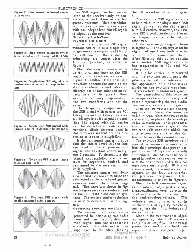
Fi� 2. Sin8le-tone, balanced modu· This SSB signal can be demodu· the SSB waveform shown in figure Ialor output. lated at the receiver only by con· 6.
Fi�re 3. Sin8le-tone balanced modu· lator output alter filterin8 out the LSB.
Fipe 4. Single-tone SSB &i15Jial with carrier-<:arrler equal in amplitude to lone.
Figure 5. Single-tone SSB sl pal with carrler-<:arrier 10 decibels below tone.
Fi8ure 6. Two-tone SSB sipal-tones of equal amplitude.
Fipe 7. Two-tone SSB signal with small reinserted pilot carrier.
28 Dig IZed l
verting it back down in the fre· This two-tone SSB signal i s seen quency spectrum. This demodulat· to be similar to the single-tone DSB ing is done by mixing the signal signal as well as the SSB signal with an independent 300-kilocycle with full carrier. However, the two· IF signal at the receiver. tone SSB signal contains a different Generating Sincle·Tone two frequencies than either of the Waveform With Carrier other two.
From the single-tone SSB signal In the two·tone SSB signal shown without carrier, it is a simple step in figure 6, 1· and 2-kilocycle audio to generate the single-tone SSB sig· signals of equal amplitude are in· nal with carrier. This is done by jected into the balanced modulator. reinserting the carrier after the After filtering, this action results filtering operation, as shown in in a two·tone SSB signal contain· figure 1. ing frequencies of 301 and 302
When the carrier reinserted is kilocycles. of the same amplitude as the SSB If a pilot carrier is reinserted signal, the waveform s h o w n in with the two·tone test signal, the figure 4 results. Note that this pilot carrier will be indicated by wavefr>rm appears the same as the the appearance of a s i n e-wa v e double-sideband signal obtained ripple on the two·tone waveform. directly out of the balanced modu- This waveform is shown in figure 7. lator, as shown in figure 2. HQw· The generation of this two·tone ever, the frequency components of envelope can be shown clearly with the two waveforms a r e not the vectors representing the two audio· same. frequencies, as shown in figure 8.
The frequency components of When the two vectors are exactly the SSB signal with carrier are 301 opposite in phase, the envelope kilocycles and 300 kilocycles when value is zero. When the two vectors a 1-kilocycle audio signal is used. are exactly in phase, the envelope The SSB signal with full carrier value is maximum. This generates can be demodulated with a con- the half sine·wave shape of the ventional diode detector used in two-tone SSB envelope which has AM receivers without serious dis- a repetition rate equal to the dif· tortion or loss of intelligibility. ference between the two audio tones.
If the reinsened carrier is such The two-tone SSB envelope i s of that the carrier level is less than special importance because i t is the level of the single-tone SSB from this envelope that power out· signal, the waveform shown in fig- put from an SSB system is usually ure 5 results. To demodulate the determined. An SSB transmitter is signal successfully, the carrier rated in peak-envelope-power output must be separated, exalted, and with the power measured with a two reinsened in the receiver, or lo- equal-tone test signal. With such cally supplied. a test signal, the actual watts dis·
The separate carrier amplifica· sipated in the load are one-hall tion should be enough to raise the the peak-envelope-power. This reinsened carrier to a level greater measurement is shown in figure 8. than the level of the sideband sig· When the half sine·wave signal nal. The waveform shown in fig· is fed into a load, a peak-reading, ure 5 represents the waveform used r.m.s.·calibrated vtvm across the in the SSB with pilot carrier sys- load indicates the r.m.s. value of terns. The exalted carrier technique the peak-envelope-voltage. This is used to demodulate such a sig· voltmeter reading is equal t o the nal. in-phase sum of e1 + e2, where e 1 Generating Two-Tone Waveform and e2 are the r.m.s. voltages of
The two-tone SSB waveform is the two tones. generated by combining two audio Since in the two-tone test signal tones and then injecting this two- e1 equals e2, the PEP equals tone signal into the b a 1 a n c e d (2e 1)2/ R or (2e2)2R. The average modulator. One sideband is then power dissipated in the load must suppressed by the filter, leaving equal the sum of the power repre·
,11-UNIHRliTY OF CALIFORNIA BuShips Journal
â� ELECTRONICS-
sented by each tone, ej2/R +
e2VR, 4ei2R or 4e22/R.
Therefore, with a two equal-tone
SSB test signal, the average power
dissipated in the load is equal to
'j of the PEP, and the power in
each tone is equal to \ of the PEP.
Peak-envelope-power can be de-
termined from the relationship PEP
= V2Ttvm/R; the average power
can be determined from the rela-
tionship Parage 7 V2 V2ytTm/R.
This relationship is true only
when the vtvm used is a peak-read-
ing, r.m.s. -calibrated voltmeter.
Similar measurements can be made
using an a.c. ammeter in series
with the load instead of the vtvm
across the load.
The above analysis can be car-
ried further to show that with a
three equal-tone SSB test signal,
the power in each tone is % of the
PEP, and the average power dissi-
pated in the load is % the PEP.
These relationships are true only
if there is no distortion of the SSB
envelope, but since distortion is
usually small, its effects are
usually neglected.
Generating Square Waveform
Transmitting an audio square
wave at a radiofrequency imposes
severe requirements on any trans-
mitting system. This is true be-
cause the square wave is composed
of an infinite number of odd-order
harmonics of the fundamental fre-
quency of the square wave.
Therefore, to transmit such a
signal without distortion requires
an infinite bandwidth, an infinite
spectrum. This requirement, of
course, cannot be met because
tuned circuits will not pass an in-
finite bandwidth.
The idealized SSB square wave,
when all frequency components are
present, shown in figure 9, indi-
cates that the SSB signal requires
infinite amplitude as well as in-
finite bandwidth. This condition
occurs because the harmonically
related SSB components will add
vectorally to infinity when the
modulating signal switches from
maximum positive to maximum nega-
tive and vice versa.
This infinite amplitude is not
present in an AM envelope, because
the AM envelope contains both
sidebands with the frequency com-
� e,
"*e,
LOAD
TWO TONE SSB SIGNAL
VTVM
vtvm
(el + e2>'
with ei and e2 in phase and rms values
2
4e* /R or 4e* /R,
pep = Vv"tvm/R|oad
where e-| = e2
= e? /R + e?/R = 2e? /R or 2e\/R
average 1 2
Therefore: (1) PEP
^vtvm
1
/R
(2) p = J/2 PEP
v ' average
V Ptonelor Ptone2= 1/4 PEP
Figure 8. Power measurements from two-tone SSB test signal.
ponents in one sideband counter-
rotating vectorally from the fre-
quency components in the other
sideband. The result then, when
the resultant amplitude of one
sideband is plus infinity, is that
the resultant amplitude of the other
sideband is minus infinity, which
produces a net amplitude of zero.
The significance of the SSB
square wave lies in its relationship
with conventional clipping tech-
niques used to limit the modulation
level.
Figure 10 shows the SSB envelope
that results from severely clipping
a 300 c.p.s. sine wave. The clip-
ping level is such that the modu-
lating signal is essentially a square
wave.
In generating the SSB envelope
from the modulating signal, all
harmonics above the ninth are re-
moved by the highly selective SSB
filter. Figure 9 shows that speech
clipping, as used in AM, is of no
practical value in an SSB transmitter
because the SSB envelope is so
different from the audio envelope.
In an SSB transmitter, automatic
load control, rather than clipping,
is used to prevent overdriving the
power amplifier by holding down
the modulation level. It is possible
to use a significant amount of clip-
ping in an SSB transmitter if the
May 1958
29
sented by each t o n e, e12/R + e22/R, 4e12R or 4e22/R.
Therefore, with a two equal-tone SSB test signal, the average power dissipated in the load is equal to 12 of the PEP, and the power in each tone is equal to�;. of the PEP. Peak-envelope-power can be determined from the relationship PEP = Y2vtvm1R; the average power can be determined from the rela-. h. P 1. z I tlons tp average = ,; V vtvm R.
This relationship is true only when the vtvm used is a peak-reading, r. m. s.-calibrated voltmeter. Similar measurements can be made using an a.c. ammeter in series with the load instead of the vtvm across the load.
The above analysis can be carried further to show that with a tiuee equal-tone SSB test signal, the power in each tone is � of the PEP, and the average power dissi;ated in the load is 1,� the PEP. These relationships are true only if there is no distortion of the SSB envelope, but since distortion is usually small, its e f f e c t s are 1sually neglected. Generating Square Waveform
Transmitting an audio square •·ave at a radiofrequency imposes seYere requirements on any trans::�itting system. This is true becat:se the square wave is composed 'lf an infinite number of odd-order :;armonics of the fundamental freJuency of the square wave.
Therefore, to transmit such a signal without distortion requires m infinite bandwidth, an infinite S?ectrum. This requirement, of course, c a n n o t be met because tuned circuits will not pass an infinite bandwidth.
The idealized SSB square wave, •·h en all frequency components are ?resent, shown in figure 9, indi:ates that the SSB signal requires mfinite amplitude as well as infinite bandwidth. This condition occurs because the harmonically related SSB components will ad d •·ectorally to i nfi n i t y when the -nodulating signal switches from "lJ.ximum positive to maximum negati·•e and vice versa.
This infinite amplitude is not ;-·resent in an A\t envelope, because :�e A\f envelope contains both sidebands with the frequency com-
'Jay 1958
ELECTRONICS
ez el
ez 4 ez ez
.. el et et et ez
VTVM
TWO TONE SSB SIGNAL
vvtvm (e1 + e2), with e1 and e2 2
in phase and rms values
PEP
P average
Vvtvm /Rioad -where e 1 = e 2
2 2 4e 1 /R or 4e2 /R,
2 2 2e2 /R 2e� /R - e1 /R + e2/R - or -- 1
Therefore: PEP 2 ( 1) -
�tvm /R -
(2) Paver age - l/2 PEP -
(3) p p - 1/-' PEP tone 1 or tone 2
Figure 8. Power measurements from two-tone SSil test si�al.
ponents in one sideband counter- lacing signal is essentially a square rotating vectorally from the fre- wave. quency components in the other In generating the SSB envelope sideband. The result then, when from the modulating signal, all the resultam a m p I i t u d e of one harmonics above the ninth are reside band is plus infiniry, is that moved by the highly selective SSB the resultant amplitude of the other filter. Figure 9 shows that speech sideband is minus infinity, which clipping, as used in AM, is of no produces a net amplitude of zero. practical value in an SSB transmitter
The significance of the SSB because the SSB envelope is so square wave lies in its relationship different from the audio envelope. with conventional clipping tech- In an SSB transmitter, automatic niques used to limit the modulation load control, rather than clipping,
level. is used to prevent overdriving the
Figure 10 shows the SSB envelope power amplifier by holding down that results from severely clipping the modulation level. It is possible a 300 c.p.s. sine wave. The clip- to use a sign ificant amount of clipping level is such that the mod ·rigi 1i &"rtJ an SSB transmitter if the
UNIVERSITY OF CALIFORNIA 29
�ELECTRONICS-
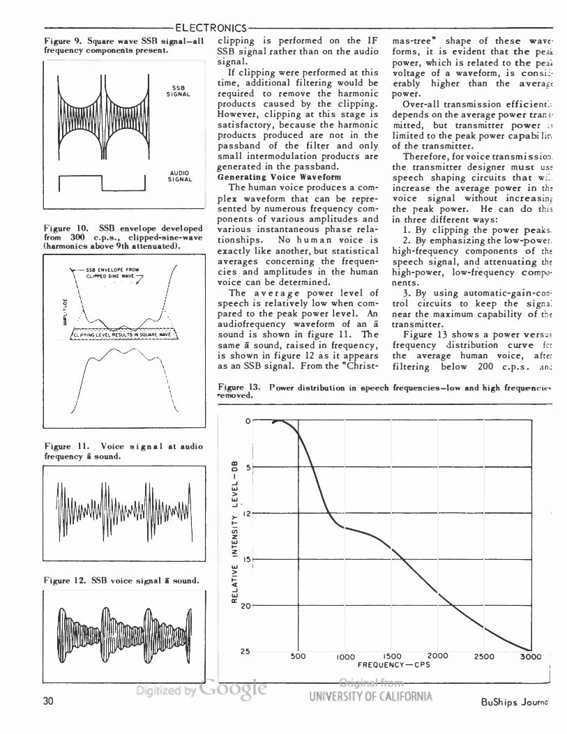
Figure 9. Square wave SSB signal�all
frequency components present.
SSB
SIGNAL
1
AUDIO
SIGNAL
Figure 10. SSB envelope developed
from 300 c.p.s., clipped-sine-wave
(harmonics above 9th attenuated).
Figure 11. Voice signal at audio
frequency a sound.
Figure 12. SSB voice signal a sound.
a
clipping is performed on the IF
SSB signal rather than on the audio
signal.
If clipping were performed at this
time, additional filtering would be
required to remove the harmonic
products caused by the clipping.
However, clipping at this stage is
satisfactory, because the harmonic
products produced are not in the
passband of the filter and only
small intermodulation products are
generated in the passband.
Generating Voice Waveform
The human voice produces a com-
plex waveform that can be repre-
sented by numerous frequency com-
ponents of various amplitudes and
various instantaneous phase rela-
tionships. No human voice is
exactly like another, but statistical
averages concerning the frequen-
cies and amplitudes in the human
voice can be determined.
The average power level of
speech is relatively low when com-
pared to the peak power level. An
audiofrequency waveform of an a
sound is shown in figure 11. The
same a sound, raised in frequency,
is shown in figure 12 as it appears
as an SSB signal. From the "Christ-
mas-tree" shape of these wave-
forms, it is evident that the peak
power, which is related to the peak
voltage of a waveform, is consid-
erably higher than the average
power.
Over-all transmission efficiently
depends on the average power trans-
mitted, but transmitter power is
limited to the peak power capability
of the transmitter.
Therefore, for voice transmission,
the transmitter designer must use
speech shaping circuits that will
increase the average power in the
voice signal without increasing
the peak power. He can do this
in three different ways:
1. By clipping the power peaks.
2. By emphasizing the low-power,
high-frequency components of the
speech signal, and attenuating the
high-power, low-frequency compo-
nents.
3. By using automatic-gain-con-
trol circuits to keep the signal
near the maximum capability of the
transmitter.
Figure 13 shows a power versus
frequency distribution curve for
the average human voice, after
filtering below 200 c.p.s. and
Figure 13.
*e moved.
Power distribution in speech frequencies�low and high frequencies
CD
o
I
-J
>
-J '
10
z
UJ
15
<
_l
20
25
P *w
500
1000 1500 2000
FREQUENCY �CPS
2500
300C
30
BuShips Journal
-----------------ELECTRONICS----------------------------------------figure 9. Square wave SSR signal-all frequency components present.
sse
SIGNAL
AUDIO
SIGNAL
figure 10. SSD envelope developed from 300 c.p.s., clipped•sine•wave (harmonics above 9th attenuated).
� SSB ENVELOPE FROII \ CLIPPED S.INE .WAVE.7
figure 11. Voice s i g n a l at audio frequency i sound.
Figure 12. SSD voice signal a sound.
30 Dig
clipping is performed on the IF SSB signal rather than on the audio signal.
If clipping were performed at this time, additional filtering would be required to remove the harmonic products caused by the clipping. However, clipping at this stage is satisfactory, because the harmonic products produced are not in the passband of the filter and only small intermodulation products are generated in the passband. Generating Voice Waveform
The human voice produces a complex waveform that can be represented by numerous frequency components of various amplitudes and various instantaneous phase re Iationships. No h u m a n voice is exactly like another, but statistical averages concerning the frequencies and amplitudes in the human voice can be determined.
The a v e r a g e power level of speech is relatively low when compared to the peak power level. An audiofrequency waveform of an a sound is shown in figure 11. The same a sound, raised in frequency, is shown in figure 12 as it appears as an SSB signal. From the "Christ-
mas-tree" shape of these wan· forms, it is evident that the peak power, which is related to the peai voltage of a waveform, is consi�· erably higher than the a veragt power.
Over-all transmission efficienr>. depends on the average power trans· mitted, but transmitter power ;; limited to the peak power capabi lir. of the transmitter.
Therefore, for voice transmissio:J. the transmitter designer mu st use
speech shaping circuits that w::. increase the average power in th� voice signal without increasing the peak power. He can do this in three different ways:
1. By clipping the power peaks. 2. By emphasizing the low-power.
high-frequency components of the speech signal, and attenuating the high-power, low-frequency compo· nents.
3. By using automatic-gain-con· trol circuits to keep the signa: near the maximum capability of the transmitter.
Figure 13 shows a power vers:�" frequency distribution curve frr the average human voice, aftei filtering below 200 c.p.s. an�
figure 13. Power distribution in speech frequencies-low and high frequencie• .. ernoved.
0
m 5 0
I .J w > w .J'
>-12
......
Ill z w ..... z
15 w >
i= ot .J w a:
20
25
... -,
1\
500
\ '
"' '
� "'-
1000 1500 2000 FREQUENCY- CPS
UNIVERSITY 0 F CALl FORN lA
� �
2500 3000
BuSh ips Journo:
-ELECTRONICS-
above 3000 c.p.s. This curve
shows that the high-power compo-
nents of speech are concentrated
in the low frequencies.
Fortunately, it is the low-fre-
quency components of speech that
contribute little to intelligibility
since these frequencies are con-
centrated in the vowel sounds.
The low frequencies, therefore,
may be attenuated without undue
loss of intelligibility of the speech.
The low-power, high-frequency
components present in a voice sig-
nal can be pre-emphasized to in-
crease the average power level of
the signal. Since it is the high-
frequency components that pre-
dominate in the consonant sounds,
some emphasis of high frequencies
will improve intelligibility.
However, to emphasize the high
frequencies enough to raise the
average power level significantly
would require compatible de-em-
phasis at the receiver to prevent
loss of fidelity.
Clipping of power peaks results
in flattening the waveform at the
clipping level; and with severe
clipping, the voice signal becomes
a series of square waves.
Since an SSB square wave en-
velope requires infinite amplitude
as well as infinite bandwidth, the
audio signal must be clipped with
discretion.
In the SSB transmitter, automatic
load control is used to control the
average power level input, rather
than clipping, to prevent overdriv-
ing the power amplifier. Clipping
then is used only to remove the
occasional power peaks.
Speech-processing methods are
being reinvestigated in relation to
SSB transmission to determine the
most suitable method or combina-
tion of methods. At present, sev-
eral circuits are used in SSB trans-
mitters which do some speech
processing, although the primary
purpose of most of them is to proc-
ess the input signal to prevent
overdriving the power amplifier.
These circuits include:
� Automatic-load-control to main-
tain signal peaks at the maximum
rating of the power amplifier.
� Speech compression, with some
clipping, to maintain a constant
signal level to the single-sideband
generator.
� Highly-selective filters used
in filter-type SSB exciters to at-
tenuate some of the high-power,
low-frequency components of the
voice signal.
There are also several speech
processing circuits under investi-
gation which, if effective and prac-
tical, will be used to improve the
efficiency of voice transmission.
These circuits include:
� Increased audio clipping with
additional filtering to remove the
harmonics generated.
� Reduction of the power level
of frequencies below 1000 c.p.s.
by shaping the audio amplifier
characteristics for low-frequency
roll-off.
� Use of speech clipping at an
IF level where the generated har-
monics can be more easily filtered.
More information on the input
signal processing circuits will be
included in a later article in this
series. The next article is on
mechanical filters.
TIMELY CONSIDERATION OF INTERFERENCE CONTROL
By C. R. Billheimer
Interference Control Section
Bureau of Ships
If naval communications and
electronic control devices are
to operate satisfactorily, elec-
tronic, electrical, and mechanical
equipment and devices in the
area must not produce interfer-
ence.
Also, interference must be ef-
fectively controlled if the mili-
tary and civil life of the United
States is to profit from the many
proposed new advantages in the
conveyance of intelligence and
automation.
Experience shows that interfer-
ence is, in most cases, indicative
of incomplete equipment design or
mistakes on the production line.
Suppression Inadequate
Whenever interference control is
considered as a "suppression meas-
ure* to be handled at a time past
the engineering stage, increased
costs and relatively unsatisfactory
results usually ensue. Then re-
liability features are often com-
promised.
If proper design features are in-
corporated in the initial develop-
ment stages and appropriate con-
trol measures are used in produc-
tion, interference need not be a
serious problem, nor does its con-
trol need to be costly.
The Bureau of Ships has often
found equipments, supposedly ready
for shipment by the manufacturer,
to be deficient and thereby to have
high interference characteristics.
Embarrassing delays are usually
experienced while corrective meas-
ures are worked out.
In practically all such cases,
the delayed corrective measures
are only partially satisfactory; and
while incorporating the measures
in the equipment, the usual rea-
sons for interference are found to
be true: Incomplete design and
mistakes in production.
Responsibility
A naval contractor who procures
equipment components outside his
own factory should require them to
be interference free. He should
screen and check these components
prior to acceptance to determine
that interference requirements are
met.
Manufacturers who do not have,
in their own plants, the facilities
essential to guide design, control
production, and demonstrate to
naval inspectors that their equip-
ment complies with the contract
requirements concerning interfer-
ence, should retain the services of
a consulting laboratory.
If a naval contractor is uncertain
about interference requirements in
a contract, or of the proper steps
to be taken relative to furnishing
interference free equipment, he
should consult with the naval in-
spection office or the cognizant
bureau early in the design stage of
the equipment.
May 1958
31
-------------------------------------------ELECTRONICS ------------------
above 3000 c.p.s. This curve shows that the high-power components of speech are concentrated in the low frequencies.
Fortunately, it is the low-frequency components of speech that contribute little to intelligibility since these frequencies are concentrated in the vowel sounds. The low frequencies, therefore, may be attenuated without undue loss of intelligibility of the speech.
The low-power, high-frequency components present in a voice signal c an be pre-emphasized to increase the average power level of the signal. Since it is the highfrequency components that predominate in the consonant sounds, some emphasis of high frequencies will improve intelligibility.
However, to emphasize the high frequencies enough to raise the average power level significantly would require compatible de-emphasis at the receiver to prevent loss of fidelity.
Clipping of power peaks results in flattening the waveform at the clipping level; and with severe
clipping, the voice signal becomes a series of square waves.
Since an SSB square wave envelope requires infinite amplitude as well as infinite bandwidth, the audio signal must be clipped with discretion.
In the SSB transmitter, automatic load control is used to control the average power level input, rather than clipping, to prevent overdriving the power amplifier. Clipping then is used only to remove the occasional power peaks.
Speech-processing methods are being reinvestigated in relation to SSB transmission to determine the most suitable method or combination of methods. At present, several circuits are used in SSB transmitters which do some s p e e c h processing, although the primary purpose of most of them is to process the input signal to prevent overdriving the power amplifier. These circuits include:
• Automatic-load-control to maintain signal peaks at the maximum rating of the power amplifier.
• Speech compression, with some
clipping, to maintain a constant signal level to the single-sideband generator.
• Highly-selective filters used in filter-type SSB exciters to attenuate some of the high-power, low-frequency components of the voice signal.
There are also several speech processing circuits under investigation which, if effective and practical, will be used to improve the efficiency of voice transmission. These circuits include:
• Increased audio clipping with additional filtering to remove the harmonics generated.
• Reduction of the power !eve 1 of frequencies below 1000 c.p.s. by shaping the audio amplifier characteristics for low-frequency roll-off.
• Use of speech clipping at an IF level where the generated harmonics can be more easily filtered.
More information on the input signal processing circuits will be included in a later article in this series. The next article is on mechanical filters.
TIMELY CONSIDERATION OF INTERFERENCE CONTROL
By C. R. Billheimer Interference Control Section
Bureau of Ships
If naval communications and electronic control d e v i c e s are co operate satisfactorily, eleccronic, electrical, and mechanical equipment and d e v i c e s in the area mu s t not produce interference .
.'\lso, interference must be effectively controlled if the military and civil life of the United Scates is to profit from the many proposed new advantages in the conveyance of intelligence and automation.
Experience shows that interference is, in most cases, indicative of incomplete equipment design or mista.lces on the production line. Suppression Inadequate
Thenever interference control is considered as a "suppression measure• to be handled at a time past the engineering stage, increased
f.lay 1958 D1g 1ze
costs and relatively unsatisfactory Responsibility results usually ensue. Then re- A naval contractor who procures liability features are often com- equipment components outside his promised. own factory should require them to
If proper design features are in- be interference free. He should corporated in the initial develop- screen and check these components ment stages and appropriate con- prior to acceptance to determine trol measures are used in produc- that interference requirements are cion, interference need not be a met. serious problem, nor does its con- Manufacturers who do not have, trol need to be costly. in their own plants, the facilities
The Bureau of Ships has often essential to guide design, control found equipments, supposedly ready production, and demonstrate to for shipment by the manufacturer, naval inspectors that their equipto be deficient and thereby to have ment complies with the contract high interference characteristics. requirements concerning interferEmbarrassing delays are usually ence, should retain the services of experienced while corrective meas- a consulting laboratory. ures are worked out. If a naval contractor is uncertain
In practically all such cases, about interference requirements in the delayed corrective measures a contract, or of the proper steps are only partially satisfactory; and to be taken relative to furnishing while incorporating the measures interference f r e e equipment, he in the equipment, the usual rea- should consult with the naval insons for interference are found to spection office or the cognizant be true: Incomplete design and bureau early in the design stage of mistakes in production. the equipment.
Original from 0 UNIVERSITY OF CALIFORNIA 31