Embed Size (px)
Citation preview
SRX1500 Services Gateway Hardware Guide
Modified: 2018-12-18
Copyright © 2018, Juniper Networks, Inc.

Juniper Networks, Inc.1133 InnovationWaySunnyvale, California 94089USA408-745-2000www.juniper.net
Juniper Networks, the Juniper Networks logo, Juniper, and Junos are registered trademarks of Juniper Networks, Inc. in the United Statesand other countries. All other trademarks, service marks, registeredmarks, or registered service marks are the property of their respectiveowners.
Juniper Networks assumes no responsibility for any inaccuracies in this document. Juniper Networks reserves the right to change, modify,transfer, or otherwise revise this publication without notice.
SRX1500 Services Gateway Hardware GuideCopyright © 2018 Juniper Networks, Inc. All rights reserved.
The information in this document is current as of the date on the title page.
YEAR 2000 NOTICE
Juniper Networks hardware and software products are Year 2000 compliant. Junos OS has no known time-related limitations through theyear 2038. However, the NTP application is known to have some difficulty in the year 2036.
ENDUSER LICENSE AGREEMENT
The Juniper Networks product that is the subject of this technical documentation consists of (or is intended for use with) Juniper Networkssoftware. Use of such software is subject to the terms and conditions of the End User License Agreement (“EULA”) posted athttps://support.juniper.net/support/eula/. By downloading, installing or using such software, you agree to the terms and conditions ofthat EULA.
Copyright © 2018, Juniper Networks, Inc.ii

Table of Contents
About the Documentation . . . . . . . . . . . . . . . . . . . . . . . . . . . . . . . . . . . . . . . . . . . . xi
Documentation and Release Notes . . . . . . . . . . . . . . . . . . . . . . . . . . . . . . . . . . xi
Documentation Conventions . . . . . . . . . . . . . . . . . . . . . . . . . . . . . . . . . . . . . . . xi
Documentation Feedback . . . . . . . . . . . . . . . . . . . . . . . . . . . . . . . . . . . . . . . . xiii
Requesting Technical Support . . . . . . . . . . . . . . . . . . . . . . . . . . . . . . . . . . . . . xiv
Self-Help Online Tools and Resources . . . . . . . . . . . . . . . . . . . . . . . . . . . xiv
Opening a Case with JTAC . . . . . . . . . . . . . . . . . . . . . . . . . . . . . . . . . . . . . xv
Chapter 1 Overview . . . . . . . . . . . . . . . . . . . . . . . . . . . . . . . . . . . . . . . . . . . . . . . . . . . . . . . . . 17
SRX1500 Services Gateway Overview . . . . . . . . . . . . . . . . . . . . . . . . . . . . . . . . . . . 17
SRX1500 Services Gateway Overview . . . . . . . . . . . . . . . . . . . . . . . . . . . . . . . 17
SRX1500 Services Gateway Field Replaceable Units Overview . . . . . . . . . . . 18
SRX1500 Chassis . . . . . . . . . . . . . . . . . . . . . . . . . . . . . . . . . . . . . . . . . . . . . . . . . . . 18
SRX1500 Services Gateway Chassis Overview . . . . . . . . . . . . . . . . . . . . . . . . 18
SRX1500 Services Gateway Front Panel . . . . . . . . . . . . . . . . . . . . . . . . . . . . . 19
SRX1500 Services Gateway Back Panel . . . . . . . . . . . . . . . . . . . . . . . . . . . . . 22
SRX1500 Cooling System . . . . . . . . . . . . . . . . . . . . . . . . . . . . . . . . . . . . . . . . . . . . 23
SRX1500 Power System . . . . . . . . . . . . . . . . . . . . . . . . . . . . . . . . . . . . . . . . . . . . . 23
SRX1500 Services Gateway Power Supply . . . . . . . . . . . . . . . . . . . . . . . . . . . 23
SRX1500 Services Gateway Supported AC Power Cords . . . . . . . . . . . . . . . . 25
SRX1500 Services Gateway AC Power Supply Electrical Specifications . . . . 26
SRX1500 Services Gateway DC Power Supply Electrical Specifications . . . . 26
SRX1500 Services Gateway DC Power Cable Specifications . . . . . . . . . . . . . 26
Chapter 2 Site Planning, Preparation, and Specifications . . . . . . . . . . . . . . . . . . . . . . . . 29
Site Preparation Checklist for the SRX1500 Services Gateway . . . . . . . . . . . . . . . 29
SRX1500 Site Guidelines and Requirements . . . . . . . . . . . . . . . . . . . . . . . . . . . . . . 31
SRX1500 Services Gateway General Site Installation Guidelines . . . . . . . . . . 31
SRX1500 Services Gateway Environmental Specifications . . . . . . . . . . . . . . . 31
SRX1500 Services Gateway Electrical Wiring Guidelines . . . . . . . . . . . . . . . . 32
SRX1500 Services Gateway Grounding Specifications . . . . . . . . . . . . . . . . . . 33
SRX1500 Services Gateway Physical Specifications . . . . . . . . . . . . . . . . . . . 34
SRX1500 Services Gateway Clearance Requirements for Airflow and
Hardware Maintenance . . . . . . . . . . . . . . . . . . . . . . . . . . . . . . . . . . . . . . . 34
Rack Requirements . . . . . . . . . . . . . . . . . . . . . . . . . . . . . . . . . . . . . . . . . . . . . . 35
Cabinet Requirements . . . . . . . . . . . . . . . . . . . . . . . . . . . . . . . . . . . . . . . . . . . 36
SRX1500 Transceiver Specifications and Pinouts . . . . . . . . . . . . . . . . . . . . . . . . . 37
SRX1500 Transceiver Support . . . . . . . . . . . . . . . . . . . . . . . . . . . . . . . . . . . . . 37
RJ-45 Connector Pinouts for the SRX1500 Services Gateway Ethernet
Port . . . . . . . . . . . . . . . . . . . . . . . . . . . . . . . . . . . . . . . . . . . . . . . . . . . . . . . 37
iiiCopyright © 2018, Juniper Networks, Inc.

RJ-45 Connector Pinouts for the SRX1500 Services Gateway Console
Port . . . . . . . . . . . . . . . . . . . . . . . . . . . . . . . . . . . . . . . . . . . . . . . . . . . . . . . 38
Mini-USB Connector Pinouts for the SRX1500 Services Gateway Console
Port . . . . . . . . . . . . . . . . . . . . . . . . . . . . . . . . . . . . . . . . . . . . . . . . . . . . . . . 38
Chapter 3 Initial Installation and Configuration . . . . . . . . . . . . . . . . . . . . . . . . . . . . . . . . . 41
SRX1500 Services Gateway Installation Overview . . . . . . . . . . . . . . . . . . . . . . . . . 41
Unpacking and Mounting the SRX1500 . . . . . . . . . . . . . . . . . . . . . . . . . . . . . . . . . 42
Unpacking the SRX1500 Services Gateway . . . . . . . . . . . . . . . . . . . . . . . . . . 42
Verifying Parts Received with the SRX1500 Services Gateway . . . . . . . . . . . 42
Preparing the SRX1500 Services Gateway for Rack-Mount Installation . . . . 43
Installing the SRX1500 Services Gateway in a Rack . . . . . . . . . . . . . . . . . . . . 44
Connecting the SRX1500 to Power . . . . . . . . . . . . . . . . . . . . . . . . . . . . . . . . . . . . . 45
Required Tools and Parts for Grounding the SRX1500 Services Gateway . . . 45
Connecting the SRX1500 Services Gateway Grounding Cable . . . . . . . . . . . 46
Installing an AC Power Supply on the SRX1500 Services Gateway . . . . . . . . 47
Connecting the SRX1500 Services Gateway to an AC Power Supply . . . . . . 48
Installing a DC Power Supply on the SRX1500 Services Gateway . . . . . . . . . 49
Connecting the SRX1500 Services Gateway to a DC Power Supply . . . . . . . . 52
Powering On the SRX1500 Services Gateway . . . . . . . . . . . . . . . . . . . . . . . . . 53
Powering Off the SRX1500 Services Gateway . . . . . . . . . . . . . . . . . . . . . . . . 54
Connecting the SRX1500 to External Devices . . . . . . . . . . . . . . . . . . . . . . . . . . . . 54
Required Tools and Parts for Connecting the SRX1500 Services
Gateway . . . . . . . . . . . . . . . . . . . . . . . . . . . . . . . . . . . . . . . . . . . . . . . . . . . 55
Connecting the SRX1500 Services Gateway to a Network for Out-of-Band
Management . . . . . . . . . . . . . . . . . . . . . . . . . . . . . . . . . . . . . . . . . . . . . . . 55
Connecting the SRX1500 Services Gateway to a Management Console . . . . 55
Configuring Junos OS on the SRX1500 . . . . . . . . . . . . . . . . . . . . . . . . . . . . . . . . . . 56
SRX1500 Services Gateway Software Configuration Overview . . . . . . . . . . . 57
Understanding SRX1500 Services Gateway Factory-Default Settings . . . . . . 57
Viewing SRX1500 Services Gateway Factory-Default Settings . . . . . . . . . . . 57
Accessing J-Web on the SRX1500 Services Gateway . . . . . . . . . . . . . . . . . . . 58
Configuring the SRX1500 Services Gateway Using J-Web . . . . . . . . . . . . . . . 58
Configuring Root Authentication and the Management Interface from
the CLI . . . . . . . . . . . . . . . . . . . . . . . . . . . . . . . . . . . . . . . . . . . . . . . . . 58
Configuring Interfaces, Zones, and Policies with J-Web . . . . . . . . . . . . . . 59
Accessing the CLI on the SRX1500 Services Gateway . . . . . . . . . . . . . . . . . . 62
Connecting to the SRX1500 Services Gateway from the CLI Remotely . . . . . 63
Configuring the SRX1500 Services Gateway Using the CLI . . . . . . . . . . . . . . 63
Copyright © 2018, Juniper Networks, Inc.iv
SRX1500 Services Gateway Hardware Guide

Chapter 4 Maintaining Components . . . . . . . . . . . . . . . . . . . . . . . . . . . . . . . . . . . . . . . . . . 69
Maintaining the SRX1500 Components . . . . . . . . . . . . . . . . . . . . . . . . . . . . . . . . . 69
Required Tools and Parts for Maintaining the SRX1500 Services
Gateway . . . . . . . . . . . . . . . . . . . . . . . . . . . . . . . . . . . . . . . . . . . . . . . . . . . 69
Routine Maintenance Procedures for the SRX1500 Services Gateway . . . . . 69
Maintaining the SRX1500 Power System . . . . . . . . . . . . . . . . . . . . . . . . . . . . . . . . 69
Maintaining the SRX1500 Services Gateway Power Supply . . . . . . . . . . . . . . 70
Required Tools and Parts for Replacing the SRX1500 Services Gateway
Components . . . . . . . . . . . . . . . . . . . . . . . . . . . . . . . . . . . . . . . . . . . . . . . 70
Replacing an AC Power Supply on the SRX1500 Services Gateway . . . . . . . 70
Disconnecting an AC Power Cord from the SRX1500 Services
Gateway . . . . . . . . . . . . . . . . . . . . . . . . . . . . . . . . . . . . . . . . . . . . . . . 70
Removing an AC Power Supply from the SRX1500 Services
Gateway . . . . . . . . . . . . . . . . . . . . . . . . . . . . . . . . . . . . . . . . . . . . . . . . 71
Replacing a DC Power Supply on the SRX1500 Services Gateway . . . . . . . . . 72
Removing a DC Power Supply Cable from the SRX1500 Services
Gateway . . . . . . . . . . . . . . . . . . . . . . . . . . . . . . . . . . . . . . . . . . . . . . . 72
Removing a DC Power Supply on the SRX1500 Services Gateway . . . . . 72
Chapter 5 Troubleshooting Hardware . . . . . . . . . . . . . . . . . . . . . . . . . . . . . . . . . . . . . . . . . 75
Troubleshooting the SRX1500 . . . . . . . . . . . . . . . . . . . . . . . . . . . . . . . . . . . . . . . . . 75
Troubleshooting Resources for the SRX1500 Services Gateway
Overview . . . . . . . . . . . . . . . . . . . . . . . . . . . . . . . . . . . . . . . . . . . . . . . . . . . 75
Troubleshooting Chassis and Interface AlarmMessages on the SRX1500
Services Gateway . . . . . . . . . . . . . . . . . . . . . . . . . . . . . . . . . . . . . . . . . . . . 75
Troubleshooting the Power System on the SRX1500 Services Gateway . . . . 77
Using the RESET CONFIG Button on the SRX1500 Services Gateway . . . . . . 78
Changing the RESET CONFIG Button Behavior on the SRX1500 Services
Gateway . . . . . . . . . . . . . . . . . . . . . . . . . . . . . . . . . . . . . . . . . . . . . . . . . . . 79
Chapter 6 Contacting Customer Support and Returning the Chassis orComponents . . . . . . . . . . . . . . . . . . . . . . . . . . . . . . . . . . . . . . . . . . . . . . . . . . . . . . 81
Returning the SRX1500 Chassis or Components . . . . . . . . . . . . . . . . . . . . . . . . . . 81
Contacting Customer Support . . . . . . . . . . . . . . . . . . . . . . . . . . . . . . . . . . . . . 81
Returning a SRX1500 Services Gateway Component to Juniper
Networks . . . . . . . . . . . . . . . . . . . . . . . . . . . . . . . . . . . . . . . . . . . . . . . . . . 82
Locating theSRX1500ServicesGatewayChassisSerialNumberandAgency
Labels . . . . . . . . . . . . . . . . . . . . . . . . . . . . . . . . . . . . . . . . . . . . . . . . . . . . . 82
Listing the SRX1500 Services Gateway Component Details with the CLI . . . 82
Required Tools and Parts for Packing the SRX1500 Services Gateway . . . . . 83
Packing the SRX1500 Services Gateway for Shipment . . . . . . . . . . . . . . . . . 84
Packing SRX1500 Services Gateway Components for Shipment . . . . . . . . . 85
Chapter 7 Safety and Compliance Information . . . . . . . . . . . . . . . . . . . . . . . . . . . . . . . . . 87
Definitions of Safety Warning Levels . . . . . . . . . . . . . . . . . . . . . . . . . . . . . . . . . . . . 87
General Safety Guidelines and Warnings . . . . . . . . . . . . . . . . . . . . . . . . . . . . . . . . 89
Restricted Access Warning . . . . . . . . . . . . . . . . . . . . . . . . . . . . . . . . . . . . . . . . . . . 90
Qualified Personnel Warning . . . . . . . . . . . . . . . . . . . . . . . . . . . . . . . . . . . . . . . . . . 91
Prevention of Electrostatic Discharge Damage . . . . . . . . . . . . . . . . . . . . . . . . . . . 92
vCopyright © 2018, Juniper Networks, Inc.
Table of Contents

Fire Safety Requirements . . . . . . . . . . . . . . . . . . . . . . . . . . . . . . . . . . . . . . . . . . . . 94
Fire Suppression . . . . . . . . . . . . . . . . . . . . . . . . . . . . . . . . . . . . . . . . . . . . . . . . 94
Fire Suppression Equipment . . . . . . . . . . . . . . . . . . . . . . . . . . . . . . . . . . . . . . 94
Laser and LED Safety Guidelines andWarnings . . . . . . . . . . . . . . . . . . . . . . . . . . . 95
General Laser Safety Guidelines . . . . . . . . . . . . . . . . . . . . . . . . . . . . . . . . . . . 95
Class 1 Laser Product Warning . . . . . . . . . . . . . . . . . . . . . . . . . . . . . . . . . . . . . 95
Class 1 LED Product Warning . . . . . . . . . . . . . . . . . . . . . . . . . . . . . . . . . . . . . . 96
Laser Beam Warning . . . . . . . . . . . . . . . . . . . . . . . . . . . . . . . . . . . . . . . . . . . . 96
Radiation from Open Port Apertures Warning . . . . . . . . . . . . . . . . . . . . . . . . . . . . 97
Maintenance and Operational Safety Guidelines and Warnings . . . . . . . . . . . . . . 98
Battery Handling Warning . . . . . . . . . . . . . . . . . . . . . . . . . . . . . . . . . . . . . . . . 98
Jewelry Removal Warning . . . . . . . . . . . . . . . . . . . . . . . . . . . . . . . . . . . . . . . . 99
Lightning Activity Warning . . . . . . . . . . . . . . . . . . . . . . . . . . . . . . . . . . . . . . . 100
Operating Temperature Warning . . . . . . . . . . . . . . . . . . . . . . . . . . . . . . . . . . . 101
Product Disposal Warning . . . . . . . . . . . . . . . . . . . . . . . . . . . . . . . . . . . . . . . . 102
Action to Take After an Electrical Accident . . . . . . . . . . . . . . . . . . . . . . . . . . . . . . 103
General Electrical Safety Guidelines and Warnings . . . . . . . . . . . . . . . . . . . . . . . 103
Safety Guidelines and Warnings . . . . . . . . . . . . . . . . . . . . . . . . . . . . . . . . . . . 103
Grounded Equipment Warning . . . . . . . . . . . . . . . . . . . . . . . . . . . . . . . . . . . . 104
Backplane Energy Hazard Warning . . . . . . . . . . . . . . . . . . . . . . . . . . . . . . . . 104
Multiple Power Supplies Disconnection Warning . . . . . . . . . . . . . . . . . . . . . 104
Power Disconnection Warning . . . . . . . . . . . . . . . . . . . . . . . . . . . . . . . . . . . . 105
TN Power Warning . . . . . . . . . . . . . . . . . . . . . . . . . . . . . . . . . . . . . . . . . . . . . 106
Copper Conductors Warning . . . . . . . . . . . . . . . . . . . . . . . . . . . . . . . . . . . . . . 107
AC Power Electrical Safety Guidelines . . . . . . . . . . . . . . . . . . . . . . . . . . . . . . . . . . 107
DC Power Electrical Safety Guidelines . . . . . . . . . . . . . . . . . . . . . . . . . . . . . . . . . 108
DC Power Electrical Safety Guidelines . . . . . . . . . . . . . . . . . . . . . . . . . . . . . . 108
DC Power Disconnection Warning . . . . . . . . . . . . . . . . . . . . . . . . . . . . . . . . . 109
DC Power Grounding Requirements and Warning . . . . . . . . . . . . . . . . . . . . . . 111
DC Power Wiring Sequence Warning . . . . . . . . . . . . . . . . . . . . . . . . . . . . . . . . 112
DC Power Wiring Terminations Warning . . . . . . . . . . . . . . . . . . . . . . . . . . . . . 113
SRX1500 Services Gateway Agency Approvals . . . . . . . . . . . . . . . . . . . . . . . . . . . 114
SRX1500 Services Gateway Acoustic Noise Compliance Statements . . . . . . . . . 115
SRX1500 Services Gateway EMC Requirements . . . . . . . . . . . . . . . . . . . . . . . . . . 116
Canada . . . . . . . . . . . . . . . . . . . . . . . . . . . . . . . . . . . . . . . . . . . . . . . . . . . . . . . 116
European Community . . . . . . . . . . . . . . . . . . . . . . . . . . . . . . . . . . . . . . . . . . . 116
Israel . . . . . . . . . . . . . . . . . . . . . . . . . . . . . . . . . . . . . . . . . . . . . . . . . . . . . . . . . 116
Japan . . . . . . . . . . . . . . . . . . . . . . . . . . . . . . . . . . . . . . . . . . . . . . . . . . . . . . . . . 116
United States . . . . . . . . . . . . . . . . . . . . . . . . . . . . . . . . . . . . . . . . . . . . . . . . . . 116
Copyright © 2018, Juniper Networks, Inc.vi
SRX1500 Services Gateway Hardware Guide

List of Figures
Chapter 1 Overview . . . . . . . . . . . . . . . . . . . . . . . . . . . . . . . . . . . . . . . . . . . . . . . . . . . . . . . . . 17
Figure 1: SRX1500 Services Gateway Front Panel . . . . . . . . . . . . . . . . . . . . . . . . . . 19
Figure 2: SRX1500 Services Gateway Front Panel LEDs . . . . . . . . . . . . . . . . . . . . . 21
Figure 3: SRX1500 Services Gateway Back Panel . . . . . . . . . . . . . . . . . . . . . . . . . . 22
Figure 4: AC Power Supply for the SRX1500 Services Gateway . . . . . . . . . . . . . . . 24
Figure 5: DC Power Supply for the SRX1500 Services Gateway . . . . . . . . . . . . . . . 24
Figure 6: AC Plug Types . . . . . . . . . . . . . . . . . . . . . . . . . . . . . . . . . . . . . . . . . . . . . . 25
Chapter 2 Site Planning, Preparation, and Specifications . . . . . . . . . . . . . . . . . . . . . . . . 29
Figure 7: Airflow Through the Chassis . . . . . . . . . . . . . . . . . . . . . . . . . . . . . . . . . . . 35
Chapter 3 Initial Installation and Configuration . . . . . . . . . . . . . . . . . . . . . . . . . . . . . . . . . 41
Figure 8: Installing the Mounting Brackets on the SRX1500 Services Gateway . . 44
Figure 9: Installing the SRX1500 Services Gateway in a Rack . . . . . . . . . . . . . . . . 45
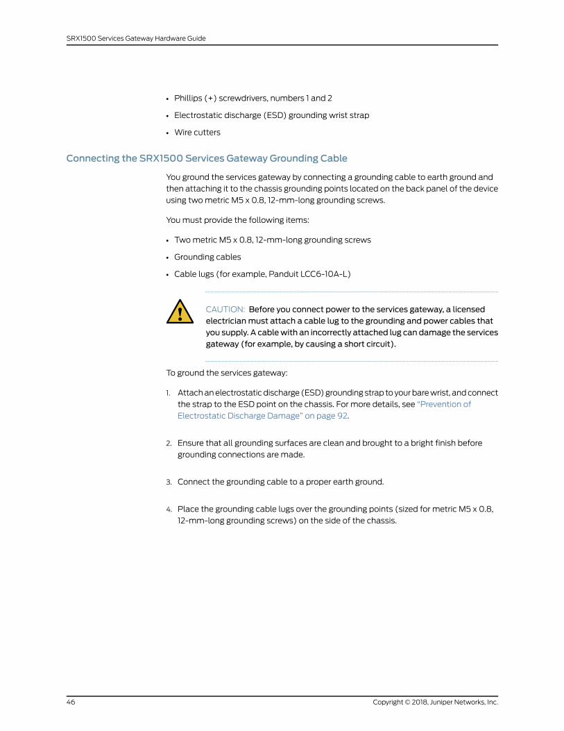
Figure 10: Connecting the Grounding Cable to the SRX1500 Services
Gateway . . . . . . . . . . . . . . . . . . . . . . . . . . . . . . . . . . . . . . . . . . . . . . . . . . . . . . . 47
Figure 11: Installing an AC Power Supply on the SRX1500 Services Gateway . . . . 47
Figure 12: Connecting the AC Power Cord on the SRX1500 Services Gateway . . . 48
Figure 13: Installing a DC Power Supply on an SRX1500 Services Gateway . . . . . 49
Figure 14: Securing the Power Cables . . . . . . . . . . . . . . . . . . . . . . . . . . . . . . . . . . . . 51
Figure 15: Connecting the SRX1500 Services Gateway to a Network for
Out-of-Band Management . . . . . . . . . . . . . . . . . . . . . . . . . . . . . . . . . . . . . . . 55
Figure 16: Connecting the SRX1500 Services Gateway to a Management
Console . . . . . . . . . . . . . . . . . . . . . . . . . . . . . . . . . . . . . . . . . . . . . . . . . . . . . . . 56
Chapter 4 Maintaining Components . . . . . . . . . . . . . . . . . . . . . . . . . . . . . . . . . . . . . . . . . . 69
Figure 17: Removing an AC Power Supply from the SRX1500 Services
Gateway . . . . . . . . . . . . . . . . . . . . . . . . . . . . . . . . . . . . . . . . . . . . . . . . . . . . . . . 71
Figure 18: Removing a DC Power Supply from the SRX1500 Services
Gateway . . . . . . . . . . . . . . . . . . . . . . . . . . . . . . . . . . . . . . . . . . . . . . . . . . . . . . . 73
Chapter 7 Safety and Compliance Information . . . . . . . . . . . . . . . . . . . . . . . . . . . . . . . . . 87
Figure 19: Placing a Component into an Antistatic Bag . . . . . . . . . . . . . . . . . . . . . 93
viiCopyright © 2018, Juniper Networks, Inc.

Copyright © 2018, Juniper Networks, Inc.viii
SRX1500 Services Gateway Hardware Guide
List of Tables
About the Documentation . . . . . . . . . . . . . . . . . . . . . . . . . . . . . . . . . . . . . . . . . . xi
Table 1: Notice Icons . . . . . . . . . . . . . . . . . . . . . . . . . . . . . . . . . . . . . . . . . . . . . . . . . xii
Table 2: Text and Syntax Conventions . . . . . . . . . . . . . . . . . . . . . . . . . . . . . . . . . . . xii
Chapter 1 Overview . . . . . . . . . . . . . . . . . . . . . . . . . . . . . . . . . . . . . . . . . . . . . . . . . . . . . . . . . 17
Table 3: SRX1500 Services Gateway Front Panel Components . . . . . . . . . . . . . . . 19
Table 4: SRX1500 Services Gateway LEDs . . . . . . . . . . . . . . . . . . . . . . . . . . . . . . . 21
Table 5: SRX1500 Services Gateway Back Panel Components . . . . . . . . . . . . . . . 22
Table 6: Component Power Output/Consumption . . . . . . . . . . . . . . . . . . . . . . . . 24
Table 7: AC Power Cord Specifications . . . . . . . . . . . . . . . . . . . . . . . . . . . . . . . . . . 25
Table 8: AC Power Supply Electrical Specifications for the SRX1500 Services
Gateway . . . . . . . . . . . . . . . . . . . . . . . . . . . . . . . . . . . . . . . . . . . . . . . . . . . . . . 26
Table 9: DC Power Supply Electrical Specifications for the SRX1500 Services
Gateway . . . . . . . . . . . . . . . . . . . . . . . . . . . . . . . . . . . . . . . . . . . . . . . . . . . . . . 26
Table 10: SRX1500 Services Gateway DC Power Cable Specification . . . . . . . . . . 27
Chapter 2 Site Planning, Preparation, and Specifications . . . . . . . . . . . . . . . . . . . . . . . . 29
Table 11: Site Preparation Checklist for SRX1500 Services Gateway
Installation . . . . . . . . . . . . . . . . . . . . . . . . . . . . . . . . . . . . . . . . . . . . . . . . . . . . 29
Table 12: SRX1500 Services Gateway Environmental Specifications . . . . . . . . . . . 31
Table 13: Site Electrical Wiring Guidelines for the SRX1500 Services Gateway . . . 32
Table 14: Grounding Cable Specifications for the SRX1500 Services Gateway . . . 34
Table 15: Physical Specifications for the SRX1500 Services Gateway . . . . . . . . . . 34
Table 16: Clearance Requirements for the SRX1500 Services Gateway . . . . . . . . 35
Table 17: RJ-45 Connector Pinouts for Services Gateway Ethernet Port . . . . . . . . 37
Table 18: RJ-45 Connector Pinouts for the Services Gateway Console Port . . . . . 38
Table 19:Mini-USBType-BConnector Pinouts for theServicesGatewayConsole
Port . . . . . . . . . . . . . . . . . . . . . . . . . . . . . . . . . . . . . . . . . . . . . . . . . . . . . . . . . . 39
Chapter 3 Initial Installation and Configuration . . . . . . . . . . . . . . . . . . . . . . . . . . . . . . . . . 41
Table 20: Parts List for a Fully Configured SRX1500 Services Gateway . . . . . . . . 43
Table 21: Accessory/Upgrade Parts List for the SRX1500 Services Gateway . . . . 43
Chapter 5 Troubleshooting Hardware . . . . . . . . . . . . . . . . . . . . . . . . . . . . . . . . . . . . . . . . . 75
Table 22: Alarms for Services Gateway Chassis Components . . . . . . . . . . . . . . . . 76
Table 23: PWR LED Description . . . . . . . . . . . . . . . . . . . . . . . . . . . . . . . . . . . . . . . . 77
ixCopyright © 2018, Juniper Networks, Inc.

Copyright © 2018, Juniper Networks, Inc.x
SRX1500 Services Gateway Hardware Guide
About the Documentation
• Documentation and Release Notes on page xi
• Documentation Conventions on page xi
• Documentation Feedback on page xiii
• Requesting Technical Support on page xiv
Documentation and Release Notes
To obtain the most current version of all Juniper Networks®technical documentation,
see the product documentation page on the Juniper Networks website at
https://www.juniper.net/documentation/.
If the information in the latest release notes differs from the information in the
documentation, follow the product Release Notes.
Juniper Networks Books publishes books by Juniper Networks engineers and subject
matter experts. These books go beyond the technical documentation to explore the
nuances of network architecture, deployment, and administration. The current list can
be viewed at https://www.juniper.net/books.
Documentation Conventions
Table 1 on page xii defines notice icons used in this guide.
xiCopyright © 2018, Juniper Networks, Inc.

Table 1: Notice Icons
DescriptionMeaningIcon
Indicates important features or instructions.Informational note
Indicates a situation that might result in loss of data or hardware damage.Caution
Alerts you to the risk of personal injury or death.Warning
Alerts you to the risk of personal injury from a laser.Laser warning
Indicates helpful information.Tip
Alerts you to a recommended use or implementation.Best practice
Table 2 on page xii defines the text and syntax conventions used in this guide.
Table 2: Text and Syntax Conventions
ExamplesDescriptionConvention
To enter configuration mode, type theconfigure command:
user@host> configure
Represents text that you type.Bold text like this
user@host> show chassis alarms
No alarms currently active
Represents output that appears on theterminal screen.
Fixed-width text like this
• A policy term is a named structurethat defines match conditions andactions.
• Junos OS CLI User Guide
• RFC 1997,BGPCommunities Attribute
• Introduces or emphasizes importantnew terms.
• Identifies guide names.
• Identifies RFC and Internet draft titles.
Italic text like this
Configure themachine’s domain name:
[edit]root@# set system domain-namedomain-name
Represents variables (options for whichyou substitute a value) in commands orconfiguration statements.
Italic text like this
Copyright © 2018, Juniper Networks, Inc.xii
SRX1500 Services Gateway Hardware Guide
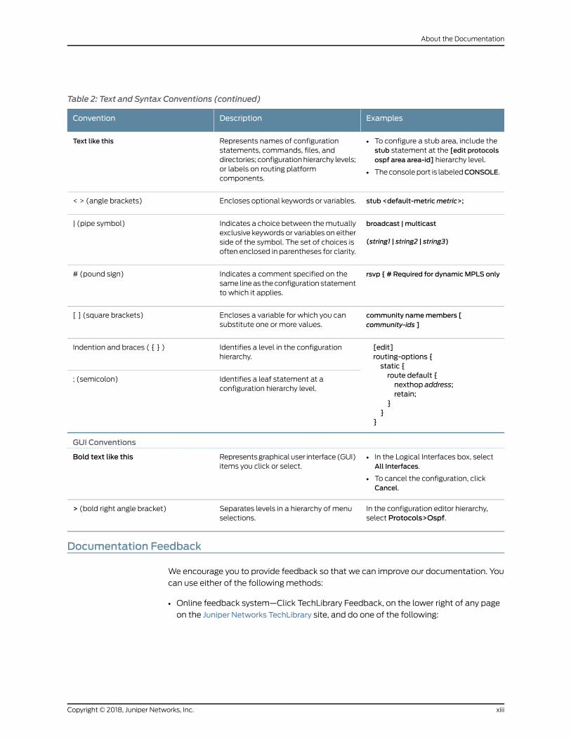
Table 2: Text and Syntax Conventions (continued)
ExamplesDescriptionConvention
• To configure a stub area, include thestub statement at the [edit protocolsospf area area-id] hierarchy level.
• Theconsoleport is labeledCONSOLE.
Represents names of configurationstatements, commands, files, anddirectories; configurationhierarchy levels;or labels on routing platformcomponents.
Text like this
stub <default-metricmetric>;Encloses optional keywords or variables.< > (angle brackets)
broadcast | multicast
(string1 | string2 | string3)
Indicates a choice between themutuallyexclusive keywords or variables on eitherside of the symbol. The set of choices isoften enclosed in parentheses for clarity.
| (pipe symbol)
rsvp { # Required for dynamicMPLS onlyIndicates a comment specified on thesame lineas theconfiguration statementto which it applies.
# (pound sign)
community namemembers [community-ids ]
Encloses a variable for which you cansubstitute one or more values.
[ ] (square brackets)
[edit]routing-options {static {route default {nexthop address;retain;
}}
}
Identifies a level in the configurationhierarchy.
Indention and braces ( { } )
Identifies a leaf statement at aconfiguration hierarchy level.
; (semicolon)
GUI Conventions
• In the Logical Interfaces box, selectAll Interfaces.
• To cancel the configuration, clickCancel.
Representsgraphicaluser interface(GUI)items you click or select.
Bold text like this
In the configuration editor hierarchy,select Protocols>Ospf.
Separates levels in a hierarchy of menuselections.
> (bold right angle bracket)
Documentation Feedback
We encourage you to provide feedback so that we can improve our documentation. You
can use either of the following methods:
• Online feedback system—Click TechLibrary Feedback, on the lower right of any page
on the Juniper Networks TechLibrary site, and do one of the following:
xiiiCopyright © 2018, Juniper Networks, Inc.
About the Documentation
• Click the thumbs-up icon if the information on the page was helpful to you.
• Click the thumbs-down icon if the information on the page was not helpful to you
or if you have suggestions for improvement, and use the pop-up form to provide
feedback.
• E-mail—Sendyourcommentsto [email protected]. Includethedocument
or topic name, URL or page number, and software version (if applicable).
Requesting Technical Support
Technical product support is available through the JuniperNetworksTechnicalAssistance
Center (JTAC). If you are a customer with an active J-Care or Partner Support Service
support contract, or are covered under warranty, and need post-sales technical support,
you can access our tools and resources online or open a case with JTAC.
• JTAC policies—For a complete understanding of our JTAC procedures and policies,
review the JTAC User Guide located at
https://www.juniper.net/us/en/local/pdf/resource-guides/7100059-en.pdf.
• Product warranties—For product warranty information, visit
https://www.juniper.net/support/warranty/.
• JTAC hours of operation—The JTAC centers have resources available 24 hours a day,
7 days a week, 365 days a year.
Self-Help Online Tools and Resources
For quick and easy problem resolution, Juniper Networks has designed an online
self-service portal called the Customer Support Center (CSC) that provides youwith the
following features:
• Find CSC offerings: https://www.juniper.net/customers/support/
• Search for known bugs: https://prsearch.juniper.net/
• Find product documentation: https://www.juniper.net/documentation/
• Find solutions and answer questions using our Knowledge Base: https://kb.juniper.net/
• Download the latest versions of software and review release notes:
https://www.juniper.net/customers/csc/software/
• Search technical bulletins for relevant hardware and software notifications:
https://kb.juniper.net/InfoCenter/
Copyright © 2018, Juniper Networks, Inc.xiv
SRX1500 Services Gateway Hardware Guide
• Join and participate in the Juniper Networks Community Forum:
https://www.juniper.net/company/communities/
• Open a case online in the CSC Case Management tool: https://www.juniper.net/cm/
Toverify serviceentitlementbyproduct serial number, useourSerialNumberEntitlement
(SNE) Tool: https://entitlementsearch.juniper.net/entitlementsearch/
Opening a Casewith JTAC
You can open a case with JTAC on theWeb or by telephone.
• Use the Case Management tool in the CSC at https://www.juniper.net/cm/.
• Call 1-888-314-JTAC (1-888-314-5822 toll-free in the USA, Canada, and Mexico).
For international or direct-dial options in countries without toll-free numbers, see
https://www.juniper.net/support/requesting-support.html.
xvCopyright © 2018, Juniper Networks, Inc.
About the Documentation

Copyright © 2018, Juniper Networks, Inc.xvi
SRX1500 Services Gateway Hardware Guide
CHAPTER 1
Overview
• SRX1500 Services Gateway Overview on page 17
• SRX1500 Chassis on page 18
• SRX1500 Cooling System on page 23
• SRX1500 Power System on page 23
SRX1500 Services Gateway Overview
• SRX1500 Services Gateway Overview on page 17
• SRX1500 Services Gateway Field Replaceable Units Overview on page 18
SRX1500 Services Gateway Overview
Juniper Networks SRX1500 Services Gateway expands the SRX Series family of security
platforms. The SRX1500 Services Gateway is a mid-range dynamic services gateway
that consolidates security functionality and uncompromised performance for small to
medium enterprises. With advanced security and threat mitigation capabilities, the
SRX1500 Services Gateway provides campus edge Integrated Security Appliance (ISA)
support.
The SRX1500 Services Gateway has amodular 1U chassis with twelve 1G Ethernet ports,
four 1G SFP ports, and four 10G SFP+ ports. It contains two slots for WAN Physical
Interface Modules (PIMs), one slot for an SSD device, and two slots for power supplies.
The SRX1500 Services Gateway is available in twomodels:
• SRX1500 (AC)–SRX1500 Services Gateway with a 120 GB SSD (with 100 GB usable
space) and AC power supply
• SRX1500 (DC)–SRX1500 Services Gateway with a 120 GB SSD (with 100 GB usable
space) and DC power supply
TheSRX1500ServicesGateway runs the Junosoperatingsystem(JunosOS)andsupports
the following features:
• Firewall support with key features such as IPsec and VPN
• Advanced security services (IPS, AppID, UTM) and threat mitigation capabilities
• High availability
17Copyright © 2018, Juniper Networks, Inc.

• QoS
• Secure boot
• Sky Advanced Threat Prevention
The services gateway runs the JunosOSand canbemanagedusing theCLI, JunosSpace,
and J-Web.
SRX1500 Services Gateway Field Replaceable Units Overview
Field-replaceable units (FRUs) are components that you can replace at your site. The
power supplies are the only FRUson theSRX1500ServicesGateway. Thepower supplies
(if redundant)arehot-swappable.Youcan removeand replace thepower supplywithout
powering off the services gateway or disrupting the services gateway functions.
See Also Required Tools and Parts for Replacing the SRX1500 Services Gateway Components
on page 70
•
• Replacing an AC Power Supply on the SRX1500 Services Gateway on page 70
• Replacing a DC Power Supply on the SRX1500 Services Gateway on page 72
RelatedDocumentation
SRX1500 Services Gateway Installation Overview on page 41•
SRX1500 Chassis
• SRX1500 Services Gateway Chassis Overview on page 18
• SRX1500 Services Gateway Front Panel on page 19
• SRX1500 Services Gateway Back Panel on page 22
SRX1500 Services Gateway Chassis Overview
The SRX1500 Services Gateway chassis is a rigid sheet metal structure that houses all
the other hardware components. The chassis weighs 15 lb. andmeasures 1.75 in. high,
17.5 in. wide, and 18.2 in. deep. The chassis installs in standard 600-mm deep (or larger)
enclosed cabinets or 19-in. equipment racks.
CAUTION: Before removingor installingcomponentsofa functioningservicesgateway, attach an electrostatic discharge (ESD) strap to an ESD point andplace the other end of the strap around your barewrist. Failure to use an ESDstrap could result in damage to the device.
The services gatewaymust be connected to earth ground during normal operation. The
protective earthing terminal on the rear of the chassis is provided to connect the services
gateway to ground. Additional grounding is provided to anAC-powered services gateway
when you plug its power supply into a grounded AC power receptacle.
Copyright © 2018, Juniper Networks, Inc.18
SRX1500 Services Gateway Hardware Guide
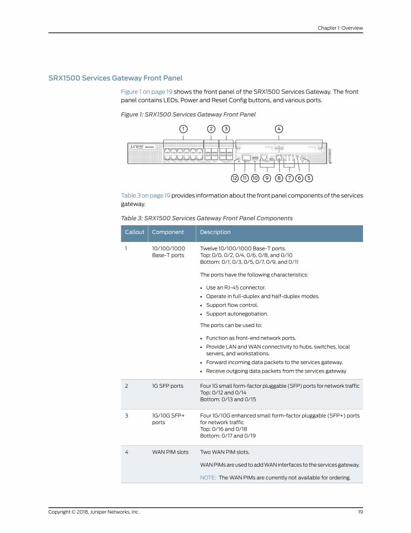
SRX1500 Services Gateway Front Panel
Figure 1 on page 19 shows the front panel of the SRX1500 Services Gateway. The front
panel contains LEDs, Power and Reset Config buttons, and various ports.
Figure 1: SRX1500 Services Gateway Front Panel
Table3onpage 19provides informationabout the frontpanel componentsof the services
gateway.
Table 3: SRX1500 Services Gateway Front Panel Components
DescriptionComponentCallout
Twelve 10/100/1000 Base-T ports.Top: 0/0, 0/2, 0/4, 0/6, 0/8, and 0/10Bottom: 0/1, 0/3, 0/5, 0/7, 0/9, and 0/11
The ports have the following characteristics:
• Use an RJ-45 connector.
• Operate in full-duplex and half-duplex modes.
• Support flow control.
• Support autonegotiation.
The ports can be used to:
• Function as front-end network ports.
• Provide LAN andWAN connectivity to hubs, switches, localservers, and workstations.
• Forward incoming data packets to the services gateway.
• Receive outgoing data packets from the services gateway
10/100/1000Base-T ports
1
Four 1Gsmall form-factor pluggable (SFP)ports for network trafficTop: 0/12 and 0/14Bottom: 0/13 and 0/15
1G SFP ports2
Four 1G/10G enhanced small form-factor pluggable (SFP+) portsfor network trafficTop: 0/16 and 0/18Bottom: 0/17 and 0/19
1G/10G SFP+ports
3
TwoWAN PIM slots.
WANPIMsareusedtoaddWANinterfaces to theservicesgateway.
NOTE: TheWAN PIMs are currently not available for ordering.
WAN PIM slots4
19Copyright © 2018, Juniper Networks, Inc.
Chapter 1: Overview

Table 3: SRX1500 Services Gateway Front Panel Components (continued)
DescriptionComponentCallout
Use the Power button to shut down the services gateway. On aservices gateway that has been previously shut down using thePowerbutton,when thepowerbutton ispressedagain theservicesgateway starts up.
Power button5
Returns the services gateway to the factory-default configuration.Reset configbutton
6
Indicate component and system status and troubleshootinginformation at a glance. See Table 4 on page 21.
LEDs7
Use themanagement (MGMT) port to connect to the device overthe network.
Managementport
8
• Serial—Connects a laptop to the services gateway for CLImanagement. The port uses an RJ-45 serial connection, isconfiguredasDTE,andsupports theRS-232(EIA-232)standard.
• USB—Connects a laptop to the services gateway for CLImanagement throughaUSB interface.TheportacceptsaMini-Btype USB cable plug. A USB cable with Mini-B and Type A USBplugs is suppliedwith theservicesgateway.Touse themini-USBconsole port, you must download a USB driver to themanagement device from the Silicon Labs page.
Console port9
TheservicesgatewayhasoneUSBport thatacceptsaUSBstoragedevice.
USB port10
Dedicated Gigabit Ethernet SFP port to synchronize data andmaintain state information in a chassis cluster setup.
HA control port11
For personal safety, while working on the services gateway, usethe ESD outlet to plug in an ESD grounding strap to prevent yourbody from sending static charges to the services gateway.
ESD point12
Copyright © 2018, Juniper Networks, Inc.20
SRX1500 Services Gateway Hardware Guide
NOTE: For information on supported transceivers, see the Hardware
Compatibility Tool. Note that the HA port supports only the following
transceivers:
• EX-SFP-1GE-LH
• EX-SFP-1GE-LX
• EX-SFP-1GE-SX
• EX-SFP-1GE-SX-ET
• QFX-SFP-1GE-LX
• QFX-SFP-1GE-SX
• SRX-SFP-1GE-LH
• SRX-SFP-1GE-LX
• SRX-SFP-1GE-LX-ET
• SRX-SFP-1GE-SX
• SRX-SFP-1GE-SX-ET
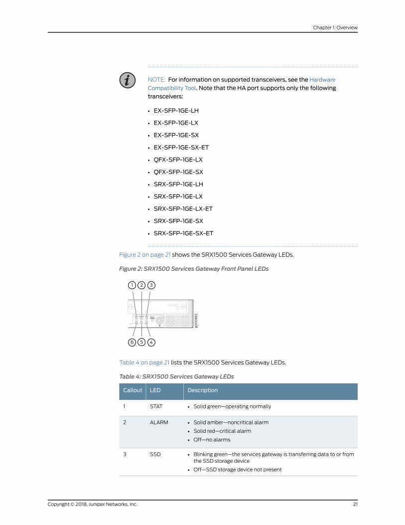
Figure 2 on page 21 shows the SRX1500 Services Gateway LEDs.
Figure 2: SRX1500 Services Gateway Front Panel LEDs
Table 4 on page 21 lists the SRX1500 Services Gateway LEDs.
Table 4: SRX1500 Services Gateway LEDs
DescriptionLEDCallout
• Solid green—operating normallySTAT1
• Solid amber—noncritical alarm
• Solid red—critical alarm
• Off—no alarms
ALARM2
• Blinking green—the services gateway is transferring data to or fromthe SSD storage device
• Off—SSD storage device not present
SSD3
21Copyright © 2018, Juniper Networks, Inc.
Chapter 1: Overview
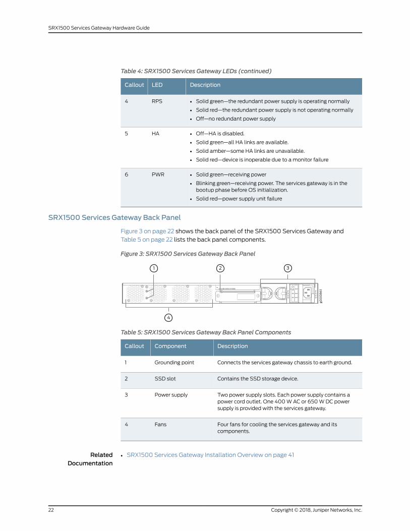
Table 4: SRX1500 Services Gateway LEDs (continued)
DescriptionLEDCallout
• Solid green—the redundant power supply is operating normally
• Solid red—the redundant power supply is not operating normally
• Off—no redundant power supply
RPS4
• Off—HA is disabled.
• Solid green—all HA links are available.
• Solid amber—some HA links are unavailable.
• Solid red—device is inoperable due to amonitor failure
HA5
• Solid green—receiving power
• Blinking green—receiving power. The services gateway is in thebootup phase before OS initialization.
• Solid red—power supply unit failure
PWR6
SRX1500 Services Gateway Back Panel
Figure 3 on page 22 shows the back panel of the SRX1500 Services Gateway and
Table 5 on page 22 lists the back panel components.
Figure 3: SRX1500 Services Gateway Back Panel
Table 5: SRX1500 Services Gateway Back Panel Components
DescriptionComponentCallout
Connects the services gateway chassis to earth ground.Grounding point1
Contains the SSD storage device.SSD slot2
Two power supply slots. Each power supply contains apower cord outlet. One 400WAC or 650WDC powersupply is provided with the services gateway.
Power supply3
Four fans for cooling the services gateway and itscomponents.
Fans4
RelatedDocumentation
SRX1500 Services Gateway Installation Overview on page 41•
Copyright © 2018, Juniper Networks, Inc.22
SRX1500 Services Gateway Hardware Guide

SRX1500 Cooling System
The services gatewayhas a single fan tray that contains four fixed fans. The fan controller
constantlymonitors the temperature of the services gatewayand its components. Under
normal operating conditions, the fans function at lower than full speed.
If any one of the four fans fails, the services gateway generates a warning but keeps the
system running. If the temperature keeps rising, the services gateway lowers the power
consumption by reducing the performance or shutting down some of the chassis
components. However, if the ambient maximum temperature exceeds the warning level
and the system cannot be adequately cooled, then the services gateway shuts down the
system and hardware components completely.
RelatedDocumentation
SRX1500 Services Gateway Clearance Requirements for Airflow and Hardware
Maintenance on page 34
•
SRX1500 Power System
• SRX1500 Services Gateway Power Supply on page 23
• SRX1500 Services Gateway Supported AC Power Cords on page 25
• SRX1500 Services Gateway AC Power Supply Electrical Specifications on page 26
• SRX1500 Services Gateway DC Power Supply Electrical Specifications on page 26
• SRX1500 Services Gateway DC Power Cable Specifications on page 26
SRX1500 Services Gateway Power Supply
Thepower suppliesare locatedon the rearof thechassis. TheSRX1500ServicesGateway
uses either one AC or one DC power supply unit.
A second AC or DC power supply can be used with its matching type of power supply to
provide redundancy. Eachpower supply providespower toall components in the services
gateway. When two power supplies are present, they share power almost equally within
a fully populated system. The two power supplies provide power redundancy. If one
power supply fails or is removed, the remaining power supply redistributes the electrical
loadwithout interruption.Theservicesgateway reassesses thepower required tosupport
its configuration and issues errors if the available power is insufficient.
Each power supply is cooled by its own internal cooling system.
NOTE: Only redundant power supplies (AC or DC) support hot-swappablefunctionality.
Figure 4 on page 24 shows the AC power supply.
23Copyright © 2018, Juniper Networks, Inc.
Chapter 1: Overview

Figure 4: AC Power Supply for the SRX1500 Services Gateway
Figure 5 on page 24 shows the DC power supply.
Figure 5: DC Power Supply for the SRX1500 Services Gateway
CAUTION: Do notmix AC and DC power supplies within the same servicesgateway. Damage to the devicemight occur.
The power supplies produce and distribute different output voltages to the services
gateway components according to their voltage requirements.
Table 6 on page 24 lists the power consumption values for the power supplies.
Table 6: Component Power Output/Consumption
Output/ConsumptionPower Supply
400W@12 V400WAC power supply
650W@12 V650WDC power supply
See Also Powering On the SRX1500 Services Gateway on page 53•
• Powering Off the SRX1500 Services Gateway on page 54
Copyright © 2018, Juniper Networks, Inc.24
SRX1500 Services Gateway Hardware Guide

SRX1500 Services Gateway Supported AC Power Cords
WARNING: The AC power cord for the services gateway is intended for usewith the services gateway only and not for any other use.
NOTE: In North America, AC power cordsmust not exceed 4.5m(approximately 14.75 ft) in length, to comply with National Electrical code(NEC) Section 400-8 (NFPA 75, 5-2.2) and 210-52, and Canadian ElectricalCode (CEC) Section 4-010(3).
Table 7 on page 25 provides power cord specifications, and Figure 6 on page 25 depicts
the plug on the AC power cord provided for each country or region.
Table 7: AC Power Cord Specifications
Plug StandardsElectrical SpecificationCountry
AS/NZ 3112-1993250 VAC, 10 A, 50 HzAustralia
GB2099.1 1996 andGB 1002 1996(CH1-10P)
250 VAC, 10 A, 50 HzChina
CEE (7) VII250 VAC, 10 A, 50 HzEurope (except Italy and United Kingdom)
CEI 23-16/VII250 VAC, 10 A, 50 HzItaly
JIS 8303125 VAC, 12 A, 50 or 60 HzJapan
NEMA 5-15125 VAC, 10 A, 60 HzNorth America
BS 1363A250 VAC, 10 A, 50 HzUnited Kingdom
Figure 6: AC Plug Types
NOTE: Power cords and cablesmust not block access to services gatewaycomponents or drape where peoplemight trip on them.
25Copyright © 2018, Juniper Networks, Inc.
Chapter 1: Overview
SRX1500 Services Gateway AC Power Supply Electrical Specifications
Table 8 on page 26 lists the AC power supply electrical specifications for the SRX1500
Services Gateway.
Table 8: AC Power Supply Electrical Specifications for the SRX1500 Services Gateway
SpecificationPower Requirement
100 to 127 V ~ 2.5 A, 200 to 240 V ~ 1.3 AAC input voltage
47 to 63 HzAC input line frequency
SRX1500 Services Gateway DC Power Supply Electrical Specifications
Table 9 on page 26 lists the DC power supply electrical specifications for the SRX1500
Services Gateway.
Table 9: DC Power Supply Electrical Specifications for the SRX1500 Services Gateway
SpecificationPower Requirement
–44 to –72 VDCDC input voltage
6.2 AmaximumDC system current rating
SRX1500 Services Gateway DC Power Cable Specifications
The DC power supply in slot 0must be powered by dedicated power feeds derived from
feed A, and the DC power supply in slot 1 must be powered by dedicated power feeds
derived from feed B. This configuration provides the commonly deployed A/B feed
redundancy for the system.
CAUTION: Youmust ensure that power connectionsmaintain the properpolarity. The power source cablesmight be labeled (+) and (–) to indicatetheir polarity. There is no standard color coding for DC power cables. Thecolor coding used by the external DC power source at your site determinesthe color coding for the leads on the power cables that attach to the terminalstuds on each power supply.
WARNING: For field-wiring connections, use copper conductors only. Forotherelectrical safety information, see “SRX1500ServicesGatewayElectricalWiring Guidelines” on page 32.
CAUTION: Powercordsandcablesmustnotblockaccess toservicesgatewaycomponents or drape where people could trip on them.
Copyright © 2018, Juniper Networks, Inc.26
SRX1500 Services Gateway Hardware Guide
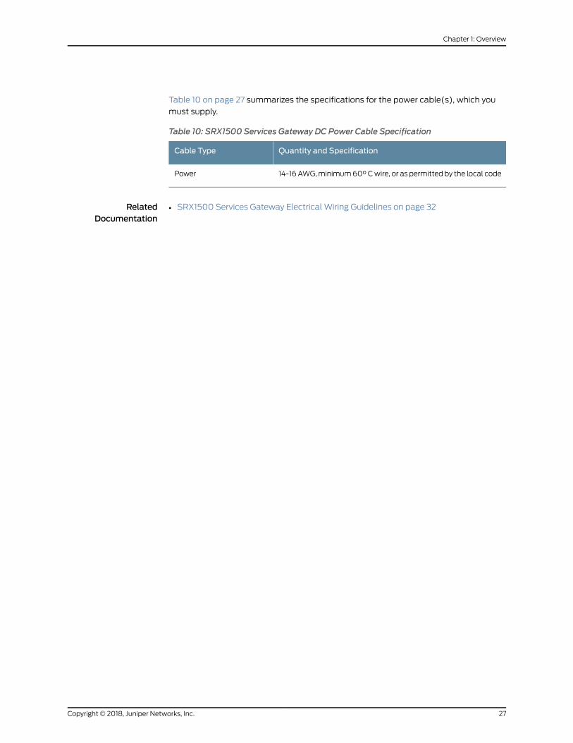
Table 10 on page 27 summarizes the specifications for the power cable(s), which you
must supply.
Table 10: SRX1500 Services Gateway DC Power Cable Specification
Quantity and SpecificationCable Type
14-16AWG,minimum60°Cwire, or as permitted by the local codePower
RelatedDocumentation
• SRX1500 Services Gateway Electrical Wiring Guidelines on page 32
27Copyright © 2018, Juniper Networks, Inc.
Chapter 1: Overview

Copyright © 2018, Juniper Networks, Inc.28
SRX1500 Services Gateway Hardware Guide

CHAPTER 2
Site Planning, Preparation, andSpecifications
• Site Preparation Checklist for the SRX1500 Services Gateway on page 29
• SRX1500 Site Guidelines and Requirements on page 31
• SRX1500 Transceiver Specifications and Pinouts on page 37
Site Preparation Checklist for the SRX1500 Services Gateway
Table 11 on page 29 provides a checklist of tasks you need to performwhen preparing a
site for installing the SRX1500 Services Gateway.
Table 11: Site Preparation Checklist for SRX1500 Services Gateway Installation
NotesDatePerformedByAdditional InformationItem or Task
Power
“SRX1500 ServicesGateway Electrical WiringGuidelines” on page 32
Measure distance betweenexternal power sources anddevice installation site.
“Connecting the SRX1500Services GatewayGrounding Cable” onpage 46
Locate sites for connection ofsystem grounding.
“SRX1500 ServicesGateway AC Power SupplyElectricalSpecifications”onpage 26 and “SRX1500ServicesGatewayDCPowerSupply ElectricalSpecifications” on page 26
Calculate thepowerconsumptionand requirements.
Environment
29Copyright © 2018, Juniper Networks, Inc.
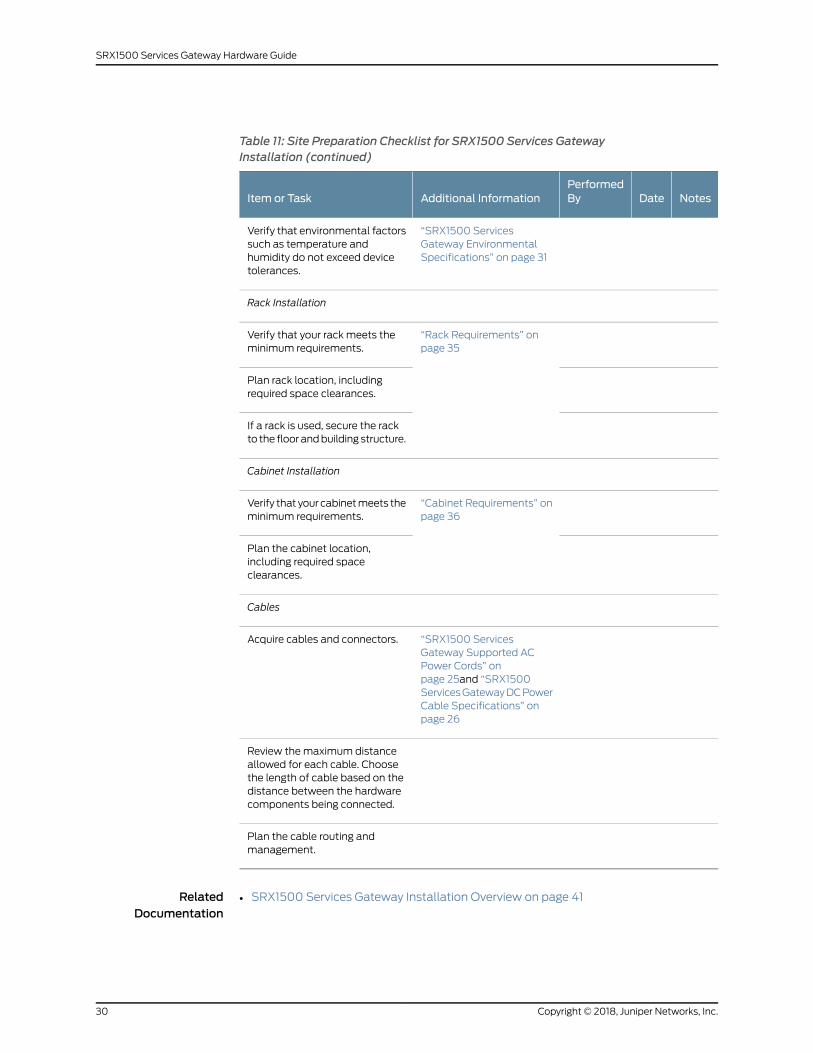
Table 11: Site Preparation Checklist for SRX1500 Services GatewayInstallation (continued)
NotesDatePerformedByAdditional InformationItem or Task
“SRX1500 ServicesGateway EnvironmentalSpecifications” on page 31
Verify that environmental factorssuch as temperature andhumidity do not exceed devicetolerances.
Rack Installation
“Rack Requirements” onpage 35
Verify that your rack meets theminimum requirements.
Plan rack location, includingrequired space clearances.
If a rack is used, secure the rackto the floor andbuilding structure.
Cabinet Installation
“Cabinet Requirements” onpage 36
Verify that your cabinetmeets theminimum requirements.
Plan the cabinet location,including required spaceclearances.
Cables
“SRX1500 ServicesGateway Supported ACPower Cords” onpage 25and “SRX1500ServicesGatewayDCPowerCable Specifications” onpage 26
Acquire cables and connectors.
Review themaximum distanceallowed for each cable. Choosethe length of cable based on thedistance between the hardwarecomponents being connected.
Plan the cable routing andmanagement.
RelatedDocumentation
SRX1500 Services Gateway Installation Overview on page 41•
Copyright © 2018, Juniper Networks, Inc.30
SRX1500 Services Gateway Hardware Guide
SRX1500 Site Guidelines and Requirements
• SRX1500 Services Gateway General Site Installation Guidelines on page 31
• SRX1500 Services Gateway Environmental Specifications on page 31
• SRX1500 Services Gateway Electrical Wiring Guidelines on page 32
• SRX1500 Services Gateway Grounding Specifications on page 33
• SRX1500 Services Gateway Physical Specifications on page 34
• SRX1500 Services Gateway Clearance Requirements for Airflow and Hardware
Maintenance on page 34
• Rack Requirements on page 35
• Cabinet Requirements on page 36
SRX1500 Services Gateway General Site Installation Guidelines
The following precautions help you plan an acceptable operating environment for your
SRX1500 Services Gateway and avoid environmentally caused equipment failures:
• For the cooling system to function properly, the airflow around the chassis must be
unrestricted. Allow sufficient clearance between the front and back of the chassis and
adjacentequipment. Ensure that there isadequatecirculation in the installation location.
• Follow the ESD procedures to avoid damaging equipment. Static discharge can cause
components to fail completely or intermittently over time. For more information, see
“Prevention of Electrostatic Discharge Damage” on page 92.
• Ensure that the blank panels are installed into empty slots to prevent any interruption
or reduction in the flow of air across internal components.
NOTE: Install theservicesgatewayonly in restrictedareas, suchasdedicatedequipment roomsandequipmentclosets, inaccordancewithArticles 110–16,110–17, and 110–18 of the National Electrical Code, ANSI/NFPA 70.
SRX1500 Services Gateway Environmental Specifications
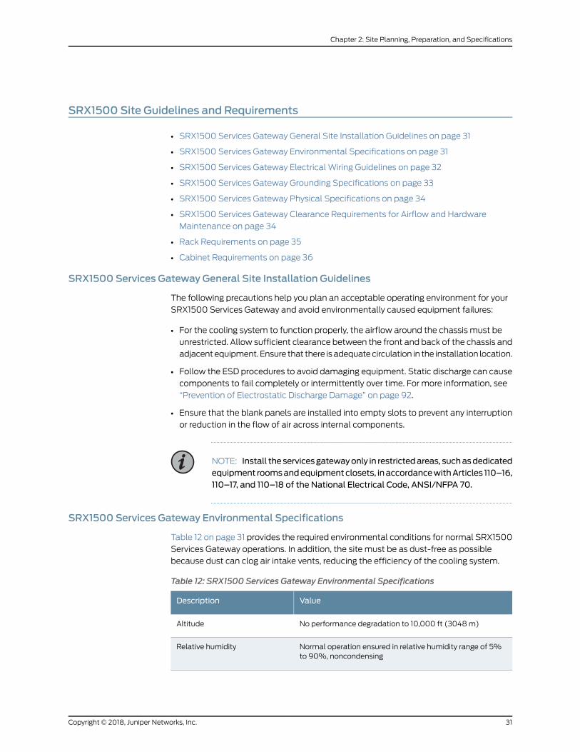
Table 12 on page 31 provides the required environmental conditions for normal SRX1500
Services Gateway operations. In addition, the site must be as dust-free as possible
because dust can clog air intake vents, reducing the efficiency of the cooling system.
Table 12: SRX1500 Services Gateway Environmental Specifications
ValueDescription
No performance degradation to 10,000 ft (3048m)Altitude
Normal operation ensured in relative humidity range of 5%to 90%, noncondensing
Relative humidity
31Copyright © 2018, Juniper Networks, Inc.
Chapter 2: Site Planning, Preparation, and Specifications
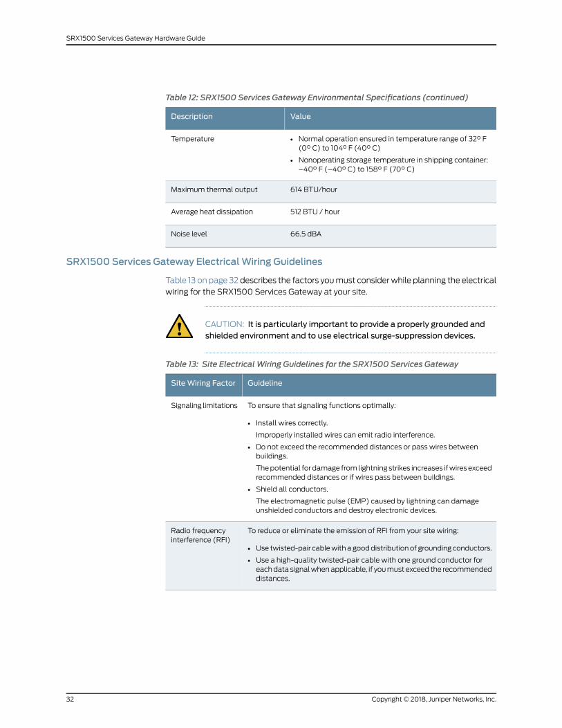
Table 12: SRX1500 Services Gateway Environmental Specifications (continued)
ValueDescription
• Normal operation ensured in temperature range of 32° F(0° C) to 104° F (40° C)
• Nonoperating storage temperature in shipping container:–40° F (–40° C) to 158° F (70° C)
Temperature
614 BTU/hourMaximum thermal output
512 BTU / hourAverage heat dissipation
66.5 dBANoise level
SRX1500 Services Gateway ElectricalWiring Guidelines
Table 13 on page 32 describes the factors youmust considerwhile planning the electrical
wiring for the SRX1500 Services Gateway at your site.
CAUTION: It is particularly important to provide a properly grounded andshielded environment and to use electrical surge-suppression devices.
Table 13: Site Electrical Wiring Guidelines for the SRX1500 Services Gateway
GuidelineSiteWiring Factor
To ensure that signaling functions optimally:
• Install wires correctly.
Improperly installed wires can emit radio interference.
• Do not exceed the recommended distances or pass wires betweenbuildings.
Thepotential fordamage from lightningstrikes increases ifwiresexceedrecommended distances or if wires pass between buildings.
• Shield all conductors.
The electromagnetic pulse (EMP) caused by lightning can damageunshielded conductors and destroy electronic devices.
Signaling limitations
To reduce or eliminate the emission of RFI from your site wiring:
• Use twisted-pair cablewithagooddistributionof groundingconductors.
• Use a high-quality twisted-pair cable with one ground conductor foreachdata signalwhenapplicable, if youmustexceed the recommendeddistances.
Radio frequencyinterference (RFI)
Copyright © 2018, Juniper Networks, Inc.32
SRX1500 Services Gateway Hardware Guide

Table 13: SiteElectricalWiringGuidelines for theSRX1500ServicesGateway(continued)
GuidelineSiteWiring Factor
Provide a properly grounded and shielded environment and use electricalsurge-suppression devices.
Strong sources of electromagnetic interference (EMI) can cause thefollowing damage:
• Destroy the signal drivers and receivers in the device
• Conduct power surges over the lines into the equipment, resulting in anelectrical hazard
TIP: If your site is susceptible to problems with EMC, particularly fromlightning or radio transmitters, youmight want to seek expert advice.
Electromagneticcompatibility (EMC)
WARNING: Some ports are designed for use as intrabuilding interfaces onlyType 2 or Type 4 ports, the battery return connection is to be treated as anIsolated DC return (that is, DC-I), as defined in GR-1089-CORE and requireisolation from the exposedOSP cabling. To complywith NEBS requirementsand protect against lightning surges and commercial power disturbances,the intrabuilding port(s) of the device MUSTNOT bemetallically connectedto interfaces that connect to the OSP or its wiring. The intrabuilding port(s)of the device is suitable for connection to intrabuilding or unexposed wiringor cabling only. Theaddition of primary protectors is not sufficient protectionto connect these interfacesmetallically to OSPwiring.
SRX1500 Services Gateway Grounding Specifications
Tomeet safety and electromagnetic interference (EMI) requirements and to ensure
proper operation, the SRX1500 Services Gatewaymust be adequately grounded before
power is connected. Youmust provide a grounding lug to connect the services gateway
to earth ground.
WARNING: Before you connect power to the services gateway, a licensedelectricianmust attach a cable lug to the grounding and power cables thatyou supply. A cablewith an incorrectly attached lug can damage the servicesgateway (for example, by causing a short circuit).
The services gateway chassis has one grounding point on the back panel. The grounding
point consists of two threaded holes spaced 0.625 in. (15.86mm) apart. The grounding
point holes fit M5 screws.
Table 14 on page 34 lists the specifications of the grounding cable used with the device.
33Copyright © 2018, Juniper Networks, Inc.
Chapter 2: Site Planning, Preparation, and Specifications
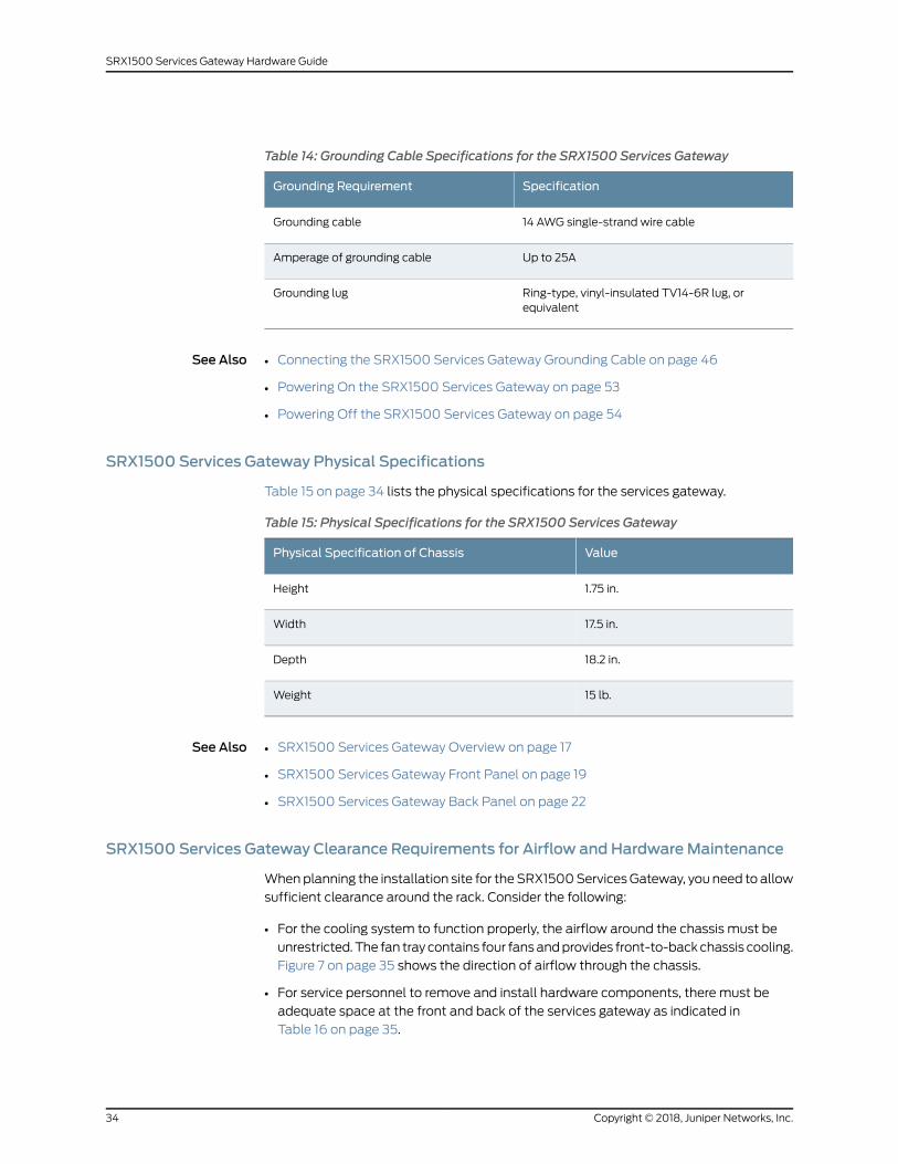
Table 14: Grounding Cable Specifications for the SRX1500 Services Gateway
SpecificationGrounding Requirement
14 AWG single-strand wire cableGrounding cable
Up to 25AAmperage of grounding cable
Ring-type, vinyl-insulated TV14-6R lug, orequivalent
Grounding lug
See Also Connecting the SRX1500 Services Gateway Grounding Cable on page 46•
• Powering On the SRX1500 Services Gateway on page 53
• Powering Off the SRX1500 Services Gateway on page 54
SRX1500 Services Gateway Physical Specifications
Table 15 on page 34 lists the physical specifications for the services gateway.
Table 15: Physical Specifications for the SRX1500 Services Gateway
ValuePhysical Specification of Chassis
1.75 in.Height
17.5 in.Width
18.2 in.Depth
15 lb.Weight
See Also SRX1500 Services Gateway Overview on page 17•
• SRX1500 Services Gateway Front Panel on page 19
• SRX1500 Services Gateway Back Panel on page 22
SRX1500 Services Gateway Clearance Requirements for Airflow and HardwareMaintenance
Whenplanning the installation site for theSRX1500ServicesGateway, you need to allow
sufficient clearance around the rack. Consider the following:
• For the cooling system to function properly, the airflow around the chassis must be
unrestricted. The fan tray contains four fansandprovides front-to-backchassis cooling.
Figure 7 on page 35 shows the direction of airflow through the chassis.
• For service personnel to remove and install hardware components, there must be
adequate space at the front and back of the services gateway as indicated in
Table 16 on page 35.
Copyright © 2018, Juniper Networks, Inc.34
SRX1500 Services Gateway Hardware Guide

• If you are mounting the services gateway in a rack with other equipment, ensure that
the exhaust from other equipment does not blow into the intake vents of the chassis.
Table 16 on page 35 provides information about the clearance requirements for
maintainingoptimumairflowand thedistancesnecessary to facilitateeasymaintenance
of the services gateway.
Table 16: Clearance Requirements for the SRX1500 Services Gateway
Requirement for ClearanceRecommendedClearanceLocation
Space for service personnel to removeand install hardware components
8.7 in. (22 cm)Front of the chassis
Space for service personnel to removeand install hardware components
17.4 in. (44.2 cm)Rear of the chassis
Space for cable management andorganization
2.5 in. (6.35 cm)Between front-mounting flangeand rack or cabinet edge
Space for the cooling system tofunction properly and to maintainunrestrictedairflowaround thechassis
6.0 in. (15.24 cm)Between both sides of thechassis and anynon-heat-producing surfacesuch as a wall or cabinet side
Figure 7 on page 35 shows the airflow through the chassis.
Figure 7: Airflow Through the Chassis
g000
866
PortsFRUs
Top down view
Rack Requirements
When installing the services gateway in a rack, youmust ensure that the rack complies
with a 1U (19 in. or 48.7 cm) rack as defined in Cabinets, Racks, Panels, and Associated
35Copyright © 2018, Juniper Networks, Inc.
Chapter 2: Site Planning, Preparation, and Specifications
Equipment (documentnumberEIA-310-D),publishedby theElectronic IndustriesAlliance
(http://www.ecaus.org/eia/site/index.html).
When selecting a rack, ensure that the physical characteristics of the rack comply with
the following specifications:
• The outer edges of the mounting brackets extend the width of either chassis to 19 in.
(48.3 cm).
• The front of the chassis extends approximately 0.5 in. (1.27 cm) beyond themounting
ears.
• Maximumpermissible ambient temperaturewhen two devices are placed side by side
in a 19 in. rack is 40° C.
The spacing of themounting brackets and flange holes on the rack and devicemounting
brackets are as follows:
• The holes within each rack set are spaced at 1 U (1.75 in. or 4.5 cm).
• Themounting brackets and front-mount flanges used to attach the chassis to a rack
are designed to fasten to holes spaced at rack distances of 1 U (1.75 in.).
• Themounting holes in the mounting brackets provided with the device are spaced
1.25 in. (3.2 cm) apart (top and bottommounting hole).
Always secure the rack in which you are installing the services gateway to the structure
of the building. If your geographical area is subject to earthquakes, bolt the rack to the
floor. For maximum stability, also secure the rack to ceiling brackets.
Cabinet Requirements
You can install the services gateway in a 19 in. (48.7 cm) cabinet as defined in Cabinets,
Racks, Panels, and Associated Equipment (document number EIA-310-D) published by
the Electronic Industries Alliance (http://www.ecaus.org/eia/site/index.html). Youmust
mount the services gateway horizontally in the cabinet using appropriate rack adapters.
When selecting a cabinet, ensure that it meets the following specifications:
• The cabinet is at least 1U (3.50 in. or 8.89 cm) and can accommodate the services
gateway.
• The outer edges of the mounting brackets extend the width of either chassis to 19 in.
(48.7 cm), and the front of the chassis extends approximately 0.5 in. (1.27 cm) beyond
themounting brackets.
• Theminimum total clearance inside the cabinet is 30.7 in. (78 cm) between the inside
of the front door and the inside of the rear door.
NOTE: A cabinet larger than theminimum required provides better airflowand reduces the chance of overheating.
Copyright © 2018, Juniper Networks, Inc.36
SRX1500 Services Gateway Hardware Guide
When youmount the services gateway in a cabinet, youmust ensure that ventilation
through the cabinet is sufficient to prevent overheating. Consider the following when
planning for chassis cooling:
• Ensure that thecool air supply youprovide through thecabinet canadequatelydissipate
the thermal output of the services gateway.
• Install the services gateway as close as possible to the front of the cabinet so that the
cable management system clears the inside of the front door. Installing the chassis
close to the front of the cabinet maximizes the clearance in the rear of the cabinet for
critical airflow.
• Route and dress all cables tominimize the blockage of airflow to and from the chassis.
SRX1500 Transceiver Specifications and Pinouts
• SRX1500 Transceiver Support on page 37
• RJ-45 Connector Pinouts for the SRX1500 Services Gateway Ethernet Port on page 37
• RJ-45 Connector Pinouts for the SRX1500 Services Gateway Console Port on page 38
• Mini-USB Connector Pinouts for the SRX1500 Services Gateway Console
Port on page 38
SRX1500 Transceiver Support
You can find information about the pluggable transceivers supported on your Juniper
Networks device by using the Hardware Compatibility Tool. In addition to transceiver
and connector type, the optical and cable characteristics—where applicable—are
documented for each transceiver. TheHardwareCompatibilityTool enables you to search
by product, displaying all the transceivers supported on that device, or category, by
interface speed or type. The list of supported transceivers for the SRX1500 is located at
https://apps.juniper.net/hct/product/#prd=SRX1500.
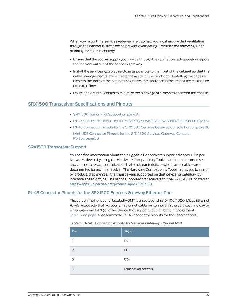
RJ-45 Connector Pinouts for the SRX1500 Services Gateway Ethernet Port
Theporton the frontpanel labeledMGMT isanautosensing 10/100/1000-MbpsEthernet
RJ-45 receptacle that accepts an Ethernet cable for connecting the services gateway to
amanagement LAN (or other device that supports out-of-bandmanagement).
Table 17 on page 37 describes the RJ-45 connector pinouts for the Ethernet port.
Table 17: RJ-45 Connector Pinouts for Services Gateway Ethernet Port
SignalPin
TX+1
TX-2
RX+3
Termination network4
37Copyright © 2018, Juniper Networks, Inc.
Chapter 2: Site Planning, Preparation, and Specifications
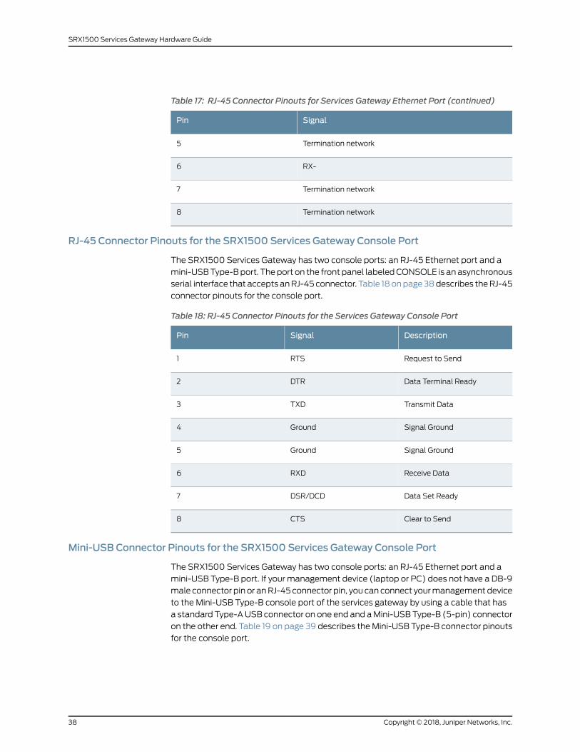
Table 17: RJ-45 Connector Pinouts for Services Gateway Ethernet Port (continued)
SignalPin
Termination network5
RX-6
Termination network7
Termination network8
RJ-45 Connector Pinouts for the SRX1500 Services Gateway Console Port
The SRX1500 Services Gateway has two console ports: an RJ-45 Ethernet port and a
mini-USBType-Bport. The port on the front panel labeledCONSOLE is an asynchronous
serial interface that accepts anRJ-45 connector. Table 18onpage38describes theRJ-45
connector pinouts for the console port.
Table 18: RJ-45 Connector Pinouts for the Services Gateway Console Port
DescriptionSignalPin
Request to SendRTS1
Data Terminal ReadyDTR2
Transmit DataTXD3
Signal GroundGround4
Signal GroundGround5
Receive DataRXD6
Data Set ReadyDSR/DCD7
Clear to SendCTS8
Mini-USB Connector Pinouts for the SRX1500 Services Gateway Console Port
The SRX1500 Services Gateway has two console ports: an RJ-45 Ethernet port and a
mini-USB Type-B port. If your management device (laptop or PC) does not have a DB-9
male connector pin or anRJ-45 connector pin, you can connect yourmanagement device
to the Mini-USB Type-B console port of the services gateway by using a cable that has
a standard Type-AUSB connector on one end and aMini-USBType-B (5-pin) connector
on the other end. Table 19 on page 39 describes theMini-USB Type-B connector pinouts
for the console port.
Copyright © 2018, Juniper Networks, Inc.38
SRX1500 Services Gateway Hardware Guide
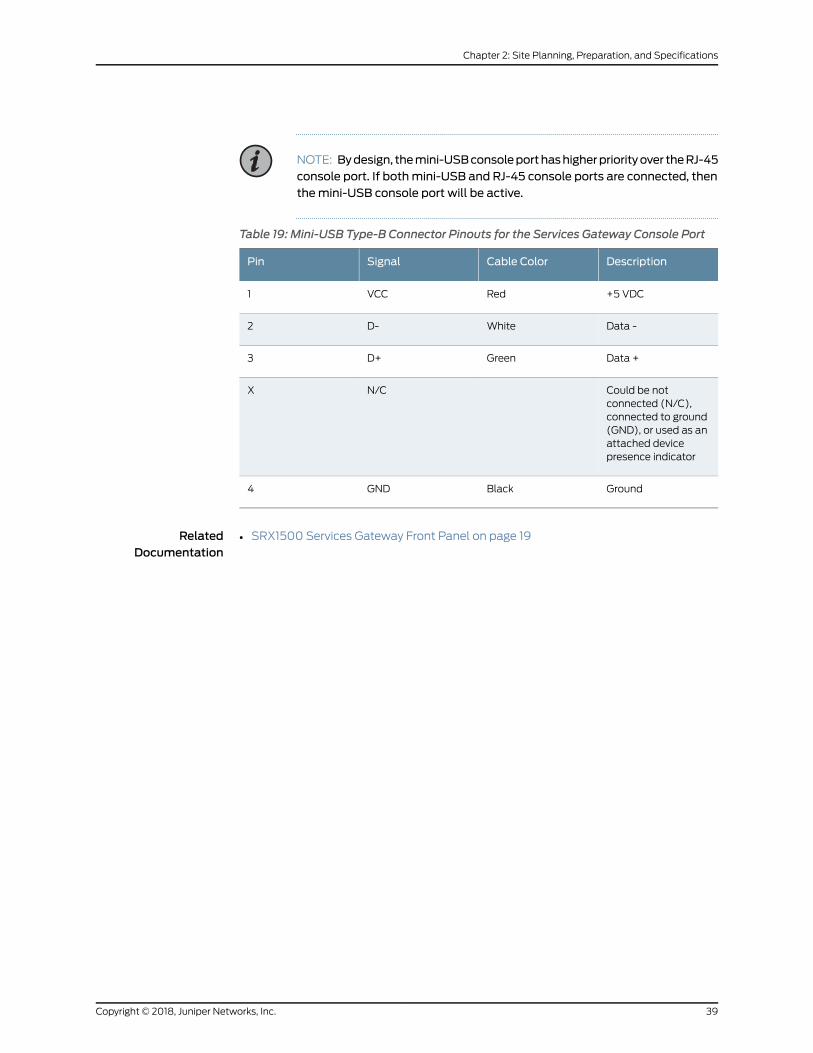
NOTE: Bydesign, themini-USBconsoleporthashigherpriorityover theRJ-45console port. If bothmini-USB and RJ-45 console ports are connected, thenthemini-USB console port will be active.
Table 19: Mini-USB Type-B Connector Pinouts for the Services Gateway Console Port
DescriptionCable ColorSignalPin
+5 VDCRedVCC1
Data -WhiteD-2
Data +GreenD+3
Could be notconnected (N/C),connected to ground(GND), or used as anattached devicepresence indicator
N/CX
GroundBlackGND4
RelatedDocumentation
• SRX1500 Services Gateway Front Panel on page 19
39Copyright © 2018, Juniper Networks, Inc.
Chapter 2: Site Planning, Preparation, and Specifications

Copyright © 2018, Juniper Networks, Inc.40
SRX1500 Services Gateway Hardware Guide
CHAPTER 3
Initial Installation and Configuration
• SRX1500 Services Gateway Installation Overview on page 41
• Unpacking and Mounting the SRX1500 on page 42
• Connecting the SRX1500 to Power on page 45
• Connecting the SRX1500 to External Devices on page 54
• Configuring Junos OS on the SRX1500 on page 56
SRX1500 Services Gateway Installation Overview
After you have prepared the site for installation and unpacked the SRX1500 Services
Gateway, you are ready to install the device. It is important to proceed through the
installation process in the following order:
1. Review the safety guidelines explained in “General Electrical Safety Guidelines and
Warnings” on page 103.
2. Prepare the services gateway for installation as described in “Preparing the SRX1500
Services Gateway for Rack-Mount Installation” on page 43.
3. Install the services gatewayasdescribed in “Installing theSRX1500ServicesGateway
in a Rack” on page 44.
4. Connect cables to external devicesasdescribed in “Connecting theSRX1500Services
Gateway to a Network for Out-of-Band Management” on page 55 and “Connecting
the SRX1500 Services Gateway to a Management Console” on page 55.
5. Connect the grounding cable as described in “Connecting the SRX1500 Services
Gateway Grounding Cable” on page 46.
6. Power on the services gateway as described in “Powering On the SRX1500 Services
Gateway” on page 53.
41Copyright © 2018, Juniper Networks, Inc.
Unpacking andMounting the SRX1500
• Unpacking the SRX1500 Services Gateway on page 42
• Verifying Parts Received with the SRX1500 Services Gateway on page 42
• Preparing the SRX1500 Services Gateway for Rack-Mount Installation on page 43
• Installing the SRX1500 Services Gateway in a Rack on page 44
Unpacking the SRX1500 Services Gateway
The SRX1500Services Gateway is shipped in a cardboard carton and securedwith foam
packingmaterial. Thecartonalso containsanaccessoryboxandquick-start instructions.
NOTE: The services gateway is maximally protected inside the cardboardcarton. Do not unpack it until you are ready to begin installation.
To unpack the SRX1500 Services Gateway:
1. Move thecardboardcarton toastagingareaasclose to the installation siteaspossible,
where you have enough room to remove the components from the chassis.
2. Position the cardboard carton with the arrows pointing up.
3. Carefully open the top of the cardboard carton.
4. Remove the foam covering the top of the services gateway.
5. Remove the accessory box.
6. Verify theparts receivedagainst the lists in “VerifyingPartsReceivedwith theSRX1500
Services Gateway” on page 42.
7. Store the brackets and bolts inside the accessory box.
8. Save the shipping carton and packing materials in case you need to move or ship the
services gateway at a later time.
Verifying Parts Receivedwith the SRX1500 Services Gateway
The SRX1500 Services Gateway shipment package contains a packing list. Check the
parts in the shipment against the items on the packing list. The packing list specifies the
part numbers and carries a brief description of each part in your order.
If any part is missing, contact a customer service representative.
Copyright © 2018, Juniper Networks, Inc.42
SRX1500 Services Gateway Hardware Guide
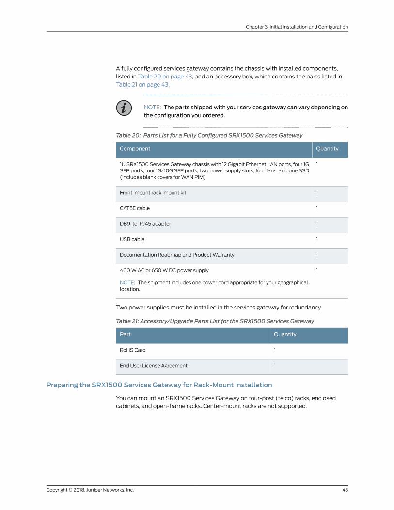
A fully configured services gateway contains the chassis with installed components,
listed in Table 20 on page 43, and an accessory box, which contains the parts listed in
Table 21 on page 43.
NOTE: The parts shippedwith your services gateway can vary depending onthe configuration you ordered.
Table 20: Parts List for a Fully Configured SRX1500 Services Gateway
QuantityComponent
11U SRX1500 Services Gateway chassis with 12 Gigabit Ethernet LAN ports, four 1GSFP ports, four 1G/10G SFP ports, two power supply slots, four fans, and one SSD(includes blank covers for WAN PIM)
1Front-mount rack-mount kit
1CAT5E cable
1DB9-to-RJ45 adapter
1USB cable
1Documentation Roadmap and ProductWarranty
1400WAC or 650WDC power supply
NOTE: The shipment includes one power cord appropriate for your geographicallocation.
Two power supplies must be installed in the services gateway for redundancy.
Table 21: Accessory/Upgrade Parts List for the SRX1500 Services Gateway
QuantityPart
1RoHS Card
1End User License Agreement
Preparing the SRX1500 Services Gateway for Rack-Mount Installation
You canmount an SRX1500 Services Gateway on four-post (telco) racks, enclosed
cabinets, and open-frame racks. Center-mount racks are not supported.
43Copyright © 2018, Juniper Networks, Inc.
Chapter 3: Initial Installation and Configuration

Before mounting the SRX1500 Services Gateway in a rack:
• Verify that the site meets the requirements described in “Site Preparation Checklist
for the SRX1500 Services Gateway” on page 29.
• Verify that you have the following parts available in your rack-mounting kit for the
SRX1500 Services Gateway:
• Rack-mounting brackets
• Screws
• Verify that the racks or cabinetsmeet the specific requirements described in SRX1500
Services Gateway Rack Requirements.
• Place the rack or cabinet in its permanent location, allowing adequate clearance for
airflow andmaintenance, and secure it to the building structure. Formore information,
see “Cabinet Requirements” on page 36.
• Remove the gateway chassis from the shipping carton. For unpacking instructions, see
“Unpacking the SRX1500 Services Gateway” on page 42.
Installing the SRX1500 Services Gateway in a Rack
You can front-mount the SRX1500 Services Gateway in a rack. Many types of racks are
acceptable, including four-post (telco) racks, enclosed cabinets, and open-frame racks.
NOTE: If you are installingmultiple devices in one rack, install the lowest onefirst and proceed upward in the rack.
To install the services gateway in a rack:
1. Position amounting bracket on each side of the chassis.
2. Use a number 2 Phillips screwdriver to install the screws that secure the mounting
brackets to the chassis.
Figure 8: Installing the Mounting Brackets on the SRX1500 Services Gateway
3. Have one person grasp the sides of the services gateway, lift it, and position it in the
rack.
Copyright © 2018, Juniper Networks, Inc.44
SRX1500 Services Gateway Hardware Guide

4. Align the bottom hole in eachmounting bracket with a hole in each rack rail, making
sure the chassis is level.
5. Have a second person install a mounting screw into each of the two aligned holes.
Use a number 2 Phillips screwdriver to tighten the screws.
6. Install the second screw in eachmounting bracket.
Figure 9: Installing the SRX1500 Services Gateway in a Rack
g000
872
7. Verify that themounting screws on one side of the rack are alignedwith themounting
screws on the opposite side and that the services gateway is level.
Connecting the SRX1500 to Power
• Required Tools and Parts for Grounding the SRX1500 Services Gateway on page 45
• Connecting the SRX1500 Services Gateway Grounding Cable on page 46
• Installing an AC Power Supply on the SRX1500 Services Gateway on page 47
• Connecting the SRX1500 Services Gateway to an AC Power Supply on page 48
• Installing a DC Power Supply on the SRX1500 Services Gateway on page 49
• Connecting the SRX1500 Services Gateway to a DC Power Supply on page 52
• Powering On the SRX1500 Services Gateway on page 53
• Powering Off the SRX1500 Services Gateway on page 54
Required Tools and Parts for Grounding the SRX1500 Services Gateway
To ground and to provide power to the services gateway, you need the following tools:
45Copyright © 2018, Juniper Networks, Inc.
Chapter 3: Initial Installation and Configuration
• Phillips (+) screwdrivers, numbers 1 and 2
• Electrostatic discharge (ESD) grounding wrist strap
• Wire cutters
Connecting the SRX1500 Services Gateway Grounding Cable
You ground the services gateway by connecting a grounding cable to earth ground and
then attaching it to the chassis grounding points located on the back panel of the device
using twometric M5 x 0.8, 12-mm-long grounding screws.
Youmust provide the following items:
• Twometric M5 x 0.8, 12-mm-long grounding screws
• Grounding cables
• Cable lugs (for example, Panduit LCC6-10A-L)
CAUTION: Before you connect power to the services gateway, a licensedelectricianmust attach a cable lug to the grounding and power cables thatyou supply. A cablewith an incorrectly attached lug can damage the servicesgateway (for example, by causing a short circuit).
To ground the services gateway:
1. Attachanelectrostaticdischarge (ESD)groundingstrap toyourbarewrist, andconnect
the strap to the ESD point on the chassis. For more details, see “Prevention of
Electrostatic Discharge Damage” on page 92.
2. Ensure that all grounding surfaces are clean and brought to a bright finish before
grounding connections are made.
3. Connect the grounding cable to a proper earth ground.
4. Place the grounding cable lugs over the grounding points (sized for metric M5 x 0.8,
12-mm-long grounding screws) on the side of the chassis.
Copyright © 2018, Juniper Networks, Inc.46
SRX1500 Services Gateway Hardware Guide
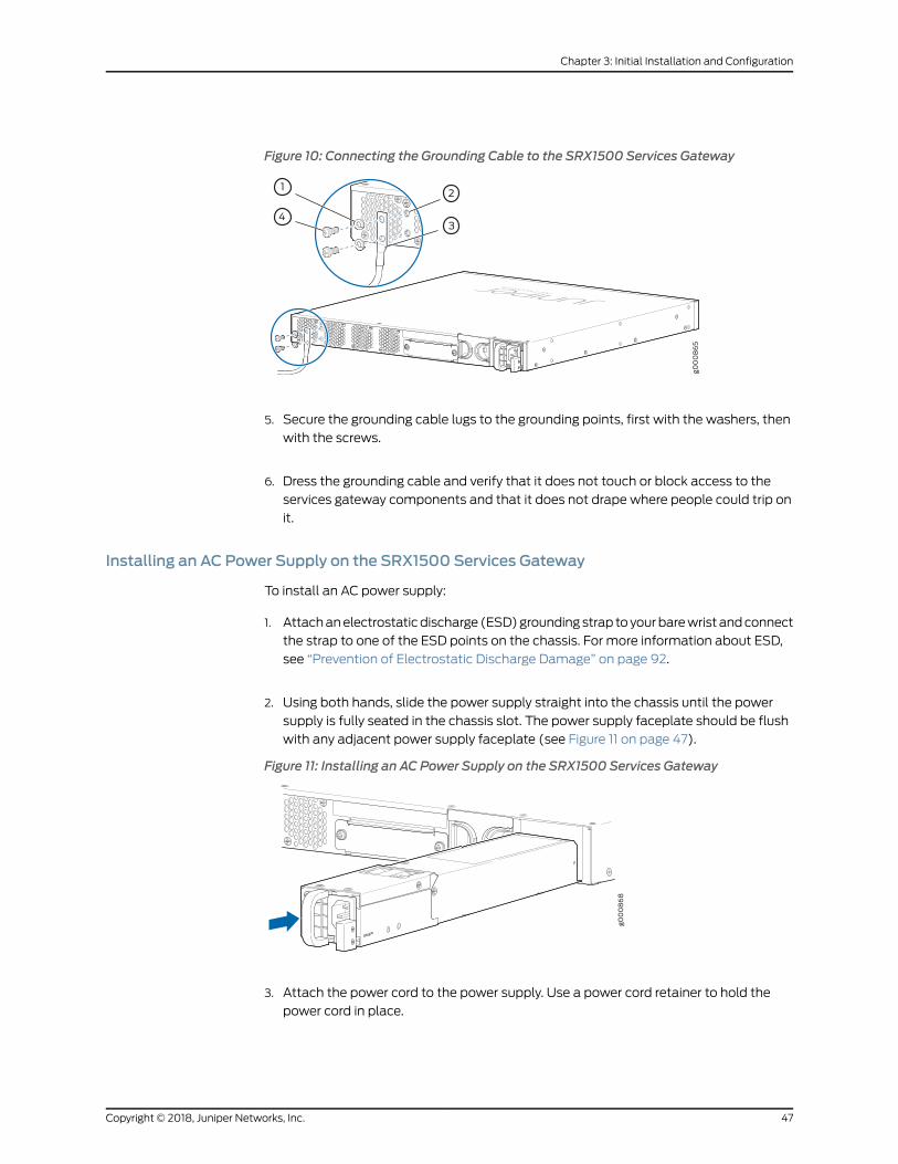
Figure 10: Connecting the Grounding Cable to the SRX1500 Services Gateway
5. Secure the grounding cable lugs to the grounding points, first with the washers, then
with the screws.
6. Dress the grounding cable and verify that it does not touch or block access to the
services gateway components and that it does not drape where people could trip on
it.
Installing an AC Power Supply on the SRX1500 Services Gateway
To install an AC power supply:
1. Attachanelectrostaticdischarge (ESD)groundingstrap toyourbarewrist andconnect
the strap to one of the ESD points on the chassis. For more information about ESD,
see “Prevention of Electrostatic Discharge Damage” on page 92.
2. Using both hands, slide the power supply straight into the chassis until the power
supply is fully seated in the chassis slot. The power supply faceplate should be flush
with any adjacent power supply faceplate (see Figure 11 on page 47).
Figure 11: Installing an AC Power Supply on the SRX1500 Services Gateway
3. Attach the power cord to the power supply. Use a power cord retainer to hold the
power cord in place.
47Copyright © 2018, Juniper Networks, Inc.
Chapter 3: Initial Installation and Configuration
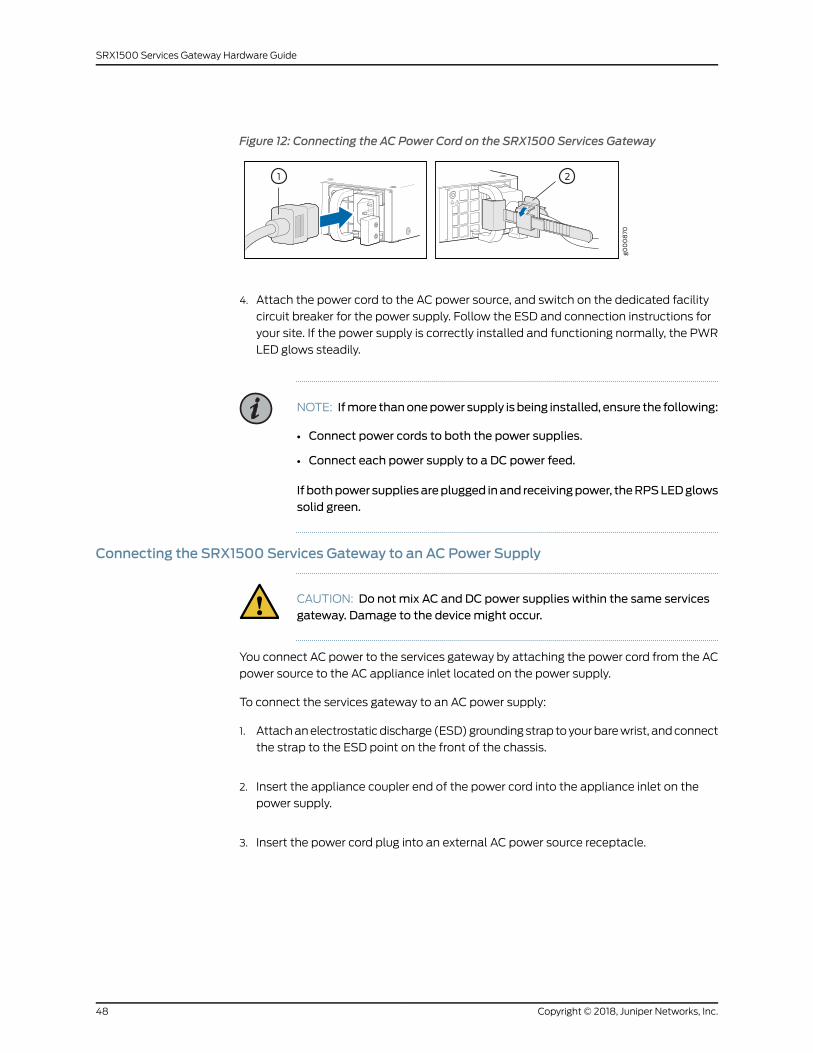
Figure 12: Connecting the AC Power Cord on the SRX1500 Services Gateway
4. Attach the power cord to the AC power source, and switch on the dedicated facility
circuit breaker for the power supply. Follow the ESD and connection instructions for
your site. If the power supply is correctly installed and functioning normally, the PWR
LED glows steadily.
NOTE: Ifmore thanonepower supply is being installed, ensure the following:
• Connect power cords to both the power supplies.
• Connect each power supply to a DC power feed.
If bothpower suppliesareplugged inand receivingpower, theRPSLEDglowssolid green.
Connecting the SRX1500 Services Gateway to an AC Power Supply
CAUTION: Do notmix AC and DC power supplies within the same servicesgateway. Damage to the devicemight occur.
You connect AC power to the services gateway by attaching the power cord from the AC
power source to the AC appliance inlet located on the power supply.
To connect the services gateway to an AC power supply:
1. Attachanelectrostaticdischarge (ESD)groundingstrap toyourbarewrist, andconnect
the strap to the ESD point on the front of the chassis.
2. Insert the appliance coupler end of the power cord into the appliance inlet on the
power supply.
3. Insert the power cord plug into an external AC power source receptacle.
Copyright © 2018, Juniper Networks, Inc.48
SRX1500 Services Gateway Hardware Guide

NOTE: Each power supply must be connected to a dedicated AC powerfeed and a dedicated external circuit breaker. We recommend that youuse a 15 A (250 VAC)minimum, or as permitted by local code.
4. Dress the power cord appropriately. Verify that the power cord does not block the air
exhaust and access to services gateway components or drape where people could
trip on it.
NOTE: The services gatewaymust be connected to earth ground duringnormal operation. The protective earthing terminal on the side of the chassisis provided to connect the services gateway to ground.
CAUTION: Werecommendusinga surgeprotector for thepower connection.
Installing a DC Power Supply on the SRX1500 Services Gateway
To install a DC power supply:
1. Ensure that the voltage across the DC power source cable leads is 0 V and that there
is no chance that the cable leads might become active during installation. To ensure
that all power is off, locate the circuit breaker on the panel board that services the DC
circuit, switch the circuit breaker to the OFF position (O), and tape the switch handle
of the circuit breaker in the OFF position.
2. Attachanelectrostaticdischarge (ESD)groundingstrap toyourbarewrist andconnect
the strap to one of the ESD points on the chassis. For more information about ESD,
see “Prevention of Electrostatic Discharge Damage” on page 92.
3. Orient the power supply so that the locking lever is on the left as shown in
Figure 13 on page 49.
Figure 13: Installing a DC Power Supply on an SRX1500 Services Gateway
49Copyright © 2018, Juniper Networks, Inc.
Chapter 3: Initial Installation and Configuration
4. Using both hands, slide the power supply straight into the chassis until the power
supply is fully seated in the chassis slot. The power supply faceplate should be flush
with any adjacent power supply faceplate.
5. Tighten the captive screws on the lower edge of the power supply faceplate.
6. Remove the clear plastic cover protecting the terminal studs on the faceplate.
7. Verify that the DC power cables are correctly labeled before making connections to
thepower supply. In a typical powerdistribution schemewhere the return is connected
to chassis ground at the battery plant, you can use amultimeter to verify the ohm
output of the –48V and RTN DC cables to chassis ground. The cable with very large
resistance (indicating an open circuit) to chassis ground will be –48V and the cable
with very low resistance (indicating a closed circuit) to chassis ground will be RTN.
CAUTION: Youmust ensure that power connectionsmaintain the properpolarity. Thepower source cablesmight be labeled (+)and (–) to indicatetheir polarity. There is no standard color coding for DC power cables. Thecolor coding usedby the externalDCpower source at your site determinesthe color coding for the leads on the power cables that attach to theterminal studs on each power supply.
8. Using a number 2 Phillips screwdriver, remove the screws and square washers from
the terminal studs.
9. Secure each power cable lug to the terminal studs, first with the square washer, then
with the screw. Apply between 23 lb-in. (2.6 Nm) and 25 lb-in. (2.8 Nm) of torque to
each screw.
a. Attach the positive (+) DC source power cable lug to the RTN (return) terminal.
b. Attach the negative (–) DC source power cable lug to the –48V (input) terminal.
Copyright © 2018, Juniper Networks, Inc.50
SRX1500 Services Gateway Hardware Guide

Figure 14: Securing the Power Cables
10. Replace the clear plastic cover over the terminal studs on the faceplate.
11. Verify that the power cables are connected correctly, that they are not touching or
blocking access to services gateway components, and that they do not drape where
people could trip on them.
12. Remove the tape from the switch handle of the circuit breaker on the panel board
that services theDCcircuit andswitch thecircuit breaker to theONposition (|).Observe
the statusLEDson thepower supply faceplate. If thepower supply is correctly installed
and functioning normally, the POWER LED glows solid green on the services gateway
front panel.
NOTE: If more than one power supply is being installed, turn on all powersupplies at the same time.
If both power supplies are plugged in and receiving AC power, the RPS LEDglows solid green.
51Copyright © 2018, Juniper Networks, Inc.
Chapter 3: Initial Installation and Configuration

Connecting the SRX1500 Services Gateway to a DC Power Supply
You connect DC power to the services gateway by attaching power cables from the
external DC power sources to the terminal studs on the power supply faceplates.
WARNING: Tomeet safety and electromagnetic interference (EMI)requirements and to ensure proper operation, youmust properly ground theservices gateway chassis before connecting power. See “Connecting theSRX1500 Services Gateway Grounding Cable” on page 46 for instructions.
WARNING: Before performing the following procedure, ensure that power isremoved from theDC circuit. To ensure that all power is off, locate the circuitbreaker on the panel board that services the DC circuit, switch the circuitbreaker to the OFF position (0), and tape the switch handle of the circuitbreaker in the OFF position.
CAUTION: Do notmix AC and DC power supplies within the same servicesgateway. Damage to the services gatewaymight occur.
CAUTION: Before you connect power to the services gateway, a licensedelectricianmust attach appropriate cable lugs to the grounding and powercables that you use. A cable with an incorrectly attached lug can damagethe device (for example, by causing a short circuit).
To connect the DC source power cables to the services gateway for each power supply:
1. Switch off the dedicated facility circuit breakers. Ensure that the voltage across the
DC power source cable leads is 0 V and that there is no chance that the cable leads
might become active during installation.
2. Remove the clear plastic cover that protects the terminal studs on the faceplate.
3. Verify that the DC power cables are correctly labeled before making connections to
the power supply.
Ina typicalpowerdistributionschemewhere the return is connected tochassisground
at the battery plant, you can use amultimeter to verify the ohm output of the -48V
andRTNDC cables to chassis ground. The cablewith very large resistance (indicating
an open circuit) to chassis groundwill be -48V, and the cablewith very low resistance
(indicating a closed circuit) to chassis ground will be RTN.
Copyright © 2018, Juniper Networks, Inc.52
SRX1500 Services Gateway Hardware Guide
CAUTION: Youmust ensure that power connectionsmaintain the properpolarity. The power source cablesmight be labeled (+)and (–) to indicate
their polarity. There is no standard color coding for DC power cables. Thecolor coding usedby the externalDCpower source at your site determinesthe color coding for the leads on the power cables that attach to theterminal studs on each power supply.
4. Remove the screws and square washers from the terminals, using a Phillips (+)
screwdriver, number 2.
5. Secure eachpower cable lug to the terminalswith the squarewashers and the screws.
Apply between 23 in.-lb (2.6 Nm) and 25 in.-lb (2.8 Nm) of torque to each screw.
• Secure each positive (+) DC source power cable lug to a RTN (return) terminal.
• Secure each negative (–) DC source power cable lug to a -48V (input) terminal.
6. Replace the clear plastic cover over the terminal studs on the faceplate.
7. Verify that the power cables are connected correctly, that they are not touching or
blocking access to services gateway components, and they do not cause a tripping
hazard.
8. Repeat Steps 1 through 7 for the second power supply, if you are installing one.
NOTE: If power is lost to the services gateway, the Power-On/Power-Offstate is retained. For example, if the services gateway loses power while thedevice is on, when power returns, the device will still be in the On state.
Powering On the SRX1500 Services Gateway
To power on the services gateway:
1. Ensure that you have connected the power supply to the device.
2. Insert the plug of the power supply adapter into anACor DCpower source receptacle.
a. Using AC power supply—Insert the appliance coupler end of the power cord into
the appliance inlet on the power supply and the power cord plug into an external
AC power source receptacle.
b. UsingDCpower supply—Connect DCpower cables to theA+andA- terminals and
the other ends to an external DC power source. If you have two DC power sources
and wish to deploy A/B feed redundancy for the services gateway, also connect
DC power cables to the B+ and B- terminals and the other ends to an external DC
power source.
53Copyright © 2018, Juniper Networks, Inc.
Chapter 3: Initial Installation and Configuration

CAUTION: Youmust ensure that power connectionsmaintain theproper polarity. The power source cablesmight be labeled (+) and (–)to indicate theirpolarity.There isnostandardcolorcoding forDCpowercables. The color coding used by the external DC power source at yoursite determines the color coding for the leads on the power cables thatattach to the terminals on the power supply.
3. Turn on the power to the AC or DC power receptacle.
The device starts automatically as the power supply completes its startup sequence.
The PWR LED (on the front panel of the chassis) lights up during startup and remains
solid when the services gateway is operating normally.
Powering Off the SRX1500 Services Gateway
To power off the device, press the Power button on the front of the device and hold it for
10 seconds. To remove power completely from the services gateway, unplug the AC
power cord or DC power supply cable.
NOTE: Graceful shutdown is not supported on the SRX1500 ServicesGateway.
After powering off a power supply, wait at least 60 seconds before turning it back on.
After powering on a power supply, wait at least 10 seconds before turning it off.
When the system is completely powered off and you turn on the power supply, the
services gateway starts as the power supply completes its startup sequence. If the
services gateway finishes starting and you need to power off the systemagain, first issue
the request system halt command.
NOTE: The fans in the power supply continue to rotate even after you poweroff the SRX1500 Services Gateway. To stop the fans, remove the power cordfrom the power supply. The fans stop in a few seconds.
After apower supply is turnedon, it can takeup to60seconds for status indicators—such
as the POWER LED (on the front panel of the chassis) and the show chassis command
display—to indicate that the power supply is functioning normally. Ignore error indicators
that appear during the first 60 seconds.
Connecting the SRX1500 to External Devices
• Required Tools and Parts for Connecting the SRX1500 Services Gateway on page 55
• Connecting the SRX1500 Services Gateway to a Network for Out-of-Band
Management on page 55
• Connecting the SRX1500 Services Gateway to a Management Console on page 55
Copyright © 2018, Juniper Networks, Inc.54
SRX1500 Services Gateway Hardware Guide
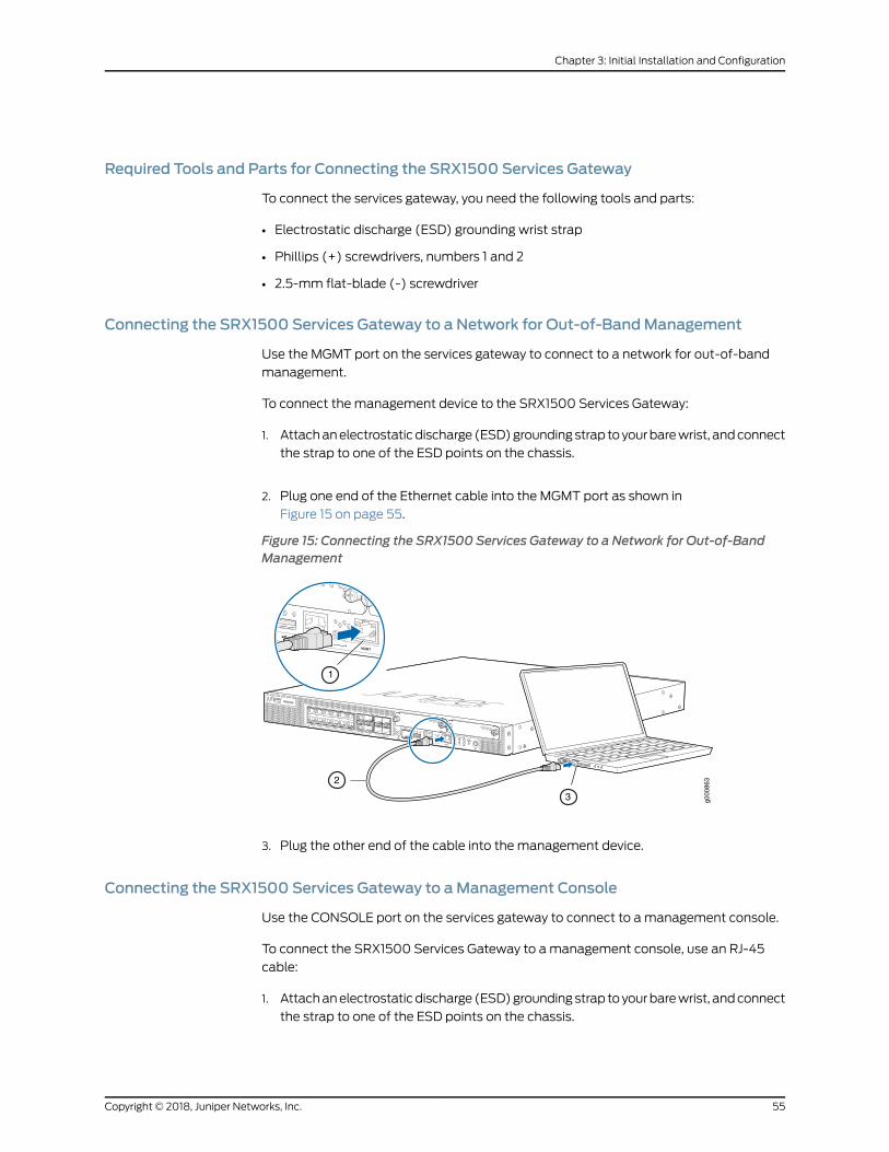
Required Tools and Parts for Connecting the SRX1500 Services Gateway
To connect the services gateway, you need the following tools and parts:
• Electrostatic discharge (ESD) grounding wrist strap
• Phillips (+) screwdrivers, numbers 1 and 2
• 2.5-mm flat-blade (-) screwdriver
Connecting the SRX1500 Services Gateway to a Network for Out-of-BandManagement
Use the MGMT port on the services gateway to connect to a network for out-of-band
management.
To connect the management device to the SRX1500 Services Gateway:
1. Attachanelectrostaticdischarge (ESD)groundingstrap toyourbarewrist, andconnect
the strap to one of the ESD points on the chassis.
2. Plug one end of the Ethernet cable into the MGMT port as shown in
Figure 15 on page 55.
Figure 15: Connecting the SRX1500 Services Gateway to a Network for Out-of-BandManagement
g000
863
1
2
3
3. Plug the other end of the cable into the management device.
Connecting the SRX1500 Services Gateway to aManagement Console
Use the CONSOLE port on the services gateway to connect to amanagement console.
To connect the SRX1500 Services Gateway to amanagement console, use an RJ-45
cable:
1. Attachanelectrostaticdischarge (ESD)groundingstrap toyourbarewrist, andconnect
the strap to one of the ESD points on the chassis.
55Copyright © 2018, Juniper Networks, Inc.
Chapter 3: Initial Installation and Configuration
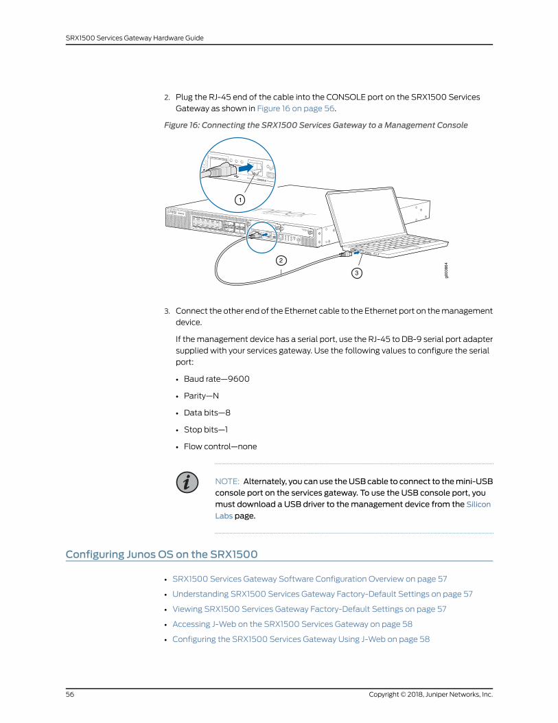
2. Plug the RJ-45 end of the cable into the CONSOLE port on the SRX1500 Services
Gateway as shown in Figure 16 on page 56.
Figure 16: Connecting the SRX1500 Services Gateway to aManagement Console
g000
864
1
2
3
3. Connect the other end of the Ethernet cable to the Ethernet port on themanagement
device.
If themanagement device has a serial port, use the RJ-45 to DB-9 serial port adapter
supplied with your services gateway. Use the following values to configure the serial
port:
• Baud rate—9600
• Parity—N
• Data bits—8
• Stop bits—1
• Flow control—none
NOTE: Alternately, you can use theUSBcable to connect to themini-USBconsole port on the services gateway. To use the USB console port, youmust download a USB driver to themanagement device from the Silicon
Labs page.
Configuring Junos OS on the SRX1500
• SRX1500 Services Gateway Software Configuration Overview on page 57
• Understanding SRX1500 Services Gateway Factory-Default Settings on page 57
• Viewing SRX1500 Services Gateway Factory-Default Settings on page 57
• Accessing J-Web on the SRX1500 Services Gateway on page 58
• Configuring the SRX1500 Services Gateway Using J-Web on page 58
Copyright © 2018, Juniper Networks, Inc.56
SRX1500 Services Gateway Hardware Guide
• Accessing the CLI on the SRX1500 Services Gateway on page 62
• Connecting to the SRX1500 Services Gateway from the CLI Remotely on page 63
• Configuring the SRX1500 Services Gateway Using the CLI on page 63
SRX1500 Services Gateway Software Configuration Overview
The SRX1500 Services Gateway is shipped with Junos OS preinstalled and ready to be
configured when the services gateway is powered on. If you are setting up the services
gateway for the first time, use the command-line interface (CLI) to perform the initial
configuration.
Gather the following information before configuring the services gateway:
• Root authentication
• IP address of the management interface
• Default route
Understanding SRX1500 Services Gateway Factory-Default Settings
Your servicesgatewaycomesconfiguredwitha factory-default configuration. Thedefault
configuration includes the following security configuration:
• Two security zones are created: trust and untrust.
• Interface ge-0/0/0 is in the untrust zone, while interfaces ge-0/0/1 through ge-0/0/3
are in the trust zone.
• A security policy is created that permits outbound traffic from the trust zone to the
untrust zone.
• Source Network Address Translation (NAT) is configured on the trust zone.
If the current active configuration fails, you can use the load factory-default command
to revert to the factory-default configuration.
Viewing SRX1500 Services Gateway Factory-Default Settings
To view the factory-default configuration of the services gateway using the CLI:
1. Log in as the root user and provide your credentials.
2. View the list of default config files:
root@srx1500>file list /etc/config
3. View the required default config file.
root@srx1500> file show /etc/config/<config file name>
57Copyright © 2018, Juniper Networks, Inc.
Chapter 3: Initial Installation and Configuration

Accessing J-Web on the SRX1500 Services Gateway
The J-Web interface is aWeb-based graphical interface that allows you to operate a
services gatewaywithout commands. Before youcanuse J-Web to configure your device,
youmust access the CLI to perform the initial configuration.
NOTE: Toaccess the J-Web interface, yourmanagement device requires oneof the following supported browsers:
• Microsoft Internet Explorer version 8.0, 9.0, or 10.0
• Mozilla Firefox version 23+
• Google Chrome version 28+
To access J-Web:
1. Open aWeb browser on themanagement device and enter the device management
IP address in the address field.
2. Specify the default username as root and enter the password.
Configuring the SRX1500 Services Gateway Using J-Web
• ConfiguringRootAuthenticationandtheManagement Interface fromtheCLIonpage58
• Configuring Interfaces, Zones, and Policies with J-Web on page 59
Configuring Root Authentication and theManagement Interface from the CLI
Before you can use J-Web to configure your device, youmust access the CLI to perform
the initial configuration.
To configure root authentication and themanagement interface:
1. Log in as root. There is no password.
2. Start the CLI and enter configuration mode.
root@% cliroot@>configureroot@#
3. Set the root authentication password by entering a cleartext password, an encrypted
password, or an SSH public key string (DSA or RSA).
[edit]root@# set system root-authentication plain-text-passwordNew password: passwordRetype new password: password
Copyright © 2018, Juniper Networks, Inc.58
SRX1500 Services Gateway Hardware Guide
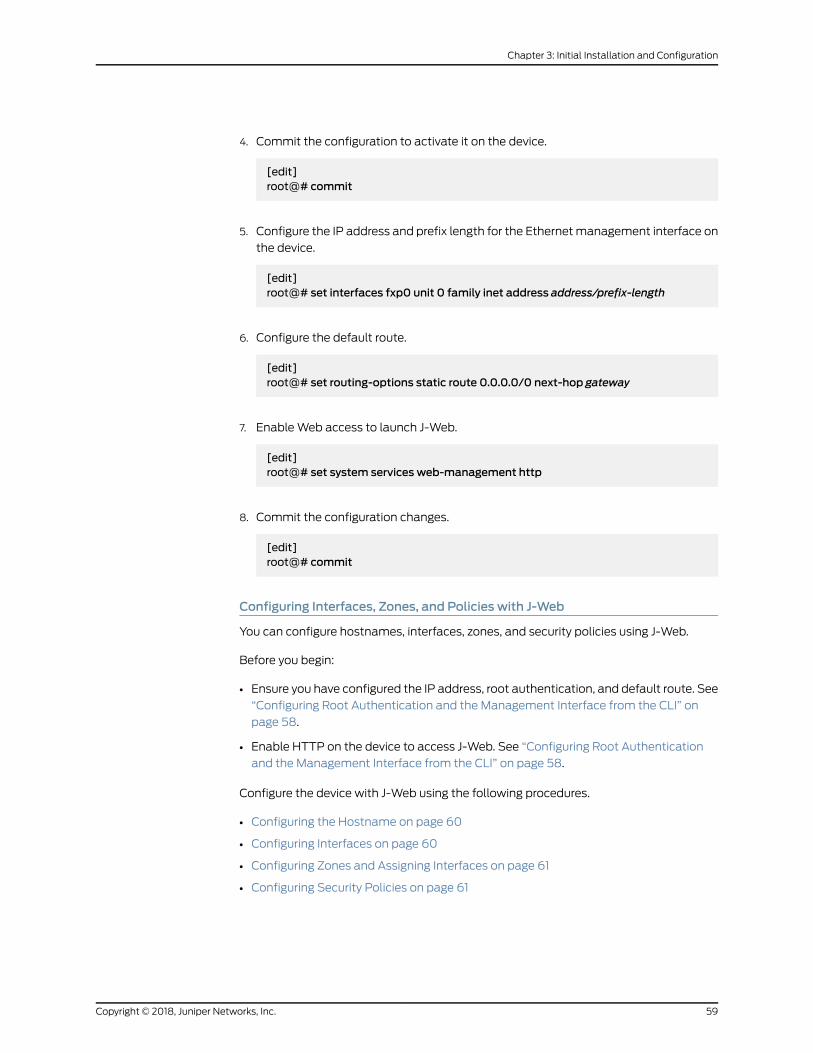
4. Commit the configuration to activate it on the device.
[edit]root@# commit
5. Configure the IP address and prefix length for the Ethernetmanagement interface on
the device.
[edit]root@# set interfaces fxp0 unit 0 family inet address address/prefix-length
6. Configure the default route.
[edit]root@# set routing-options static route 0.0.0.0/0 next-hop gateway
7. EnableWeb access to launch J-Web.
[edit]root@# set system services web-management http
8. Commit the configuration changes.
[edit]root@# commit
Configuring Interfaces, Zones, and Policies with J-Web
You can configure hostnames, interfaces, zones, and security policies using J-Web.
Before you begin:
• Ensure you have configured the IP address, root authentication, and default route. See
“Configuring Root Authentication and the Management Interface from the CLI” on
page 58.
• Enable HTTP on the device to access J-Web. See “Configuring Root Authentication
and the Management Interface from the CLI” on page 58.
Configure the device with J-Web using the following procedures.
• Configuring the Hostname on page 60
• Configuring Interfaces on page 60
• Configuring Zones and Assigning Interfaces on page 61
• Configuring Security Policies on page 61
59Copyright © 2018, Juniper Networks, Inc.
Chapter 3: Initial Installation and Configuration
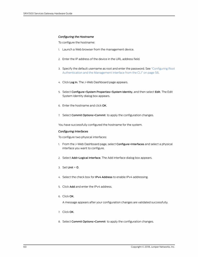
Configuring the Hostname
To configure the hostname:
1. Launch aWeb browser from themanagement device.
2. Enter the IP address of the device in the URL address field.
3. Specify the default username as root and enter the password. See “Configuring Root
Authentication and the Management Interface from the CLI” on page 58.
4. Click Log In. The J-Web Dashboard page appears.
5. Select Configure>SystemProperties>System Identity, and then select Edit. The Edit
System Identity dialog box appears.
6. Enter the hostname and clickOK.
7. Select Commit Options>Commit to apply the configuration changes.
You have successfully configured the hostname for the system.
Configuring Interfaces
To configure two physical interfaces:
1. From the J-Web Dashboard page, select Configure>Interfaces and select a physical
interface you want to configure.
2. Select Add>Logical Interface. The Add interface dialog box appears.
3. Set Unit = 0.
4. Select the check box for IPv4 Address to enable IPv4 addressing.
5. Click Add and enter the IPv4 address.
6. ClickOK.
A message appears after your configuration changes are validated successfully.
7. ClickOK.
8. Select Commit Options>Commit to apply the configuration changes.
Copyright © 2018, Juniper Networks, Inc.60
SRX1500 Services Gateway Hardware Guide
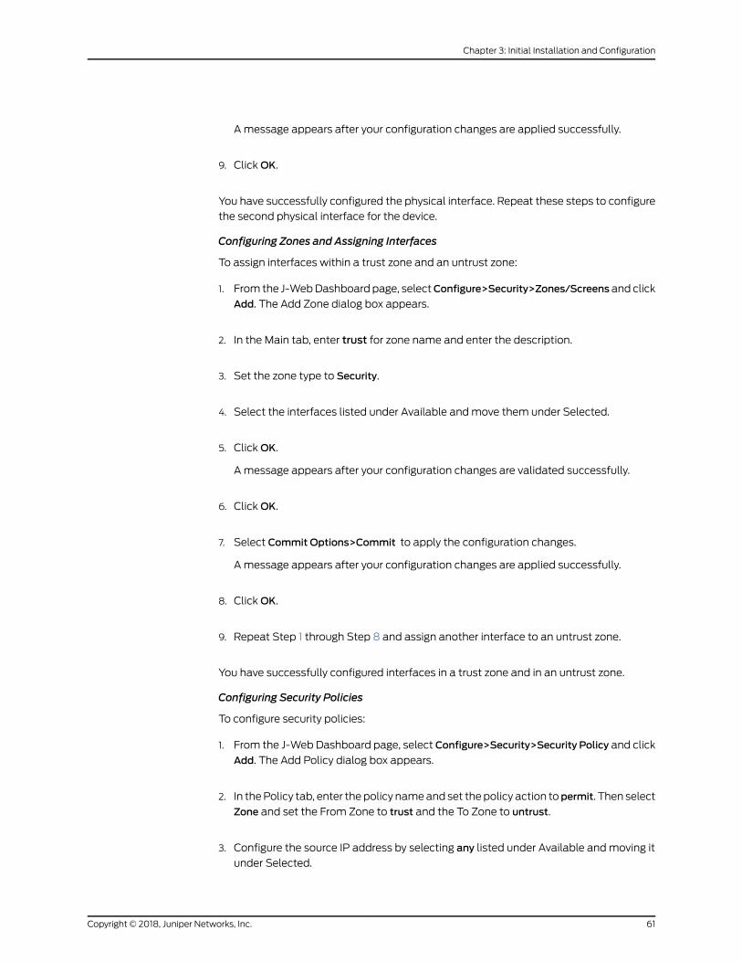
Amessage appears after your configuration changes are applied successfully.
9. ClickOK.
You have successfully configured the physical interface. Repeat these steps to configure
the second physical interface for the device.
Configuring Zones and Assigning Interfaces
To assign interfaces within a trust zone and an untrust zone:
1. From the J-WebDashboard page, selectConfigure>Security>Zones/Screens and click
Add. The Add Zone dialog box appears.
2. In the Main tab, enter trust for zone name and enter the description.
3. Set the zone type to Security.
4. Select the interfaces listed under Available andmove them under Selected.
5. ClickOK.
A message appears after your configuration changes are validated successfully.
6. ClickOK.
7. Select Commit Options>Commit to apply the configuration changes.
A message appears after your configuration changes are applied successfully.
8. ClickOK.
9. Repeat Step 1 through Step 8 and assign another interface to an untrust zone.
You have successfully configured interfaces in a trust zone and in an untrust zone.
Configuring Security Policies
To configure security policies:
1. From the J-Web Dashboard page, select Configure>Security>Security Policy and click
Add. The Add Policy dialog box appears.
2. In thePolicy tab, enter thepolicy nameand set thepolicy action topermit. Then select
Zone and set the From Zone to trust and the To Zone to untrust.
3. Configure the source IP address by selecting any listed under Available andmoving it
under Selected.
61Copyright © 2018, Juniper Networks, Inc.
Chapter 3: Initial Installation and Configuration
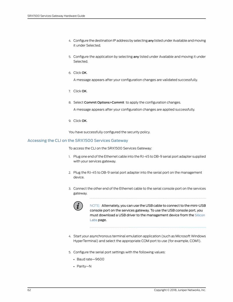
4. Configure thedestination IPaddressbyselectingany listedunderAvailableandmoving
it under Selected.
5. Configure the application by selecting any listed under Available andmoving it under
Selected.
6. ClickOK.
A message appears after your configuration changes are validated successfully.
7. ClickOK.
8. Select Commit Options>Commit to apply the configuration changes.
A message appears after your configuration changes are applied successfully.
9. ClickOK.
You have successfully configured the security policy.
Accessing the CLI on the SRX1500 Services Gateway
To access the CLI on the SRX1500 Services Gateway:
1. Plug one endof the Ethernet cable into theRJ-45 toDB-9 serial port adapter supplied
with your services gateway.
2. Plug the RJ-45 to DB-9 serial port adapter into the serial port on the management
device.
3. Connect the other end of the Ethernet cable to the serial console port on the services
gateway.
NOTE: Alternately, you can use theUSBcable to connect to themini-USBconsole port on the services gateway. To use the USB console port, youmust download a USB driver to themanagement device from the Silicon
Labs page.
4. Start your asynchronous terminal emulation application (such asMicrosoftWindows
HyperTerminal) and select the appropriate COM port to use (for example, COM1).
5. Configure the serial port settings with the following values:
• Baud rate—9600
• Parity—N
Copyright © 2018, Juniper Networks, Inc.62
SRX1500 Services Gateway Hardware Guide
• Data bits—8
• Stop bits—1
• Flow control—none
6. Power on the services gateway. You can start performing initial software configuration
on the services gateway after the device is up.
Connecting to the SRX1500 Services Gateway from the CLI Remotely
To connect the services gateway to a network for out-of-bandmanagement:
1. Plug one end of an Ethernet cable with RJ-45 connectors into the MGMT port on the
front panel of the services gateway.
2. Plug the other end of the cable into the management device.
Configuring the SRX1500 Services Gateway Using the CLI
This sample procedure explains how you can create an initial configuration using CLI
commands to connect the SRX1500 Services Gateway to the network.
1. Verify that the device is powered on.
2. Log in as the root user. Do not enter a password.
3. Start the CLI.
root@%cli
root>
4. Enter configuration mode.
configure
[edit]
root#
5. Set the root authentication password by entering a cleartext password, an encrypted
password, or an SSH public key string (DSA or RSA).
[edit]
root# set system root-authentication plain-text-password
New password: password
Retype new password: password
63Copyright © 2018, Juniper Networks, Inc.
Chapter 3: Initial Installation and Configuration
6. Configure an administrator account on the device.When you are prompted, enter the
password for the administrator account.
[edit]
root# set system login user admin class super-user authentication plain-text-password
New password: password
Retype new password: password
7. Commit the configuration to activate it on the services gateway.
[edit]
root# commit
8. Log in as the administrative user you configured in Step 6.
9. Configure the name of the services gateway. If the name includes spaces, enclose the
name in quotation marks (“ ”).
configure
[edit]
admin# set system host-name host-name
10. Configure the IP address andprefix length for the services gatewayEthernet interface.
[edit]
admin# set interfaces fxp0 unit 0 family inet address address/prefix-length
11. Configure the traffic interface.
[edit]
admin# set interfaces ge-0/0/0 unit 0 family inet address address/prefix-length
admin# set interfaces ge-0/0/1 unit 0 family inet address address/prefix-length
NOTE: The ge-0/0/0 interface is for the LAN, and the ge-0/0/1 interfaceis for the ISP.
12. Configure the default route.
[edit]
admin# set routing-options static route 0.0.0.0/0 next-hop gateway
13. Configure basic security zones and bind them to traffic interfaces.
Copyright © 2018, Juniper Networks, Inc.64
SRX1500 Services Gateway Hardware Guide
[edit]
admin# set security zones security-zone untrust interfaces ge-0/0/0
admin# set security zones security-zone trust interfaces ge-0/0/1
14. Configure basic security policies.
[edit]
admin# set security policies from-zone trust to-zone untrust policy policy-namematchsource-address any destination-address any application any
admin# set security policies from-zone trust to-zone untrust policy policy-name then permit
admin# set security policies from-zone untrust to-zone trust policy policy-namematchsource-address any destination-address any application any
admin# set security policies from-zone untrust to-zone trust policy policy-name then permit
NOTE: The actual configuration of the policies depends on yourrequirements.
15. Check the configuration for validity.
[edit]
admin# commit check
configuration check succeeds
16. Commit the configuration to activate it on the services gateway.
[edit]
admin# commit
commit complete
17. Optionally, display the configuration to verify that it is correct.
NOTE: This is a sample output. The actual output might vary dependingon your configuration requirements.
admin@# show
system { host-name forge02; root-authentication { encrypted-password "$1$ZUlES4dp$OUwWo1g7cLoV/aMWpHUnC/"; ## SECRET-DATA
65Copyright © 2018, Juniper Networks, Inc.
Chapter 3: Initial Installation and Configuration

}
services { ssh; web-management { http { interface fxp0.0;
} } } syslog { user * { any emergency; } file messages { any any; authorization info; } file interactive-commands { interactive-commands any; } }
security { policies { from-zone trust to-zone untrust { policy trust-pol { match { source-address any; destinataion-address any; application any; } then { permit; } } }
from-zone untrust to-zone trust { policy untrust-pol { match { source-address any; destinataion-address any; application any; } then { permit; } } } }
zones { security-zone trust { interfaces { ge-0/0/0.0; }
Copyright © 2018, Juniper Networks, Inc.66
SRX1500 Services Gateway Hardware Guide

} security-zone untrust { interfaces { ge-0/0/1.0; } } } } interfaces { ge-0/0/0 { unit 0 { family inet { address 9.0.0.254/8; } } } ge-0/0/1 { unit 0 { family inet { address 10.0.0.254/8; } } } fxp0 { unit 0 { family inet { address 10.157.80.85/19; } } } }
18. Commit the configuration to activate it on the services gateway.
[edit]admin# commit
19. Optionally, configure additional properties by adding the necessary configuration
statements. Then commit the changes to activate them on the services gateway.
[edit]admin# commit
20.When you have finished configuring the services gateway, exit configuration mode.
[edit]admin# exitadmin>
NOTE: Toaccess thedeviceusing J-Webfor the first time,enter configurationmode in the CLI, and set themanagement option using the command setsystem services web-management http.
67Copyright © 2018, Juniper Networks, Inc.
Chapter 3: Initial Installation and Configuration
Launch aWeb browser from themanagement device and access the services gateway
using theURLhttp://<devicemanagement IPaddress>.The J-Web loginpage isdisplayed.
This indicates that you have successfully completed the initial configuration, and your
SRX1500 Services Gateway is ready for use.
Copyright © 2018, Juniper Networks, Inc.68
SRX1500 Services Gateway Hardware Guide
CHAPTER 4
Maintaining Components
• Maintaining the SRX1500 Components on page 69
• Maintaining the SRX1500 Power System on page 69
Maintaining the SRX1500 Components
• Required Tools and Parts for Maintaining the SRX1500 Services Gateway on page 69
• Routine Maintenance Procedures for the SRX1500 Services Gateway on page 69
Required Tools and Parts for Maintaining the SRX1500 Services Gateway
The following tools and parts are required to maintain the hardware components of the
services gateway:
• Electrostatic bag or antistatic mat
• Electrostatic discharge (ESD) grounding wrist strap
• Flat-blade screw-blade screwdriver, approximately 1/8 in. (3 mm)
• Phillips (+) screwdrivers, numbers 1 and 2
RoutineMaintenance Procedures for the SRX1500 Services Gateway
For optimum performance of the services gateway, perform the following preventive
maintenance procedures regularly:
• Inspect the installation site for moisture, loose wires or cables, and excessive dust.
• Make sure that airflow is unobstructed around the services gateway and into the air
intake vents.
• Check the status LEDs on the front panel of the services gateway.
Maintaining the SRX1500 Power System
• Maintaining the SRX1500 Services Gateway Power Supply on page 70
• Required Tools and Parts for Replacing the SRX1500 Services Gateway
Components on page 70
69Copyright © 2018, Juniper Networks, Inc.
• Replacing an AC Power Supply on the SRX1500 Services Gateway on page 70
• Replacing a DC Power Supply on the SRX1500 Services Gateway on page 72
Maintaining the SRX1500 Services Gateway Power Supply
Tomaintain the power supplies of the services gateway:
• Makesure thatall powerandgroundingcablesarearrangedso that theydonotobstruct
access to other services gateway components.
• Routinely check the PWR LED on the front panel. If this LED is solid green, the power
supplies are functioning normally.
• Periodically inspect the site to ensure that the grounding and power cables connected
to the servicesgatewayare securely inplaceand that there is nomoistureaccumulating
near the services gateway.
Required Tools and Parts for Replacing the SRX1500 Services Gateway Components
The following tools and parts are required to replace hardware components.
• 3/8 in. nut driver or pliers
• Blank panels (if component is not reinstalled)
• Electrostatic bag or antistatic mat
• Electrostatic discharge (ESD) grounding wrist strap
• Flat-blade (–) screwdriver
• Phillips (+) screwdrivers, numbers 1 and 2
• Wire cutters
Replacing an AC Power Supply on the SRX1500 Services Gateway
• Disconnecting an AC Power Cord from the SRX1500 Services Gateway on page 70
• Removing an AC Power Supply from the SRX1500 Services Gateway on page 71
Disconnecting an AC Power Cord from the SRX1500 Services Gateway
WARNING: BeforeworkingonanAC-powereddeviceor nearpower supplies,unplug the power cord.
To disconnect the AC power cord:
1. Unplug the power cord from the power source receptacle.
2. Attachanelectrostaticdischarge (ESD)groundingstrap toyourbarewrist andconnect
the strap to one of the ESD points on the chassis. For more information about ESD,
see “Prevention of Electrostatic Discharge Damage” on page 92.
Copyright © 2018, Juniper Networks, Inc.70
SRX1500 Services Gateway Hardware Guide
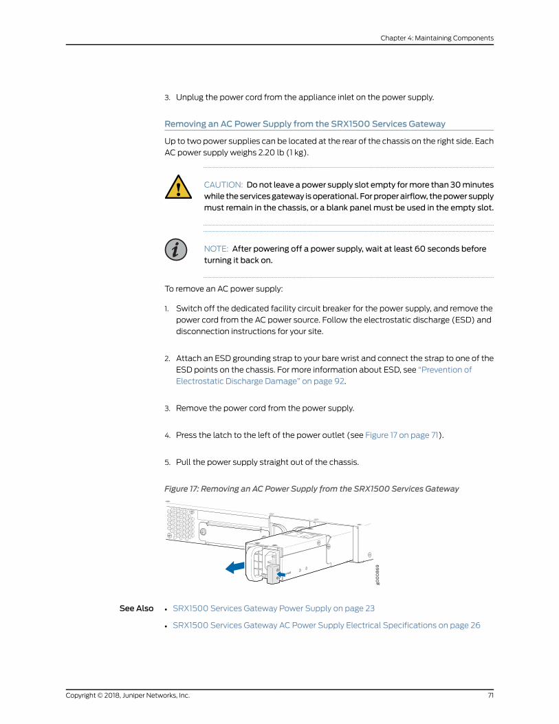
3. Unplug the power cord from the appliance inlet on the power supply.
Removing an AC Power Supply from the SRX1500 Services Gateway
Up to two power supplies can be located at the rear of the chassis on the right side. Each
AC power supply weighs 2.20 lb (1 kg).
CAUTION: Donot leave a power supply slot empty formore than 30minuteswhile theservicesgateway isoperational. Forproperairflow, thepowersupplymust remain in the chassis, or a blank panel must be used in the empty slot.
NOTE: After powering off a power supply, wait at least 60 seconds beforeturning it back on.
To remove an AC power supply:
1. Switch off the dedicated facility circuit breaker for the power supply, and remove the
power cord from the AC power source. Follow the electrostatic discharge (ESD) and
disconnection instructions for your site.
2. Attach an ESD grounding strap to your bare wrist and connect the strap to one of the
ESD points on the chassis. For more information about ESD, see “Prevention of
Electrostatic Discharge Damage” on page 92.
3. Remove the power cord from the power supply.
4. Press the latch to the left of the power outlet (see Figure 17 on page 71).
5. Pull the power supply straight out of the chassis.
Figure 17: Removing an AC Power Supply from the SRX1500 Services Gateway
See Also SRX1500 Services Gateway Power Supply on page 23•
• SRX1500 Services Gateway AC Power Supply Electrical Specifications on page 26
71Copyright © 2018, Juniper Networks, Inc.
Chapter 4: Maintaining Components
Replacing a DC Power Supply on the SRX1500 Services Gateway
• Removing a DC Power Supply Cable from the SRX1500 Services Gateway on page 72
• Removing a DC Power Supply on the SRX1500 Services Gateway on page 72
Removing a DC Power Supply Cable from the SRX1500 Services Gateway
To remove a power supply cable connected to a DC power supply:
1. Attachanelectrostaticdischarge (ESD)groundingstrap toyourbarewrist andconnect
the strap to an approved site ESD grounding point. For more information about ESD,
see “Prevention of Electrostatic Discharge Damage” on page 92.
2. Switch off the external circuit breakers for all the cables attached to thepower supply.
Make sure that the voltage across the DC power source cable leads is 0 V and that
there is no chance that the cables might become active during the removal process.
3. Remove the power cable from the DC power source.
4. Attach an ESD grounding strap to your bare wrist and connect the strap to one of the
ESD points on the chassis. For more information about ESD, see “Prevention of
Electrostatic Discharge Damage” on page 92.
5. Make sure the cable is not touching or in thewayof any services gateway components
and that it does not drape where people could trip on it.
6. Remove the clear plastic cover protecting the terminal studs on the faceplate.
7. Attach the power cable to the DC power source.
8. Verify that the DC source power cabling is correct. If the power cable is correctly
installed and the power supply is functioning normally, the POWER LED on the front
panel glows solid green.
Removing a DC Power Supply on the SRX1500 Services Gateway
Up to two power supplies can be located at the rear of the chassis on the right side. Each
DC power supply weighs approximately 2.20 lbs (1 kg).
CAUTION: Donot leave a power supply slot empty formore than 30minuteswhile theservicesgateway isoperational. Forproperairflow, thepowersupplymust remain in the chassis, or a blank panel must be used in the empty slot.
Copyright © 2018, Juniper Networks, Inc.72
SRX1500 Services Gateway Hardware Guide
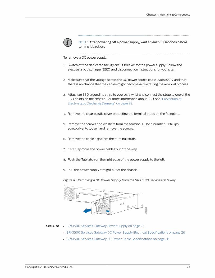
NOTE: After powering off a power supply, wait at least 60 seconds beforeturning it back on.
To remove a DC power supply:
1. Switch off the dedicated facility circuit breaker for the power supply. Follow the
electrostatic discharge (ESD) and disconnection instructions for your site.
2. Make sure that the voltage across the DC power source cable leads is 0 V and that
there is no chance that the cables might become active during the removal process.
3. Attach an ESD grounding strap to your bare wrist and connect the strap to one of the
ESD points on the chassis. For more information about ESD, see “Prevention of
Electrostatic Discharge Damage” on page 92.
4. Remove the clear plastic cover protecting the terminal studs on the faceplate.
5. Remove the screws and washers from the terminals. Use a number 2 Phillips
screwdriver to loosen and remove the screws.
6. Remove the cable lugs from the terminal studs.
7. Carefully move the power cables out of the way.
8. Push the Tab latch on the right edge of the power supply to the left.
9. Pull the power supply straight out of the chassis.
Figure 18: Removing a DC Power Supply from the SRX1500 Services Gateway
See Also • SRX1500 Services Gateway Power Supply on page 23
• SRX1500 Services Gateway DC Power Supply Electrical Specifications on page 26
• SRX1500 Services Gateway DC Power Cable Specifications on page 26
73Copyright © 2018, Juniper Networks, Inc.
Chapter 4: Maintaining Components

Copyright © 2018, Juniper Networks, Inc.74
SRX1500 Services Gateway Hardware Guide
CHAPTER 5
Troubleshooting Hardware
• Troubleshooting the SRX1500 on page 75
Troubleshooting the SRX1500
• Troubleshooting Resources for the SRX1500 Services Gateway Overview on page 75
• Troubleshooting Chassis and Interface AlarmMessages on the SRX1500 Services
Gateway on page 75
• Troubleshooting the Power System on the SRX1500 Services Gateway on page 77
• Using the RESET CONFIG Button on the SRX1500 Services Gateway on page 78
• Changing the RESET CONFIG Button Behavior on the SRX1500 Services
Gateway on page 79
Troubleshooting Resources for the SRX1500 Services Gateway Overview
To troubleshoot a services gateway, you use the Junos OS command-line interface (CLI)
and LEDs on the components:
• LEDs—When the services gateway detects an alarm condition, the alarm LED on the
interfaces glows red or yellow.
• CLI—The CLI is the primary tool for controlling and troubleshooting hardware, Junos
OS, and network connectivity. Use the CLI to display more information about alarms.
CLI commands display information about network connectivity derived from the ping
and traceroute utilities. For information about using the CLI to troubleshoot Junos OS,
see the appropriate Junos OS configuration guide.
• JTAC—If you need assistance during troubleshooting, you can contact the Juniper
Networks Technical Assistance Center (JTAC) by using theWeb or by telephone. If
you encounter software problems, or problems with hardware components not
discussed here, contact JTAC.
Troubleshooting Chassis and Interface AlarmMessages on the SRX1500 Services Gateway
Problem Description:When the services gateway detects an alarm condition, the alarm LED on
the interfaces glows red or yellow on the front panel as appropriate. To view amore
detailed description of the alarm cause, issue the show chassis alarms command.
75Copyright © 2018, Juniper Networks, Inc.
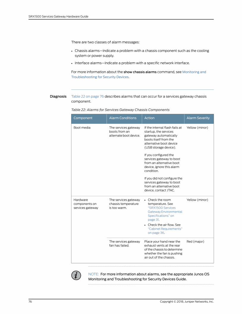
There are two classes of alarmmessages:
• Chassis alarms—Indicate a problemwith a chassis component such as the cooling
system or power supply.
• Interface alarms—Indicate a problemwith a specific network interface.
For more information about the show chassis alarms command, seeMonitoring and
Troubleshooting for Security Devices.
Diagnosis Table 22 on page 76 describes alarms that can occur for a services gateway chassis
component.
Table 22: Alarms for Services Gateway Chassis Components
Alarm SeverityActionAlarm ConditionsComponent
Yellow (minor)If the internal flash fails atstartup, the servicesgateway automaticallyboots itself from thealternative boot device(USB storage device).
If you configured theservices gateway to bootfrom an alternative bootdevice, ignore this alarmcondition.
If you did not configure theservices gateway to bootfrom an alternative bootdevice, contact JTAC.
The services gatewayboots from analternatebootdevice.
Boot media
Yellow (minor)• Check the roomtemperature. See“SRX1500 ServicesGatewayEnvironmentalSpecifications” onpage 31.
• Check the air flow. See“CabinetRequirements”on page 36.
The services gatewaychassis temperatureis too warm.
Hardwarecomponents onservices gateway
Red (major)Place your hand near theexhaust vents at the rearof thechassis todeterminewhether the fan is pushingair out of the chassis.
The services gatewayfan has failed.
NOTE: For more information about alarms, see the appropriate Junos OSMonitoring and Troubleshooting for Security Devices Guide.
Copyright © 2018, Juniper Networks, Inc.76
SRX1500 Services Gateway Hardware Guide
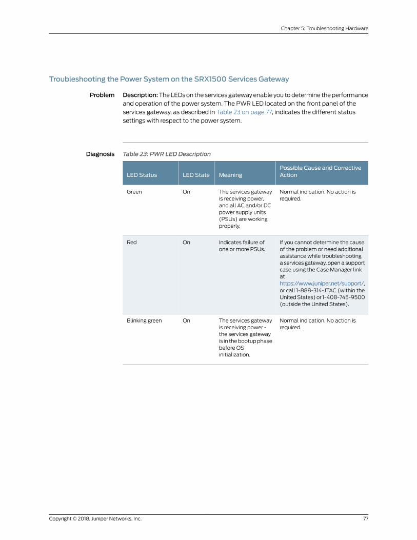
Troubleshooting the Power System on the SRX1500 Services Gateway
Problem Description:TheLEDson theservicesgatewayenable you todetermine theperformanceand operation of the power system. The PWR LED located on the front panel of the
services gateway, as described in Table 23 on page 77, indicates the different status
settings with respect to the power system.
Diagnosis Table 23: PWR LED Description
Possible Cause and CorrectiveActionMeaningLED StateLED Status
Normal indication. No action isrequired.
The services gatewayis receiving power,and all AC and/or DCpower supply units(PSUs) are workingproperly.
OnGreen
If you cannot determine the causeof the problem or need additionalassistance while troubleshootinga services gateway, opena supportcase using the Case Manager linkathttps://www.juniper.net/support/,or call 1-888-314-JTAC (within theUnitedStates)or 1-408-745-9500(outside the United States).
Indicates failure ofone or more PSUs.
OnRed
Normal indication. No action isrequired.
The services gatewayis receiving power -the services gatewayis in thebootupphasebefore OSinitialization.
OnBlinking green
77Copyright © 2018, Juniper Networks, Inc.
Chapter 5: Troubleshooting Hardware

Table 23: PWR LED Description (continued)
Possible Cause and CorrectiveActionMeaningLED StateLED Status
If a red alarm condition occurs,issue the show chassis alarmscommand todetermine the sourceof the problem.
• Verify that the AC power cordand/or DC power supply cableis not damaged. If the insulationis cracked or broken,immediately replace the cord orcable.
• Verify that the source circuitbreaker has the proper currentrating. Each power supply mustbe connected to a separatesource circuit breaker.
• Ensure that the power socketyouareplugged into is inworkingcondition.
• Connect the power supply to adifferent power source with anewpowercordorpowercables.If the power supply status LEDsindicate that the power supplyis not functioning normally, thepower supply is the sourceof theproblem. Replace the powersupply with a spare.
NOTE: If the system temperatureexceeds the threshold, Junos OSshuts down all power supplies sothat no status is displayed.
Junos OS also can shut down oneof the power supplies for otherreasons. In this case, the remainingpower supply provides power tothe services gateway, and you canstill view thesystemstatus throughthe CLI.
Indicates that theservices gateway isnot receiving power.
OffOff
Using the RESET CONFIG Button on the SRX1500 Services Gateway
If a configuration fails or denies management access to the services gateway, you can
use the RESET CONFIG button to restore the services gateway to the factory-default
configuration. The button is recessed to prevent it from being pressed accidentally.
To press the RESET CONFIG button, insert a small probe (such as a straightened paper
clip) into the pinhole on the front panel.
Copyright © 2018, Juniper Networks, Inc.78
SRX1500 Services Gateway Hardware Guide

CAUTION: Pressing and holding the RESET CONFIG button for 5 seconds ormore deletes all configurations (backup configurations and rescueconfiguration)onthedevice,and loadsandcommits the factoryconfiguration.
For details about factory-default settings, see “Viewing SRX1500 Services Gateway
Factory-Default Settings” on page 57.
Fordetailsaboutperforming initial softwareconfiguration, see “Configuring theSRX1500
Services Gateway Using the CLI” on page 63.
Changing the RESET CONFIG Button Behavior on the SRX1500 Services Gateway
You can change the default operation of the RESET CONFIG button of the SRX1500
Services Gateway by limiting how the button resets the services gateway:
• To prevent the RESET CONFIG button from setting the services gateway to the
factory-default configuration and deleting all other configurations, enter the following
command. You can still press and quickly release the button to reset it to the rescue
configuration.
user@host# set chassis config-button no-clear
• To prevent the RESET CONFIG button from setting the services gateway to the rescue
configuration, enter the following command. You can still press and hold the button
for 15 secondsormore to reset theservicesgateway to the factory-default configuration.
user@host# set chassis config-button no-rescue
• To disable the button and prevent the services gateway from resetting to either
configuration, enter the following command:
user@host# set chassis config-button no-clear no-rescue
The no-rescue option prevents the RESET CONFIG button from loading the rescue
configuration. The no-clear option prevents the RESET CONFIG button from deleting all
configurations on the services gateway.
To return the function of the RESET CONFIG button to its default behavior, remove the
config-button statement from the services gateway configuration.
79Copyright © 2018, Juniper Networks, Inc.
Chapter 5: Troubleshooting Hardware

Copyright © 2018, Juniper Networks, Inc.80
SRX1500 Services Gateway Hardware Guide
CHAPTER 6
Contacting Customer Support andReturning the Chassis or Components
• Returning the SRX1500 Chassis or Components on page 81
Returning the SRX1500 Chassis or Components
• Contacting Customer Support on page 81
• Returning a SRX1500 Services Gateway Component to Juniper Networks on page 82
• Locating the SRX1500 Services Gateway Chassis Serial Number and Agency
Labels on page 82
• Listing the SRX1500 Services Gateway Component Details with the CLI on page 82
• Required Tools and Parts for Packing the SRX1500 Services Gateway on page 83
• Packing the SRX1500 Services Gateway for Shipment on page 84
• Packing SRX1500 Services Gateway Components for Shipment on page 85
Contacting Customer Support
Once you have located the serial numbers of the device or component, you can return
the device or component for repair or replacement. For this, you need to contact Juniper
Networks Technical Assistance Center (JTAC).
You can contact JTAC 24 hours a day, 7 days aweek, using any of the followingmethods:
• On theWeb: Using the Case Manager link at https://www.juniper.net/support/
• By telephone:
• From the US and Canada: 1-888-314-JTAC
• From all other locations: 1-408-745-9500
NOTE: If contacting JTAC by telephone, enter your 11-digit case numberfollowed by the pound (#) key if this is an existing case, or press the star(*) key to be routed to the next available support engineer.
81Copyright © 2018, Juniper Networks, Inc.
When requesting support from JTAC by telephone, be prepared to provide the following
information:
• Your existing case number, if you have one
• Details of the failure or problem
• Type of activity being performed on the services gateway when the problem occurred
• Configuration data displayed by one or more show commands
• Your name, organization name, telephone number, fax number, and shipping address
The support representative validates your request and issues an RMA number for return
of the component.
Returning a SRX1500 Services Gateway Component to Juniper Networks
To return an SRX1500 Services Gateway or component to Juniper Networks for repair or
replacement:
1. Determine the part number and serial number of the services gateway or component.
2. Obtain a Return Materials Authorization (RMA) number from JTAC.
NOTE: Do not return the services gateway or any component to JuniperNetworksunlessyouhave firstobtainedanRMAnumber. JuniperNetworksreserves the right to refuse shipments that do not have an RMA. Refusedshipments are returned to the customer via collect freight.
3. Pack the SRX1500 Services Gateway or component for shipping.
Formore informationabout returnand repair policies, see thecustomer supportwebpage
at https://www.juniper.net/support/guidelines.html.
For product problems or technical support issues, open a support case using the Case
Manager link at https://www.juniper.net/support/ or call 1-888-314-JTAC (within the
United States) or 1-408-745-9500 (outside the United States).
Locating the SRX1500 Services Gateway Chassis Serial Number and Agency Labels
The chassis serial number is located on the side of the chassis.
Listing the SRX1500 Services Gateway Component Details with the CLI
Before contacting Juniper Networks to request a Return Materials Authorization (RMA),
youmust find the serial number on the SRX1500 Services Gateway or component.
Copyright © 2018, Juniper Networks, Inc.82
SRX1500 Services Gateway Hardware Guide
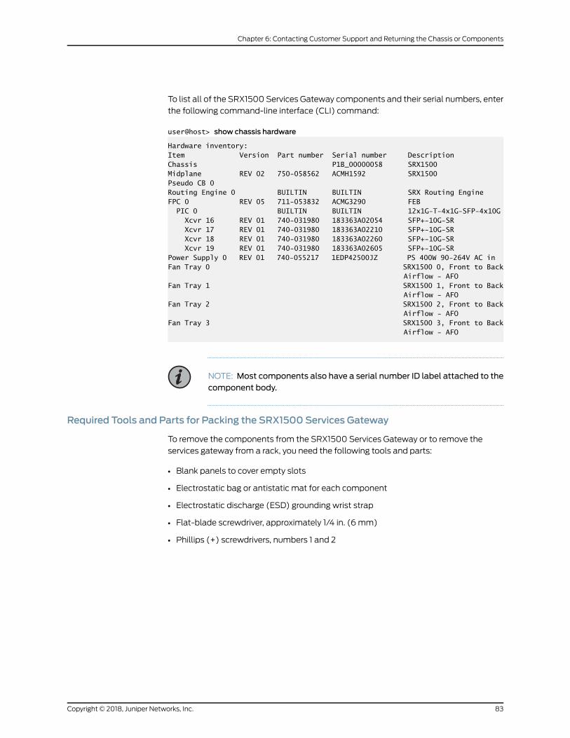
To list all of the SRX1500 Services Gateway components and their serial numbers, enter
the following command-line interface (CLI) command:
user@host> show chassis hardware
Hardware inventory:Item Version Part number Serial number DescriptionChassis P1B_00000058 SRX1500Midplane REV 02 750-058562 ACMH1592 SRX1500Pseudo CB 0 Routing Engine 0 BUILTIN BUILTIN SRX Routing EngineFPC 0 REV 05 711-053832 ACMG3290 FEB PIC 0 BUILTIN BUILTIN 12x1G-T-4x1G-SFP-4x10G Xcvr 16 REV 01 740-031980 183363A02054 SFP+-10G-SR Xcvr 17 REV 01 740-031980 183363A02210 SFP+-10G-SR Xcvr 18 REV 01 740-031980 183363A02260 SFP+-10G-SR Xcvr 19 REV 01 740-031980 183363A02605 SFP+-10G-SRPower Supply 0 REV 01 740-055217 1EDP42500JZ PS 400W 90-264V AC in Fan Tray 0 SRX1500 0, Front to Back Airflow - AFOFan Tray 1 SRX1500 1, Front to Back Airflow - AFOFan Tray 2 SRX1500 2, Front to Back Airflow - AFOFan Tray 3 SRX1500 3, Front to Back Airflow - AFO
NOTE: Most components also have a serial number ID label attached to thecomponent body.
Required Tools and Parts for Packing the SRX1500 Services Gateway
To remove the components from the SRX1500 Services Gateway or to remove the
services gateway from a rack, you need the following tools and parts:
• Blank panels to cover empty slots
• Electrostatic bag or antistatic mat for each component
• Electrostatic discharge (ESD) grounding wrist strap
• Flat-blade screwdriver, approximately 1/4 in. (6 mm)
• Phillips (+) screwdrivers, numbers 1 and 2
83Copyright © 2018, Juniper Networks, Inc.
Chapter 6: Contacting Customer Support and Returning the Chassis or Components

Packing the SRX1500 Services Gateway for Shipment
To pack the SRX1500 Services Gateway for shipment:
1. Retrieve the shipping carton and packingmaterials inwhich the services gatewaywas
originally shipped. If you do not have these materials, contact your Juniper Networks
representative about approved packaging materials.
2. Attachanelectrostaticdischarge (ESD)groundingstrap toyourbarewrist andconnect
the strap to the ESD point on the chassis or to an outside ESD point if the device is
disconnected from earth ground. For more information about ESD, see “Prevention
of Electrostatic Discharge Damage” on page 92.
3. On theconsoleor othermanagementdevice connected to the services gateway, enter
CLI operational mode and issue the following command to shut down the services
gateway software:
user@host> request system halt
Wait until a message appears on the console confirming that the operating system
has halted.
4. Shut down power to the services gateway by pressing the Power button on the front
of the services gateway.
5. Disconnect power from the services gateway.
6. Remove the cables that connect to all external devices.
7. If the services gateway is installed in a rack, have one person support the weight of
the services gateway while another person unscrews and removes the mounting
screws.
8. Place the services gateway in the shipping carton.
9. Cover the services gateway with an ESD bag, and place the packing foam on top of
and around the device.
10. Replace the accessory box on top of the packing foam.
11. Securely tape the box closed.
12. Write the Return Materials Authorization (RMA) number on the exterior of the box to
ensure proper tracking.
Copyright © 2018, Juniper Networks, Inc.84
SRX1500 Services Gateway Hardware Guide
Packing SRX1500 Services Gateway Components for Shipment
Follow these guidelines for packing and shipping individual components of the services
gateway:
• When you return a component, make sure that it is adequately protectedwith packing
materials and packed so that the pieces are prevented frommoving around inside the
carton.
• Use the original shipping materials if they are available.
• Place the individual component in an electrostatic bag.
• Write the Return Materials Authorization (RMA) number on the exterior of the box to
ensure proper tracking.
CAUTION: Do not stack any of the services gateway components duringpacking.
85Copyright © 2018, Juniper Networks, Inc.
Chapter 6: Contacting Customer Support and Returning the Chassis or Components

Copyright © 2018, Juniper Networks, Inc.86
SRX1500 Services Gateway Hardware Guide

CHAPTER 7
Safety and Compliance Information
• Definitions of SafetyWarning Levels on page 87
• General Safety Guidelines andWarnings on page 89
• Restricted AccessWarning on page 90
• Qualified Personnel Warning on page 91
• Prevention of Electrostatic Discharge Damage on page 92
• Fire Safety Requirements on page 94
• Laser and LED Safety Guidelines andWarnings on page 95
• Radiation fromOpen Port AperturesWarning on page 97
• Maintenance and Operational Safety Guidelines andWarnings on page 98
• Action to Take After an Electrical Accident on page 103
• General Electrical Safety Guidelines andWarnings on page 103
• AC Power Electrical Safety Guidelines on page 107
• DC Power Electrical Safety Guidelines on page 108
• SRX1500 Services Gateway Agency Approvals on page 114
• SRX1500 Services Gateway Acoustic Noise Compliance Statements on page 115
• SRX1500 Services Gateway EMC Requirements on page 116
Definitions of SafetyWarning Levels
The documentation uses the following levels of safety warnings (there are twoWarning
formats):
NOTE: Youmight find this information helpful in a particular situation, or youmight overlook this important information if it was not highlighted in a Note.
CAUTION: You need to observe the specified guidelines to prevent minorinjury or discomfort to you or severe damage to the device.
87Copyright © 2018, Juniper Networks, Inc.
WARNING: This symbol alerts you to the risk of personal injury from a laser.
WARNING: This symbolmeansdanger.Youare inasituation thatcouldcausebodily injury. Before you work on any equipment, be aware of the hazardsinvolved with electrical circuitry and be familiar with standard practices forpreventing accidents.
Waarschuwing Dit waarschuwingssymbool betekent gevaar. U verkeert ineen situatie die lichamelijk letsel kan veroorzaken. Voordat u aan enigeapparatuur gaat werken, dient u zich bewust te zijn van de bij elektrischeschakelingen betrokken risico's en dient u opde hoogte te zijn van standaardmaatregelen om ongelukken te voorkomen.
Varoitus Tämä varoitusmerkki merkitsee vaaraa. Olet tilanteessa, joka voijohtaa ruumiinvammaan.Ennenkuin työskenteletminkään laitteistonparissa,ota selvää sähkökytkentöihin liittyvistä vaaroista ja tavanomaisistaonnettomuuksien ehkäisykeinoista.
AttentionCe symbole d'avertissement indique un danger. Vous vous trouvezdansunesituationpouvantcauserdesblessuresoudesdommagescorporels.Avant de travailler sur un équipement, soyez conscient des dangers poséspar les circuits électriques et familiarisez-vous avec les procédurescouramment utilisées pour éviter les accidents.
Warnung DiesesWarnsymbol bedeutet Gefahr. Sie befinden sich in einerSituation, die zu einer Körperverletzung führen könnte. Bevor Sie mit derArbeit an irgendeinemGerät beginnen, seien Sie sich der mit elektrischenStromkreisen verbundenen Gefahren und der Standardpraktiken zurVermeidung von Unfällen bewußt.
AvvertenzaQuesto simbolo di avvertenza indica un pericolo. La situazionepotrebbe causare infortuni alle persone. Prima di lavorare su qualsiasiapparecchiatura, occorre conoscere i pericoli relativi ai circuiti elettrici edessere al corrente delle pratiche standard per la prevenzione di incidenti.
AdvarselDette varselsymbolet betyr fare. Du befinner deg i en situasjon somkan føre til personskade. Før du utfører arbeid på utstyr, må du vareoppmerksom på de faremomentene som elektriske kretser innebærer, samtgjøre deg kjent med vanlig praksis når det gjelder å unngå ulykker.
Aviso Este símbolo de aviso indica perigo. Encontra-se numa situação quelhepoderá causar danos físicos. Antes de começar a trabalhar comqualquerequipamento, familiarize-se com os perigos relacionados com circuitoseléctricos, e com quaisquer práticas comuns que possam prevenir possíveisacidentes.
¡Atención! Este símbolo de aviso significa peligro. Existe riesgo para suintegridad física. Antes demanipular cualquier equipo, considerar los riesgos
Copyright © 2018, Juniper Networks, Inc.88
SRX1500 Services Gateway Hardware Guide

que entraña la corriente eléctrica y familiarizarse con los procedimientosestándar de prevención de accidentes.
Varning!Denna varningssymbol signalerar fara. Du befinner dig i en situationsom kan leda till personskada. Innan du utför arbete på någon utrustningmåste du varamedveten om farornamed elkretsar och känna till vanligtförfarande för att förebygga skador.
RelatedDocumentation
Laser and LED Safety Guidelines andWarnings for the ACX5000 Router•
• Laser and LED Safety Guidelines andWarnings for the QFX Series
• Laser and LED Safety Guidelines andWarnings for the PTX10008 and PTX10016
General Safety Guidelines andWarnings
The following guidelines help ensure your safety and protect the device from damage.
The list of guidelinesmightnotaddressall potentially hazardoussituations in yourworking
environment, so be alert and exercise good judgment at all times.
• Perform only the procedures explicitly described in the hardware documentation for
this device. Make sure that only authorized service personnel perform other system
services.
• Keep the area around the device clear and free from dust before, during, and after
installation.
• Keep tools away from areas where people could trip over themwhile walking.
• Do not wear loose clothing or jewelry, such as rings, bracelets, or chains, which could
become caught in the device.
• Wear safety glasses if you are working under any conditions that could be hazardous
to your eyes.
• Do not perform any actions that create a potential hazard to people or make the
equipment unsafe.
• Never attempt to lift an object that is too heavy for one person to handle.
• Never install or manipulate wiring during electrical storms.
• Never install electrical jacks in wet locations unless the jacks are specifically designed
for wet environments.
• Operate the device only when it is properly grounded.
• Ensure that the separate protective earthing terminal provided on this device is
permanently connected to earth.
• Replace fuses only with fuses of the same type and rating.
89Copyright © 2018, Juniper Networks, Inc.
Chapter 7: Safety and Compliance Information
• Do not open or remove chassis covers or sheet-metal parts unless instructions are
provided in the hardware documentation for this device. Such an action could cause
severe electrical shock.
• Do not push or force any objects through any opening in the chassis frame. Such an
action could result in electrical shock or fire.
• Avoid spilling liquid onto the chassis or onto any device component. Such an action
could cause electrical shock or damage the device.
• Avoid touching uninsulated electrical wires or terminals that have not been
disconnected from their power source. Such an action could cause electrical shock.
• Some parts of the chassis, including AC and DC power supply surfaces, power supply
unit handles, SFB card handles, and fan tray handlesmight become hot. The following
label provides the warning of the hot surfaces on the chassis:
• Always ensure that all modules, power supplies, and cover panels are fully inserted
and that the installation screws are fully tightened.
Restricted AccessWarning
WARNING: This unit is intended for installation in restricted access areas. Arestrictedaccessarea isanarea towhichaccesscanbegainedonlybyservicepersonnel through the use of a special tool, lock and key, or other means ofsecurity, andwhich is controlled by the authority responsible for the location.
WaarschuwingDit toestel isbedoeldvoor installatieopplaatsenmetbeperktetoegang.Eenplaatsmetbeperkte toegang iseenplaatswaar toegangslechtsdoor servicepersoneel verkregen kan worden door middel van een speciaalinstrument, een slot en sleutel, of een ander veiligheidsmiddel, en welkebeheerd wordt door de overheidsinstantie die verantwoordelijk is voor delocatie.
Varoitus Tämä laite on tarkoitettu asennettavaksi paikkaan, johon pääsy onrajoitettua. Paikka, johon pääsy on rajoitettua, tarkoittaa paikkaa, johon vainhuoltohenkilöstö pääsee jonkin erikoistyökalun, lukkoon sopivan avaimentai jonkin muun turvalaitteen avulla ja joka on paikasta vastuussa olevientoimivaltaisten henkilöiden valvoma.
Attention Cet appareil est à installer dans des zones d'accès réservé. Cesdernières sontdeszonesauxquelles seul lepersonneldeservicepeutaccéderen utilisant un outil spécial, unmécanisme de verrouillage et une clé, ou toutautre moyen de sécurité. L'accès aux zones de sécurité est sous le contrôlede l'autorité responsable de l'emplacement.
Copyright © 2018, Juniper Networks, Inc.90
SRX1500 Services Gateway Hardware Guide

Warnung Diese Einheit ist zur Installation in Bereichenmit beschränktemZutritt vorgesehen. Ein Bereichmit beschränktem Zutritt ist ein Bereich, zudem nurWartungspersonal mit einem Spezialwerkzeugs, Schloß undSchlüssel oder anderer Sicherheitsvorkehrungen Zugang hat, und der vondem für die Anlage zuständigen Gremium kontrolliert wird.
AvvertenzaQuestaunitàdeveessere installata inun'areaadaccesso limitato.Un'area ad accesso limitato è un'area accessibile solo a personale diassistenza tramite un'attrezzo speciale, lucchetto, o altri dispositivi disicurezza, ed è controllata dall'autorità responsabile della zona.
Advarsel Denne enheten er laget for installasjon i områder med begrensetadgang.Etområdemedbegrensetadganggir kunadgangtil servicepersonalesom bruker et spesielt verktøy, lås og nøkkel, eller en annensikkerhetsanordning, og det kontrolleres av den autoriteten som er ansvarligfor området.
AvisoEstaunidade foi concebidapara instalaçãoemáreasdeacesso restrito.Uma área de acesso restrito é uma área à qual apenas temacesso o pessoalde serviço autorizado, que possua uma ferramenta, chave e fechaduraespecial, ou qualquer outra forma de segurança. Esta área é controlada pelaautoridade responsável pelo local.
¡Atención! Esta unidad ha sido diseñada para instalarse en áreas de accesorestringido. Área de acceso restringido significa un área a la que solamentetieneaccesoelpersonaldeserviciomediante lautilizacióndeunaherramientaespecial, cerradura con llave, o algún otromedio de seguridad, y que estábajo el control de la autoridad responsable del local.
Varning! Denna enhet är avsedd för installation i områdenmed begränsattillträde. Ett områdemed begränsat tillträde får endast tillträdas avservicepersonal med ett speciellt verktyg, lås och nyckel, eller annansäkerhetsanordning, och kontrolleras av den auktoritet som ansvarar förområdet.
Qualified PersonnelWarning
WARNING: Only trainedandqualified personnel should install or replace thedevice.
Waarschuwing Installatie en reparaties mogen uitsluitend door getraind enbevoegd personeel uitgevoerd worden.
VaroitusAinoastaankoulutettu japätevähenkilökuntasaaasentaatai vaihtaatämän laitteen.
Attention Tout installation ou remplacement de l'appareil doit être réalisépar du personnel qualifié et compétent.
91Copyright © 2018, Juniper Networks, Inc.
Chapter 7: Safety and Compliance Information
WarnungGerät nur vongeschultem, qualifiziertemPersonal installierenoderauswechseln lassen.
Avvertenza Solo personale addestrato e qualificato deve essere autorizzatoad installare o sostituire questo apparecchio.
Advarsel Kun kvalifisert personell med riktig opplæring bør montere ellerbytte ut dette utstyret.
Aviso Este equipamento deverá ser instalado ou substituído apenas porpessoal devidamente treinado e qualificado.
¡Atención! Estos equipos deben ser instalados y reemplazadosexclusivamenteporpersonal técnicoadecuadamentepreparadoycapacitado.
Varning! Denna utrustning ska endast installeras och bytas ut av utbildadoch kvalificerad personal.
RelatedDocumentation
PTX5000 AC Power Electrical Safety Guidelines•
• PTX5000 AC Power Electrical Safety Warnings
• PTX1000 DC Power Electrical Safety Guidelines
• PTX3000 DC Power Electrical Safety Guidelines
• PTX5000 DC Power Electrical Safety Guidelines
Prevention of Electrostatic Discharge Damage
Device components that are shipped in antistatic bags are sensitive to damage from
static electricity. Some components can be impaired by voltages as low as 30 V. You
can easily generate potentially damaging static voltages whenever you handle plastic
or foam packing material or if youmove components across plastic or carpets. Observe
the following guidelines to minimize the potential for electrostatic discharge (ESD)
damage, which can cause intermittent or complete component failures:
Copyright © 2018, Juniper Networks, Inc.92
SRX1500 Services Gateway Hardware Guide

• Always use an ESDwrist strap when you are handling components that are subject to
ESD damage, andmake sure that it is in direct contact with your skin.
If a grounding strap is not available, hold the component in its antistatic bag (see
Figure 19 on page 93) in one hand and touch the exposed, bare metal of the device
with the other hand immediately before inserting the component into the device.
WARNING: For safety, periodically check the resistance value of the ESDgrounding strap. Themeasurementmust be in the range 1 through10Mohms.
• When handling any component that is subject to ESD damage and that is removed
from the device, make sure the equipment end of your ESDwrist strap is attached to
the ESD point on the chassis.
If nogrounding strap is available, touch theexposed, baremetal of thedevice toground
yourself before handling the component.
• Avoidcontactbetween thecomponent that is subject toESDdamageandyourclothing.
ESD voltages emitted from clothing can damage components.
• When removing or installing a component that is subject to ESDdamage, always place
it component-side up on an antistatic surface, in an antistatic card rack, or in an
antistatic bag (see Figure 19 on page 93). If you are returning a component, place it in
an antistatic bag before packing it.
Figure 19: Placing a Component into an Antistatic Bag
6xGE
SFP
0
1
2
3
4
5
CAUTIONELECTROSTATIC
SENSITIVEDEVICES
DO NOT OPEN OR HANDLEEXCEPT AT A
STATIC-FREE WORKSTATION
CAUTION: ANSI/TIA/EIA-568 cables such as Category 5e and Category 6can get electrostatically charged. To dissipate this charge, always groundthe cables to a suitable and safe earth groundbefore connecting them to thesystem.
93Copyright © 2018, Juniper Networks, Inc.
Chapter 7: Safety and Compliance Information

Fire Safety Requirements
In the event of a fire emergency, the safety of people is the primary concern. You should
establishprocedures for protectingpeople in theeventof a fire emergency, provide safety
training, and properly provision fire-control equipment and fire extinguishers.
In addition, you should establish procedures to protect your equipment in the event of a
fire emergency. JuniperNetworksproducts shouldbe installed inanenvironment suitable
for electronic equipment. We recommend that fire suppression equipment be available
in the event of a fire in the vicinity of the equipment and that all local fire, safety, and
electrical codesandordinancesbeobservedwhenyou install andoperateyourequipment.
Fire Suppression
In the event of an electrical hazard or an electrical fire, you should first turn power off to
theequipmentat the source. ThenuseaTypeC fire extinguisher,whichusesnoncorrosive
fire retardants, to extinguish the fire.
Fire Suppression Equipment
Type C fire extinguishers, which use noncorrosive fire retardants such as carbon dioxide
andHalotron™,aremosteffective for suppressingelectrical fires. TypeC fire extinguishers
displace oxygen from the point of combustion to eliminate the fire. For extinguishing fire
on or around equipment that draws air from the environment for cooling, you should use
this type of inert oxygen displacement extinguisher instead of an extinguisher that leaves
residues on equipment.
Do not use multipurpose Type ABC chemical fire extinguishers (dry chemical fire
extinguishers). The primary ingredient in these fire extinguishers is monoammonium
phosphate,which is very sticky anddifficult to clean. In addition, in thepresenceofminute
amounts of moisture, monoammonium phosphate can become highly corrosive and
corrodes most metals.
Any equipment in a room in which a chemical fire extinguisher has been discharged is
subject to premature failure and unreliable operation. The equipment is considered to
be irreparably damaged.
NOTE: Tokeepwarrantieseffective,donotuseadrychemical fireextinguisherto control a fire at or near a Juniper Networks device. If a dry chemical fireextinguisher is used, the unit is no longer eligible for coverage under a serviceagreement.
We recommend that you dispose of any irreparably damaged equipment in an
environmentally responsible manner.
Copyright © 2018, Juniper Networks, Inc.94
SRX1500 Services Gateway Hardware Guide
Laser and LED Safety Guidelines andWarnings
Juniper Networks devices are equipped with laser transmitters, which are considered a
Class 1 Laser Product by the U.S. Food and Drug Administration and are evaluated as a
Class 1 Laser Product per EN 60825-1 requirements.
Observe the following guidelines and warnings:
• General Laser Safety Guidelines on page 95
• Class 1 Laser ProductWarning on page 95
• Class 1 LED ProductWarning on page 96
• Laser BeamWarning on page 96
General Laser Safety Guidelines
When working around ports that support optical transceivers, observe the following
safety guidelines to prevent eye injury:
• Do not look into unterminated ports or at fibers that connect to unknown sources.
• Do not examine unterminated optical ports with optical instruments.
• Avoid direct exposure to the beam.
WARNING: Unterminated optical connectors can emit invisible laserradiation. The lens in the human eye focuses all the laser power on theretina, so focusing the eye directly on a laser source—even a low-powerlaser—could permanently damage the eye.
Class 1 Laser ProductWarning
WARNING: Class 1 laser product.
Waarschuwing Klasse-1 laser produkt.
Varoitus Luokan 1 lasertuote.
Attention Produit laser de classe I.
Warnung Laserprodukt der Klasse 1.
Avvertenza Prodotto laser di Classe 1.
Advarsel Laserprodukt av klasse 1.
Aviso Produto laser de classe 1.
¡Atención! Producto láser Clase I.
95Copyright © 2018, Juniper Networks, Inc.
Chapter 7: Safety and Compliance Information

Varning! Laserprodukt av klass 1.
Class 1 LED ProductWarning
WARNING: Class 1 LED product.
Waarschuwing Klasse 1 LED-product.
Varoitus Luokan 1 valodiodituote.
Attention Alarme de produit LED Class I.
Warnung Class 1 LED-Produktwarnung.
Avvertenza Avvertenza prodotto LED di Classe 1.
Advarsel LED-produkt i klasse 1.
Aviso Produto de classe 1 com LED.
¡Atención! Aviso sobre producto LED de Clase 1.
Varning! Lysdiodprodukt av klass 1.
Laser BeamWarning
WARNING: Do not stare into the laser beam or view it directly with opticalinstruments.
WaarschuwingNiet in de straal staren of hem rechtstreeks bekijkenmetoptische instrumenten.
Varoitus Älä katso säteeseen äläkä tarkastele sitä suoraan optisen laitteenavulla.
AttentionNe pas fixer le faisceau des yeux, ni l'observer directement à l'aided'instruments optiques.
WarnungNicht direkt in den Strahl blicken und ihn nicht direktmit optischenGeräten prüfen.
AvvertenzaNon fissare il raggio con gli occhi né usare strumenti ottici perosservarlo direttamente.
Advarsel Stirr eller se ikke direkte p strlenmed optiske instrumenter.
AvisoNão olhe fixamente para o raio, nem olhe para ele directamente cominstrumentos ópticos.
Copyright © 2018, Juniper Networks, Inc.96
SRX1500 Services Gateway Hardware Guide
¡Atención!Nomirar fijamente el haz ni observarlo directamente coninstrumentos ópticos.
Varning! Rikta inte blicken in mot strålen och titta inte direkt på den genomoptiska instrument.
Radiation fromOpen Port AperturesWarning
WARNING: Because invisible radiationmight be emitted from the apertureof the portwhen no fiber cable is connected, avoid exposure to radiation anddo not stare into open apertures.
Waarschuwing Aangezien onzichtbare straling vanuit de opening van depoort kan komen als er geen fiberkabel aangesloten is, dient blootstellingaan straling en het kijken in open openingen vermeden te worden.
Varoitus Koska portin aukosta voi emittoitua näkymätöntä säteilyä, kunkuitukaapelia ei ole kytkettynä, vältä säteilylle altistumista äläkä katsoavoimiin aukkoihin.
Attention Des radiations invisibles à l'il nu pouvant traverser l'ouverture duport lorsqu'aucun câble en fibre optique n'y est connecté, il est recommandéde ne pas regarder fixement l'intérieur de ces ouvertures.
Warnung Aus der Port-Öffnung können unsichtbare Strahlen emittieren,wenn kein Glasfaserkabel angeschlossen ist. Vermeiden Sie es, sich denStrahlungen auszusetzen, und starren Sie nicht in die Öffnungen!
AvvertenzaQuando i cavi in fibranonsono inseriti, radiazioni invisibili possonoessere emesse attraverso l'apertura della porta. Evitate di esporvi alleradiazioni e non guardate direttamente nelle aperture.
AdvarselUnngåutsettelse for stråling, ogstirr ikke inn i åpninger someråpne,fordi usynlig stråling kan emiteres fra portens åpning når det ikke er tilkobleten fiberkabel.
AvisoDadaapossibilidadedeemissãode radiação invisível atravésdoorifícioda via de acesso, quando esta não tiver nenhum cabo de fibra conectado,deverá evitar a exposição à radiação e não deverá olhar fixamente paraorifícios que se encontrarem a descoberto.
¡Atención!Debidoaque laaperturadelpuertopuedeemitir radiación invisiblecuando no existe un cable de fibra conectado, evitemirar directamente a lasaperturas para no exponerse a la radiación.
Varning!Osynlig strålning kan avges från en portöppning utan anslutenfiberkabel ochdubör därför undvika att bli utsatt för strålning genomatt intestirra in i oskyddade öppningar.
97Copyright © 2018, Juniper Networks, Inc.
Chapter 7: Safety and Compliance Information
Maintenance and Operational Safety Guidelines andWarnings
Whileperforming themaintenanceactivities fordevices, observe the followingguidelines
and warnings:
• Battery HandlingWarning on page 98
• Jewelry Removal Warning on page 99
• Lightning Activity Warning on page 100
• Operating TemperatureWarning on page 101
• Product Disposal Warning on page 102
Battery HandlingWarning
WARNING: Replacing a battery incorrectly might result in an explosion.Replace a battery only with the same or equivalent type recommended bythemanufacturer. Disposeof usedbatteries according to themanufacturer'sinstructions.
Waarschuwing Er is ontploffingsgevaar als de batterij verkeerd vervangenwordt. Vervang de batterij slechts met hetzelfde of een equivalent type datdoor de fabrikant aanbevolen is. Gebruikte batterijendienenovereenkomstigfabrieksvoorschriften weggeworpen te worden.
Varoitus Räjähdyksen vaara, jos akku on vaihdettu väärään akkuun. Käytävaihtamiseen ainoastaan saman- tai vastaavantyyppistä akkua, joka onvalmistajansuosittelema.Hävitäkäytetytakutvalmistajanohjeidenmukaan.
Attention Danger d'explosion si la pile n'est pas remplacée correctement.Ne la remplacer que par une pile de type semblable ou équivalent,recommandée par le fabricant. Jeter les piles usagées conformément auxinstructions du fabricant.
Warnung Bei Einsetzen einer falschen Batterie besteht Explosionsgefahr.Ersetzen Sie die Batterie nur durch den gleichen oder vomHerstellerempfohlenen Batterietyp. Entsorgen Sie die benutzten Batterien nach denAnweisungen des Herstellers.
Advarsel Det kan være fare for eksplosjon hvis batteriet skiftes på feil måte.Skift kunmed sammeeller tilsvarende type somer anbefalt av produsenten.Kasser brukte batterier i henhold til produsentens instruksjoner.
Avvertenza Pericolo di esplosione se la batteria non è installatacorrettamente.Sostituiresoloconunadi tipougualeoequivalente, consigliatadalproduttore. Eliminare lebatterieusatesecondo le istruzionidelproduttore.
AvisoExiste perigo de explosão se a bateria for substituída incorrectamente.Substitua a bateria por uma bateria igual ou de um tipo equivalente
Copyright © 2018, Juniper Networks, Inc.98
SRX1500 Services Gateway Hardware Guide

recomendado pelo fabricante. Destrua as baterias usadas conforme asinstruções do fabricante.
¡Atención! Existe peligro de explosión si la batería se reemplaza demaneraincorrecta. Reemplazar la batería exclusivamente con el mismo tipo o elequivalente recomendado por el fabricante. Desechar las baterías gastadassegún las instrucciones del fabricante.
Varning!Explosionsfara vid felaktigt batteribyte. Ersätt endast batterietmedsamma batterityp som rekommenderas av tillverkaren eller motsvarande.Följ tillverkarens anvisningar vid kassering av använda batterier.
Jewelry RemovalWarning
WARNING: Before working on equipment that is connected to power lines,remove jewelry, including rings, necklaces, and watches. Metal objects heatupwhen connected to power and ground and can cause serious burns or canbe welded to the terminals.
Waarschuwing Alvorens aan apparatuur te werken die met elektrischeleidingen is verbonden, sieraden (inclusief ringen, kettingen en horloges)verwijderen. Metalen voorwerpen worden warmwanneer zemet stroom enaarde zijn verbonden, en kunnen ernstige brandwonden veroorzaken of hetmetalen voorwerp aan de aansluitklemmen lassen.
Varoitus Ennen kuin työskentelet voimavirtajohtoihin kytkettyjen laitteidenparissa, otapois kaikki korut (sormukset, kaulakorut ja kellotmukaan lukien).Metalliesineet kuumenevat, kun ne ovat yhteydessä sähkövirran ja maankanssa, janevoivataiheuttaavakaviapalovammoja tai hitsatametalliesineetkiinni liitäntänapoihin.
AttentionAvantd'accéderàcetéquipementconnectéaux lignesélectriques,ôter toutbijou(anneaux,colliersetmontrescompris). Lorsqu'ilssontbranchésà l'alimentation et reliés à la terre, les objets métalliques chauffent, ce quipeutprovoquerdesblessuresgravesousouder l'objetmétalliqueauxbornes.
Warnung Vor der Arbeit an Geräten, die an das Netz angeschlossen sind,jeglichen Schmuck (einschließlich Ringe, Ketten und Uhren) abnehmen.Metallgegenstände erhitzen sich, wenn sie an das Netz und die Erdeangeschlossen werden, und können schwere Verbrennungen verursachenoder an die Anschlußklemmen angeschweißt werden.
Avvertenza Prima di intervenire su apparecchiature collegate alle linee dialimentazione, togliersi qualsiasi monile (inclusi anelli, collane, braccialettied orologi). Gli oggetti metallici si riscaldano quando sono collegati tra puntidi alimentazione emassa: possono causare ustioni gravi oppure il metallopuò saldarsi ai terminali.
99Copyright © 2018, Juniper Networks, Inc.
Chapter 7: Safety and Compliance Information
Advarsel Fjern alle smykker (inkludert ringer, halskjeder og klokker) før duskal arbeidepåutstyr somer koblet til kraftledninger.Metallgjenstander somer koblet til kraftledninger og jord blir svært varme og kan forårsake alvorligebrannskader eller smelte fast til polene.
Aviso Antes de trabalhar em equipamento que esteja ligado a linhas decorrente, retire todas as jóias que estiver a usar (incluindo anéis, fios erelógios). Os objectosmetálicos aquecerão em contacto com a corrente eem contacto com a ligação à terra, podendo causar queimaduras graves ouficarem soldados aos terminais.
¡Atención! Antes de operar sobre equipos conectados a líneas dealimentación, quitarse las joyas (incluidos anillos, collares y relojes). Losobjetosdemetal secalientancuandoseconectana laalimentaciónyatierra,lo que puede ocasionar quemaduras graves o que los objetosmetálicosqueden soldados a los bornes.
Varning! Tag av alla smycken (inklusive ringar, halsband och armbandsur)innanduarbetarpåutrustningsomärkopplad till kraftledningar.Metallobjekthettas upp när de kopplas ihopmed ström och jord och kan förorsakaallvarliga brännskador; metallobjekt kan också sammansvetsasmedkontakterna.
Lightning ActivityWarning
WARNING: Donotworkon thesystemorconnectordisconnectcablesduringperiods of lightning activity.
Waarschuwing Tijdens onweer dat gepaard gaat met bliksem, dient u nietaan het systeem te werken of kabels aan te sluiten of te ontkoppelen.
Varoitus Älä työskentele järjestelmän parissa äläkä yhdistä tai irrotakaapeleita ukkosilmalla.
AttentionNe pas travailler sur le système ni brancher ou débrancher lescâbles pendant un orage.
Warnung Arbeiten Sie nicht am System und schließen Sie keine Kabel anbzw. trennen Sie keine ab, wenn es gewittert.
AvvertenzaNon lavorare sul sistema o collegare oppure scollegare i cavidurante un temporale con fulmini.
AdvarselUtfør aldri arbeidpåsystemet, eller koble kabler til eller fra systemetnår det tordner eller lyner.
AvisoNão trabalhe no sistema ou ligue e desligue cabos durante períodosdemau tempo (trovoada).
Copyright © 2018, Juniper Networks, Inc.100
SRX1500 Services Gateway Hardware Guide
¡Atención!No operar el sistema ni conectar o desconectar cables durante eltranscurso de descargas eléctricas en la atmósfera.
Varning!Vid åska skall du aldrig utföra arbete på systemet eller ansluta ellerkoppla loss kablar.
Operating TemperatureWarning
WARNING: To prevent the device from overheating, do not operate it in anarea that exceeds themaximum recommended ambient temperature. Toprevent airflow restriction, allow at least 6 in. (15.2 cm) of clearance aroundthe ventilation openings.
WaarschuwingOm te voorkomen dat welke switch van de Juniper Networksrouter dan ook oververhit raakt, dient u deze niet te bedienen op een plaatswaar demaximale aanbevolen omgevingstemperatuur van 40° Cwordtoverschreden. Om te voorkomen dat de luchtstroomwordt beperkt, dient erminstens 15,2 cm speling rond de ventilatie-openingen te zijn.
Varoitus Ettei Juniper Networks switch-sarjan reititin ylikuumentuisi, sitä eisaa käyttää tilassa, jonka lämpötila ylittää korkeimman suositellunympäristölämpötilan 40° C. Ettei ilmanvaihto estyisi, tuuletusaukkojenympärille on jätettävä ainakin 15,2 cm tilaa.
Attention Pour éviter toute surchauffe des routeurs de la gamme JuniperNetworks switch, ne l'utilisez pas dans une zoneoù la température ambianteest supérieure à 40° C. Pour permettre un flot d'air constant, dégagez unespace d'aumoins 15,2 cm autour des ouvertures de ventilations.
WarnungUmeinenRouterder switchvorÜberhitzungzuschützen,darfdiesernicht in einer Gegend betrieben werden, in der die Umgebungstemperaturdas empfohlene Maximum von 40° C überschreitet. Um Lüftungsverschlußzu verhindern, achten Sie darauf, daßmindestens 15,2 cm lichter Raum umdie Lüftungsöffnungen herum frei bleibt.
Avvertenza Per evitare il surriscaldamento dei switch, non adoperateli in unlocale che ecceda la temperatura ambientale massima di 40° C. Per evitareche lacircolazionedell'aria sia impedita, lasciateunospaziodialmeno 15.2cmdi fronte alle aperture delle ventole.
AdvarselUnngåoveropphetingaveventuelle rutere i JuniperNetworksswitchDisse skal ikke brukes på steder der den anbefalte maksimaleomgivelsestemperaturen overstiger 40° C (104° F). Sørg for at klaringenrundt lufteåpningene er minst 15,2 cm (6 tommer) for å forhindre nedsattluftsirkulasjon.
Aviso Para evitar o sobreaquecimento do encaminhador Juniper Networksswitch, não utilize este equipamento numa área que exceda a temperatura
101Copyright © 2018, Juniper Networks, Inc.
Chapter 7: Safety and Compliance Information
máxima recomendada de 40° C. Para evitar a restrição à circulação de ar,deixe pelomenos um espaço de 15,2 cm à volta das aberturas de ventilação.
¡Atención! Para impedir que un encaminador de la serie Juniper Networksswitch se recaliente, no lo haga funcionar en un área en la que se supere latemperatura ambientemáxima recomendada de 40° C. Para impedir larestricciónde laentradadeaire, dejeunespaciomínimode 15,2 cmalrededorde las aperturas para ventilación.
Varning! Förhindra att en Juniper Networks switch överhettas genomatt inteanvända den i ett område där denmaximalt rekommenderadeomgivningstemperaturenpå40°Cöverskrids. Förhindraatt luftcirkulationeninskränksgenomattse till attdet finns fritt utrymmepåminst 15,2cmomkringventilationsöppningarna.
Product DisposalWarning
WARNING: Disposal of this devicemust be handled according to all nationallaws and regulations.
Waarschuwing Dit produkt dient volgens alle landelijke wetten envoorschriften te worden afgedankt.
VaroitusTämän tuotteen lopullisesta hävittämisestä tulee huolehtia kaikkiavaltakunnallisia lakeja ja säännöksiä noudattaen.
Attention Lamise au rebut définitive de ce produit doit être effectuéeconformément à toutes les lois et réglementations en vigueur.
Warnung Dieses Produkt muß den geltenden Gesetzen und Vorschriftenentsprechend entsorgt werden.
Avvertenza L'eliminazione finale di questo prodotto deve essere eseguitaosservando le normative italiane vigenti in materia
AdvarselEndeligdisponeringavdetteproduktetmåskje ihenholdtil nasjonalelover og forskrifter.
Aviso A descartagem final deste produto deverá ser efectuada de acordocom os regulamentos e a legislação nacional.
¡Atención! El desecho final de este producto debe realizarse según todas lasleyes y regulaciones nacionales
Varning!Slutlig kasseringavdennaproduktbör skötas i enlighetmed landetsalla lagar och föreskrifter.
Copyright © 2018, Juniper Networks, Inc.102
SRX1500 Services Gateway Hardware Guide
Action to Take After an Electrical Accident
If an electrical accident results in an injury, take the following actions in this order:
1. Use caution. Be aware of potentially hazardous conditions that could cause further
injury.
2. Disconnect power from the device.
3. If possible, send another person to get medical aid. Otherwise, assess the condition
of the victim, then call for help.
General Electrical Safety Guidelines andWarnings
Safety Guidelines andWarnings
• Install the services gateway in compliance with the following local, national, or
international electrical codes:
• United States—National Fire Protection Association (NFPA 70), United States
National Electrical Code
• Canada—Canadian Electrical Code, Part 1, CSA C22.1
• Other countries—International Electromechanical Commission (IEC) 60364, Part 1
through Part 7
• Evaluated to the TN power system
• Locate the emergency power-off switch for the room in which you are working so that
if an electrical accident occurs, you can quickly turn off the power.
• Donotworkalone if potentially hazardousconditionsexist anywhere in yourworkspace.
• Never assume thatpower is disconnected fromacircuit. Always check thecircuit before
starting to work.
• Carefully look for possible hazards in your work area, such asmoist floors, ungrounded
power extension cords, andmissing safety grounds.
• Operate the services gateway within marked electrical ratings and product usage
instructions.
• For the services gateway and peripheral equipment to function safely and correctly,
use the cables and connectors specified for the attached peripheral equipment, and
make certain they are in good condition.
103Copyright © 2018, Juniper Networks, Inc.
Chapter 7: Safety and Compliance Information
Grounded EquipmentWarning
WARNING: The services gateway is intended to be grounded. Ensure thatthe services gateway is connected to earth ground during normal use.
Waarschuwing Deze apparatuur hoort geaard te worden Zorg dat dehost-computer tijdens normaal gebruik met aarde is verbonden.
Varoitus Tämä laitteisto on tarkoitettumaadoitettavaksi. Varmista, ettäisäntälaite on yhdistetty maahan normaalikäytön aikana.
Attention Cet équipement doit être relié à la terre. S'assurer que l'appareilhôte est relié à la terre lors de l'utilisation normale.
Warnung Dieses Gerät muß geerdet werden. Stellen Sie sicher, daß dasHost-Gerät während des normalen Betriebs an Erde gelegt ist.
AvvertenzaQuestaapparecchiaturadeveesserecollegataamassa.Accertarsiche il dispositivo host sia collegato alla massa di terra durante il normaleutilizzo.
AdvarselDette utstyret skal jordes. Forviss deg om vertsterminalen er jordetved normalt bruk.
Aviso Este equipamento deverá estar ligado à terra. Certifique-se que o hostse encontra ligado à terra durante a sua utilização normal.
¡Atención!Esteequipodebeconectarsea tierra.Asegurarsedequeel equipoprincipal esté conectado a tierra durante el uso normal.
Varning! Denna utrustning är avsedd att jordas. Se till att värdenheten ärjordad vid normal användning.
Backplane Energy HazardWarning
WARNING: High levels of electrical energyaredistributedacross the servicesgateway backplane. Be careful not to contact the backplane connectors, orany component connected to the backplane, with anymetallic object whileservicing components installed in the services gateway.
Multiple Power Supplies DisconnectionWarning
WARNING: Theservicesgatewayhasmorethanonepowersupplyconnection.All connectionsmust be removed completely to remove power from the unitcompletely.
Copyright © 2018, Juniper Networks, Inc.104
SRX1500 Services Gateway Hardware Guide
WaarschuwingDeze eenheid heeft meer dan één stroomtoevoerverbinding;alle verbindingenmoetenvolledigwordenverwijderdomdestroomvandezeeenheid volledig te verwijderen.
VaroitusTässä laitteessaonuseampiavirtalähdekytkentöjä.Kaikki kytkennäton irrotettava kokonaan, jotta virta poistettaisiin täysin laitteesta.
AttentionCetteunitéestéquipéedeplusieurs raccordementsd'alimentation.Pour supprimer tout courant électrique de l'unité, tous les cordonsd'alimentation doivent être débranchés.
WarnungDieseEinheit verfügtübermehralseinenStromanschluß;umStromgänzlichvonderEinheit fernzuhalten,müssenalleStromzufuhrenabgetrenntsein.
AvvertenzaQuestaunitàhapiùdiunaconnessioneperalimentatoreelettrico;tutte le connessioni devono essere completamente rimosse per toglierel'elettricità dall'unità.
AdvarselDenne enheten harmer enn én strømtilkobling. Alle tilkoblingermåkobles helt fra for å eliminere strøm fra enheten.
Aviso Este dispositivo possui mais do que uma conexão de fonte dealimentação de energia; para poder remover a fonte de alimentação deenergia, deverão ser desconectadas todas as conexões existentes.
¡Atención! Esta unidad tienemás de una conexión de suministros dealimentación; para eliminar la alimentación por completo, debendesconectarse completamente todas las conexiones.
Varning! Denna enhet har mer än en strömförsörjningsanslutning; allaanslutningar måste vara helt avlägsnade innan strömtillförseln till enhetenär fullständigt bruten.
Power DisconnectionWarning
WARNING: Before working on the services gateway or near power supplies,unplug the power cord fromanAC-powered services gateway; switch off thepower at the circuit breaker on a DC-powered services gateway.
Waarschuwing Voordat u aan een frame of in de nabijheid van voedingenwerkt, dient u bij wisselstroom toestellen de stekker van het netsnoer uit hetstopcontact te halen; voor gelijkstroom toestellen dient u de stroom uit teschakelen bij de stroomverbreker.
Varoitus Kytke irti vaihtovirtalaitteiden virtajohto ja katkaisetasavirtalaitteiden virta suojakytkimellä, ennen kuin teet mitäänasennuspohjalle tai työskentelet virtalähteiden läheisyydessä.
105Copyright © 2018, Juniper Networks, Inc.
Chapter 7: Safety and Compliance Information

AttentionAvantde travailler surunchâssisouàproximitéd'unealimentationélectrique, débrancher le cordon d'alimentation des unités en courantalternatif; couper l'alimentation des unités en courant continu au niveau dudisjoncteur.
Warnung Bevor Sie an einem Chassis oder in der Nähe von Netzgerätenarbeiten, ziehen Sie bei Wechselstromeinheiten das Netzkabel ab bzw.schalten Sie bei Gleichstromeinheiten den Strom amUnterbrecher ab.
AvvertenzaPrimadi lavorare suun telaioo intornoadalimentatori, scollegareil cavo di alimentazione sulle unità CA; scollegare l'alimentazioneall'interruttore automatico sulle unità CC.
Advarsel Før det utføres arbeid på kabinettet eller det arbeides i nærhetenav strømforsyningsenheter, skal strømledningen trekkes ut pvekselstrømsenheter og strømmen kobles fra ved strømbryteren pålikestrømsenheter.
AvisoAntesdetrabalharnumchassis,ouantesdetrabalharpertodeunidadesde fornecimento de energia, desligue o cabo de alimentação nas unidadesde corrente alternada; desligue a corrente no disjuntor nas unidades decorrente contínua.
¡Atención!Antes demanipular el chasis de un equipoo trabajar cerca deunafuentedealimentación, desenchufar el cabledealimentaciónen losequiposde corriente alterna (CA); cortar la alimentación desde el interruptorautomático en los equipos de corriente continua (CC).
Varning! Innanduarbetarmedettchassi ellernäraströmförsörjningsenheterskall du för växelströmsenheter dra ur nätsladden och för likströmsenheterbryta strömmen vid överspänningsskyddet.
TN PowerWarning
WARNING: Theservicesgateway isdesigned toworkwithTNpowersystems.
WaarschuwingHet apparaat is ontworpen om te functionerenmet TNenergiesystemen.
Varoitus Koje on suunniteltu toimimaan TN-sähkövoimajärjestelmienyhteydessä.
Attention Ce dispositif a été conçu pour fonctionner avec des systèmesd'alimentation TN.
WarnungDasGerät ist fürdieVerwendungmitTN-Stromsystemenausgelegt.
Avvertenza Il dispositivo è stato progettato per l'uso con sistemi dialimentazione TN.
Copyright © 2018, Juniper Networks, Inc.106
SRX1500 Services Gateway Hardware Guide
AdvarselUtstyret er utfomet til brukmed TN-strømsystemer.
AvisoO dispositivo foi criado para operar com sistemas de corrente TN.
¡Atención! El equipo está diseñado para trabajar con sistemas dealimentación tipo TN.
Varning! Enheten är konstruerad för användning tillsammansmedelkraftssystem av TN-typ.
Copper ConductorsWarning
WARNING: Use copper conductors only.
WaarschuwingGebruik alleen koperen geleiders.
Varoitus Käytä vain kuparijohtimia.
AttentionUtilisez uniquement des conducteurs en cuivre.
Warnung Verwenden Sie ausschließlich Kupferleiter.
AvvertenzaUsate unicamente dei conduttori di rame.
Advarsel Bruk bare kobberledninger.
AvisoUtilize apenas fios condutores de cobre.
¡Atención! Emplee sólo conductores de cobre.
Varning! Använd endast ledare av koppar.
RelatedDocumentation
In Case of Electrical Accident•
• AC Power Electrical Safety Guidelines
• DC Power Electrical Safety Guidelines
AC Power Electrical Safety Guidelines
CAUTION: For devices with AC power supplies, an external surge protectivedevice (SPD)must be used at the AC power source.
107Copyright © 2018, Juniper Networks, Inc.
Chapter 7: Safety and Compliance Information
The following electrical safety guidelines apply to AC-powered devices:
• Note the following warnings printed on the device:
“CAUTION: THIS UNIT HASMORE THANONE POWER SUPPLY CORD. DISCONNECT
ALL POWER SUPPLY CORDS BEFORE SERVICING TO AVOID ELECTRIC SHOCK.”
“ATTENTION: CET APPAREIL COMPORTE PLUS D'UN CORDON D'ALIMENTATION.AFIN DE PRÉVENIR LES CHOCS ÉLECTRIQUES, DÉBRANCHER TOUT CORDON
D'ALIMENTATION AVANT DE FAIRE LE DÉPANNAGE.”
• AC-powereddevicesare shippedwitha three-wireelectrical cordwithagrounding-type
plug that fits only a grounding-typepower outlet. Donot circumvent this safety feature.
Equipment grounding must comply with local and national electrical codes.
• Youmust provide an external certified circuit breaker (2-pole circuit breaker or 4-pole
circuit breaker based on your device) ratedminimum 20 A in the building installation.
• The power cord serves as the main disconnecting device for the AC-powered device.
The socket outlet must be near the AC-powered device and be easily accessible.
• For devices that havemore than one power supply connection, youmust ensure that
all power connections are fully disconnected so that power to the device is completely
removed to prevent electric shock. To disconnect power, unplug all power cords (one
for each power supply).
Power CableWarning (Japanese)
WARNING: The attached power cable is only for this product. Do not use the cable for another product.
DC Power Electrical Safety Guidelines
DC Power Electrical Safety Guidelines
The following electrical safety guidelines apply to a DC-powered services gateway:
Copyright © 2018, Juniper Networks, Inc.108
SRX1500 Services Gateway Hardware Guide
• A DC-powered services gateway is equipped with a DC terminal block that is rated for
the power requirements of a maximally configured services gateway. To supply
sufficient power, terminate the DC input wiring on a facility DC source capable of
supplying at least 6.2 A@ -48 VDC for the system.We recommend that the 48 VDC
facilityDCsourcebeequippedwithacircuit breaker ratedat6.2A (-48VDC)minimum,
or as required by local code. Incorporate an easily accessible disconnect device into
the facility wiring. In the United States and Canada, the -48 VDC facility should be
equippedwith a circuit breaker rated aminimumof 125%of the power provisioned for
the input in accordance with the National Electrical Code in the US and the Canadian
Electrical Code in Canada. Be sure to connect the ground wire or conduit to a solid
office (earth) ground. A closed loop ring is recommended for terminating the ground
conductor at the ground stud.
• Run two wires from the circuit breaker box to a source of 48 VDC. Use appropriate
gauge wire to handle up to 6.2 A.
• ADC-powered services gateway that is equippedwith a DC terminal block is intended
only for installation in a restricted access location. In the United States, a restricted
access area is one in accordancewith Articles 110-16, 110-17, and 110-18 of the National
Electrical Code ANSI/NFPA 70.
NOTE: Primary overcurrent protection is provided by the building circuitbreaker. This breaker should protect against excess currents, short circuits,and earth faults in accordance with NEC ANSI/NFPA70.
• Ensure that the polarity of the DC input wiring is correct. Under certain conditions,
connections with reversed polarity might trip the primary circuit breaker or damage
the equipment.
• For personal safety, connect the green and yellowwire to safety (earth) ground at both
the services gateway and the supply side of the DC wiring.
• Themarked input voltageof -48VDCforaDC-poweredservicesgateway is thenominal
voltage associated with the battery circuit, and any higher voltages are only to be
associated with float voltages for the charging function.
• Because the services gateway is a positive ground system, youmust connect the
positive lead to the terminal labeledRETURN, the negative lead to the terminal labeled
-48V, and the earth ground to the chassis grounding points.
DC Power DisconnectionWarning
WARNING: Before performing any of the following procedures, ensure thatpower is removed from the DC circuit. To ensure that all power is off, locatethe circuit breaker on the panel board that services the DC circuit, switch thecircuit breaker to theOFF position, and tape the switch handle of the circuit
breaker in theOFF position.
109Copyright © 2018, Juniper Networks, Inc.
Chapter 7: Safety and Compliance Information

Waarschuwing Voordat u een van de onderstaande procedures uitvoert,dientu tecontrolerenofdestroomnaarhetgelijkstroomcircuit uitgeschakeldis. Om u ervan te verzekeren dat alle stroomUIT is geschakeld, kiest u op hetschakelbord de stroomverbreker die het gelijkstroom circuit bedient, draaitde stroomverbreker naar de UIT positie en plakt de schakelaarhendel van destroomverbreker met plakband in de UIT positie vast.
Varoitus Varmista, että tasavirtapiirissä ei ole virtaa ennen seuraavientoimenpiteiden suorittamista. Varmistaaksesi, että virta on KATKAISTUtäysin,paikannatasavirrastahuolehtivassakojetaulussasijaitsevasuojakytkin,käännä suojakytkin KATKAISTU-asentoon ja teippaa suojakytkimen varsiniin, että se pysyy KATKAISTU-asennossa.
Attention Avant de pratiquer l'une quelconque des procédures ci-dessous,vérifier que le circuit en courant continu n'est plus sous tension. Pour en êtresûr, localiser ledisjoncteur situésur lepanneaudeserviceducircuit encourantcontinu, placer le disjoncteur enposition fermée (OFF) et, à l'aide d'un rubanadhésif, bloquer la poignée du disjoncteur en position OFF.
Warnung Vor Ausführung der folgenden Vorgänge ist sicherzustellen, daßdie Gleichstromschaltung keinen Strom erhält. Um sicherzustellen, daßsämtlicher Strom abgestellt ist, machen Sie auf der Schalttafel denUnterbrecher für die Gleichstromschaltung ausfindig, stellen Sie denUnterbrecher auf AUS, und kleben Sie den Schaltergriff des Unterbrechersmit Klebeband in der AUS-Stellung fest.
AvvertenzaPrimadi svolgereunaqualsiasidelleprocedureseguenti, verificareche il circuito CC non sia alimentato. Per verificare che tutta l'alimentazionesia scollegata (OFF), individuare l'interruttore automatico sul quadrostrumenti che alimenta il circuito CC, mettere l'interruttore in posizione OFFe fissarlo con nastro adesivo in tale posizione.
Advarsel Før noen av disse prosedyrene utføres, kontroller at strømmen erfrakoblet likestrømkretsen. Sørg for at all strøm er slått AV. Dette gjøres vedå lokalisere strømbryteren på brytertavlen som betjener likestrømkretsen,slå strømbryterenAVog teipebryterhåndtaketpåstrømbryteren iAV-stilling.
AvisoAntes de executar umdos seguintes procedimentos, certifique-se quedesligou a fonte de alimentação de energia do circuito de corrente contínua.Para se assegurar que toda a corrente foi DESLIGADA, localize o disjuntor nopainel que serve o circuito de corrente contínua e coloque-o na posição OFF(Desligado), segurandonessaposiçãoamanivelado interruptor dodisjuntorcom fita isoladora.
¡Atención! Antes de proceder con los siguientes pasos, comprobar que laalimentacióndelcircuitodecorrientecontinua(CC)estécortada(OFF).Paraasegurarse de que toda la alimentación esté cortada (OFF), localizar elinterruptor automático en el panel que alimenta al circuito de corrientecontinua, cambiar el interruptor automático a la posicióndeApagado (OFF),
Copyright © 2018, Juniper Networks, Inc.110
SRX1500 Services Gateway Hardware Guide
y sujetar con cinta la palanca del interruptor automático en posición deApagado (OFF).
Varning! Innan du utför någon av följande procedurer måste du kontrolleraatt strömförsörjningen till likströmskretsen är bruten. Kontrollera att allströmförsörjning är BRUTEN genomatt slå AV det överspänningsskydd somskyddar likströmskretsen och tejpa fast överspänningsskyddets omkopplarei FRÅN-läget.
DC Power Grounding Requirements andWarning
An insulatedgroundingconductor that is identical in size to thegroundedandungrounded
branchcircuit supply conductors, but is identifiablebygreenandyellowstripes, is installed
aspart of thebranchcircuit that supplies theunit. Thegroundingconductor is a separately
derived system at the supply transformer or motor generator set.
WARNING: When installing the services gateway, the ground connectionmust always bemade first and disconnected last.
WaarschuwingBij de installatie vanhet toestelmoetdeaardverbindingaltijdhet eerste worden gemaakt en het laatste worden losgemaakt.
Varoitus Laitetta asennettaessa onmaahan yhdistäminen aina tehtäväensiksi ja maadoituksen irti kytkeminen viimeiseksi.
Attention Lors de l'installation de l'appareil, la mise à la terre doit toujoursêtre connectée en premier et déconnectée en dernier.
Warnung Der Erdanschlußmuß bei der Installation der Einheit immer zuersthergestellt und zuletzt abgetrennt werden.
Avvertenza In fase di installazione dell'unità, eseguire sempre per primo ilcollegamento amassa e disconnetterlo per ultimo.
AdvarselNår enheten installeres, må jordledningen alltid tilkobles først ogfrakobles sist.
Aviso Ao instalar a unidade, a ligação à terra deverá ser sempre a primeira aser ligada, e a última a ser desligada.
¡Atención!Al instalar el equipo, conectar la tierra la primera y desconectarlala última.
Varning!Vid installationavenhetenmåste jordledningenalltid anslutas förstoch kopplas bort sist.
111Copyright © 2018, Juniper Networks, Inc.
Chapter 7: Safety and Compliance Information
DC PowerWiring SequenceWarning
WARNING: Wire the DC power supply using the appropriate lugs. Whenconnecting power, the proper wiring sequence is ground to ground, +RTN to+RTN, then -48 V to -48 V.When disconnecting power, the proper wiringsequence is -48 V to -48 V, +RTN to +RTN, then ground to ground. Note thatthe ground wire should always be connected first and disconnected last.
WaarschuwingDe juiste bedradingsvolgorde verbonden is aarde naar aarde,+RTN naar +RTN, en -48 V naar – 48 V. De juiste bedradingsvolgordelosgemaakt is en -48 V naar – 48 V, +RTN naar +RTN, aarde naar aarde.
VaroitusOikea yhdistettava kytkentajarjestys onmaajohtomaajohtoon,+RTN varten +RTN, -48 V varten – 48 V. Oikea irrotettava kytkentajarjestyson -48 V varten – 48 V, +RTN varten +RTN, maajohtomaajohtoon.
Attention Câblez l'approvisionnement d'alimentation CC En utilisant lescrochets appropriés à l'extrémité de câblage. En reliant la puissance, l'ordreapproprié de câblage est rectifié pour rectifier, +RTN à +RTN, puis -48 V à-48 V. En débranchant la puissance, l'ordre approprié de câblage est -48 Và -48V, +RTN à+RTN, a alors rectifié pour rectifier. Notez que le fil demassedevrait toujours être relié d'abord et débranché pour la dernière fois. Notezque le fil demasse devrait toujours être relié d'abord et débranché pour ladernière fois.
WarnungDieStromzufuhr ist nurmit geeignetenRingösenandasDCNetzteilanzuschliessen. Die richtige Anschlusssequenz ist: Erdanschluss zuErdanschluss, +RTN zu +RTN und dann -48V zu -48V. Die richtige Sequenzzum Abtrennen der Stromversorgung ist -48V zu -48V, +RTN zu +RTN unddannErdanschlusszuErdanschluss.Es ist zubeachtendassderErdanschlussimmer zuerst angeschlossen und als letztes abgetrennt wird.
AvvertenzaMostra lamorsettieradellalimentatoreCC.Cablare l'alimentatoreCC usando i connettori adatti all'estremità del cablaggio, come illustrato. Lacorretta sequenza di cablaggio è damassa amassa, da positivo a positivo(da linea ad L) e da negativo a negativo (da neutro aN). Tenere presente cheil filodimassadevesemprevenire collegatoperprimoescollegatoperultimo.
Advarsel Riktig tilkoples tilkoplingssekvens er jord til jord, +RTN til +RTN,-48 V til – 48 V. Riktig frakoples tilkoplingssekvens er -48 V til – 48 V, +RTNtil +RTN, jord til jord.
Aviso Ate con alambre la fuente de potencia cc Usando los terminalesapropiados en el extremo del cableado. Al conectar potencia, la secuenciaapropiada del cableado semuele paramoler, +RTN a +RTN, entonces -48V a -48 V. Al desconectar potencia, la secuencia apropiada del cableado es-48 V a -48 V, +RTN a +RTN, entoncesmolió paramoler. Observe que elalambrede tierra sedebeconectar siempreprimeroydesconectarporúltimo.
Copyright © 2018, Juniper Networks, Inc.112
SRX1500 Services Gateway Hardware Guide
Observe que el alambre de tierra se debe conectar siempre primero ydesconectar por último.
¡Atención!Wire a fonte de alimentaçãodeDCUsandoos talões apropriadosna extremidade da fiação. Ao conectar a potência, a seqüência apropriadada fiação émoída paramoer, +RTN a +RTN, então -48 V a -48 V. Aodesconectar a potência, a seqüência apropriada da fiação é -48 V a -48 V,+RTN a +RTN, moeu então paramoer. Anote que o fio à terra deve sempreser conectado primeiramente e desconectado por último. Anote que o fio àterra deve sempre ser conectado primeiramente e desconectado por último.
Varning! Korrekt kopplingssekvens ar jord till jord, +RTN till +RTN, -48 V till– 48 V. Korrekt kopplas kopplingssekvens ar -48 V till -48 V, +RTN till +RTN,jord till jord.
DC PowerWiring TerminationsWarning
WARNING: When stranded wiring is required, use approved wiringterminations, such as closed-loop or spade-type with upturned lugs. Theseterminations should be the appropriate size for the wires and should clampboth the insulation and conductor.
WaarschuwingWanneer geslagen bedrading vereist is, dient u bedrading tegebruiken die voorzien is van goedgekeurde aansluitingspunten, zoals hetgesloten-lus typeofhetgrijperschop typewaarbij deaansluitpuntenomhoogwijzen. Deze aansluitpunten dienen de juistemaat voor de draden te hebbenen dienen zowel de isolatie als de geleider vast te klemmen.
Varoitus Jos säikeellinen johdinon tarpeen, käytähyväksyttyä johdinliitäntää,esimerkiksi suljettua silmukkaa tai kourumaista liitäntää, jossa on ylöspäinkäännetyt kiinnityskorvat. Tällaisten liitäntöjen tulee olla kooltaan johtimiinsopivia ja niiden tulee puristaa yhteen sekä eristeen että johdinosan.
AttentionQuand des fils torsadés sont nécessaires, utiliser des douillesterminales homologuées telles que celles à circuit fermé ou du type à plageouverte avec cosses rebroussées. Ces douilles terminales doivent être de lataille qui convient aux fils et doivent être refermées sur la gaine isolante etsur le conducteur.
WarnungWenn Litzenverdrahtung erforderlich ist, sind zugelasseneVerdrahtungsanschlüsse, z.B. Ringoesen oder gabelförmige Kabelschuhemit nach oben gerichteten Enden zu verwenden. Diese Abschlüsse solltendie angemessene Größe für die Drähte haben und sowohl die Isolierung alsauch den Leiter festklemmen.
AvvertenzaQuando occorre usare trecce, usare connettori omologati, comequelli a occhiello o a forcella con linguette rivolte verso l'alto. I connettori
113Copyright © 2018, Juniper Networks, Inc.
Chapter 7: Safety and Compliance Information
devono avere lamisura adatta per il cablaggio e devono serrare sia l'isolanteche il conduttore.
AdvarselHvis det er nødvendigmed flertrådede ledninger, brukes godkjenteledningsavslutninger, som for eksempel lukket sløyfe eller spadetypemedoppoverbøyde kabelsko. Disse avslutningene skal ha riktig størrelse i forholdtil ledningene, og skal klemme sammen både isolasjonen og lederen.
AvisoQuando forem requeridasmontagens de instalação eléctrica de cabotorcido,use terminaçõesdecaboaprovadas, tais como, terminaçõesdecaboem circuito fechado e planas com terminais de orelha voltados para cima.Estas terminações de cabo deverão ser do tamanho apropriado para osrespectivos cabos, e deverão prender simultaneamente o isolamento e o fiocondutor.
¡Atención! Cuando se necesite hilo trenzado, utilizar terminales para cableshomologados, tales como las de tipo "bucle cerrado" o "espada", con laslengüetas de conexión vueltas hacia arriba. Estos terminales deberán ser deltamañoapropiadopara loscablesqueseutilicen, y tendránquesujetar tantoel aislante como el conductor.
Varning!När flertrådiga ledningar krävsmåste godkända ledningskontakteranvändas, t.ex. kabelsko av sluten eller öppen typmed uppåtvänd tapp.Storlekenpådessakontaktermåstevaraavpassad till ledningarnaochmåstekunna hålla både isoleringen och ledaren fastklämda.
RelatedDocumentation
Action to Take After an Electrical Accident on page 103•
• General Electrical Safety Guidelines andWarnings
• AC Power Electrical Safety Guidelines on page 107
SRX1500 Services Gateway Agency Approvals
The services gateway complies with the following standards:
• Safety
• CAN/CSA-C22.2 No.60950-1 (2007) Information Technology Equipment
• UL 60950-1 (2nd Ed.) Information Technology Equipment
• EN 60950-1:2006/A2:2013 Information Technology Equipment
• EN 60950-1:2005/A2:2013 Information Technology Equipment
• EN 60825-1:2007 Safety of Laser Products – Part 1: Equipment classification and
requirements
• EMC
Copyright © 2018, Juniper Networks, Inc.114
SRX1500 Services Gateway Hardware Guide

• EN 300 386 V1.3.3 (2005) TelecomNetwork Equipment - EMC requirements
• EMI
• FCC Part 15 Class A (2007) USA Radiated Emissions
• EN 55022 Class A (2006) European Radiated Emissions
• VCCI Class A (2007) Japanese Radiated Emissions
• BSMI Class A (Taiwan)
• ICES-003 Class A
• AS/NZS CISPR 22 Class A
• Immunity
• EN-61000-3-2 Power Line Harmonics
• EN-61000-3-3 Voltage Fluctuations and Flicker
• EN-61000-4-2 Electrostatic Discharge
• EN-61000-4-3 Radiated Immunity
• EN-61000-4-4 (2004) Electrical Fast Transients
• EN-61000-4-5 (2006) Surge
• EN-61000-4-6 (2007) Low Frequency Common Immunity
• EN-61000-4-11 (2004) Voltage Dips and Sags
• EN 55024 +A1+A2 (1998) Information Technology Equipment Immunity
Characteristics
• Environmental
• Reduction of Hazardous Substances (ROHS) 2
• Telco
• Common Language Equipment Identifier (CLEI) code
RelatedDocumentation
SRX1500 Services Gateway Acoustic Noise Compliance Statements on page 115•
• SRX1500 Services Gateway EMC Requirements on page 116
• SRX1500 Services Gateway General Safety Guidelines andWarnings
SRX1500 Services Gateway Acoustic Noise Compliance Statements
Themaximum emitted sound pressure level is 70 dB(A) or less per EN ISO 7779.
German Translation:
Maschinenlärminformations-Verordnung - 3. GPSGV, der höchste Schalldruckpegel
beträgt 70 dB(A) oder weniger gemäss EN ISO 7779.
115Copyright © 2018, Juniper Networks, Inc.
Chapter 7: Safety and Compliance Information
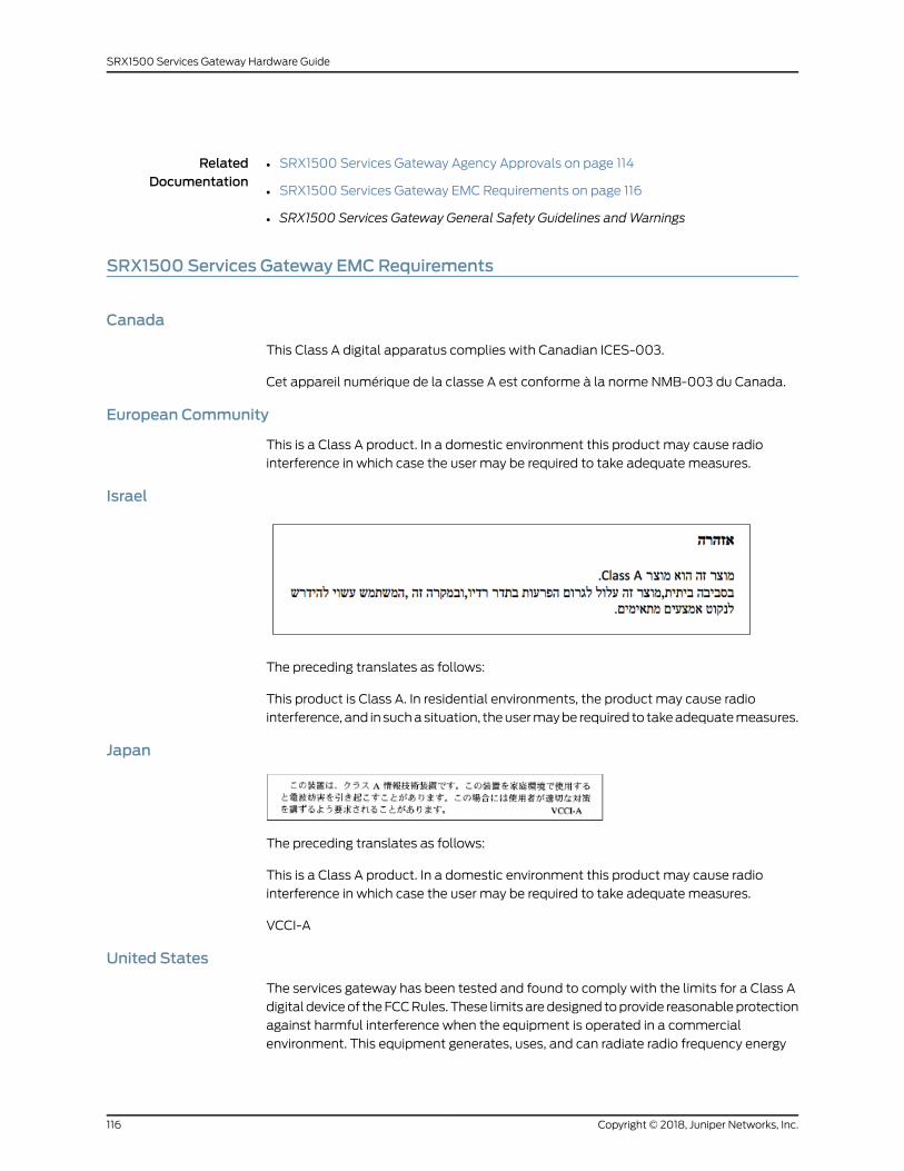
RelatedDocumentation
SRX1500 Services Gateway Agency Approvals on page 114•
• SRX1500 Services Gateway EMC Requirements on page 116
• SRX1500 Services Gateway General Safety Guidelines andWarnings
SRX1500 Services Gateway EMCRequirements
Canada
This Class A digital apparatus complies with Canadian ICES-003.
Cet appareil numérique de la classe A est conforme à la norme NMB-003 du Canada.
European Community
This is a Class A product. In a domestic environment this product may cause radio
interference in which case the user may be required to take adequate measures.
Israel
The preceding translates as follows:
This product is Class A. In residential environments, the product may cause radio
interference, and in suchasituation, theusermaybe required to takeadequatemeasures.
Japan
The preceding translates as follows:
This is a Class A product. In a domestic environment this product may cause radio
interference in which case the user may be required to take adequate measures.
VCCI-A
United States
The services gateway has been tested and found to comply with the limits for a Class A
digital deviceof theFCCRules. These limits aredesigned toprovide reasonableprotection
against harmful interference when the equipment is operated in a commercial
environment. This equipment generates, uses, and can radiate radio frequency energy
Copyright © 2018, Juniper Networks, Inc.116
SRX1500 Services Gateway Hardware Guide
and, if not installed and used in accordance with the instruction manual, may cause
harmful interference to radiocommunications.Operationof this equipment ina residential
area is likely to cause harmful interference in which case the user will be required to
correct the interference at his own expense.
RelatedDocumentation
• SRX1500 Services Gateway Agency Approvals on page 114
• SRX1500 Services Gateway Acoustic Noise Compliance Statements on page 115
• SRX1500 Services Gateway General Safety Guidelines andWarnings
117Copyright © 2018, Juniper Networks, Inc.
Chapter 7: Safety and Compliance Information

Copyright © 2018, Juniper Networks, Inc.118
SRX1500 Services Gateway Hardware Guide