Embed Size (px)
Citation preview
IMPORTANT NOTICE
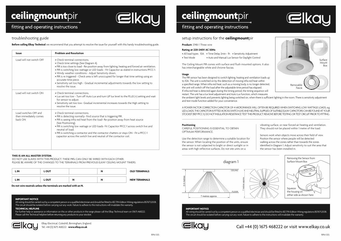
setup instructions for the ceilingmountpir
Product: 374B-1 Three wire
Rating at 220-240V AC 50Hz• All load types 10A • Time Delay 2min - 1h • Sensitivity Adjustment• Test Mode • Auto and Manual Lux Sensor for Daylight Control
Call +44 (0) 1675 468222 or visit www.elkay.co.uk
fitting and operating instructions
ceilingmountpirfitting and operating instructions
ceilingmountpir
Removing the Sensor fromSurface Mount Box
Squeeze the housing on either side as shown here
diagram 1
The Ceiling Mount PIR comes with surface and flush mounted options. It alsohas interchangeable white and chrome fascias.
Usage The PIR sensor has been designed to switch lighting, heating and ventilation loads upto 10A. The unit is switched on by the detection of moving infra red heat within a specified range. When infra red heat, such as a moving body, is no longer detected,the unit will switch off the load after the adjustable time period has elapsed. If infra red heat is detected again during the timing period, the timing sequence willrestart. The unit has a lux level adjustment and Auto Lux function, which measuresthe ambient light levels and prevents lighting being switched on, when there is sufficient lighting in the room. There is sensitivity adjustmentand test mode function added for your convenience.
A POWER FACTOR CORRECTION CAPACITOR OF 4 MICROFARADS WILL OFTEN BE REQUIRED WHEN SWITCHING LOW WATTAGE LOADS, e.g.LED LOADS. THE CAPACITOR IS FITTED ACROSS SWITCH LIVE AND NEUTRAL SUPPLIES OF SUITABLE ELKAY CAPACITORS CAN BE FOUND AT YOURSTOCKIST (REF PFCC-1). DO NOT INSULATION RESISTANCE TEST THIS PRODUCT. REMOVE BEFORE TESTING OR TEST CIRCUIT PRIOR TO FITTING.
PositioningCAREFUL POSITIONING IS ESSENTIAL TO OBTAIN OPTIMUM PERFORMANCE.
Use the detection range to determine a suitable location forthe sensor. When locating the position of the units, ensurethe sensor is not subjected to bright or direct sunlight or inareas with high reflective surfaces. Do not site units on a
vibrating surface, or near forced air heating and ventilation.They should not be placed within 1 metre of the load.
Sensors work when objects move across their field of view.Position the sensor where people will be detected walking across the zones rather than towards the zones identified in Diagram 1. Adjust sensitivity to suit the area thatthe sensor has been installed in.
IMPORTANT NOTICEAll wiring should be carried out by a competent person or a qualified electrician and should be fitted to IEE 17th Edition Wiring regulations BS7671:2008.The circuit should be isolated before carrying out any work. Failure to adhere to the instructions will invalidate the warranty.TECHNICAL HELPLINEFor further help or assistance or information on this or other products in the range please call the Elkay Technical team on 01675 468222. Please call the Technical helpline before returning any products to your stockist.
Elkay Electrical, Coleshill, Birmingham, England.Tel: +44 (0) 1675 468222 www.elkay.co.uk
RPM 305
IMPORTANT NOTICEAll wiring should be carried out by a competent person or a qualified electrician and should be fitted to IEE 17th Edition Wiring regulations BS7671:2008.The circuit should be isolated before carrying out any work. Failure to adhere to the instructions will invalidate the warranty.
SurfaceMount
Box
RemovableFascia
troubleshooting guideBefore calling Elkay Technical we recommend that you attempt to resolve the issue for yourself with this handy troubleshooting guide.
Issue Problem and Resolution
Load will not switch OFF • Check terminal connections.• Check time settings (See Diagram 4).• PIR is too close to load - Re-position away from lighting, heating and forced air ventilation.• PIR is switching low wattage or LED loads - Fit Capacitor as stated in instructions PFCC-1.• Windy weather conditions - Adjust Sensitivity down.• PIR is re triggered - Check area is left unoccupied for longer that time setting using an
accurate time piece.• Sensitivity set too high - Gradual incremental adjustments towards the low setting to
resolve the issue.
Load will not switch ON • Check terminal connections.• Lux set too low - Turn off Auto Lux and turn UP lux level to the PLUS (+) setting and wait
for sensor to adjust.• Sensitivity set too low- Gradual incremental increases towards the High setting to
resolve the issue.
Load switches OFF and • Check terminal connections.then immediately comes • PIR is detecting normally- Find source that is triggering PIR.back ON • PIR is seeing infra red heat from the load- Re-position away from heat source
(See Positioning).• PIR is switching low wattage or LED loads- Fit Capacitor PFCC-1 across switch live and
neutral of load.• PIR is switching a contactor and the contactor chatters or stays ON - Fit a PFCC-1
capacitor across the switch live and neutral of the contactor coil.
THIS IS AN ALL MASTER SYSTEM. DO NOT USE SLAVES WITH THIS PRODUCT. THESE PIR’s CAN ONLY BE WIRED WITH EACH OTHER.PLEASE BE AWARE OF THE CHANGES TO THE TERMINALS FROM PREVIOUS ELKAY CEILING MOUNT TIMERS.
L IN L OUT N OLD TERMINALS
L IN L OUT N N NEW TERMINALS
Do not wire neutrals unless the terminals are marked with an N.
RPM 305
7 m
etre
s ap
prox
.
2.4
met
res
7 metres approx.
CEILING
FLOOR
IMPORTANT NOTICEAll wiring should be carried out by a competent person or a qualified electrician and should be fitted to IEE 17th Edition Wiring regulations BS7671:2008.The circuit should be isolated before carrying out any work. Failure to adhere to the instructions will invalidate the warranty.
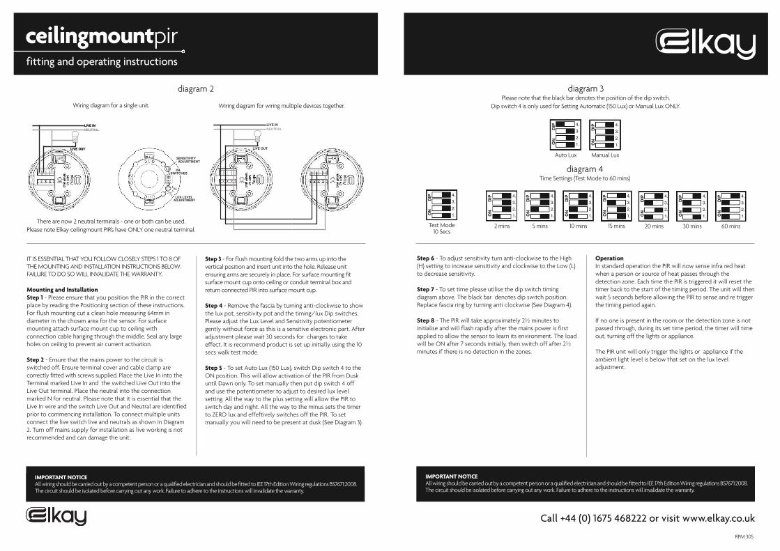
diagram 3Please note that the black bar denotes the position of the dip switch.
Dip switch 4 is only used for Setting Automatic (150 Lux) or Manual Lux ONLY.
4.
3.
2.
1.
4.
3.
2.
1.
4.
3.
2.
1.
4.
3.
2.
1.
4.
3.
2.
1.
ON
DIP
ON
DIP
ON
DIP
ON
DIP
ON
DIP
Manual Lux
2 mins 5 mins 10 mins 15 mins
4.
3.
2.
1.
4.
3.
2.
1.
4.
3.
2.
1.ON
DIP
ON
DIP
ON
DIP
20 mins 30 mins 60 mins
LIVE IN
LIVE OUT
NEUTRALLIVE IN
LIVE OUT
NEUTRAL
LUX LEVEL ADJUSTMENT
SENSITIVITY ADJUSTMENT
DIL SWITCHES
Wiring diagram for a single unit. Wiring diagram for wiring multiple devices together.
LIVE IN
LIVE OUT
NEUTRAL
fitting and operating instructions
ceilingmountpir
IMPORTANT NOTICE
Call +44 (0) 1675 468222 or visit www.elkay.co.uk
IMPORTANT NOTICEAll wiring should be carried out by a competent person or a qualified electrician and should be fitted to IEE 17th Edition Wiring regulations BS7671:2008.The circuit should be isolated before carrying out any work. Failure to adhere to the instructions will invalidate the warranty.
IT IS ESSENTIAL THAT YOU FOLLOW CLOSELY STEPS 1 TO 8 OFTHE MOUNTING AND INSTALLATION INSTRUCTIONS BELOW. FAILURE TO DO SO WILL INVALIDATE THE WARRANTY.
Mounting and InstallationStep 1 - Please ensure that you position the PIR in the correctplace by reading the Positioning section of these instructions.For flush mounting cut a clean hole measuring 64mm indiameter in the chosen area for the sensor. For surfacemounting attach surface mount cup to ceiling withconnection cable hanging through the middle. Seal any largeholes on ceiling to prevent air current activation.
Step 2 - Ensure that the mains power to the circuit isswitched off. Ensure terminal cover and cable clamp arecorrectly fitted with screws supplied. Place the Live In into theTerminal marked Live In and the switched Live Out into theLive Out terminal. Place the neutral into the connectionmarked N for neutral. Please note that it is essential that theLive In wire and the switch Live Out and Neutral are identifiedprior to commencing installation. To connect multiple unitsconnect the live switch live and neutrals as shown in Diagram2. Turn off mains supply for installation as live working is notrecommended and can damage the unit.
Step 3 - For flush mounting fold the two arms up into thevertical position and insert unit into the hole. Release unitensuring arms are securely in place. For surface mounting fitsurface mount cup onto ceiling or conduit terminal box andreturn connected PIR into surface mount cup.
Step 4 - Remove the fascia by turning anti-clockwise to showthe lux pot, sensitivity pot and the timing/lux Dip switches.Please adjust the Lux Level and Sensitivity potentiometergently without force as this is a sensitive electronic part. Afteradjustment please wait 30 seconds for changes to takeeffect. It is recommend product is set up initially using the 10secs walk test mode.
Step 5 - To set Auto Lux (150 Lux), switch Dip switch 4 to theON position. This will allow activation of the PIR from Duskuntil Dawn only. To set manually then put dip switch 4 offand use the potentiometer to adjust to desired lux levelsetting. All the way to the plus setting will allow the PIR toswitch day and night. All the way to the minus sets the timerto ZERO lux and effeftively switches off the PIR. To setmanually you will need to be present at dusk (See Diagram 3).
Step 6 - To adjust sensitivity turn anti-clockwise to the High(H) setting to increase sensitivity and clockwise to the Low (L)to decrease sensitivity.
Step 7 - To set time please utilise the dip switch timingdiagram above. The black bar denotes dip switch position.Replace fascia ring by turning anti clockwise (See Diagram 4).
Step 8 - The PIR will take approximately 2½ minutes toinitialise and will flash rapidly after the mains power is firstapplied to allow the sensor to learn its environment. The loadwill be ON after 7 seconds initially, then switch off after 2½minutes if there is no detection in the zones.
OperationIn standard operation the PIR will now sense infra red heatwhen a person or source of heat passes through thedetection zone. Each time the PIR is triggered it will reset thetimer back to the start of the timing period. The unit will thenwait 5 seconds before allowing the PIR to sense and re triggerthe timing period again.
If no one is present in the room or the detection zone is notpassed through, during its set time period, the timer will timeout, turning off the lights or appliance.
The PIR unit will only trigger the lights or appliance if theambient light level is below that set on the lux leveladjustment.
4.
3.
2.
1.ON
DIP
Test Mode10 Secs
4.
3.
2.
1.ON
DIP
Auto Lux
diagram 2
diagram 4Time Settings (Test Mode to 60 mins)
RPM 305
There are now 2 neutral terminals - one or both can be used. Please note Elkay ceilingmount PIR’s have ONLY one neutral terminal.