Embed Size (px)
Citation preview

SRS Deliverable 4.1.2 Due date: 30 March 2013
FP7 ICT Contract No. 247772 1 February 2010 – 30 April 2013 Page 1 of 59
DELIVERABLE: D4.1.2
Name of the Deliverable: Integrated report about SRS control
programme and safety assurance
Contract number : 247772
Project acronym : SRS
Project title : Multi-Role Shadow Robotic System for Independent Living
Deliverable number : D4.1.2
Nature : Final
Dissemination level : PU – Public
Delivery date :
Author(s) : Noyvirt, Arbeiter, Qiu, Ji, Li, Kronreif, Angelov, Lopez, Rooker
Partners contributed : CU, IPA, BED,ISER-BAS, HPIS,PROFACTOR, IMA, ROB
Contact : Dr. Renxi Qiu, MEC, Cardiff School of Engineering, Cardiff University, Queen’s Buildings, Newport Road, Cardiff CF24 3AA, United Kingdom
Tel: +44(0)29 20875915; Fax: +44(0)29 20874880; Email: [email protected]
SRS
Multi‐Role Shadow Robotic System for Independent Living
Small or medium scale focused research project (STREP)
The SRS project is funded by the European Commission under the 7th Framework Programme (FP7) – Challenges 7: Independent living, inclusion and Governance Coordinator: Cardiff University
SRS
Multi‐Role Shadow Robotic System for Independent Living
Small or medium scale focused research project (STREP)
SRS Deliverable 4.1.2 Due date: 30 March 2013
FP7 ICT Contract No. 247772 1 February 2010 – 30 April 2013 Page 2 of 59
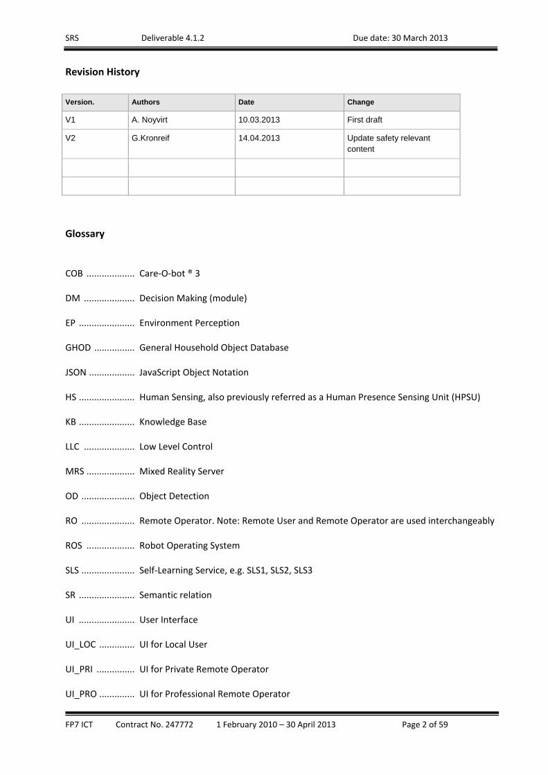
Revision History
Version. Authors Date Change
V1 A. Noyvirt 10.03.2013 First draft
V2 G.Kronreif 14.04.2013 Update safety relevant content
Glossary
COB ................... Care‐O‐bot ® 3
DM .................... Decision Making (module)
EP ...................... Environment Perception
GHOD ................ General Household Object Database
JSON .................. JavaScript Object Notation
HS ...................... Human Sensing, also previously referred as a Human Presence Sensing Unit (HPSU)
KB ...................... Knowledge Base
LLC .................... Low Level Control
MRS ................... Mixed Reality Server
OD ..................... Object Detection
RO ..................... Remote Operator. Note: Remote User and Remote Operator are used interchangeably
ROS ................... Robot Operating System
SLS ..................... Self‐Learning Service, e.g. SLS1, SLS2, SLS3
SR ...................... Semantic relation
UI ...................... User Interface
UI_LOC .............. UI for Local User
UI_PRI ............... UI for Private Remote Operator
UI_PRO .............. UI for Professional Remote Operator
SRS Deliverable 4.1.2 Due date: 30 March 2013
FP7 ICT Contract No. 247772 1 February 2010 – 30 April 2013 Page 3 of 59
Executive Summary
The work in WP4, “Technology Integration on Shadow Robotic System” has been focused on bringing several different technologies together in a single system. These technologies include several SRS software modules, contributed by the technical partners in the SRS project, and other open source software modules that have been identified as needed for the efficient functioning SRS system. The SRS developed modules include: three user interfaces (UI_LOC, UI_PRI and UI_PRO), a knowledge base, a decision making module, an object perception module, a human sensing module, a learning module and an object database. The software modules, together with the Care‐O‐Bot 3 hardware platform form the basis of a fully operational robotic system that is able to provide a number of essential elderly care giving services for prolonging the independent living at home. The range of care‐giving services, available through the SRS platform, includes a number of everyday living support functions like: fetching different objects, monitoring of the condition of the elderly and facilitating communication between the elderly person and relatives or care‐workers. The support functions, identified as relevant in the user studies at the beginning of the project, have been clustered in a number of SRS scenarios. The functions selected within a scenario are based on the prioritized needs of the elderly user, as reported by them or by close family members in the user studies carried out in the project. Also the scenarios have been assessed and fine‐tuned from several safety and technology related perspectives to be within the range of the possible actions that service robots can currently execute without putting the elderly users in any risk. Although WP4 is focussed mainly on the integration of different software modules, the work carried out in this workpackage also represents a continuation to the research activities done in WP3. In particular, a number of algorithms researched in WP3 have been further enhanced, tested and put in practice. An additional aspect of WP4 has been the investigation of the safety aspects of the robotic system as a whole. This document covers the implementation of the safety assurance aspects related to the SRS system. These aspects have been thoroughly investigated and implemented alongside the main integration activities. In WP4 of SRS, the technical partners have carried out the work activities related to integration of components and resulting in a robotic system capable to execute scenarios. The work has been focused on satisfying the specification requirements, that were set at the beginning of the project. The development process has involved a number of development cycles and system tests on different system levels as follows: at component level, tests have been carried out to evaluate the functionality of a pairs of interlinked components; at system level, tests have been carried out to establish how well the SRS scenarios can be executed and how robustly the system is performing under challenging circumstances. For timely achievement of the project objectives, the consortium partners in WP4 have adopted the Continuous Integration (CI) approach. It has allowed them to eliminate early many of the problems, normally associated with the development of complex software systems, without suffering significant disruption to work. At the same time, CI has led to noticeable acceleration of the development process and significant time savings within the project. Additionally, the integration process has been facilitated by the active usage of a shared software repository, i.e. GitHub. The online code versioning system has allowed the software developing partners, distributed across Europe, to manage code versioning effectively and to integrate early and often. This has led to reduction in the need of rework or major changes at later stages of the project.

SRS Deliverable 4.1.2 Due date: 30 March 2013
FP7 ICT Contract No. 247772 1 February 2010 – 30 April 2013 Page 4 of 59
A number of on‐site integration sessions have allowed evaluation of the developed software to be done on the real robotic platform. The integration sessions have included a number of test units done in a simulated home environment, i.e. the IPA kitchen, which has been specifically designed to be as close as possible to the real home environments where the robot would operate. Moreover, on several occasions the robotic platform has been transported to a real home of elderly people and deployed to confirm the results of the tests in the simulated home environment. This has allowed any additional issues, manifesting only under real environment deployment, to be observed and addressed. As a result, the majority of the problems, detected in the real environment tests, have been identified early in the project life span and addressed within its duration. The on‐site integration sessions have been organised to check the integration progress according to a specific pre‐defined integration testing criteria. The integration process at these sessions normally followed a template sequence that has been agreed by the project consortium members in advance. An example of such a sequence typically would include : (a) testing of the modules in couples; (b) testing of the whole system and (c) testing with users. After each integration session, an action plan, aimed to guide the further efforts of all technical partners until the next integration session, was drawn and agreed by the project partners. The action plan has been based on the issues identified during the integration session as well as on the general direction of the SRS system development according to the project plan. In the second part of the project, integration meetings for preparation of the user test have been also been organised before each set of the user tests. This has helped eliminating the majority of technical glitches that could hinder the execution of the user test as the pressures in user tests does not allow time for sorting technical problems. The progress between the integration sessions has been measured against the agreed action plan and any deviations have been investigated. Workpackage WP4 is one of the workpackages in the SRS project where the safety issues for the SRS system have been addressed. The safety measures reported in this document are based on the safety methodology developed in WP2, as well as on the safety analysis and proposed countermeasures carried out in WP1. Overall, the safety framework consists of a number of selected mitigation measures and their practical implementation guidelines. In conclusion, the SRS system has been built by the consortium partners in WP4 through integration of separate software technologies working on top of the Care‐O‐Bot 3 hardware platform. The whole system has been extensively tested, both in a simulated home environment and real user tests. Subsequently after each test unit, a number of improvement needs have been identified have been addressed in the software accordingly to be tested at the next integration session.
SRS Deliverable 4.1.2 Due date: 30 March 2013
FP7 ICT Contract No. 247772 1 February 2010 – 30 April 2013 Page 5 of 59
TableofContents1. Introduction ...................................................................................................................................... 8
2. OverallStructureoftheSRSsystem ............................................................................................. 9
3. SRSsystemcomponents ............................................................................................................... 14
IntendBasedRemoteControlStrategiesandAdaptiveautonomy .............................................. 17
IntentBasedRemoteControlStrategies ........................................................................................ 17
SemanticKnowledgeRepresentation ............................................................................................ 20
SRShighlevelcommandsandtranslation ..................................................................................... 21
Texturedbasedobjectdetection..................................................................................................... 25
Shapebasedobjectdetection .......................................................................................................... 26
SafetyinSRS ..................................................................................................................................... 34
SRSSafetyAnalysis .......................................................................................................................... 35
SafetySystem ................................................................................................................................... 37
Changeofoperationmodesandtransferofcontrol...................................................................... 39
HumanSensing ................................................................................................................................. 40
Humantrackanalysis ...................................................................................................................... 43
RobotArmCollisionAvoidance ...................................................................................................... 47
Safetyrelatedimprovementsofthefoldabletrayandarm .......................................................... 48
Controlandcommunication ............................................................................................................ 48
SRSMixedrealityserver .................................................................................................................. 49
Openinterfacedesignconcepts ...................................................................................................... 52
Functionaldescription ..................................................................................................................... 52
Theobjectdatastorage ................................................................................................................... 53
TheFileRepository .......................................................................................................................... 55
4. SRSGeneralFramework‐implementationandintegrationprocess .................................. 55
5. Validation ........................................................................................................................................ 56
6. References: ...................................................................................................................................... 58
7. Appendixes ...................................................................................................................................... 59
AppendixA:ResearchPublicationsfromtheSRSProject ............................................................. 59
SRS Deliverable 4.1.2 Due date: 30 March 2013
FP7 ICT Contract No. 247772 1 February 2010 – 30 April 2013 Page 6 of 59
ListofFigures Figure 1: Architecture of the SRS system. .................................................................................................. 11 Figure 2: Semi‐autonomous mode of operation in SRS ............................................................................. 15 Figure 3: DM high level overview ............................................................................................................... 16 Figure 4: State Machine of DM with possible states ................................................................................. 16 Figure 5: Action sequence of opening a door ........................................................................................... 17 Figure 6: Tested scenarios in SRS ............................................................................................................... 19 Figure 7: Robot self‐learning ..................................................................................................................... 20 Figure 8: Information exchange between the KB and the rest of the modules ......................................... 21 Figure 9: Iterative calls to the “Plan next” action service .......................................................................... 22 Figure 10: Object detection based on texture. .......................................................................................... 25 Figure 11: Display of the detected object in the UI_PRI interface ............................................................. 26 Figure 12: Object detection algorithm via shape reconstruction ............................................................. 27 Figure 13: Computation and simulation of the best grasp points ............................................................. 29 Figure 14: Grasp action sequence state machine ...................................................................................... 30 Figure 15: Overall grasp sequence diagram .............................................................................................. 31 Figure 16: Learning from action sequence of the remote operators, SLS1 ............................................... 33 Figure 17: Different rule based grasp configurations given by SLS2 for two objects, X and Y ................... 33 Figure 18: Rule generation in self‐learning service .................................................................................... 34 Figure 19: “SAFETY” IN SRS PROJECT ......................................................................................................... 35 Figure 20: Risk management matrix (example) ......................................................................................... 36 Figure 21: FMEA for selected risks (example) ........................................................................................... 37 Figure 22: Basic design of the proposed “Safety Board”........................................................................... 38 Figure 23: Safety functions UI_LOC – Screenshots. ................................................................................... 40 Figure 24: Human detection from laser range data. .................................................................................. 42 Figure 25: Information exchange mechanism between the HS and the rest of the modules ................... 43 Figure 26: Association of measurements to human tracks ........................................................................ 45 Figure 27: Example of possible data associations combinations between tracks, detections and clutter 45 Figure 28: The effect of a single wrong data association and crossing of tracks ....................................... 45 Figure 29: The results of human track reconstruction algorithm. ............................................................. 47 Figure 30: Diagram of the Mixed Reality Server and its subcomponents .................................................. 50 Figure 31: Output of the Mixed Reality Server .......................................................................................... 51 Figure 32: Mechanism of storing and retrieving information in GHOD ..................................................... 53 Figure 33: Tables and their fields in GHOD ............................................................................................... 54 Figure 34: The structure of the file repository ......................................................................................... 55
SRS Deliverable 4.1.2 Due date: 30 March 2013
FP7 ICT Contract No. 247772 1 February 2010 – 30 April 2013 Page 7 of 59
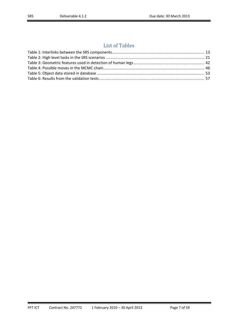
ListofTablesTable 1: Interlinks between the SRS components ...................................................................................... 13 Table 2: High level tasks in the SRS scenarios ............................................................................................ 21 Table 3: Geometric features used in detection of human legs .................................................................. 42 Table 4: Possible moves in the MCMC chain .............................................................................................. 46 Table 5: Object data stored in database .................................................................................................... 53 Table 6: Results from the validation tests .................................................................................................. 57

SRS Deliverable 4.1.2 Due date: 30 March 2013
FP7 ICT Contract No. 247772 1 February 2010 – 30 April 2013 Page 8 of 59
1. Introduction
The work in WP4 has been focused on the design, implementation and integration of the software
modules that are forming the basis of the SRS system. Each of the technical partners, depending on
their area of expertise and responsibilities in the project, has been allocated the development of one or
more software modules. Since all of the modules in the SRS system are interlinked and exchange
information extensively between one another, they had to be designed and developed collaboratively in
a way that guarantees their optimal performance in an integrated system. The “sandbox” development
of the software has started early, in WP3, alongside the research activities. Later, in WP4, the
development has been ramped up and the focus has shifted from more research aspects to “pre‐
production” implementation of the proposed in WP3 algorithms. For this purpose they the software
modules have been further improved, tested and continuously refined so that a full integration into a
coherent system could be feasible. Moreover, regular tests have been carried out at different levels
with the understanding that the system and acceptance testing are essential part of the process of
system development.
The collaborative development has been further supported by the use of a shared repository, i.e.
GitHub1, which has been used as a tool for rapid collaboration between the partners and peer review of
the software. The developers from each partner organisation, after unit testing, had been publishing
their latest software release to the shared repository for peer review from the others in the project. In
order to reduce integration time and cost at later stage the Care‐O‐Bot simulation has been used
extensively by the individual partners before submitting code to the shared repository. This has allowed
most of the newly developed features to be tested and debugged before moving to real test on the
hardware platform, i.e. Care‐O‐Bot. As a result of using the simulation for testing of the software, before
the actual test on the hardware platform, substantial time saving has been achieved in the project. After
each of the testing‐debugging‐refining cycles had finished, reaching a stage at which all technical
problems have been deemed to be successfully addressed, the testing of the whole system was shifted
to the COB hardware platform for real test in a integration meeting. Such an approach has allowed the
elimination of small technical glitches at first stage of each development cycle and enabled the full
system functional tests, aimed at identification of more fundamental problems, to be carried out at the
final stage of the development cycle.
For better clarity of this document, the work done in SRS is reported by task as described in the DoW.
Brief integration overview and technical notes about the system as a whole are also provided at the end
of the document.
1 http://en.wikipedia.org/wiki/GitHub

SRS Deliverable 4.1.2 Due date: 30 March 2013
FP7 ICT Contract No. 247772 1 February 2010 – 30 April 2013 Page 9 of 59
2. OverallStructureoftheSRSsystem
The SRS consists of several components working together and exchanging information through a ROS
infrastructure. The individual components and their functional characteristics are based on the SRS
system functional requirements. The core of the SRS system consists of the following main components:
Decision Making (DM) The DM module is the “brain of the system”. It orchestrates the control
flow and the data flows between the rest of the modules. It also acts as a bridge between high
level commands and low level control of the COB platform. This module is developed by CU.
UI_LOC – Local user interface that allows the local user to initiate a number of commands to the
robot, e.g. “Bring me water”. This module is developed by IMA.
UI_PRI – The private user interface. It allows a non‐professional remote operator, e.g.
extended family members or caregiver, to operate to the robot remotely. This interface is able
to visualize a real time video stream from the on‐board cameras of the robot. It also allows high‐
level control of the robot and manual intervention when the autonomous mode of execution
fails to accomplish the task. The module is developed by ISER‐BAS.
UI_PRO – Professional user interface. It allows full remote control, including low level remote
control. It is designed to be used by the professional remote operator service to control the SRS
system when the extended family members or care‐givers are not available or are unable to
deal with the control of the robot. The module is developed by ROB.
Human Sensing (HS) – A software module that detects the presence of a human in the vicinity of
the robot and tracks his/her movements. The location of the human is visualised on a room map
displayed on the UI_PRI and UI_PRO interfaces. The main aim is to increase the awareness of
the remote operator (RO) about the local environment in which the robot operates. The module
is developed by CU.
Environment Perception (EP) – This module processes data coming from the sensors of the
robot, detects features of the environment and builds up‐to‐date knowledge about the location
of the robot and its surroundings. This information is used in planning the navigation and
actions of the robot. The module is developed by IPA.
Grasping – This module uses information from the environment perception module, the general
household object database and the Knowledge Base (KB) to calculate the best grasping points,
the most favourable pre‐grasp position and the optimal arm trajectory for grasping an object.
The module is developed by ROB.
Object Detection (OD) – This module detects and identifies previously learned objects. The
information from the detection is used in grasping and later stored in the General Household
Object Database for future use, e.g. for faster searching for this object. The module is developed
by IPA and Profactor.
SRS Deliverable 4.1.2 Due date: 30 March 2013
FP7 ICT Contract No. 247772 1 February 2010 – 30 April 2013 Page 10 of 59
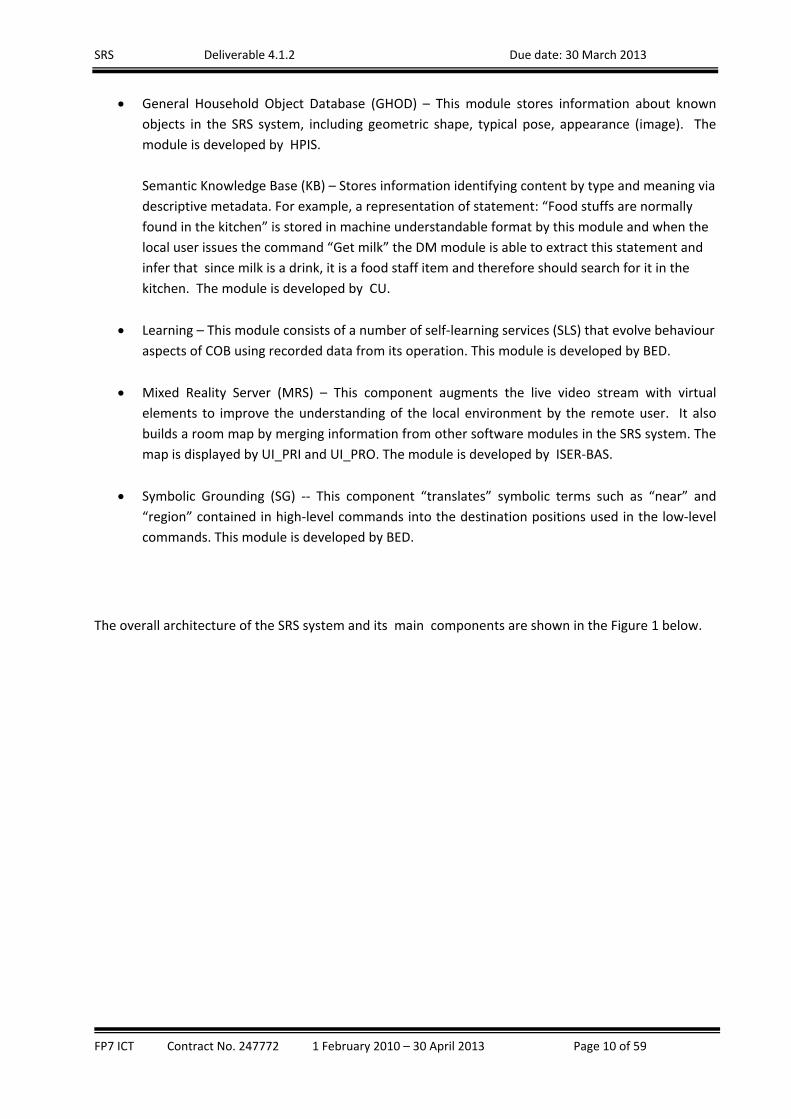
General Household Object Database (GHOD) – This module stores information about known
objects in the SRS system, including geometric shape, typical pose, appearance (image). The
module is developed by HPIS.
Semantic Knowledge Base (KB) – Stores information identifying content by type and meaning via
descriptive metadata. For example, a representation of statement: “Food stuffs are normally
found in the kitchen” is stored in machine understandable format by this module and when the
local user issues the command “Get milk” the DM module is able to extract this statement and
infer that since milk is a drink, it is a food staff item and therefore should search for it in the
kitchen. The module is developed by CU.
Learning – This module consists of a number of self‐learning services (SLS) that evolve behaviour
aspects of COB using recorded data from its operation. This module is developed by BED.
Mixed Reality Server (MRS) – This component augments the live video stream with virtual
elements to improve the understanding of the local environment by the remote user. It also
builds a room map by merging information from other software modules in the SRS system. The
map is displayed by UI_PRI and UI_PRO. The module is developed by ISER‐BAS.
Symbolic Grounding (SG) ‐‐ This component “translates” symbolic terms such as “near” and
“region” contained in high‐level commands into the destination positions used in the low‐level
commands. This module is developed by BED.
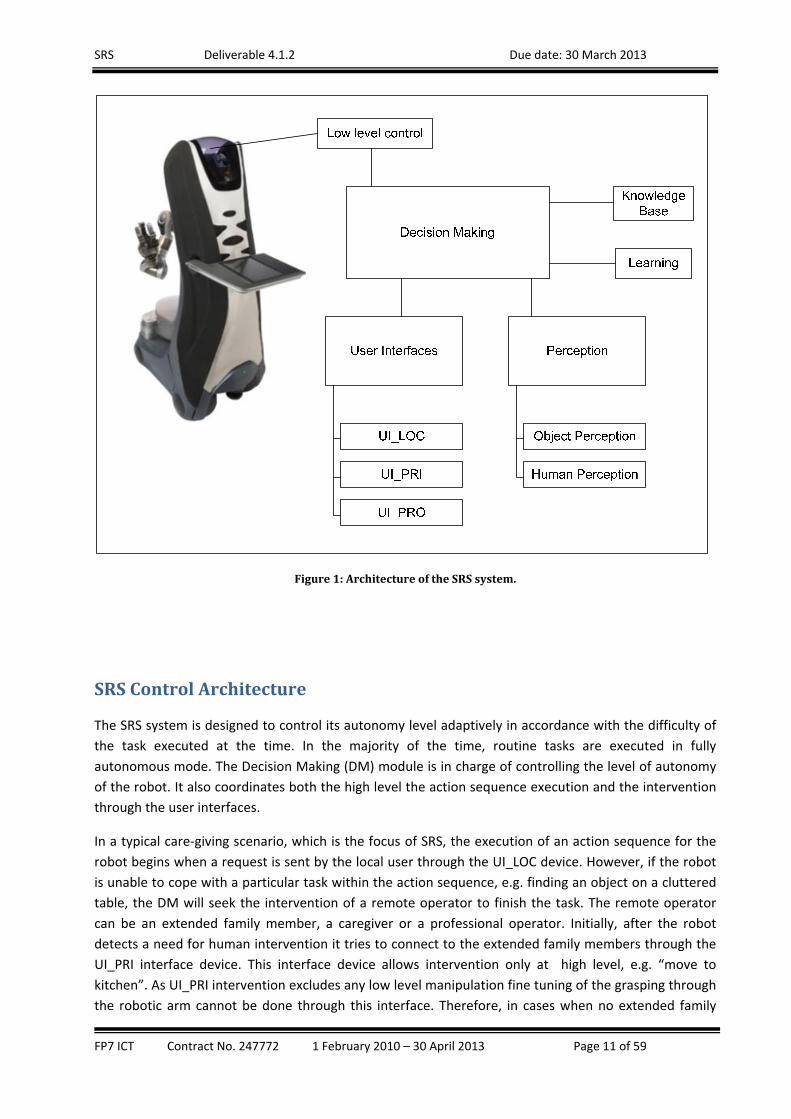
The overall architecture of the SRS system and its main components are shown in the Figure 1 below.
SRS Deliverable 4.1.2 Due date: 30 March 2013
FP7 ICT Contract No. 247772 1 February 2010 – 30 April 2013 Page 11 of 59
Figure1:ArchitectureoftheSRSsystem.
SRSControlArchitecture
The SRS system is designed to control its autonomy level adaptively in accordance with the difficulty of
the task executed at the time. In the majority of the time, routine tasks are executed in fully
autonomous mode. The Decision Making (DM) module is in charge of controlling the level of autonomy
of the robot. It also coordinates both the high level the action sequence execution and the intervention
through the user interfaces.
In a typical care‐giving scenario, which is the focus of SRS, the execution of an action sequence for the
robot begins when a request is sent by the local user through the UI_LOC device. However, if the robot
is unable to cope with a particular task within the action sequence, e.g. finding an object on a cluttered
table, the DM will seek the intervention of a remote operator to finish the task. The remote operator
can be an extended family member, a caregiver or a professional operator. Initially, after the robot
detects a need for human intervention it tries to connect to the extended family members through the
UI_PRI interface device. This interface device allows intervention only at high level, e.g. “move to
kitchen”. As UI_PRI intervention excludes any low level manipulation fine tuning of the grasping through
the robotic arm cannot be done through this interface. Therefore, in cases when no extended family

SRS Deliverable 4.1.2 Due date: 30 March 2013
FP7 ICT Contract No. 247772 1 February 2010 – 30 April 2013 Page 12 of 59
member is available or they are unable to solve the problem the control is transferred to the
professional tele‐operator service. This professional tele‐operation is carried through the professional
user interface, UI_PRO, that offers capabilities for low level control of the robot’s functions that far
exceed those of other interfaces. For example, the fine grained 3D planning of the arm‐trajectory
possible through UI_PRO, allows the user to execute virtual simulation of the arm manipulation, to
make additional corrections and then to execute the action.
The mechanism that controls dynamically the level of autonomy and decides when to involve a human
intervention is part of the Decision Making (DM) module of the robot, which is described in detail later
in this document.
SRS Deliverable 4.1.2 Due date: 30 March 2013
FP7 ICT Contract No. 247772 1 February 2010 – 30 April 2013 Page 13 of 59
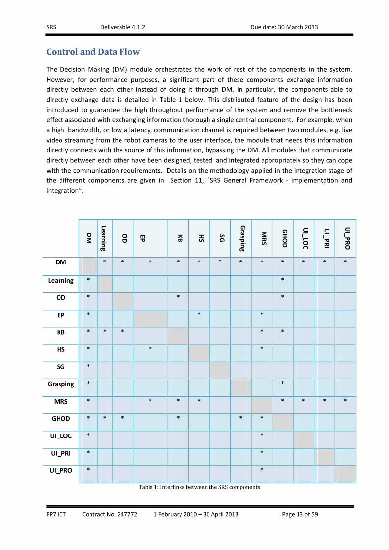
ControlandDataFlow
The Decision Making (DM) module orchestrates the work of rest of the components in the system.
However, for performance purposes, a significant part of these components exchange information
directly between each other instead of doing it through DM. In particular, the components able to
directly exchange data is detailed in Table 1 below. This distributed feature of the design has been
introduced to guarantee the high throughput performance of the system and remove the bottleneck
effect associated with exchanging information thorough a single central component. For example, when
a high bandwidth, or low a latency, communication channel is required between two modules, e.g. live
video streaming from the robot cameras to the user interface, the module that needs this information
directly connects with the source of this information, bypassing the DM. All modules that communicate
directly between each other have been designed, tested and integrated appropriately so they can cope
with the communication requirements. Details on the methodology applied in the integration stage of
the different components are given in Section 11, “SRS General Framework ‐ implementation and
integration”.
DM
Learn
ing
OD
EP
KB
HS
SG
Grasp
ing
MRS
GHOD
UI_LO
C
UI_P
RI
UI_P
RO
DM * * * * * * * * * * * *
Learning * *
OD * * *
EP * * *
KB * * * * *
HS * * *
SG *
Grasping * *
MRS * * * * * * * *
GHOD * * * * * *
UI_LOC * *
UI_PRI * *
UI_PRO * *
Table1:InterlinksbetweentheSRScomponents
SRS Deliverable 4.1.2 Due date: 30 March 2013
FP7 ICT Contract No. 247772 1 February 2010 – 30 April 2013 Page 14 of 59
Details about the implementation of the individual modules are provided in the following sections.
3. SRSsystemcomponents
AdaptiveAutonomyMechanism
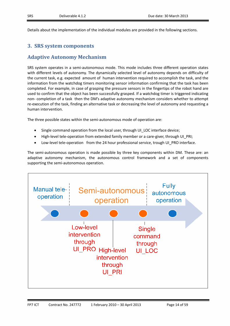
SRS system operates in a semi‐autonomous mode. This mode includes three different operation states with different levels of autonomy. The dynamically selected level of autonomy depends on difficulty of the current task, e.g. expected amount of human intervention required to accomplish the task, and the information from the watchdog timers monitoring sensor information confirming that the task has been completed. For example, in case of grasping the pressure sensors in the fingertips of the robot hand are used to confirm that the object has been successfully grasped. If a watchdog timer is triggered indicating non‐ completion of a task then the DM’s adaptive autonomy mechanism considers whether to attempt re‐execution of the task, finding an alternative task or decreasing the level of autonomy and requesting a human intervention. The three possible states within the semi‐autonomous mode of operation are:
Single command operation from the local user, through UI_LOC interface device;
High‐level tele‐operation from extended family member or a care‐giver, through UI_PRI;
Low‐level tele‐operation from the 24 hour professional service, trough UI_PRO interface.
The semi‐autonomous operation is made possible by three key components within DM. These are: an adaptive autonomy mechanism, the autonomous control framework and a set of components supporting the semi‐autonomous operation.
SRS Deliverable 4.1.2 Due date: 30 March 2013
FP7 ICT Contract No. 247772 1 February 2010 – 30 April 2013 Page 15 of 59
Figure2:Semi‐autonomousmodeofoperationinSRS The adaptive autonomy mechanism, which is implemented in the DM module, allows the system to achieve optimal balance between the automatic sequence execution and variable degree of the intervention of the remote operator when required by the circumstances. In normal operations it is not necessary for the remote operator to be involved in every action of the robot. In such circumstances the robot operates in a semi‐autonomous state that is closest to the fully autonomous operation, e.g. it executes the associated action sequence after receiving a high level command. However, there are certain times when the remote operator involvement is the only option that can help the robot out of challenging situation. Then the adaptive autonomy mechanism is in charge of decreasing the level of autonomy until a satisfactory solution is found and the robot could resume the action sequence. Therefore, in the SRS system implementation the default procedure for situations when the robot cannot cope with the current task is as follows:
initially the robot attempts to execute the initiated action sequence automatically;
If it fails, the family members are alerted and his/her intervention through the UI_PRI interfaces
is sought;
The extent of the remote intervention varies depending on the context of the situation. For
some situations it may be sufficient that the remote operator only points a new destination on
the 2D map so that a robot can avoid an obstacle on its navigation path. Also the family member
may be not available or indicate that this situation is beyond their skill level ;
If precise guidance of the robot arm is required then the adaptive autonomy mechanism
switches the mode of operation directly to the lowest level where the professional remote
operation is sought.
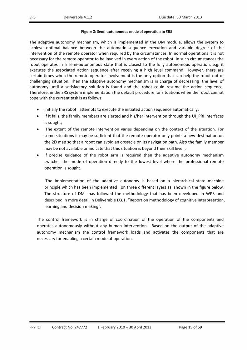
The implementation of the adaptive autonomy is based on a hierarchical state machine
principle which has been implemented on three different layers as shown in the figure below.
The structure of DM has followed the methodology that has been developed in WP3 and
described in more detail in Deliverable D3.1, “Report on methodology of cognitive interpretation,
learning and decision making”.
The control framework is in charge of coordination of the operation of the components and
operates autonomously without any human intervention. Based on the output of the adaptive
autonomy mechanism the control framework loads and activates the components that are
necessary for enabling a certain mode of operation.
SRS Deliverable 4.1.2 Due date: 30 March 2013
FP7 ICT Contract No. 247772 1 February 2010 – 30 April 2013 Page 16 of 59
Decision Level (DM)
Action Script Client (generic states)
SRS Knowledge Services
SRS high level State machines
SRS Action Server
(Interface)
Load relatedactions
Link low level commands
Robot
configuration
CompletedNot completed
High levelplanning
Task Level Primitive Action Level
Figure3:DMhighleveloverview
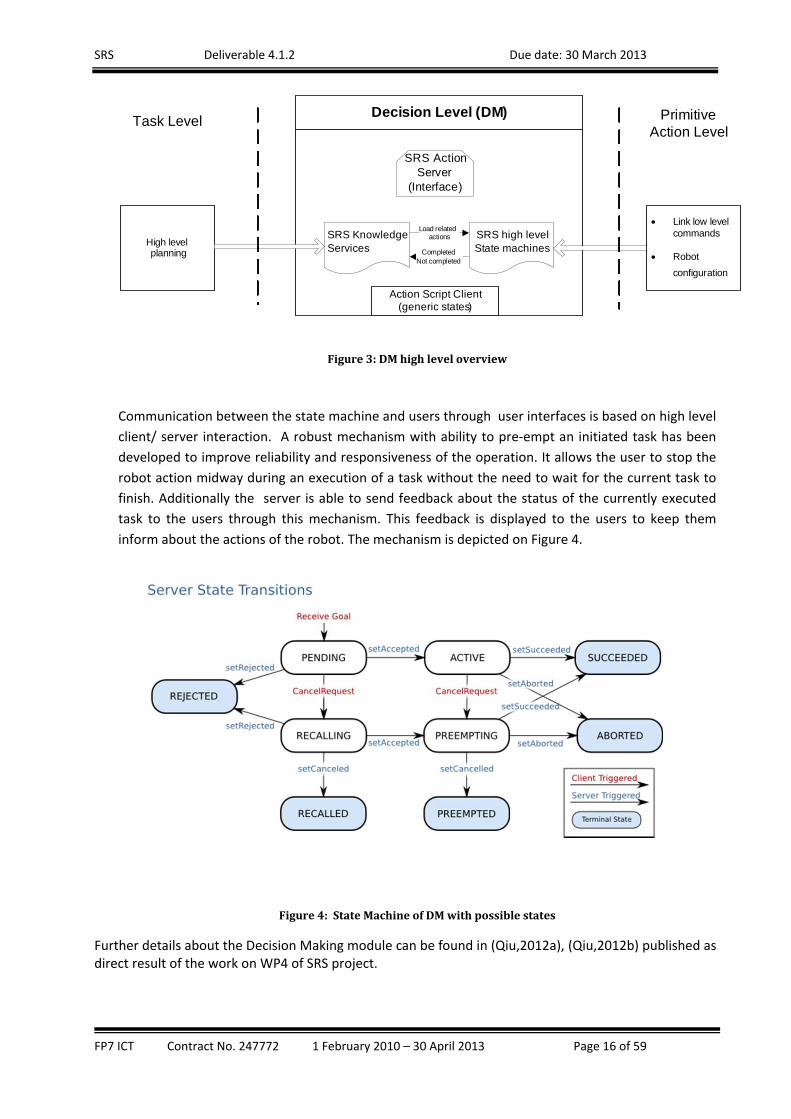
Communication between the state machine and users through user interfaces is based on high level
client/ server interaction. A robust mechanism with ability to pre‐empt an initiated task has been
developed to improve reliability and responsiveness of the operation. It allows the user to stop the
robot action midway during an execution of a task without the need to wait for the current task to
finish. Additionally the server is able to send feedback about the status of the currently executed
task to the users through this mechanism. This feedback is displayed to the users to keep them
inform about the actions of the robot. The mechanism is depicted on Figure 4.
Figure4:StateMachineofDMwithpossiblestates
Further details about the Decision Making module can be found in (Qiu,2012a), (Qiu,2012b) published as direct result of the work on WP4 of SRS project.
SRS Deliverable 4.1.2 Due date: 30 March 2013
FP7 ICT Contract No. 247772 1 February 2010 – 30 April 2013 Page 17 of 59
IntendBasedRemoteControlStrategiesandAdaptiveautonomy
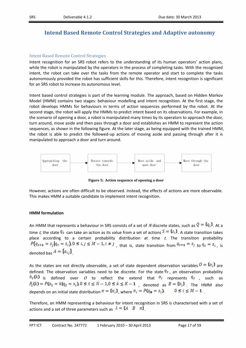
IntentBasedRemoteControlStrategiesIntent recognition for an SRS robot refers to the understanding of its human operators’ action plans, while the robot is manipulated by the operators in the process of completing tasks. With the recognized intent, the robot can take over the tasks from the remote operator and start to complete the tasks autonomously provided the robot has sufficient skills for this. Therefore, intent recognition is significant for an SRS robot to increase its autonomous level. Intent based control strategies is part of the learning module. The approach, based on Hidden Markov Model (HMM) contains two stages: behaviour modelling and intent recognition. At the first stage, the robot develops HMMs for behaviours in terms of action sequences performed by the robot. At the second stage, the robot will apply the HMMs to predict intent based on its observations. For example, in the scenario of opening a door, a robot is manipulated many times by its operators to approach the door, turn around, move aside and then pass through a door and establishes an HMM to represent the action sequences, as shown in the following figure. At the later stage, as being equipped with the trained HMM, the robot is able to predict the followed‐up actions of moving aside and passing through after it is manipulated to approach a door and turn around.
Approaching the door
Rotate towards the door
Move aside and open door
Move through the door
Figure5:Actionsequenceofopeningadoor However, actions are often difficult to be observed. Instead, the effects of actions are more observable. This makes HMM a suitable candidate to implement intent recognition. HMM formulation
An HMM that represents a behaviour in SRS consists of a set of N discrete states, such as . At a
time t, the state can take an action as its value from a set of actions . A state transition takes place according to a certain probability distribution at time t. The transition probability
, that is, state transition from to , is
denoted bas .
As the states are not directly observable, a set of state dependent observation variables are
defined. The observation variables need to be discrete. For the state , an observation probability
is defined over O to reflect the extend that represents , such as
, denoted as . The HMM also
depends on an initial state distribution , where . Therefore, an HMM representing a behaviour for intent recognition in SRS is characterised with a set of
actions and a set of three parameters such as .

SRS Deliverable 4.1.2 Due date: 30 March 2013
FP7 ICT Contract No. 247772 1 February 2010 – 30 April 2013 Page 18 of 59
Expectation maximisation EM algorithm (Dempster et al, 1977) is used to estimate the parameters of the HMM. The EM algorithm contains two steps: the E‐step, which is the calculation of the maximum likelihood of the evidence giving to the model, and the M‐step, which is the process of updating the model to maximise the probability of the evidence. Intent recognition The key issue in intent recognition in SRS using a trained HMM is to determine the current state of the action sequence, that is, the current action performed by the robot manipulated by a human operator. Based on the current state, the HMM will be able to predict an action which is the most likely one to be taken by the human operator. The forward algorithm (Zhu et al, 2008) is used to determine the most probable state that the robot is
currently at, given an HMM and an observation sequence . That is, to find a
that holds the maximum probability: After the current state is determined, the intentional state, which is the subsequent state with the highest transition probability, can be decided. Validation For validation of the above algorithms, COB has been deployed to a simulated kitchen environment and was manipulated by a human operator either to pick up a milk box that is placed on the top of a kitchen table and bring the box to the couch or to pass through a door which is near to the table. The scenario is shown in the figure below. The trajectories of the robot are presented in the figure by dashed arrows. The rotations of the robot are presented by solid arrows. In the first scenario, the robot first moved from its initial location to an area near to the kitchen table. That area is presented by a dashed circle. Then it rotated towards the milk box. After it placed the milk box on its tray, it moved to another area near to the couch. The second activity was to open the door and then move through it. In the second scenario, the robot first moved from its initial location to an area near to the door. This area is the same as the area nears to the kitchen table. Then it rotated towards the door. After the door was opened, the robot moved through the door.
SRS Deliverable 4.1.2 Due date: 30 March 2013
FP7 ICT Contract No. 247772 1 February 2010 – 30 April 2013 Page 19 of 59
Figure6:TestedscenariosinSRS
a) picking up milk box scenario; b) opening a door scenario
The following six actions were considered:
– the robot stays at its initial location
– the robot moves towards the table and the door
– the robot turns towards the milk box
– the robot turns towards the door
– the robot moves towards the couch
– the robot passes through the door In conclusion, the developed algorithm for intent based control will be integrated with the DM module and will allow through its predictive suggestions more user friendly remote control interface for UI_PRI. Robot Self‐Learning Robot Self‐Learning (RSL) records remote manipulations in terms of actions a robot performed under the manipulations and retrieves environment information. It associates the environment information with the actions as the actions’ preconditions to form a skill in the form of skill model as given in (1). This association process is discovery learning based. First, RSL captures user manipulations and environment information. Secondly, it sets up a set of hypotheses about “precondition actions” according to the captured signal. In the third step, the hypotheses serve as guidance for the robot to generate a motion plan to perform active experiments. Then, in the experiments, the robot executes the planned motions and validates the hypotheses according to the user’s response to the motions and using logical reasoning.

SRS Deliverable 4.1.2 Due date: 30 March 2013
FP7 ICT Contract No. 247772 1 February 2010 – 30 April 2013 Page 20 of 59
The overall structure of RSL is shown in Figure 1. RSL has two inputs, environment information which will be action conditions and user manipulations which can be used not only to teach robot actions but also as user feedbacks. The output of the RSL is high‐level robot skills. The 4 key blocks can be described in the followings: Condition detection module which used a heuristic based solution to detect the environment changes returned by online comparing current working environment with the environment knowledge, the detected changes will be used as action conditions. Action leaning module is used to detect user interventions and to recognize and record manipulations as robot actions, including interpreting the manipulation as high‐level robot actions and represented by the robot control system. Action learning module also serves as input to both the Hypothesis generator and Test action generator. Hypothesis generator module dealing with both action conditions and actions, for new tasks the robot has not encountered before, Hypothesis generator will set up meaningful hypothesis based on the conditions and user manipulations, for old tasks the robot has encountered before, the Hypothesis generator will use a hypothesis to guide the robot’ actions. Test action generator then takes over control of the robot during the learning process, using the hypothesis to control the robot to perform corresponding test actions to perform a task, while the Logic reasoning engine monitors and evaluates the hypothesis based on the execution of test actions and the user feedbacks, then determines whether logic reasoning is needed to speed up the hypothesis validation process.
Figure7:Robotself‐learning
RSL Logic Reasoning function is implemented using a python logic class which performs logical operations to confirm/reject hypotheses based on the observation of human intervene.
HighLevelActionRepresentationandTranslation
SemanticKnowledgeRepresentationThe Web Ontology Language (OWL) 2 is used in the SRS project for ontological knowledge
representation, in assistance to the decision making module. The semantic knowledge server is
implemented as a ROS package in the SRS stack. It has several primary services, interconnecting with
2 http://en.wikipedia.org/wiki/Web_Ontology_Language
SRS Deliverable 4.1.2 Due date: 30 March 2013
FP7 ICT Contract No. 247772 1 February 2010 – 30 April 2013 Page 21 of 59
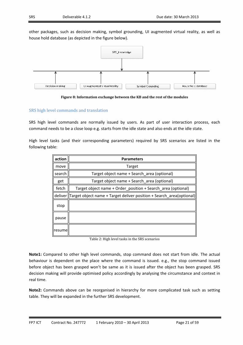
other packages, such as decision making, symbol grounding, UI augmented virtual reality, as well as
house hold database (as depicted in the figure below).
Figure8:InformationexchangebetweentheKBandtherestofthemodules
SRShighlevelcommandsandtranslation
SRS high level commands are normally issued by users. As part of user interaction process, each
command needs to be a close loop e.g. starts from the idle state and also ends at the idle state.
High level tasks (and their corresponding parameters) required by SRS scenarios are listed in the
following table:
action Parameters
move Target
search Target object name + Search_area (optional)
get Target object name + Search_area (optional)
fetch Target object name + Order_position + Search_area (optional)
deliver Target object name + Target deliver position + Search_area(optional)
stop
pause
resume
Table2:HighleveltasksintheSRSscenarios
Note1: Compared to other high level commands, stop command does not start from idle. The actual
behaviour is dependent on the place where the command is issued. e.g., the stop command issued
before object has been grasped won’t be same as it is issued after the object has been grasped. SRS
decision making will provide optimised policy accordingly by analysing the circumstance and context in
real time.
Note2: Commands above can be reorganised in hierarchy for more complicated task such as setting
table. They will be expanded in the further SRS development.
SRS Deliverable 4.1.2 Due date: 30 March 2013
FP7 ICT Contract No. 247772 1 February 2010 – 30 April 2013 Page 22 of 59
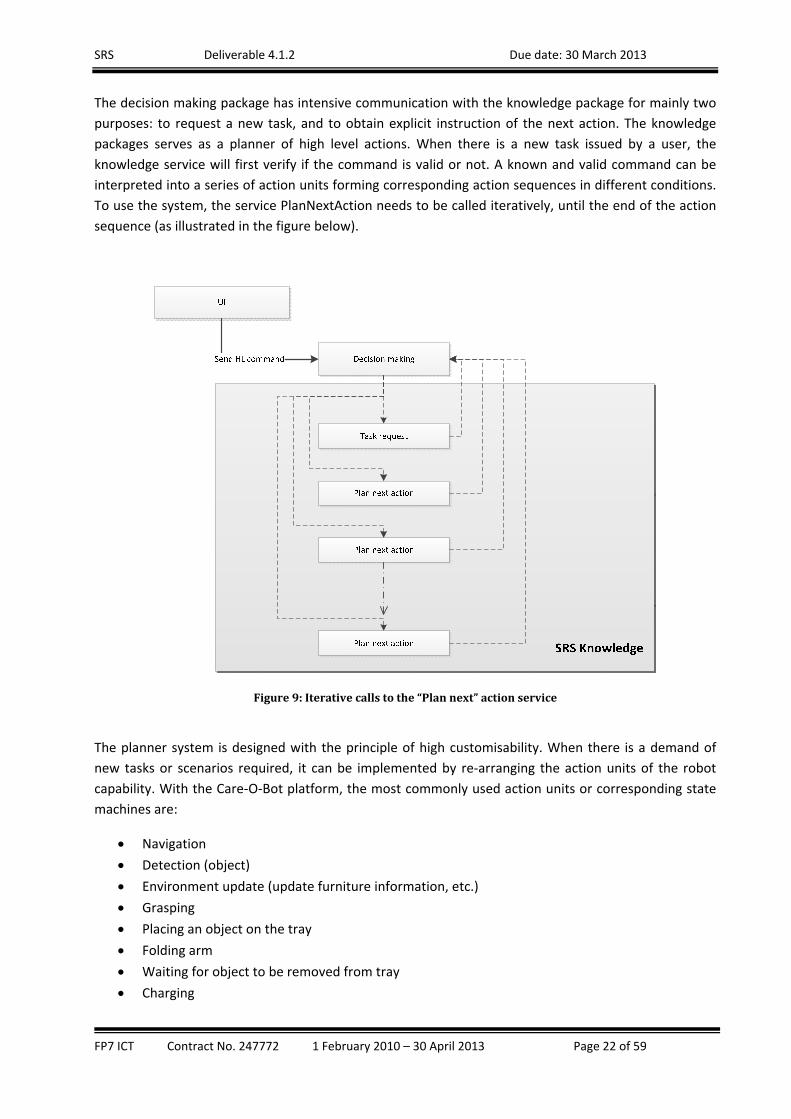
The decision making package has intensive communication with the knowledge package for mainly two
purposes: to request a new task, and to obtain explicit instruction of the next action. The knowledge
packages serves as a planner of high level actions. When there is a new task issued by a user, the
knowledge service will first verify if the command is valid or not. A known and valid command can be
interpreted into a series of action units forming corresponding action sequences in different conditions.
To use the system, the service PlanNextAction needs to be called iteratively, until the end of the action
sequence (as illustrated in the figure below).
Figure9:Iterativecallstothe“Plannext”actionservice
The planner system is designed with the principle of high customisability. When there is a demand of
new tasks or scenarios required, it can be implemented by re‐arranging the action units of the robot
capability. With the Care‐O‐Bot platform, the most commonly used action units or corresponding state
machines are:
Navigation
Detection (object)
Environment update (update furniture information, etc.)
Grasping
Placing an object on the tray
Folding arm
Waiting for object to be removed from tray
Charging

SRS Deliverable 4.1.2 Due date: 30 March 2013
FP7 ICT Contract No. 247772 1 February 2010 – 30 April 2013 Page 23 of 59
With the PlanNextAction service, the decision making module receives one of the above action units
from the knowledge module.
For example, the simplest high level command “move” accepts parameters of target in two forms:
symbolic predefined positions, such as “home”, “charging position”, or “kitchen”, and coordinates, such
as “[x, y, theta]”. Predefined positions need to be retrieved from the semantic database. Failing to do
that indicates invalid command. The actions, modelled in the knowledge database, required for this
particular task, include “navigation”, and virtual steps such as “finish_success” and “finish_fail”, which
indicate the end of task with the state of completion of the last step.
Most actions modelled in the knowledge database have corresponding state machines in the decision
making package, which are usually executable by the robot. Some of them, termed virtual actions here,
do not require any execution on the robot, but are needed to indicate either the end or the start of an
action sequence in the planner.
Other high level tasks, such as search and get, can be considered as extensions to the “move” task. In
brief, a “search” task involves a few steps, including “navigation” (to places where the target object can
be located at), “detect object”. If object is not detected, the robot will move to the next possible location
for searching until either there is no more possible place to search or the object is found. The “get
object” task basically just has one more step of “grasping” the object.
In addition, work of high level action learning has also been carried out. A fuzzy logic based approach to
the translation has been developed in the project. Taking an example of "serve me a drink", our
approach is able to translate the word "drink" to tea, coffee, water, etc. according to the context. This
will help a robot to decide what specific drink/object it should pick up. Combining this with our current
learning services, the robot can also decide where to look in order to find the drink/object. In addition,
intent recognition algorithms have been developed in the WP4 which are able to predict human
operators' intent after a robot is manipulated to complete a couple of actions by the operators.
Further details about the semantic task planning mechanism can be found in (Ji,2012) which is direct
result from the work carried out in WP4 of SRS project.
AssistedObjectDetection
The purpose of the „Assisted Object Detection Module“ is to enable a human user to help a robot in the
task of detecting objects. Normally the robot first tries to do fully autonomous detection. However,
detection may fail in various situations. For example, due to inaccurate sensor data or unsuitable
environment conditions (e.g. low or changing illumination), detection might produce false positives or
can be unable to detect anything. In this case, the human remote operator can fill the gap by manually
selecting objects in a video stream or by rejecting unwanted results.
In detail, the procedure is as follows:

SRS Deliverable 4.1.2 Due date: 30 March 2013
FP7 ICT Contract No. 247772 1 February 2010 – 30 April 2013 Page 24 of 59
1. Object detection is triggered either by the user or by the DM as part of an action sequence. A
pre‐condition for the object detection is that the robot has to be placed in front of the area of
interest (e.g. a table).
2. Before object detection is actually performed, an update of the environment map is done in
order to identify the surface where the objects can be located. This is done to check whether
the surface is there (a table could have been moved, for example) and whether the surface is
occupied at all or not. If not, the detection step on the whole can be skipped.
3. If the map update produces a positive feedback for objects on the surface, the object detection
step is started. There are two object detection methods available in SRS. The first one is able to
detect textured objects that have previously been learned. The second one is detection of
untextured objects and object classes based on their shape. More details are provided in the
subsections below.
4. The result of the object detection is passed to the user interface in a ROS message. The message
contains object pose information, object IDs and bounding boxes of the detected objects. All
these data can be used to display bounding boxes of the objects in the video stream at the
correct pose so that the user can evaluate the detection result overplayed in the live video
stream. If the result is correct (all the objects and only the objects queried have been identified
at the correct spot), the user can just accept the object detection by a context menu on the
screen and the robot continues with operation. In the case of a wrong result, e.g. false positive,
the user has the option to click on the incorrect bounding box and choose „reject“ from the
context menu. This tells the decision making module to ignore these detection results. Finally, if
detection of a wanted object failed and no bounding box is displayed on the user interface, the
user can draw a bounding box himself defining a region of interest (ROI). The defined in this way
ROI is send back to the decision making where it can be used in two ways: a) either the search
space for object detection is reduced according to the bounding box so that current detection
can achieve better recognition quality or b) the ROI is evaluated by decision making and the
robot base is re‐positioned first and subsequently a new detection is attempted. The best
approach will be evaluated in the forthcoming user tests.
In SRS two independent complementary approaches of object recognition have been taken. The first
approach relies on finding a match between key regions of the object image texture with those of
previously stored objects. The second one is based on reconstruction of 3D shape from point cloud data
and comparing it with the shapes of previously stored objects.

SRS Deliverable 4.1.2 Due date: 30 March 2013
FP7 ICT Contract No. 247772 1 February 2010 – 30 April 2013 Page 25 of 59
TexturedbasedobjectdetectionRecognition and pose estimation of textured objects is done in SRS in the following way: previously
recorded 3‐D object models are used as a base. The models consist of 2‐D feature points (BRIEF3, SURF4)
that have been mapped to 3‐D. The models are fitted to the current scene. In the first step, feature
point matching is done, followed by optimization steps in order to identify correct correspondences and
create hypothesis for object presence. Finally, PROSAC5 is applied to estimate the object's pose. For the
objects detected, a 3‐D bounding box is calculated.
Figure10:Objectdetectionbasedontexture.
3 Binary Robust Independent Elementary Features. For more details refer to (Calonder,2010) 4 Speeded Up Robust Feature, http://en.wikipedia.org/wiki/SURF 5 Progressive Sample Consensus. For more details refer to (Chum, 2005)
SRS Deliverable 4.1.2 Due date: 30 March 2013
FP7 ICT Contract No. 247772 1 February 2010 – 30 April 2013 Page 26 of 59
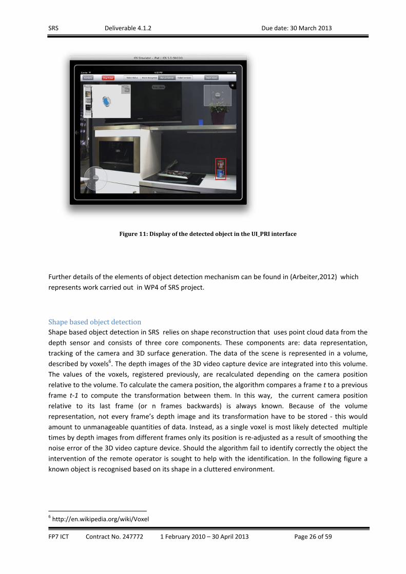
Figure11:DisplayofthedetectedobjectintheUI_PRIinterface
Further details of the elements of object detection mechanism can be found in (Arbeiter,2012) which
represents work carried out in WP4 of SRS project.
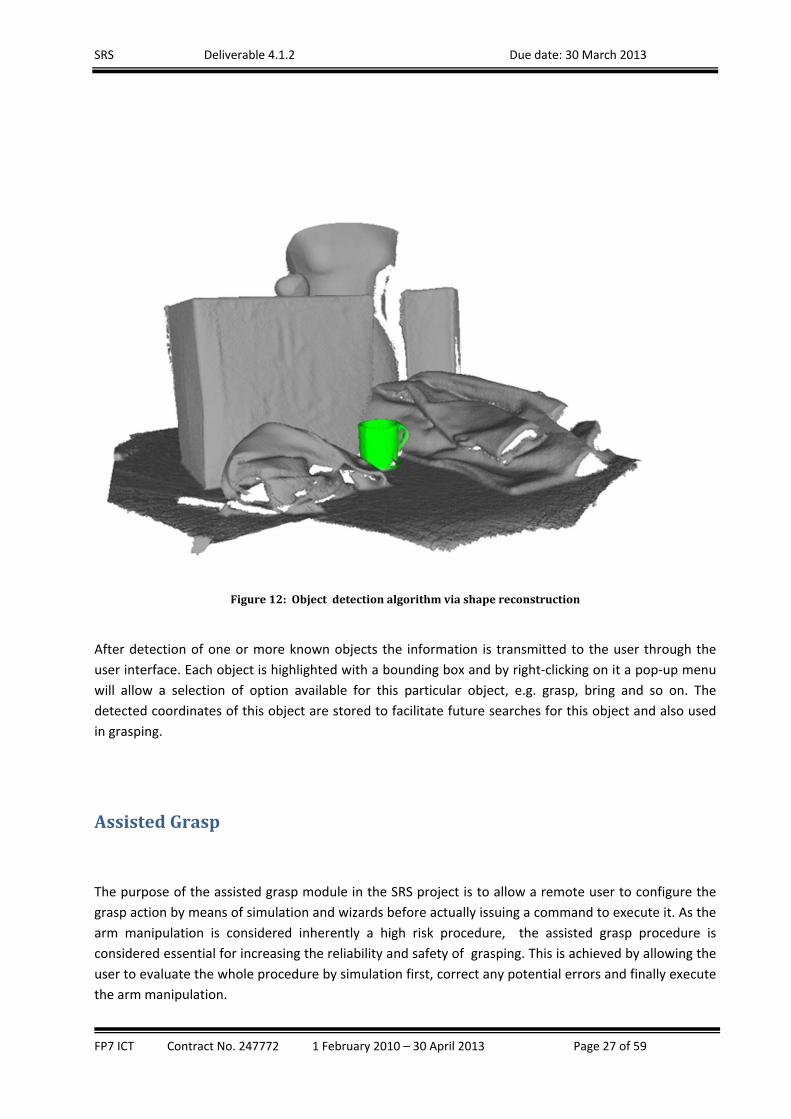
ShapebasedobjectdetectionShape based object detection in SRS relies on shape reconstruction that uses point cloud data from the
depth sensor and consists of three core components. These components are: data representation,
tracking of the camera and 3D surface generation. The data of the scene is represented in a volume,
described by voxels6. The depth images of the 3D video capture device are integrated into this volume.
The values of the voxels, registered previously, are recalculated depending on the camera position
relative to the volume. To calculate the camera position, the algorithm compares a frame t to a previous
frame t‐1 to compute the transformation between them. In this way, the current camera position
relative to its last frame (or n frames backwards) is always known. Because of the volume
representation, not every frame’s depth image and its transformation have to be stored ‐ this would
amount to unmanageable quantities of data. Instead, as a single voxel is most likely detected multiple
times by depth images from different frames only its position is re‐adjusted as a result of smoothing the
noise error of the 3D video capture device. Should the algorithm fail to identify correctly the object the
intervention of the remote operator is sought to help with the identification. In the following figure a
known object is recognised based on its shape in a cluttered environment.
6 http://en.wikipedia.org/wiki/Voxel
SRS Deliverable 4.1.2 Due date: 30 March 2013
FP7 ICT Contract No. 247772 1 February 2010 – 30 April 2013 Page 27 of 59
Figure12:Objectdetectionalgorithmviashapereconstruction
After detection of one or more known objects the information is transmitted to the user through the
user interface. Each object is highlighted with a bounding box and by right‐clicking on it a pop‐up menu
will allow a selection of option available for this particular object, e.g. grasp, bring and so on. The
detected coordinates of this object are stored to facilitate future searches for this object and also used
in grasping.
AssistedGrasp
The purpose of the assisted grasp module in the SRS project is to allow a remote user to configure the
grasp action by means of simulation and wizards before actually issuing a command to execute it. As the
arm manipulation is considered inherently a high risk procedure, the assisted grasp procedure is
considered essential for increasing the reliability and safety of grasping. This is achieved by allowing the
user to evaluate the whole procedure by simulation first, correct any potential errors and finally execute
the arm manipulation.

SRS Deliverable 4.1.2 Due date: 30 March 2013
FP7 ICT Contract No. 247772 1 February 2010 – 30 April 2013 Page 28 of 59
The software algorithm developed in SRS calculates a number of the optimal grasping point
configurations based on the geometric shape of the object. By using the assisted grasp in SRS, the users
do not need to use the complicated low level control mechanism for the arm movements of the robot in
order to grasp an object. Instead, they have to approve or reject different configuration from list of
possible configurations that are calculated by the algorithm. After this step, the control of the arm,
aimed at reaching the selected position, and the successful grasp is done autonomously by the robot. It
is also possible the confirmation step to be switched off by the user when he/she becomes more
confident in the automatic grasp and doesn’t want to spent time adjusting the parameters for the grasp
of every object. In this case, the robot will try to execute automatically the best grasp configuration as
calculated by the algorithm. In case when the first attempts fails, the object detection will be triggered
again, position of the base readjusted and a new grasp will be re‐attempted. If needed, the intervention
of the user will be sought for correction of the problem.
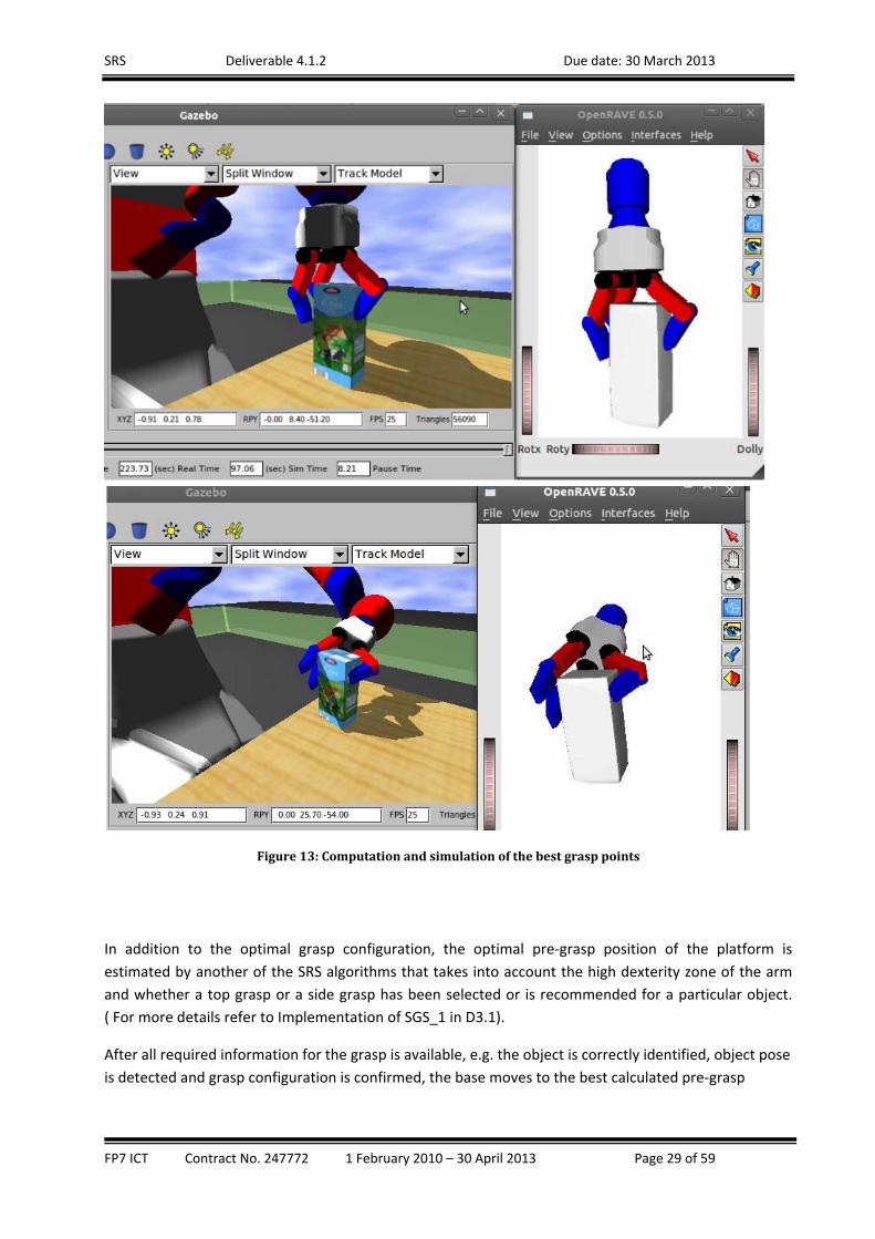
In the following figure, two different (TOP and SIDE) simulated grasp configurations are shown to the
user to allow him/her to decide which configuration to be executed for the grasp. The grasp action is
then simulated to allow the user to visualise to himself the grasp sequence. Once the user has finished
with the configuration of the grasp points for this particular object and is satisfied with the overall grasp
configuration he/she confirms this by pressing a button on the interface. Then the grasp configuration is
stored in the object database to be for this particular object in the future.
SRS Deliverable 4.1.2 Due date: 30 March 2013
FP7 ICT Contract No. 247772 1 February 2010 – 30 April 2013 Page 29 of 59
Figure13:Computationandsimulationofthebestgrasppoints
In addition to the optimal grasp configuration, the optimal pre‐grasp position of the platform is
estimated by another of the SRS algorithms that takes into account the high dexterity zone of the arm
and whether a top grasp or a side grasp has been selected or is recommended for a particular object.
( For more details refer to Implementation of SGS_1 in D3.1).
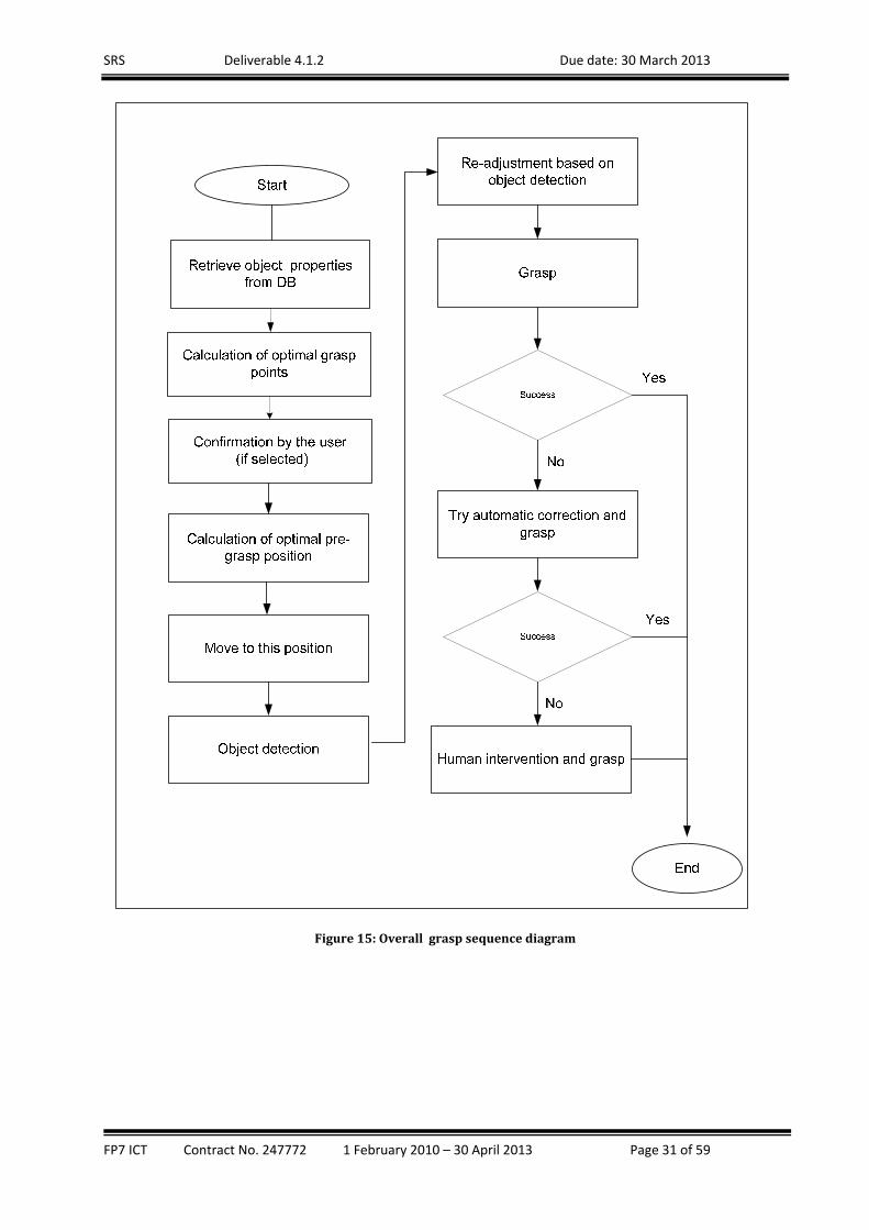
After all required information for the grasp is available, e.g. the object is correctly identified, object pose
is detected and grasp configuration is confirmed, the base moves to the best calculated pre‐grasp

SRS Deliverable 4.1.2 Due date: 30 March 2013
FP7 ICT Contract No. 247772 1 February 2010 – 30 April 2013 Page 30 of 59
position and a grasp sequence is executed on the robot. The actual grasp involves movements of the
arm and the hand in an action sequence which is shown in the following figure:
Figure14:Graspactionsequencestatemachine Due to inaccuracies in the positioning of the base and/or in coordinates of the detected object, it is
possible that on certain occasions the grasp action fails to get hold firmly of the object. As a result, the
object may slip from the robot’s fingers so it cannot be grasped properly. This condition is detected by
the tactile pressure sensors embeded in fingers of the gripper. The Decision Making module, upon
discovery of such conditions blocks the execution of the arm movement to the tray. Instead the DM
controls the robot, i.e. the possition of the base, to reattempt grasping from different possition. If these
fail as well the involvement of a human remote operator is sought. The overal procedure for detection,
grasp and user intervention in case of errors is shown on the following figure.
SRS Deliverable 4.1.2 Due date: 30 March 2013
FP7 ICT Contract No. 247772 1 February 2010 – 30 April 2013 Page 31 of 59
Figure15:Overallgraspsequencediagram

SRS Deliverable 4.1.2 Due date: 30 March 2013
FP7 ICT Contract No. 247772 1 February 2010 – 30 April 2013 Page 32 of 59
Operatorprofiles
A mechanism for storing user profile data in the KB and a log on mechanism on UI (both UI_PRI and
UI_PRO) have been implemented. The users have to be authenticated through a log‐on procedure
before they are authorised to get remote access to the SRS system.
Each operator has a profile, stored in the SRS database, which specifies the privilege level, i.e. what
actions this operator can execute on the robot. For example, the son of the elderly person might have a
full privilege to control COB while the children in the family may be only allowed to communicate over
the UI_PRI with the elderly person to reduce the risk of wrong or irresponsible actions.
Additionally, knowing who is operating the robot at any time will enable logging of the remote
operator actions and “learning” from them. Eventually, as described in the “Self‐learning” section
below, this will allow the robot control algorithms to adapt to the individual style of each registered
remote operator and to offer specific help depending on the level of expertise of the individual
operator. For example, if the logged‐in operator, according to the recent log, has not been very
successful in controlling the platform to execute a specific action as soon as this action is selected a call
to the professional service will be offered.
Self‐learning
The learning in SRS relies on historic data from the operation of the SRS robot and on the
knowledgebase to produce rules that are taken into account by the DM when planning the actions of
the SRS robot. In practice, the emphasis of the work in this task has been on the expansion of Self‐
learning services, i.e. SLS_1, SLS_2,that have been developed in WP3, to achieve reasoning mechanism
adjustment and world model.
The self‐learning service SLS_1 is able to develop mappings from action patterns to semantic relations,
APSR, to add new semantic relations to a world model. The mappings are generated based on the
correlation of actions and semantic relations, given data of actions that n remote operator (RO) has
taken, a target object X, and a list of other objects that are related to the action such as table_1 in
move(base, table_1, near) and fridge_1 in open(door, fridge_1). Actions that have high correlation
values with hypothesizes such as in(X, fridge_1) or on(X, table_1) are retained and “encapsulated” to
form an AP, while the corresponding hypothesis is considered as an SR. So a mapping APSR will be
established. In Task 4.2, more complicated cases where two or more ROs, controlling the system, will be
considered. In the situations where more ROs who have different habits are involved, the APs learnt
based on the simple correlation can lead to wrong SR. For example for the following two mappings:
“move(base, table_1, near) and grasp(X) ‐> on(X, table_1)”,
“open(door, fridge_1) and grasp(X) and close(door, fridge_1) ‐> in(X,fridge_1)”
SRS Deliverable 4.1.2 Due date: 30 March 2013
FP7 ICT Contract No. 247772 1 February 2010 – 30 April 2013 Page 33 of 59
If RO1 has the habit of open(door, fridge_1), grasp(X) and close(door, fridge_1), while RO2 has his habit
open(door, fridge_1), grasp(X), put(X, table_1), close(door, fridge_1), move(base, table_1, near),
grasp(X). In the second case, the SR of on(X, table_1) can be derived because of the appearance of
move(base, table_1, near) and grasp(X), despite the fact that X was in fridge_1 in the second case.
The operator profile, described earlier in this section, will be used to “separate” action sequence data
according to ROs. One RO will have his own “individualized” data set. At the learning stage, RO will be
first identified and the corresponding dataset will be used to establish individualized mappings, as
depicted in the following figure. At a later stage the mappings are to be used for the corresponding ROs
only.
Figure16:Learningfromactionsequenceoftheremoteoperators,SLS1
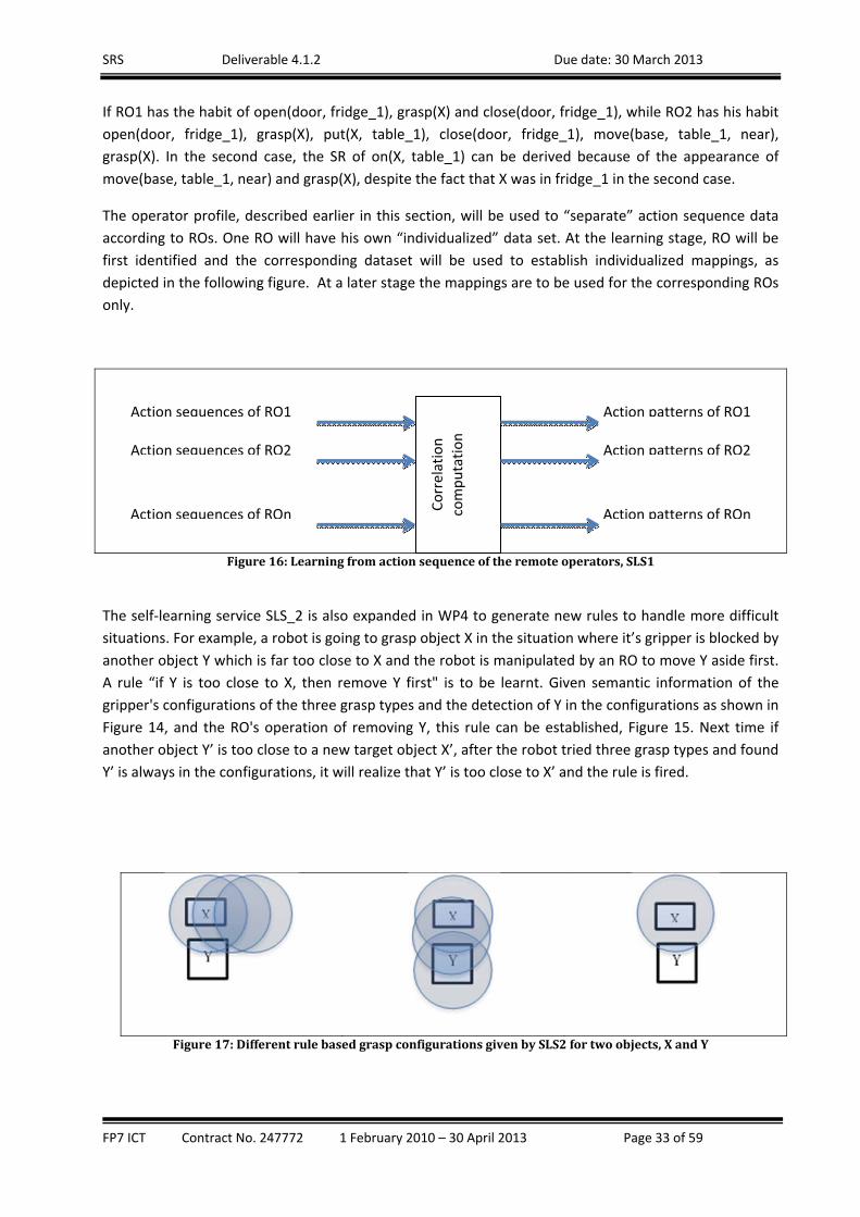
The self‐learning service SLS_2 is also expanded in WP4 to generate new rules to handle more difficult
situations. For example, a robot is going to grasp object X in the situation where it’s gripper is blocked by
another object Y which is far too close to X and the robot is manipulated by an RO to move Y aside first.
A rule “if Y is too close to X, then remove Y first" is to be learnt. Given semantic information of the
gripper's configurations of the three grasp types and the detection of Y in the configurations as shown in
Figure 14, and the RO's operation of removing Y, this rule can be established, Figure 15. Next time if
another object Y’ is too close to a new target object X’, after the robot tried three grasp types and found
Y’ is always in the configurations, it will realize that Y’ is too close to X’ and the rule is fired.
Figure17:DifferentrulebasedgraspconfigurationsgivenbySLS2fortwoobjects,XandY
Correlation
computation
Action sequences of RO1
Action sequences of RO2
Action sequences of ROn
Action patterns of RO1
Action patterns of RO2
Action patterns of ROn
SRS Deliverable 4.1.2 Due date: 30 March 2013
FP7 ICT Contract No. 247772 1 February 2010 – 30 April 2013 Page 34 of 59
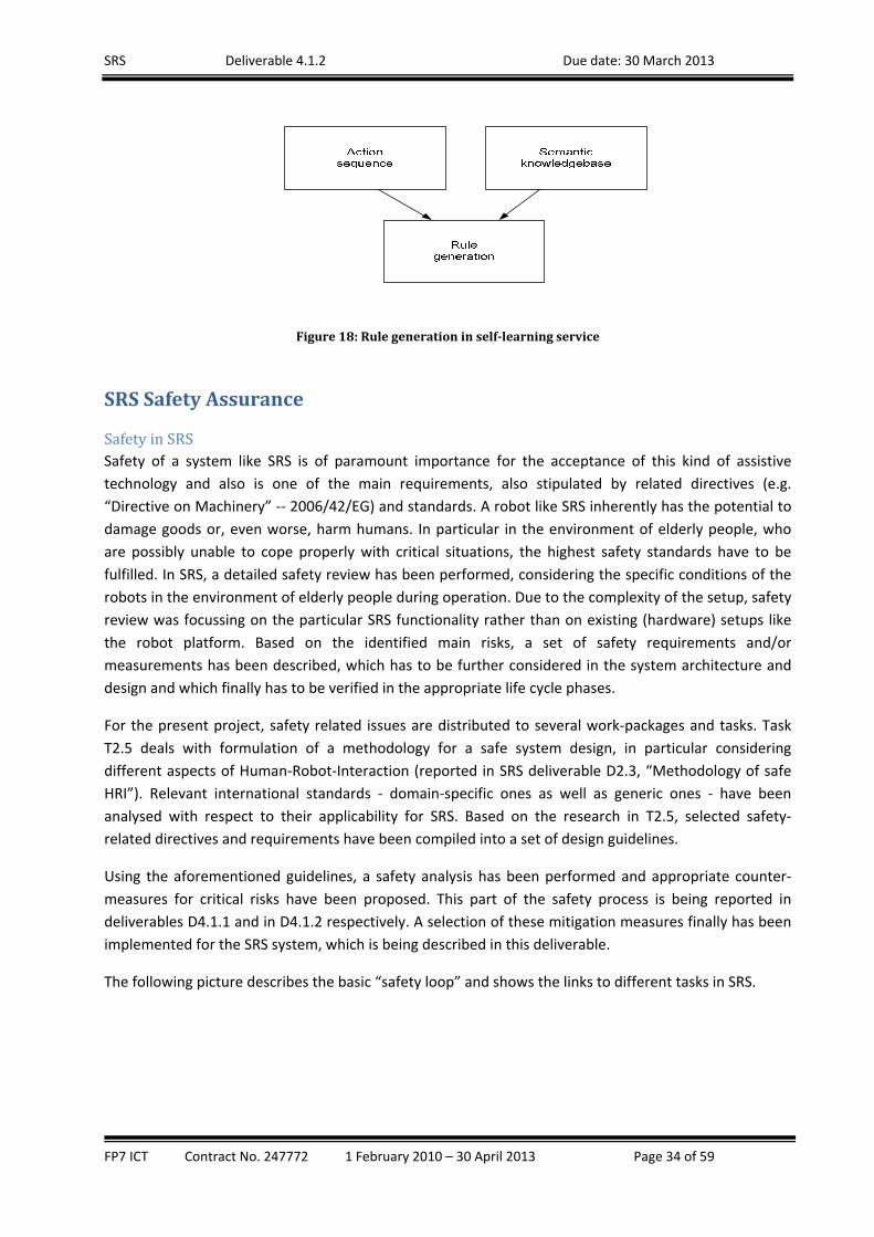
Figure18:Rulegenerationinself‐learningservice
SRSSafetyAssurance
SafetyinSRSSafety of a system like SRS is of paramount importance for the acceptance of this kind of assistive
technology and also is one of the main requirements, also stipulated by related directives (e.g.
“Directive on Machinery” ‐‐ 2006/42/EG) and standards. A robot like SRS inherently has the potential to
damage goods or, even worse, harm humans. In particular in the environment of elderly people, who
are possibly unable to cope properly with critical situations, the highest safety standards have to be
fulfilled. In SRS, a detailed safety review has been performed, considering the specific conditions of the
robots in the environment of elderly people during operation. Due to the complexity of the setup, safety
review was focussing on the particular SRS functionality rather than on existing (hardware) setups like
the robot platform. Based on the identified main risks, a set of safety requirements and/or
measurements has been described, which has to be further considered in the system architecture and
design and which finally has to be verified in the appropriate life cycle phases.
For the present project, safety related issues are distributed to several work‐packages and tasks. Task
T2.5 deals with formulation of a methodology for a safe system design, in particular considering
different aspects of Human‐Robot‐Interaction (reported in SRS deliverable D2.3, “Methodology of safe
HRI”). Relevant international standards ‐ domain‐specific ones as well as generic ones ‐ have been
analysed with respect to their applicability for SRS. Based on the research in T2.5, selected safety‐
related directives and requirements have been compiled into a set of design guidelines.
Using the aforementioned guidelines, a safety analysis has been performed and appropriate counter‐
measures for critical risks have been proposed. This part of the safety process is being reported in
deliverables D4.1.1 and in D4.1.2 respectively. A selection of these mitigation measures finally has been
implemented for the SRS system, which is being described in this deliverable.
The following picture describes the basic “safety loop” and shows the links to different tasks in SRS.

SRS Deliverable 4.1.2 Due date: 30 March 2013
FP7 ICT Contract No. 247772 1 February 2010 – 30 April 2013 Page 35 of 59
Figure19:“SAFETY”INSRSPROJECT(figure adapted from the deliverable D2.3)
SRSSafetyAnalysisBased on the methodology outlined in deliverable D2.3 a safety analysis has been performed. Analysis
has been performed in a matrix structure with system (sub‐)functions and components in one axis and
possible hazards in the other axis. Hazards have been grouped into
Mechanical hazards
Electrical hazards
Hazards from Operational Environment
Hazards from User Interaction, Ergonomics
Hazards from Emissions, and
Hazards from Malfunction of Control System
Different combinations of functionality and hazard could be identified and described in more detail. The
following figure 19 shows a part of the risk management matrix – selected risks are being outlined in the
following.
T2.5: SRS Safety Approaches
Safety Analysis Safety Measures
Standards(D1.2)
RequirementsScenarios(D1.1)
Safety Requirements
Risk Analysis
SRS PrototypeT5.3
Guidelines/Methodology(D2.3)
T4.3
User Interface(T2.4, T2.7)
Standards
Requirements(D2.2)
Final Report(D1.4, D4.1)
UI ImplementationT5.1
Usability EvaluationT2.6
Design Principles(D2.2)

SRS Deliverable 4.1.2 Due date: 30 March 2013
FP7 ICT Contract No. 247772 1 February 2010 – 30 April 2013 Page 36 of 59
Figure20:Riskmanagementmatrix(example)
Identified risks (example):
1.) Error in planning results in bad trajectory (e.g. driving over step, stairs) robot can tilt/turn
over
2.) Tilting over due to movement based on erroneous trajectory or sudden appearance of obstacle.
3.) cf 2.)
4.) cf 2.)
5.) Robot tilts due to not detected obstacle (e.g. step), or detection result wrong
6.) Bad trajectory due to wrongly self‐location cf 1.)
7.) Wrong input can lead to bad trajectory cf 6.)
8.) Wrong map data can lead to bad trajectory planning cf 1.)
9.) cf. 8.)
10.) Error in planning results in bad trajectory (e.g. collision between arm and environment) robot
can tilt/turn over due to external force
In the next step of the risk analysis, a FMEA has been performed with selected risks from the
aforementioned Risk management matrix (see figure 20).

SRS Deliverable 4.1.2 Due date: 30 March 2013
FP7 ICT Contract No. 247772 1 February 2010 – 30 April 2013 Page 37 of 59
Figure21:FMEAforselectedrisks(example)
In the final phase of risk management, some risks have been selected and mitigation measures have
been proposed (and partly implemented). Such mitigation measures are basically dealing with the
software “environment” of the robot rather than with the robot as such. For the basic functions of the
robot itself, a throughout analysis of safety issues and corresponding mitigation measures, i.e.
redundant sensor systems for the manipulator and the mobile platform, hardware speed limitation,
safety issued for exceeding of payload, hardware based monitor for unintended movement, etc, is being
recommended for the next release of the CoB system. In the framework of the present SRS project, the
following mitigation measures have been investigated in more detail:
1. Safety system including power sensing and communication watchdog and wireless (emergency)
stop
2. Detection of the presence and the location of local user(s) in the working area of the robot
system
3. Safety related elements regarding change of operation modes and transfer of control
4. Collision avoidance for the manipulator arm
5. Safety related improvements of the foldable tray
SafetySystemThe inclusion of a dedicated hardware based safety system is proposed. There are five main functions of
such a system:
1. Power sensing
2. Encoder plausibility check
3. Standstill monitoring
4. Wireless (emergency) stop
5. Communication watchdog

SRS Deliverable 4.1.2 Due date: 30 March 2013
FP7 ICT Contract No. 247772 1 February 2010 – 30 April 2013 Page 38 of 59
The proposed safety system, realised as a safety board, should be integrated into the COB safety circuit.
If one of the functions shows an error state, the safety circuit will be interrupted automatically and the
robot comes to an immediate stop (plus any other function foreseen for COB in emergency stop
situation). The “power sensing” module of the safety board ensures a correct power supply of safety
relevant system parts (e.g. sensors for obstacle avoidance) because sensor readings might be unreliable
in case of under‐supply. The “encoder plausibility check” aims to observe correct cabling of safety
relevant encoders (in our case encoders of the mobile platform). By permanent comparison of the signal
and the inverted signal – provided by the sensors – a (partly) broken cable can be detected very reliably.
The “standstill monitoring” should set an emergency stop if the robot system is moving without having
any move command issued (which means that the movement is undesired). For this monitor, a
hardware based counter of encoder signals is connected to a (hardware) signal defining the stop‐state. If
there is a mismatch the safety board is issuing an emergency stop. The “wireless emergency stop” is
connected to the safety board by means of a simple communication protocol. A dedicated software
watchdog is permanently checking for a valid communication – and is on his part being checked by a
hardware watchdog implemented on the safety board. If there is a communication problem, the safety
board immediately is issuing an emergency stop by interrupting the COB safety circuit. Similar behaviour
is for the “communication watchdog” between UI_LOC and safety board. The basic design of the
proposed safety board can be seen in the figure below.
Figure22:Basicdesignoftheproposed“SafetyBoard”
From operational viewpoint the most important feature of the safety system mentioned above is the
“wireless emergency stop” – this feature thus is being discussed in more detail in the following.
It is evident that such a safety measure forms an indispensable component of any safety system for a
service robot like SRS (and thus also is being requested by the upcoming safety standard). Also the robot
platform used in SRS is being equipped with such a safety component. But the main question certainly
SRS Deliverable 4.1.2 Due date: 30 March 2013
FP7 ICT Contract No. 247772 1 February 2010 – 30 April 2013 Page 39 of 59
must be: how can it be assured that such a wireless emergency stop is AVAILABLE for the user when it is
needed? There are several options which need to be discussed, like requesting the user to have the
emergency stop in reachable position all the time (e.g. wearing such a device all the time by using a belt,
or the like), distributing many emergency stop devices so that there will be always one in reach,
mounting the emergency stop to certain positions in the room, etc. Another, probably better, solution is
to “enforce” the permanent access to the emergency stop device by coupling the emergency stop
functionality with confirmation functionality. In such a setup, any robot movement would be subject to
a confirmation – in case of any unintended behaviour of the robot the user releases the confirmation
button (and maybe also activates the emergency stop button) and the robot comes to an immediate
and safe stop. Even if such a use of a (permanent or intermitting) confirmation button finally increases
system safety significantly, it also on the other hand compromises system usability (and thus maybe also
system acceptance).
For the current SRS setup, the UI_LOC will be used for such a safety measure. The assumption behind
this decision is that the UI_LOC is the primary input device – any robot movement finally has been
initiated by means of this system component. As a consequence it can be assumed that the UI_LOC
device is in direct reach for the user most of the time. It needs to be clarified that such a emergency
stop functionality implemented in a wireless communication device like the UI_LOC is NOT fulfilling all
requirements of a certified emergency stop device. Nevertheless, the chosen implementation ensures a
high reliability of the desired “stop”‐functionality; legal aspects finally may have to be clarified with
responsible institutions (like notified bodies, etc) before commercialization.
The implementation of the stop‐function is based on a configurable 3‐bit pattern constantly sent from
the safety board of the robot to UI_LOC. After receipt of the pattern, a corresponding pattern is being
sent back to the safety board where a particular decoder is generating a trigger to restart a watchdog‐
timer (WDT). If no pattern is being received ‐ e.g. because UI_LOC is out of reach, sending no signal due
to loss of power, sending no signal due to communication problem, or because of activated stop‐button
by the user – the WDT is issuing a stop signal to the safety circuit which finally immediately brings the
robot to a safe stop.
ChangeofoperationmodesandtransferofcontrolBoth the “Essential Requirements” (refer to deliverable D2.3) as well as risk analysis requires certain
measures for a safe implementation of different operating modes. For SRS system the main operation
mode is the “automatic mode”. First instance in case of exceptional cases is the local user interface
UI_LOC. From here, transfer of command to remote interfaces (UI_PRI or UI_PRO) must be initiated by
the local user. In addition, there is a need for a clear process for the transfer of command from UI_PRI to
UI_PRO and vice versa (work in progress). For selected scenarios (e.g. emeregency situation) there must
be the exception that a remote interface is initiating a robot service.
Another desire resulting from the “Essential Requirements” is to permanently inform the user(s) about
the active operation mode. In SRS the UI_LOC permanently shows whether the robot is being in idle
mode, automatic mode, or remote controlled mode. In addition, and movement issued by one of the
remote interfaces is being signalised (in advance) by visual and acoustic warnings.
The following figures show some UI_LOC screenshots for the aforementioned safety features.

SRS Deliverable 4.1.2 Due date: 30 March 2013
FP7 ICT Contract No. 247772 1 February 2010 – 30 April 2013 Page 40 of 59
Figure23:SafetyfunctionsUI_LOC–Screenshots.The local user will be asked if the SRS can be switched into remote control (left image); UI_LOC clearly shows that the robot is
in remote operation mode and also shows next process step (right image)
HumanSensingAs the SRS system serves the needs of the elderly user, interacting with the person is occurring
frequently. In such cases there is a strong need of up‐to‐date information about the location and the
state of the person, e.g. moving or standing still. Therefore, the goal of the human sensing subtask is to
detect the presence and the location of a human in the vicinity of the robot and to make this
information available to the other modules in the SRS system. In contrast, in other circumstances, the
currently executed task by the SRS system can only be performed in a safe and unobtrusive way when
the robot is as away from the local user as possible. Such tasks mainly involve arm manipulation, which
is considered not safe to be carried out when there is a human in close proximity, or movement of the
platform. The algorithms that are controlling the movement of the robotic system need to be constantly
updated with information about the location and the predicted movement of the local user so they can
plan the robot actions accordingly in the safest and the most efficient way.
In addition to the automatic control, at times, the SRS robot would be remotely controlled by a remote
operator (RO). The remote control can be either high level, as in the case of UI_PRI where extended
family members select from a list of pre‐defined high level tasks, or low level, as in the case of UI_PRO
where a professional RO controls manually the platform and the arm. In both cases the remote
operator has to be aware of the presence and location of the local user. The video feed from the
cameras alone is not sufficient for maintaining adequate level of awareness of the RO about the local
environment and the presence of a human because of its narrow field of view and the constant
movements of the robot when carrying out tasks. Therefore, it is considered necessary that the remote
operator should be informed of the location of the local user by additional means, i.e. a marker on the
room map showing the position of human relative to the robot and other items of furniture. The room
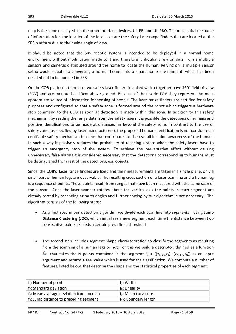
SRS Deliverable 4.1.2 Due date: 30 March 2013
FP7 ICT Contract No. 247772 1 February 2010 – 30 April 2013 Page 41 of 59
map is the same displayed on the other interface devices, UI_PRI and UI_PRO. The most suitable source
of information for the location of the local user are the safety laser range finders that are located at the
SRS platform due to their wide angle of view.
It should be noted that the SRS robotic system is intended to be deployed in a normal home
environment without modification made to it and therefore it shouldn’t rely on data from a multiple
sensors and cameras distributed around the home to locate the human. Relying on a multiple sensor
setup would equate to converting a normal home into a smart home environment, which has been
decided not to be pursued in SRS.
On the COB platform, there are two safety laser finders installed which together have 360° field‐of‐view
(FOV) and are mounted at 10cm above ground. Because of their wide FOV they represent the most
appropriate source of information for sensing of people. The laser range finders are certified for safety
purposes and configured so that a safety zone is formed around the robot which triggers a hardware
stop command to the COB as soon as detection is made within this zone. In addition to this safety
mechanism, by reading the range data from the safety lasers it is possible the detections of humans and
positive identifications to be made at distances far beyond the safety zone. In contrast to the use of
safety zone (as specified by laser manufacturers), the proposed human identification is not considered a
certifiable safety mechanism but one that contributes to the overall location awareness of the human.
In such a way it passively reduces the probability of reaching a state when the safety lasers have to
trigger an emergency stop of the system. To achieve the preventative effect without causing
unnecessary false alarms it is considered necessary that the detections corresponding to humans must
be distinguished from rest of the detections, e.g. objects.
Since the COB’s laser range finders are fixed and their measurements are taken in a single plane, only a
small part of human legs are observable. The resulting cross section of a laser scan line and a human leg
is a sequence of points. These points result from ranges that have been measured with the same scan of
the sensor. Since the laser scanner rotates about the vertical axis the points in each segment are
already sorted by ascending azimuth angles and further sorting by our algorithm is not necessary. The
algorithm consists of the following steps:
As a first step in our detection algorithm we divide each scan line into segments using Jump
Distance Clustering (JDC), which initializes a new segment each time the distance between two
consecutive points exceeds a certain predefined threshold.
The second step includes segment shape characterization to classify the segments as resulting
from the scanning of a human legs or not. For this we build a descriptor, defined as a function
that takes the N points contained in the segment Sj = {(x1,y1,z1)…(xN,yN,zN)} as an input
argument and returns a real value which is used for the classification. We compute a number of
features, listed below, that describe the shape and the statistical properties of each segment:
f1: Number of points f7: Width
f2: Standard deviation f8: Linearity
f3: Mean average deviation from median f9: Mean curvature
f4: Jump distance to preceding segment f10: Boundary length

SRS Deliverable 4.1.2 Due date: 30 March 2013
FP7 ICT Contract No. 247772 1 February 2010 – 30 April 2013 Page 42 of 59
f5: Jump distance to succeeding segment f11: Boundary regularity
f6: Circularity f12: Mean angular difference Table3:Geometricfeaturesusedindetectionofhumanlegs
In the third step we use a random forest classifier to perform binary classification on the current
set of clusters. The classifier is trained in advance using positive, negative and
test data sets. Once a segment is classified as a measurement of a human leg it is stored in the
memory. Later the distance between the stored leg candidates is assessed and if it is below a
certain threshold the candidates are grouped as a pair of legs.
Finally, the algorithm uses the coordinates of the pairs of legs to update a particle filter for
tracking of the detected human. The current estimated position of the human is published to a
ROS topic to be used by other modules that need this information.
The detection of a human in the scene by the algorithm is visualised in the following figure.
Figure24:Humandetectionfromlaserrangedata.Note: The red ellipse denotes detection of a human.
Additional details of the developed algorithm can be found in (Noyvirt,2012), which is published as a
direct result of the work carried out in T4.3 in WP4.

SRS Deliverable 4.1.2 Due date: 30 March 2013
FP7 ICT Contract No. 247772 1 February 2010 – 30 April 2013 Page 43 of 59
The Decision Making (DM), the UI_PRI and UI_PRO modules use the information published by the
Human Sensing (HS) module either by subscribing to the relevant ROS topics or by receiving ActionLib7
calls from the Human Sensing as shown in the diagram below.
Figure25:InformationexchangemechanismbetweentheHSandtherestofthemodules Experiments aimed at establishing the accuracy of the algorithm were carried out with the COB
hardware platform. At this experiment people walking around the robot were successfully detected at
all times. Subsequent improvements were undertaken in the algorithm aimed at reducing the false
positive detection rate, i.e. clutter.
When a human is detected in close proximity around the robot the DM is notified to take an appropriate
action. Based on the context of currently executed action, the DM takes appropriate actions to reduce
the risk to the human. For example, as described in the following section, the robot always tries to
orient its “service side” when dealing with human or if an arm manipulation action is underway then
the movements are restricted until the arm is brought into a stable state.
HumantrackanalysisA novel MCMC based algorithm has been developed to form a part of Human Presence Sensor Unit
(HPSU) in task T4.3 which allows reconstruction and analysis of multiple human tracks from the
detections made by the robot. The algorithm uses sensor data, as described in the section Human
7 http://ros.org/wiki/actionlib
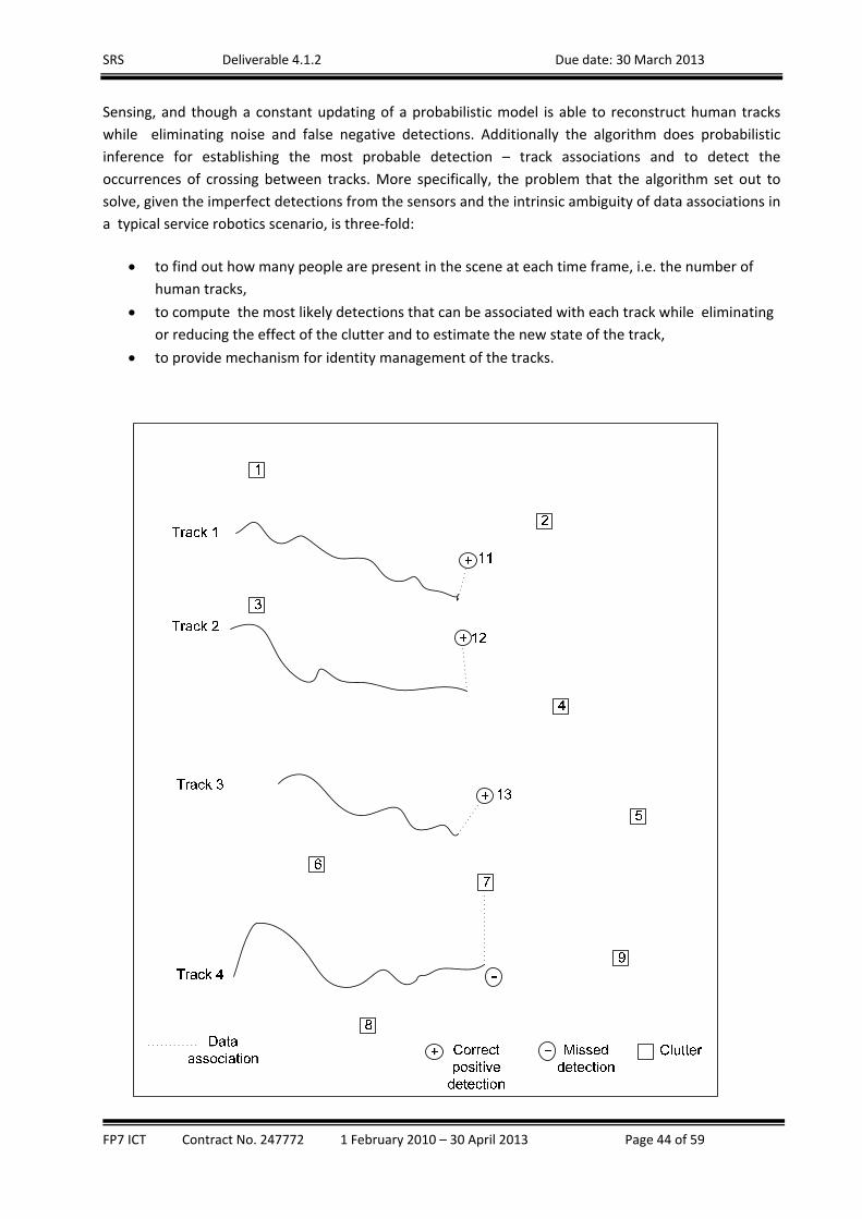
SRS Deliverable 4.1.2 Due date: 30 March 2013
FP7 ICT Contract No. 247772 1 February 2010 – 30 April 2013 Page 44 of 59
Sensing, and though a constant updating of a probabilistic model is able to reconstruct human tracks
while eliminating noise and false negative detections. Additionally the algorithm does probabilistic
inference for establishing the most probable detection – track associations and to detect the
occurrences of crossing between tracks. More specifically, the problem that the algorithm set out to
solve, given the imperfect detections from the sensors and the intrinsic ambiguity of data associations in
a typical service robotics scenario, is three‐fold:
to find out how many people are present in the scene at each time frame, i.e. the number of
human tracks,
to compute the most likely detections that can be associated with each track while eliminating
or reducing the effect of the clutter and to estimate the new state of the track,
to provide mechanism for identity management of the tracks.
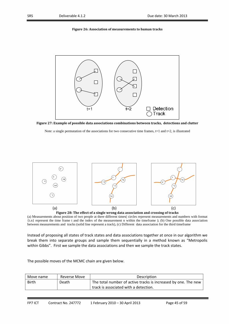
SRS Deliverable 4.1.2 Due date: 30 March 2013
FP7 ICT Contract No. 247772 1 February 2010 – 30 April 2013 Page 45 of 59
Figure26:Associationofmeasurementstohumantracks
Figure27:Exampleofpossibledataassociationscombinationsbetweentracks,detectionsandclutter
Note: a single permutation of the associations for two consecutive time frames, t=1 and t=2, is illustrated
(a) (b) (c) Figure28:Theeffectofasinglewrongdataassociationandcrossingoftracks
(a) Measurements about position of two people at three different times( circles represent measurements and numbers with format {t.n} represent the time frame t and the index of the measurement n within the timeframe ); (b) One possible data association between measurements and tracks (solid line represent a track), (c) Different data association for the third timeframe
Instead of proposing all states of track states and data associations together at once in our algorithm we break them into separate groups and sample them sequentially in a method known as “Metropolis within Gibbs”. First we sample the data associations and then we sample the track states. The possible moves of the MCMC chain are given below.
Move name Reverse Move Description
Birth Death The total number of active tracks is increased by one. The new track is associated with a detection.

SRS Deliverable 4.1.2 Due date: 30 March 2013
FP7 ICT Contract No. 247772 1 February 2010 – 30 April 2013 Page 46 of 59
Death Birth The total number of tracks is decreased by one. The
associations of the track after time (if any) are assigned to clutter.
Decrease detection delay window
Increase detection delay window
Detections are assigned earlier to tracks
Increase detection delay window
Decrease detection delay window
This move causes detections to assigned later to tracks by increase of the detection delay window. When the window is bigger the chance for confusion with clutter is smaller.
Use a delay window
Do not use a delay window
This move switches on and off the use of a delay window.
Table4:PossiblemovesintheMCMCchain
A high level overview of the developed algorithm is presented below. First, a track is randomly
selected from all currently active tracks. Then the algorithm proceeds by sampling an MCMC move
from all possible moves given in the Error! Reference source not found.4 . Next, it samples data
associations and in the final step the state of the selected track is sampled. Within the step that
samples the of states a Kalman filter is used to make a prediction of the track state based on the data
associations hypothesis made in the previous step, i.e. sampling the data associations. Finally the
algorithm calculates the acceptance ratio using the proposal probabilities.
Input: Observations : , time period Output: Estimated track states : and data associations
1: for = 1 to do 2: for 2 _ do 3: choose a track ∊ 1, . . , } randomly 4: choose a _ ∊ 1, . . ,4} randomly 5: chose proposal origin time frame ∗ depending on the _ 6: copy a particle randomly from frame ∗ and track 7: create a new proposed particle ṗ from 8: propose new associations for ṗ and calculate proposal probability for them, 9: propose new state for ṗ and calculate the proposal probability for it, , | 10: calculate the posterior for ṗ 11: calculate the acceptance ratio 12: pick , uniformly distributed random number between 0 and 1, 13: if then 14: accept ṗ for the new particle 15: else 16: accept for the new particle 17: end if 18: end for 19:end for
Algorithm1:MCMC‐PFMultiHumanTracking
The results of the algorithm are graphically presented in the figure below where a unknown to the robot
track, shown with different colour crossed line, is reconstructed from detections and clutter.
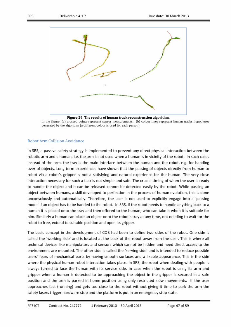
SRS Deliverable 4.1.2 Due date: 30 March 2013
FP7 ICT Contract No. 247772 1 February 2010 – 30 April 2013 Page 47 of 59
Figure29:Theresultsofhumantrackreconstructionalgorithm.
In the figure: (a) crossed points represent sensor measurements; (b) colour lines represent human tracks hypotheses generated by the algorithm (a different colour is used for each person)
RobotArmCollisionAvoidance
In SRS, a passive safety strategy is implemented to prevent any direct physical interaction between the
robotic arm and a human, i.e. the arm is not used when a human is in vicinity of the robot. In such cases
instead of the arm, the tray is the main interface between the human and the robot, e.g. for handing
over of objects. Long term experiences have shown that the passing of objects directly from human to
robot via a robot’s gripper is not a satisfying and natural experience for the human. The very close
interaction necessary for such a task is not simple and safe. The crucial timing of when the user is ready
to handle the object and it can be released cannot be detected easily by the robot. While passing an
object between humans, a skill developed to perfection in the process of human evolution, this is done
unconsciously and automatically. Therefore, the user is not used to explicitly engage into a ‘passing
mode’ if an object has to be handed to the robot. In SRS, if the robot needs to handle anything back to a
human it is placed onto the tray and then offered to the human, who can take it when it is suitable for
him. Similarly a human can place an object onto the robot’s tray at any time, not needing to wait for the
robot to free, extend to suitable position and open its gripper.
The basic concept in the development of COB had been to define two sides of the robot. One side is
called the ‘working side’ and is located at the back of the robot away from the user. This is where all
technical devices like manipulators and sensors which cannot be hidden and need direct access to the
environment are mounted. The other side is called the ‘serving side’ and is intended to reduce possible
users’ fears of mechanical parts by having smooth surfaces and a likable appearance. This is the side
where the physical human‐robot interaction takes place. In SRS, the robot when dealing with people is
always turned to face the human with its service side. In case when the robot is using its arm and
gripper when a human is detected to be approaching the object in the gripper is secured in a safe
position and the arm is parked in home position using only restricted slow movements. If the user
approaches fast (running) and gets too close to the robot without giving it time to park the arm the
safety lasers trigger hardware stop and the platform is put in an emergency stop state.

SRS Deliverable 4.1.2 Due date: 30 March 2013
FP7 ICT Contract No. 247772 1 February 2010 – 30 April 2013 Page 48 of 59
Safetyrelatedimprovementsofthefoldabletrayandarm
From safety viewpoint, there are still some remaining risks connected with the implementation of the foldable tray. Movement of the mobile platform should be blocked until the tray is completely folded (this safety feature should be implemented in hardware) – for folding/unfolding appropriate sensing or (at least) limitation of motor current should ensure safe operation. Other potential safety risks are related to objects located on the tray, including tilting over of the object (and spilling of fluid as a possible consequence), or loosing objects during transport (objects then falling to the floor as a consequence and thus becoming a new hazard). Risks also include the possible misuse of having the tray used for stand‐up support. Appropriate counter‐measures ‐‐ like adding a border to the tray, adding sensors and similar ‐‐ are out‐of‐scope for the present SRS project but should be considered for one of the next updates of the CoB robot system.
OpenInterfaceDevelopmentStrategies
In task T4.4, “Open Interface Development Strategies”, the main focus of work has been the
development of a reliable and stable communication layer structure that can supports the required real
time communication between the SRS core system and the remote user interface devices.
ControlandcommunicationThe communication layer provides transparent, low‐ latency and high‐bandwidth connection between
the user interface and the rest of the robot system. It is based on the ROSBridge stack and allows
network remote communication between the ROS (Robot Operating System) and an UI_PRI device. Its
design concept allows implementation on various device types based on different operating systems.
The transport mechanism uses a standard network communication and the widely adopted JSON format
for message encapsulation.
In the communication exchange the following data types are used:
Mapping & Navigation data type ‐ Visualises working environment map and robot footprint
position. It is implemented as part of the SRS Mixed Reality Server and Reality Publisher nodes.
Information about map updates is published via the MapUpdate node.
Robot Feedback data type ‐ Provides information in real‐time about current robot status
(power data, health & diagnostic information), status and completion of user invoked tasks and
etc. Communication from user interface to the ROS subsystem is done via the ROSBridge stack.

SRS Deliverable 4.1.2 Due date: 30 March 2013
FP7 ICT Contract No. 247772 1 February 2010 – 30 April 2013 Page 49 of 59
Robot Actions Control data type ‐ Allows the user to execute common tasks, e.g. direct robot
control, navigation aided move to a desired map position, grasping of objects and execution of
more complex actions, e.g. “Get water”. It relies on the communication layer from user
interface to the ROS subsystem via ROSBridge stack to the SRS Decision Making Stack.
Video Transport data type – It role is to visualise the robot camera feeds and boundaries of
detected and recognised objects. It is implemented as an integral part of the SRS Mixed Reality
Server.
SRSMixedrealityserverThe SRS Mixed reality server, is an important part of the SRS’s Open Interface implementation. It
provides combined information from the map server, the navigation stack, the SRS household object
database and KB in the form of an augmented reality video stream to the UI_PRI user interface. The
MRS offloads the processing from the UI, optimizes the network bandwidth usage and allows concurrent
access to the information from various sources.
1. Internal Structure of the Mixed Reality Server and relation to the other SRS components
A schematic diagram of the Mixed Reality Server together with its components is presented in the
figure below.
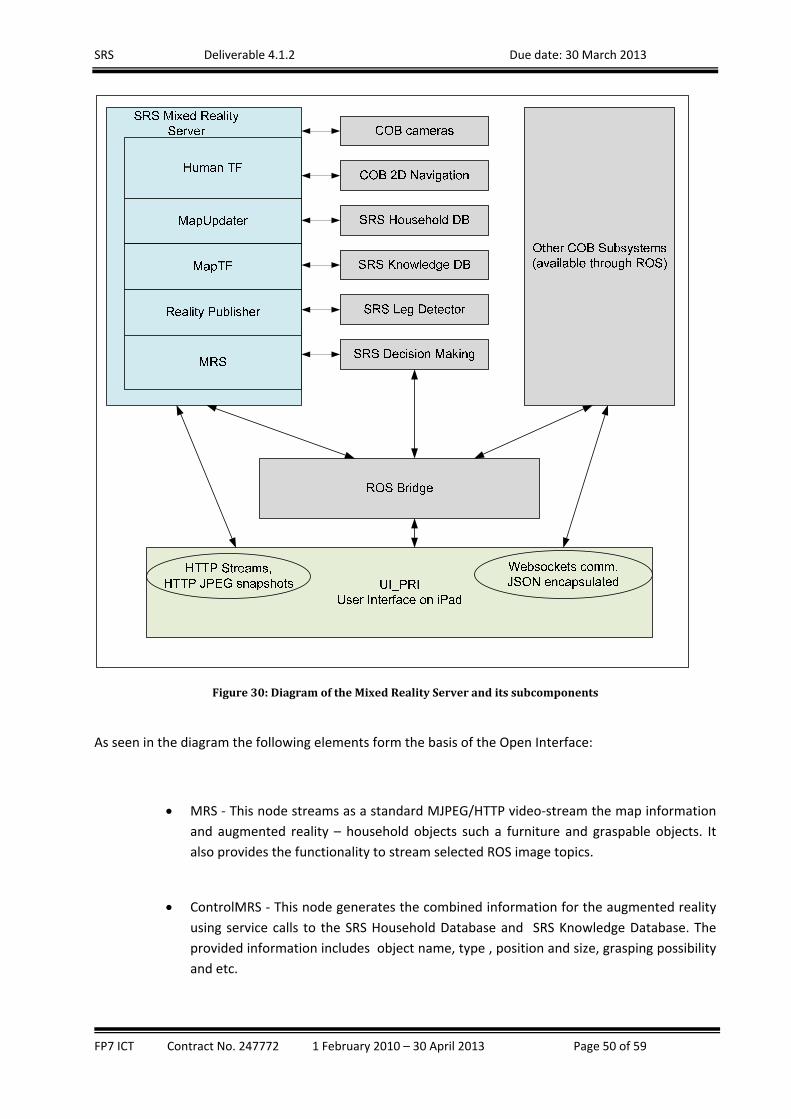
SRS Deliverable 4.1.2 Due date: 30 March 2013
FP7 ICT Contract No. 247772 1 February 2010 – 30 April 2013 Page 50 of 59
Figure30:DiagramoftheMixedRealityServeranditssubcomponents
As seen in the diagram the following elements form the basis of the Open Interface:
MRS ‐ This node streams as a standard MJPEG/HTTP video‐stream the map information
and augmented reality – household objects such a furniture and graspable objects. It
also provides the functionality to stream selected ROS image topics.
ControlMRS ‐ This node generates the combined information for the augmented reality
using service calls to the SRS Household Database and SRS Knowledge Database. The
provided information includes object name, type , position and size, grasping possibility
and etc.

SRS Deliverable 4.1.2 Due date: 30 March 2013
FP7 ICT Contract No. 247772 1 February 2010 – 30 April 2013 Page 51 of 59
RealityPublisher ‐ This node provide information to the UI about the objects located on
the augmented map.
MapTF ‐ This node converts the coordinates, and sizes from ROS metric to pixel
coordinates on virtual map and vice versa. It is provided as a ROS service to the other
SRS components including user interface.
HumanTF ‐ This node converts the Human sensing information from srs_leg_detector
and publishes the coordinates to a topic for the UI_PRI.
MapUpdate ‐ This node monitors for a map change and notifies the user interface if an
update of the map is necessary. This mechanism greatly reduces the required
bandwidth and network delay.
In the following figure the output of the MRS can be seen.
Figure31:OutputoftheMixedRealityServer
2 Communication Medium Protocols of the MRS
The following protocols have been used with the MRS
Control & Feedback protocol – TCP/IP Web‐sockets via the ROSbridge stack;
Robot command interface – TCP/IP Web‐sockets via the ROSbridge stack;

SRS Deliverable 4.1.2 Due date: 30 March 2013
FP7 ICT Contract No. 247772 1 February 2010 – 30 April 2013 Page 52 of 59
Video information – TCP/IP sockets provided by custom built by BAS Mixed Reality Server stack;
Map data – Image based feed of map information via Mixed Reality Server stack.
The MRS is also in charge of providing the Assisted Detection support service for the SRS platform. The
service allows the user/operator to assist the robot in finding an object which is impossible to be found
in autonomous mode by the robot. The assistance is in the form of moving of an rectangular region of
interest by the operator on the screen until it is positioned over the area where the object is placed.
OpeninterfacedesignconceptsThe Open Interface is built on well‐established and commonly used communication protocols and data
encapsulation methods, e.g. HTTP, JSON, JPEG. The combination of the MRS and the Rosbridge stack
provides a convenient and universal access to the COB robot system. Such a concept allows usage of the
Open Interface in various situations when an interaction with the user is required. Additionally, the
interface components can easily be adapted to and used in various robotic platforms making the
interface universal tool for the field of service robotics. The optimisation of network utilization allows a
near real‐time operation in a remote access conditions. The reduced overhead of the user interface
device CPU usage lowers the power requirements and allows extended usage of the device.
ObjectModellinginHomeEnvironments
FunctionaldescriptionThe purpose of the General Household Object Database (GHOD) package is to provide static
information, e.g. shape, about objects known to the SRS system. This information is made available to
other components in the SRS system through services. The package uses both PostgresSQL8 database
and a file system repository. The database stores relational data and allows easy access to information
through SQL queries while the file stores large data files, e.g. images. The services allow other
components in SRS to insert and retrieve objects and their associated data. The database services are
the only entry point for both database and repository, preventing concurrency issues between the
components simultaneously accessing and manipulating data. When a service is invoked it fetches data
from database and then loads information from the file repository according to data retrieved from the
database. In case when a new object and its data are inserted, the corresponding service first creates
the appropriate database information and then saves the data in the repository. In the following figure
the mechanism of storing and retrieving information is visualised.
8 http://www.postgresql.org/
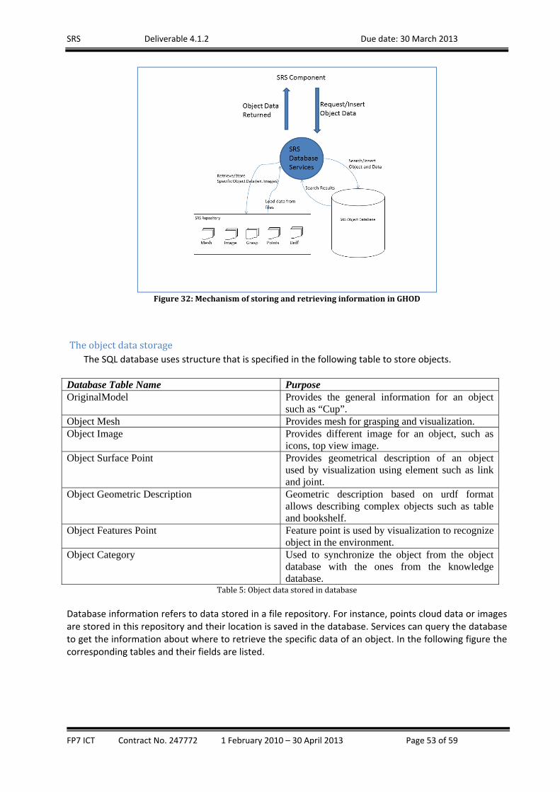
SRS Deliverable 4.1.2 Due date: 30 March 2013
FP7 ICT Contract No. 247772 1 February 2010 – 30 April 2013 Page 53 of 59
Figure32:MechanismofstoringandretrievinginformationinGHOD
TheobjectdatastorageThe SQL database uses structure that is specified in the following table to store objects.
Database Table Name Purpose OriginalModel Provides the general information for an object
such as “Cup”. Object Mesh Provides mesh for grasping and visualization. Object Image Provides different image for an object, such as
icons, top view image. Object Surface Point Provides geometrical description of an object
used by visualization using element such as link and joint.
Object Geometric Description Geometric description based on urdf format allows describing complex objects such as table and bookshelf.
Object Features Point Feature point is used by visualization to recognize object in the environment.
Object Category Used to synchronize the object from the object database with the ones from the knowledge database.
Table5:Objectdatastoredindatabase Database information refers to data stored in a file repository. For instance, points cloud data or images are stored in this repository and their location is saved in the database. Services can query the database to get the information about where to retrieve the specific data of an object. In the following figure the corresponding tables and their fields are listed.

SRS Deliverable 4.1.2 Due date: 30 March 2013
FP7 ICT Contract No. 247772 1 February 2010 – 30 April 2013 Page 54 of 59
Figure33:TablesandtheirfieldsinGHOD
Object_original_model constitutes the main table because it represent the entity object and provides a unique id for each of them and some additional information about size, name, category and a description. The table object_image is used to store data about image for a specific object; since an
object can have more than one image an additional information description is stored to represent the purpose of the image such as icon or top‐view. This information will be used as search criteria by the service which retrieves this information. The table object_category is used to store data about the category of the object; this data is used to keep aligned the object database with the knowledge database. When an object is created, the KB will be able to insert in the object database all category information required later to connect object from the knowledge base to their object database data. Category are generally stored in kbkeycategory and associated with an object using the table
object_category. Information used by visualization of objects is stored inside the feature_points table; this table holds the location of the file with the data related to the point cloud of an object. The point cloud format requires for each object some additional information such as the confidence and the descriptors, a list of sixty‐four additional points. This data is retrieved from services and it is loaded, using the point cloud library, in a ROS message. The table geometrical_description stores a link to a file urdf which describes objects in term of join and link of child elements from a root link. ROS services retrieve the data file and using the urdf parser they are able to build a marker array from link and join. Each link has a specific class, for instance a cylinder, and can be mapped on the corresponding type of visualization marker. This mapping is calculated inside the service and allows preserving the link appearance. Also the service calculate the absolute coordinate of an object used inside the marker array, starting from the relative coordinates used by urdf file referred to the root element. Grasp data is stored inside an xml file in the repository. The table grasp allows the service to retrieve grasp data for a specific object. In our case xml data, inside the file, is generated by the grasping service from the mesh of an object. This service uses the mesh to calculate the grasping and store it inside the database, to be retrieved later so that it has not calculated every time. Because mesh is stored for both visualization and grasping purpose and the format for these services is different, the table mesh can store mesh in two formats. The grasp format for visualization is a geometrical description, made of triangles and points. It is derived from a Collada file format9 and used in the visualization marker message.
9 http://en.wikipedia.org/wiki/COLLADA

SRS Deliverable 4.1.2 Due date: 30 March 2013
FP7 ICT Contract No. 247772 1 February 2010 – 30 April 2013 Page 55 of 59
TheFileRepository The repository stores object model data, e.g. the image of an object. The SQL database acts like a catalogue for those files. In fact, it contains information about the location of the specific file for each object. Also, it stores some additional information which can be queried by services. The repository is the place where most of the data is stored and each folder of repository stores specific information for the objects. Services retrieve file data location from database, then some of them return it as binary stream while others process the data inside the file to build more complex messages structure. For example, images are just loaded and sent by service serializing the data from the file in a ROS image message, while other information, such as feature points, are parsed from the file and loaded in the specific message structure of PointCloud. The following Figure shows the folder structure inside the file repository, each folder contains a specific data for the object. The folder Input is used to store data of objects that need to be inserted in database. Output folder is used for test only, to verify that the data retrieved from the service and saved in output folder is usable and identical to the original data inside the other folders.
Figure34:Thestructureofthefilerepository
4. SRSGeneralFramework‐implementationandintegrationprocess
The general framework of the SRS system is based on an open source operating system, i.e. ROS. This
message passing system allows developing modules that can be plugged plug‐in in addition to other
existing modules in ROS, e.g. navigation stack, that are available for ROS. The developed modules
comply fully with the ROS specifications and can be reused in future by the ROS community. Using ROS
has allowed the developers in SRS to eliminate the overheads associated with maintaining the
underlying communication structure and to build on the existing software.
The collaborative software development life‐cycle methodology has been adopted in the project for the
development of the SRS software. According to this methodology, the work of the technical partners
has been organized in analysis, design, implementation, testing and evaluation cycles. In particular, after
each partner has finished a cycle of internal development and successful self‐testing, they release a new
version of their source code to the common SRS source code repository for other partners to access.
Periodically, every technical partner in SRS has the duty to download the most recent versions of the

SRS Deliverable 4.1.2 Due date: 30 March 2013
FP7 ICT Contract No. 247772 1 February 2010 – 30 April 2013 Page 56 of 59
software from the repository and to test the module developed by them for compatibility with the rest
of the modules. It has proven in the SRS practice that by such frequent testing the partners were able to
identify software bugs and various communication issues between the modules. This allowed all the
problems to be addressed promptly by the appropriate partner. A number of teleconference sessions
were organized on a monthly basis monthly. The problems identified by the partners in the current
month were discussed, analysed corrective actions were planned for the next month. Since not all of
the features in the SRS code can be tested in isolation or in the simulation environment when needed
integration meetings were organized with the real COB platform at which all the modules were
integrated and tested.
Each integration meeting was planned to test the progress of the software development in SRS, e.g.
what will features will be tested, how they will tested and by whom, with separate timeslots for the
tested features. Some of the features that allowed it were tested in parallel by separate teams. At the
end of the integration meeting an action plan was created and subsequently the SRS partners worked
on this action plan.
By combining individual testing, collaborative (one‐to‐one) remote testing, teleconferences and
integration meting the SRS consortium has aimed at achieving accelerated software development with
the active involvement of the partners conducting the user studies.
5. Validation
The overall SRS system has been tested in a number of scenarios that have been identified as applicable
to elderly care at home by earlier stages of the project. From a technical perspective the scenarios
mainly include different variations of a few key elements. These elements include detection,
manipulation sequence with the arm to grasp an object, placing it on the tray and caring the object to
the person or a certain location. Further details of these scenarios can be found in Deliverable D1.3,
“SRS System Specification”.
The testing protocol of the user has been presented in Deliverable D6.1, “Testing site preparation and
protocol development”. A number of user test have been carried at the Milan “home” with elderly
users, caregivers, family members as specified in the testing protocol. In these tests the performance of
the robot was accessed and results reported in Deliverable D6.2. After the first set of user tests, i.e.
Milan test, the identified technical issues were addressed by the technical partners of the project in the
following few months. Later in the integration meetings that followed the Milan tests, the SRS system
was tested repeatedly, both as a whole and partially by modules, to confirm that the identified issues
have been addressed. Through counting of the successful and unsuccessful sequences the following
results have been achieved:
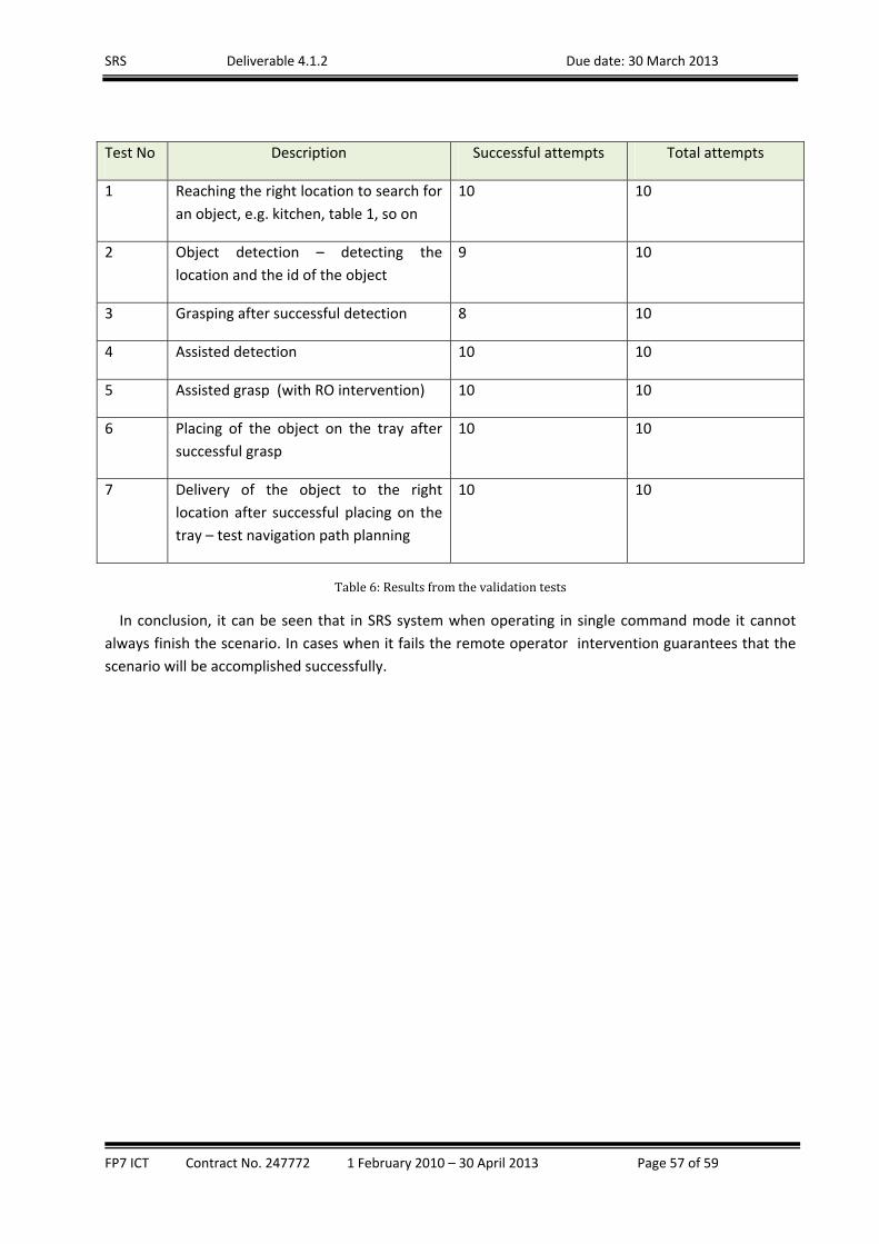
SRS Deliverable 4.1.2 Due date: 30 March 2013
FP7 ICT Contract No. 247772 1 February 2010 – 30 April 2013 Page 57 of 59
Test No Description Successful attempts Total attempts
1 Reaching the right location to search for
an object, e.g. kitchen, table 1, so on
10 10
2 Object detection – detecting the
location and the id of the object
9 10
3 Grasping after successful detection 8 10
4 Assisted detection 10 10
5 Assisted grasp (with RO intervention) 10 10
6 Placing of the object on the tray after
successful grasp
10 10
7 Delivery of the object to the right
location after successful placing on the
tray – test navigation path planning
10 10
Table6:Resultsfromthevalidationtests
In conclusion, it can be seen that in SRS system when operating in single command mode it cannot
always finish the scenario. In cases when it fails the remote operator intervention guarantees that the
scenario will be accomplished successfully.
SRS Deliverable 4.1.2 Due date: 30 March 2013
FP7 ICT Contract No. 247772 1 February 2010 – 30 April 2013 Page 58 of 59
6. References:
(Arbeiter,2012) Arbeiter, G. ; Fuchs, S.; Bormann, R.; Fischer, J.; Verl, A. Evaluation of 3D feature descriptors for classification of surface geometries in point clouds, Intelligent Robots and Systems (IROS), 2012 IEEE/RSJ International Conference on , (2012) 1644 - 1650 ISBN 9781467317375 10.1109/IROS.2012.6385552
(Calonder,2010): Calonder M., Lepetit V.,Strecha C., and Fua. P., BRIEF: Binary Robust Independent Elementary Features. In European Conference on Computer Vision, September 2010.
(Chum,2005): Chum, O., Matas, J., Matching with PROSAC-progressive sample consensus, In Computer Vision and Pattern Recognition, 2005., 220–226, CVPR 2005.
(Dempster,1977): Dempster, A., Laird, N. and Rubin, D.: Maximum Likelihood from Incomplete Data via the EM Algorithm, J. Royal Statistical Soc., vol. 39, pp. 1-38, 1977
(Hulik,2012) Hulik, R.; Beran, V.; Spanel, M.; Krsek, P.; Smrz, P. Fast and accurate plane segmentation in depth maps for indoor scenes, Intelligent Robots and Systems (IROS), 2012 IEEE/RSJ International Conference on , (2012) 1665 - 1670 ISBN 9781467317375 10.1109/IROS.2012.6385868
(Ji,2012) Ji Z, Qiu R, Noyvirt AE, Soroka AJ, Packianather MS, Setchi R, Li D, Xu S, Towards automated task planning for service robots using semantic knowledge representation, INDIN2012: IEEE 10th International Conference on Industrial Informatics , (2012) 1194-1201 ISBN 9781467303125 10.1109/INDIN.2012.6301131
(Liu,2012a) Liu B, Li D, Qiu R, Yue Y, Maple C, Gu S, Fuzzy optimisation based symbolic grounding for service robots, Intelligent Robots and Systems (IROS), 2012 IEEE/RSJ International Conference on , (2012) 1658-1664 ISBN 9781467317375 10.1109/IROS.2012.6385777
(Liu,2012b) Liu B, Li D, Yue Y, Maple C, Qiu R, Fuzzy logic based symbolic grounding for best grasp pose for homecare robotics, INDIN 2012: IEEE 10th International Conference on Industrial Informatics , (2012) 1164-1169 ISBN 9781467303118 10.1109/INDIN.2012.6300855
(Noyvirt,2012) Noyvirt AE, Qiu R, Human detection and tracking in an assistive living service robot through multimodal data fusion, INDIN 2012: IEEE 10th International Conference on Industrial Informatics , (2012) 1176-1181 ISBN 9781467303118 10.1109/INDIN.2012.6301153
(Qiu,2012a) Qiu R, Noyvirt A, Ji Z, Soroka AJ, Li D, Liu B, Arbeiter G, Weisshardt F, Xu S, Integration of symbolic task planning into operations within an unstructured environment, International Journal of Intelligent Mechatronics and Robotics, 2 (3) (2012) 38-57 ISSN 2156-1664 10.4018/ijimr.2012070104
(Qiu,2012b) Qiu R, Ji Z, Noyvirt A, Soroka AJ, Setchi R, Pham DT, Xu S, Shivarov N, Pigini L, Arbeiter G, Weisshardt F, Graf B, Mast M, Blasi L, Facal D, Rooker M, Lopez R, Li D, Liu B, Kronreif G, Smrz P, Towards robust personal assistant robots: Experience gained in the SRS project, Intelligent Robots and Systems (IROS), 2012 IEEE/RSJ International Conference on , (2012) 1651-1657 ISBN 9781467317375 10.1109/IROS.2012.6385727
(Soroka,2012) Soroka AJ, Qiu R, Noyvirt A, Ji Z, Challenges for service robots operating in non-industrial environments, Industrial Informatics (INDIN), 2012 10th IEEE International Conference on , (2012) 1152-1157 ISBN 9781467303125 10.1109/INDIN.2012.6301139
(Zhu,2008): Zhu, C., Sun, W. and Sheng, W.: Wearable sensors based human intention recognition in smart assisted living systems, In IEEE International Conference on Information and Automation, pp. 954-959, 2008
SRS Deliverable 4.1.2 Due date: 30 March 2013
FP7 ICT Contract No. 247772 1 February 2010 – 30 April 2013 Page 59 of 59
7. Appendixes
AppendixA:ResearchPublicationsfromtheSRSProject
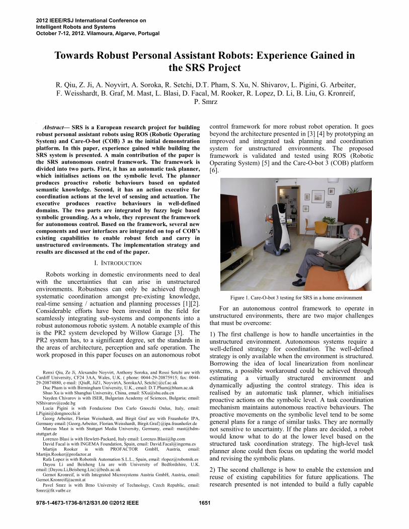
h
Abstract— SRS is a European research project for building
robust personal assistant robots using ROS (Robotic Operating
System) and Care-O-bot (COB) 3 as the initial demonstration
platform. In this paper, experience gained while building the
SRS system is presented. A main contribution of the paper is
the SRS autonomous control framework. The framework is
divided into two parts. First, it has an automatic task planner,
which initialises actions on the symbolic level. The planner
produces proactive robotic behaviours based on updated
semantic knowledge. Second, it has an action executive for
coordination actions at the level of sensing and actuation. The
executive produces reactive behaviours in well-defined
domains. The two parts are integrated by fuzzy logic based
symbolic grounding. As a whole, they represent the framework
for autonomous control. Based on the framework, several new
components and user interfaces are integrated on top of COB’s
existing capabilities to enable robust fetch and carry in
unstructured environments. The implementation strategy and
results are discussed at the end of the paper.
I. INTRODUCTION
Robots working in domestic environments need to deal with the uncertainties that can arise in unstructured environments. Robustness can only be achieved through systematic coordination amongst pre-existing knowledge, real-time sensing / actuation and planning processes [1][2]. Considerable efforts have been invested in the field for seamlessly integrating sub-systems and components into a robust autonomous robotic system. A notable example of this is the PR2 system developed by Willow Garage [3]. The PR2 system has, to a significant degree, set the standards in the areas of architecture, perception and safe operation. The work proposed in this paper focuses on an autonomous robot
Renxi Qiu, Ze Ji, Alexandre Noyvirt, Anthony Soroka, and Rossi Setchi are with
Cardiff University, CF24 3AA, Wales, U.K. ( phone: 0044-29-20875915; fax: 0044-29-20874880, e-mail: {QiuR, JiZ1, NoyvirtA, SorokaAJ, Setchi}@cf.ac.uk
Duc Pham is with Birmingham University, U.K., email: [email protected] Shuo Xu is with Shanghai University, China, email: [email protected] Nayden Chivarov is with ISER, Bulgarian Academy of Sciences, Bulgaria; email:
[email protected] Lucia Pigini is with Fondazione Don Carlo Gnocchi Onlus, Italy, email:
[email protected] Georg Arbeiter, Florian Weisshardt, and Birgit Graf are with Fraunhofer IPA,
Germany email:{Georg.Arbeiter, Florian.Weisshardt, Birgit.Graf}@ipa.fraunhofer.de Marcus Mast is with Stuttgart Media University, Germany, email: mast@hdm-
stuttgart.de Lorenzo Blasi is with Hewlett-Packard, Italy email: [email protected] David Facal is with INGEMA Foundation, Spain, email: [email protected] Martijn Rooker is with PROFACTOR GmbH, Austria, email:
[email protected] Rafa Lopez is with Robotnik Automation S.L.L., Spain, email: [email protected] Dayou Li and Beisheng Liu are with University of Bedfordshire, U.K.
email:{Dayou.Li,Beisheng.Liu}@beds.ac.uk Gernot Kronreif, is with Integrated Microsystems Austria GmbH, Austria, email:
Pavel Smrz is with Brno University of Technology, Czech Republic, email:
control framework for more robust robot operation. It goes beyond the architecture presented in [3] [4] by prototyping an improved and integrated task planning and coordination system for unstructured environments. The proposed framework is validated and tested using ROS (Robotic Operating System) [5] and the Care-O-bot 3 (COB) platform [6].
Figure 1. Care-O-bot 3 testing for SRS in a home environment
For an autonomous control framework to operate in unstructured environments, there are two major challenges that must be overcome:
1) The first challenge is how to handle uncertainties in the unstructured environment. Autonomous systems require a well-defined strategy for coordination. The well-defined strategy is only available when the environment is structured. Borrowing the idea of local linearization from nonlinear systems, a possible workaround could be achieved through estimating a virtually structured environment and dynamically adjusting the control strategy. This idea is realised by an automatic task planner, which initialises proactive actions on the symbolic level. A task coordination mechanism maintains autonomous reactive behaviours. The proactive movements on the symbolic level tend to be some general plans for a range of similar tasks. They are normally not sensitive to uncertainty. If the plans are decided, a robot would know what to do at the lower level based on the structured task coordination strategy. The high-level task planner alone could then focus on updating the world model and revising the symbolic plans.
2) The second challenge is how to enable the extension and reuse of existing capabilities for future applications. The research presented is not intended to build a fully capable
Towards Robust Personal Assistant Robots: Experience Gained in
the SRS Project
R. Qiu, Z. Ji, A. Noyvirt, A. Soroka, R. Setchi, D.T. Pham, S. Xu, N. Shivarov, L. Pigini, G. Arbeiter,
F. Weisshardt, B. Graf, M. Mast, L. Blasi, D. Facal, M. Rooker, R. Lopez, D. Li, B. Liu, G. Kronreif,
P. Smrz
2012 IEEE/RSJ International Conference onIntelligent Robots and SystemsOctober 7-12, 2012. Vilamoura, Algarve, Portugal
978-1-4673-1736-8/12/S31.00 ©2012 IEEE 1651
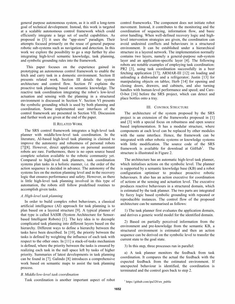
general purpose autonomous system, as it is still a long-term goal of technical development. Instead, this work is targeted at a scalable autonomous control framework which could efficiently integrate a large set of useful capabilities. As proposed in [3] it uses the “app-store” paradigm. Their attempts focused primarily on the reuse of general purpose robotic sub-systems such as navigation and detection. In this work we explore the possibility to go a step further by also integrating high-level semantic knowledge, task planning, and symbolic grounding rules into the framework.
This paper focuses on the experience gained in prototyping an autonomous control framework to enable the fetch and carry task in a domestic environment. Section II presents related work. Section III details the system architecture and control flow. Section IV explains the proactive task planning based on semantic knowledge. The reactive task coordination integrating the robot’s low-level actuation and sensing with the planning in a structured environment is discussed in Section V. Section VI presents the symbolic grounding which is used by both planning and coordination. Some implemented user interfaces of the control framework are presented in Section VII. Discussion and further work are given at the end of the paper.
II. RELATED WORK
The SRS control framework integrates a high-level task planner with middle/low-level task coordination. In the literature, AI-based high-level task planning is claimed to improve the autonomy and robustness of personal robots [7][8]. However, direct applications on personal assistant robots are rare. Furthermore, there is no open source based complete solution available to the robotic community yet. Compared to high-level task planners, task coordination systems plan tasks in a holistic manner, i.e. the order of the action sequence is decided in advance. The autonomy of the systems lies on the motion planning level and in the recovery logic that ensures performance and safety. However, as there is little high-level task planning involved in this type of automation, the robots still follow predefined routines to accomplish given tasks.
A. High-level task planning
In order to build complex robot behaviours, a classical
artificial intelligence (AI) approach for task planning is to
plan based on a layered structure [9]. A typical planner of
that type is called SASIR (System Architecture for Sensor-
based Intelligent Robots) [1]. The key idea is to decouple
complicated task planning into different layers based on the
hierarchy. Different ways to define a hierarchy between the
tasks have been described. In [10], the priority between the
tasks is defined by weighting the influence of each task with
respect to the other ones. In [11] a stack-of-tasks mechanism
is defined, where the priority between the tasks is ensured by
realizing each task in the null space left by tasks of higher
priority. Summaries of latest developments in task planning
can be found in [7]. Galindo [8] introduces a comprehensive
work based on semantic maps to assist the task planning
process.
B. Middle/low-level task coordination
Task coordination is another important aspect of robot
control frameworks. The component does not initiate robot movement. Instead, it contributes to the monitoring and the coordination of sequencing, information flow, and basic error handling. When well-defined recovery logic and high-level intervention strategies are given, the coordination can avoid undesired conflicts and behaviours in a structured environment. It can be established under a hierarchical structure in a layered network. The implementation normally contains two layers, namely a general-purpose sub-system layer and an application-specific layer [4]. The following robots are notable examples of employing task coordination: PR2 [3], using task coordination successfully in a beer fetching application [17]; ARMAR-III [12] on loading and unloading a dishwasher and a refrigerator; Justin [13] for manipulating objects on tables; Herb [14] for opening and closing doors, drawers, and cabinets, and also turning handles with human-level performance and speed; and Care-O-bot [16] before the SRS project, which can detect and place bottles onto a tray.
III. CONTROL STRUCTURE
The architecture of the system proposed by the SRS
project is an extension of the frameworks proposed in [1]
and [3] with a special focus on robustness and open source
based implementation. It has a modular structure, where
components at each level can be replaced by other modules
with the same interface. Hence, the framework can be
integrated with other robotic systems or knowledge systems
with little modification. The source code of the SRS
framework is available for download at GitHub1. The
structure is illustrated in Figure 2.
The architecture has an automatic high-level task planner,
which initialises actions on the symbolic level. The planner
is supported by a semantic knowledge base (KB) and a robot
configuration optimiser to produce proactive robotic
behaviours. It also has an action executive for coordination
of actions at the sensing and actuation level. The executive
produces reactive behaviours in a structured domain, which
is estimated by the task planner. The two parts are integrated
by fuzzy logic based symbolic grounding with repeated or
reproducible instances. The control flow of the proposed
architecture can be summarised as follows:
1) The task planner first evaluates the application domain,
and derives a generic world model for the identified domain.
2) Based on partially perceived information from the
environment and pre-knowledge from the semantic KB, a
structured environment is estimated and then an action
sequence can be derived on the symbolic level to transfer the
current state to the goal state.
3) In this step, three processes run in parallel:
a) A task planner monitors the feedback from task
coordination. It compares the actual the feedback with the
expected feedback from the estimated environment. If
unexpected behaviour is identified, the coordination is
terminated and the control goes back to step 2.
1 https://github.com/ipa320/srs_public
1652
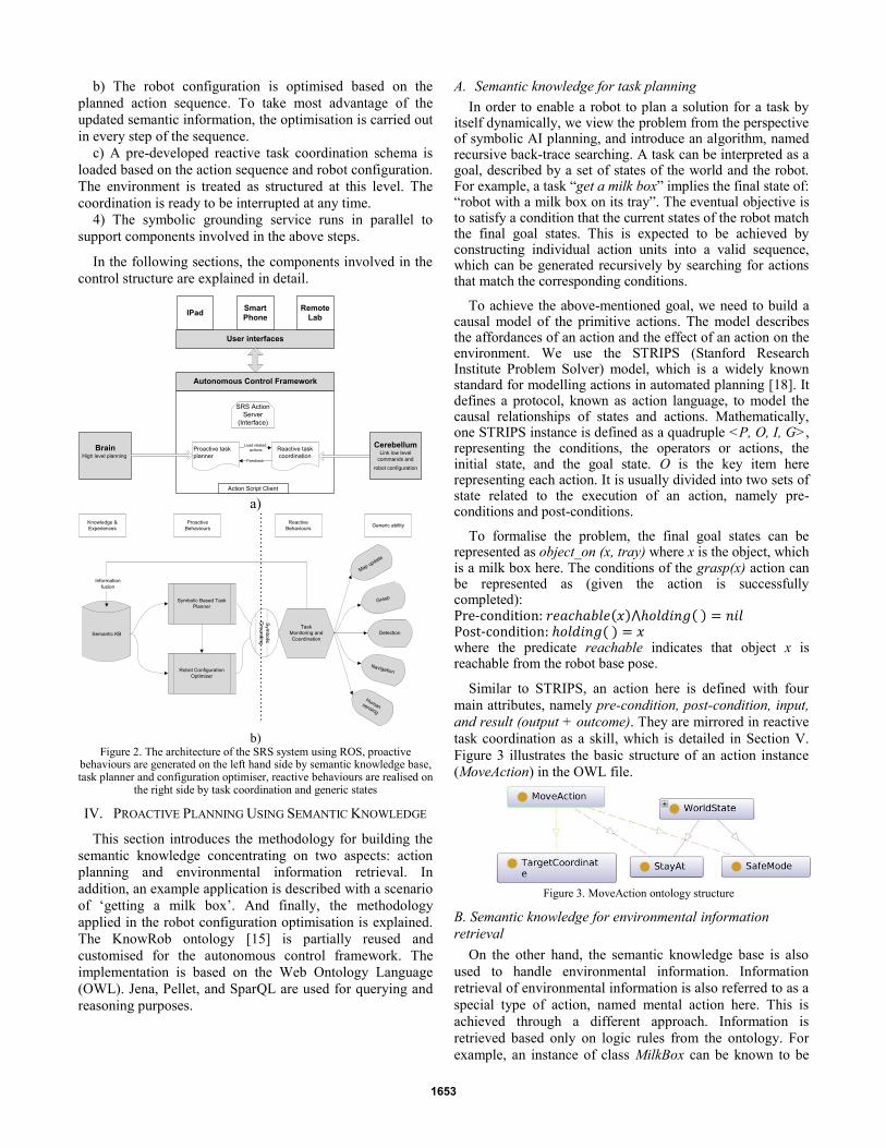
b) The robot configuration is optimised based on the
planned action sequence. To take most advantage of the
updated semantic information, the optimisation is carried out
in every step of the sequence.
c) A pre-developed reactive task coordination schema is
loaded based on the action sequence and robot configuration.
The environment is treated as structured at this level. The
coordination is ready to be interrupted at any time.
4) The symbolic grounding service runs in parallel to
support components involved in the above steps.
In the following sections, the components involved in the
control structure are explained in detail.
Autonomous Control Framework
Action Script Client
Proactive task
planner
Reactive task
coordination
SRS Action
Server
(Interface)
Load related
actionsCerebellum
Link low level
commands and
robot configuration
Feedback
BrainHigh level planning
User interfaces
IPadSmart
Phone
Remote
Lab
a)
Semantic KB
Symbolic Based Task
Planner
Robot Configuration
Optimiser
Task
Monitoring and
Coordination
Map update
Grasp
Detection
Navigation
Human sensing
Sym
bo
lic
Gro
un
din
g
Knowledge &
Experiences
Proactive
Behaviours
Reactive
BehavioursGeneric ability
Information
fusion
b)
Figure 2. The architecture of the SRS system using ROS, proactive behaviours are generated on the left hand side by semantic knowledge base, task planner and configuration optimiser, reactive behaviours are realised on
the right side by task coordination and generic states
IV. PROACTIVE PLANNING USING SEMANTIC KNOWLEDGE
This section introduces the methodology for building the
semantic knowledge concentrating on two aspects: action
planning and environmental information retrieval. In
addition, an example application is described with a scenario
of ‘getting a milk box’. And finally, the methodology
applied in the robot configuration optimisation is explained.
The KnowRob ontology [15] is partially reused and
customised for the autonomous control framework. The
implementation is based on the Web Ontology Language
(OWL). Jena, Pellet, and SparQL are used for querying and
reasoning purposes.
A. Semantic knowledge for task planning
In order to enable a robot to plan a solution for a task by itself dynamically, we view the problem from the perspective of symbolic AI planning, and introduce an algorithm, named recursive back-trace searching. A task can be interpreted as a goal, described by a set of states of the world and the robot. For example, a task “get a milk box” implies the final state of: “robot with a milk box on its tray”. The eventual objective is to satisfy a condition that the current states of the robot match the final goal states. This is expected to be achieved by constructing individual action units into a valid sequence, which can be generated recursively by searching for actions that match the corresponding conditions.
To achieve the above-mentioned goal, we need to build a causal model of the primitive actions. The model describes the affordances of an action and the effect of an action on the environment. We use the STRIPS (Stanford Research Institute Problem Solver) model, which is a widely known standard for modelling actions in automated planning [18]. It defines a protocol, known as action language, to model the causal relationships of states and actions. Mathematically, one STRIPS instance is defined as a quadruple <P, O, I, G>, representing the conditions, the operators or actions, the initial state, and the goal state. O is the key item here representing each action. It is usually divided into two sets of state related to the execution of an action, namely pre-conditions and post-conditions.
To formalise the problem, the final goal states can be represented as object_on (x, tray) where x is the object, which is a milk box here. The conditions of the grasp(x) action can be represented as (given the action is successfully completed): ( ) ( ) ( ) where the predicate reachable indicates that object x is reachable from the robot base pose.
Similar to STRIPS, an action here is defined with four
main attributes, namely pre-condition, post-condition, input,
and result (output + outcome). They are mirrored in reactive
task coordination as a skill, which is detailed in Section V.
Figure 3 illustrates the basic structure of an action instance
(MoveAction) in the OWL file.
Figure 3. MoveAction ontology structure
B. Semantic knowledge for environmental information
retrieval
On the other hand, the semantic knowledge base is also
used to handle environmental information. Information
retrieval of environmental information is also referred to as a
special type of action, named mental action here. This is
achieved through a different approach. Information is
retrieved based only on logic rules from the ontology. For
example, an instance of class MilkBox can be known to be
1653
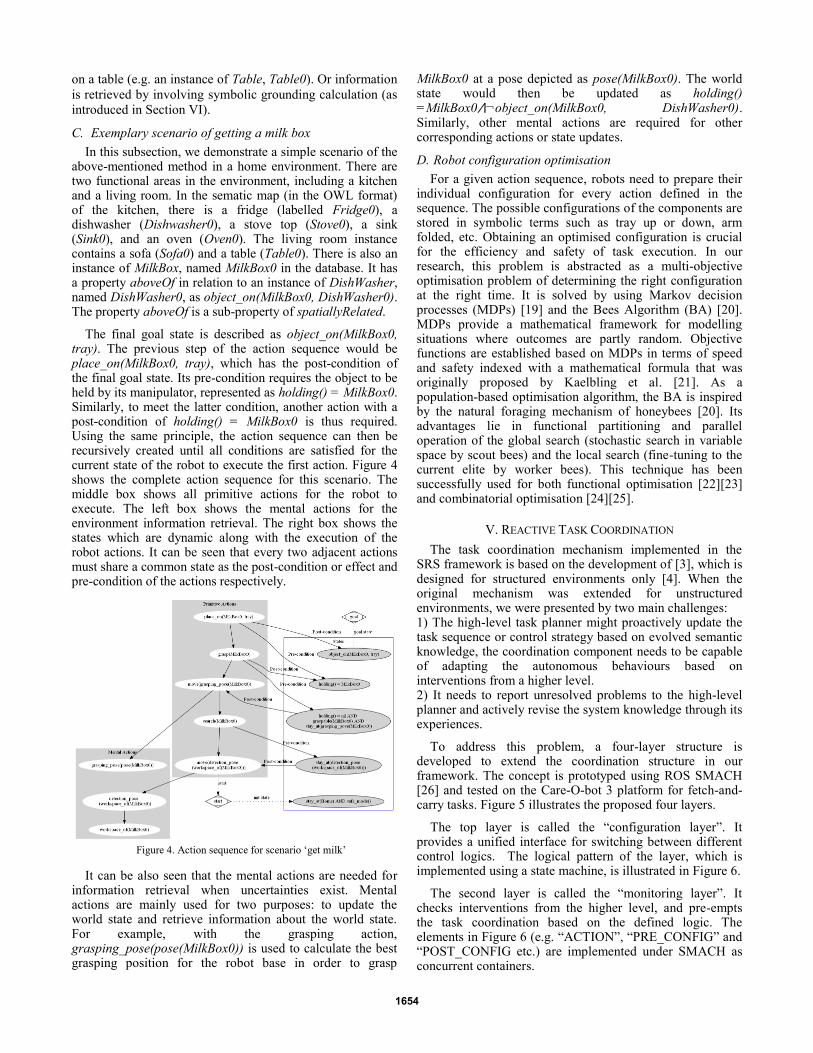
on a table (e.g. an instance of Table, Table0). Or information
is retrieved by involving symbolic grounding calculation (as
introduced in Section VI).
C. Exemplary scenario of getting a milk box
In this subsection, we demonstrate a simple scenario of the above-mentioned method in a home environment. There are two functional areas in the environment, including a kitchen and a living room. In the sematic map (in the OWL format) of the kitchen, there is a fridge (labelled Fridge0), a dishwasher (Dishwasher0), a stove top (Stove0), a sink (Sink0), and an oven (Oven0). The living room instance contains a sofa (Sofa0) and a table (Table0). There is also an instance of MilkBox, named MilkBox0 in the database. It has a property aboveOf in relation to an instance of DishWasher, named DishWasher0, as object_on(MilkBox0, DishWasher0). The property aboveOf is a sub-property of spatiallyRelated.
The final goal state is described as object_on(MilkBox0, tray). The previous step of the action sequence would be place_on(MilkBox0, tray), which has the post-condition of the final goal state. Its pre-condition requires the object to be held by its manipulator, represented as holding() = MilkBox0. Similarly, to meet the latter condition, another action with a post-condition of holding() = MilkBox0 is thus required. Using the same principle, the action sequence can then be recursively created until all conditions are satisfied for the current state of the robot to execute the first action. Figure 4 shows the complete action sequence for this scenario. The middle box shows all primitive actions for the robot to execute. The left box shows the mental actions for the environment information retrieval. The right box shows the states which are dynamic along with the execution of the robot actions. It can be seen that every two adjacent actions must share a common state as the post-condition or effect and pre-condition of the actions respectively.
Figure 4. Action sequence for scenario ‘get milk’
It can be also seen that the mental actions are needed for information retrieval when uncertainties exist. Mental actions are mainly used for two purposes: to update the world state and retrieve information about the world state. For example, with the grasping action, grasping_pose(pose(MilkBox0)) is used to calculate the best grasping position for the robot base in order to grasp
MilkBox0 at a pose depicted as pose(MilkBox0). The world state would then be updated as holding() =MilkBox0 ¬object_on(MilkBox0, DishWasher0). Similarly, other mental actions are required for other corresponding actions or state updates.
D. Robot configuration optimisation
For a given action sequence, robots need to prepare their individual configuration for every action defined in the sequence. The possible configurations of the components are stored in symbolic terms such as tray up or down, arm folded, etc. Obtaining an optimised configuration is crucial for the efficiency and safety of task execution. In our research, this problem is abstracted as a multi-objective optimisation problem of determining the right configuration at the right time. It is solved by using Markov decision processes (MDPs) [19] and the Bees Algorithm (BA) [20]. MDPs provide a mathematical framework for modelling situations where outcomes are partly random. Objective functions are established based on MDPs in terms of speed and safety indexed with a mathematical formula that was originally proposed by Kaelbling et al. [21]. As a population-based optimisation algorithm, the BA is inspired by the natural foraging mechanism of honeybees [20]. Its advantages lie in functional partitioning and parallel operation of the global search (stochastic search in variable space by scout bees) and the local search (fine-tuning to the current elite by worker bees). This technique has been successfully used for both functional optimisation [22][23] and combinatorial optimisation [24][25].
V. REACTIVE TASK COORDINATION
The task coordination mechanism implemented in the SRS framework is based on the development of [3], which is designed for structured environments only [4]. When the original mechanism was extended for unstructured environments, we were presented by two main challenges: 1) The high-level task planner might proactively update the task sequence or control strategy based on evolved semantic knowledge, the coordination component needs to be capable of adapting the autonomous behaviours based on interventions from a higher level. 2) It needs to report unresolved problems to the high-level planner and actively revise the system knowledge through its experiences.
To address this problem, a four-layer structure is developed to extend the coordination structure in our framework. The concept is prototyped using ROS SMACH [26] and tested on the Care-O-bot 3 platform for fetch-and-carry tasks. Figure 5 illustrates the proposed four layers.
The top layer is called the “configuration layer”. It provides a unified interface for switching between different control logics. The logical pattern of the layer, which is implemented using a state machine, is illustrated in Figure 6.
The second layer is called the “monitoring layer”. It checks interventions from the higher level, and pre-empts the task coordination based on the defined logic. The elements in Figure 6 (e.g. “ACTION”, “PRE_CONFIG” and “POST_CONFIG etc.) are implemented under SMACH as concurrent containers.
1654
“pre-configuration”, “post-configuration”, “main
operation” and “pause”
“checking during operation” and “checking during pause”
“approach pose”, “detect”, “environment update”, “pick object on table”,
“place object on tray”, “open door” etc.
“navigation”, “detection”, “grasp”, “map update”, “human
sensing” etc.
Configuration
layer
Monitoring
layer
Skill layer
Generic state
layer
smach.Statemachines
smach.Concurrence
smach.Statemachines
smach.State
Figure 5. Reactive task coordination structure
Fig. 6. State machine in configuration layer
Figure 7. Detection state machine
The third layer is the so called “skill layer”. This layer is equivalent to the application-specific layer in [4] but focuses more on reusable high-level skills, e.g. “pick up”, “environment update” and “detection”. These skills and their application contexts in terms of pre- and post-conditions are stored in the semantic KB as primitive actions. As detailed in Section IV, the primitive actions are the building blocks for the high-level task planner. Some primitive actions might have their own action hierarchy, this is realised as nested state machines in the layer. Figure 7 shows a breakdown of a general detection state machine which nests two state machines. DETECT_OBJECT-1 enables a robot moving around tables for searching table-top objects. DETECT_OBJECT-2 enables a robot to focus on multiple regions of a detected scene. Additionally, the coordination at this layer is not only for fine-tuning the robot activities in a well-known domain, but also for collecting experiences from sensory and actuator systems, and then reporting back to the semantic KB through output and outcome. This is reflected within the high-level task planner as the action result detailed in Section IV.
Finally, the generic state layer is at the bottom of the structure. It is equivalent to the general-purpose sub-system layer in [4]. The generic states normally contain some type of client which sends requests. Lower level robotic solutions such as navigation, manipulation, detection, etc., can respond to the requests as servers. The implementation is realised in the SRS framework with the support of ROS actionlib [27]. This practise also significantly reduces the work associated with integration and as a result improves the portability of the framework. Due to length constraints of this article, the methodologies applied in our subsystems will
not be detailed. Some applications of the implementation under ROS can be found in [3].
VI. SYMBOLIC GROUNDING
Symbolic grounding bridges high-level planning and actual robot sensing and actuation. Action commands generated at the planning level are represented by symbolic terms such as “near”, “far”, “on”, or “in”. These terms indicate the position of a robot with respect to a target object and a corresponding action. At actuation level, a robot is controlled based on trajectories that specify the positions of the robot in its workspace over time. It is necessary to convert the symbolic terms used in high-level commands to specific positions so that trajectories can be generated at the actuation level. Reversely, continuous sensor outputs can be translated back to discrete symbolic terms for updating the semantic knowledge.
The grounding problem is a bottleneck for the integration of traditional AI-based task planners with personal assistant robots. This is mainly because of two reasons: 1) Symbolic terms such as “near” have different meanings and contexts in different actions. Even for the same action, they have different meanings for different objects; 2) In unstructured domestic environments uncertainties will exist. Hence the term “near” can indicate different positions in different cases.
Symbolic grounding has drawn increased attention from the research community. Reported research can be classified into learning based methods and vision based. In [28] a statistics-based approach was introduced, which calculates the probability distributions of symbolic terms to control parameters. [29] suggested letting a robot learn a suitable position for grasping using reinforcement learning. Based on the concept of Object-Action Complexes (OACs) [30], if an object and an action are fixed, the symbolic concepts can be considered as repeated, reproducible instances. Therefore, OACs can be used as a basis for grounding. To tackle the uncertainty of the unstructured environment, symbolic grounding is treated as a fuzzy optimisation problem where the fuzzy rules are formulated using OACs in our framework. The selection of the fuzzy approach is mainly for two of its advantages: 1) Due to the shape of membership functions, a fuzzy system is generally robust to uncertainties [31]; 2) Uncertainties may come from various sources. Fuzzy systems can be highly efficient on aggregating the effects of different sources – e.g. for the selection of the base pose of a grasp, the source can be target position, shape/position of identified obstacles, etc.
Figure 8. Optimal grasping position identified by the robot
Fuzzy set theory [31] is applied to establish the objective function, to model fuzzy constraints, and to perform fuzzy
1655
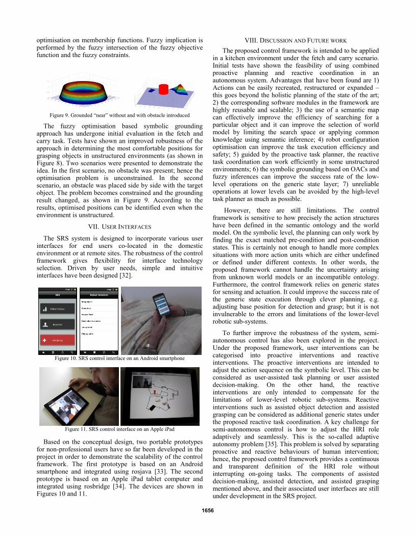
optimisation on membership functions. Fuzzy implication is performed by the fuzzy intersection of the fuzzy objective function and the fuzzy constraints.
Figure 9. Grounded “near” without and with obstacle introduced
The fuzzy optimisation based symbolic grounding approach has undergone initial evaluation in the fetch and carry task. Tests have shown an improved robustness of the approach in determining the most comfortable positions for grasping objects in unstructured environments (as shown in Figure 8). Two scenarios were presented to demonstrate the idea. In the first scenario, no obstacle was present; hence the optimisation problem is unconstrained. In the second scenario, an obstacle was placed side by side with the target object. The problem becomes constrained and the grounding result changed, as shown in Figure 9. According to the results, optimised positions can be identified even when the environment is unstructured.
VII. USER INTERFACES
The SRS system is designed to incorporate various user interfaces for end users co-located in the domestic environment or at remote sites. The robustness of the control framework gives flexibility for interface technology selection. Driven by user needs, simple and intuitive interfaces have been designed [32].
Figure 10. SRS control interface on an Android smartphone
Figure 11. SRS control interface on an Apple iPad
Based on the conceptual design, two portable prototypes for non-professional users have so far been developed in the project in order to demonstrate the scalability of the control framework. The first prototype is based on an Android smartphone and integrated using rosjava [33]. The second prototype is based on an Apple iPad tablet computer and integrated using rosbridge [34]. The devices are shown in Figures 10 and 11.
VIII. DISCUSSION AND FUTURE WORK
The proposed control framework is intended to be applied in a kitchen environment under the fetch and carry scenario. Initial tests have shown the feasibility of using combined proactive planning and reactive coordination in an autonomous system. Advantages that have been found are 1) Actions can be easily recreated, restructured or expanded – this goes beyond the holistic planning of the state of the art; 2) the corresponding software modules in the framework are highly reusable and scalable; 3) the use of a semantic map can effectively improve the efficiency of searching for a particular object and it can improve the selection of world model by limiting the search space or applying common knowledge using semantic inference; 4) robot configuration optimisation can improve the task execution efficiency and safety; 5) guided by the proactive task planner, the reactive task coordination can work efficiently in some unstructured environments; 6) the symbolic grounding based on OACs and fuzzy inferences can improve the success rate of the low-level operations on the generic state layer; 7) unreliable operations at lower levels can be avoided by the high-level task planner as much as possible.
However, there are still limitations. The control framework is sensitive to how precisely the action structures have been defined in the semantic ontology and the world model. On the symbolic level, the planning can only work by finding the exact matched pre-condition and post-condition states. This is certainly not enough to handle more complex situations with more action units which are either undefined or defined under different contexts. In other words, the proposed framework cannot handle the uncertainty arising from unknown world models or an incompatible ontology. Furthermore, the control framework relies on generic states for sensing and actuation. It could improve the success rate of the generic state execution through clever planning, e.g. adjusting base position for detection and grasp; but it is not invulnerable to the errors and limitations of the lower-level robotic sub-systems.
To further improve the robustness of the system, semi-autonomous control has also been explored in the project. Under the proposed framework, user interventions can be categorised into proactive interventions and reactive interventions. The proactive interventions are intended to adjust the action sequence on the symbolic level. This can be considered as user-assisted task planning or user assisted decision-making. On the other hand, the reactive interventions are only intended to compensate for the limitations of lower-level robotic sub-systems. Reactive interventions such as assisted object detection and assisted grasping can be considered as additional generic states under the proposed reactive task coordination. A key challenge for semi-autonomous control is how to adjust the HRI role adaptively and seamlessly. This is the so-called adaptive autonomy problem [35]. This problem is solved by separating proactive and reactive behaviours of human intervention; hence, the proposed control framework provides a continuous and transparent definition of the HRI role without interrupting on-going tasks. The components of assisted decision-making, assisted detection, and assisted grasping mentioned above, and their associated user interfaces are still under development in the SRS project.
1656

ACKNOWLEDGMENT
The work presented in this paper was conducted as part of the project “SRS - Multi-Role Shadow Robotic System for Independent Living”, which is funded by the European Commission under Framework Programme 7.
REFERENCES
[1] C.X. Chen, and M.M. Trivedi, "Task planning and action coordination
in integrated sensor-based robots". IEEE Transactions on Systems,
Man and Cybernetics, 1995, 25(4), 569-591 [2] R. Qiu, A. Noyvirt, Z. Ji, A. Soroka, D. Li, B. Liu, A. Georg, F.
Weisshardt, S. Xu, "Integration of Symbolic Task Planning into
Operations within an Unstructured Environment", International Journal of Intelligent Mechatronics and Robotics, 2012, 2(2), 128-147,
April-June [3] J. Bohren, R.B. Rusu, E.G. Jones, E. Marder-Eppstein, C. Pantofaru,
M. Wise, L. Mösenlechner, W. Meeussen, and S. Holzer, "Towards
autonomous robotic butlers: Lessons learned with the PR2", in Proc. ICRA, 2011, pp.5568-5575.
[4] J. Bohren, and S. Cousins, "The SMACH High-Level Executive"
Robotics & Automation Magazine, IEEE, vol.17, no.4, pp.18-20, Dec. 2010
[5] M. Quigley, B. Gerkey, K. Conley, J. Faust, T. Foote, J. Leibs, E.
Berger, R. Wheeler, and A. Y. Ng, "ROS: an open-source Robot Operating System". ICRA 2009 Workshop on Open Source Software
[6] B. Graf, U. Reiser, M. Hagele, K. Mauz, P. Klein, "Robotic home
assistant Care-O-bot® 3 - product vision and innovation platform" Advanced Robotics and its Social Impacts (ARSO), 2009 IEEE
Workshop on , vol., no., pp.139-144, 23-25 Nov. 2009
[7] H. Zender, "An integrated robotic system for spatial understanding and situated interaction in indoor environments". In Proceedings of the
Twenty-Second Conference on Artificial Intelligence (AAAI-2007),
(pp. 1584-1589) [8] C. Galindo, J.-A. Fernández-Madrigal, J. Gonzalez, and A. Saffiotti,
"Robot Task Planning using Semantic Maps", Robotics and
Autonomous Systems, 2008, 56, 955–966. [9] N. Mansard and F. Chaumette, "Task Sequencing for High-Level
Sensor-Based Control". IEEE Transactions on Robotics, 2007, 23(1),
60–72 [10] W. Decre, R. Smits, H. Bruyninckx and J. De Schutter., "Extending
iTaSC to support inequality constraints and non-instantaneous task
specification", IEEE International Conference on Robotics and Automation (ICRA’2009) (pp. 1875–1882). Piscataway, NJ, USA:
IEEE Press
[11] A. Escande, N. Mansard, and P.B. Wieber, "Fast resolution of hierarchized inverse kinematics with inequality constraints". In IEEE
International Conference on Robotics and Automation (ICRA’2010)
(pp. 3733–3738). Anchorage, USA
[12] T. Asfour, P. Azad, N. Vahrenkamp, K. Regenstein, A. Bierbaum, K.
Welke, J. Schröder, and R. Dillmann. "Toward humanoid
manipulation in human-centred environments". Robot. Auton. Syst. 56, 1 (January 2008), 54-65.
[13] M. Fuchs, C. Borst, P. R. Giordano, A. Baumann, E. Kraemer, J.
Langwald. "Rollin' Justin - Design considerations and realization of a mobile platform for a humanoid upper body" in Proceedings of the
IEEE International Conference on Robotics and Automation 2009
[14] S.S. Srinivasa, D. Ferguson, C. J. Helfrich, D. Berenson, A. Collet, R. Diankov, G. Gallagher, G. Hollinger, J. Kuffner, and M. V. Weghe.
2010. "HERB: a home exploring robotic butler". Auton. Robots 28, 1
January 2010 [15] M. Tenorth and M. Beetz, "Knowrob — knowledge processing for
autonomous personal robots" in Proc. IEEE/RSJ Int. Conf. Intelligent
Robots and Systems IROS 2009, 2009, pp. 4261–4266 [16] M. Meeussen; M. Wise; S. Glaser; S. Chitta; C. McGann, P. Mihelich,
E. Marder-Eppstein, M. Muja, V. Eruhimov, T. Foote, J. Hsu, R.B. Rusu, B. Marthi, G. Bradski, K. Konolige, B. Gerkey, E. Berger,
"Autonomous door opening and plugging in with a personal robot"
Robotics and Automation (ICRA), 2010 IEEE International Conference on , vol., no., pp.729-736, 3-7 May 2010
[17] U. Reiser, C. Connette, J. Fischer, J. Kubacki, A. Bubeck, F.
Weisshardt, T. Jacobs, C. Parlitz, M. Hagele, A. Verl, "Care-O-bot® 3
- creating a product vision for service robot applications by integrating design and technology" Intelligent Robots and Systems, 2009. IROS
2009. IEEE/RSJ International Conference on , vol., no., pp.1992-
1998, 10-15 Oct. 2009 [18] R.E. Fikes and N.J. Nilsson, "Strips: A new approach to the
application of theorem proving to problem solving", Artificial
Intelligence, vol. 2, no. 3-4, pp. 189–208, 1971 [19] G. Theocharous and S. Mahadevan, "Approximate planning with
hierarchical partially observable Markov decision process models for
robot navigation", Robotics and Automation, 2002. Proceedings. ICRA '02. IEEE International Conference on , vol.2, no., pp.1347-
1352, 2002
[20] D.T. Pham, A. Ghanbarzadeh, E. Koç, S. Otri, S. Rahim, and M. Zaidi, "The Bees Algorithm -- A novel tool for complex optimisation
problems", in Proceedings of the 2nd International Virtual Conference
on Intelligent Production Machines and Systems (IPROMS 2006), Cardiff, UK, 2006, pp. 454-459
[21] P.L. Kaelbling, M. L. Littman, and A. R. Cassandra, "Planning and
acting in partially observable stochastic domains", Artificial Intelligence, 1998, 101, 99-134
[22] D.T. Pham, A. Ghanbarzadeh, S. Otri and E. Koç., "Optimal design of
mechanical components using the Bees Algorithm", Proceedings of the Institution of Mechanical Engineers, Part C: Journal of Mechanical
Engineering Science, vol. 223, pp. 1051-1056, 2009
[23] S. Xu, F. Yu, Z. Luo, Z. Ji, D.T. Pham, R. Qiu, "Adaptive Bees Algorithm -- Bioinspiration from honeybee foraging to optimize fuel
economy of a semi-track air-cushion vehicle", The Computer Journal,
vol. 54, pp. 1416-1426, 2011 [24] D.T. Pham, A. Afify and E. Koc, "Manufacturing cell formation using
the Bees Algorithm" in Proceedings of the 3rd International Virtual
Conference on Intelligent Production Machines and Systems (IPROMS 2007), Cardiff, UK, 2007, pp. 523-528
[25] S. Xu, Z. Ji, D. T. Pham and F. Yu, "Bio-inspired binary bees
algorithm for a two-level distribution optimisation problem", Journal
of Bionic Engineering, vol. 7, pp. 161-167, 2010
[26] J. Bohren (2012). Wiki: smach, last edited 2010-10-14 from
http://www.ros.org/wiki/smach [27] E Marder-Eppstein.and V. Pradeep (2012). Wiki: actionlib, last edited
2011-12-26 from www.ros.org/wiki/actionlib [28] N. Mavridis, and D. Roy, "Grounded situation models for robots:
where words and perception meet", In Proceedings of the IEEE/RSJ
International Conference on Intelligent Robots and Systems (IROS), pp. 4690-4697, China, 2006
[29] M. Tenorth and M. Beetz, "Towards practical and grounded
knowledge representation systems for autonomous household robots", 1st International Workshop on Cognition for Technical Systems,
Germany, 2008
[30] N. Krüger, J. Piater, F. Wörgötter, C. Geib, R. Petrick, M. Steedman, A. Ude, T. Asfour, D. Kraft, D. Omrcen, B. Hommel, A. Agostino, D.
Kragic, J. Eklundh, V. Krüger, and R. Dillmann (2009). "A Formal
Definition of Object Action Complexes and Examples at different Levels of the Process Hierarchy". Technical report, EU project
PACO-PLUS
[31] D.T. Pham and R. Qiu, "Functional analysis and T-S fuzzy system design", IFAC World Congress, 2004, Volume 16, Part 1
[32] M. Mast, M. Burmester, K. Krüger, S. Fatikow, G. Arbeiter, B. Graf,
G. Kronreif, L. Pigini, D. Facal, and R. Qiu. "User-centered design of a dynamic-autonomy remote interaction concept for manipulation-
capable robots to assist elderly people in the home", Journal of
Human-Robot Interaction, 2012, vol. 1. [33] K. Damon (2012). Wiki: rosjava, last edited 2012-02-03 from
www.ros.org/wiki/rosjava
[34] T.J. Graylin (2012). Wiki: rosbridge last edited 2011-12-09 from www.ros.org/wiki/rosbridge
[35] A. Fereidunian, M. Lehtonen, H. Lesani, C. Lucas, M. Nordman,
2007. "Adaptive autonomy: smart cooperative cybernetic systems for
more humane automation solutions", In Proc. of the IEEE Int. Conf. of
SMC07, Montreal, Canada.
1657
978-1-4673-0311-8/12/$31.00 ©2012 IEEE
Human detection and tracking in an assistive living service robot through multimodal data fusion
Alexandre Noyvirt, Renxi Qiu School of Engineering
Cardiff University UK
{NoyvirtA, QiuR}@cf.ac.uk
Abstract—A new method is proposed for using a combination of measurements from a laser range finder and a depth camera in a data fusion process that benefits from each modality’s strong side. The combination leads to a significantly improved performance of the human detection and tracking in comparison with what is achievable from the singular modalities. The useful information from both laser and depth camera is automatically extracted and combined in a Bayesian formulation that is estimated using a Markov Chain Monte Carlo (MCMC) sampling framework. The experiments show that this algorithm can track robustly multiple people in real world assistive robotics applications.
Keywords—human detection, human tracking, service robotics, assistive technology, MCMC, sensor data fusion.
I. INTRODUCTION
Robust human tracking has applications that span many domains of life. In service robotics the controlling algorithms of a robot need to be constantly aware of the location of the local user in order to be able to interact with the human effectively. The task of detecting and tracking people in robot surroundings has recently been greatly simplified by the introduction of real-time depth cameras. However, even the best systems in existence today still exhibit limitations associated with their inability to track humans from a moving platform due to the loss of depth resolution at longer distances, low accuracy and relatively high noise levels. In contrast, the laser range finders are much more accurate, more reliable at longer distances and produce measurements with low noise levels when compared with the depth cameras. However, normally they can only measure a single point at a time, which limits their ability to capture the full picture at once to enable its interpretation. This is a severely limiting factor for their application when dealing with dynamic targets like moving people. Typically, both types of sensor are present in a service robot as the laser is used for safety and environment map building and the depth camera is used for object detection. Our aim has been to combine the strengths of both sensor modalities, the precision, the low noise and the wide field of view of a laser finder with the speed and full frame sensing of a depth camera, to build a reliable human detector and tracker system for the needs of service robotics.
In this paper, we propose a Bayesian system that integrates two complementary sensor modalities, i.e. RGB-D and laser data, by using a probabilistic upper body shape detector and a
leg detector. The system can easily be extended to include additional modalities like color images.
Our contribution in this work is: 1) a method for extracting useful information from laser and RGB-D data for human detection and tracking in a mobile robotic application; 2) an effective MCMC based algorithm for tracking multiple people in assistive robotics applications.
II. RELATED WORK
The automatic analysis of human motion has been studied extensively as surveyed in [1]. In robotics, although the issue of detecting people in 2D range data has been addressed by many researchers, human detection in 3D point cloud data is still a relatively recent problem with little related work. The work presented in [2] detects people in point clouds from stereo vision by processing vertical objects using a fixed pedestrian model. In [3], the 3D scan is collapsed into a virtual 2D slice to classify a person by a set of SVM classified features. While both works require a ground plane assumption this limitation is overcome in [4] via a voting approach of classified parts and a top-down verification procedure that learns an optimal set of features in a boosted volume tessellation.
In computer vision the problem of detecting humans from single images has been extensively studied as well. Part based voting or window scrolling methods have been reported [5], [6], [7], [8], [9]. Single depth images have been used in [10] for human pose recognition in the game industry. The authors of [11] have reported very good results in applying Implicit Shape Models (ISM) for the detection of people in crowded scenes. Other works, similarly to us, address the problem of multi-modal people detection: [12] proposes a trainable 2D range data and color camera, [13] uses a stereo system to combine image data, disparity maps and optical flow, and [14] uses intensity images and a time-of-flight camera. However, none of above addresses the problem that we focus on, i.e. how to enhance the measurements of a depth camera, e.g. a Microsoft Kinect sensor, with extracted information from a 2D laser range finder to achieve improved human tracking characteristics.
III. BAYESIAN FORMULATION
Our goal is to detect and track a variable number of people from a sequence of laser scans, depth images and color images.
978-1-4673-0311-8/12/$31.00 ©2012 IEEE 1176

We formulate a sequential tracking problem as computing the maximum a posteriori (MAP) X∗ such that:
X∗ argmax ∈ P X|Y , (1)
where X X ,… , X is the state sequence and YY , … , Y is the observation sequence. Let X X , X ,… , X be a set of K people, referred as tracking targets, at time t. A basic Bayesian sequential estimation can be described as a two step recursion as follows:
Prediction step:
| ~ | | ~ (2)
Filtering step:
P X |Y ~ | | ~
| (3)
After substitution we obtain:
P X |Y ~ ∝ P Y |X P X |X P X |Y ~ dX
(4)
where P Y |X represents the observation likelihood at time t, P X |X represents the motion prior and P X |Y ~ represents the posterior at time t-1.
To start the process the recursion has to be initialized with a distribution for the initial stateP X . Assuming independent motion between the targets, the observation likelihood P Y |X and the motion prior P X |X can be factorized as follows:
P Y |X P Y X (5)
P X |X P X X (6)
where M indicates the number of targets at time t.
Since none of the individual detectors used by us gives a reliable detection on its own we incorporate multiple weak detectors to get stronger confidence value about the presence of people in the scene. Assuming independence of the observations of the targets, the observation likelihood can be rewritten as:
P Y |X P Y X
(7)
where jis the index of the weak detector, Nis the number of the weak detectors in the system, and X is a 3D location of the person i observed by the weak detectorj.
A. State model
The state vector , at time , consists of the individuals states , , where , , are the 3D coordinates of person . Since new people can appear or disappear at any time, e.g. walk in or walk out the room, the dimension of the state vector is variable. This should be taken into account when computing the maximum a posteriori (1) since not all numerical approximation methods for Bayesian Sequential tracking can handle a variable dimension state.
B. Dynamic Model
In our tracking system we use a constant velocity model which can be described by a second order autoregressive equation as follows:
, , , (8)
where , , are matrices that are learned in experiments and represents the noise, modelled as standard normal distribution that is centred on the location of the target at time 1.
IV. OBSERVATION MODELS
It is a typical setup for the majority of available robot platforms to use laser and RGB-D sensors for observation of the environment in which a service robot operates. Since each sensor has different properties we employ a separate observation model to extract information from them that is useful for human detection.
A. Laser Based Observation
Laser scanners offer high accuracy, low noise and a wider field of view in comparison with the depth cameras. However, since they can achieve scan rates of only a few scans per second they are not suitable for detecting rapid dynamic changes in the environment. In an approach inspired by [15] we developed a leg detector algorithm that uses 2D laser range data to detect human legs. A typical laser range scanner produces scans in lines made of sequences of point measurements in a single plane. While it is possible to mount the laser scanner on a tilting table and to produce a 3D point cloud by varying the tilt angle of the table this is not considered a practical solution for dynamic scenes as it increases the scanning time even further and violates the safety equipment regulations requirements for fixed safety devices. The measured points in a scan represent the distances from the sensor to surfaces in the environment at fixed angular increments of the beam. Our algorithm uses a set of geometric features, extracted from the range data, to do a binary classification and determine or reject the presence of human legs.
In the first step of the algorithm, each scan line is divided into smaller segments using the Jump Distance Clustering (JDC) algorithm as described in detail by [15]. JDC initializes a new segment each time the distance between two consecutive points exceeds a certain threshold. As a result, the
1177
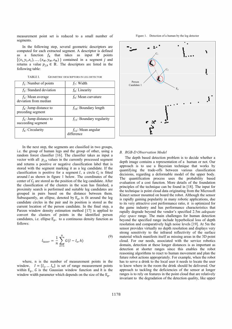
measurement point set is reduced to a small number of segments.
In the following step, several geometric descriptors are computed for each extracted segment. A descriptor is defined as a function that takes as input points
, , , … , , , contained in a segment and returns a value , ∈ . The descriptors are listed in the following table:
TABLE I. GEOMETRIC DESCRIPTORS IN LEG DETECTOR
: Number of points : Width
: Standard deviation : Linearity
: Mean average deviation from median
: Mean curvature
: Jump distance to preceding segment
: Boundary length
: Jump distance to succeeding segment
: Boundary regularity
: Circularity : Mean angular difference
In the next step, the segments are classified in two groups, i.e. the group of human legs and the group of other, using a random forest classifier [16]. The classifier takes as input a vector with all , values in the currently processed segment and returns a positive or negative classification label that is stored with the segment marking it as a leg candidate. If the classification is positive for a segment , a circle is fitted around as shown in figure 1 below. The coordinates of the center of are stored as the position of the leg candidate. After the classification of the clusters in the scan has finished, a proximity search is performed and suitable leg candidates are grouped in pairs based on the distance between them. Subsequently, an ellipse, denoted by Ε , is fit around the leg candidate circles in the pair and its position is stored as the current location of the person candidate. In the final step, a Parzen window density estimation method [17] is applied to convert the clusters of points in the identified person candidates, i.e. ellipse Ε , to a continuous density function as follows:
1 ,
(9)
where, n is the number of measurement points in the window, , … is set of range measurement points within Ε , is the Gaussian window function and is the window width parameter which depends on the size of the Ε .
Figure 1. Detection of a human by the leg detector
C1
C2
Ep
PersonCandidate 1
B. RGB-D Observation Model
The depth based detection problem is to decide whether a depth image contains a representation of a human or not. Our approach is to use a Bayesian technique that works by quantifying the trade-offs between various classification decisions, regarding a deformable model of the upper body. The quantification process uses the probability based evaluation of a cost function. More details of the foundation principles of the technique can be found in [18]. The input for the technique is point cloud data originating from the Microsoft Kinect sensor mounted on board the robot. Although the sensor is rapidly gaining popularity in many robotic applications, due to its very attractive cost performance ratio, it is optimized for the game industry and has performance characteristics that rapidly degrade beyond the vendor’s specified 2.5m adequate play space range. The main challenges for human detection beyond the specified range include hyperbolical loss of depth resolution and comparatively high noise levels [19]. At 5m the sensor provides virtually no depth resolution and displays very strong sensitivity to the infrared reflectivity of the surface material which manifests itself as missing areas in the 3D point cloud. For our needs, associated with the service robotics domain, detection at these longer distances is as important as detection at shorter ranges since this enables the robot reasoning algorithms to react to human movement and plan the future robot actions appropriately. For example, when the robot has to serve a drink to the local user it needs to locate the user to know where in the room the drink should be delivered. Our approach to tackling the deficiencies of the sensor at longer ranges is to rely on features in the point cloud that are relatively invariant to the degradation of the detection quality, like upper
1178
body shape, and to use additional cues from the laser range finder which is able to detect at longer distances.
The first step in the RGB-D algorithm is to remove the uninteresting regions in the point cloud, e.g. floor, walls and other planar surfaces from the cloud, and segmentation of the remaining data into regions using an adaptive segmentation algorithm. Both actions are performed using standard tools in the Point Cloud Library [20]. Subsequently, the algorithm removes the gaps in each segmented region by reconstructing the area using a non uniform rational B-splines algorithm.
For the second step, we have designed a probabilistic algorithm that uses a waist-torso-head-neck deformable template to achieve an optimal match to the region . The algorithm takes a segmented depth region and produces an optimal pose configuration denoted by , , , . In the waist is represented by a triangle denoted by . The torso is represented by a rectangular box denoted by parameters , , , , where and are the width and height of the torso, is the inclination angle of the torso in the image plane relative to the upright posture and is the rotation angle around the axis; The neck is presented by a trapezoid denoted by parameters , , , where and are the lengths of the parallel sides and is the height. The head is represented by a circle denoted by , where
is the radius of the circle. We take into account the human variations across the population by introducing probability distribution functions (pdf) for the template parameters.
Let , . . , , , , , , , , , be a set of distribution parameters used to define the probabilistic deformable template, where corresponds to parameters in functions describing the likelihood of detecting the template and , are the mean and standard deviations in the associated prior distribution functions. The parameters are learned from training examples.
Overall, the problem that we have to solve is to decide if a segmented region , includes a person (hypothesis ) or it contains only background representation (hypothesis ). Let
be the loss for wrong decision when the true state is . Also let | be the conditional probability distribution of the observing region, , when the true state is ,i.e. there is a person in that region, and let be the priori probability of state , then, as according to [18] a simple decision rule can be formulated as:
Decide that there is a human in the region of the point cloud, i.e. hypothesis , if:
| |
(10)
If we assume a uniform priori, we can further simplify the rule for detecting a human:
||
(11)
where represents a constant value.
In our approach we determine an optimal deformable template configuration that best fits into a segmented region from point cloud data. The approach for achieving the best fit is based on minimization of the sum of the false positive pixels, i.e. pixels that are covered by the template but not in the region, and the false negative pixels, i.e. pixels not covered in the template but present in the region. Then using a pre-trained binary classifier the algorithm decides whether there is a representation of a human or not.
Let | , be the likelihood to observe the region given the deformable template and the parameters , let
| be the prior of the template configurations.
Given a region we evaluate the optimal pose configuration that best fits our template into the region. To do this, we compute | , , i.e. the likelihood that region would have been produced by the depth sensor, given the template and the assumption of the parameters.
From the Bayes’ rule we can write:
| , ∝ | , | (12)
Assuming independence of the image likelihood functions we obtain:
| | ) | ) | ) r| ) (13)
Assuming that the separate priors have characteristics of normal distributions we obtain:
| η , (14)
| η , (15)
| η , (16)
| η , (17)
Assuming that the parts are independent we can factorize:
| , | | | | (18)
For the likelihood functions of the separate parts we use a distribution functions as follows:
| (19)
| (20)
| (21)
| (22)
where, , , , , , are
the number of false positive and false negative pixels in the match between the region and the template for the waist,
1179

torso, neck and head respectively. For example, if the template matches all the points in the region than there will be no false positive and negative pixels and the exponential function in (18-20) above will result in 1, i.e. the maximum probability that the region is a result of the template.
The output configuration M for the region is accepted if the likelihood function | , is above a certain threshold.
_, log | ,
, otherwise (23)
where the threshold parameter, , is linked with the constant in (11) and is determined empirically in experiments.
Once the algorithm has arrived at the optimal configuration of the template for the region we check whether the estimated parameters, i.e. , , , , , belong to a human by using a SVM binary classifier pre-trained with annotated depth images of people.
If the template parameters are classified as belonging to a human we incorporate the depth detector response into the overall human detection algorithm by projecting the current region into the 2D room coordinate system using a suitable transformation from the robot operating system.
The detection likelihood must favor positions close to the location of the detected human. Also detections that have achieved a high extent of fitting of the template into the depth region result in higher confidence.
We evaluate the log likelihood function for depth data as:
| 1
(24)
where , , respectively is the number of false positive, false negative, true positive pixels in the match, is a normalisation coefficient and is the image projection function of the hypothesis, and is hypothesis rectangle.
V. NUMERICAL APPROXIMATION
Loosely inspired by [21] we use a reversible-jump Markov Chain Monte Carlo (RJ MCMC) method for the Bayesian sequential estimation as it allows the simulation of the posterior distribution on spaces of varying dimensions. The simulation is possible even when the number of parameters in the model is not known or variable, as it is in our case. We approximate the distribution | ~ from (4) using RJ MCMC approximation with S samples:
| ~ | ∑ | ~ (25)
where Z is the partition function, | is the observation likelihood at time , | ~ is person
dynamics and each sample defines a valid multi-person configuration. Samples from Eq.4 are drawn via RJ MCMC with four move types: birth, death, update and swap.
Birth increases the model order with 1, Death is inverse, Update changes a target’s position, and Swap swaps identities for a pair of targets.
The birth move’s proposal distribution ∙ keeps all current objects fixed and assigns non-zero probability to configurations containing a new sample ∗. The interaction , prevents states of multiple people from collapsing
onto a single location.
The death move’s proposal distribution ∙ assigns non-zero probability to configurations in which all objects are fixed and ∗ has been removed.
The update move’s proposal distribution incorporates target dynamics | ~ for target ∗ while all other targets are fixed.
The Swap move’s proposal distribution swaps two targets’ state values and histories, keeping the rest fixed.
Since direct sampling is difficult, following the Metropolis Hasting algorithm [22] we compute the acceptance ratio of a new sample by the product of three ratios:
|
|
| ~
| ~
;
; (25)
where: ( 1 ) and in superscript denote proposed sample and the previous sample respectively, ; is the proposal density which depends on the current state to generate the new proposed sample, the first term expresses the ratio between the image likelihoods for the proposed sampleand the previous sample, the second term represents the ratio between approximated predictions and the last encodes the ratio between proposal distribution.
VI. EXPERIMENTAL EVALUATION
Experiments were performed in an indoor environment on the Care-o-bot 3 robotic platform which has a Kinect sensor, mounted at a height of 1.5 meters, and two SICK 300 safety lasers, mounted at the front and the back of the platform at a height of 10 cm. A number of people were walking around the robot while we were acquiring data simultaneously from the laser and the Kinect sensor together with the output from our algorithm. Later, using the recorded data we manually annotated the position of the people on the 2D map with a bounding box around each person and compared the coordinates with the output from the joint detector to evaluate the ratio of false positive and false negative detections.
To verify any improvement that the joint detector brings over the leg detector we compared their performance in terms of number of errors, i.e. false positive and false negative detections. We did this by selecting randomly 500 non-consecutive frames from the recorded files. In these frames up to four people were present. The results of the comparison are given in the following table:
1180

TABLE II. COMPARISON BETWEEN THE JOINT DETECTOR AND THE LEG DETECTOR
Leg detector only (laser)
Shape detector (RGB-D)
Joint detector
False Negatives (%)
3.3 3.7 1.4
False Positives (%)
8.05 2.4 1.1
The Leg detector alone was giving very high false positive results due to the fact that it was confusing corners and pieces of furniture for human legs. Switching to the joint detector improved detection rates substantially.
The experiments were performed on an Intel i7 920, 2.66 GHz computer using 1000 particles. The algorithm works at rate of 2.5 frames per second as this was the rate of the laser scanner. Further improvements, like transferring some of the computation to a GPU, will allow us to accelerate the computation and be able to perform two or more updates of the MCMC filter between each scan of the laser range finder.
VII. CONCLUSION AND FUTURE WORK
In this paper, we proposed a promising method that combines the strong sides of sensing in two modalities, i.e. laser and RGB-D. The system is able to detect and track a varying number of people in a typical service robot scenario. The experiments carried out on a mobile platform confirmed a significant improvement of the joint detector performance over the detection from either single modality. Our contributions in this work are: 1) a method for extracting useful information from laser and RGB-D information for human detection and tracking in a mobile robotic application; 2) an effective MCMC based tracking algorithm able to cope with the challenging environment, e.g. cluttered scene and frequent occlusions, in which a service robot operates.
In future we plan to further improve the system by adding additional detectors and modalities as well as introducing full human body pose detection. Finally, we intend to add algorithms for adaptive robot behaviour as a reaction to the interpreted human actions.
ACKNOWLEDGMENT
This work is supported by a EU FP7 grant (SRS project, grant No: 247772 )
REFERENCES [1] T.B. Moeslund, A. Hilton, V. Kruger. “A survey of advances in vision-
based human motion capture and analysis. Computer Vision and Image Understanding,” 104(2-3):90-126, Dec 2006.
[2] M. Bajracharya, B. Moghaddam, A. Howard, S. Brennan, and
L. Matthies,“Results from a real-time stereo-based pedestrian
detection system on a moving vehicle,” in Wshop on People
Det. and Tracking, IEEE ICRA, 2009.
[3] L. Navarro-Serment, C. Mertz, and M. Hebert, “Pedestrian
detection and tracking using three-dimensional LADAR data,”
in Int. Conf on Field and Service Robotics (FSR), 2009.
[4] L. Spinello, M. Luber, and K. O. Arras, “Tracking people in
3D using a bottom-up top-down people detector,” in Proc. of
the Int. Conf. on Robotics & Automation (ICRA), 2011.
[5] N. Dalal and B. Triggs, “Histograms of oriented gradients for
human detection,” in Proc. of the IEEE Conf. on Comp. Vis.
and Pat. Rec. (CVPR), 2005.
[6] B. Leibe, E. Seemann, and B. Schiele, “Pedestrian detection
in crowded scenes,” in Proc. of the IEEE Conf. on Comp. Vis.
and Pat. Rec. (CVPR), 2005.
[7] P. Felzenszwalb, D. McAllester, and D. Ramanan,“A discriminatively
trained,multiscale,deformable part model,” in Proc. of
the IEEE Conf. on Comp. Vis. and Pat. Rec. (CVPR), 2008.
[8] M. Enzweiler and D. Gavrila, “Monocular pedestrian detection:
Survey and experiments,” IEEE Trans. on Pat. An. and
Mach. Intel. (PAMI), vol. 31, no. 12, pp. 2179–2195, 2009.
[9] P. Dollar, C. Wojek, B. Schiele, and P. Perona, “Pedestrian
detection: A benchmark,” In Proc. of the IEEE Conf. on Comp.
Vis. and Pat. Rec. (CVPR), USA, 2009.
[10] J. Shotton, A. Fitzgibbon, M. Cook, T. Sharp, M. Finocchio, R. Moore, A. Kipman, A. Blake, “Real-time Human Pose Recognition in Parts from Single Depth Images,” Microsoft Research Cambridge & Xbox Incubation, In Proc. CVPR, 2011.
B. Leibe, N. Cornelis, K. Cornelis, and L. V. Gool, “Dynamic 3D scene analysis from a moving vehicle,” In IEEE Conf. on Comp. Vis. and Pat. Recog. (CVPR), 2007.
[11] L. Spinello, R. Triebel, and R. Siegwart, “Multiclass multimodal
detection and tracking in urban environments,” Int. Journ. of Rob. Research, vol. 29, no. 12, pp. 1498–1515, 2010.
[12] M. Enzweiler, A. Eigenstetter, B. Schiele, and D. Gavrila,
“Multi-cue pedestrian classification with partial occlusion handling,”
In Proc. of the IEEE Conf. on Comp. Vis. and Pat. Rec.
(CVPR), 2010.
[13] S. Ikemura and H. Fujiyoshi, “Real-time human detection using relational depth similarity features,” In Proceedings of the 10th Asian conference on Computer vision – V. IV, ACCV,2010.
[14] K. Arras, K., O Martínez, and W.Burgard, “Using boosted features for the detection of people in 2D range data,” In Int. Conf. on Rob. Autom. (ICRA),2007.
[15] L. Breiman, “Random Forests,” Machine Learning 45 (1): 5–32. doi:10.1023/A:1010933404324, 2001.
[16] E. Parzen, “On estimation of a probability density function and mode,” Annals of Mathematical Statistics 33: 1065–1076. doi:10.1214/aoms/1177704472, 1962.
[17] R. Duda, P. Hart, and D. Stork, Pattern Classification, Wiley, 2000.
[18] L. Spinello and K. Arras, “People Detection in RGB-D Data,” IROS,2011.
[19] http://pointclouds.org/
[20] Z. Khan, T. Baltch, F. Dellaert, “MCMC-based particle filtering for tracking a variable number of interacting targets, ” PAMI, 2005.
[21] S. Chib and E. Greenberg: “Understanding the Metropolis–Hastings Algorithm”. American Statistician, 49(4), 327–335, 1995.
1181
Powered by TCPDF (www.tcpdf.org)

Towards automated task planning for service robotsusing semantic knowledge representation
Ze Ji, Renxi Qiu,Alex Noyvirt, Anthony Soroka,
Michael Packianather, Rossi SetchiSchool of Engineering
Cardiff UniversityEmail: {JiZ1,QiuR,NoyvirtA,SorokaAJ,PackianatherMS,Setchi}@cardiff.ac.uk
Dayou LiSchool of Computer Science
Bedfordshire UniversityEmail: [email protected]
Shuo XuShanghai Key Laboratory of Manufacturing
Automation and RoboticsSchool of Mechatronic Engineering and Automation
Shanghai UniversityEmail: [email protected]
Abstract—Automated task planning for service robots facesgreat challenges in handling dynamic domestic environments.Classical methods in the Artificial Intelligence (AI) area mostlyfocus on relatively structured environments with fewer uncer-tainties. This work proposes a method to combine semanticknowledge representation with classical approaches in AI tobuild a flexible framework that can assist service robots intask planning at the high symbolic level. A semantic knowledgeontology is constructed for representing two main types of infor-mation: environmental description and robot primitive actions.Environmental knowledge is used to handle spatial uncertaintiesof particular objects. Primitive actions, which the robot canexecute, are constructed based on a STRIPS-style structure,allowing a feasible solution (an action sequence) for a particulartask to be created. With the Care-O-Bot (CoB) robot as theplatform, we explain this work with a simple, but still challenging,scenario named “get a milk box”. A recursive back-trace searchalgorithm is introduced for task planning, where three maincomponents are involved, namely primitive actions, world states,and mental actions. The feasibility of the work is demonstratedwith the CoB in a simulated environment.
I. INTRODUCTION
With the growing trend in service robotics research, con-siderable effort has been put into developing technologies toimprove individual functions. This ranges from conventionalengineering domains, such as vision, speech, robot arm manip-ulation and navigation, to cross-disciplinary research involvingareas of psychology or cognition studies. To accomplish acertain task 1, such as ‘fetch and carry’, requires a sequenceof actions, composed of individual functions, to be defined inadvance. For example, a task “get a milk box”, given that theenvironment is known in advance, would require a sequenceof primitive actions, as depicted in figure 1.
There are two challenges that can be foreseen. Firstly, ser-vice robots are required to work in home environments, whichare highly unstructured and present considerable uncertainties.For example, a cup may have been observed to be on a table,yet might not be at the same location at a different time, andthat a robot cannot know that food is more likely to be in
1In this paper, task refers to a high level command from the end users’perspective. Action refers to those single steps, or primitive actions at therobot actuation level, required to complete a task.
Fig. 1. Simple work flow
kitchen. Inspired by how human beings plan, awareness ofthe related knowledge can help a robot to limit its searchingspace, and hence significantly improve its efficiency. Thus, anefficient and flexible way to represent and process dynamicenvironments is essential for this problem.
Secondly, the construction of a sequence of actions for aservice robot presents another challenge. Although a robotcan detect an object using computer vision or other sensingtechnologies, it will not know when it should search for theobject or how the object is linked to the task. The robotrequires certain knowledge from human users. Nowadays, inpractice, action sequences for robots are mostly hard-codedor predefined for certain scenarios. This method is ratherinflexible as it requires manual amendments of source code inorder to reprogram the action sequence for each task. However,even the simple sequence shown in figure 1 is still far beyondthe state-of-art. To furnish a service robot with the capabilityto plan actions with a certain level of autonomy is the researchchallenge addressed in this paper.
Symbolic Artificial Intelligence (AI) techniques can beintegrated with semantic ontologies for some reasoning pur-poses. The Web Ontology Language (OWL) is adopted in
978-1-4673-0311-8/12/$31.00 ©2012 IEEE 1194
this work because of its power and flexibility for handlingand representing different forms of data types. Substantialwork has been done in this area [1], [2]. However, mostof the research presented either only focus on the specificapplications of representing environments for some assistivepurposes, or just describe the potential use of the technology.There is a lack of systematic exploration of the thoroughuse of semantic ontologies and literature has not presenteda methodology of applying it to robot action planning.
In this work, it is proposed that a generic framework canbe built for the purpose of automated generation of actions byusing semantic ontology in dynamic environments. In brief,this paper discusses the two main challenges in the design ofan ontology: automated planning and environment uncertain-ties. In addition, some of the practical issues concerning thebridging of ontology and symbol grounding in the scenariosof this work are discussed.
The remainder of this paper is organised as below. SectionII reviews related works. Section III discusses the systemarchitecture. Section IV introduces the proposed approach inthis work. It is then followed by a section on experiments anddiscussions, showing the results in a simulated environment.The last section is a summary of the work.
II. RELATED WORKS
Robots require environment context knowledge in order toplan. Many attempts have been made to enable environmentknowledge representation and processing. One main applica-tion of environment representation is to handle situations withunknown or implicit information through AI inference on anontology. Galindo et al. [3] summarises typical applications ofusing semantic maps with case studies, namely explicitatingimplicit knowledge, inferring the existence of instances, anddealing with partial observability. In addition, the use ofsemantic maps to endow a robot with more autonomy isproposed. One example of this mentioned in [3] is that,by defining rules that towels must be located uniquely inbathroom, the robot can initiate a new task of delivering atowel at a different location back to the bathroom.
One of the main recent works is the KnowRob project [1],[2], which aims at constructing a rather complete coverage ofpersonal robotics, ranging from environment representation toaction representation. The KnowRob ontology is built uponthe OWL system, and uses SWI-Prolog for manipulatingOWL/RDF files and inferencing purposes. The KnowRob sys-tem contains four main components, namely the encyclopaedicknowledge base, action models, instances of objects, actionsand events, in addition to the so-called computable classes.It is worth emphasising the four principles or targets withinthe KnowRob design, which can be summarised as action-centred representation, automated acquisition of groundedconcepts, capability of reasoning and managing uncertainty,and inference efficiency [1].
Task planning autonomy has also been touched upon usingsemantic ontology techniques. There are various attempts atautomated task planning ranging from classical AI techniques
to probabilistic Bayesian-based approaches. One early but sig-nificant area is reactive behaviour-based robotics [4], which isa comprehensive introduction of various reactive mechanisms,in order to control a robot without global knowledge of theenvironment. Planning actions are based on its perception andreaction mechanism.
Hierarchical task planning has been a popular approach forhigh-level task planning for decades [5][6] due to its efficiencyand neatness in constructing actions. One advantage is theisolation of high-level and low-level actions. One pioneeringwork by Sacerdott [6] introduces the ABSTRIPS problemsolver, based on the STRIPS (Stanford Research InstituteProblem Solver) structure [5], to produce very efficient taskplanning that can shorten the path taken in traversing the actiontree. Concerning real robotic applications, many attempts havebeen made to integrate high-level planning with low-levelrobotic control [7][8][9]. In [7], a hierarchical planning methodis proposed for both symbol and motion levels. Two keyproperties of it are: the ‘aggressively’ hierarchical structureand the combination with the continuous geometrical spacedomain. ‘Aggressively’ hierarchical structure means it plansand commits immediately, instead of planning in detail forevery step in advance and creating a plan which may needto be changed by the possible effects of actions. Affordancehas been discussed considerably in these related literatures,combined with applications of robotics [7][8][9]. In [8], aconcept of Object Action Complexes (OAC) is introducedas a form in pairing actions and objects in a single inter-face representation, and discusses the potential use of therepresentation for machine learning. Affordance learning isalso becoming a trend in the area of robot learning [10],where an affordance-based ontology is built to populate aneutral knowledge representation about robots capabilities andenvironmental affordances. Similarly, using an ontology tomatch sensor functions to corresponding missions is proposedin [11]. From the practical perspective, Kunze et. al [12]proposes a semantic robot description language (SRDL) de-scribing robot components, actions, and capabilities, and alsoinference mechanisms for matching robot descriptions withaction specifications.
Most planning research focuses on a specific applicationin a fixed domain, such as grasping mode selection, or as aclassical planning problem in a simpler setup. In this work,instead of being driven by theoretical research, we explore howto construct an ontology for task planning in a real scenarioof service robots by considering both spatial uncertainty andontological action selection, and create a relatively genericframework based on the STRIPS-style model.
III. SYSTEM OVERVIEW
In this work, the Care-O-Bot robot is used as the robotplatform for development work (see figure 2) with ROS(Robot Operating System) as the software platform. Figure 3shows the system structure, that is comprised of three primaryfunctional modules namely the user interface (UI) client, thecentral control for decision making, and the abstraction layer
1195
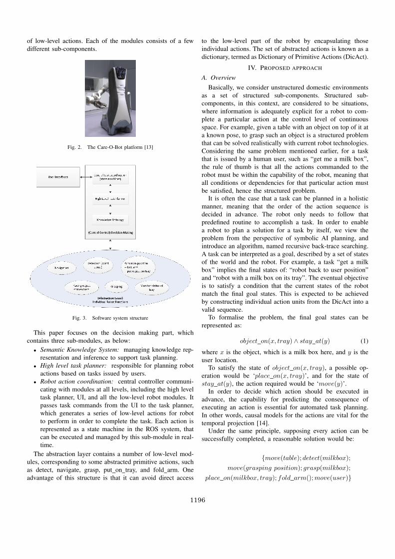
of low-level actions. Each of the modules consists of a fewdifferent sub-components.
Fig. 2. The Care-O-Bot platform [13]
Fig. 3. Software system structure
This paper focuses on the decision making part, whichcontains three sub-modules, as below:
• Semantic Knowledge System: managing knowledge rep-resentation and inference to support task planning.
• High level task planner: responsible for planning robotactions based on tasks issued by users.
• Robot action coordination: central controller communi-cating with modules at all levels, including the high leveltask planner, UI, and all the low-level robot modules. Itpasses task commands from the UI to the task planner,which generates a series of low-level actions for robotto perform in order to complete the task. Each action isrepresented as a state machine in the ROS system, thatcan be executed and managed by this sub-module in real-time.
The abstraction layer contains a number of low-level mod-ules, corresponding to some abstracted primitive actions, suchas detect, navigate, grasp, put on tray, and fold arm. Oneadvantage of this structure is that it can avoid direct access
to the low-level part of the robot by encapsulating thoseindividual actions. The set of abstracted actions is known as adictionary, termed as Dictionary of Primitive Actions (DicAct).
IV. PROPOSED APPROACH
A. OverviewBasically, we consider unstructured domestic environments
as a set of structured sub-components. Structured sub-components, in this context, are considered to be situations,where information is adequately explicit for a robot to com-plete a particular action at the control level of continuousspace. For example, given a table with an object on top of it ata known pose, to grasp such an object is a structured problemthat can be solved realistically with current robot technologies.Considering the same problem mentioned earlier, for a taskthat is issued by a human user, such as “get me a milk box”,the rule of thumb is that all the actions commanded to therobot must be within the capability of the robot, meaning thatall conditions or dependencies for that particular action mustbe satisfied, hence the structured problem.
It is often the case that a task can be planned in a holisticmanner, meaning that the order of the action sequence isdecided in advance. The robot only needs to follow thatpredefined routine to accomplish a task. In order to enablea robot to plan a solution for a task by itself, we view theproblem from the perspective of symbolic AI planning, andintroduce an algorithm, named recursive back-trace searching.A task can be interpreted as a goal, described by a set of statesof the world and the robot. For example, a task “get a milkbox” implies the final states of: “robot back to user position”and “robot with a milk box on its tray”. The eventual objectiveis to satisfy a condition that the current states of the robotmatch the final goal states. This is expected to be achievedby constructing individual action units from the DicAct into avalid sequence.
To formalise the problem, the final goal states can berepresented as:
object on(x, tray) ∧ stay at(y) (1)
where x is the object, which is a milk box here, and y is theuser location.
To satisfy the state of object on(x, tray), a possible op-eration would be ‘place on(x, tray)’, and for the state ofstay at(y), the action required would be ‘move(y)’.
In order to decide which action should be executed inadvance, the capability for predicting the consequence ofexecuting an action is essential for automated task planning.In other words, causal models for the actions are vital for thetemporal projection [14].
Under the same principle, supposing every action can besuccessfully completed, a reasonable solution would be:
{move(table); detect(milkbox);
move(grasping position); grasp(milkbox);
place on(milkbox, tray); fold arm();move(user)}
1196

TABLE IPRE-CONDITIONS AND POST-CONDITIONS OF SOME ACTIONS
Action pre-condition post-conditionmove(x) safe mode() stay at(x)grasp(x) graspable(x) ∧
reachable(x)holding() =x ∧ location(x) =location(gripper)
search(x) stay at(detect pos) location(x) = lplace on(x, y) holding() = x object on(x, y) ∧
holding() = nil
The robot first moves to table, which is the workspace ofmilk box. This can be retrieved by querying the relationshipbetween an object and its possible workspace. This will bediscussed later in section IV-D.
To construct the causal model, we use the STRIPS (StanfordResearch Institute Problem Solver) standard, which is a widelyknown standard for modelling actions in automated planning[5]. It defines a protocol, known as action language, to modelenvironment states and actions. Mathematically, one STRIPSinstance is defined as a quadruple < P,O, I,G >, representingthe conditions, the operators or actions, the initial state, and thegoal state. O is the key item here representing each action. Itis usually divided into two sets of state related to the executionof an action, namely pre-conditions and post-conditions. TableI lists the pre-conditions (affordances) and post-conditions(effects) of some actions.
For example, a grasp(x) action can be represented as (giventhe action is successfully completed):Pre-condition: reachable(x) ∧ holding() = nilPost-condition: holding() = xwhere the predicate reachable indicates that the robot basepose is reachable to the object x.
An action can only be executed when the pre-conditionmeets it corresponding affordances. An affordance can beconsidered as a property of an object, which allows an actionto be performed. For example, the affordance for actionplace on(x, tray) would be:
holding(x) ∧ graspable(x) (2)
where holding(x) represents that object x is held by the robotand graspable(x) depicts object x is graspable. Similarly, for‘move(y)’, the affordance would be
safe mode() (3)
indicating that the robot’s current pose or mode is safe tobe moved. Safety is a major issue with domestic servicerobotics. Therefore we need to define the criteria of safe posesof the Care-O-Bot robot, such as with its arm folded to itsback, or its side. The robot can only navigate when it is insafe mode. ¬safe mode() implies that the robot might becurrently manipulating its arm, or the arm might not be foldedto a safe place.
Assume that the current state of the robot is safe mode()∧on tray() = nil, that it is in a safe mode (condition for
moving its base) and there is no object on its tray. The effector post-condition of action ‘move(y)’ can be depicted as:
post condition(move(y))→ stay at(y) ∧safe mode() ∧ (4)on tray() = nil
If the pre-condition is safe mode() ∧ on tray() = x,the post-condition would be stay at(y) ∧ safe mode() ∧on tray() = x. Both states safe mode() and on tray()remain the same, meaning they are independent from the effectof the action. This is known as the Frame problem, and is usedas the standard in this work. This is an important property todetermine the order of actions. The execution of move(y) can-not satisfy all the goal states on tray(x)∧stay at(y), becauseit requires the pre-condition on tray() = x ∧ x 6= nil beforethe action move(y). The planner should not just considerthose individual goal states, which can be inter-dependent.Instead, the planning process should consider the goal statesas a combination, and the affordance must meet the combinedfinal goal states.
B. Recursive back-trace searching for action planning
The basic idea of the algorithm is very simple. As thename indicates, the algorithm recursively searches for feasiblesolutions to achieve the goal states. The system continuouslychecks the robot’s current state against the goal state. If they donot match, it will look for a solution that can have the expectedconsequence. A solution here is one or more actions, which arethe causally-related actions available in the DicAct. In otherwords, the post-condition of these chosen actions must matchthe required states. If the robot is already at its goal states, itmeans that the task is completed and hence there is no furtheraction to be executed.
The algorithm is described in Algorithm 1.Search(GoalState) (see Algorithm 2) is a function forsearching for an action, whose output can match a particularstate, which is usually a sub-goal state or the final goal state.Here, it only searches for ontologically viable solutions,without considering environmental uncertainties, which aredealt with separately using the so-called mental actionsintroduced later. The function match() could involve a stepof optimal action selection of multiple choices, althoughcurrently it is kept as simple as only one viable action isavailable in DicAct.
This algorithm can eventually find a feasible solution if allmatching ontological structures of post-conditions and pre-conditions are found. Although the planned action sequencehas been decided, lots of states are still uncertain becausenot all post-conditions can be predefined explicitly, especiallythose involving robot perception of the environment. In otherwords, the action sequence is planned based on the T-Box ofthe ontology and world states or spatial information retrievalare more related to the A-Box, the instances of spatial objectsin the semantic map. Thus, the robot only executes one action
1197

at once, and after the execution, corresponding world modelswill be updated based on the result and the action post-condition. The planning will be performed at every step.
Algorithm 1 Pseudo code of recursive back-trace searchGBTSearch(GoalState,RobotState) :if match(GoalState, RobotState) then
return TRUEelseaction← Search(GoalState)if action == null then
return FALSEend ifSub GoalState← pre condition(action)return GBTSearch(Sub GoalState,RobotState)
end if
Algorithm 2 Pseudo code of searching for action unitSearch(Sub GoalState) :for all action in DicAct do
if match(output(action), Sub GoalState) thenreturn action
end ifend for
C. Formalism and ontological representation
To make the above algorithm feasible in practice, theontology for action representation and environment represen-tation must follow a standard protocol. Similar to STRIPS,an action here is defined with four main attributes, which arenamely pre-condition, post-condition, input and result. Figure4 illustrates the basic structure of an action instance in theontology.
There are two additional attributes, input and output,which are used to specify the exact required inputs andpossible outputs. For example, input for move(x) is thecoordinate of the target in the format of 2D pose. The outputwould be the possible results of the action, such as successfulor failed. The output of a successful action indicates that thepost-condition would be stay at(x).
As mentioned, OWL/RDF is employed in this work andwe use Protege [15] to build the ontology by modifying theexisting KnowRob ontology to suit this work. To query andprocess the ontology, Jena 2, Pellet 3, and SPARQL are used tohandle and reason the ontology. Figure 4 shows the structureof class RobotAction. A RobotAction instance is connectedto WorldState with two object properties, requirePreConditionand producePostCondition. Pre-condition and post-conditionare associated with class WorldState, which has a few sub-classes. Conjunction of some WorldState instances form aworld state. ActionInput and ActionOutput are connected to
2http://incubator.apache.org/jena/3http://www.clarkparsia.com/pellet
RobotAction by properties of requireInput and produceOutputrespectively. Figure 5 shows an example of a particular Robo-tAction, MoveAction, which requires input of TargetCoordinateand pre-condition of SafeMode, and produces post-conditionof StayAt.
Fig. 4. RobotAction ontology structure
Fig. 5. MoveAction ontology structure
D. Environment uncertainties and mental actions
The above work has only discussed the action ontology. Asmentioned earlier, another challenge is how to handle planningin highly dynamic environments. In this section, we are mainlyconcerned about how to retrieve spatial information of objects.In other words, it is hoped that the robot will be able toinfer possible locations for a particular action. For example,a ‘search for milk box’ task would require information of theworkspace for a milk box.
Such information retrieval is also referred to as actions,termed mental actions in this paper. There are two types ofmental action here, ontological mental actions and task specificsymbol grounding actions.
• Ontological Mental Action: Information is retrievedbased on only logic rules from the ontology. For example,an instance of class MilkBox can be known to be on atable (e.g. an instance of Table, Table0).
• Symbol Grounding Mental Action: Information is re-trieved by involving symbol grounding calculation. Sym-bol grounding is a key component bridging the symbolicplanning at the abstract level and the actual robot sensingand actuation. An example would be that move(table)represents the action of moving the robot base to ‘near’the object of table. Symbol grounding needs to calculatethe target coordinate, where exactly is ‘near’ the table.
With the current scenario, only three mental actions aredefined:
1198

a) workspace of(x): This action retrieves the spatialinformation of the possible workspace or furniture of objectx. There are three ways of doing this. First, it tries to queryany existing instance of class x. An existing object, suchas milk box, can be defined with a pose or its spatially-related workspace semantically. In our testing semantic map,an instance named MilkBox0 has a property, aboveOf, withan instance of Table, named Table0. The property aboveOf isa sub-property of spatiallyRelated. With the OWL ontology,the furniture workspace can be easily retrieved by SPARQL.Second, it uses the T-Box ontology to retrieve relevant in-formation. For example, milk is perishable, hence is related tofridge. If there is an instance of Fridge, this function will returnthe information of this fridge instance. This part requires thereasoning capability of the Pellet library. The last one is basedon the likelihood estimation of possible locations of object x.Any piece of furniture in the kitchen with a flat top surface canbe a possible workspace. The likelihood estimation is based onthe experience where the object is observed more often, andcan be modelled as p(i) = max(p(0), p(1), . . . , p(n)) where0 ≤ i ≤ n and n is the number of possible workspaces.
b) detection position(workspace, env info): This isa typical symbol grounding approach, which calculates thepossible locations for the robot to view the workspace in orderto locate the target object. The calculation is based on theconfiguration of the robot, the dimension of the workspace,and also the environmental information. The algorithm is notdetailed here now, as it is out of the scope of the paper.
c) grasping position(object info, workspace, env info):Similarly, this is also a symbol grounding method thatcomputes the best pose for the robot base in order to grasp anobject, given that the pose of the object is known in advance.As above, this is determined based on the robot configuration(manipulator reachability), and obstacle information, such asfurniture.
V. EXPERIMENTS AND CASE STUDIES
In this section, a simple proof of concept for the samescenario ‘search for milk’ is demonstrated. An action sequencegenerated based on the idea for two different cases are shownseparately. For illustrative purposes, the execution of robotactions is demonstrated in a simulated environment. The soft-ware is developed in the ROS environment, so that the softwarecan be used with the real robot. The simulation environmentuses a map that is identical to the real test site, named as IPA-kitchen (see figure 7). There are two functional areas, includinga kitchen and a living room. In the kitchen, there is a fridge(labelled Fridge0), a dishwasher (Dishwasher0), a stove top(Stove0), a sink (Sink0), and a oven (Oven0). The living roomcontains a sofa (Sofa0) and a table (Table0).
There is also an instance of Milkbox, named MilkBox0 in thedatabase. It has a property aboveOf in relation to an instanceof DishWasher, named DishWasher0. The property aboveOfis a sub-property of spatiallyRelated.
The following two scenarios describe how the robot behavesin two different situations.
A. Scenario 1
In this case, the environment is exactly the same as rep-resented in the semantic map, where a milk box (Milk-Box0) is on the dishwasher (DishWasher0) in the kitchen, asobject on(MilkBox0, DishWasher0).
For the sake of simplicity, this differs from the originalscenario, which requires the robot to move back to the userafter fetching a milk box. The final goal state here is describedas object on(MilkBox0, tray) only. Based on table I, theprevious step of action would be place on(MilkBox0, tray),which has the post-condition as the goal state. Its pre-conditionrequires the object to be held by its manipulator, represented asholding() = MilkBox0. Similarly, to meet this condition, an-other action with a post-condition of holding() = MilkBox0is thus required. Using the same principle, the action sequencecan be then iteratively created until all conditions are satisfiedfor the current state of the robot to execute the first action.Figure 7 shows some screenshots of the simulation of thisscenario. Figure 6 shows the complete action sequence forthis scenario. The middle box shows all primitive actions forthe robot to execute. The right box shows the states which aredynamic along with the execution of the robot actions. It canbe seen that every two adjacent actions must share a commonstate as the post-condition or effect and pre-condition of theactions respectively.
It can be also seen that the mental actions areneeded for information retrieval when uncertainties ex-ist. Mental actions are mainly used for two purposes:to update the world state and retrieve information aboutthe world state. For example, with the grasping action,grasping pose(pose(MilkBox0)) is used to calculate thebest grasping position for the robot base in order to graspMilkBox0 at a known pose, depicted as pose(MilkBox0).The world state would then be updated as holding() =MilkBox0∧¬object on(MilkBox0, DishWasher0). Simi-larly, other mental actions are required for other correspondingactions or state update.
B. Scenario 2
In this case, the milk box (MilkBox0) is actually located onthe table (Table0), rather than the dishwasher (DishWasher0),as stored in the database. Similar to scenario 1 above, theinitial planned action sequence is identical to scenario 1, as itis believed (‘stored in database’) that the MilkBox0 instanceis located on top of DishWasher0. However, during theexecution, the search or detection will fail because MilkBox0is not located at the place, where the robot believes. The statewill be updated correspondingly that MilkBox0’s location isunknown. In this case, the system is re-planned based on theupdated environment. The object MilkBox0 is known to be noton DishWasher0 (¬object on(MilkBox0, DishWasher0).To further explore the room for possible locations, the mentalaction workspace of(MilkBox) can return a list of possibleworkspaces, including Table0, which has not been explored.It will then follow the same procedure as scenario 1, but witha different workspace only.
1199

Fig. 6. Action ontology structure
C. Discussion, limitations, and future work
The above experiments have shown the feasibility of us-ing knowledge representation for automated task planningby defining every primitive action following a STRIPS-likeprotocol. The advantage of its flexibility is quite obvious inthat the actions can be easily recreated or restructured, andthe corresponding software modules would be highly reusable.On the other hand, apparently, the use of semantic map caneffectively improve the efficiency of searching for a particularobject by limiting the search space using semantic inference.
However, there are some disadvantages or limitations. Itis sensitive to how precisely the action structures have beendefined in the semantic ontology, in terms of pre-condition,post-condition, input and output. The planning can only workby finding the exact matched pre-condition and post-conditionstates. In addition, the current version only relies on theontological structure to search for the action. This is certainlynot enough to handle more complex situations with moreaction units defined in different context.
In this work, the scenarios are still far simpler than realdomestic environments. For simplicity, it is currently assumedthat furniture pieces are always at fixed locations. Of course,this assumption is not an obstacle in proving the idea ofbuilding an ontology for automated task planning. Only theaction sequence would be more complicated as additional stepsof searching for furniture would be required.
Apart from the above limitations, future work would alsoinclude the verification of the generated action sequence.Additional properties should be added for more reliable action
sequence generation, rather than only relying on the ontolog-ical structure.
VI. CONCLUDING REMARKS
This paper has proposed a method for constructing a flexibleand reusable ontology for task planning. This work attemptedto combine semantic knowledge representation with classicalapproaches in AI for task planning. Environment specific infor-mation is handled separately for handling spatial uncertainties.Action sequence generation is based on a recursive back-trace searching method, enabled by the STRIPS-style modelof primitive actions. The method is also validated by a realscenario for service robots ‘search for milk’ using the Care-O-Bot in a simulated environment.
ACKNOWLEDGEMENT
This work was financed by the EU FP7 ICT project “Multi-Role Shadow Robotic System for Independent Living (SRS)”(247772).
REFERENCES
[1] M. Tenorth and M. Beetz, “KnowRob — knowledge processing forautonomous personal robots,” in Proc. IEEE/RSJ Int. Conf. IntelligentRobots and Systems IROS 2009, 2009, pp. 4261–4266.
[2] M. Tenorth, L. Kunze, D. Jain, and M. Beetz, “KnowRob-map -knowledge-linked semantic object maps,” in Proc. 10th IEEE-RAS IntHumanoid Robots (Humanoids) Conf, 2010, pp. 430–435.
[3] C. Galindo, J. Fernandez-Madrigal, J. Gonzalez, and A. Saffiotti, “Robottask planning using semantic maps,” Robotics and Autonomous Systems,vol. 56, no. 11, pp. 955–966, 2008.
[4] R. C. Arkin, Behavior-Based Robotics. A Bradford Book, 1998.[5] R. E. Fikes and N. J. Nilsson, “Strips: A new approach to the application
of theorem proving to problem solving,” Artificial Intelligence, vol. 2,no. 3-4, pp. 189–208, 1971.
1200

[6] E. D. Sacerdott, “Planning in a hierarchy of abstraction spaces,” inProceedings of the 3rd international joint conference on Artificialintelligence. San Francisco, CA, USA: Morgan Kaufmann PublishersInc., 1973, pp. 412–422.
[7] L. P. Kaelbling and T. Lozano-Perez, “Hierarchical task and motionplanning in the now,” in Proc. IEEE Int Robotics and Automation (ICRA)Conf, 2011, pp. 1470–1477.
[8] C. Geib, K. Mourao, R. Petrick, N. Pugeault, M. Steedman, N. Krueger,and F. Woergoetter, “Object action complexes as and interface for plan-ning and robot control,” in Proceedings of the Humanoids Workshop:Towards Cognitive Humanoid Robots, 2006.
[9] E. Erdem, K. Haspalamutgil, C. Palaz, V. Patoglu, and T. Uras, “Combin-ing high-level causal reasoning with low-level geometric reasoning andmotion planning for robotic manipulation,” in Proc. IEEE Int Roboticsand Automation (ICRA) Conf, 2011, pp. 4575–4581.
[10] S. S. Hidayat, B. K. Kim, and K. Ohba, “Learning affordance forsemantic robots using ontology approach,” in Proc. IEEE/RSJ Int. Conf.Intelligent Robots and Systems IROS, 2008, pp. 2630–2636.
[11] A. Preece, M. Gomez, G. d. Mel, W. Vasconcelos, D. Sleeman, S. Colley,and T. L. Porta, “Matching sensors to missions using a knowledge-basedapproach,” in SPIE Defense Transformation and Net-Centric Systems,Orlando, Florida, 2008.
[12] L. Kunze, T. Roehm, and M. Beetz, “Towards semantic robot descriptionlanguages,” in Proc. IEEE Int Robotics and Automation (ICRA) Conf,2011, pp. 5589–5595.
[13] [Online]. Available: http://www.care-o-bot-research.org[14] M. Beetz, Concurrent reactive plans: anticipating and forestalling
execution failures. Berlin, Heidelberg: Springer-Verlag, 2000.[15] H. Knublauch, R. W. Fergerson, N. F. Noy, and M. A. Musen, “The
Protege OWL Plugin: An Open Development Environment for SemanticWeb Applications,” in The Semantic Web ISWC 2004, ser. Lecture Notesin Computer Science, S. . McIlraith, D. Plexousakis, and r. a. n. k. van,Harmelen, Eds. Berlin, Heidelberg: Springer Berlin / Heidelberg, 2004,vol. 3298, ch. 17, pp. 229–243.
(a) At home position
(b) Searching for milkbox
(c) Grasping milkbox
(d) Milkbox on tray
(e) Move to user
(f) Finish
Fig. 7. Simulation of scenario 11201
Powered by TCPDF (www.tcpdf.org)
Evaluation of 3D Feature Descriptors for Classification of SurfaceGeometries in Point Clouds
Georg Arbeiter1, Steffen Fuchs1, Richard Bormann1, Jan Fischer1 and Alexander Verl1
Abstract— This paper investigates existing methods for 3Dpoint feature description with a special emphasis on theirexpressiveness of the local surface geometry. We choose threepromising descriptors, namely Radius-Based Surface Descrip-tor (RSD), Principal Curvatures (PC) and Fast Point FeatureHistograms (FPFH), and present an approach for each ofthem to show how they can be used to classify primitivelocal surfaces such as cylinders, edges or corners in pointclouds. Furthermore these descriptor-classifier combinationshave to hold an in-depth evaluation to show their discriminativepower and robustness in real world scenarios. Our analysisincorporates detailed accuracy measurements on sparse andnoisy point clouds representing typical indoor setups for mobilerobot tasks and considers the resource consumption to assurereal-time processing.
I. INTRODUCTION
Perception of the environment is crucial for the accom-plishment of tasks by mobile service robots. Both for navi-gation and manipulation, a 3D representation of the robot’ssurroundings is inevitable.
Current mobile service robots, such as the Care-O-bot R© 3,are designed to interact in everyday environments. The greatdiversity of such unstructured environments and the objectsin them makes it difficult to provide models of all relevantobjects and teaching every situation will never be achievable.Thereby adding semantic information in a more generic wayto the sensor data can help the robot to perceive the complexworld with more flexibility and handle new and unexpectedsituations more reliably.
With the continuous increase of computational capacitiesresearch areas dealing with 3D cognition problems becomemore and more appealing. Furthermore the introduction ofthe Microsoft Kinect camera, as being the first real time 3Dsensing device in the low-cost section, caused a major boostfor the development of applications using 3D perception.Thus a variety of 3D feature descriptor algorithms haveevolved in the recent past. Promising similar properties andhaving common applications, there is yet no comparativeevaluation of these methods available.
In this paper we investigate existing 3D feature descriptorsthat can be used to classify local surface geometries in pointclouds. These local features use the information provided bya point’s k closest neighbors to represent this point in a morediscriminative geometrical way. Interpreting these estimatedfeature values by applying a specific classifier allows us to
1The authors are with the Institute for Manufacturing Engineeringand Automation, Fraunhofer IPA, 70569 Stuttgart, Germany<first name>.<last name> at ipa.fraunhofer.dewww.ipa.fraunhofer.de
assign a label to each point that defines on which surface typethe point lies. For the purpose of this work we differentiatebetween the following five basic surface types: plane (P),edge (E), corner (Co), cylinder (Cy), sphere (S).
These descriptor-classifier combinations have to holdagainst a series of test scenarios and will be evaluated interms of accuracy and computation time. This evaluationis intended to show what capabilities and limitations eachfeature descriptor has regarding its potential to “classify theworld”. The scenario point clouds are exclusively acquiredfrom PrimeSense cameras. This puts a special requirementon each descriptor to sustain the device’s typical noise andquantization errors [1].
The remainder of the paper is structured as follows:Section II provides an overview of existing descriptors andcurrent related work. Section III explains about the methodsused for feature estimation. The specific approaches to in-terpret these descriptor values are presented in Section IV.In Section V we show the implementation details for ourbenchmark setup. Results are presented and discussed inSection VI.
II. RELATED WORK
In the recent past many feature types for point cloudshave been proposed and most of them addressed problemsof object recognition and point cloud registration. Some ofthem were ported successfully from the 2D domain, such asRIFT [2], others like spin images [3] or curvature maps [4]were adopted from the 3D mesh department.
Another popular family are descriptors belonging to thefeature histograms. Inspired by the work of [5] the PointFeature Histograms (PFH) [6] were deployed for geometricalsurface description and later on refined in terms of compu-tation time under the name Fast Point Feature Histograms(FPFH) [7]. Further modifications exist as Global Fast PointFeature Histograms (GFPFH) [8] and Viewpoint FeatureHistograms (VFH) [9] which put their emphasis on objectrecognition in a more global manner.
Spin Images and 3D Shape Contexts [10] are popular de-scriptors for object recognition tasks. Unique Shape Context[11] presents an improvement of the later one in terms ofaccuracy and reduced memory consumption. However, theyare sensitive to sensor noise and require densely sampleddata [12]. The RIFT descriptor and intensity-domain spinimages [2] only work with intensity information providedfor every point of the point cloud which is the case for mostlaser scanner systems but not for PrimeSense cameras. Alsointensity values are stronger related to the surface texture
2012 IEEE/RSJ International Conference onIntelligent Robots and SystemsOctober 7-12, 2012. Vilamoura, Algarve, Portugal
978-1-4673-1736-8/12/S31.00 ©2012 IEEE 1644
than to the actual geometry, which does not really help toclassify local shapes.
Two approaches relying on surface normal estimationare Principal Curvatures (PC) (provided by [13]) and theRadius-Based Surface Descriptor (RSD) [14]. Both derivelocal surface information from point normals in a localneighborhood. They have a strong potential provided thatthe normal estimation is robust against noise.
[6] and [15] propose two concepts of surface classificationusing PFH and RSD but both of them were tested withlaser scanners only. Besides of those mentioned previouslythe majority of proposals either tackle the less genericproblem of specific object recognition and fitting using largepredefined data sets. Or they discuss the methods that focuson problems involving simple plane segmentation (e.g. [16])while ignoring other shape types.
In the majority of the work mentioned, a comparativeevaluation to other feature types is not performed. Most ofthe times, the descriptive power of the features is only shownin sample images instead of quantitative results and the sceneselection is not sufficient both in variety and quantity.
In contrast, the work presented here intends to evaluatecertain feature descriptors against each other. Key character-istics of the descriptors have to be (1) real-time processing,(2) robustness against noise, (3) no use of intensity data (asthe data comes from a PrimeSense device), (4) the ability todescribe local surface geometries and (5) an efficient open-source implementation. Regarding these prerequisites, weselect RSD, FPFH and PC for an in-depth evaluation.
III. FEATURE DESCRIPTORS
The following section gives an overview of the investi-gated feature descriptors and presents a short explanationof their principals and characteristics. A prerequisite forall feature estimation algorithms is a point cloud P ={p1, p2, ..., pn}, with n feature points pi where each featurepoint is a subset of m feature values pi = {f1, f2, ..., fm}.In our case every feature point at least consists of the valuespi = {pi,ni}, where
pi = [xi, yi, zi]T (1)
represents the 3D position vector of pi and
ni = [nxi, nyi, nzi]T (2)
the local surface normal vector of pi. Since examining thebest normal estimation algorithm is not part of this work,though a good representation of the surface normals is keyto all algorithm investigated here. Therefore we went withthe method suggested by [17] which performs a PrincipalComponent Analysis on surrounding points, where the direc-tion of the third component represents the surface normal.In the following the k surrounding points, also called localneighborhood, of a point pi are referred to as a subset Pk
of points pj , (j ∈ {1...k}), where ‖pi − pj‖2 ≤ r with‖ · ‖2 being the Euclidean distance and r a defined sphereradius. Collecting this set of points is an essential part ofthe algorithms described here and is carried out by using
the same implementation of a fixed radius search for everydescriptor.
After running the descriptor algorithm, each point pi ofthe point cloud P is extended to pi = {pi,ni,di}, wheredi represents the estimated values of the used descriptor.
A. Radius-based Surface Descriptor
RSD as proposed in [14] describes the geometry of a pointpi by estimating the radius of the fitting curves to its localneighborhood Pk. The feature values of each point consistof a maximum and minimum curvature radius taken fromthe distribution of normal angles by distance.
The problem of finding rmax and rmin can be solved byassuming that the relation between the distance d of twopoints and the angle α between the points’ normals
d(α) =√
2r√
1− cosα (3)
can be simplified for α ∈ [0, π/2] as
d(α) = rα (4)
The estimated values at each point pi finally are presentedas di = [rmax, rmin].
B. Principal Curvatures
This feature describes the point’s local surface geometryas a measure of its maximum and minimum curvature alongwith a normalized vector indicating the first of the principaldirections. This approach is very similar to the one RSD isbased on and makes both descriptors closely related in termsof how they describe one point’s neighborhood. However theimplementation of the PC estimation algorithm [13] differssomewhat from RSD.
All normals nj of the neighborhood Pk are projected onthe tangent plane of the surface defined by the normal nq atthe query point pq
mj = (I− nq · nTq ) · nj (5)
with I being a 3× 3 identity matrix. Computing the covari-ance matrix A ∈ R3×3 from all projections mj
A =1
k
k∑j=1
(mj − m)(mj − m)T (6)
where m being the mean vector of all mj and solving
A · xl = λl · xl (7)
to find the non-zero eigenvectors xl and their eigenvaluesλl, with l ∈ {1, 2, 3}. If 0 ≤ λ1 ≤ λ2 ≤ λ3 then λ3corresponds to the maximum curvature cmax and λ2 to theminimum curvature cmin. Along with these values, the PCdescriptor also provides the normalized eigenvector x3 of themaximum curvature which results in the final representationof each point pi = {pi,ni,di} with di =
[cmax, cmin,x
T3
].
1645
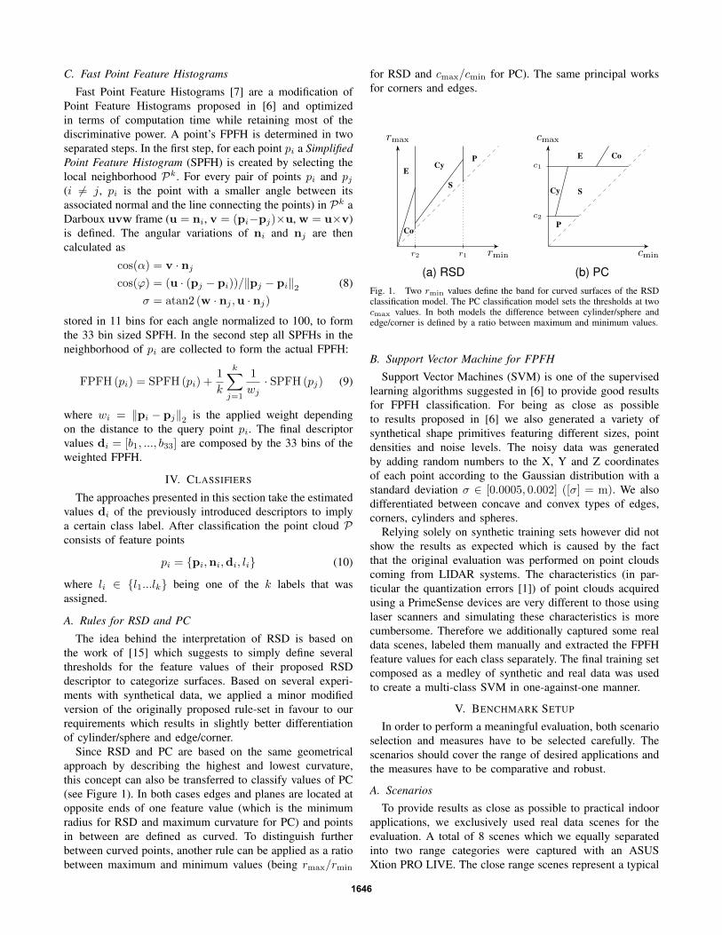
C. Fast Point Feature Histograms
Fast Point Feature Histograms [7] are a modification ofPoint Feature Histograms proposed in [6] and optimizedin terms of computation time while retaining most of thediscriminative power. A point’s FPFH is determined in twoseparated steps. In the first step, for each point pi a SimplifiedPoint Feature Histogram (SPFH) is created by selecting thelocal neighborhood Pk. For every pair of points pi and pj(i 6= j, pi is the point with a smaller angle between itsassociated normal and the line connecting the points) in Pk aDarboux uvw frame (u = ni, v = (pi−pj)×u, w = u×v)is defined. The angular variations of ni and nj are thencalculated as
cos(α) = v · nj
cos(ϕ) = (u · (pj − pi))/‖pj − pi‖2σ = atan2 (w · nj ,u · nj)
(8)
stored in 11 bins for each angle normalized to 100, to formthe 33 bin sized SPFH. In the second step all SPFHs in theneighborhood of pi are collected to form the actual FPFH:
FPFH (pi) = SPFH (pi) +1
k
k∑j=1
1
wj· SPFH (pj) (9)
where wi = ‖pi − pj‖2 is the applied weight dependingon the distance to the query point pi. The final descriptorvalues di = [b1, ..., b33] are composed by the 33 bins of theweighted FPFH.
IV. CLASSIFIERS
The approaches presented in this section take the estimatedvalues di of the previously introduced descriptors to implya certain class label. After classification the point cloud Pconsists of feature points
pi = {pi,ni,di, li} (10)
where li ∈ {l1...lk} being one of the k labels that wasassigned.
A. Rules for RSD and PC
The idea behind the interpretation of RSD is based onthe work of [15] which suggests to simply define severalthresholds for the feature values of their proposed RSDdescriptor to categorize surfaces. Based on several experi-ments with synthetical data, we applied a minor modifiedversion of the originally proposed rule-set in favour to ourrequirements which results in slightly better differentiationof cylinder/sphere and edge/corner.
Since RSD and PC are based on the same geometricalapproach by describing the highest and lowest curvature,this concept can also be transferred to classify values of PC(see Figure 1). In both cases edges and planes are located atopposite ends of one feature value (which is the minimumradius for RSD and maximum curvature for PC) and pointsin between are defined as curved. To distinguish furtherbetween curved points, another rule can be applied as a ratiobetween maximum and minimum values (being rmax/rmin
for RSD and cmax/cmin for PC). The same principal worksfor corners and edges.
rmax
rmin
PE
Co
Cy
S
r1r2
(a) RSD
cmax
cmin
P
E Co
Cy S
c2
c1
(b) PCFig. 1. Two rmin values define the band for curved surfaces of the RSDclassification model. The PC classification model sets the thresholds at twocmax values. In both models the difference between cylinder/sphere andedge/corner is defined by a ratio between maximum and minimum values.
B. Support Vector Machine for FPFH
Support Vector Machines (SVM) is one of the supervisedlearning algorithms suggested in [6] to provide good resultsfor FPFH classification. For being as close as possibleto results proposed in [6] we also generated a variety ofsynthetical shape primitives featuring different sizes, pointdensities and noise levels. The noisy data was generatedby adding random numbers to the X, Y and Z coordinatesof each point according to the Gaussian distribution with astandard deviation σ ∈ [0.0005, 0.002] ([σ] = m). We alsodifferentiated between concave and convex types of edges,corners, cylinders and spheres.
Relying solely on synthetic training sets however did notshow the results as expected which is caused by the factthat the original evaluation was performed on point cloudscoming from LIDAR systems. The characteristics (in par-ticular the quantization errors [1]) of point clouds acquiredusing a PrimeSense devices are very different to those usinglaser scanners and simulating these characteristics is morecumbersome. Therefore we additionally captured some realdata scenes, labeled them manually and extracted the FPFHfeature values for each class separately. The final training setcomposed as a medley of synthetic and real data was usedto create a multi-class SVM in one-against-one manner.
V. BENCHMARK SETUP
In order to perform a meaningful evaluation, both scenarioselection and measures have to be selected carefully. Thescenarios should cover the range of desired applications andthe measures have to be comparative and robust.
A. Scenarios
To provide results as close as possible to practical indoorapplications, we exclusively used real data scenes for theevaluation. A total of 8 scenes which we equally separatedinto two range categories were captured with an ASUSXtion PRO LIVE. The close range scenes represent a typical
1646

Fig. 2. RGB images of the far range scenes. t.l.: kitchen far, t.r.: table far,b.l.: office far, b.r.:cupboard far
setup for object identification and manipulation tasks andare evaluated up to a distance of 1.8 m. The far rangescenes (see Figure 2) feature situations where an overviewof the environment is needed, for example to find a certaindrawer in the kitchen. Due to the quadratically increasingquanization error of the PrimeSense cameras, we restrictedthe distance to 3.0 m since everything beyond does notprovide any useful information.
To provide the ground truth for every scene, we madeuse of the fact that PrimeSense cameras produce their pointclouds organized. This allowed us to simply import depthand registered RGB images using a drawing program suchas GIMP and colorize each pixel manually. Each class wasrepresented by a particular RGB color code and then mappedback to point cloud1.
B. Measuring Classification Accuracy
For classification tasks, the outcome of a classifier iscommonly measured by comparing the expectations withthe predicted results. For multi-class evaluation problems atypical representation is the confusion matrix A, with Aij
for i, j ∈ {l1...lk} where k is the total number of labels andAij is the number of times a data point of the true label liwas predicted as the label lj . In order to summarize eachscene and to allow an easy comparison among them, wepresent our results using the following four measures. Themicro-average results
Rmic = Pmic = Fmic =
∑ki Aii∑k
i
∑kj Aij
=
∑ki tpi∑k
i (tpi + fni)(11)
are the same for recall Rmic, precision Pmic and F-measureFmic and give the fraction of points predicted correctly tothe total number of data points in the scene. Since our testscenarios represent typical indoor setups where the classesare not evenly balanced and the majority of points are located
1The data set is available athttp://www.care-o-bot-research.org/contributing/data-sets
on planes (here: 75 % - 95 %), this measurement easilydistorts the results to advantage for classifiers strong withplanes. Therefore we also provide the three macro-averagedvalues for recall
Rmac =1
k
k∑i
Aii∑kj Aij
=1
k
k∑i
tpitpi + fni
(12)
for precision
Pmac =1
k
k∑i
Aii∑kj Aji
=1
k
k∑i
tpitpi + fpi
(13)
and the F-measure
Fmac =(1 + β2
)· Pmac ·Rmac
(β2 · Pmac) +Rmac(14)
with β = 1 as the harmonic mean of both. These valuesput an even weight on each class and give a more balancedresult.
In addition to the investigation of all five classes wealso examine the use case at every scene where only thediscrimination of planes and edges from more complexshapes is required. For this purpose we consider edges andcorners as being part of the same class (referred to as edges)as well as spheres and cylinders (referred to as curved) whichreduces the evaluation problem to three classes.
C. Implementation Details
All algorthims were implemented in C++ and investigatedon an Intel Core i7-2600 CPU with 16 GB RAM, runningUbuntu 10.10 64 bit. Normal and feature estimation algo-rithms as well as Moving Least Squares smoothing wereprovided by PCL2 and OpenCV library3 was used to providethe implementation of the SVM.
VI. RESULTS AND DISCUSSION
A. Computation Time
To investigate the computational complexity of each de-scriptor we measured the running time the estimation algo-rithms take to compute an entire point cloud consisting of232,412 points depending on their local neighborhood radius.Since these measurements depend very much on the systemthey are running on, Figure 3 presents the measurements inpercentage relative to PC as it turns out to be the fastest.In average RSD needs about 13 % and FPFH about 157 %longer than PC.
B. Accuracy
The outcome of each algorithm heavily depends on thecorrect adjustment of the configuration parameters for eachindividual scene. Whereas the parameters suggested in [6]work well for more accurate devices such as laser scanners,we could not obtain satisfying results with these for oursetup and needed a different configuration. While smallnormal/feature radii tend to capture many details of the
2http://pointclouds.org/3http://opencv.willowgarage.com/
1647
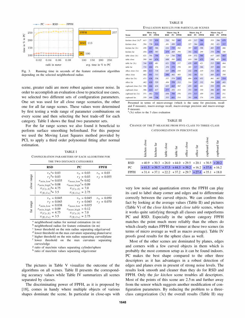
0.02 0.04 0.06 0.08
100
150
200
250
radii in meter
time
in%
toPC
PC RSD FPFH
100 150 200 250
PC
RSD
FPFH
100
113
257
avg. time in % to PC
Fig. 3. Running time in seconds of the feature estimation algorithmdepending on the selected neighborhood radius
scene, greater radii are more robust against sensor noise. Inorder to accomplish an evaluation close to practical use cases,we selected two different sets of configuration parameters.One set was used for all close range scenarios, the otherone for all far range scenes. These values were determinedby first testing a wide range of parameter combinations onevery scene and then selecting the best trade-off for eachcategory. Table I shows the final two parameter sets.
For the far range scenes we also found it beneficial toperform surface smoothing beforehand. For this purposewe used the Moving Least Squares method provided byPCL to apply a third order polynomial fitting after normalestimation.
TABLE ICONFIGURATION PARAMETERS OF EACH ALGORITHM FOR
THE TWO DISTANCE CATEGORIES
RSD PC FPFH
clos
era
nge rna= 0.03 rn = 0.03 rn = 0.03
rfb= 0.03 rf = 0.03 rf = 0.055
rmin,lowc= 0.035 cmax,low
d= 0.02rmin,high
e= 0.08 cmax,highf = 0.09
x(Cy,S)g= 4.75 x(Cy,S) = 7.0
x(E,Co)h= 3.5 x(E,Co) = 2.75
far
rang
e
rn = 0.045 rn = 0.045 rn = 0.050rf = 0.045 rf = 0.045 rf = 0.070
rmin,low = 0.038 cmax,low = 0.035rmin,high = 0.09 cmax,high = 0.12x(Cy,S) = 4.75 x(Cy,S) = 7.0x(E,Co) = 3.5 x(E,Co) = 2.75
a neighborhood radius for normal estimation (in m)b neighborhood radius for feature estimation (in m)c lower threshold on the min radius separating edge/curvedd lower threshold on the max curvature separating plane/curvee higher threshold on the min radius separating curved/planef lower threshold on the max curvature separating
curves/edgeg ratio of max/min values separating cylinder/sphereh ratio of max/min values separating edge/corner
The pictures in Table V visualize the outcome of thealgorithms on all scenes. Table II presents the correspond-ing accuracy values while Table IV summarizes all scenesseparated by classes.
The discriminating power of FPFH, as it is proposed by[18], comes in handy where multiple objects of variousshapes dominate the scene. In particular in close-ups with
TABLE IIEVALUATION RESULTS FOR PARTICULAR SCENES
Micro Avg. Macro Avg. R Macro Avg. P Macro Avg. FScene RSD PC FPFH RSD PC FPFH RSD PC FPFH RSD PC FPFH
kitchen close (3c)a .613 .757 .830 .703 .702 .809 .455 .517 .586 .553 .596 .679
kitchen close .594 .738 .816 .491 .499 .615 .327 .364 .446 .392 .421 .517
kitchen far (3c) .458 .667 .586 .616 .735 .562 .397 .443 .398 .483 .553 .466
kitchen far .454 .659 .583 .479 .469 .394 .302 .342 .299 .370 .396 .340
table close (3c) .621 .701 .704 .723 .744 .764 .539 .572 .586 .617 .647 .663
table close .590 .661 .676 .608 .595 .632 .410 .389 .475 .490 .471 .543
table far (3c) .744 .819 .481 .621 .726 .517 .439 .495 .421 .515 .589 .464
table far .734 .804 .476 .478 .570 .378 .285 .317 .306 .357 .408 .338
office close (3c) .686 .813 .718 .645 .696 .519 .442 .498 .419 .524 .581 .464
office close .682 .801 .713 .496 .462 .403 .342 .381 .322 .405 .417 .358
office far (3c) .471 .636 .536 .537 .574 .635 .404 .439 .432 .461 .497 .514
office far .462 .628 .529 .494 .558 .513 .314 .347 .332 .384 .428 .403
cupboard close (3c) .598 .666 .634 .625 .665 .567 .459 .482 .441 .529 .559 .496
cupboard close .586 .643 .617 .477 .452 .414 .353 .369 .330 .406 .407 .368
cupboard far (3c) .571 .682 .721 .658 .706 .576 .473 .517 .459 .551 .597 .511
cupboard far .559 .668 .708 .553 .601 .514 .391 .448 .374 .458 .514 .433
Presented in terms of micro-average (which is the same for precision, recalland F-measure), macro-average recall, macro-average precision and macro-averageF-measure.a (3c) refers to the 3 class evaluation
TABLE IIICHANGE OF THE F-MEASURE FROM FIVE-CLASS TO THREE-CLASS
CATEGORIZATION IN PERCENTAGE
kitc
hen
clos
e
kitc
hen
far
tabl
ecl
ose
tabl
efa
r
offic
ecl
ose
offic
efa
r
cupb
oard
clos
e
cupb
oard
far
RSD + 40.9 + 30.3 + 26.0 + 44.0 + 29.5 + 20.1 + 30.5 + 20.2PC + 41.5 + 39.7 + 37.5 + 44.3 + 39.2 + 16.2 + 37.6 + 16.2FPFH + 31.4 + 37.1 + 22.2 + 37.2 + 29.7 + 27.4 + 35.1 + 18.0
very low noise and quantization errors the FPFH can playits card to label sharp corner and edges and to differentiatecorrectly between the curved objects. We can confirm thisfact by looking at the average values (Table II) and pictures(Table V) of the close kitchen and close table scenes, whereit works quite satisfying through all classes and outperformsPC and RSD. Especially in the sphere category FPFHmatches the point much more reliably than the others dowhich clearly makes FPFH the winner at these two scenes (interms of micro average as well as macro average). Table IVproofs good results for the sphere class as well.
Most of the other scenes are dominated by planes, edgesand corners with a few curved objects in them which isprobably the most common setup as it can be found indoors.PC makes the best shape compared to the other threedescriptors as it has advantages in a robust detection ofedges and planes even in present of strong noise levels. Theresults look smooth and cleaner than they do for RSD andFPFH. Only the far kitchen scene troubles all descriptors.Most of the points of this scene are 2.5 m and further awayfrom the sensor which suggests another modification of con-figuration parameters. By reducing the problem to a three-class categorization (3c) the overall results (Table II) stay
1648

almost the same while naturally the absolute results improvefor every algorithm. Table III shows these improvementsof the F-measure relative to the results of the five-classcategorization for all scenes. One can easily see that PC isthe candidate with highest benefit for this case in most of thescenes which again proofs its strength for planes and edges.
The close relation of RSD and PC can be found in manyof the test scenarios. Both have the characteristic to labelpoints close to an edge as cylinders and have trouble tolabel curved objects correctly. However, RSD seems to bemore affected by noisy data than PC, especially on planes.According to the accuracy values in Table II RSD placessecond in most of scenes where PC performs best.
TABLE IVSHOWS THE ACCURACY RESULTS PER CLASS OVER ALL EVALUATED
SCENES WITH A TOTAL OF ABOUT 1.7 MIO. POINTS.
Precision Recall F-measureClass RSD PC FPFH RSD PC FPFH RSD PC FPFH
Plane .979 .973 .964 .578 .722 .650 .727 .829 .777
Edge .248 .356 .275 .734 .686 .747 .371 .469 .402
Sphere .086 .057 .335 .340 .416 .648 .137 .100 .441
Cylinder .072 .089 .056 .436 .282 .292 .123 .135 .093
Corner .080 .123 .091 .325 .462 .318 .128 .194 .141
Edge+Corner .263 .367 .293 .791 .734 .804 .395 .489 .429
Curved .099 .135 .115 .551 .569 .508 .168 .218 .188
Along with the performance in accuracy and computationtime another important matter is the flexibility. RSD and PCboth are easy to configure and it is very straight forward toadjust them on scenes with different focus. FPFH howeveralways requires the whole process of acquiring and labellingsample data to create a trained model which is cumbersome.
While the results might look satisfying at first, non ofthe algorithms can actually hold up to the requirementsof a practical application using point clouds acquired fromPrimeSense cameras. At least not in the current state the clas-sification is implemented. We identified the major problemto be the liability to the varying quality of the point clouds.Since the quality rapidly decreases for further distances, eachalgorithm has to be readjusted to compensate rising error.
VII. CONCLUSION
In this paper, we presented an in-depth evaluation offeature point descriptors on a variety of real-world scenarios.Both computation time and geometric surface classificationaccuracy have been measured and compared.
FPFH certainly has the potential to precisely classifycomplex shapes. Our experiments however showed that ithas particular trouble dealing with the typical characteristicsof PrimeSense cameras and to compensate that, exhaustiveadjustments and training is required. RSD and PC both showvery similar habits. However PC turns out to be more robustagainst sensor noise and classifies almost every scene muchsmoother than RSD does. In particular for the plane-edge-curved categorization tasks PC cuts a fine figure as long asit is restricted to an acceptable range.
VIII. ACKNOWLEDGEMENTS
This research was financed by the research program ”Ef-fiziente Produktion durch IKT” of the Baden-WurttembergStiftung, project ”ATLAS”.
REFERENCES
[1] K. Khoshelham, “Accuracy analysis of kinect depth data,” in ISPRSworkshop laser scanning 2011, D. Lichti and A. Habib, Eds. Inter-national Society for Photogrammetry and Remote Sensing (ISPRS),August 2011, p. 6.
[2] S. Lazebnik, C. Schmid, and J. Ponce, “A sparse texture representationusing local affine regions,” Pattern Analysis and Machine Intelligence,IEEE Transactions on, vol. 27, no. 8, pp. 1265 –1278, aug. 2005.
[3] A. Johnson and M. Hebert, “Using spin images for efficient objectrecognition in cluttered 3d scenes,” Pattern Analysis and MachineIntelligence, IEEE Transactions on, vol. 21, no. 5, pp. 433 –449, may1999.
[4] T. Gatzke, C. Grimm, M. Garland, and S. Zelinka, “Curvature mapsfor local shape comparison,” in Shape Modeling and Applications,2005 International Conference, june 2005, pp. 244 – 253.
[5] E. Wahl, U. Hillenbrand, and G. Hirzinger, “Surflet-pair-relation his-tograms: a statistical 3d-shape representation for rapid classification,”in 3-D Digital Imaging and Modeling, 2003. 3DIM 2003. Proceedings.Fourth International Conference on, oct. 2003, pp. 474 –481.
[6] R. Rusu, Z. Marton, N. Blodow, and M. Beetz, “Learning informativepoint classes for the acquisition of object model maps,” in Control,Automation, Robotics and Vision, 2008. ICARCV 2008. 10th Interna-tional Conference on, dec. 2008, pp. 643 –650.
[7] R. B. Rusu, N. Blodow, and M. Beetz, “Fast point feature histograms(fpfh) for 3d registration,” in Robotics and Automation, 2009. ICRA’09. IEEE International Conference on, may 2009, pp. 3212 –3217.
[8] R. Rusu, A. Holzbach, M. Beetz, and G. Bradski, “Detecting andsegmenting objects for mobile manipulation,” in Computer VisionWorkshops (ICCV Workshops), 2009 IEEE 12th International Con-ference on, 27 2009-oct. 4 2009, pp. 47 –54.
[9] R. Rusu, G. Bradski, R. Thibaux, and J. Hsu, “Fast 3d recognitionand pose using the viewpoint feature histogram,” in Intelligent Robotsand Systems (IROS), 2010 IEEE/RSJ International Conference on, oct.2010, pp. 2155 –2162.
[10] M. Kortgen, G. J. Park, M. Novotni, and R. Klein, “3d shape matchingwith 3d shape contexts,” in The 7th Central European Seminar onComputer Graphics, Apr. 2003.
[11] F. Tombari, S. Salti, and L. Di Stefano, “Unique shape context for 3ddata description,” in Proceedings of the ACM workshop on 3D objectretrieval, ser. 3DOR ’10. New York, NY, USA: ACM, 2010, pp. 57–62. [Online]. Available: http://doi.acm.org/10.1145/1877808.1877821
[12] A. D. Bimbo and P. Pala, “Content-based retrieval of 3dmodels,” ACM Trans. Multimedia Comput. Commun. Appl.,vol. 2, no. 1, pp. 20–43, Feb. 2006. [Online]. Available:http://doi.acm.org/10.1145/1126004.1126006
[13] R. B. Rusu and S. Cousins, “3D is here: Point Cloud Library (PCL),” inIEEE International Conference on Robotics and Automation (ICRA),Shanghai, China, May 9-13 2011.
[14] Z.-C. Marton, D. Pangercic, N. Blodow, J. Kleinehellefort, andM. Beetz, “General 3d modelling of novel objects from a single view,”2010.
[15] Z.-C. Marton, D. Pangercic, R. Rusu, A. Holzbach, and M. Beetz,“Hierarchical object geometric categorization and appearance classifi-cation for mobile manipulation,” in Humanoid Robots (Humanoids),2010 10th IEEE-RAS International Conference on, dec. 2010, pp. 365–370.
[16] F. Schindler, W. Worstner, and J.-M. Frahm, “Classification andreconstruction of surfaces from point clouds of man-made objects,”in Computer Vision Workshops (ICCV Workshops), 2011 IEEE Inter-national Conference on, nov. 2011, pp. 257 –263.
[17] K. Klasing, D. Althoff, D. Wollherr, and M. Buss, “Comparison ofsurface normal estimation methods for range sensing applications,”in Robotics and Automation, 2009. ICRA ’09. IEEE InternationalConference on, may 2009, pp. 3206 –3211.
[18] R. Rusu, A. Holzbach, N. Blodow, and M. Beetz, “Fast geometricpoint labeling using conditional random fields,” in Intelligent Robotsand Systems, 2009. IROS 2009. IEEE/RSJ International Conferenceon, oct. 2009, pp. 7 –12.
1649
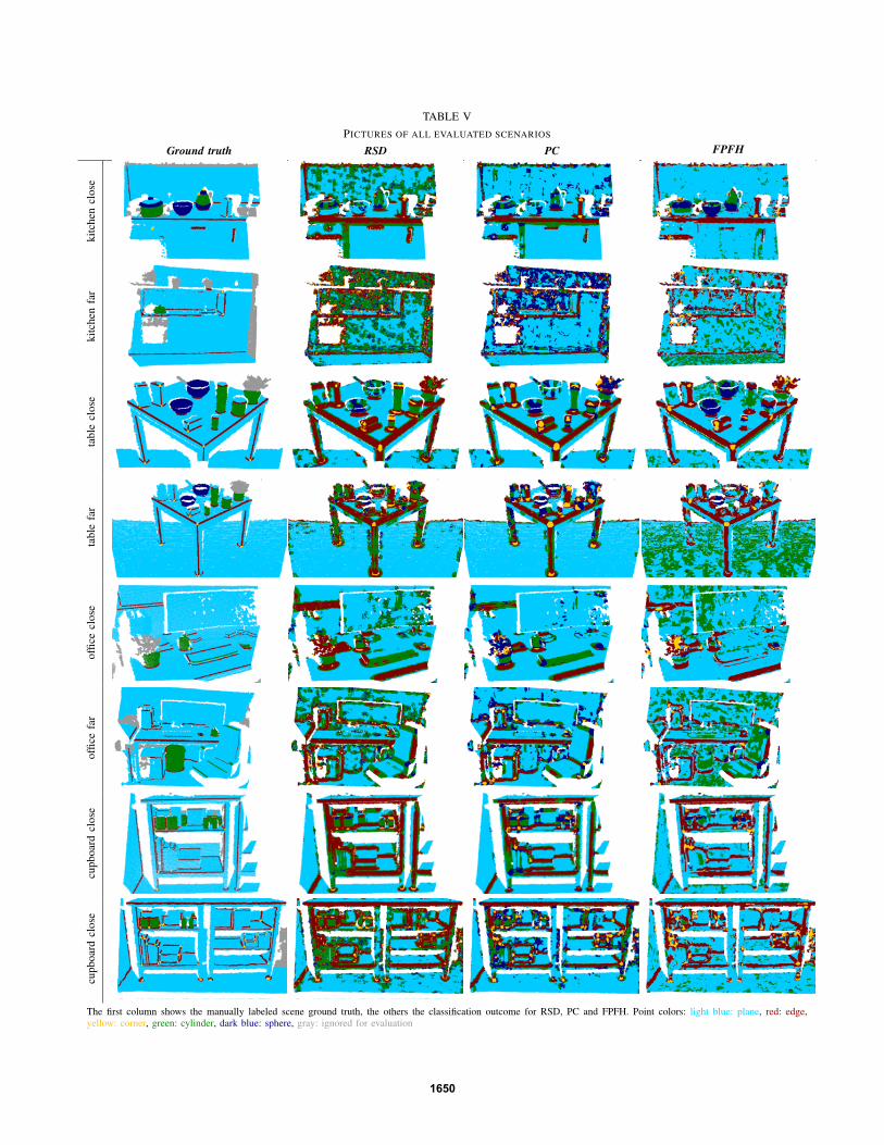
TABLE VPICTURES OF ALL EVALUATED SCENARIOS
Ground truth RSD PC FPFH
kitc
hen
clos
eki
tche
nfa
rta
ble
clos
eta
ble
far
offic
ecl
ose
offic
efa
rcu
pboa
rdcl
ose
cupb
oard
clos
e
The first column shows the manually labeled scene ground truth, the others the classification outcome for RSD, PC and FPFH. Point colors: light blue: plane, red: edge,yellow: corner, green: cylinder, dark blue: sphere, gray: ignored for evaluation
1650
978-1-4673-0311-8/12/$31.00 ©2012 IEEE
Challenges for Service Robots Operating in Non-Industrial Environments
Anthony J. Soroka, Renxi Qiu, Alexandre Noyvirt, Ze Ji Cardiff School of Engineering,
Cardiff University Cardiff, UK
{SorokaAJ, QiuR, NoyvirtA, JiZ1}@cardiff.ac.uk
Abstract— The concept of service robotics has grown considerably over the past two decades with many robots being used in non-industrial environments such homes, hospitals and airports. Many of these environments were never designed to have mobile service robots deployed within them. This paper describes some of the challenges that are faced and need to be overcome in order for robots to successfully work in non-industrial environments (specifically homes and hospitals). These include the problems caused by an environment not having been designed to be robot-friendly, the unstructured nature of the environment and finally the challenges presented by certain user populations who may have difficulties interacting with a robot.
Keywords— service robotics, mobile robots, domestic, hospital, robots, human robot interaction
I. INTRODUCTION The deployment of mobile robots within non-industrial
environments presents the system developers with a new set of challenges. Unlike an industrial unit that would often be designed to include facilities such as automatic guided vehicles (AGVs) a non-industrial environment would require the mobile robot to be designed around an existing environment. Even in industrial situations where robotic facilities are being installed retrospectively it is possible to produce a totally bespoke solution, something that is not feasible within domestic environments for example.
Because of the heterogeneous nature of non-industrial environments such as homes, care-homes and hospitals and their unstructured nature there is no one typical environment that can be used as a starting point. As part of the EU funded IWARD (Intelligent robot swarm for attendance, recognition, cleaning and delivery) [1] and SRS (Multi-role shadow robotic system for independent living) robotics project [2] non-industrial environments were examined with the aim of deploying mobile service robots.
The following sections analyze and summarize the environments that are typically found in non-domestic environments such as homes, care-homes and hospitals. In addition to the general ‘built-environment’ issues the special requirements of people who don’t fall into the generic category of ‘fit and healthy adults’ will be described.
II. SERVICE ROBOTICS The notion of "service robotics" was comparatively
unknown prior to the publication in 1989 of Joseph Engelberger’s book "Robotics in Service"[3]. In this publication Engelberger identified more than 15 different application areas which, based upon his assessment, lend themselves to automation through the application of robotics technology, these include: medical robotics; health care and rehabilitation; commercial cleaning; household tasks; fast food service; farming; gasoline station attendant; surveillance; aiding the handicapped and the elderly.
According to the “World Robotics 2008” [4] document produced by the IFR (International Federation of Robotics) Statistical Department at the end of 2007 there were around one million industrial robots and 5.5 million service robot worldwide operating in factories and in private houses. Within this figure of 5.5 million, there were about 3.4 million units sold as the domestic robots and 2.0 million units sold as entertainment robots. This shows that industry, where robots were originally developed as tools for automation is no longer the largest market (by volume) of robotics technologies. However, it should be noted that many of these domestic service robots maybe significantly less complex than an industrial robot.
The application of robotics within the domestic environment started with fixed workstations providing assistance in manipulation and communication tasks [5], manipulators suitable for wheelchairs [6], and finally autonomous/semi-autonomous mobile robot assistants (either equipped with or without manipulators) were introduced.
Service robots can be clustered into three typical groups: Small (Low-cost) mobile Robots that are not equipped with a manipulator [7][8]; Large mobile Robots without manipulators[9][10]; Large mobile Robots that are fitted with manipulators [11][12]. Service robots of varying complexity can be found in domains as diverse as child-care [13], toys [14], vacuum cleaning [15], lawn-mowing [10], surveillance and guarding [16], hospital assistance [17] and domestic assistance [18].
III. CHARACTERISTICS OF ENVIRONMENT Within a non-industrial environment a mobile robot is
likely to encounter numerous challenges that present varying
978-1-4673-0311-8/12/$31.00 ©2012 IEEE 1152

degrees of difficulty. An important consideration is that the architects of the buildings are likely to have given scant consideration to the deployment of robots. The construction of a domestic property maybe such that it is difficult to make adaptations to the building to facilitate the use of a robot.
This section details the environmental features of a non-industrial environment that may cause problems for a mobile robot.
A. Doors Doors are used in various locations within a home, care-
home, hospital or public buildings such as an airport. This includes entrances to buildings, rooms, doors that separate different areas and fire doors within corridors. Not only is there a high degree of heterogeneity in the types of door available (push-pull, slide, automatic, glass, solid wood, plastic etc.) there may also several types used within a building. As such doors present one of the single most difficult challenges to overcome within a non-industrial, non purpose-built environment.
A survey of various publically accessed sites such as educational establishments and hospitals was conducted as part of the IWARD project. This study has shown that it is in fact not uncommon for fire doors to be held open by means of an electro-magnetic device that causes the door to close when fire is detected, examples of which are shown in Figure 1. This simplifies the issue of access for robots, it is however necessary for the localization system to be aware that a door may be present and that it might be shut.
However, it should be born in mind that the vast majority of doors within any environment are non-‘communal’ i.e. they are doors for rooms, offices, departments, consulting rooms etc as opposed to communal doors for areas such as wards and corridors (so are unlikely to be held open).
Figure 1. Fire and automatic doors in a hospital
Hospitals, shopping centers and offices will often also have fitted automatic doors to assist disabled or infirm people whilst moving around the buildings. This is likely to increase as legislation within Europe and other countries requires improved access for the disabled. Therefore any robot would need to have a system that could active such automatic doors.
Some systems such as those based on a pressure pad (that would open for a child) would be trivial for most mobile robot platforms to deal with. PIR controlled systems (if not triggered
by a large robot) could be adapted to incorporate some form of remote control by the robot. Irrespective of the automatic system used it would be possible (and comparatively trivial) to devise a work-around.
The home environment (as well as most public buildings) will have a number of manual doors, ranging from two-way doors that can either be pulled or pushed open, to conventional doors all the way to sliding door. All of which have a variety of handles and opening mechanisms. This non-uniformity presents a significant issue for robots that perform door opening. However, it should be noted that many systems have been developed that enable door opening, ranging from automatic door openers (such as automatic door openers manufactured by Abloy [19]) to robot manipulators [20].
The opening of doors by a robot could also present a safety hazard. This is because conventional robot arms and mobile bases would typically be programmed to move to a certain position with a certain force. This force must be enough to open the door taking into account the weight of the door (solid fire doors weight more than hollow doors) and resistance to movement (door closers that are fitted to fire doors, sticking of the door and friction caused by intumescent strips in fire doors). Therefore any door opening system has to have a cut—off device that stops the opening process should an unexpected situation arise. This can range from a person being stood behind the door that is being pushed open or a door having been locked.
As well as robots opening doors it needs to be remembered that people within the operating environment will also be opening doors and the robot may be positioned behind the door. To overcome this problem a robot would need to be aware that it is near a door and be able to perceive that it is being opened (or closed) and take appropriate action(s).
In summary doors can cause complications for robot deployment but a lot of these can be overcome through the application of home automation technologies. However, safety of people and the robot is a factor that must be given due consideration.
B. Windows/Glass Windows within non-industrial environment (living rooms,
corridors, rooms, offices etc.) can take various forms. In terms of height they can range from full length (floor to ceiling) to small ventilator type windows. In addition to this they can be clear, frosted and/or wire reinforced. In public buildings it is not uncommon for doors to be made almost entirely of glass, homes with balconies or patios may also have large glass doors. In general they can be treated as solid walls as the robots would not be using them for access purposes.
If a robot is required to open or close windows the challenges that will be faced are very similar to those for doors and so could be addressed in the same sort of manner.
An issue of particular concern for mobile robots is that glass may cause localization problems for mobile robots using systems such as LIDAR [21]. As well as potential safety problems if it fails to detect the presence of a glass door. Therefore the navigation system cannot rely solely on LIDAR.
1153
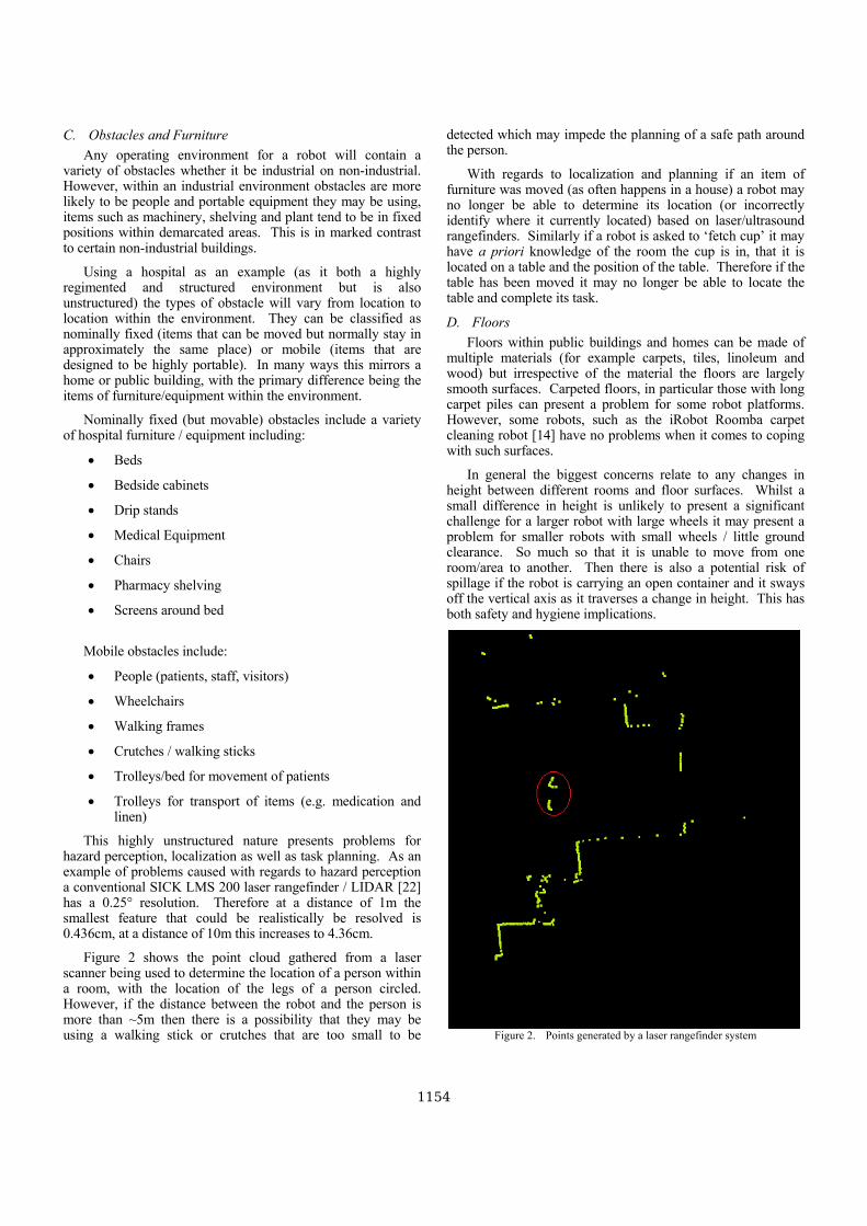
C. Obstacles and Furniture Any operating environment for a robot will contain a
variety of obstacles whether it be industrial on non-industrial. However, within an industrial environment obstacles are more likely to be people and portable equipment they may be using, items such as machinery, shelving and plant tend to be in fixed positions within demarcated areas. This is in marked contrast to certain non-industrial buildings.
Using a hospital as an example (as it both a highly regimented and structured environment but is also unstructured) the types of obstacle will vary from location to location within the environment. They can be classified as nominally fixed (items that can be moved but normally stay in approximately the same place) or mobile (items that are designed to be highly portable). In many ways this mirrors a home or public building, with the primary difference being the items of furniture/equipment within the environment.
Nominally fixed (but movable) obstacles include a variety of hospital furniture / equipment including:
• Beds
• Bedside cabinets
• Drip stands
• Medical Equipment
• Chairs
• Pharmacy shelving
• Screens around bed
Mobile obstacles include:
• People (patients, staff, visitors)
• Wheelchairs
• Walking frames
• Crutches / walking sticks
• Trolleys/bed for movement of patients
• Trolleys for transport of items (e.g. medication and linen)
This highly unstructured nature presents problems for hazard perception, localization as well as task planning. As an example of problems caused with regards to hazard perception a conventional SICK LMS 200 laser rangefinder / LIDAR [22] has a 0.25° resolution. Therefore at a distance of 1m the smallest feature that could be realistically be resolved is 0.436cm, at a distance of 10m this increases to 4.36cm.
Figure 2 shows the point cloud gathered from a laser scanner being used to determine the location of a person within a room, with the location of the legs of a person circled. However, if the distance between the robot and the person is more than ~5m then there is a possibility that they may be using a walking stick or crutches that are too small to be
detected which may impede the planning of a safe path around the person.
With regards to localization and planning if an item of furniture was moved (as often happens in a house) a robot may no longer be able to determine its location (or incorrectly identify where it currently located) based on laser/ultrasound rangefinders. Similarly if a robot is asked to ‘fetch cup’ it may have a priori knowledge of the room the cup is in, that it is located on a table and the position of the table. Therefore if the table has been moved it may no longer be able to locate the table and complete its task.
D. Floors Floors within public buildings and homes can be made of
multiple materials (for example carpets, tiles, linoleum and wood) but irrespective of the material the floors are largely smooth surfaces. Carpeted floors, in particular those with long carpet piles can present a problem for some robot platforms. However, some robots, such as the iRobot Roomba carpet cleaning robot [14] have no problems when it comes to coping with such surfaces.
In general the biggest concerns relate to any changes in height between different rooms and floor surfaces. Whilst a small difference in height is unlikely to present a significant challenge for a larger robot with large wheels it may present a problem for smaller robots with small wheels / little ground clearance. So much so that it is unable to move from one room/area to another. Then there is also a potential risk of spillage if the robot is carrying an open container and it sways off the vertical axis as it traverses a change in height. This has both safety and hygiene implications.
Figure 2. Points generated by a laser rangefinder system
1154
This problem could be remedied through minor improvements to the floors, such improvements may also be of particular benefit to the safety of the elderly and infirm. Indeed any environment occupied by someone in a wheelchair should, in theory, be automatically be suitable (with regards to floors) for a robot as there would be some similar challenges regarding mobility.
E. Stairs and Elevators Stairs and elevators are common place throughout hospitals,
public buildings and apartment blocks. With elevators being used as the primary means of getting from one floor to another. Building automation technologies could allow a robot to interact with and use an elevator. However the vast majority of houses reply on stairs to get from one floor to another.
This presents a significant challenge with respect to deploying a robot in a house (especially if the primary purpose of the robot is to enable someone to live at home), requiring specialized robot platforms or robot stair lift (similar to a wheelchair stair lift). Whilst stair climbing robots do exist it can be reasonably argued they are still laboratory based systems and that there are no commercial off the shelf platforms that have this ability [23].
Steps and stairs also present a safety issue for mobile service robots. A robot may be able to detect stairs going upwards using normal navigation sensors but these sensors normally wouldn’t enable the detection of steps or stairs going downwards. Therefore additional sensors that detect a fall in ground level are required. However, they are comparatively trivial to implement.
F. Summary Within any building or environment that has not been
designed to be used by mobile service robots there are numerous problems. In general they fall under the categories of localization, navigation, mobility and safety.
The problems themselves range from those that can solved or mitigated through building automation technologies, such as enabling a robot to open doors or call an elevator. All the way to those that are likely to require non-trivial modifications to the robot platform and to the deployment environment, such as negotiating stairs.
IV. INTERACTION CHALLENGES OF OPERATING IN A HUMAN POPULATED ENVIRONMENT
As well as ‘healthy able-bodied adults’ an environment may contain people who have various physical impairments or illnesses. This raises numerous challenges for both navigation within an environment and human-robot interaction. Because of an aging society (where assistive robots are required) and significantly increased rights for the disabled (especially in Europe and N. America) these issues can no-longer be ignored. For example the Equalities Act 2010 [24] in the United Kingdom allows penalties to be imposed on organizations failing to provide equal access for the disabled as well as for the person to seek damages for discrimination.
The significance of these impairments will depend a great deal upon the application domain of the robot and the types and
methods of interaction required. However, certain challenges will be universal in nature and need to be seriously considered at the system design stage. The following subsections discuss the impairments and the challenges they may present for the system designer.
A. Impaired mobility Impaired mobility is a condition or function judged to be
significantly impaired relative to the usual standard of an individual or their group. Within the domestic, hospital, public and care-home environments multiple forms of impaired mobility can be present:
• Use of crutches, walking frames or walking sticks that can restrict the speed and maneuverability with which a person walks
• Reduced walking speed due to a physical condition or old age
• Inability to walk for any distance without the need to stop and recover because of illness
This creates several potential challenges for a mobile robot examples of which include:
• Interaction with the Human Robot Interface if no hands are free to use the interface (for example a person with a broken leg using crutches)
• Defining and maintain a suitable speed if a robot is guiding a person
• Being able to deal with people who stop walking or slow down whilst being guided
• Stalemate between robot and person when neither the person nor robot can move past each other
B. Visual impairment Visual impairment limits the ability of a person to see, the
most common forms listed below can be corrected using glasses, contact lenses or surgery:
• Myopic - unable to see distant objects clearly, commonly called near-sighted or short-sighted
• Hyperopic - unable to see close objects clearly, commonly called far-sighted or long-sighted
So long as the above groups wear their corrective lenses
they will present no issue for service robots. However, if for whatever reason they do not have their glasses then Hyperopic people may have difficulty using a computer screen for interaction and Myopic people may have issues related to seeing the robots from a distance.
Within public buildings, hospitals, care homes and domestic buildings there is a possibility that there may be people with more severe vision problems that could be encountered by the robots. The varying levels of visual impairment are often classified as follows:
• Partially sighted indicates some type of visual problem that would of required special education
1155
• Low vision generally refers to a severe visual impairment, not necessarily limited to distance vision. Low vision applies to all individuals with sight who are unable to read the newspaper at a normal viewing distance, even with the aid of eyeglasses or contact lenses
• Legally blind the definition varies for a person can be registered as blind if their visual acuity is 3/60 or worse (they can see at three metres, or less, what a person with normal vision can see at 60 metres); or 6/60 if their field of vision is very restricted. The US definition of legally blind indicates that a person has less than 20/200 vision in the better eye or a very limited field of vision (20 degrees at its widest point)
• Totally blind total inability to see (it should be stated that such people may be being guided around by a person with normal sight)
These four groups present two challenges to the developer of a service robot system:
• Inability to use the screen (and potentially buttons) as a means of interaction with the robot therefore requiring oral and aural interface
• Inability to see the robot, this would create issues in terms of use/interaction with robot and also awareness/avoidance of the robots
C. Auditory impairment Auditory or hearing impairment is a full or partial decrease
in the ability to detect or understand sounds. It can be caused by a wide range of biological and environmental factors. It does present fewer challenges than vision loss but does require that communication from the robot is both audio and visual. So for example if a robot has a warning buzzer (similar to a reversing vehicle) its functionality ought to augmented with a warning light.
D. Speech disorders Speech disorders or speech impediments, as they are also
called, are a type of communication disorder where 'normal' speech is disrupted. This can mean stuttering, lisps, vocal dysphonia etc. Someone who is totally unable to speak due to a speech disorder is considered mute.
This would require that service robots cannot rely exclusively on speech based interaction and needs to have an additional non speech-recognition based interface to cater for those who are mute. People with lisps or stutters may be perfectly capable of communicating aurally with other people. However these factors could present a challenge for speech recognition systems once again necessitating the provision of some non-speech command based interface. This is also true for people with strong regional accents / dialects or non-native national accents.
E. Wheelchair bound people Wheelchairs are used either by disabled people in their
homes and for going about their daily lives or by patients and staff within a hospital / care-home environment to transport a
person with impaired mobility from one location to another. Therefore wheelchairs will present another obstacle for the robots to navigate around. If the person using the wheelchair themselves has a need to interact then issues regarding the interface and its accessibility arise. It may be necessary for two interfaces to be provided one at a height that is comfortable for able-bodied people to use and another for wheelchair bound people.
F. Hospital and Care-home patients This is an issue that is fairly specific to the hospital, hospice
and care-home environment where it is highly probable that there will be people undergoing some form of medical treatment. Some of these patients may be connected to sensitive medical equipment where it might be deemed to be inappropriate for the robot to be use radio signal communications if close by. A survey as part of the IWARD project identified intensive care units and special care baby units as the areas of most concern in relation to electromagnetic interference [25]. This would require such areas to be either designated as out of bounds for the robot (either permanently or temporarily) within the navigation and localization system or to be fitted with a beacon that alerts the robot. So that either wireless communications are temporarily suspended or the navigation system avoids the area.
G. Summary The different illnesses or physical impairments a person
could have present a variety of issues above and beyond those of the non-industrial environment. These create the following generic requirements for robots (some of which may be beneficial for robots in industrial environments):
• The Human Robot Interface must have multiple modalities available (there is also a requirement that any surfaces should be hygienic and cleanable if a robot is deployed in a hospital or care-home environment)
• Robot speed must be appropriate / adaptable if guiding people with mobility difficulties
• Robots need to be able to navigate in an environment even if people cannot see them (human avoidance of robot cannot be relied upon)
• In a hospital environment patients could be connected to sensitive medical devices, in such situations radio communications may need to be temporarily suspended or avoided by the robot
V. CONCLUSIONS The work shown in this paper has illustrated that there are
numerous challenges that need to be overcome for robots to successfully work in non-industrial environments (with a focus on homes and hospitals). These include the problems caused by an environment not having been designed to be robot-friendly, the unstructured nature of the environment and finally the difficulties that certain user populations may have interacting with a robot.
Some of these challenges are comparatively trivial to overcome, such as ensuring floors are level surfaces. This then
1156

progresses to problems that will require some effort to overcome (but are not insurmountable), for example providing multi-modal user interfaces. Whilst others still require a significant amount of research and development, this includes being able to traverse flights of stairs and being able to operate autonomously in non-structured environments.
Therefore there is significant scope for future work to make mobile service robots better able to cope with unstructured environments and the many challenges they present. This could include creation of a framework for developing mobile robots that operate outside of industrial environments.
ACKNOWLEDGMENT The research presented in this paper was conducted as part
of the EC FP6 Intelligent robot swarm for attendance, recognition, cleaning and delivery (IWARD) and the EC FP7 Multi-Role Shadow Robotic System for Independent Living (SRS) projects.
REFERENCES [1] http://www.iward.eu Accessed February 2012 [2] http://www.srs-project.eu Accessed February 2012 [3] J. Engleberger, Robotics in Service, MIT Press, MA. ISBN-10:
0-262-05042-0, ISBN-13: 978-0-262-05042-5 [4] "IFR World Robotics 2008 2007: 6.5 million robots in operation world-
wide", Industrial Robot: An International Journal, Vol. 36 Iss: 4, [5] J. L. Dallaway, R. D. Jackson, and P. H.A: “Timmers: Rehabilitation
robotics in Europe”, IEEE Transactions on Rehabilitation Engineering, 3(1):35–45, March 1995.
[6] Exact Dynamics "iARM": 2012, http://www.exactdynamics.nl/site/?page=iarm. Accessed Feb. 2012.
[7] J. Osada , S. Ohnaka , M. Sato: “The scenario and design process of childcare robot”, PaPeRo, Proceedings of the 2006 ACM SIGCHI international conference on Advances in computer entertainment technology, June 14-16, 2006, Hollywood, California
[8] R. W. Hicks and E. L. Hall: “A survey of robot lawn mowers”, D.P. Casasent, editor, Proc. SPIE Intelligent Robots and Computer Vision XIX: Algorithms, Techniques, and Active Vision, volume 4197, pages 262–269, 2000.
[9] B. Graf, M. Hans, Schraft, D. Rolf: “Care-O-bot II - Development of a Next Generation Robotic Home Assistant”, Autonomous Robots 16 (2004), Nr. 2, S. 193-205
[10] Giraffe robot: 2012 http://www.giraff.org/ Accessed Feb. 2012. [11] B. Graf, U. Reiser, M. Hagele, K. Mauz, P. Klein: "Robotic home
assistant Care-O-bot® 3 - product vision and innovation platform,"
Advanced Robotics and its Social Impacts (ARSO), 2009 IEEE Workshop on , vol., no., pp.139-144, 23-25 Nov. 2009
[12] J. Bohren, R. B. Rusu, E. G. Jones, E. Marder-Eppstein, C. Pantofaru, M. Wise, L. Mosenlechner, W. Meeussen. S. Holzer: "Towards autonomous robotic butlers: Lessons learned with the PR2" Robotics and Automation (ICRA), 2011 IEEE International Conference on , vol., no., pp.5568-5575, 9-13 May 2011
[13] SonyAibo: 2012 http://www.sonyaibo.net/home.htm Accessed Feb. 2012.
[14] iRobot: 2012. http://store.irobot.com/corp/index.jsp. Accessed Feb. 2012.
[15] K. S. Hwang, K. J. Park, D. H. Kim, S. S. Kim, S. H. Park: "Development of a mobile surveillance robot", Control, Automation and Systems, 2007. ICCAS '07. International Conference on , vol., no., pp.2503-2508, 17-20 Oct. 2007
[16] J. Ryu, H. Shim, S. Kil; E. Lee, H. Choi, S. Hong: "Design and implementation of real-time security guard robot using CDMA networking," Advanced Communication Technology, 2006. ICACT 2006. The 8th International Conference , vol.3, no., pp.6 pp.-1906, 20-22 Feb. 2006
[17] S. Thiel, D. Habe, M. Block: "Co-operative robot teams in a hospital environment," Intelligent Computing and Intelligent Systems, 2009. ICIS 2009. IEEE International Conference on , vol.2, no., pp.843-847, 20-22 Nov. 2009
[18] M. Mast, M. Burmeister, E. Berner, D. Facal, L. Pigini, L. Blasi: “Semi-autonomous teleoperated learning in-home service robots for elderly care: a qualitative study on needs and perceptions of elderly people, family caregivers, and professional caregivers” Proceedings of the twentieth International Conference on Robotics and Mechatronics, "SRS" Invited Session, 06-09 October 2010, Varna Bulgaria
[19] http://www.abloy.com Accessed February 2012 [20] L. Peterson, D. Austin, D. Kragic, "High-level control of a mobile
manipulator for door opening," Intelligent Robots and Systems, 2000. (IROS 2000). Proceedings. 2000 IEEE/RSJ International Conference on , vol.3, no., pp.2333-2338 vol.3, 2000 doi: 10.1109/IROS.2000.895316
[21] A. Diosi and L. Kleeman. Advanced sonar and laser range finder fusion for simultaneous localization and mapping. Proceedings of IEEE/RSJ International Conference on Intelligent Robots and Systems, pages 1854–1859, October 2 2004.
[22] SICK, Technical Description LMS200/211/221/291 Laser Measurement Systems https://www.mysick.com/saqqara/get.aspx?id=im0012759 Accessed February 2012
[23] M.M. Moghadam, M. Ahmadi, “Climbing Robots”, in Bioinspiration and Robotics: Walking and Climbing Robots, Eds. M.K. Habib, ISBN 978-3-902613-15-8, pp. 544, I-Tech, Vienna, Austria, EU, September 2007
[24] The Equality Act 2010 (Disability) Regulations 2010, ISBN 9 7801 0541 5107
[25] IWARD Deliverable 1.1.1 Technical report with the description of the environment and the application domain of the robot swarm, including the robot monitoring and supporting tasks, 2007.
1157
Powered by TCPDF (www.tcpdf.org)

Fast and Accurate Plane Segmentation
in Depth Maps for Indoor Scenes
Rostislav Hulik, Vitezslav Beran, Michal Spanel, Premysl Krsek, Pavel Smrz
Brno University of Technology, Faculty of Information Technology
IT4Innovations Centre of Excellence
Bozetechova 2, 61266 Brno, Czech Republic
{ihulik, beranv, spanel, krsek, smrz}@fit.vutbr.cz
Abstract — This paper deals with a scene pre-processing task –
depth image segmentation. Efficiency and accuracy of several
methods for depth map segmentation are explored. To meet
real-time capable constraints, state-of-the-art techniques
needed to be modified. Along with these modifications, new
segmentation approaches are presented which aim at
optimizing performance characteristics. They benefit from an
assumption of human-made indoor environments by focusing
on detection of planar regions. All methods were evaluated on
datasets with manually annotated real environments. A
comparison with alternative solutions is also presented.
Kinect; depth map segmentation; plane detection; computer
vision; range sensing
I. INTRODUCTION
Image segmentation is a well-studied computer vision
task. Although depth map segmentation has common roots
with greyscale image segmentation, respective algorithms
generally differ. It is due to the presence of an additional
dimension – the depth. The depth information (and consecu-
tive normal estimation from depth images) is beneficial as
regions can be distinguished by a step in the depth or the
direction of normal vectors. Consequently, segmentation
algorithms are based primarily on depth- and normal com-
parison methods.
Existing approaches differ in their accuracy and speed.
To guarantee real-time performance, applications in robotics
search for a precise segmentation that makes use of simplest
possible methods. The simplification can come from an
additional constraint on the environment in which a robot
operates. For example, human-made objects (artefacts) can
be mainly expected in indoor scenes. The a priori
knowledge of their common shapes characterized by planar
regions can lead to special segmentation approaches – plane
detection (prediction).
The research reported in this paper focuses on plane de-
tection in indoor-scene depth maps. The task is taken as a
pre-processing step for further planar object detection (floor,
walls, table-tops, etc.) or rough segmentation of foreground
and background objects. Although widely-used devices for
capturing scene depth data (such as Kinect, PrimeSense, or
XtionPRO) provide also visual RGB data, we focus solely
on the depth data in this paper. The methods are then easily
adaptable to data from other sensors such as LIDARs.
Today, there is a large number of depth segmentation al-
gorithms usable in robotics. However, only few of them
meet strict low computational power consumption con-
straints. We studied and compared existing methods and
designed and implemented various modifications to reach
real-time capable performance while retaining the accuracy.
Common low-cost depth sensors suffer from specific
problems linked to such type of sensors. The major persist-
ing problem is a structural noise present in the depth data.
All reported methods are therefore optimized to depress this
kind of problem. A general intention is to wider applicabil-
ity of cheap range sensors in the field of precise and fast
environment perception.
Figure 1. Indoor kinect depth map example
2012 IEEE/RSJ International Conference onIntelligent Robots and SystemsOctober 7-12, 2012. Vilamoura, Algarve, Portugal
978-1-4673-1736-8/12/S31.00 ©2012 IEEE 1665

The rest of this paper is organized as follows: The next
section discusses previous work related to our research.
Section III takes on existing methods for depth map seg-
mentation and proposes their optimization with the aim to
achieve fast performance while keeping their stability and
precision. Section IV presents novel approaches for segmen-
tation of depth maps focused on planar regions typical for
indoor scenes. Experimental results and a comparison of
existing and new methods are discussed in Section V.
II. RELATED WORK
Last years brought a boom of cheap depth sensors used
for localization, map building, environment reconstruction,
object detection, and other tasks in robotics. A rapid devel-
opment of various methods for depth map processing fol-
lowed. Fast object detection usually incorporates pre-
processing of depth data.
Pulli and Pietikäinen [1] apply normal decomposition in
their approach. They explore various techniques of range
data normal estimation (comparing their performance and
accuracy on clean as well as noisy datasets). The techniques
include quadratic surface least squares [2] or LSQ planar
fitting [3]. A least-trimmed-squares method is utilized for
comparison. The normal estimation is done by detecting
roof and step edges. A similar approach is discussed in this
paper as well.
Another approach that uses a simple extraction of step
and roof edges in the depth map was introduced by Baccar
et al. [6]. Various approaches to fusion are presented such as
an averaging method, Dempster-Shafer combinations or the
Bernouilli’s rule. After combination rules are applied, an
edge gradient map is created which is further used as an
input to the watershed algorithm. This algorithm is applied
to cope with the noise in depth maps.
Ying Yang and Förstner [7] present a plane detection
method that makes use of the RANSAC algorithm. The map
is split to tiles (small rectangular blocks). Three points are
iteratively tested for a plane region in each block. Detected
planes within a certain range are merged at the end. We
present an adaptation of this technique for indoor depth map
segmentation in this paper.
Other work that compares plane segmentation approach-
es and that generally inspired our research is presented
in [8]. Among other findings, authors mention their experi-
ence showing that RANSAC tends to over-simplify com-
plex planar structures, for example multiple small steps
were often merged into one sloped plane.
Borrmann et al. [9] present an alternative approach to
plane detection in point clouds based on 3D Hough trans-
form. Dube and Zell [10] also employ randomized Hough
transform for real-time plane extraction. Non-associative
Markov networks are applied for the same task in [11]. A
use of another method – multidimensional particle swarm
optimization – is reported in [12].
Zheng and Zhang [13] extend the range of detected regu-
lar surfaces from planes to spheres and cylinders. Elseberg
et al. [14] show how an octree- and RANSAC based method
can efficiently deal with large 3D point clouds containing
billions of special data points. Sithole and Mapurisa [15]
speed up the processing by means of profiling techniques.
Deschaud and Goulette [16] deal with efficiency issues as
well.
Although our implementation is independent, we appre-
ciate availability of the Point Cloud Library (point-
clouds.org) developed by Willow Garage experts [17].
III. FAST DEPTH MAP SEGMENTATION
As mentioned above, we analysed several approaches to
depth image segmentation focusing on efficient strategies
enabling fast pre-processing that is potentially integrable
into further environment perception tasks.
A first set of explored algorithms comprises modifica-
tions of existing segmentation methods. To meet require-
ments limiting computing time and power in typical robotic
scenarios, we simplified the work of Baccar et al. [6]. This
resulted in algorithms combining depth and normal infor-
mation with morphological watershed segmentation.
Baccar et al. distinguish two approaches to depth image
edge extraction – one is based on step edges and the other
one on roof edges (depth- and normal edge extraction in our
terminology). We tested these approaches and evaluated
their performance and usability in environment perception
tasks.
A. Depth based edge extraction
The detection of step edges presents the fastest segmen-
tation method as it is simple to compute on depth images.
The original work implements the step edge detector using
local image approximation by smooth second order poly-
nomials and subsequent computation of first- or second-
order derivatives. The authors state that this approach is
fast. We experimented with it and decided to go even fur-
ther and use only ordinal arithmetic to speed up the process.
Because of large structural noise present in Kinect depth
images, it is still necessary to emulate the smoothing capa-
bility of second-order polynomials. This was done by taking
into account the neighbourhood and computing the value of
extracted edge according to the following formula:
( ) ∑ { | ( ) ( )| ( ) (1)
where t is the threshold depth difference specifying a step
edge, W is the window of neighbouring pixels and d is a
depth information at pixel x. This approach was chosen for
its maximum speed and simplicity. A gradient map, with
pixels representing steepness of edges, is generated as an
output.
B. Normal based edge extraction
Normal based edge detection, called extraction of roof
edges in the original paper, was taken as a part of hybrid
segmentation. In order to meet the computational speed
requirements, we simplified this method and implemented it
in a standalone module.
The edge extraction method is slightly more computa-
tionally expensive than the depth based segmentation, be-
cause the normal computation on noisy image must forerun.
Instead of the normal estimation from second order poly-
1666
nomials, we applied the principle of accumulator edge ex-
traction again. Normal vectors are computed directly (using
depth difference or least-squares fitting) and only normal
differences are taken into account. Value of pixel of
edge gradient image is computed as:
( ) ∑ { ( ) ( )
( ) (2)
where n is a normal vector (normalized) adjacent to speci-
fied pixel of a depth image. This approach is simple but it
has proven reliable in the context of noisy data from Kinect.
C. Fusion based edge extraction
Having the outputs from depth-based and normal-based
segmentation methods, a late fusion can be applied to pro-
duce accurate and stable results.
Several fusion schemes were presented in [6]. They
ranged from simple averaging to sophisticated methods such
as the Super Bayesian Combination for fusing two pieces of
evidence or the Dempster’s rule of combination.
We opted for the fastest combination technique again.
Both the depth-based and normal-based edge extractors take
advantage of binary accumulators. Since our segmentation
algorithm is based on the watershed method (see below), a
simple sum of the two outputs provides a robust combina-
tion. A necessary condition is to use the same kernel size in
the input methods. The output is then given by a linear
combination:
( ) ( ) ( ) (3)
where are appropriate weights. They are set to 1 to maintain ordinal computation in our experiments.
Table 1 summarizes all presented modifications.
D. Watershed segmentation
The linear combination used in the fusion-based edge
extraction (Section C) can significantly deform edge
strengths. For example, the strength of an edge detected by
both algorithms will be greater than the strength of an edge
detected by only one detector. This observation led us to the
use of watershed segmentation which provides robust means
to cope with such situations.
Applied modifications
Method Baccar et al. Hulik et al.
Depth-based
First- or second order
derivative computed
from second order
polynomials
Binary
accumulation
Normal-based Normals computed
from second order
polynomials
Binary
accumulation
Fusion-based Averaging, Super
Bayesian or Demp-
ster-Shafer
Weighted sum
Table 1. Summary of the original approach modifications
The concept of watershed segmentation can be explained
by the similarity of a gradient image and the Earth surface.
When it is iteratively flooded from regional minima and two
basins are about to merge, a “dam” separating the two wa-
tersheds is raised.
We adapted the segmentation technique by implement-
ing a simple minima-search algorithm. Knowing that the
input for segmentation is an edge-strength gradient image
(values represented by integers), we simply take each basin
as a union of connected points with values lesser than a
threshold.
This technique has proven to be reliable in the context of
integer-represented edge gradient images. The threshold can
be set close to zero as the edge extraction technique is gen-
erally insensitive to non-edge regions.
By applying the watershed segmentation to edge detec-
tors discussed above, we obtained three scene segmentation
methods, which were evaluated and compared:
1. depth-based segmentation (DS)
2. normal-based segmentation (NS)
3. segmentation by fusion of DS and NS (FS)
IV. NEW SEGMENTATION TECHNIQUES
In addition to the optimized methods proposed above,
we designed two novel approaches specifically tailored for
indoor scene segmentation. As mentioned in the Introduc-
tion, planar regions are typical for human-made indoor
environments. The new techniques make use of this fact by
focusing on plane detection in indoor scenes.
A. Plane prediction segmentation (PS)
A novel depth map segmentation method, inspired by
state-of-the-art approaches, is based on detecting local gra-
dients. The method benefits from an a priori assumption that
a majority of significant objects in the scene (objects to be
detected) are human-made. They are supposed to have pla-
nar faces or can be approximated by them. Two gradient
images are computed:
( ) ∑ { | ( ) ( )|
( ) (4)
( )
∑
{
(
| ( ) ( )|
| ( ) ( )| )
(| ( ) ( )|
| ( ) ( )| )
( ) (5)
where represents a real depth of a specified pixel and is
a predicted theoretical depth of a pixel computed as follows:
( ) ( ) ( ( ) ( )) ( ) (6)
defines a center point with specified gradient, ( ) is a
theoretical depth of a point x predicted from point c using
its gradient, from formula 5 is the number of changes in
1667
the process of detection in a current window. Changes are
defined as differences in thresholding in formula 4, e.g., if a
current pixel has been to 1, a precedent one to 0, the change
appeared. The value is used to identify a current region – a
large number of changes indicate a planar noisy area. This
value can be also used for statistical region merging.
The result is represented as an integer edge gradient im-
age, so it is easy to apply the described watershed segmenta-
tion method to obtain a desired region map.
B. Tiled RANSAC segmentation (RS)
In search for a very fast and reliable segmentation algo-
rithm for indoor depth scenes, we devised another solution
that uses RANSAC for the ground plane search. It came out
from the approach presented in [7]. We adapted the method
by turning a planar detection algorithm into a depth map
planar region segmentation procedure. The resulting algo-
rithm excels in the segmentation of indoor scene images in
which planar objects dominate.
To cope with the large computational cost of the RANSAC
search, we had to develop a specific algorithm for the plane
search which takes into account only small areas of the
scene. A depth image is covered by squared tiles which
define only a small search area for RANSAC, but sufficient-
ly large area for robust plane estimation from noisy images.
The algorithm is sketched in Figure 2.
Figure 2. Tiled RANSAC (RS) algorithm
In step 2.1, RANSAC is used to find an existing plane in
a current tile. This means a random search for plane candi-
dates from pixels that has not been segmented yet. A plane
is found if it has all three defining point connected, i.e.,
there are pixels on the triangle plane between all three trian-
gle vertices.
If a plane was found, a seed-fill algorithm will group all
connected plane points in the current tile (2.2.1). Seed fill-
ing is fast and it is executed only on a detected plane. Each
pixel is then seeded only once.
The last step (2.2.2) fills the rest of the depth map for
regions reaching borders. This spreads the region out of the
tile and prevents creation of artefacts that could result from
the tile search. If a large plane is found, this step also reduc-
es the number of tiles searched in further iterations of 2.1 by
pre-filling regions. The ability to fill regions outside the tile
borders ensures that identified planes are marked in the
whole depth image.
Because of its small random sample search, the tiled
RANSAC is often used in real-time systems. The algorithm
can reach speed of multiple frames per second.
V. EXPERIMENTAL RESULTS AND DISCUSSION
In order to evaluate proposed methods, we designed a
series of tests focusing on performance and accuracy. Each
frame of the dataset was manually annotated to represent an
ideal segmentation result (the ground truth). Figure 3 shows
an example of such annotation. We used 20 different manu-
ally annotated frames for the accuracy comparison and 20
30-second frame sequences to evaluate the computation
efficiency.
The output of all five methods was collected. The seg-
mentation was compared to the ground truth data and the
percentage of correctly/wrongly segmented pixels was
counted. Additionally, we provide a comparison with PCL’s
[17] RANSAC point cloud segmentation method. Due to the
parallelism in PCL’s method, we used OpenMP [18] library
to parallelise our solution as well. An average computation-
al time of the segmentation process run on 640x480-pixel
images was also measured (Intel Core i7-2620M, 2.70
GHz). Results are summarized in Table 2. The graph in
Figure 4 characterizes the performance of the methods rela-
tively to the results of the slowest/most accurate method.
As expected, the FS and RS algorithms provide the most
accurate segmentation. The FS algorithm was designed to
precisely detect roof and step edges and the watershed seg-
mentation method contributes to its robustness. The key
disadvantage is the high computation time, the second larg-
est among the proposed approaches. It is due to computation
of normals for the whole depth map. The computation must
be robust so that a large neighbourhood needs to be taken
into account (window size 7x7 – 11x11 pixels, larger neigh-
bourhoods would result in imprecise segmentation on ob-
ject’s boundaries as normals would be deformed by the
difference in depth).
Figure 3. Sample images from manually
annotated dataset
The tile RANSAC search (RS) has proven to be a pre-
cise segmentation method too. The machine comparison
results are almost the same as that of the FS method. More-
over, a visual comparison of the segmented images reveals
that the method eliminated a problem related to the border
noise. On the other hand, it gets into difficulties with planes
1. Compute normals 2. For each tile
2.1. Try to find an existing triangle using RANSAC
2.2. If found plane 2.2.1. Seed-fill the whole tile
2.2.2. Seed-fill
1668

consisting of a small number of inlier points – the normals
are not computed precisely. Resulting region images need to
be post-processed using a region merging metric which join
similar planes together. The computation time is also a
strong attribute of this method.
The PS method provides the same accuracy as the NS.
However, its results are far more acceptable than that of the
NS method when one compares the segmentations visually
(see Figure 4). It is due to the precise detection of planar
regions and the sensitivity to small details. Both methods
suffer from the same problem – if the difference between a
suggested plane and a real pixel is below a threshold, no line
is detected. This poses problems on rounded edges which
are detected as a local noise.
Also note that the performance of the PS and RS meth-
ods cannot be simply compared with other segmentation
algorithms, because of the a priori assumption on the scene
shape. The algorithms are expected to produce a noisy out-
put for outdoor scenes.
Figure 4. Time and accuracy relative to results of
the tested algorithms
It is clear that the DS algorithm is far more efficient in
speed than the others. It employs minimal floating point
arithmetic and minimal image computations. On the other
hand, it is also the least precise. This comes from its nature
– it does not detect roof shaped edges. Despite that, the
method is a good candidate for general pre-processing. It
precisely detects depth differences so that clear boundaries
of different objects can be easily identified. Accuracy prob-
lems arise when the method is used to distinguish large
continuous objects such as wall corners.
Comparing our methods with the PCL’s RANSAC ap-
proach, it is clear that we successfully speeded up the seg-
mentation process while retaining necessary precision. The
lower precision in PCL method is due to the global search
of compared algorithm. The local approach in our methods
has better results for depth image segmentation.
The graph in Figure 4 also clearly shows that the time
consumption of the PS method is minimal when compared
to its relatively high accuracy. Thus, the technique is also a
good candidate for inclusion in very fast depth image pre-
processors.
Figure 5 shows a visual output of all the methods on two
test samples. To better demonstrate the results, regions are
not post-processed by the hole-filling algorithm.
VI. CONCLUSIONS
Five different depth-map segmentation methods were
described and evaluated in this paper. We modified three
well-known segmentation techniques to minimize their time
constraints. Additionally, two new algorithms – the plane
prediction segmentation and the tile RANSAC search were
presented. They take advantage of the assumption on plane
dominance in indoor scenes.
Evaluations were run to assess the performance of the
implemented methods. Speed and accuracy figures were
compared on a dataset consisting of manually segmented
indoor scene images. A visual comparison of the resulting
segmentations was also performed. Although the machine-
computed accuracy of the methods is similar, the visual
comparison shows large differences. There are also signifi-
cant differences in speed.
The usability of the segmentation methods based on
plane detectors depends on the nature of the segmentation
task – these methods are precise in planar objects segmenta-
tions, non-planar ones can pose problems. It is recommend-
ed to post-process segmented images by region merging and
hole filling algorithms, which can significantly increase the
usability in practical applications.
In future, we are planning to further parallelise and op-
timise proposed methods to reach the real-time performance
(<33.3 s/frame). GPU implementations are not supposed
now because of use of these methods primarily on small,
embedded systems. Also, further analysis and comparison
with today’s segmentation methods is advised.
0
0,1
0,2
0,3
0,4
0,5
0,6
0,7
0,8
0,9
1
DS NS FS PS RS PCLTime (relative)
Accuracy (relative)
Method DS NS FS PS RS PCL
Correctly segmented (%) 73.11±20.39 83.41±16.63 87.35±10.86 83.40±10.32 86.21±10.62 78.67±12.95
Wrongly segmented (%) 23.49±18.29 13.04±11.49 10.22±8.96 15.44±9.41 11.71±8.25 19.02±9.16
Time (ms) 28.49±8.19 134.00±27.3
8 151.85±34.72 138.20±41.37 97.89±13.63
254.12±194.3
1
Table 2. Table comparing the accuracy and speed of implemented segmentation methods.
1669

ACKNOWLEDGMENTS
The research leading to these results has received fund-
ing from the European Union, 7th Framework Programme,
grant 247772 – SRS, Artemis JU grant 100233 – R3-COP,
and the IT4Innovations Centre of Excellence, grant
n. CZ.1.05/1.1.00/02.0070, supported by Operational Pro-
gramme “Research and Development for Innovations”
funded by Structural Funds of the European Union and the
state budget of the Czech Republic.
REFERENCES
[1] Pulli, K., Pietikäinen, M.: Range Image Segmentation Based on Decomposition of Surface Normals. University of Oulu, Finland, 1988.
[2] Besl P., Surfaces in Range Image Understanding, Springer-Verlag. New York, 1988.
[3] Taylor, R., Savini, M., Reeves A.: Fast Segmentation of Range Imagery into Planar Regions. Computer Vision, Graphics, and Image Processing, vol. 45, pp. 42-60, 1989.
[4] Rousseeuw, P., Leroy, A.: Robust Regression & Outlier Detection. John Wiley & Sons, 1987.
[5] Poppinga, J.; Vaskevicius, N.; Birk, A.; Pathak, K.: Fast plane detection and polygonalization in noisy 3D range images. Intelligent Robots and Systems, 2008. IROS 2008. IEEE/RSJ International Conference on , vol., no., pp.3378-3383, 22-26 Sept. 2008.
[6] Baccar M., Gee, L. A., Gonzalez, R. C. and Abidi, M. A.: Segmentation of Range Images Via Data Fusion and Morphological Watersheds. Pattern Recognition, Vol. 29, No. 10. (October 1996), pp. 1673-1687.
[7] Ying Yang, M., Förstner, W.: Plane Detection in Point Cloud Data. Proceedings of the 2nd International Conference on Machine Control Guidance Bonn (2010), Issue: 1, Pages: 95-104.
[8] Oßwald, S., Gutmann, J.-S., Hornung, A., Bennewitz, M.: From 3D point clouds to climbing stairs: A comparison of plane segmentation approaches for humanoids. In: Proceeding of the 11th IEEE-RAS International Conference on Humanoid Robots (Humanoids 2011), Bled, Slovenia, October 26-28, 2011
[9] Borrmann, D., Elseberg, J., Lingemann, and K., Nüchter, A.: The 3D Hough transform for plane detection in point clouds – A review and a new accumulator design. 3D research, Springer, Volume 2, Number 2, March 2011.
[10] Dube, D. and Zell, A.: Real-time plane extraction from depth images with the Randomized Hough Transform. In IEEE ICCV Workshop on Challenges and Opportunities in Robot Perception, pages 1084 -1091, Barcelona, Spain, November 2011.
[11] Shapovalov, R. and Velizhev, A.: Cutting-Plane Training of Non-associative Markov Network for 3D Point Cloud Segmentation. In Proceedings of the 2011 International Conference on 3D Imaging, Modeling, Processing, Visualization and Transmission (3DIMPVT’11). IEEE Computer Society, Washington, DC, USA, 2011, pp. 1-8.
[12] Wang, L., Cao, J. and Han, C.: Multidimensional particle swarm optimization-based unsupervised planar segmentation algorithm of unorganized point clouds. Pattern Recogn. 45, 11, November 2012. pp. 4034-4043.
[13] Zheng, P. and Zhang, A.: A Method of Regular Objects Recognition from 3D Laser Point Cloud. Lecture Notes in Electrical Engineering, 1, Volume 126, Recent Advances in Computer Science and Information Engineering, 2012. Pages 501-506.
[14] Elseberg, J., Borrmann, D., and Nüchter, A.: Efficient Processing of Large 3D Point Clouds. In Proceedings of the XXIII International Symposium on Information, Communication and Automation Technologies (ICAT '11), IEEE Xplore, ISBN 978-1-4577-0746-9, Sarajevo, Bosnia, October 2011.
[15] Sithole, G. and Mapurisa, W.T.: 3D Object Segmentation of Point Clouds using Profiling Techniques. South African Journal of Geomatics, Vol. 1, No. 1, January 2012.
[16] Deschaud, J. E., Goulette, F.: A fast and accurate plane detection algorithm for large noisy point clouds using filtered normals and voxel growing. In: Proceedings of the 5th International Symposium on 3D Data Processing, Visualization and Transmission (3DPVT'10), 2010.
[17] Rusu, R.B. and Cousins, B.:3D is here: Point Cloud Library (PCL). In: Proceedings of the International Conference on Robotics and Automation, 2011, Shanghai, China.
[18] Menon R., Dagum L.: OpenMP: an industry standard API for shared-memory programming. In: IEEE Computational Science and Engineering, Vol. 5, No. 1. (1998), pp. 46-55.
Figure 5. Output visualization: upper-left: manual, middle-left: DS, bottom-left: NS,
upper-right: CS, middle-right: PS, bottom-right: RS
1670