Embed Size (px)
Citation preview
CoRaSat COgnitive RAdio for SATellite Communications
FP7-‐ICT Collaborative Project -‐ Grant Agreement no.: 316779
Collaborative project
Deliverable D4.1 Proof of Concept Storyboard
Project acronym: CoRaSat Project full title: COgnitive RAdio for SATellite Communications Grant agreement no: 316779 Project web site: www.ict-corasat.eu
Deliverable No. D4.1
Delivery Date M24
Work Package No. WP4 Work Package Title: CoRaSat Test and Demonstration
Authors (Partner) (per Beneficiary, if more than one Beneficiary provide it together)
Joel Grotz (NTC)
Symeon Chatzinotas, Sina Maleki, Shree Sharma, Eva Lagunas (UL)
Konstantinos Liolis, Jens Krause (SES)
Alessandro Vanelli-‐Coralli, Alessandro Guidotti, Daniele Tarchi, Vincenzo Icolari, Giovanni Emanuele Corazza, Carlo Caini (UNIBO)
Paul Thompson, Barry Evans, Wuchen Tang (UNIS).
Status (F: final; D: draft; RD: revised draft): F
Dissemination level:
(PU = Public; PP = Restricted to other program
participants;RE = Restricted to a group specified by
the consortium;CO = Confidential, only for
members of the consortium.
PU
File Name: CoRaSat_Del_D4_1_r1_v0.doc
Project start date and duration 01 October 2012, 36 month

Release 1.0 pag. 2 of 50
INTENTIONALLY LEFT BLANK
ICT−316779 CoRaSat Deliverable D4.1
Release 1.0 pag. 3 of 50
TA B L E O F CO N T E N T S 1 EXECUTIVE SUMMARY ............................................................................................................................. 4
2 SCOPE AND STRUCTURE OF THE DOCUMENT .................................................................................. 5
3 METHODOLOGY FOR WP4 ........................................................................................................................ 6
4 SELECTED TECHNOLOGIES AND FSS SYSTEM .................................................................................. 8
PLATFORM ENABLING TECHNICAL REQUIREMENTS ..................................................................................... 9 4.1 DATABASE TECHNIQUE – SELECTED TEST CONTEXT ................................................................................ 10 4.2 RESOURCE ALLOCATION – SELECTED TEST CONTEXT .............................................................................. 11 4.3 BEAMFORMING – OPTIONAL TEST CONTEXT ............................................................................................ 11 4.4 SPECTRUM SENSING – SELECTED TEST CONTEXT ..................................................................................... 12 4.5 DYNAMIC CAPACITY ALLOCATION (DCA) – ENABLING TRANSMISSION TECHNOLOGY ............................ 13 4.6 PLATFORM - DEMONSTRATION CONTEXT DESCRIPTION ............................................................................ 14 4.74.7.1 Service requirements description ...................................................................................................... 17 4.7.2 FSS system elements .......................................................................................................................... 18 4.7.3 User Terminal characteristics ........................................................................................................... 22 4.7.4 Network Control Center (NCC) definition ........................................................................................ 24 4.7.5 Service definition ............................................................................................................................... 24
5 USE CASES .................................................................................................................................................... 26
DATABASE INTERACTION EMULATION (SCENARIO A, B) ........................................................................... 27 5.1 END-TO-END LINK EMULATION (SCENARIO A, B) ...................................................................................... 27 5.2 FS RECEIVER EMULATION (SCENARIO C) ................................................................................................... 27 5.3 FSS INSTALLATION AND COMMISSIONING ................................................................................................. 27 5.4 FSS TERMINAL OPERATION WHILE CHANGES TO FS LINK PARAMETERS OCCUR ........................................ 27 5.5 FSS TERMINAL OPERATION WITH FS LINK SETUP ...................................................................................... 28 5.6 FSS TERMINAL OPERATION IN UNKNOWN ENVIRONMENT ......................................................................... 28 5.7
6 TARGET PERFORMANCE INDICATORS .............................................................................................. 29
7 STORYBOARD OF TEST CASES .............................................................................................................. 30
8 SYSTEM CONTEXT FOR DEMONSTRATION ...................................................................................... 41
DATABASE EMULATOR (DBE) ................................................................................................................... 41 8.1 NETWORK CONTROL CENTER (NCC) AND GATEWAY EMULATOR (GWE) ................................................ 42 8.2 USER TERMINAL EMULATOR (UTE) ........................................................................................................... 42 8.3 CHANNEL EMULATOR (CHE) ..................................................................................................................... 42 8.4 CONTENT SERVER (CS) ............................................................................................................................. 44 8.5 APPLICATION CONTENT CLIENT (CC) ........................................................................................................ 45 8.6
9 CONCLUSIONS AND NEXT STEPS ......................................................................................................... 46
10 DEFINITION, SYMBOLS AND ABBREVIATIONS .............................................................................. 47
11 REFERENCES ............................................................................................................................................. 49
12 DOCUMENT HISTORY ............................................................................................................................ 50
ICT−316779 CoRaSat Deliverable D4.1
Release 1.0 pag. 4 of 50
1 EX E C U T I V E SU M M A R Y The aim of WP4 is the validation and demonstration of the CoRaSat concept through testbed implementation of the selected scenarios. This first document produced in the context of WP4 reports the output of Task 4.1, which aims at providing storyboard test-cases representative of the developed scenarios, use cases, and technologies, as well as at describing the test procedure. In particular, this document aims at defining the main goals of the demonstration platform versus the preceding work of scenarios selection, FSS end-to-end system definition, and technology evaluation and selection, which has been performed in the context of WP2 and WP3. It is worthwhile highlighting that the main goal of WP4 is the laboratory demonstration of a two-way FSS Ka-band link that reuses the non-exclusive frequency bands as defined in previous studies, and that aims at implementing those technologies that are appropriate and mature enough for the implementation of a system that reuses the non-exclusive frequencies in the FSS Ka-band.
We focus on mature techniques that can be implemented in a system context in the near future. The aim of the demonstration platform is to verify that end-to-end service requirements can be met and that the expected system level gain can be reached. In addition, it is verified that the interference into incumbent systems is kept under control and is limited to an acceptable level, where applicable.
It is therefore the main goal of the lab demonstration platform to consider all defined requirements in the context of WP4, as defined in the CoRaSat DoW [1], and to implement the full required demonstration of the techniques that are required for such a demonstration.
We therefore review the end-to-end system context and the defined requirements that are mapped to requirements for the demonstration platform. Furthermore we consider the possible implementation aspects of each technology that was adapted in D3.4 to the FSS Ka-band system. Moreover, we consider the required key performance indicators (KPIs), which were defined on both technology and system level.
In the context of D4.1, the proof of concept approach that is considered in WP4 is defined and the storyboard is elaborated that summarizes the test-cases which are run on the demonstration platform to demonstrate the defined technologies. This document therefore summarizes what is demonstrated and how it is demonstrated. In addition, each test-case is clearly linked to a KPI and requirement defined to track the storyboard test-cases versus defined system requirements and performance indicators.
Based on these defined test-cases collection (storyboard), we conclude the detailed requirements and high level architecture of the test setup as well as the testplan and procedure details in the sequel in documents D4.2 and D4.3.
ICT−316779 CoRaSat Deliverable D4.1
Release 1.0 pag. 5 of 50
2 SC O P E A N D ST R U C T U R E O F T H E DO C U M E N T This deliverable describes the basis for the demonstration work to be executed within WP4. This comprises a subset of scenarios and specific use cases that are to be demonstrated from a technology point of view. The basis is the technology work that has been executed in WP3, in particular the related identified enabling technologies for the usage of the cognitive techniques in combination with the identified scenarios and use cases.
This document is organized as follows:
Chapter 3 defines the WP4 overall proof of concept objectives and methodology and the connection to WP2 and WP3 outputs, as well as the expected outcome of WP4 activities.
Chapter 4 defines the scenarios subset that is to be considered for demonstration within WP4. This summarizes the scenarios and the specific use case context. The FSS end-to-end system is defined in details. Furthermore, the business target applications are summarized to define the context of the FSS system applications.
Chapter 5 defines the use cases specifically. This means that a set of use cases per scenarios is considered and derived from the defined FSS system that is investigated in details. These use cases are defined in terms of system level deployment, installation, geometric orientation, and link budget parameters.
Chapter 6 summarizes the target performance indicators and regulatory requirements that need to be met. This is a quantitative review of what needs to be met in terms of system level metrics to satisfy the requirements of the regulatory context for the different scenarios as well as the performance improvements. The parameters of the use cases are defined and the key output measurements that are linked to the KPI and regulatory metrics indicators are introduced.
Chapter 7 summarizes the test plan and describes the high level design requirements for the test setup (in preparation for D4.2). The test scenarios are described and outlined in relation to the defined performance indicators, use cases and scenarios. An overview matrix of scenarios, use cases, performance indicators, and test cases summarizes the high level test plan description.
Chapter 8 concludes on the intentions and expectations of the tests foreseen in WP4.
ICT−316779 CoRaSat Deliverable D4.1
Release 1.0 pag. 6 of 50
3 ME T H O D O L O G Y F O R WP4 WP4 foresees to validate and demonstrate the concepts and techniques elaborated throughout the project, and presents a test platform with use cases and results. The aspects that are covered within WP4 include the sharing of the frequency bands as well as the demonstration of potential overall gains in combination with the usage of cognitive techniques.
An example FSS system is defined that is related to the system evaluation from D3.4 as a basis for the evaluation. The overall requirements are drawn from the sharing of the frequency bands and the protection of incumbent user requirements, the requirements of the FSS system, as well as the performance indicators. In addition to the FSS example system (from D3.4), use cases are defined that reflect the expected situations of the FSS terminals in operation within the shared bands scenarios.
In a first step, the techniques defined and adapted in D3.3 [1] are reviewed and evaluated. The most promising and most mature for demonstration are selected for the demonstration platform for evaluation, and the reference mapping of the techniques to the FSS system reference is performed in D3.4. This evaluation includes the assessment of implementation aspects (maturity of the technique) as well as potential implementation challenges and promised outcome.
The demonstration is then oriented around the use cases defined that allow to evaluate the techniques in a lab setup. A selection might be necessary to prioritize to what is possible in the context of this project. This is defined in the context of this document.
The lab evaluation is defined in such a manner that the key performance indicators and the requirements can be evaluated through measurements or indirectly through measurements and system analysis. This leads to a test plan document D4.2 that is describing the tests and the procedures to evaluate the target parameters (i.e., test outcome parameters) under defined input parameters (i.e., use cases).
The test platform requirements are defined from the set of use cases, KPIs, and performance requirements. The test platform requirements specify the lab context requirements to sufficient details that a top level architecture for the lab test platform can be directly defined. A system and sub-system specification is derived for the system within the scope of D4.3.
The subsequent work of implementation and integration performed in D4.4 concentrates on the implementation of the hardware, firmware, and software components required to setup the lab test environment.
The overall setup is tested with respect to the defined testplan set in the context of D4.5.
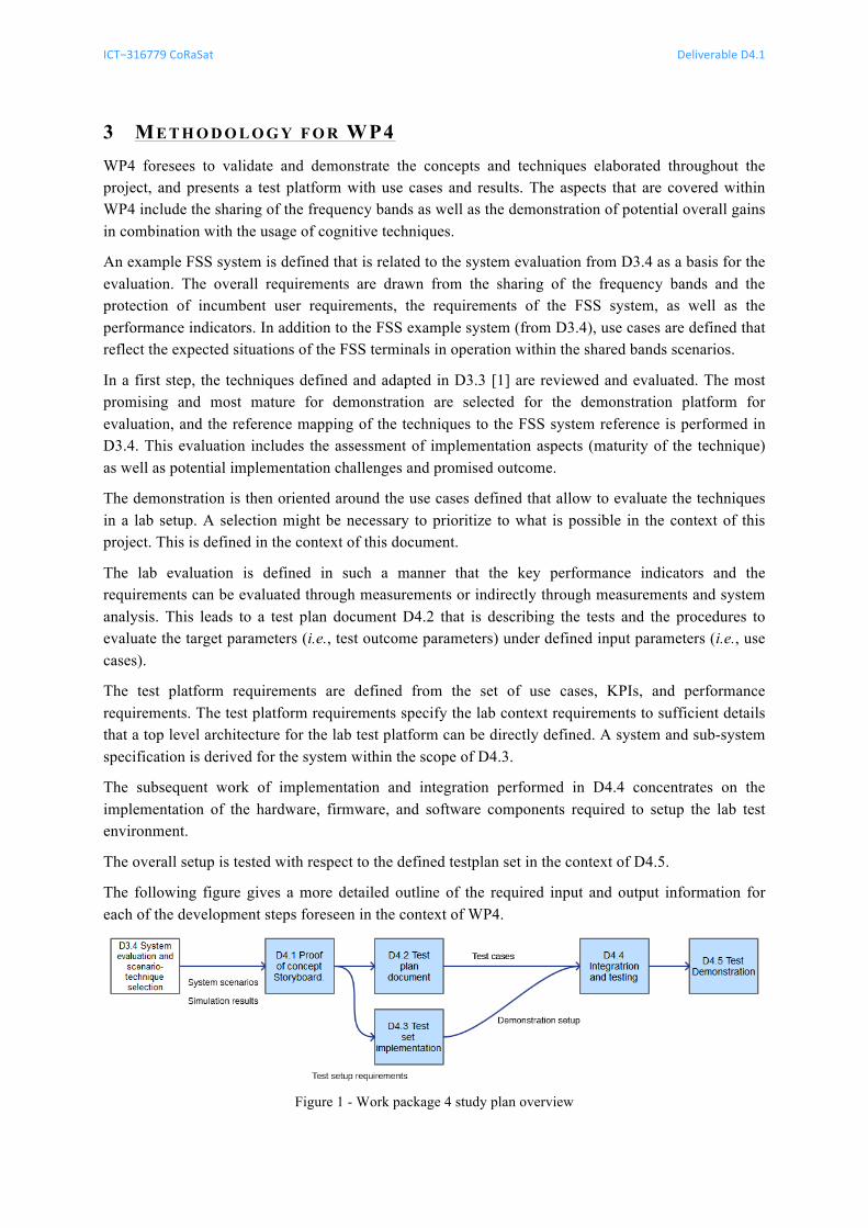
The following figure gives a more detailed outline of the required input and output information for each of the development steps foreseen in the context of WP4.
Figure 1 - Work package 4 study plan overview
ICT−316779 CoRaSat Deliverable D4.1
Release 1.0 pag. 7 of 50
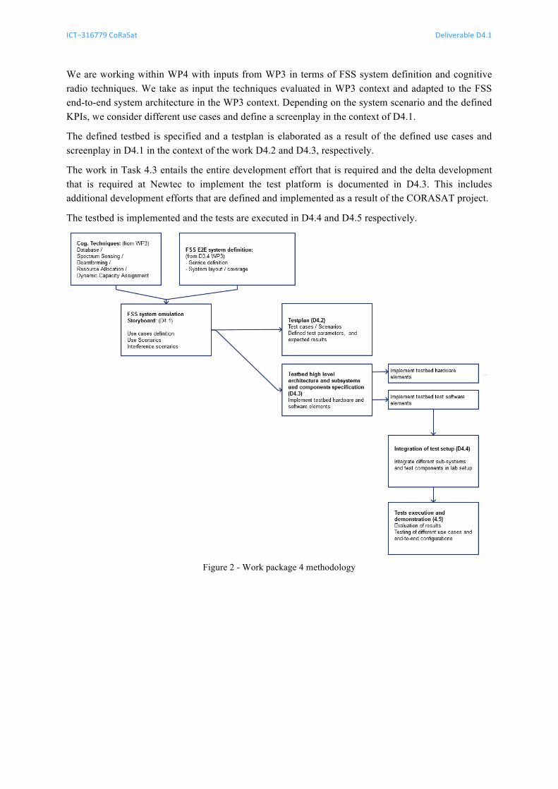
We are working within WP4 with inputs from WP3 in terms of FSS system definition and cognitive radio techniques. We take as input the techniques evaluated in WP3 context and adapted to the FSS end-to-end system architecture in the WP3 context. Depending on the system scenario and the defined KPIs, we consider different use cases and define a screenplay in the context of D4.1.
The defined testbed is specified and a testplan is elaborated as a result of the defined use cases and screenplay in D4.1 in the context of the work D4.2 and D4.3, respectively.
The work in Task 4.3 entails the entire development effort that is required and the delta development that is required at Newtec to implement the test platform is documented in D4.3. This includes additional development efforts that are defined and implemented as a result of the CORASAT project.
The testbed is implemented and the tests are executed in D4.4 and D4.5 respectively.
Figure 2 - Work package 4 methodology
ICT−316779 CoRaSat Deliverable D4.1
Release 1.0 pag. 8 of 50
4 SE L E C T E D TE C H N O L O G I E S A N D FSS SY S T E M In the following we define the techniques that are considered in the context of the demonstration platform and specifically the aspects that are down-selected for demonstration. The technologies as defined and adapted for the satellite system context are revised in D3.3 and the system level adaptation is performed in D3.4. The following summarizes the specific cognitive radio aspects that are considered and demonstrated to respond to the satellite system implementation requirements.
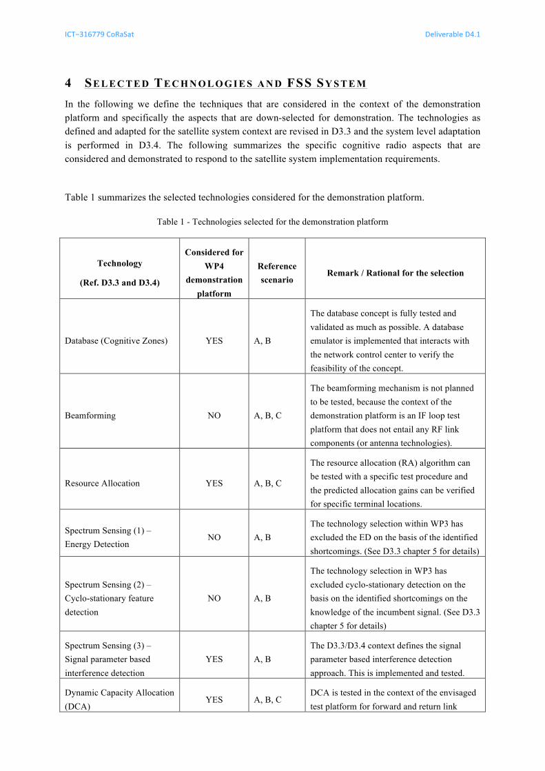
Table 1 summarizes the selected technologies considered for the demonstration platform.
Table 1 - Technologies selected for the demonstration platform
Technology
(Ref. D3.3 and D3.4)
Considered for WP4
demonstration platform
Reference scenario
Remark / Rational for the selection
Database (Cognitive Zones) YES A, B
The database concept is fully tested and validated as much as possible. A database emulator is implemented that interacts with the network control center to verify the feasibility of the concept.
Beamforming NO A, B, C
The beamforming mechanism is not planned to be tested, because the context of the demonstration platform is an IF loop test platform that does not entail any RF link components (or antenna technologies).
Resource Allocation YES A, B, C
The resource allocation (RA) algorithm can be tested with a specific test procedure and the predicted allocation gains can be verified for specific terminal locations.
Spectrum Sensing (1) – Energy Detection
NO A, B The technology selection within WP3 has excluded the ED on the basis of the identified shortcomings. (See D3.3 chapter 5 for details)
Spectrum Sensing (2) – Cyclo-stationary feature detection
NO A, B
The technology selection in WP3 has excluded cyclo-stationary detection on the basis on the identified shortcomings on the knowledge of the incumbent signal. (See D3.3 chapter 5 for details)
Spectrum Sensing (3) – Signal parameter based interference detection
YES A, B The D3.3/D3.4 context defines the signal parameter based interference detection approach. This is implemented and tested.
Dynamic Capacity Allocation (DCA)
YES A, B, C DCA is tested in the context of the envisaged test platform for forward and return link
ICT−316779 CoRaSat Deliverable D4.1
Release 1.0 pag. 9 of 50
(scenarios A, B and C).
Platform enabling technical requirements 4.1The selected techniques for the demonstration setup are documented already in WP3, and we here focus on the most promising techniques based on the possibilities an IF lab demonstration platform can demonstrate within the scope of this project.
It should be noted that, in addition to the techniques presented in the WP3, it is necessary to setup an end-to-end demonstration platform that has the necessary features to implement these techniques as defined. There are a number of essential requirements that need to be considered for this in the demonstration setup. These include the following elements mainly:
1. NCC centralized transmission plan
The hub setup should be subdivided into Network Control Center (NCC) and Gateway emulators (GWe) and it shall be possible for the NCC to collect and monitor all signal quality parameters of the terminals at forward link reception and for the return link at the demodulator input.
2. NCC centralized channel state monitoring
All required parameters for the spectrum sensing need to be collected at the NCC in sufficient regular intervals to enable the application of the SS-SNIR and the RA application.
3. Dynamic Capacity Assignment (DCA) on the Forward Link
The forward link to the end user terminals shall be capable of reallocating their forward link usage when required and directed by the NCC.
4. Dynamic Capacity Assignment (DCA) on the Return Link
The return link from the end user terminals shall be capable of reallocating their capacity allocation so that the usage of the return link assignment to different frequency bands is feasible. This is required as a basis to enable the flexible bandwidth allocation.
The considered techniques here are enabling technologies that are required to make the other techniques work as expected and to enable the implementation of the different cognitive techniques as defined in the WP3 context.
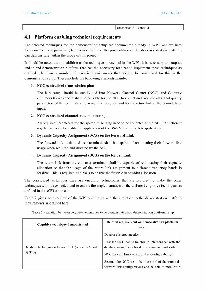
Table 2 gives an overview of the WP3 techniques and their relation to the demonstration platform requirements as defined here.
Table 2 - Relation between cognitive techniques to be demonstrated and demonstration platform setup
Cognitive technique demonstrated Related requirement on demonstration platform
setup
Database technique on forward link (scenario A and B) (DB)
Database interconnection:
First the NCC has to be able to interconnect with the database using the defined procedure and protocols.
NCC forward link control and re-configurability:
Second, the NCC has to be in control of the terminals forward link configurations and be able to monitor in
ICT−316779 CoRaSat Deliverable D4.1
Release 1.0 pag. 10 of 50
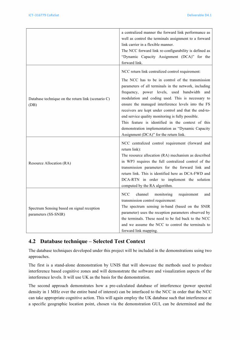
a centralized manner the forward link performance as well as control the terminals assignment to a forward link carrier in a flexible manner. The NCC forward link re-configurability is defined as “Dynamic Capacity Assignment (DCA)” for the forward link.
Database technique on the return link (scenario C) (DB)
NCC return link centralized control requirement:
The NCC has to be in control of the transmission parameters of all terminals in the network, including frequency, power levels, used bandwidth and modulation and coding used. This is necessary to ensure the managed interference levels into the FS receivers are kept under control and that the end-to-end service quality monitoring is fully possible. This feature is identified in the context of this demonstration implementation as “Dynamic Capacity Assignment (DCA)” for the return link.
Resource Allocation (RA)
NCC centralized control requirement (forward and return link): The resource allocation (RA) mechanism as described in WP3 requires the full centralized control of the transmission parameters for the forward link and return link. This is identified here as DCA-FWD and DCA-RTN in order to implement the solution computed by the RA algorithm.
Spectrum Sensing based on signal reception parameters (SS-SNIR)
NCC channel monitoring requirement and transmission control requirement: The spectrum sensing in-band (based on the SNIR parameter) uses the reception parameters observed by the terminals. These need to be fed back to the NCC and we assume the NCC to control the terminals to forward link mapping.
Database technique – Selected Test Context 4.2The database techniques developed under this project will be included in the demonstrations using two approaches.
The first is a stand-alone demonstration by UNIS that will showcase the methods used to produce interference based cognitive zones and will demonstrate the software and visualization aspects of the interference levels. It will use UK as the basis for the demonstration.
The second approach demonstrates how a pre-calculated database of interference (power spectral density in 1 MHz over the entire band of interest) can be interfaced to the NCC in order that the NCC can take appropriate cognitive action. This will again employ the UK database such that interference at a specific geographic location point, chosen via the demonstration GUI, can be determined and the
ICT−316779 CoRaSat Deliverable D4.1
Release 1.0 pag. 11 of 50
spectrum of such interference presented graphically. The demonstration will then indicate what action the NCC takes to address the interference.
Details of the interface between the interference database and the NCC/Network demonstrator are at an initial stage and will be refined as the demonstration is further refined.
In summary, for a chosen (via a GUI) location in the UK, the demonstration will show the potential interference (if any) at that site and how the NCC copes with such interference such that the FSS service requirements can be met.
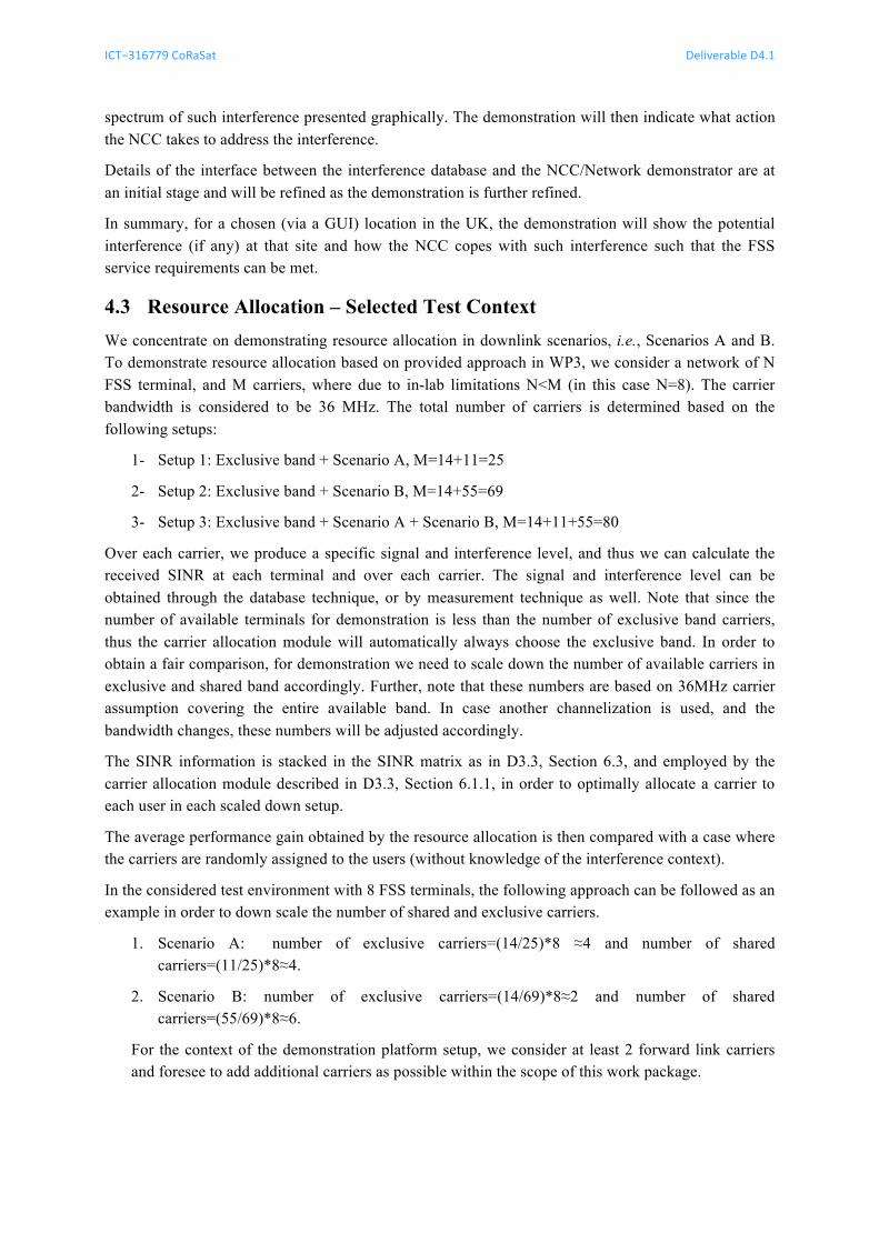
Resource Allocation – Selected Test Context 4.3We concentrate on demonstrating resource allocation in downlink scenarios, i.e., Scenarios A and B. To demonstrate resource allocation based on provided approach in WP3, we consider a network of N FSS terminal, and M carriers, where due to in-lab limitations N<M (in this case N=8). The carrier bandwidth is considered to be 36 MHz. The total number of carriers is determined based on the following setups:
1- Setup 1: Exclusive band + Scenario A, M=14+11=25
2- Setup 2: Exclusive band + Scenario B, M=14+55=69
3- Setup 3: Exclusive band + Scenario A + Scenario B, M=14+11+55=80
Over each carrier, we produce a specific signal and interference level, and thus we can calculate the received SINR at each terminal and over each carrier. The signal and interference level can be obtained through the database technique, or by measurement technique as well. Note that since the number of available terminals for demonstration is less than the number of exclusive band carriers, thus the carrier allocation module will automatically always choose the exclusive band. In order to obtain a fair comparison, for demonstration we need to scale down the number of available carriers in exclusive and shared band accordingly. Further, note that these numbers are based on 36MHz carrier assumption covering the entire available band. In case another channelization is used, and the bandwidth changes, these numbers will be adjusted accordingly.
The SINR information is stacked in the SINR matrix as in D3.3, Section 6.3, and employed by the carrier allocation module described in D3.3, Section 6.1.1, in order to optimally allocate a carrier to each user in each scaled down setup.
The average performance gain obtained by the resource allocation is then compared with a case where the carriers are randomly assigned to the users (without knowledge of the interference context).
In the considered test environment with 8 FSS terminals, the following approach can be followed as an example in order to down scale the number of shared and exclusive carriers.
1. Scenario A: number of exclusive carriers=(14/25)*8 ≈4 and number of shared carriers=(11/25)*8≈4.
2. Scenario B: number of exclusive carriers=(14/69)*8≈2 and number of shared carriers=(55/69)*8≈6.
For the context of the demonstration platform setup, we consider at least 2 forward link carriers and foresee to add additional carriers as possible within the scope of this work package.
ICT−316779 CoRaSat Deliverable D4.1
Release 1.0 pag. 12 of 50
Beamforming – Optional Test Context 4.4Hardware implementation of antenna beamforming will not be considered in the demonstration platform, because as previously stated, the considered IF loop test platform does not entail any RF link components (or antenna technologies). However, the benefits of having more than one antenna at the FSS terminal side and adaptively controlling its relative phase to create a desired radiation pattern will be tested on the demon platform indirectly by means of software-based SINR gain ( BFG ). Basically, the values of SINR will be artificially increased by BFG to emulate the advantage of considering a beamforming antenna array at the terminal side,
BFBF GSINRSINR += (dB)
The beamforming design proposed in D3.3 preserves the desired response (i.e. with 0 dB) and minimizes the global output power with the previous constraint. Additionally, optional constraints can be put onto the interfering directions. Therefore, not only the desired signal and the interferer links are affected but also the received noise power. The latter justifies why we should focus on SINR gains instead of interfering link attenuation solely.
Two alternative approaches are proposed to compute BFG in the demonstration platform: • Consider BFG as a fixed input parameter and compute it with the beamforming design
described in D3.3 off line by averaging a significant number of realizations, changing the location of interfering links and the received interference power.
• Compute BFG for the 8 FSS terminal user under consideration and for the specific interfering
links at hand using the beamforming algorithm presented in D3.3.
It should be noted that the computed SINR gain after employing beamforming is dependent on the SNR and INR values at the FSS terminal, off-axis angle towards the interfering FS station from its boresight direction and the gain pattern of the employed array structure. The antenna structure is assumed to be Multi-LNB (MLNB) based Feed Array Reflector (FAR) as described in Deliverable D3.2 and its gain patter is obtained using the GRASP tool. Other parameters such as the values of SNR, INR and off-axis angles are assumed to be obtained from the considered demo set up and the database.
Spectrum Sensing – Selected Test Context 4.5Spectrum sensing is tested over the demonstration platform at different levels. We consider a centralized network control center (NCC) that gathers the measurement information from the different terminals and processes an interference evaluation on a regular basis to assess whether the terminal experiences interference on the forward link (scenarios A and B).
Spectrum sensing is considered in the context of existing and defined system and terminal level parameters and in the context of additional parameters that can be used in case an out-of-band scanning mechanism is available at the terminal location or integrated with the terminal.
We consider the sensing techniques that have been studied and identified in the context of WP3. These include the energy detection (ED), cyclostationary feature detection (CS) and in-band signal to noise ratio based spectrum sensing (SS-SNIR). Within the document D3.3 it is has been outlined that the best fitting technique with the most appropriate approach is the SS-SNIR based spectrum sensing feature.
In the context of this project we aim at implementing the most promising technique from the set of spectrum sensing, and therefore focus mainly on the interference estimation. We foresee to
ICT−316779 CoRaSat Deliverable D4.1
Release 1.0 pag. 13 of 50
concentrate on the spectrum sensing using the in-band indicators (SS-SNIR), mainly the SNIR and the power levels measured at the gateways for each return link traffic / carrier and at the terminal for the forward link carriers. We consider here as input parameters the signal quality indicators available on the terminal, such as the signal to noise and interference ratio and the error rate measurements and the signal power measurements (C0). A description of the technique is outlined in document D3.3 and an elaborate algorithm definition is derived in the context of the adaptation to the system context in D3.4 and for the test setup specification in D4.3.
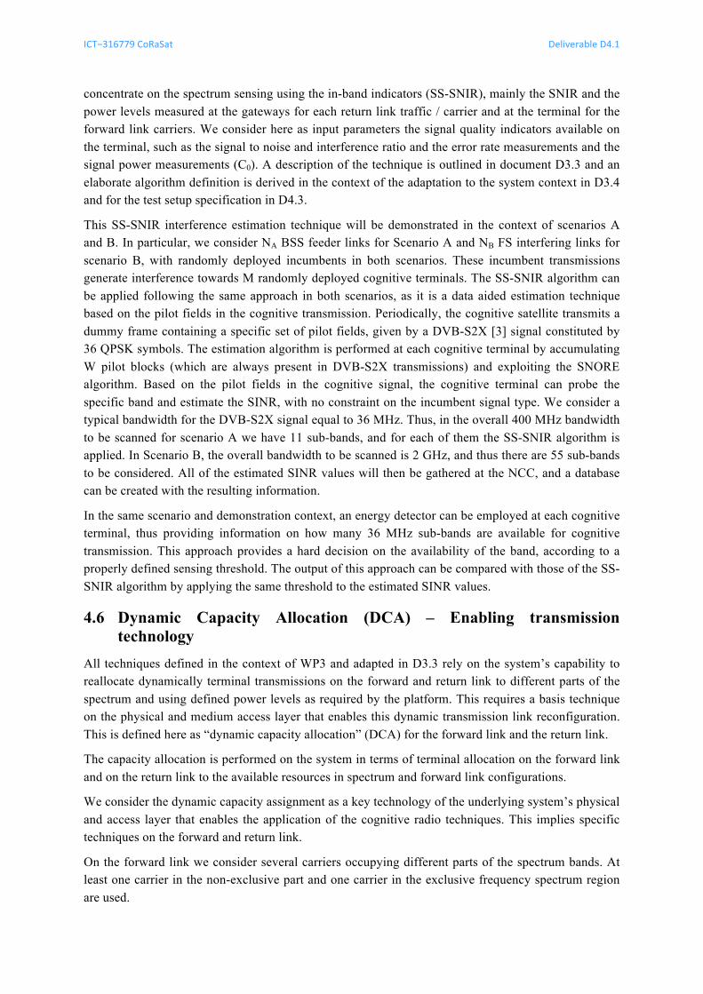
This SS-SNIR interference estimation technique will be demonstrated in the context of scenarios A and B. In particular, we consider NA BSS feeder links for Scenario A and NB FS interfering links for scenario B, with randomly deployed incumbents in both scenarios. These incumbent transmissions generate interference towards M randomly deployed cognitive terminals. The SS-SNIR algorithm can be applied following the same approach in both scenarios, as it is a data aided estimation technique based on the pilot fields in the cognitive transmission. Periodically, the cognitive satellite transmits a dummy frame containing a specific set of pilot fields, given by a DVB-S2X [3] signal constituted by 36 QPSK symbols. The estimation algorithm is performed at each cognitive terminal by accumulating W pilot blocks (which are always present in DVB-S2X transmissions) and exploiting the SNORE algorithm. Based on the pilot fields in the cognitive signal, the cognitive terminal can probe the specific band and estimate the SINR, with no constraint on the incumbent signal type. We consider a typical bandwidth for the DVB-S2X signal equal to 36 MHz. Thus, in the overall 400 MHz bandwidth to be scanned for scenario A we have 11 sub-bands, and for each of them the SS-SNIR algorithm is applied. In Scenario B, the overall bandwidth to be scanned is 2 GHz, and thus there are 55 sub-bands to be considered. All of the estimated SINR values will then be gathered at the NCC, and a database can be created with the resulting information.
In the same scenario and demonstration context, an energy detector can be employed at each cognitive terminal, thus providing information on how many 36 MHz sub-bands are available for cognitive transmission. This approach provides a hard decision on the availability of the band, according to a properly defined sensing threshold. The output of this approach can be compared with those of the SS-SNIR algorithm by applying the same threshold to the estimated SINR values.
Dynamic Capacity Allocation (DCA) – Enabling transmission 4.6technology
All techniques defined in the context of WP3 and adapted in D3.3 rely on the system’s capability to reallocate dynamically terminal transmissions on the forward and return link to different parts of the spectrum and using defined power levels as required by the platform. This requires a basis technique on the physical and medium access layer that enables this dynamic transmission link reconfiguration. This is defined here as “dynamic capacity allocation” (DCA) for the forward link and the return link.
The capacity allocation is performed on the system in terms of terminal allocation on the forward link and on the return link to the available resources in spectrum and forward link configurations.
We consider the dynamic capacity assignment as a key technology of the underlying system’s physical and access layer that enables the application of the cognitive radio techniques. This implies specific techniques on the forward and return link.
On the forward link we consider several carriers occupying different parts of the spectrum bands. At least one carrier in the non-exclusive part and one carrier in the exclusive frequency spectrum region are used.
ICT−316779 CoRaSat Deliverable D4.1
Release 1.0 pag. 14 of 50
The system can switch end-user traffic affectation between the two carriers and assign the terminal’s capacity to the required resource. This is controlled entirely from the centralized network control center.
As a second (return link capacity) dynamic capacity allocation technique, we implement a continuous carrier efficient return link based on HRC/MxDMA (high resolution coding multi-dimensional dynamic medium access). This is a DVB-RCS2 [4] like proprietary technique by Newtec that uses a flexible and efficient access to the spectrum to adapt to different traffic requirements. This technology is implemented in the latest DIALOG platform product by Newtec.
The technology is used in its capacity to adapt to different frequency resources and its potential to allocate capacity in different parts of the spectrum, as required by the planning constraints imposed by the NCC.
Platform - Demonstration context description 4.7In this section the end-to-end Ka-band multi-spot beam system is described. The lab demonstration modelling of the FSS system is explained and the demonstration approach outlined.
The lab demonstration platform entails the main elements listed in Table 3.
Table 3 - Elements for the demonstration platform
Scenario considered Demonstration context
A [17.3-17.7GHz], B [17.7-19.7GHz] The FSS terminal reception in scenarios A and B are emulated in IF band (L-band) and the spectrum occupation at the FSS terminal receiver input is emulated.
C [27.5-29.5GHz]
The FS receiver input is emulated in IF (L-band) so that multiple FSS links in the vicinity of the FS receiver are transmitting simultaneously. The aggregate interference experienced by the FS link receiver is measured in this configuration.
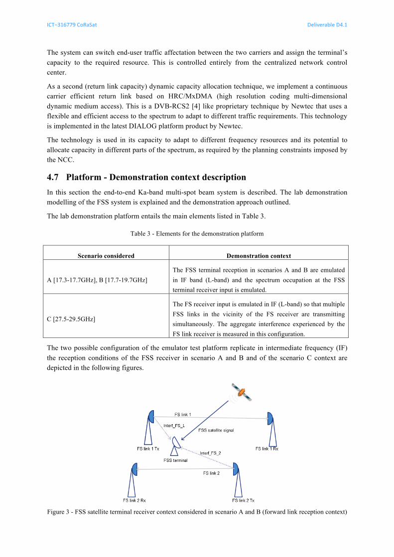
The two possible configuration of the emulator test platform replicate in intermediate frequency (IF) the reception conditions of the FSS receiver in scenario A and B and of the scenario C context are depicted in the following figures.
Figure 3 - FSS satellite terminal receiver context considered in scenario A and B (forward link reception context)
ICT−316779 CoRaSat Deliverable D4.1
Release 1.0 pag. 15 of 50
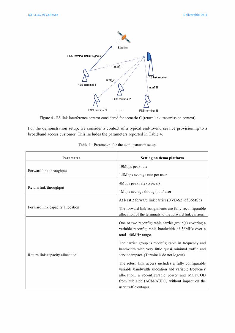
Figure 4 - FS link interference context considered for scenario C (return link transmission context)
For the demonstration setup, we consider a context of a typical end-to-end service provisioning to a broadband access customer. This includes the parameters reported in Table 4.
Table 4 - Parameters for the demonstration setup.
Parameter Setting on demo platform
Forward link throughput 10Mbps peak rate
1.5Mbps average rate per user
Return link throughput 4Mbps peak rate (typical)
1Mbps average throughput / user
Forward link capacity allocation
At least 2 forward link carrier (DVB-S2) of 36MSps
The forward link assignments are fully reconfigurable allocation of the terminals to the forward link carriers.
Return link capacity allocation
One or two reconfigurable carrier group(s) covering a variable reconfigurable bandwidth of 36MHz over a total 140MHz range.
The carrier group is reconfigurable in frequency and bandwidth with very little quasi minimal traffic and service impact. (Terminals do not logout)
The return link access includes a fully configurable variable bandwidth allocation and variable frequency allocation, a reconfigurable power and MODCOD from hub side (ACM/AUPC) without impact on the user traffic outages.
ICT−316779 CoRaSat Deliverable D4.1
Release 1.0 pag. 16 of 50
Emulated links
The emulated links in the platform include all satellite forward and return links to 8 terminals and a configuration for 2 forward links and 2 return groups for return link carriers.
The forward links are configured as DVB-S2 links in ACM configuration. The 8 terminals access the same forward carrier through generic stream encapsulation (GSE) multiplexed access.
On the return link, the configured terminals use a configured carrier group with dedicated SCPC carriers, which can be fully reconfigured while transmission. This includes frequency, symbol rate, power levels and used modulation and coding for the transmissions for each terminal.
Adaptations to Dynamic Capacity Assignments (DCA)
The adaptations required for the flexible bandwidth usage in the extended Ka-band for scenarios A, B and C includes the usage of dynamic capacity assignment on the forward and return link.
These DCA techniques include the possibility to reconfigure traffic assignments as required by the transmission plan.
For the forward link, the transmission reconfigurations require the reallocation of the terminal’s capacity to another forward link carrier. The traffic is reassigned to another forward link and the terminal is notified of the change via a control message. The details of the mechanism are outlined in document D3.4.
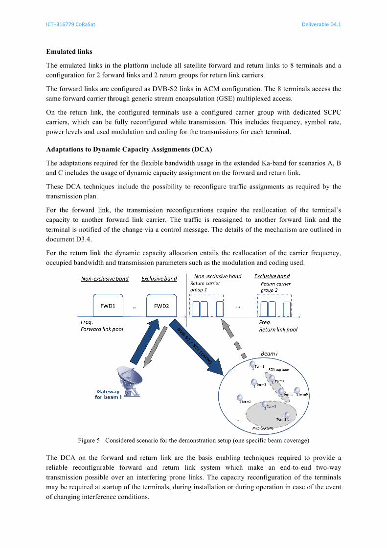
For the return link the dynamic capacity allocation entails the reallocation of the carrier frequency, occupied bandwidth and transmission parameters such as the modulation and coding used.
Figure 5 - Considered scenario for the demonstration setup (one specific beam coverage)
The DCA on the forward and return link are the basis enabling techniques required to provide a reliable reconfigurable forward and return link system which make an end-to-end two-way transmission possible over an interfering prone links. The capacity reconfiguration of the terminals may be required at startup of the terminals, during installation or during operation in case of the event of changing interference conditions.
ICT−316779 CoRaSat Deliverable D4.1
Release 1.0 pag. 17 of 50
For ESOMP terminals, the reconfiguration may be performed even in a scheduled regular manner during the operation of the terminal, in a relatively frequent manner.
In this manner the DCA on the forward and return link are enabling technologies that make the usage of the capacity possible in combination with the techniques described in D3.3 and adapted to the system level in D3.4 for the configuration and management of the capacity.
4.7.1 Service requirements description
In CoRaSat Deliverable D2.4 [5], service requirements were defined for the use of Cognitive Radio over SatCom. These requirements refer to the main technical qualitative requirements in order to meet the service, system and performance requirements as known today.
With respect to the proof-of-concept implementation, the applicable service requirements are provided hereinafter:
• REQ1. The proof-of-concept implementation shall provide support for the selected Ka-band scenario(s) to enable cost efficient utilization of Cognitive Radio solution in satellite communication.
• REQ2. The proof-of-concept implementation shall support the operation of FSS GSO satellite services in presence of BSS GSO satellite services without causing unacceptable interference to the incumbent system.
• REQ3. The proof-of-concept implementation shall support the operation of FSS GSO satellite services on ESOMP in presence of other GSO satellite services without causing harmful interference to the incumbent service.
• REQ4. The proof-of-concept implementation shall incorporate an agreed migration path to a future standard compliant version, as DVB and ETSI standards (e.g., evolutions of EN 302 307 V1.3.1 [3]).
• REQ5. The proof-of-concept implementation shall support justified evolutions of the DVB and ETSI standard families.
• REQ6. The proof-of-concept implementation shall be able to mitigate all in-band interference types, avoid out of band emissions as defined in DVB-S2, and avoid LNB saturation.
• REQ7. The proof-of-concept implementation shall have at least comparable system performances to current satellite COTS equipment (e.g., NEWTEC MDM 6x00 and MDM 3x00).
• REQ8. The proof-of-concept implementation shall support point-to-point and point-to-multipoint topologies.
• REQ9. The proof-of-concept implementation shall support the combination of at least two Cognitive Radio techniques.
• REQ10. The proof-of-concept implementation shall support GSO EIRP level variations of > 10 dB.
• REQ11. The proof-of-concept implementation shall support cost efficient automated terminal configuration, provide qualified installation procedures and built-in monitoring functions to enable remote configuration and maintenance operations.
ICT−316779 CoRaSat Deliverable D4.1
Release 1.0 pag. 18 of 50
• REQ12. The proof-of-concept implementation shall be based on and enable cost efficient deployment and operation of Cognitive Radio systems.
• REQ13. The proof-of-concept implementation shall support the operation of FSS satellite terminals in non-incumbent Ka-band spectrum allocations in and switch back to incumbent Ka-band operation when interference from is detected or announced from external systems.
• REQ14. The proof-of-concept implementation shall support effective measures against LNB saturation and measure to avoid non-linear operations.
Note regarding the requirements:
The REQ14 and partially REQ6 impact the LNB design, which is considered outside the scope of the current demonstration setup.
4.7.2 FSS system elements
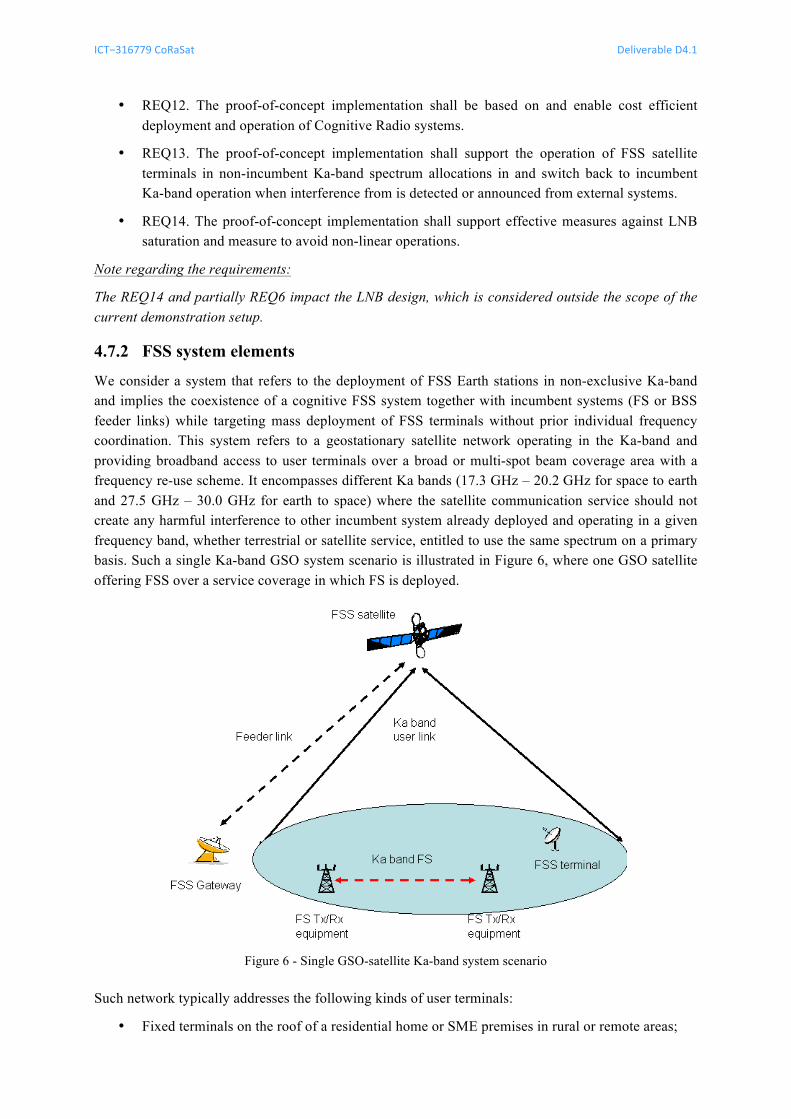
We consider a system that refers to the deployment of FSS Earth stations in non-exclusive Ka-band and implies the coexistence of a cognitive FSS system together with incumbent systems (FS or BSS feeder links) while targeting mass deployment of FSS terminals without prior individual frequency coordination. This system refers to a geostationary satellite network operating in the Ka-band and providing broadband access to user terminals over a broad or multi-spot beam coverage area with a frequency re-use scheme. It encompasses different Ka bands (17.3 GHz – 20.2 GHz for space to earth and 27.5 GHz – 30.0 GHz for earth to space) where the satellite communication service should not create any harmful interference to other incumbent system already deployed and operating in a given frequency band, whether terrestrial or satellite service, entitled to use the same spectrum on a primary basis. Such a single Ka-band GSO system scenario is illustrated in Figure 6, where one GSO satellite offering FSS over a service coverage in which FS is deployed.
Figure 6 - Single GSO-satellite Ka-band system scenario
Such network typically addresses the following kinds of user terminals:
• Fixed terminals on the roof of a residential home or SME premises in rural or remote areas;
ICT−316779 CoRaSat Deliverable D4.1
Release 1.0 pag. 19 of 50
• Mobile terminals on mobile platforms (ESOMPs) such as trains, vessels or aircrafts.
The satellite network provides connectivity between the user terminals and anchor gateways, which are also connected to the Public Internet. An anchor gateway can typically serve up to ten thousands of user terminals (professional market) or up to hundred thousand of terminals (consumer market) in a star topology. The system’s geostationary satellite also named “High Throughput Satellite” (HTS) typically generates between several tens and several hundred beams to achieve high transmission and reception gains towards the user terminals distributed across its service area. Multi-beam coverage allows to implement a frequency re-use scheme which allocates a given frequency band and polarisation to a “group” of non-adjacent beams. Typically, a frequency re-use factor of 4 is adopted in such multi-beam satellite network.
It is assumed that the satellite network is based on state-of-the-art radio interfaces, such as:
• Forward link: TDM based DVB-S2 and its evolution DVB-S2X;
• Return link: MF-TDMA based DVB-RCS2 [4].
Other similar radio interfaces, which operate in a comparable manner and have similar functionality but could use proprietary air interface technologies, can be used.
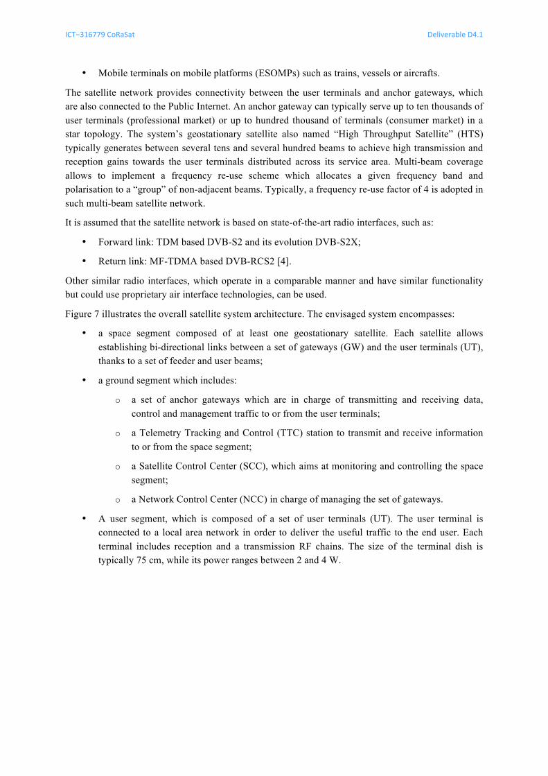
Figure 7 illustrates the overall satellite system architecture. The envisaged system encompasses:
• a space segment composed of at least one geostationary satellite. Each satellite allows establishing bi-directional links between a set of gateways (GW) and the user terminals (UT), thanks to a set of feeder and user beams;
• a ground segment which includes:
o a set of anchor gateways which are in charge of transmitting and receiving data, control and management traffic to or from the user terminals;
o a Telemetry Tracking and Control (TTC) station to transmit and receive information to or from the space segment;
o a Satellite Control Center (SCC), which aims at monitoring and controlling the space segment;
o a Network Control Center (NCC) in charge of managing the set of gateways.
• A user segment, which is composed of a set of user terminals (UT). The user terminal is connected to a local area network in order to deliver the useful traffic to the end user. Each terminal includes reception and a transmission RF chains. The size of the terminal dish is typically 75 cm, while its power ranges between 2 and 4 W.
ICT−316779 CoRaSat Deliverable D4.1
Release 1.0 pag. 20 of 50
Figure 7 - Overall top level satellite network architecture environment for an FSS satellite based broadband
access network
The network connecting the anchor GWs and the user terminals follows a star topology. A backbone network, which is not part of the access network, is in charge of interconnecting the SCC, the NCC, the GWs, the TTC and the Internet Service Providers (ISPs), namely to convey management and control traffics.
A forward (respectively, return) link is divided into a feeder (respectively a user) uplink and a user (respectively, feeder) downlink.
We consider 2 possible frequency plans based on a 4-color scheme. It should be noted that the frequency plan defined as baseline is the proposed usage frequency plan within CORASAT, reusing fully the available spectrum for scenario B and C for FSS terminal link applications. An alternative plan is proposed in case the usage of the scenario C band [27.5-29.5GHz] would reveal itself to be not feasible because of the regulatory context of a specific country. On a system level perspective it is in principle possible to mix the different frequency allocation schemes. The signal routing onboard the satellite and the capabilities of the gateways (GW) allow to segregate the satellite frequency plan according to the regulatory context on the ground.
A nominal frequency plan is illustrated in Figure 8:
• The user downlink is assigned the exclusive FSS band (namely [19.7 – 20.2] GHz) and a portion of the Ka-band spectrum primarily shared with BSS feeders (namely [17.3 – 17.7] GHz) and FS (namely [17.7 – 19.7] GHz). Thus the frequency plan assigned to the user downlink features 2.9 GHz of spectrum on two orthogonal circular polarisation. This corresponds to a 1.4 GHz spectrum allocation per beam, according to a regular four-color scheme (including a frequency guard band between 18.7 and 18.8 GHz). This enables an "increase" of the useful spectrum by 5.6 (= 1.4/0.25 GHz) with respect to systems operating in the exclusive FSS band only.
ICT−316779 CoRaSat Deliverable D4.1
Release 1.0 pag. 21 of 50
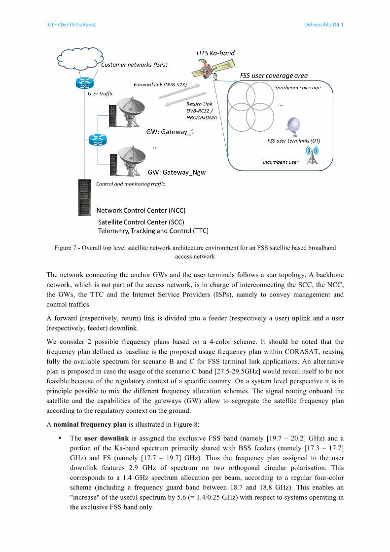
• Regarding the user uplink, the system uses the exclusive FSS band (namely [29.5 - 30] GHz) as well as the band [27.5 – 29.5] GHz shared with FS. Thus the frequency plan assigned to the user downlink features 2.5 GHz of spectrum on two orthogonal circular polarisations. This corresponds to a 1.25 GHz spectrum allocation per beam, according to a regular four-color scheme. This enables an "increase" of the useful spectrum by 5 (= 1.25/0.25 GHz) with respect to systems operating in the exclusive FSS band only.
Figure 8 - Nominal frequency plan for the FSS satellite system
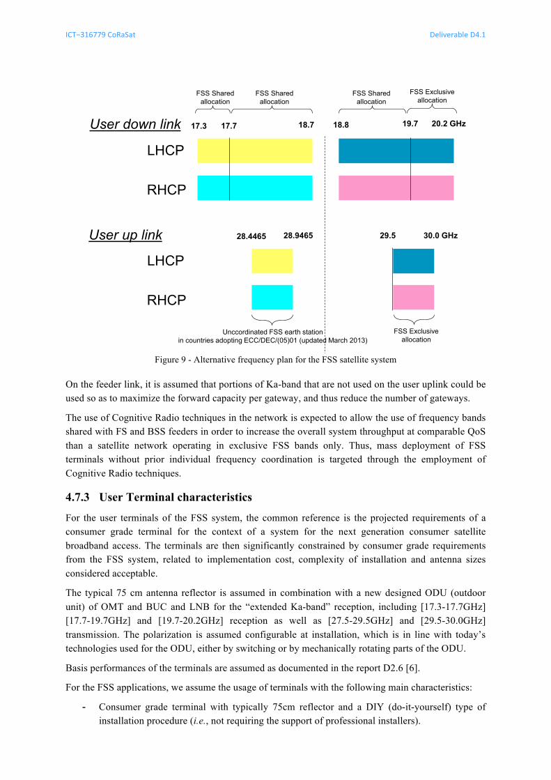
An alternative frequency plan illustrated in Figure 9:
• The user downlink is assigned the exclusive FSS band (namely [19.7 – 20.2] GHz) but also a portion of the Ka-band spectrum primarily shared with BSS feeders (namely [17.3 – 17.7] GHz) and FS (namely [17.7 – 19.7] GHz). Thus the frequency plan assigned to the user downlink features 2.9 GHz of spectrum on two orthogonal circular polarisation. This corresponds to a 1,4 GHz spectrum allocation per beam, according to a regular four-color scheme (including a frequency guard band between 18.7 GHz and 18.8 GHz). This enables an "increase" of the useful spectrum by 5.6 (= 1.4/0.25 GHz) with respect to systems operating in the exclusive FSS band only.
• Regarding the user uplink, the system uses the exclusive FSS band (namely [29.5 - 30] GHz) as well as the band [28.4465 – 28.9465] GHz shared with FS. Thus the frequency plan assigned to the user downlink features 1 GHz of spectrum on two orthogonal circular polarisation. This corresponds to a 500 MHz spectrum allocation per beam, according to a regular four-color scheme. This enables an "increase" of the useful spectrum by 2 (= 1/0.5 GHz) with respect to systems operating in the exclusive FSS band only.
ICT−316779 CoRaSat Deliverable D4.1
Release 1.0 pag. 22 of 50
Figure 9 - Alternative frequency plan for the FSS satellite system
On the feeder link, it is assumed that portions of Ka-band that are not used on the user uplink could be used so as to maximize the forward capacity per gateway, and thus reduce the number of gateways.
The use of Cognitive Radio techniques in the network is expected to allow the use of frequency bands shared with FS and BSS feeders in order to increase the overall system throughput at comparable QoS than a satellite network operating in exclusive FSS bands only. Thus, mass deployment of FSS terminals without prior individual frequency coordination is targeted through the employment of Cognitive Radio techniques.
4.7.3 User Terminal characteristics
For the user terminals of the FSS system, the common reference is the projected requirements of a consumer grade terminal for the context of a system for the next generation consumer satellite broadband access. The terminals are then significantly constrained by consumer grade requirements from the FSS system, related to implementation cost, complexity of installation and antenna sizes considered acceptable.
The typical 75 cm antenna reflector is assumed in combination with a new designed ODU (outdoor unit) of OMT and BUC and LNB for the “extended Ka-band” reception, including [17.3-17.7GHz] [17.7-19.7GHz] and [19.7-20.2GHz] reception as well as [27.5-29.5GHz] and [29.5-30.0GHz] transmission. The polarization is assumed configurable at installation, which is in line with today’s technologies used for the ODU, either by switching or by mechanically rotating parts of the ODU.
Basis performances of the terminals are assumed as documented in the report D2.6 [6].
For the FSS applications, we assume the usage of terminals with the following main characteristics:
- Consumer grade terminal with typically 75cm reflector and a DIY (do-it-yourself) type of installation procedure (i.e., not requiring the support of professional installers).
LHCP
RHCP
17.3 20.2 GHz18.818.7
LHCP
RHCP
30.0 GHz29.5
19.7
FSS Exclusiveallocation
17.7
FSS Exclusiveallocation
User up link
User down link
FSS Shared allocation
FSS Shared allocation
FSS Shared allocation
Unccordinated FSS earth stationin countries adopting ECC/DEC/(05)01 (updated March 2013)
28.4465 28.9465
ICT−316779 CoRaSat Deliverable D4.1
Release 1.0 pag. 23 of 50
- A bi-directional satellite modem with access to the satellite network defined in the previous section and the usage of the frequency bands in the defined ranges [27.5-30.0GHz] transmit and [17.3-20.2GHz] receive bands, subdivided into sub-bands as defined in the following.
- IP access to customer equipment with a quality of service segregation in the terminals to allow for access through different logical service classes and separate the best effort traffic from the priority effort along several levels of QoS classes.
- A control plane that keeps constantly access to the control commands form the gateway and maintains the network in a centrally controlled mode. All transmit and receive spectrum access at the terminal side is controlled from the centralized network control center (NCC).
For the ESOMP reference case, the antenna configuration is assumed to be auto tracking and steerable outside the cognitive radio context. The used receive and transmit frequency bands are also in this case controlled fully from the centralized network control center.
The user terminal is considered as a device that is embedded in an overall system layout with the NCC in control of the user terminals physical layer configurations through a control channel. This is performed by relying on dedicated defined “home default” configurations to gain access to the NCC control messages under all circumstances of reception conditions.
The default home transponder would be required to maintain access to the NCC when local interference on the NCC channel occurs on the forward link.
From the NCC control messages the terminals access the forward and return link capacity and also control their power and bandwidth allocation settings in a fully centralized manner.
The NCC control is therefore capable of allocating the resources on a network basis and can apply as required interference mitigation techniques in case a local interference is occurring.
The terminal uses for the detection of the forward link signal its built-in signal quality detection mechanisms.
These include the following elements:
- Signal to noise ratio estimation in a combined manner on the signal pilots and data (Es/N0)
- Signal to distortion estimation (based on the NODE algorithm for noise and distortion estimation) (C/D)
- Signal power estimation (C0)
- Noise power estimation in band and out of band of the received signal bandwidth (N0)
The user terminal adapts to the receive and transmit conditions that are defined by the NCC and reports over the control channel all possible measurements to the NCC for the purpose of network continuous monitoring.
In the current setup, we assume that these are based on the existing RF reception chain. A “next generation terminals” would be able to rely on techniques that are capable of using additional reception chains.
Therefore for the near term, we are considering the signal quality indicators, which also replying on estimations that are performed partially already in the process of the signal reception.
ICT−316779 CoRaSat Deliverable D4.1
Release 1.0 pag. 24 of 50
4.7.4 Network Control Center (NCC) definition
These parameters are used as a basis for the NCC to control and evaluate the reception quality of each terminal. In the context of this system, as described in D3.4, we intend to use these parameters to evaluate the reception conditions at each terminal’s location. For this the NCC implements a long-term perspective of the network configuration and monitors each terminal’s signal quality indicators.
The terminal can therefore use its signal quality indicators as tool to evaluate the overall network interference conditions.
The NCC evaluates the terminals in-band signal quality indicators as well as the out-of-band signal quality indicators that can be used in combination with a specific sensing technique, such as Energy Detection (ED) and Cyclostationary Feature detection (CC), as proposed here above.
The evaluation of the signal quality at reception of each terminal in the network is evaluated at the NCC level and treated to decide on whether a possible interference context is possible at each terminal location.
This is performed on a regular basis at the NCC level and subsequent decisions on the affectation of the terminal to specific frequency pools are made.
On the return link (covering scenario C), the NCC also takes the database input into account for each terminal position and processes the
The details of the NCC decision algorithm is defined and specified in the context of the work in D4.3.
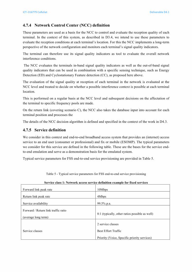
4.7.5 Service definition
We consider in this context and end-to-end broadband access system that provides an (internet) access service to an end user (consumer or professional) and fix or mobile (ESOMP). The typical parameters we consider for this service are defined in the following table. These are the bases for the service end-to-end emulation and serve as a demonstration basis for the emulated system.
Typical service parameters for FSS end-to-end service provisioning are provided in Table 5.
Table 5 - Typical service parameters for FSS end-to-end service provisioning
Service class 1: Network access service definition example for fixed services
Forward link peak rate 10Mbps
Return link peak rate 4Mbps
Service availability 99.5% p.a.
Forward / Return link traffic ratio
(average long term) 8:1 (typically, other ratios possible as well)
Service classes
2 service classes
Best Effort Traffic
Priority (Voice, Specific priority services)
ICT−316779 CoRaSat Deliverable D4.1
Release 1.0 pag. 25 of 50
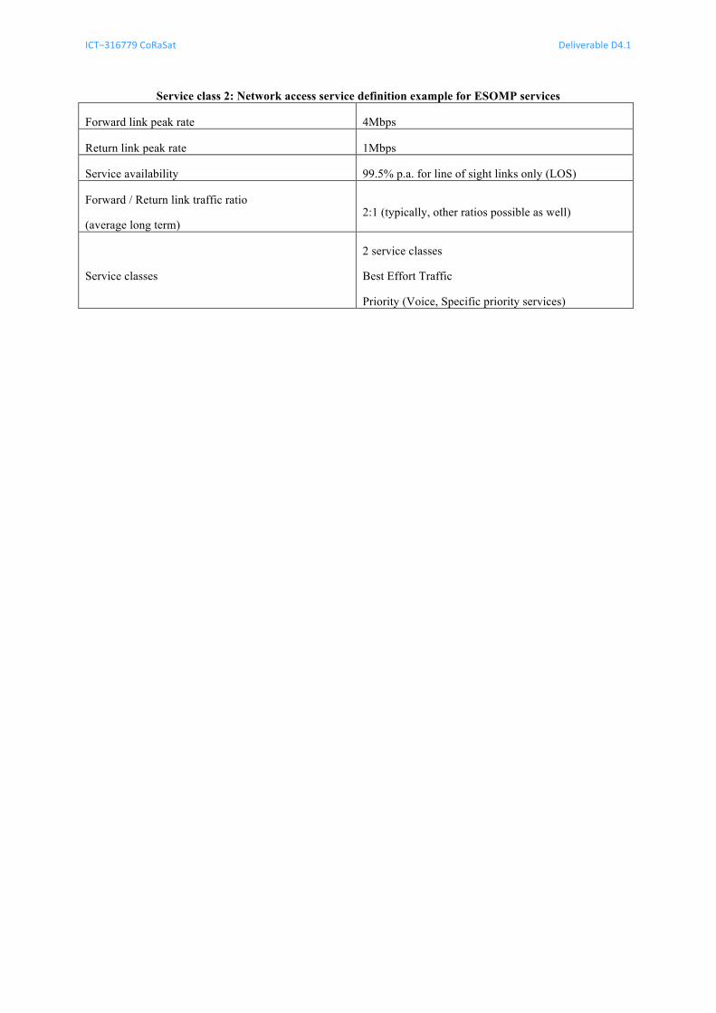
Service class 2: Network access service definition example for ESOMP services
Forward link peak rate 4Mbps
Return link peak rate 1Mbps
Service availability 99.5% p.a. for line of sight links only (LOS)
Forward / Return link traffic ratio
(average long term) 2:1 (typically, other ratios possible as well)
Service classes
2 service classes
Best Effort Traffic
Priority (Voice, Specific priority services)
ICT−316779 CoRaSat Deliverable D4.1
Release 1.0 pag. 26 of 50
5 US E CA S E S This chapter outlines the use cases that are to be emulated in the test testup in the lab and demonstrated to the end user. The use cases include the specific situations which occur under the operation of the two networks that share the same frequency bands.
We distinguish between different events and situations depending on the setup of the terminals and the environment of the FS links.
• Installation and commissioning of FSS terminals in presence of FS links
• Operation of FSS terminals with known FS link environment
• Operation of FSS terminals with unknown or changing FS link environment
• ESOMP terminal operation in FS link environment
• ESOMP terminal commissioning
For these specific use cases considered we can define the related demonstration cases and how to address the demonstration of the overall systems requirements in each case.
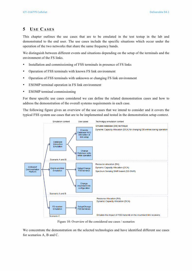
The following figure gives an overview of the use cases that we intend to consider and it covers the typical FSS system use cases that are to be implemented and tested in the demonstration setup context.
Figure 10: Overview of the considered use cases / scenarios
We concentrate the demonstration on the selected technologies and have identified different use cases for scenarios A, B and C.
ICT−316779 CoRaSat Deliverable D4.1
Release 1.0 pag. 27 of 50
Database interaction emulation (scenario A, B) 5.1Emulation of the database to NCC interaction:
A first use case is the database interaction is verified through a demonstration setup in an environment with incumbent user transmissions. The setup foresees to verify the NCC interaction to the database and the correct interpretation of the database information to allocate forward link and return link capacity to the terminals.
A second use case consists of changing the database entries and the incumbent user data and verify that the database to NCC interaction can work by adapting the parameters of the transmission on the forward link and the return link to all the terminals in the network.
End-to-end link emulation (scenario A, B) 5.2Emulation of the end-to-end link service quality over different scenarios
The emulation of the end to end links verifies the quality of service (QoS) delivered to the end users in terms of throughput and link robustness (margin, availability).
The use case of changing and provisioning a service to an FSS terminal is tested under the constraints of the incumbent frequency user in scenarios A, B (forward link) and C (return link).
FS receiver emulation (scenario C) 5.3Within the context of the return link, scenario C, the impact of the transmissions onto the receivers deployed in the scenario C case [27.5-29.5GHz] is evaluated. This entails the measurement of the defined performance indication in form of received interference power at the terrestrial Fix Service (FS) receiver input. The deployment of multiple FSS satellite terminals transmitting within the vicinity of the FS receiver is emulated and the interference is measured at the FS receiver input.
The applied performance indications in this use case are the limited interference measured at the FS link interference input and the FSS terminal service delivery at any location within the close vicinity of the FS link receiver.
FSS installation and commissioning 5.4The FSS installation and commissioning test includes the assumption that a new FSS terminal is installed in the FSS network and may utilize the spectrum allocations under the scenarios A and B in reception and C in transmission. The overall spectrum utilization depends then on the local interference and cognitive zones with respect to the terminal location of installation.
This use case foresees the terminal logon to the FSS network and the coordinated centralized network capability to assign the terminal capacity to the area required by the system.
This FSS installation is performed under a specific interference environment of the FSS terminal and the ability of the FSS terminal and system to configure correctly is demonstrated with this use case.
FSS terminal operation while changes to FS link parameters occur 5.5This use case foresees the change of power or symbol rate of the FS link or of the frequency occupation of the main system. Under different change conditions the FSS terminal should react to the changing FS link conditions (or BSS configuration changes). The configuration change of the incumbent user is taken into account by the FSS system and a reconfiguration of its capacity allocation is performed.
ICT−316779 CoRaSat Deliverable D4.1
Release 1.0 pag. 28 of 50
FSS terminal operation with FS link setup 5.6This use case foresees a normal network operation and the setup of an FS link under an existing FSS network operation.
The incumbent system can change and a new FS link is configured or the power or frequency allocation of the FS link is changed.
The impact on the FSS satellite system is that it experiences a potential increase in interference in a number of terminal locations.
FSS terminal operation in unknown environment 5.7For this scenario we assume that the FSS terminal is installed in a context where the interference environment from scenario A or B is unknown. This can be related to the fact that the database for this context is incomplete or is non-existing at all. In this case we rely on the sensing and resource allocation to work in a blind manner so that the system can perform a capacity allocation even if the database information is missing.
ICT−316779 CoRaSat Deliverable D4.1
Release 1.0 pag. 29 of 50
6 TA R G E T PE R F O R M A N C E IN D I C A T O R S For the performance evaluation of the end-to-end services, it is foreseen to measure the parameters that are defined as KPIs in the context of this project. Different classes of KPIs are measured:
1. At system level, the overall average throughput is evaluated of the end-to-end system
2. At link level per terminal, the availability of the throughput and service quality is evaluated according to the service definitions (forward and return link throughput and error rate targets)
3. At incumbent user level the measured performance indicator is the increase in noise floor and is measured over the noise and interference power density at the incumbent user receivers.
In CoRaSat Deliverable D3.1 [7], Key Performance Indicators (KPIs) in the context of the CoRaSat project were defined. These KPIs define the overall system performance as joint usage of the spectrum by the incumbent and cognitive users. These system-level KPIs refer to those parameters that among others allow comparing and selecting different techniques based on their overall performance. The three system KPIs considered are:
1. System Capacity, measured in average forward and return link efficiency (#1)
2. Service availability over coverage and per time (fading), measured as service throughput on forward and return link under no fading and fading conditions for each link / terminal (#2)
3. Impact on incumbent system, measured as total interference power density at the incumbent user receiver antenna input (compared to noise floor received) (#3)
Based on the defined KPIs as documented in D3.1, we emulate the following parameters as output parameters of the emulation setup:
1. System capacity metric (#1): The system capacity indicates the overall capacity that the system can support by taking into account both the incumbent and the cognitive systems. On one hand the cognitive techniques would allow to exploit those unused resources by the incumbent system thus increasing the overall system capacity. On the other hand the coexistence between incumbent and cognitive needs to be carefully designed for reducing the mutual interference that could result in low gain with respect to the system capacity. The system capacity is a good KPI because it allows comparing different cognitive techniques.
2. Service throughput and availability metric (#2): The geographical availability indicates the overall area where the cognitive system can be implemented subject to the constraints. This KPI is also a function of the incumbent system density, however, given a certain density, the higher is the geographical availability the higher is the impact of the cognitive systems to the final users. The geographical availability allows us to compare different cognitive techniques for each selected scenario with aim of selecting that technique that maximize the area in which the cognitive system can be used.
3. Impact on incumbent system metric (#3): Interference impact on the incumbent system in terms of additional noise floor or interference that the incumbent system has to take into account in the presence of the cognitive FSS satellite links (applicable for scenario C).
The system capacity and the geographical availability should be considered jointly when selecting the cognitive technique to be used in a certain scenario.
ICT−316779 CoRaSat Deliverable D4.1
Release 1.0 pag. 30 of 50
7 ST O R Y B O A R D O F TE S T C A S E S The test platform in the context of this study aims at demonstration of an end-to-end broadband access system with adequate adaptations for the operation under the considered scenarios A, B and C frequency bands.
The storyboard of the test platform therefore is setup of the definition of the use cases of the test platform that emulate “usage scenarios”, which reflect the events that can occur under the joint usage of the frequency band of the incumbent system in addition to the cognitive system. The joint usage is therefore illustrated by events that may occur in the joint platform usage scenario.
The considered usage scenarios in the storyboard aim to cover all practically possible KPIs and technologies that can be emulated in a lab setup.
The contexts evaluated are the following:
• Database interaction between the NCC and the database
• FSS end-to-end network emulation in an IF loopback (bi-directional)
• FS receiver emulation for the scenario C to evaluate the interference impact on the incumbent frequency users
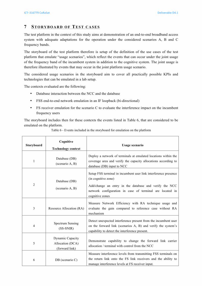
The storyboard includes then for these contexts the events listed in Table 6, that are considered to be emulated on the platform.
Table 6 - Events included in the storyboard for emulation on the platform
Storyboard Cognitive
Technology context Usage scenario
1 Database (DB) (scenario A, B)
Deploy a network of terminals at emulated locations within the coverage area and verify the capacity allocations according to database (DB) input to NCC
2 Database (DB)
(scenario A, B)
Setup FSS terminal in incumbent user link interference presence (in cognitive zone)
Add/change an entry in the database and verify the NCC network configuration in case of terminal are located in cognitive zones
3 Resource Allocation (RA) Measure Network Efficiency with RA technique usage and evaluate the gain compared to reference case without RA mechanism
4 Spectrum Sensing
(SS-SNIR)
Detect unexpected interference present from the incumbent user on the forward link (scenarios A, B) and verify the system’s capability to detect the interference present.
5 Dynamic Capacity Allocation (DCA)
(forward link)
Demonstrate capability to change the forward link carrier allocation / terminal with control from the NCC
6 DB (scenario C)
Measure interference levels from transmitting FSS terminals on the return link onto the FS link receivers and the ability to manage interference levels at FS receiver input.
ICT−316779 CoRaSat Deliverable D4.1
Release 1.0 pag. 31 of 50
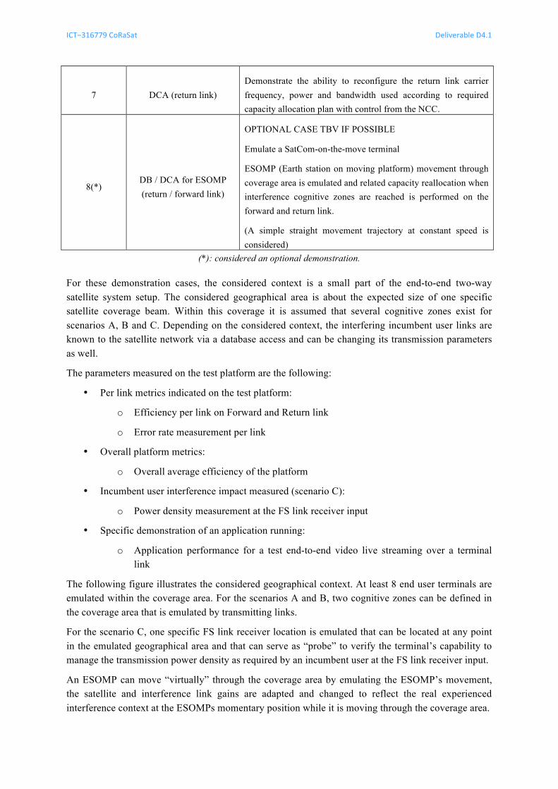
7 DCA (return link) Demonstrate the ability to reconfigure the return link carrier frequency, power and bandwidth used according to required capacity allocation plan with control from the NCC.
8(*) DB / DCA for ESOMP (return / forward link)
OPTIONAL CASE TBV IF POSSIBLE
Emulate a SatCom-on-the-move terminal
ESOMP (Earth station on moving platform) movement through coverage area is emulated and related capacity reallocation when interference cognitive zones are reached is performed on the forward and return link.
(A simple straight movement trajectory at constant speed is considered)
(*): considered an optional demonstration.
For these demonstration cases, the considered context is a small part of the end-to-end two-way satellite system setup. The considered geographical area is about the expected size of one specific satellite coverage beam. Within this coverage it is assumed that several cognitive zones exist for scenarios A, B and C. Depending on the considered context, the interfering incumbent user links are known to the satellite network via a database access and can be changing its transmission parameters as well.
The parameters measured on the test platform are the following:
• Per link metrics indicated on the test platform:
o Efficiency per link on Forward and Return link
o Error rate measurement per link
• Overall platform metrics:
o Overall average efficiency of the platform
• Incumbent user interference impact measured (scenario C):
o Power density measurement at the FS link receiver input
• Specific demonstration of an application running:
o Application performance for a test end-to-end video live streaming over a terminal link
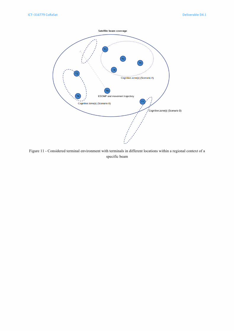
The following figure illustrates the considered geographical context. At least 8 end user terminals are emulated within the coverage area. For the scenarios A and B, two cognitive zones can be defined in the coverage area that is emulated by transmitting links.
For the scenario C, one specific FS link receiver location is emulated that can be located at any point in the emulated geographical area and that can serve as “probe” to verify the terminal’s capability to manage the transmission power density as required by an incumbent user at the FS link receiver input.
An ESOMP can move “virtually” through the coverage area by emulating the ESOMP’s movement, the satellite and interference link gains are adapted and changed to reflect the real experienced interference context at the ESOMPs momentary position while it is moving through the coverage area.
ICT−316779 CoRaSat Deliverable D4.1
Release 1.0 pag. 32 of 50
Figure 11 - Considered terminal environment with terminals in different locations within a regional context of a
specific beam
ICT−316779 CoRaSat Deliverable D4.1
Release 1.0 pag. 33 of 50
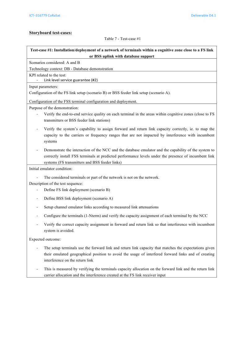
Storyboard test-cases: Table 7 - Test-case #1
Test-case #1: Installation/deployment of a network of terminals within a cognitive zone close to a FS link or BSS uplink with database support
Scenarios considered: A and B Technology context: DB - Database demonstration KPI related to the test:
-‐ Link level service guarantee (#2)
Input parameters: Configuration of the FS link setup (scenario B) or BSS feeder link setup (scenario A).
Configuration of the FSS terminal configuration and deployment. Purpose of the demonstration:
-‐ Verify the end-to-end service quality on each terminal in the areas within cognitive zones (close to FS transmitters or BSS feeder link stations)
-‐ Verify the system’s capability to assign forward and return link capacity correctly, ie. to map the capacity to the carriers or frequency ranges that are not impacted by interference with incumbent systems
-‐ Demonstrate the interaction of the NCC and the database emulator and the capability of the system to correctly install FSS terminals at predicted performance levels under the presence of incumbent link systems (FS transmitters and BSS feeder links)
Initial emulator condition:
-‐ The considered terminals or part of the network is not on the network. Description of the test sequence:
-‐ Define FS link deployment (scenario B)
-‐ Define BSS link deployment (scenario A)
-‐ Setup channel emulator links according to measured link attenuations
-‐ Configure the terminals (1-Nterm) and verify the capacity assignment of each terminal by the NCC
-‐ Verify the correct capacity assignment in forward and return link so that interference with incumbent system is avoided.
Expected outcome:
-‐ The setup terminals use the forward link and return link capacity that matches the expectations given their emulated geographical position to avoid the usage of interfered forward links and of creating interference on the return link
-‐ This is measured by verifying the terminals capacity allocation on the forward link and the return link carrier allocation and the interference created at the FS link receiver input
ICT−316779 CoRaSat Deliverable D4.1
Release 1.0 pag. 34 of 50
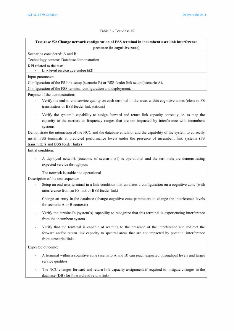
Table 8 - Test-case #2
Test-case #2: Change network configuration of FSS terminal in incumbent user link interference presence (in cognitive zone)
Scenarios considered: A and B Technology context: Database demonstration KPI related to the test:
-‐ Link level service guarantee (#2)
Input parameters: Configuration of the FS link setup (scenario B) or BSS feeder link setup (scenario A). Configuration of the FSS terminal configuration and deployment. Purpose of the demonstration:
-‐ Verify the end-to-end service quality on each terminal in the areas within cognitive zones (close to FS transmitters or BSS feeder link stations)
-‐ Verify the system’s capability to assign forward and return link capacity correctly, ie. to map the capacity to the carriers or frequency ranges that are not impacted by interference with incumbent systems
Demonstrate the interaction of the NCC and the database emulator and the capability of the system to correctly install FSS terminals at predicted performance levels under the presence of incumbent link systems (FS transmitters and BSS feeder links) Initial condition:
-‐ A deployed network (outcome of scenario #1) is operational and the terminals are demonstrating expected service throughputs
-‐ The network is stable and operational Description of the test sequence:
-‐ Setup an end user terminal in a link condition that emulates a configuration on a cognitive zone (with interference from an FS link or BSS feeder link)
-‐ Change an entry in the database (change cognitive zone parameters to change the interference levels for scenario A or B contexts)
-‐ Verify the terminal’s (system’s) capability to recognize that this terminal is experiencing interference from the incumbent system
-‐ Verify that the terminal is capable of reacting to the presence of the interference and redirect the forward and/or return link capacity to spectral areas that are not impacted by potential interference from terrestrial links
Expected outcome:
-‐ A terminal within a cognitive zone (scenario A and B) can reach expected throughput levels and target service qualities
-‐ The NCC changes forward and return link capacity assignment if required to mitigate changes in the database (DB) for forward and return links
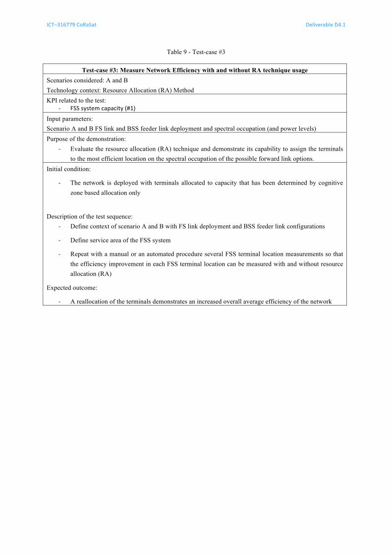
ICT−316779 CoRaSat Deliverable D4.1
Release 1.0 pag. 35 of 50
Table 9 - Test-case #3
Test-case #3: Measure Network Efficiency with and without RA technique usage Scenarios considered: A and B Technology context: Resource Allocation (RA) Method KPI related to the test:
-‐ FSS system capacity (#1)
Input parameters: Scenario A and B FS link and BSS feeder link deployment and spectral occupation (and power levels) Purpose of the demonstration:
-‐ Evaluate the resource allocation (RA) technique and demonstrate its capability to assign the terminals to the most efficient location on the spectral occupation of the possible forward link options.
Initial condition:
-‐ The network is deployed with terminals allocated to capacity that has been determined by cognitive zone based allocation only
Description of the test sequence:
-‐ Define context of scenario A and B with FS link deployment and BSS feeder link configurations
-‐ Define service area of the FSS system
-‐ Repeat with a manual or an automated procedure several FSS terminal location measurements so that the efficiency improvement in each FSS terminal location can be measured with and without resource allocation (RA)
Expected outcome:
-‐ A reallocation of the terminals demonstrates an increased overall average efficiency of the network
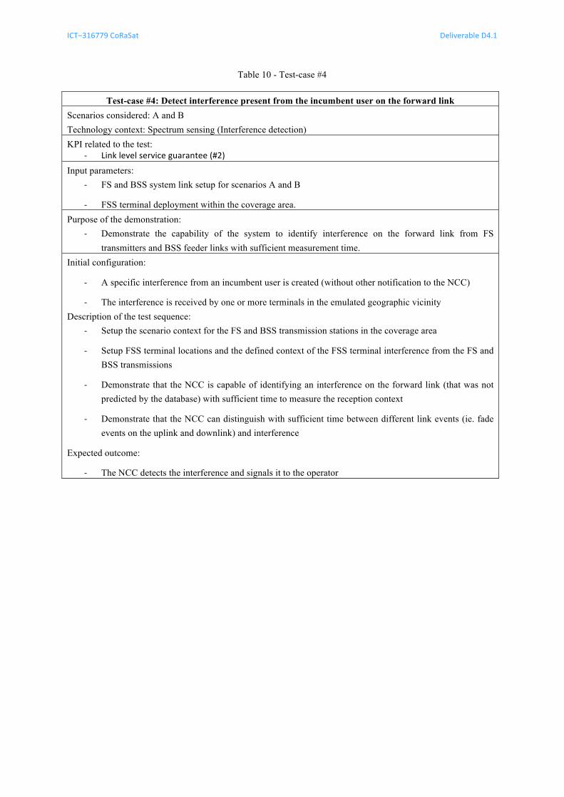
ICT−316779 CoRaSat Deliverable D4.1
Release 1.0 pag. 36 of 50
Table 10 - Test-case #4
Test-case #4: Detect interference present from the incumbent user on the forward link Scenarios considered: A and B Technology context: Spectrum sensing (Interference detection) KPI related to the test:
-‐ Link level service guarantee (#2)
Input parameters: -‐ FS and BSS system link setup for scenarios A and B
-‐ FSS terminal deployment within the coverage area. Purpose of the demonstration:
-‐ Demonstrate the capability of the system to identify interference on the forward link from FS transmitters and BSS feeder links with sufficient measurement time.
Initial configuration:
-‐ A specific interference from an incumbent user is created (without other notification to the NCC)
-‐ The interference is received by one or more terminals in the emulated geographic vicinity Description of the test sequence:
-‐ Setup the scenario context for the FS and BSS transmission stations in the coverage area
-‐ Setup FSS terminal locations and the defined context of the FSS terminal interference from the FS and BSS transmissions
-‐ Demonstrate that the NCC is capable of identifying an interference on the forward link (that was not predicted by the database) with sufficient time to measure the reception context
-‐ Demonstrate that the NCC can distinguish with sufficient time between different link events (ie. fade events on the uplink and downlink) and interference
Expected outcome:
-‐ The NCC detects the interference and signals it to the operator
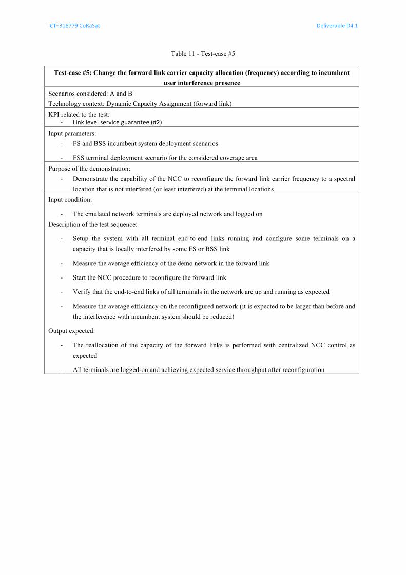
ICT−316779 CoRaSat Deliverable D4.1
Release 1.0 pag. 37 of 50
Table 11 - Test-case #5
Test-case #5: Change the forward link carrier capacity allocation (frequency) according to incumbent user interference presence
Scenarios considered: A and B Technology context: Dynamic Capacity Assignment (forward link) KPI related to the test:
-‐ Link level service guarantee (#2)
Input parameters: -‐ FS and BSS incumbent system deployment scenarios
-‐ FSS terminal deployment scenario for the considered coverage area Purpose of the demonstration:
-‐ Demonstrate the capability of the NCC to reconfigure the forward link carrier frequency to a spectral location that is not interfered (or least interfered) at the terminal locations
Input condition:
-‐ The emulated network terminals are deployed network and logged on Description of the test sequence:
-‐ Setup the system with all terminal end-to-end links running and configure some terminals on a capacity that is locally interfered by some FS or BSS link
-‐ Measure the average efficiency of the demo network in the forward link
-‐ Start the NCC procedure to reconfigure the forward link
-‐ Verify that the end-to-end links of all terminals in the network are up and running as expected
-‐ Measure the average efficiency on the reconfigured network (it is expected to be larger than before and the interference with incumbent system should be reduced)
Output expected:
-‐ The reallocation of the capacity of the forward links is performed with centralized NCC control as expected
-‐ All terminals are logged-on and achieving expected service throughput after reconfiguration
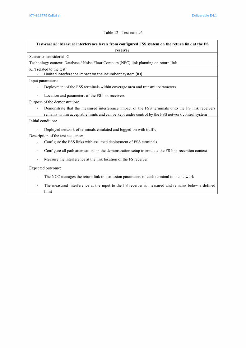
ICT−316779 CoRaSat Deliverable D4.1
Release 1.0 pag. 38 of 50
Table 12 - Test-case #6
Test-case #6: Measure interference levels from configured FSS system on the return link at the FS receiver
Scenarios considered: C Technology context: Database / Noise Floor Contours (NFC) link planning on return link KPI related to the test:
-‐ Limited interference impact on the incumbent system (#3)
Input parameters: -‐ Deployment of the FSS terminals within coverage area and transmit parameters
-‐ Location and parameters of the FS link receivers Purpose of the demonstration:
-‐ Demonstrate that the measured interference impact of the FSS terminals onto the FS link receivers remains within acceptable limits and can be kept under control by the FSS network control system
Initial condition:
-‐ Deployed network of terminals emulated and logged-on with traffic Description of the test sequence:
-‐ Configure the FSS links with assumed deployment of FSS terminals
-‐ Configure all path attenuations in the demonstration setup to emulate the FS link reception context
-‐ Measure the interference at the link location of the FS receiver
Expected outcome:
-‐ The NCC manages the return link transmission parameters of each terminal in the network
-‐ The measured interference at the input to the FS receiver is measured and remains below a defined limit
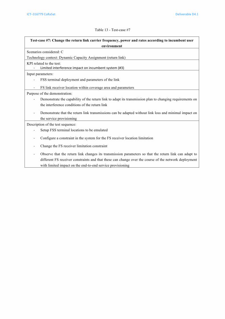
ICT−316779 CoRaSat Deliverable D4.1
Release 1.0 pag. 39 of 50
Table 13 - Test-case #7
Test-case #7: Change the return link carrier frequency, power and rates according to incumbent user environment
Scenarios considered: C Technology context: Dynamic Capacity Assignment (return link) KPI related to the test:
-‐ Limited interference impact on incumbent system (#3)
Input parameters: -‐ FSS terminal deployment and parameters of the link
-‐ FS link receiver location within coverage area and parameters Purpose of the demonstration:
-‐ Demonstrate the capability of the return link to adapt its transmission plan to changing requirements on the interference conditions of the return link
-‐ Demonstrate that the return link transmissions can be adapted without link loss and minimal impact on the service provisioning
Description of the test sequence: -‐ Setup FSS terminal locations to be emulated
-‐ Configure a constraint in the system for the FS receiver location limitation
-‐ Change the FS receiver limitation constraint
-‐ Observe that the return link changes its transmission parameters so that the return link can adapt to different FS receiver constraints and that these can change over the course of the network deployment with limited impact on the end-to-end service provisioning
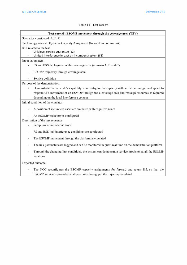
ICT−316779 CoRaSat Deliverable D4.1
Release 1.0 pag. 40 of 50
Table 14 - Test-case #8
Test-case #8: ESOMP movement through the coverage area (TBV) Scenarios considered: A, B, C Technology context: Dynamic Capacity Assignment (forward and return link) KPI related to the test:
-‐ Link level service guarantee (#2) -‐ Limited interference impact on incumbent system (#3)
Input parameters: -‐ FS and BSS deployment within coverage area (scenario A, B and C)
-‐ ESOMP trajectory through coverage area
-‐ Service definition Purpose of the demonstration:
-‐ Demonstrate the network’s capability to reconfigure the capacity with sufficient margin and speed to respond to a movement of an ESMOP through the a coverage area and reassign resources as required depending on the local interference context
Initial condition of the emulator:
-‐ A position of incumbent users are emulated with cognitive zones
-‐ An ESOMP trajectory is configured Description of the test sequence:
-‐ Setup link at initial conditions
-‐ FS and BSS link interference conditions are configured
-‐ The ESOMP movement through the platform is emulated
-‐ The link parameters are logged and can be monitored in quasi real time on the demonstration platform
-‐ Through the changing link conditions, the system can demonstrate service provision at all the ESOMP locations
Expected outcome:
-‐ The NCC reconfigures the ESOMP capacity assignments for forward and return link so that the ESOMP service is provided at all positions throughput the trajectory emulated
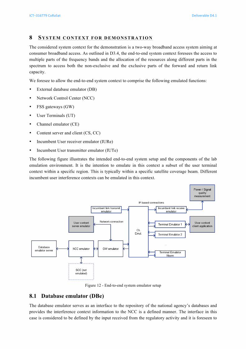
ICT−316779 CoRaSat Deliverable D4.1
Release 1.0 pag. 41 of 50
8 SY S T E M C O N T E X T F O R D E M O N S T R A T I O N The considered system context for the demonstration is a two-way broadband access system aiming at consumer broadband access. As outlined in D3.4, the end-to-end system context foresees the access to multiple parts of the frequency bands and the allocation of the resources along different parts in the spectrum to access both the non-exclusive and the exclusive parts of the forward and return link capacity.
We foresee to allow the end-to-end system context to comprise the following emulated functions:
• External database emulator (DB)
• Network Control Center (NCC)
• FSS gateways (GW)
• User Terminals (UT)
• Channel emulator (CE)
• Content server and client (CS, CC)
• Incumbent User receiver emulator (IURe)
• Incumbent User transmitter emulator (IUTe)
The following figure illustrates the intended end-to-end system setup and the components of the lab emulation environment. It is the intention to emulate in this context a subset of the user terminal context within a specific region. This is typically within a specific satellite coverage beam. Different incumbent user interference contexts can be emulated in this context.
Figure 12 - End-to-end system emulator setup
Database emulator (DBe) 8.1The database emulator serves as an interface to the repository of the national agency’s databases and provides the interference context information to the NCC is a defined manner. The interface in this case is considered to be defined by the input received from the regulatory activity and it is foreseen to
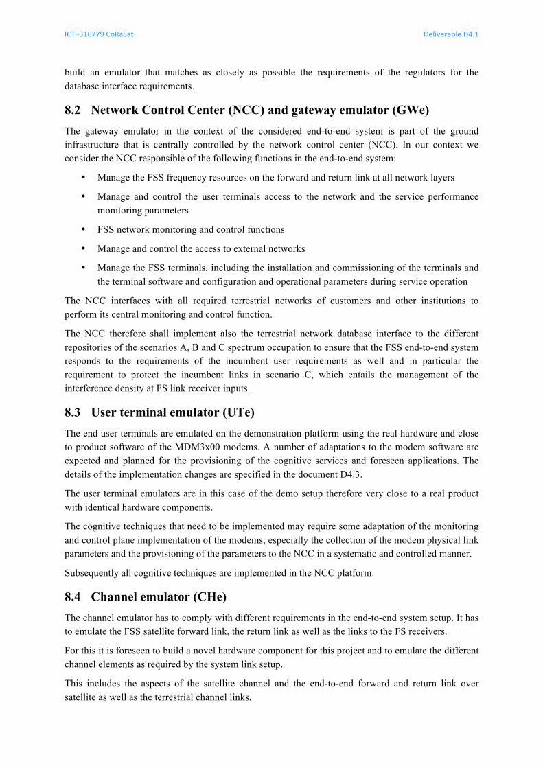
ICT−316779 CoRaSat Deliverable D4.1
Release 1.0 pag. 42 of 50
build an emulator that matches as closely as possible the requirements of the regulators for the database interface requirements.
Network Control Center (NCC) and gateway emulator (GWe) 8.2The gateway emulator in the context of the considered end-to-end system is part of the ground infrastructure that is centrally controlled by the network control center (NCC). In our context we consider the NCC responsible of the following functions in the end-to-end system:
• Manage the FSS frequency resources on the forward and return link at all network layers
• Manage and control the user terminals access to the network and the service performance monitoring parameters
• FSS network monitoring and control functions
• Manage and control the access to external networks
• Manage the FSS terminals, including the installation and commissioning of the terminals and the terminal software and configuration and operational parameters during service operation
The NCC interfaces with all required terrestrial networks of customers and other institutions to perform its central monitoring and control function.
The NCC therefore shall implement also the terrestrial network database interface to the different repositories of the scenarios A, B and C spectrum occupation to ensure that the FSS end-to-end system responds to the requirements of the incumbent user requirements as well and in particular the requirement to protect the incumbent links in scenario C, which entails the management of the interference density at FS link receiver inputs.
User terminal emulator (UTe) 8.3The end user terminals are emulated on the demonstration platform using the real hardware and close to product software of the MDM3x00 modems. A number of adaptations to the modem software are expected and planned for the provisioning of the cognitive services and foreseen applications. The details of the implementation changes are specified in the document D4.3.
The user terminal emulators are in this case of the demo setup therefore very close to a real product with identical hardware components.
The cognitive techniques that need to be implemented may require some adaptation of the monitoring and control plane implementation of the modems, especially the collection of the modem physical link parameters and the provisioning of the parameters to the NCC in a systematic and controlled manner.
Subsequently all cognitive techniques are implemented in the NCC platform.
Channel emulator (CHe) 8.4The channel emulator has to comply with different requirements in the end-to-end system setup. It has to emulate the FSS satellite forward link, the return link as well as the links to the FS receivers.
For this it is foreseen to build a novel hardware component for this project and to emulate the different channel elements as required by the system link setup.
This includes the aspects of the satellite channel and the end-to-end forward and return link over satellite as well as the terrestrial channel links.
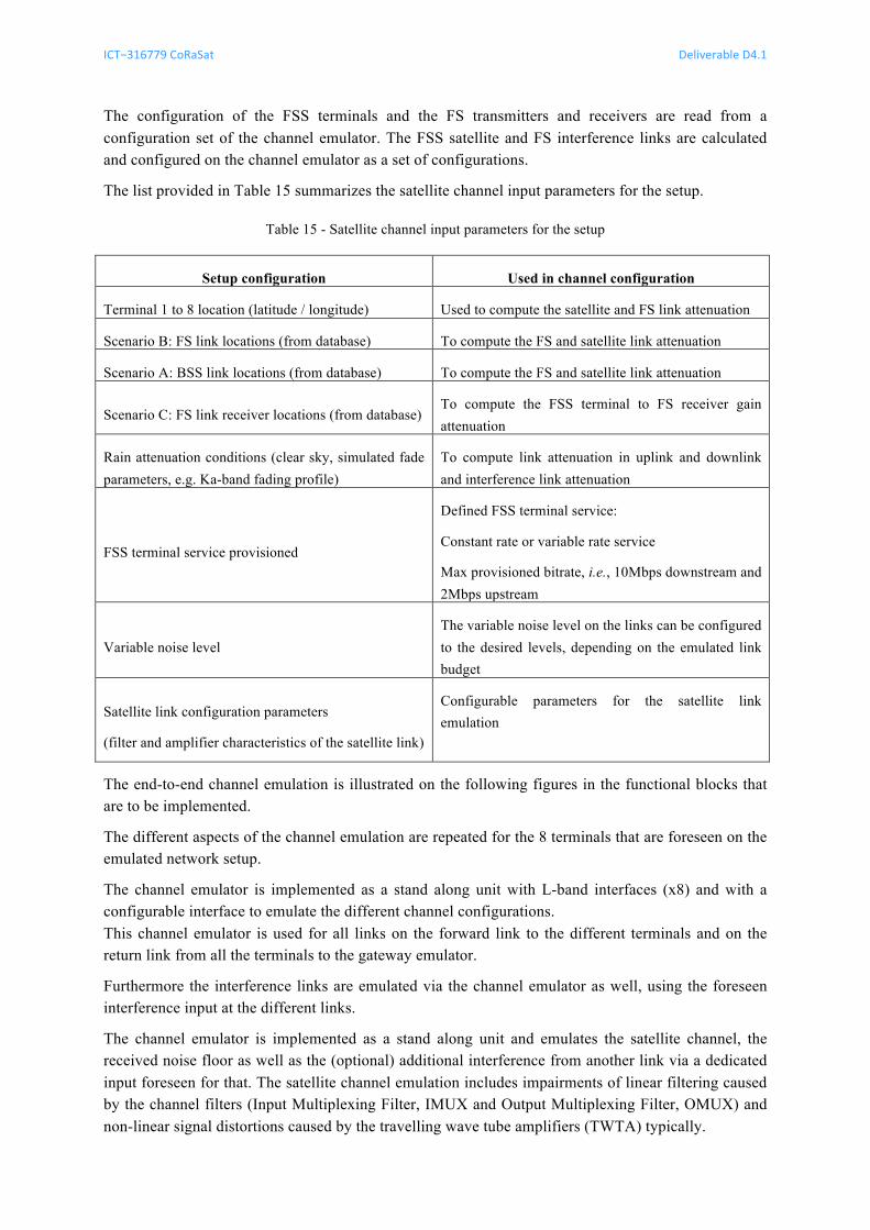
ICT−316779 CoRaSat Deliverable D4.1
Release 1.0 pag. 43 of 50
The configuration of the FSS terminals and the FS transmitters and receivers are read from a configuration set of the channel emulator. The FSS satellite and FS interference links are calculated and configured on the channel emulator as a set of configurations.
The list provided in Table 15 summarizes the satellite channel input parameters for the setup.
Table 15 - Satellite channel input parameters for the setup
Setup configuration Used in channel configuration
Terminal 1 to 8 location (latitude / longitude) Used to compute the satellite and FS link attenuation
Scenario B: FS link locations (from database) To compute the FS and satellite link attenuation
Scenario A: BSS link locations (from database) To compute the FS and satellite link attenuation
Scenario C: FS link receiver locations (from database) To compute the FSS terminal to FS receiver gain attenuation
Rain attenuation conditions (clear sky, simulated fade parameters, e.g. Ka-band fading profile)
To compute link attenuation in uplink and downlink and interference link attenuation
FSS terminal service provisioned
Defined FSS terminal service:
Constant rate or variable rate service
Max provisioned bitrate, i.e., 10Mbps downstream and 2Mbps upstream
Variable noise level The variable noise level on the links can be configured to the desired levels, depending on the emulated link budget
Satellite link configuration parameters
(filter and amplifier characteristics of the satellite link)
Configurable parameters for the satellite link emulation
The end-to-end channel emulation is illustrated on the following figures in the functional blocks that are to be implemented.
The different aspects of the channel emulation are repeated for the 8 terminals that are foreseen on the emulated network setup.
The channel emulator is implemented as a stand along unit with L-band interfaces (x8) and with a configurable interface to emulate the different channel configurations. This channel emulator is used for all links on the forward link to the different terminals and on the return link from all the terminals to the gateway emulator.
Furthermore the interference links are emulated via the channel emulator as well, using the foreseen interference input at the different links.
The channel emulator is implemented as a stand along unit and emulates the satellite channel, the received noise floor as well as the (optional) additional interference from another link via a dedicated input foreseen for that. The satellite channel emulation includes impairments of linear filtering caused by the channel filters (Input Multiplexing Filter, IMUX and Output Multiplexing Filter, OMUX) and non-linear signal distortions caused by the travelling wave tube amplifiers (TWTA) typically.
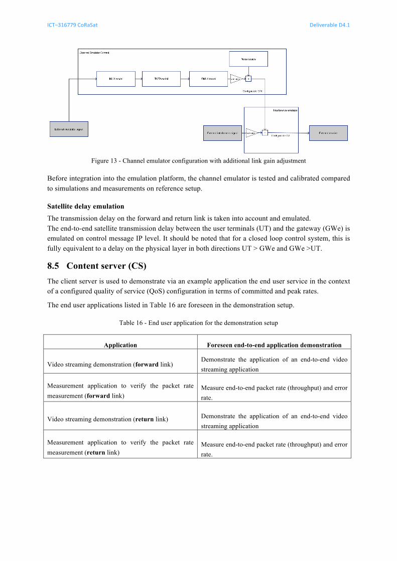
ICT−316779 CoRaSat Deliverable D4.1
Release 1.0 pag. 44 of 50
Figure 13 - Channel emulator configuration with additional link gain adjustment
Before integration into the emulation platform, the channel emulator is tested and calibrated compared to simulations and measurements on reference setup.
Satellite delay emulation
The transmission delay on the forward and return link is taken into account and emulated. The end-to-end satellite transmission delay between the user terminals (UT) and the gateway (GWe) is emulated on control message IP level. It should be noted that for a closed loop control system, this is fully equivalent to a delay on the physical layer in both directions UT > GWe and GWe >UT.
Content server (CS) 8.5The client server is used to demonstrate via an example application the end user service in the context of a configured quality of service (QoS) configuration in terms of committed and peak rates.
The end user applications listed in Table 16 are foreseen in the demonstration setup.
Table 16 - End user application for the demonstration setup
Application Foreseen end-to-end application demonstration
Video streaming demonstration (forward link) Demonstrate the application of an end-to-end video streaming application
Measurement application to verify the packet rate measurement (forward link)
Measure end-to-end packet rate (throughput) and error rate.
Video streaming demonstration (return link) Demonstrate the application of an end-to-end video streaming application
Measurement application to verify the packet rate measurement (return link)
Measure end-to-end packet rate (throughput) and error rate.

ICT−316779 CoRaSat Deliverable D4.1
Release 1.0 pag. 45 of 50
Application content client (CC) 8.6The application client emulates the end-to-end application and is used to illustrate the quality of service (or quality of experience) in the presence of different emulated link interference conditions.
It is foreseen to emulate specifically applications that can measure the throughput and end-to-end error rate performance. The content client emulator interacts with the content server emulator (CSe) and provides a way to display the demonstration video streaming as well as measure the end-to-end packet throughput and error rate.
ICT−316779 CoRaSat Deliverable D4.1
Release 1.0 pag. 46 of 50
9 CO N C L U S I O N S A N D NE X T ST E P S We defined in this document a demonstration platform and the use cases to be considered in the context of the CoRaSat project. The demonstration platform foreseen is an IF loopback platform that includes a demonstration of an end-to-end service over a broadband access platform.
The demonstration foreseen focuses on the following aspects:
1. Demonstration of a broadband platform that is capable of managing forward and return link capacity in a fully centralized manner. The physical and MAC access layer capability to mitigate potential interference by changing capacity allocation of the terminals in the network in a centralized manner.
2. Demonstration of selected key technology aspects of the platform and the feasibility (proof of concept) of the techniques on the demonstration platform. This includes the proposed techniques related to database (DB), resource allocation (RA) and spectrum sensing (SS-SNIR).
3. Demonstration of the interference impact on the incumbent user. This includes the assessment of the maximal power allocation towards known fixed services (FS) receiver locations (for the context of scenario C).
For this context, we foresee to demonstrate fully the capability of the broadband access platform to interoperate with an external database and define configurations that are successfully avoiding interference on reception and respect applicable interference limits on transmission, while fully complying with a typical end-to-end service requirement. In addition the platform is capable of assessing the overall system capacity gains.
The details of the demonstration setup are specified in the document D4.2 test plan document and D4.3 test set implementation.
ICT−316779 CoRaSat Deliverable D4.1
Release 1.0 pag. 47 of 50
10 DE F I N I T I O N, SY M B O L S A N D AB B R E V I A T I O N S 2G Second Generation Mobile Communication 3G Third Generation Mobile Communication 3GPP Third Generation Partnership Project 4G Fourth Generation Mobile Communication BSM Broadband Satellite Multimedia CQI Channel Quality Information CR Cognitive Radio CS Compressive Sensing CSI Channel State Information CENELEC Centre for Electro Technical Standards DCA Dynamic Capacity Assignment/Allocation DoA Direction of Arrival DVB Digital Video Broadcasting DVB-H Digital Video Broadcasting - Handheld DVB-RCS Digital Video Broadcasting with Return Channel via Satellite DVB-S Digital Video Broadcasting via Satellite DVB-S2(X) DVB via Satellite version 2 (S2extensions) based on EN 302 307 ETSI European Telecommunications Standards Institute FC Fusion Center FS Fixed Service FSS Fixed Satellite System GWe Gateway emulator IA Interference Alignment IC Interference Cartography IDW Inverse Distance Weighted IMUX Input Multiplexing Filter IUT Incumbent User Terminal LRT Likelihood-Ratio Test LTE Long Term Evolution LTE-A LTE Advanced MAC Medium Access Control MIMO Multiple Input Multiple Output NCC Network Control Centre RA Resource Allocation
ICT−316779 CoRaSat Deliverable D4.1
Release 1.0 pag. 48 of 50
REM Radio Environment Map RCST RCS Terminal RF Radio Frequency RLC Radio Link Control RSS Received Signal Strength SCC Satellite Control Center SIN Satellite Interactive Network SS-ED Spectrum Sensing Energy Detection SS-CS Spectrum Sensing cyclo-stationary feature detection SS-SNIR Spectrum Sensing signal to noise and interference ratio based ToA Time of Arrival TWTA Travelling Wave Tube Amplifier UMTS Universal Mobile Telecommunication System UTRAN UMTS Terrestrial Radio Access Network UTe User terminal emulator
ICT−316779 CoRaSat Deliverable D4.1
Release 1.0 pag. 49 of 50
11 RE F E R E N C E S [1] Corasat (COgnitive RAdios for SATellite Communications), FP7 ICT STREP Grant
Agreement n. 316779, Annex I, Description of Work (DOW), 2012-06-29 [2] Corasat (COgnitive RAdios for SATellite Communications), FP7 ICT STREP Grant
Agreement n. 316779, D3.3 “Adaptation and Design of Cognitive Techniques for Satellite Communications,” 2014
[3] ETSI EN 302 307, Digital Video Broadcasting (DVB); Second generation framing structure, channel coding and modulation systems for Broadcasting, Interactive Services, News Gathering and other broadband satellite applications; Part 2: DVB-S2 Extensions (DVB-S2x) V1.1.1, October 2014.
[4] ETSI TS 101 545-1 V1.2.1 (2014-04) Digital Video Broadcasting (DVB); Second Generation DVB Interactive Satellite System (DVB-RCS2); Part 1: Overview and System Level specification, V1.2.1, April 2014.
[5] Corasat (COgnitive RAdios for SATellite Communications), FP7 ICT STREP Grant Agreement n. 316779, D2.4 “Service and Market Requirements,” 2013
[6] Corasat (COgnitive RAdios for SATellite Communications), FP7 ICT STREP Grant Agreement n. 316779, D2.6 “Technology Framework,” 2013
[7] Corasat (COgnitive RAdios for SATellite Communications), FP7 ICT STREP Grant Agreement n. 316779, D3.1 “Scenarios and Technical Requirements,” 2014

ICT−316779 CoRaSat Deliverable D4.1
Release 1.0 pag. 50 of 50
12 DO C U M E N T HI S T O R Y Rel. version Date Change Status Author 1 0 28/10/2014 First release to the European Commission NTC