Embed Size (px)
Citation preview

SRPE AASHTO Specifications
July 19 2013July 19, 2013
www.concrete-pipe.org
2Steel Ribbed HDPE= SRHDPE S
= SRPENow has AASHTO Design and ConstructionNow has AASHTO Design and Construction
Specifications for SRPE….
But wait there is more…
AASHTO Bridge Design Specs - Section 12• SRPE AASHTO MP 20-11 • Fiberglass Pipe ASTM D3262• Corrugated PP AASHTO MP 21
www.concrete-pipe.org
g

3
4

5SRPE Marketing

6SRPE Marketing
www.concrete-pipe.org

7SRPE MarketingMetalMetal
+PlasticPlastic
= Strength and Durability“Finally a drainage product that isFinally a drainage product that is engineered for service and long life!”
Two dissimilar materials utilized in a composite pipe structure will interact p p pwith each other once in an installed condition – what will happen???
www.concrete-pipe.org

8SRPE Questions
Is Local Buckling Equation Applicable?pp
www.concrete-pipe.orgwww.concrete-pipe.org

9SRPE Questions
What about the steel?
f
Compressive Stresses - Yes
Bending Stresses - No
www.concrete-pipe.orgwww.concrete-pipe.org

10
Design ConsiderationsL l b kli ti h ld b• Local buckling equation should be verified for metal constrained by polyethylenepolyethylene
• Global buckling equation should be verified for a non uniformverified for a non-uniform steel/polyethylene profileBending stresses should be• Bending stresses should be considered
www.concrete-pipe.orgwww.concrete-pipe.org

11
Design IssuesC l l ti h ld b i d b• Calculations should be reviewed by Engineer to determine that appropriate allowable steel stressesappropriate allowable steel stresses were used.
• Fatigue may need to be considered if• Fatigue may need to be considered if under a shallow installation using really high allowable stress levelsreally high allowable stress levels.
www.concrete-pipe.orgwww.concrete-pipe.org
12
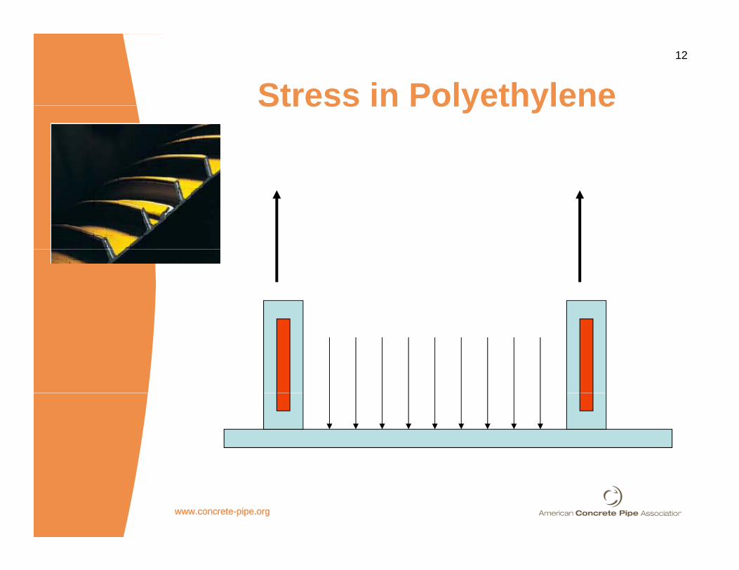
Stress in PolyethyleneStress in Polyethylene
www.concrete-pipe.orgwww.concrete-pipe.org

13
AASHTO Bridge Design Section 12 12.7.2.1 – Section Properties
Dimensions and properties of pipe cross-sections; minimum seam strength; mechanical and chemical requirements for aluminum corrugated and steel corrugated pipe and pipe-arch sections; and aluminum and steel corrugated structural plate pipe, pipe-arch, and arch sections, may be taken as given in Appendix A12. Dimensions, properties of pipe cross-sections, and material properties for steel-reinforced thermoplastic culverts shall be provided by the pipe manufacturer.(emphasis added)
www.concrete-pipe.org

14
AASHTO Bridge Design Section 12 C12.7.2.1 - commentary
Steel-reinforced thermoplastic culverts are pipe sections in which the main load-carrying members are steel ribs encapsulated by thermoplastic material that may brace the ribs from distortion and buckling. This composite system should be evaluated independently for each manufacturer’s pipe system. Designers should obtain the required mechanical properties directly from the pipe manufacturer to determine fill heights. g(emphasis added)
www.concrete-pipe.org
15
AASHTO Bridge Design Section 12
www.concrete-pipe.org

16
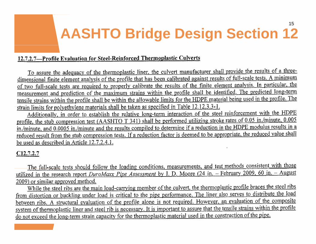
AASHTO Bridge Design Section 12 C12.7.2.7 - commentary
While the steel ribs are the main load carrying member of the culvert, the thermoplastic profile braces the steel ribs from distortion or buckling under load is critical to the pipe performance. The liner also serves to distribute the load between ribs. A structural evaluation of the profile alone is not required. However, an evaluation of the composite system of thermoplastic liner and steel rib is necessary. It is important to assure that the tensile strains within the profile do not exceed the long-term strain capacity for the thermoplastic material used in the construction of the pipe.p p(emphasis added)
www.concrete-pipe.org

17
AASHTO Bridge Construction Specs
26.1.1 DescriptionThis work shall consist of furnishing, gfabricating, installing, and inspecting metal pipe, structural plate metal pipe, arches pipe arches box structures andarches, pipe arches, box structures, and deep corrugated structures, and steel-reinforced thermoplastic pipe in conformance with these Specifications and the details shown in the contract documentsdocuments.
www.concrete-pipe.org
18
AASHTO Bridge Construction Specs
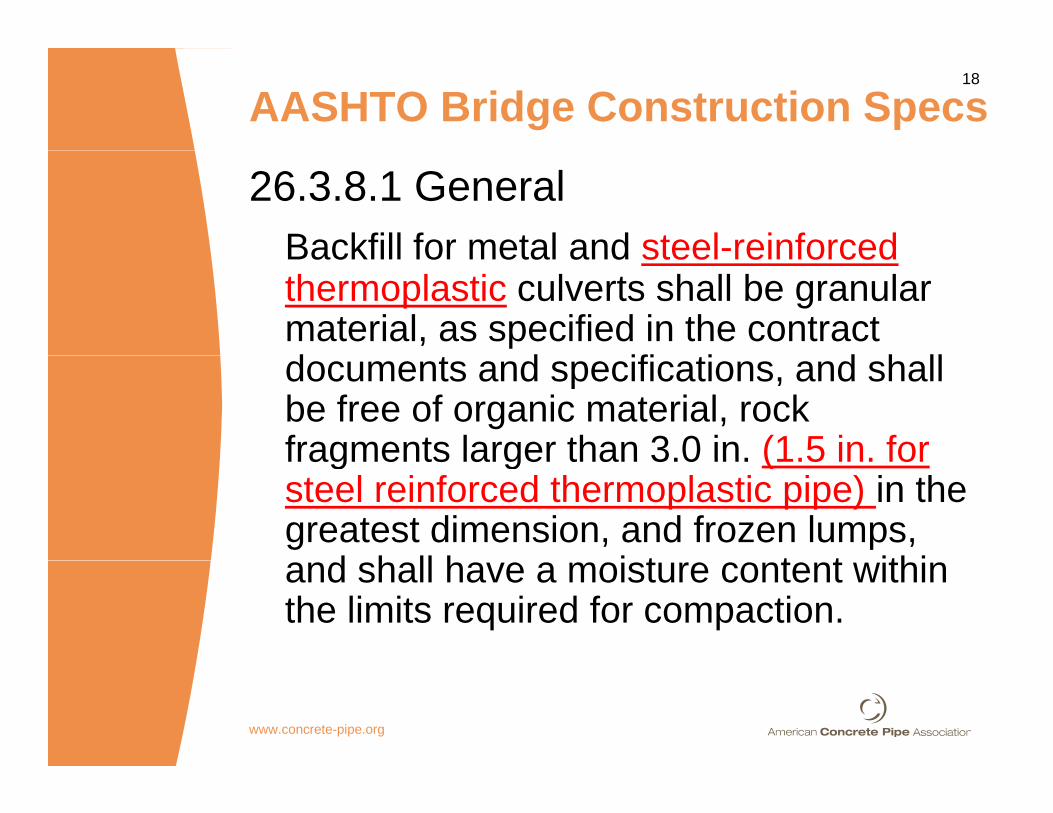
26.3.8.1 GeneralBackfill for metal and steel-reinforcedBackfill for metal and steel reinforced thermoplastic culverts shall be granular material, as specified in the contract d t d ifi ti d h lldocuments and specifications, and shall be free of organic material, rock fragments larger than 3.0 in. (1.5 in. forfragments larger than 3.0 in. (1.5 in. for steel reinforced thermoplastic pipe) in the greatest dimension, and frozen lumps,
d h ll h i t t t ithiand shall have a moisture content within the limits required for compaction.
www.concrete-pipe.org

19
AASHTO Bridge Construction Specs
26.3.9—Steel-Reinforced Thermoplastic CulvertsSteel-reinforced thermoplastic culverts shall conform to the requirements of AASHTO MP 20.(emphasis added)
AASHTO MP 20-11 has been approved for 12”-60”
www.concrete-pipe.org

20AASHTO Section 26 Metal - Joints
26.4.2.5—Steel Reinforced Thermoplastic Culvert JointsJoints for steel reinforced thermoplastic pipe shall comply with the details shown in the contract drawings and on the approved working drawings. Each joint shall be sealed to prevent infiltration of soil (soiltight), fines (silttight), or water (watertight) as required by the contract documents. Field tests may be required by the Engineer whenever there is a question regarding compliance with the contract requirements.Joints shall be installed so that the connection of pipe sections will form a continuous surface free from irregularities in the flow linefrom irregularities in the flow line.(emphasis added)
www.concrete-pipe.org
21
C26 4 2 5 t
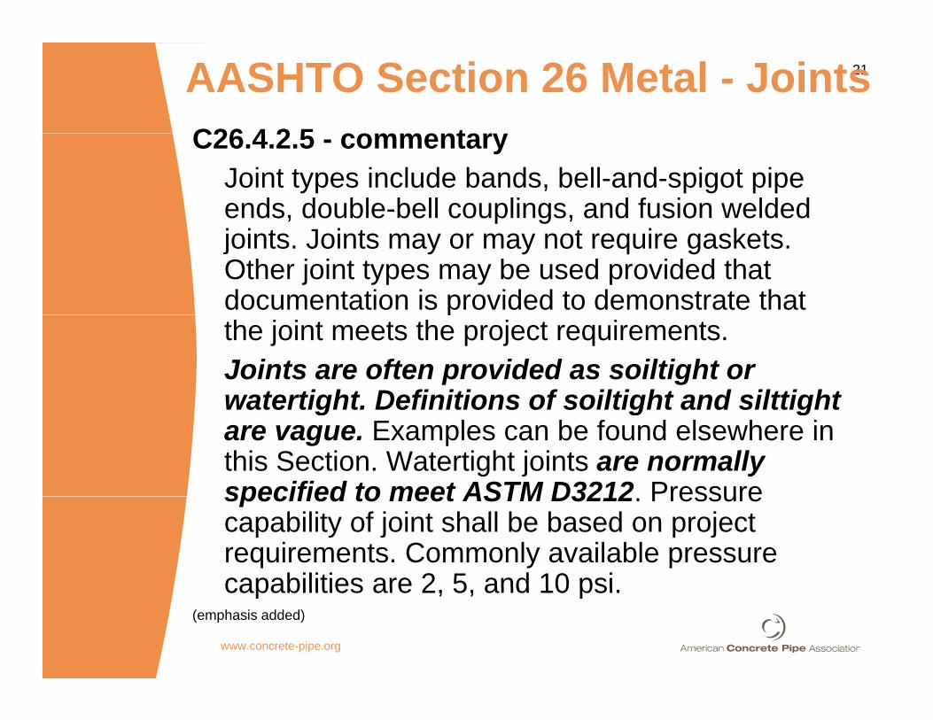
AASHTO Section 26 Metal - JointsC26.4.2.5 - commentary
Joint types include bands, bell-and-spigot pipe ends, double-bell couplings, and fusion welded joints. Joints may or may not require gaskets. Other joint types may be used provided that documentation is provided to demonstrate that pthe joint meets the project requirements.Joints are often provided as soiltight or watertight Definitions of soiltight and silttightwatertight. Definitions of soiltight and silttight are vague. Examples can be found elsewhere in this Section. Watertight joints are normally specified to meet ASTM D3212 Pressurespecified to meet ASTM D3212. Pressure capability of joint shall be based on project requirements. Commonly available pressure capabilities are 2 5 and 10 psicapabilities are 2, 5, and 10 psi.
(emphasis added)
www.concrete-pipe.org
22
SRPE Marketing Material“Achieves a water tight joint performance that sets it apart fromperformance that sets it apart from conventional pipe products.”Tested to 15 psi, the steel reinforcedTested to 15 psi, the steel reinforced High Performance (HP) joints greatly exceed ASTM’s 10.8 psi requirement. p qFor lower performance applications, 3 psi low head (LH) or soil tight (ST) j i t il bl L k fjoints are available. Leak-free ElectroFusion (EF) joints are also an optionoption.
www.concrete-pipe.org

23
SRPE Specification SheetSRPE Specification Sheet
Soil Tight Joints (30” – 96”) shall be plain ended SRPE pipe with Al i i d T 2 ( ti lAluminized Type 2 (or optional Polymeric coated) CMP coupling bands and elastomeric gasketsbands and elastomeric gaskets.
www.concrete-pipe.org
24
SRPE Specification SheetSRPE Specification SheetLow Head (LH) Joints (30” – 72”) h ll b k t d t t d hi hshall be gasketed, stress-rated high
density polyethylene bell and spigot joints that have been laboratoryjoints that have been laboratory tested to 3 psi when tested in accordance with ASTM D3212accordance with ASTM D3212.
www.concrete-pipe.org

25
SRPE Specification SheetSRPE Specification SheetHigh Performance (HP) Joints (30” 72”) h ll b k t d b ll(30” – 72”) shall be gasketed, bell and spigot joints where both the bell and spigot are reinforced with steeland spigot are reinforced with steel that is fully encased in stress-rated high density polyethylene and thathigh density polyethylene and that have been laboratory tested to 15 psi when tested in accordance with pASTM D3212.
www.concrete-pipe.org
26
SRPE Specification SheetElectroFusion (EF) Joints (36” –120”) shall utilize plain ended SRPE i ld d t th tili i l ipipe welded together utilizing exclusive
pressure testable ElectroFusion couplers The welded connectionscouplers. The welded connections provide a true in-field watertight system assured by the pressure testableassured by the pressure testable welded sleeves at each welded connection. The field installed ElectroFusion joints shall remain watertight with a “zero” leakage rate up t t t f 30 ito a test pressure of 30 psi.
www.concrete-pipe.org
27AASHTO Section 26 Metal
www.concrete-pipe.org
28AASHTO Section 26 Metal26.5.1 Continued
All pipe laying joining and
26.5.1 Continued
All pipe laying, joining, and backfilling shall be in accordance with the strictest of the followingwith the strictest of the following requirements: the Manufacturer’s instructions, the contract ,documents, or these Specifications.
www.concrete-pipe.org
29
SRPE Specification SheetInstallationInstallation shall be in accordance with ASTM D2321 “Practice for Underground Installation of Th l ti Pi f S dThermoplastic Pipe for Sewers and Other Gravity-Flow Applications” along with product specificalong with product-specific recommendations contained in manufacturers Installationmanufacturers Installation Guidelines.
www.concrete-pipe.org

30AASHTO Section 26 Metal
www.concrete-pipe.org
31
www.concrete-pipe.org
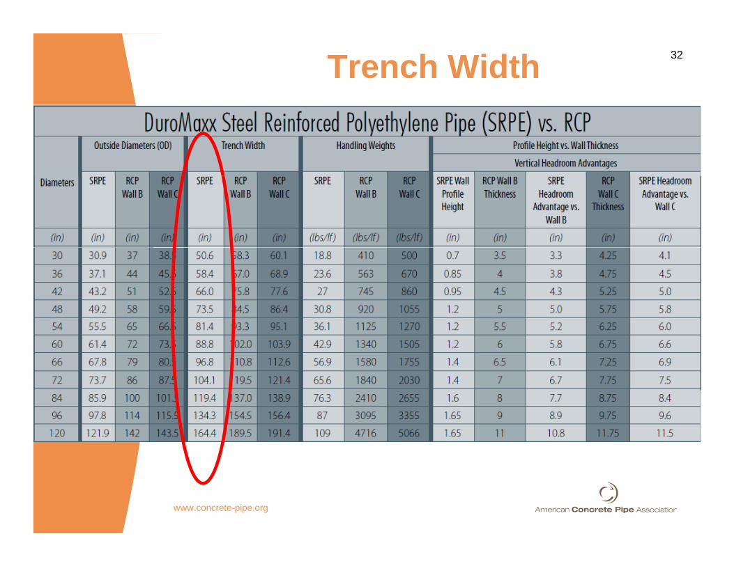
32Trench Width
www.concrete-pipe.org

33Trench WidthPi O t id ASTM AASHTO AASHTOPipe
DiameterOutside
DiameterASTM 2321
AASHTOSec. 30
AASHTOSec. 26
30 30.9 50.6 58.4 NA*36 37 1 58 4 67 7 NA*36 37.1 58.4 67.7 NA*42 43.2 66.0 76.8 NA*48 49.5 73.9 86.3 NA*54 55.5 81.4 95.3 NA*60 61.4 88.8 104.1 NA*66 67 8 96 8 113 7 NA*66 67.8 96.8 113.7 NA72 73.7 104.1 122.6 NA*84 85.9 119.4 140.9 NA*96 97.8 134.3 158.7 NA*
*For trench conditions, the trench shall be excavated to the width, depth, and grade shown in the contract documents
www.concrete-pipe.org
and grade shown in the contract documents.
34AASHTO Section 26 Inspection Requirements
26.5.7.1 – Visual Inspection
Inspection Requirements
pFinal internal inspections shall be conducted on all buried installations to evaluate issues that may affect long-term performance Final inspectionsaffect long term performance. Final inspections shall be conducted no sooner than 30 days after completion of installation and final fill.
(emphasis added)(emphasis added)
www.concrete-pipe.org

35AASHTO Section 26 Inspection Requirements
26.5.7.1 - Visual Inspection
Inspection Requirements
pSteel reinforced thermoplastic pipe shall be inspected prior to backfilling to ensure that the external reinforcing ribs do not lean anexternal reinforcing ribs do not lean an average of more than 15 degrees off of vertical within any 24.0 in. long continuous section of the pipe If this condition exists thatsection of the pipe. If this condition exists, that portion of the pipe shall be remediated or replaced. Joint types include bands, bell-and-spigot pipe ends double-bell couplings andspigot pipe ends, double bell couplings, and fusion welded joints.
(emphasis added)
www.concrete-pipe.org

36AASHTO Section 26 Inspection Requirements
26.5.7.2.2 – Installation Deflection for Steel-
Inspection Requirements
Reinforced Thermoplastic CulvertsThe pipe shall be evaluated to determine whether the internal diameter of the barrel has beenthe internal diameter of the barrel has been reduced more than five percent when measured not less than 30 days following completion of installationinstallation.
www.concrete-pipe.org

37AASHTO Section 26 Inspection Requirements
26.5.7.2.2 – Installation Deflection for Steel-
Inspection Requirements
Reinforced Thermoplastic CulvertsPipes shall be checked for deflection using a mandrel or any other device approved by themandrel or any other device approved by the Engineer that can physically verify the dimensions of the pipe and that is not limited by poor lighting waterflow pipe length or otherpoor lighting, waterflow, pipe length, or other limiting conditions of the installed environment. Pipes larger than 24.0 in. may be entered and deflection levels measured directlydeflection levels measured directly.
www.concrete-pipe.org

38AASHTO Section 26 Inspection Requirements
26.5.7.2.2 – Installation Deflection for Steel-
Inspection Requirements
Reinforced Thermoplastic CulvertsIn all pipe installations, at least ten percent of the total pipe footage on the project shall bethe total pipe footage on the project shall be randomly selected by the Engineer and inspected for deflection. Also, as determined by the 100 percent visual inspection in Articlethe 100 percent visual inspection in Article 26.5.7.1, all areas in which deflection can be visually detected shall be inspected for deflectiondeflection.
www.concrete-pipe.org

39AASHTO Section 26 Inspection Requirements
26.5.7.2.2 – Installation Deflection for Steel-Reinforced Thermoplastic Culverts
Inspection Requirements
Where direct measurements are made, a measurement shall be taken once every 10.0 ft for the length of the pipe and a minimum of four measurements per pipe installation are requiredinstallation are required.If a mandrel is used for the deflection test, it shall be a nine- (or greater odd number) arm mandrel and shall be sized and inspected by the Engineer prior to testing. Asized and inspected by the Engineer prior to testing. A properly sized proving ring shall be used to check or test the mandrel for accuracy. The mandrel shall be pulled through the pipe by hand with a rope or cable. Where applicable p lle s ma be incorporated in the s stem toapplicable, pulleys may be incorporated in the system to change the direction of pull so that inspection personnel need not physically enter the pipe or manhole.
www.concrete-pipe.org
40AASHTO Section 26 Inspection Requirements
26.5.7.2.2 – Installation Deflection for Steel-Reinforced Thermoplastic Culverts
Inspection Requirements
For locations where pipe deflection exceeds five percent of the inside diameter, an evaluation shall be conducted by the Contractor utilizing a Professional Engineer and submitted to the Engineer for review and approval, taking into consideration the severity of the deflection, structural integrity, environmental conditions, and the design service life of the pipe. Pipe remediation or replacement shall be required for locations where the evaluation finds that the deflection could be problematic. For locations where pipe deflection exceeds 7.5 percent of the inside pdiameter, remediation or replacement of the pipe is required.www.concrete-pipe.org
41SRPE Marketing
Was designed with a “smooth inner wall for outstanding hydraulics ”wall for outstanding hydraulics.
“Hi h fl t hi d ith“Higher flow rates are achieved with a smooth polyethylene water way thereby providing the engineer thethereby providing the engineer the design the option to reduce the pipeline diameter: Saving youpipeline diameter: Saving you money.”
www.concrete-pipe.org
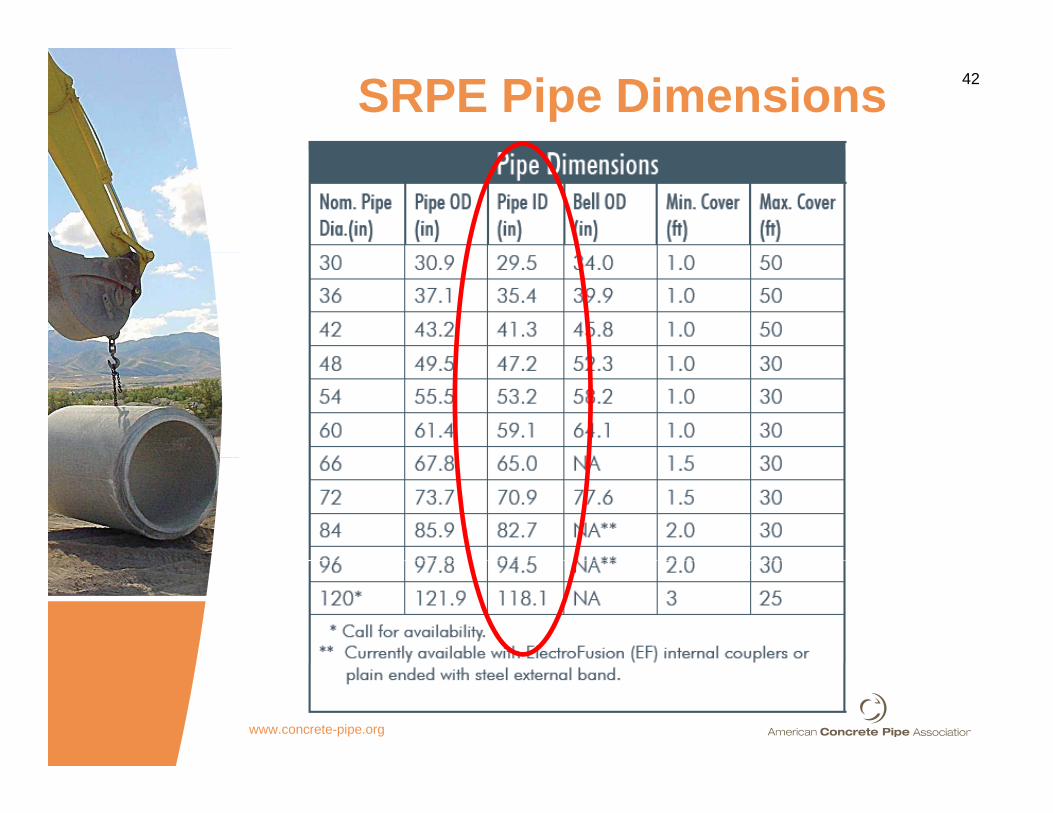
42SRPE Pipe Dimensions
www.concrete-pipe.org

43
SRPE Smooth Operator???SRPE Smooth Operator???
• SRPE does not provide an improved h d li ffi i h dhydraulic efficiency when compared to RCP. Laboratory tests have shown that just the opposite is true and RCPthat just the opposite is true and RCP has a slight edge in hydraulic efficientlyefficiently.
SRPE Manning’s n 0 012 0 014 SRPE Manning s n 0.012 - 0.014 SRPE Manning’s n 0.011 - 0.013
www.concrete-pipe.org

44

45
www.concrete-pipe.org
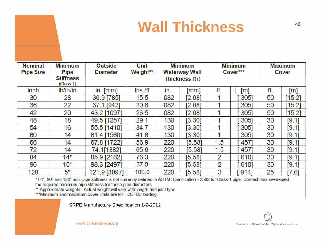
46Wall Thickness
S f S f
www.concrete-pipe.orgwww.concrete-pipe.org
SRPE Manufacture Specification 1-9-2012
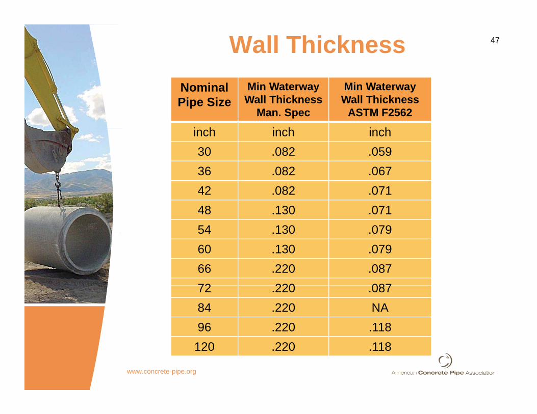
47Wall ThicknessNominal Pipe Size
Min Waterway Wall Thickness
Man. Spec
Min Waterway Wall Thickness
ASTM F2562
i h i h i hinch inch inch30 .082 .05936 .082 .06742 .082 .07148 .130 .07154 .130 .07954 .130 .07960 .130 .07966 .220 .08772 220 08772 .220 .08784 .220 NA96 .220 .118
120 .220 .118
www.concrete-pipe.org

48
Smooth Polyethylene Water Way?S oot o yet y e e ate ay
www.concrete-pipe.org

49
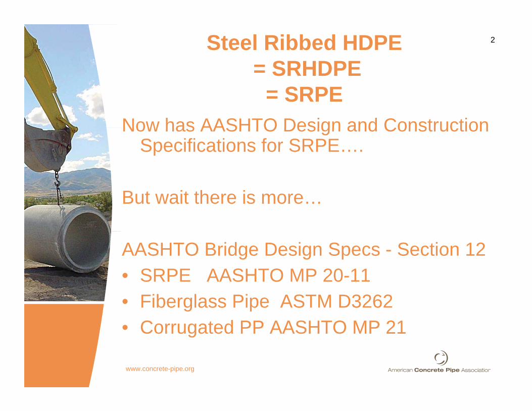
• Manufactured in standard lengths of
SRPE Marketing• Manufactured in standard lengths of
14 or 22-feet with bell and spigot jointsjoints.
• Fewer joints = faster installationLi ht i ht il h dl d d• Light weight = easily handled and installed
• Remember D2321 and f t ' i t ll ti idmanufacturer's installation guide
6-8” lifts.
www.concrete-pipe.org

50
Manufactured “with a pressure rated resin
SRPE StrengthManufactured with a pressure rated resin with predictable performance properties the engineer can depend on”
• Conventional HDPE evidence of slow crack growth (pipe cracking and delamination)C ti l HDPE h d• Conventional HDPE has creep and buckling issues
• SRPE has steel that will not creep and• SRPE has steel that will not creep and buckle
• SRPE uses pressure rated resins
www.concrete-pipe.org
p

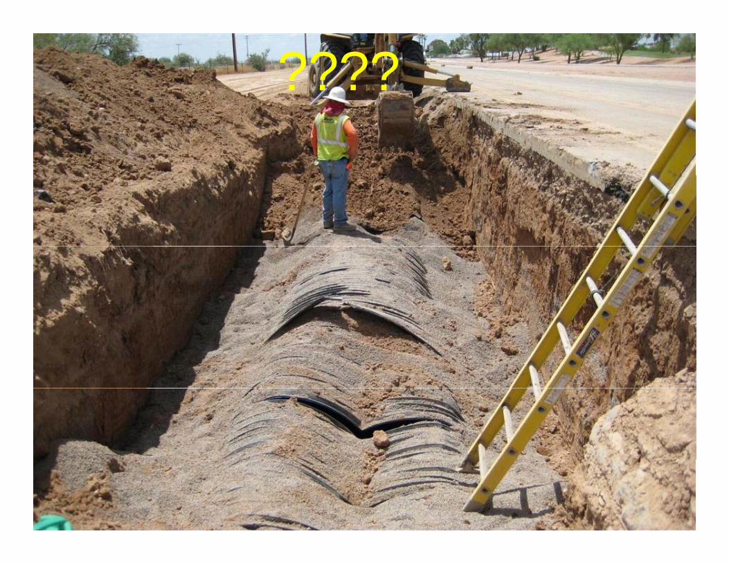
51SRHDPE WeaknessesIt’ t l ibb d b t it’ till HDPEIt’s steel ribbed, but it’s still HDPE
www.concrete-pipe.org

52
L D2321• Learn D2321• Learn D3212• Keep up with manufacturer’s own
installation guide and spec sheet• Work the specs from the local angle
www.concrete-pipe.org
53????
www.concrete-pipe.org