Embed Size (px)
Citation preview

SRI 8610C Gas Chromatograph Multiple Gas #3 GC configuration
The SRI 8610C Gas Chromatograph Multi-ple Gas #3 GC configuration is a versatile low cost way of analyzing many different kinds of gas samples. The GC pictured at right has two Multiple Gas #3 ( MG#3 ) configura-tions implemented in a sin-gle GC chassis so there are two gas sampling valves and four columns as well as four detectors. This is why the column oven looks so crowded. The MG#3 GC configuration is al-most identical to the MG#1 GC con-figuration except there is an addi-tional solenoid valve which when activated by the PeakSimple data system stops the flow of carrier gas in column 1. When the solenoid valve is actuated ( typically while the gas sampling valve is in the INJECT position ), column 1 has the same pressure applied to both its inlet and outlet. This stops the flow of carrier gas in column 1. The peaks which were in column 1 simply stop moving without broadening or distortion. The flow of carrier gas in column 2 actually increases while the solenoid is actuated since the full carrier gas head pressure is now applied across a shorter restriction ( one column in-stead of two in series ). The MG#3 GC configuration is slightly more flexible than the MG#1 because the stop flow capability allows a wider selection of columns to be used, where the MG#1 only works with silica gel as Column 1 and Mole-Sieve 13X as Column 2.
MultiGas#3 Instructions Page 1
SRI Tech Support 310-214-5092 www.srigc.com
solenoid
solenoid
Column1
Col 1 Col 2
Column 2
solenoid Column1
Column 2

SRI 8610C Gas Chromatograph Multiple Gas #3 GC configuration
The chromatograms shown on this page are a mix of natural gas and sulfur compounds. The top chromatogram shows the sulfur selective FPD response. The middle chromatogram shows the FID re-sponse. The two lower chromatograms show the FPD response ( black ) overlaid with the FID re-sponse ( red ). The PeakSimple event table shown at right ro-tates the valve from Load to Inject at .1 minutes and then back to Load at 1.00 minutes. Because even the first peak ( methane ) has not migrated from Column 1 though to Column 2 at this
time, the
equivalent effect is that the peaks are injected into and are sep-
arated by
MultiGas#3 Instructions Page 2
SRI Tech Support 310-214-5092 www.srigc.com
Col 1 Col 2
Col 1 Col 2
FPD Sulfur only
FID Hydrocarbons
FPD and FID overlaid
Just this section enlarged
FPD Sulfur only
Column 1 60 meter MXT1 .53mm 5 mic. Column 2 15 meter RTX Q-Plot .53mm

SRI 8610C Gas Chromatograph Multiple Gas #3 GC configuration
Instead, the MG#3 allows the Stop Flow solenoid to actuate at 3.5 minutes just after the Propane and COS migrate into Column 2 ( 15meter RTX
QPlot .53mm ). This traps the peaks after Propane in Column 1 while the peaks in Column 2 ( Methane, Ethane, Propane, H2S and COS ) separate and elute. Unlike col-umn 1 which does not separate COS and Propane, the peaks are well sepa-rated on Column 2 so quenching does not occur. Once Propane elutes from Column 2 ( about 10 minutes ) the valve rotates back to the Load position and the Stop
MultiGas#3 Instructions Page 3
SRI Tech Support 310-214-5092 www.srigc.com
Col 1
Col 1
Col 2
Col 2
solenoid
Solenoid turns off and valve rotates to Load at 10.00 minutes, just after propane
Solenoid turns on at 3.5 minutes, stopping flow in Col 1
Oven temperature 40C for 10 minutes then 20C/min to 200C
FPD Sulfur only

SRI 8610C Gas Chromatograph Multiple Gas #3 GC configuration
The MG#3 GC configuration is also use-ful with other column combinations. In this example, Column 1 is a 3’ HaysepD and Column 2 is a 6’ MS13X. The sam-ple is first run on the 3’ HaysepD using the event table shown at right. Because the valve is rotated back to the Load po-sition almost immediately after injection ( .1 minutes ) the separation occurs as if Column2 was not even connected. ( no hardware changes are required to pro-duce this effect ). There is a convenient gap between Methane and CO2 where it would make sense to activate the stop-flow solenoid valve to immobilize the CO2 and heavier peaks in Column1 while the H2, O2, N2, Methane and CO peaks elute from Column2.
MultiGas#3 Instructions Page 4
SRI Tech Support 310-214-5092 www.srigc.com
HayD col 1
Col 2 13X
Solenoid on at .9 minutes
This would be a good time ( .9 minutes ) to acti-vate the stop-flow solenoid. Just after the Methane migrates onto Column2 but before the CO2 and heavier peaks
Solenoid off
TCD detector
Oven temperature 40C for 10 minutes then 20C/min to 200C
HayD col 1
Col 2 13X

SRI 8610C Gas Chromatograph Multiple Gas #3 GC configuration
The same sample is injected again using the Event table shown at right. The valve stays in the Load position until 4.00 minutes. The Stop-Flow solenoid is actuated at .9 minutes ( determined from the chromatogram on the previous page ) and de-activated at 4.00 mintes. This results in H2, O2, N2, CH4 and CO migrating onto Column2 ( Mole-Sieve13X ) where they separate and elute into the TCD detector. Once CO elutes ( about 4.00 minutes ), the valve is rotated back to the Load position and the Stop-Flow solenoid is de-energized. The concept of immobilizing peaks by stopping the flow is applicable to many situations and many column combina-tions, not just the two examples present-ed here.
MultiGas#3 Instructions Page 5
SRI Tech Support 310-214-5092 www.srigc.com
Col 1
Col 1
Col 2
Col 2
Solenoid on at .9 minutes
Solenoid off
TCD detector
Stop-Flow solenoid on at .9 and off at 4.00 minutes. Valve back to Load position at 4.00 minutes

SRI 8610C Gas Chromatograph Multiple Gas #3 GC configuration
Another example is Natural Gas. Set the Event table up to inject and then im-mediately rotate the valve back to Load after .1 minutes in the Inject position. This has the effect of performing the analysis as if Column2 was not in the system. We call this the “ Timing Mode” Column 1 is a 3’ Haysep D and Column 2 is a 6’ MS13X. The Haysep D does not separate Oxygen and Nitrogen or CO. Set the Stop-Flow solenoid time by finding the gap between Methane and CO2, in this case about .9 minutes.
MultiGas#3 Instructions Page 6
SRI Tech Support 310-214-5092 www.srigc.com
Col 1
Col 1
Col 2
Col 2
Solenoid on at .9 minutes
Solenoid off
The gap between Me-thane and CO2 is a good time to actuate
the Stop-Flow solenoid
TCD detector
Zoom in

SRI 8610C Gas Chromatograph Multiple Gas #3 GC configuration
With the Event table modified, the Oxy-gen, Nitrogen and Methane separate on the MS13X. Then the Stop-Flow sole-noid is de-energized and valve rotated back to Load position ( both at 4.00 minutes ) and the remaining peaks ( Ethane, Propane, Water, Butanes, and Pentanes ) which were immobilized on
the
MultiGas#3 Instructions Page 7
SRI Tech Support 310-214-5092 www.srigc.com
Col 1 HayD
Col 1 HayD
Col 2 MS13X
Col 2 MS13X
Solenoid on at .9 minutes
Solenoid Off at 4.00
The Stop-Flow solenoid is actuated at .9 minutes and de-energized at 4.00 minutes. The valve is rotated
back to Load also at 4.00 minutes
TCD detector
Zoom in

SRI 8610C Gas Chromatograph Multiple Gas #3 GC configuration
Another example uses a 9’ Haysep D column and a 6’ Mole Sieve 13X. With the event table set to the “ Timing Mode” we can see there is a nice gap at 1.5 minutes where we can actuate the Stop-Flow solenoid. The Stop-Flow chroma-togram separates the O2, N2 and CO on the 13X column, then the Methane and CO2 on the Haysep column .
MultiGas#3 Instructions Page 8
SRI Tech Support 310-214-5092 www.srigc.com
Col 1
Col 1
Col 2
Col 2
Solenoid on at 1.5 minutes
Solenoid Off at 4.00
The Stop-Flow solenoid is actuated at 1.5 minutes and de-energized at 4.00 minutes. The valve is rotated
back to Load also at 4.00 minutes
TCD detector
The gap in the chromatogram between the combined O2, N2 and CO peak and the Methane peak is a good
place to actuate the Stop-Flow solenoid

SRI 8610C Gas Chromatograph Multiple Gas #3 GC configuration
Application Example-2 step process The SRI 8610C GC is configured as a Multiple Gas #3 with TCD detector. There are two columns in the column oven, a 2 meter Haysep-D and a 2 me-ter MoleSieve 13X. There is a 10port gas sampling valve ( Relay G ) located in the valve oven as well as the Stop-Flow solenoid ( Relay A ).
MultiGas#3 Instructions Page 9
SRI Tech Support 310-214-5092 www.srigc.com
Stop-Flow Solenoid

SRI 8610C Gas Chromatograph Multiple Gas #3 GC configuration
Application Example-2 step process The oven temperature program is set to hold the column oven at 40C for 10 minutes, then ramp at 20 degrees per minute to 200C. The Event table: 1) Auto-zeros the detector signal at
0.00 minutes. 2) Makes a sound at zero minutes to
confirm to the operator that the anal-ysis has begun.
3) Actuates Relay A ( the Stop-Flow So-lenoid ) for .2 minutes ( 12 sec-onds ).The purpose of this is to purge the Stop-Flow Solenoid of any air pri-or to the analysis.
4) The gas sampling valve ( Relay G ) is actuated at .5 minutes and de-actuated at .8 minutes. This results in the sample being injected onto the Haysep-D column, which is upstream at the moment of injection. When the valve is rotated back to the Load po-sition at .8 minutes the Haysep-D column becomes the downstream column and the sample will not have had enough time to make its way through so the peaks will elute di-rectly into the TCD detector without going through the MoleSieve 13X column at all. The chromatogram which results will be identical to a system with just a Haysep-D column.
MultiGas#3 Instructions Page 10
SRI Tech Support 310-214-5092 www.srigc.com

SRI 8610C Gas Chromatograph Multiple Gas #3 GC configuration
Application Example-2 step process The results of the Step1 chromato-gram is shown at right. Since the peaks only traveled through the Haysep-D column there is no separation of Hydro-gen, Oxygen, Nitro-gen or CO. Those peaks all elute to-gether in one big peak. It is clear from the chromato-gram that an appro-priate time to actu-ate the Stop-Flow solenoid would be at about 2.3 minutes. This is just after the methane peak and before the CO2 peak. The event table is modified so that Relay A which controls the Stop-Flow Solenoid is turned on at 2.3 minutes. Notice that the entry for Relay G off is removed ( compared to the first Event table ) since we do not know at this time when to do this. This is what will be de-termined when we re-inject the same sample in Step 2.
MultiGas#3 Instructions Page 11
SRI Tech Support 310-214-5092 www.srigc.com
H2,O2,N2 and CO All co-elute
CO2 Ethylene+Acetylene Ethane
CH4
SRI 8610C Gas Chromatograph Multiple Gas #3 GC configuration
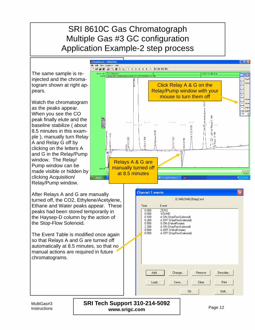
Application Example-2 step process The same sample is re-injected and the chroma-togram shown at right ap-pears. Watch the chromatogram as the peaks appear. When you see the CO peak finally elute and the baseline stabilize ( about 8.5 minutes in this exam-ple ), manually turn Relay A and Relay G off by clicking on the letters A and G in the Relay/Pump window. The Relay/Pump window can be made visible or hidden by clicking Acquisition/Relay/Pump window. After Relays A and G are manually turned off, the CO2, Ethylene/Acetylene, Ethane and Water peaks appear. These peaks had been stored temporarily in the Haysep-D column by the action of the Stop-Flow Solenoid. The Event Table is modified once again so that Relays A and G are turned off automatically at 8.5 minutes, so that no manual actions are required in future chromatograms.
MultiGas#3 Instructions Page 12
SRI Tech Support 310-214-5092 www.srigc.com
Relays A & G are manually turned off
at 8.5 minutes
Click Relay A & G on the Relay/Pump window with your
mouse to turn them off

SRI 8610C Gas Chromatograph Multiple Gas #3 GC configuration
Application Example-2 step process Some user’s do not have enough sam-ple to load the loop of the gas sampling valve ( 10ml ). In this case, a smaller volume of sample can be injected via the on-column injector. Refer to the valve diagram and you can see that in order to inject via the on-column injector, the valve must FIRST be positioned in the INJECT position. This puts the Haysep D as the first col-umn the sample will encounter. When the valve is rotated to the INJECT posi-tion, the contents of the loop are una-voidably injected. For this reason, you must purge the sample loop with carrier gas. A simple way to do this is to fabricate a “tee” fitting at the point the carrier gas enters the GC. The third leg of the “tee” is connected to a restrictor tube which limits the purge flow to about 10ml/minute. We use 4meters of 1/16” stain-less tubing with a .1mm id. At 30psi inlet pressure this limits the helium carrier purge flow through the loop to about 10ml/minute.
MultiGas#3 Instructions Page 13
SRI Tech Support 310-214-5092 www.srigc.com

SRI 8610C Gas Chromatograph Multiple Gas #3 GC configuration
Application Example-2 step process The other end of the restrictor tube is connected to the sample IN port on the front of the valve oven. The purge gas keeps the loop filled with carrier gas ( rather than air etc ). The purge gas exhausts from the sample OUT port. The on-column injector is plumbed with stainless tubing going from the injector to port#4 of the gas sampling valve. So when you make a syringe injection the sample takes the same path as it would have if you injected the usual way via the sample loop. All the timing ( Relay A and Relay G ) is the same whether you inject via the on-column injector or via the loop. GCs manufactured after January 2014 have a special low dead volume injec-tion liner which gives slightly sharper peaks when doing the on-column injec-tion in this manner. The liner ( SRI part# 8670-1503 ) looks like the photo at right.
MultiGas#3 Instructions Page 14
SRI Tech Support 310-214-5092 www.srigc.com

SRI 8610C Gas Chromatograph MG3epc configuration
January 2015 The Multiple Gas #3 GC configuration has been slightly modified ( for better performance ) on all units manufactured after January 2015 to incorporate an Electronic Pressure Controller ( EPC ) instead of the Stop-Flow solenoid. These instructions assume you have a 6” Haysep D and 6’MS13X column in-stalled. If you have different columns you may have to modify the temperature, pressure and events from what is shown. Set up the Channel 1 temperature pro-gram as shown here. Set up the Channel 1 Event table as shown here. Call the Event table MG3epcStart.evt.
MultiGas#3 Instructions Page 15
SRI Tech Support 310-214-5092 www.srigc.com
The MG3EPC configuration has a 2nd carrier gas control

SRI 8610C Gas Chromatograph MG3epc configuration
January 2015 Set up the Channel 2 Pressure Program as shown. Save this as MG3EPCstart.flo. You may have to ensure that channel 2 is Active if it is not already. Inject a calibration gas standard such as the one shown below.
MultiGas#3 Instructions Page 16
SRI Tech Support 310-214-5092 www.srigc.com

SRI 8610C Gas Chromatograph MG3epc configuration
January 2015 The chromatogram which results from the initial timing experiment shows that 2.3 minutes would be a good time to stop the flow in the upstream col-umn ( the stop-flow time ). Modify the Channel1 Event table as shown here. Save the Event table as MG3epcFi-nal.evt. Note that the time for Relay G Off ( 7 minutes ) is a guess, and may be adjust-ed later. Modify the pressure program in Channel 2 as shown here. Some of the pressures and times are also a guess, and will probably need to be fine tuned. The pressure is allowed to drop from 40 back to 0 just a little before the 7 minute Relay G valve rotation so the pressure is not so high when the valve rotates. This makes the artifact peak a little smaller.
MultiGas#3 Instructions Page 17
SRI Tech Support 310-214-5092
2.3 minutes was chosen as the time to stop the flow

SRI 8610C Gas Chromatograph MG3epc configuration
January 2015 This is the final chromatogram using the temperature program, event table and pressure programs shown in the preceding pages.
There are a couple of “artifact” peaks which occur as a consequence of the valve switch and pressure changes.
MultiGas#3 Instructions Page 18
SRI Tech Support 310-214-5092 www.srigc.com

SRI 8610C Gas Chromatograph MG3epc configuration
January 2015 Fortunately, the artifact peaks do not in-terfere with most of the other peaks nor-ally measured. See the chromatogram below with C2-C4 hydrocarbons added to the test mix.
MultiGas#3 Instructions Page 19
SRI Tech Support 310-214-5092 www.srigc.com
FID/methanizer
TCD

This is the flow path at Time 0. The StopFlow EPC is set to 3 psi to save carrier gas since any flow from the EPC just merges with the carrier gas exiting the Haysep col-
umn prior to the detector.
SRI 8610C Gas Chromatograph MG3epc configuration
January 2015
MultiGas#3 Instructions Page 20
SRI Tech Support 310-214-5092 www.srigc.com
10 port Valve Load
position
MS13X column Haysep column Detector
Stop-flow
EPC Restrictor 12” x .005”
10 port Valve Inject
position
MS13X column Haysep column Detector
Stop-flow
EPC 20psi
Restrictor 12” x .005”
This is the flow path at Time 0.02 minutes. The StopFlow EPC is set to about 20psi to insure that as the peaks pass through the junction between the two columns no mole-
cules diffuse backwards into the stop-flow tubing towards the EPC.
10 port Valve Load
position
MS13X column Haysep column Detector
Stop-flow
EPC 40psi
Restrictor 12” x .005”
This is the flow path at Time 2.32 minutes. The StopFlow EPC is set to about 40psi to prevent the peaks which remain in the Haysep column from moving at all.
The peaks ( H2, O2, N2, CH4 and CO ) which have already passed into the MS13X column continue to move towards the detector
25 psi
3 psi
25psi
20psi
Flow this way
25psi
40psi
No flow this way
Very low flow
Just a little flow

This is the flow path at Time 7.00 The valve is rotated back to the Load position and
the StopFlow EPC is set to 0 psi to save carrier gas since any flow from the EPC just merges with the carrier gas exiting the Haysep column prior to the detector.
SRI 8610C Gas Chromatograph MG3epc configuration
January 2015
MultiGas#3 Instructions Page 21
SRI Tech Support 310-214-5092 www.srigc.com
10 port Valve Load
position
MS13X column Haysep column Detector
Stop-flow
EPC 0 psi
Restrictor 12” x .005”
25 psi