Embed Size (px)
Citation preview
SR POOL AND SPA HEATERNATURAL GAS / LP GASO W N E R ’ S M A N U A L
INSTALLATION, OPERATION & PARTS
MODELS200K BTU/HR SR200NA SR200LP333K BTU/HR SR333NA SR333LP400K BTU/HR SR400NA SR400LP
Sta-Rite Pool/Spa Group
293 Wright Street, Delavan, WI 53115International: 262-728-5551, FAX: 262-728-7550www.starite.comUnion City, TN • Delavan, WI • Mississauga, Ont. • Murrieta, CA
© 2004, Sta-Rite Industries Printed in U.S.A. S396 (Rev. 2/13/04)
If the information in these instructions is not followed exactly, a fire or explosion may result causing property damage, personal injury or death.
– Do not store or use gasoline or other flammable vapors and liquids in the vicinity of this or any other appliance.
– WHAT TO DO IF YOU SMELL GAS• Do not try to light any appliance.• Do not touch any electrical switch; do not use any phone in your building.• Immediately call your gas supplier from a neighbor’s phone. Follow the
gas supplier’s instructions.• If you cannot reach your gas supplier, call the fire department.
– Installation and service must be performed by a qualified installer, serviceagency or the gas supplier.
SPECIAL INSTRUCTIONS TO OWNERRetain this manual for future reference.This manual supplies information for the installation, operation,and servicing of the appliance. It is strongly recommended thatthis manual be reviewed completely before proceeding with aninstallation. Its use will reduce service calls and chance of injuryand will lengthen product life.
2668 039
FILTER
PUMP
AUX
1
AUX
2
HIGH SPEED
LOW SPEED
BOOSTER PUMP
INSTALLATION, OPERATION AND SERVICE MANUAL
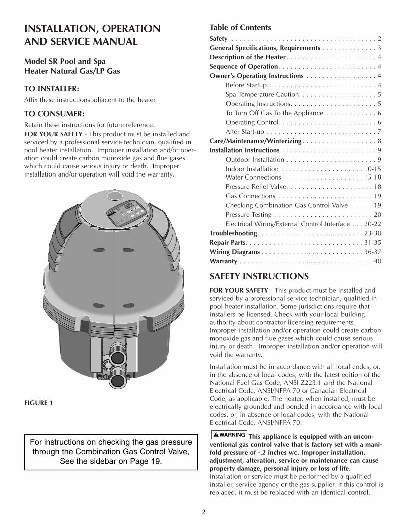
Model SR Pool and Spa Heater Natural Gas/LP Gas
TO INSTALLER:Affix these instructions adjacent to the heater.
TO CONSUMER:Retain these instructions for future reference.FOR YOUR SAFETY - This product must be installed andserviced by a professional service technician, qualified inpool heater installation. Improper installation and/or oper-ation could create carbon monoxide gas and flue gaseswhich could cause serious injury or death. Improperinstallation and/or operation will void the warranty.
FIGURE 1
Table of ContentsSafety . . . . . . . . . . . . . . . . . . . . . . . . . . . . . . . . . . . . . 2General Specifications, Requirements . . . . . . . . . . . . . . 3Description of the Heater . . . . . . . . . . . . . . . . . . . . . . . 4Sequence of Operation . . . . . . . . . . . . . . . . . . . . . . . . . 4Owner’s Operating Instructions . . . . . . . . . . . . . . . . . . 4
Before Startup. . . . . . . . . . . . . . . . . . . . . . . . . . . . 4Spa Temperature Caution . . . . . . . . . . . . . . . . . . . 5Operating Instructions. . . . . . . . . . . . . . . . . . . . . . 5To Turn Off Gas To the Appliance . . . . . . . . . . . . . 6Operating Control. . . . . . . . . . . . . . . . . . . . . . . . . 6After Start-up . . . . . . . . . . . . . . . . . . . . . . . . . . . . 7
Care/Maintenance/Winterizing . . . . . . . . . . . . . . . . . . . 8Installation Instructions . . . . . . . . . . . . . . . . . . . . . . . . 9
Outdoor Installation . . . . . . . . . . . . . . . . . . . . . . . 9Indoor Installation . . . . . . . . . . . . . . . . . . . . . 10-15Water Connections . . . . . . . . . . . . . . . . . . . . 15-18Pressure Relief Valve. . . . . . . . . . . . . . . . . . . . . . 18Gas Connections . . . . . . . . . . . . . . . . . . . . . . . . 19Checking Combination Gas Control Valve . . . . . . 19Pressure Testing . . . . . . . . . . . . . . . . . . . . . . . . . 20Electrical Wiring/External Control Interface . . . 20-22
Troubleshooting. . . . . . . . . . . . . . . . . . . . . . . . . . . 23-30Repair Parts. . . . . . . . . . . . . . . . . . . . . . . . . . . . . . 31-35Wiring Diagrams . . . . . . . . . . . . . . . . . . . . . . . . . . 36-37Warranty . . . . . . . . . . . . . . . . . . . . . . . . . . . . . . . . . . 40
SAFETY INSTRUCTIONSFOR YOUR SAFETY - This product must be installed andserviced by a professional service technician, qualified inpool heater installation. Some jurisdictions require thatinstallers be licensed. Check with your local buildingauthority about contractor licensing requirements.Improper installation and/or operation could create carbonmonoxide gas and flue gases which could cause seriousinjury or death. Improper installation and/or operation willvoid the warranty.
Installation must be in accordance with all local codes, or,in the absence of local codes, with the latest edition of theNational Fuel Gas Code, ANSI Z223.1 and the NationalElectrical Code, ANSI/NFPA 70 or Canadian ElectricalCode, as applicable. The heater, when installed, must beelectrically grounded and bonded in accordance with localcodes, or, in absence of local codes, with the NationalElectrical Code, ANSI/NFPA 70.
This appliance is equipped with an uncon-ventional gas control valve that is factory set with a mani-fold pressure of -.2 inches wc. Improper installation,adjustment, alteration, service or maintenance can causeproperty damage, personal injury or loss of life.Installation or service must be performed by a qualifiedinstaller, service agency or the gas supplier. If this control isreplaced, it must be replaced with an identical control.
2
2668 10
FILTER
PUMP
AUX1
AUX2
HIGH SPEED
LOW SPEED
BOOSTER PUMP
For instructions on checking the gas pressurethrough the Combination Gas Control Valve,
See the sidebar on Page 19.
SAFETY INSTRUCTIONS (Continued)Do not attempt to adjust the gas flow by adjusting the reg-ulator setting.
Risk of fire or explosion from incorrect fueluse or faulty fuel conversion. Do not try to run a heater setup for natural gas on LP gas (Propane) or vice versa. Onlyqualified service technicians should attempt to convertheater from one fuel to the other. Do not attempt to alter the rated input or type of gas bychanging the orifice. If it is necessary to convert to a differ-ent type of gas, consult your Sta-Rite dealer. Serious mal-function of the burner can occur which may result in lossof life. Any additions, changes, or conversions required inorder for the appliance to satisfactorily meet the applica-tion needs must be made by a Sta-Rite dealer or otherqualified agency using factory specified and approvedparts. The heater is available for use with natural gas or LP(propane) gas. Refer to the nameplate for the type of gasthe heater is equipped to use. • Use heater only with the fuel for which it is designed.
Do not attempt to convert from one type of gas toanother.
• If heater design does not match available fuel, have aqualified service technician convert the heater to thecorrect fuel before putting heater into operation.
Risk of fire or explosion from flammablevapors. Do not store gasoline, cleaning fluids, varnishes,paints, or other volatile flammable liquids near heater or inthe same room with heater.
Risk of fire, carbon monoxide poisoning, orasphyxiation if exhaust venting system leaks. Only quali-fied service technicians should attempt to service theheater, as leakage of exhaust products or flammable gasmay result from incorrect servicing.
Risk of explosion if an LP (propane) gas unitis installed in a pit or other low spot. LP gas is heavierthan air. Do not install an LP gas fired heater in pits orother locations where gas might collect. Consult localcodes and fire protection authorities about specific installa-tion requirements and restrictions. Locate the heater awayfrom LP gas storage and filling equipment as specified bythe Standard for the Storage and Handling of LiquifiedPetroleum Gases, ANSI/NFPA 58 (latest edition).
Risk of asphyxiation if exhaust is not correct-ly vented. Follow venting instructions exactly wheninstalling heater. Do not use a draft hood with this heater,as the exhaust is under pressure from the burner blowerand a draft hood will allow exhaust fumes to blow into theroom housing the heater. The heater is supplied with an integral venting system foroutdoor installation. A vent conversion kit (See Page 14 forPart Numbers for Conversion Kits) is available for indoorinstallations. Use the specified venting, and only the speci-fied venting, when heater is installed indoors.
Label all wires prior to disconnection whenservicing controls. Wiring errors can cause improper anddangerous operation.Connect heater to 120 Volt, 60 Hz., 1 Phase power only.Verify proper operation after servicing.Do not allow children to play on or around heater or asso-ciated equipment.Never allow children to use the pool or spa without adultsupervision.Read and follow other safety information contained in thismanual prior to operating this pool heater.
GENERAL SPECIFICATIONS/REQUIREMENTSNOTICE: Combustion air contaminated by corrosive chemi-cal fumes can damage the heater and will void the warranty.NOTICE: The Combination Gas Control Valve on thisappliance differs from most appliance gas controls. If itmust be replaced, for safety reasons replace it only with anidentical gas control.NOTICE: The jacket covers must be in place to provideproper ventilation. Do not operate the heater for more thanfive (5) minutes with the jacket covers removed.This heater is design certified by CSA International as com-plying with the Standard for Gas-Fired Pool heaters, ANSIZ21.56*CSA 4.7, and is intended for use in heating fresh-water swimming pools or spas. NOTICE: Do not use this heater as a heating boiler, waterheater, or for heating salt-water pools. This heater isintended for use in heating fresh water swimming pools orspas only.The heater requires an external 120 VAC single-phase elec-tric power source.For indoor installation, the heater must be located as closeas practical to a chimney or gas vent. The heater is design certified by CSA International forinstallation on combustible flooring. Specified minimumclearances must be maintained to combustible surfaces(see “Installation Instructions”, Pages 9 - 11).The heater should be located in an area where leakage ofthe heater or connections will not result in damage to thearea adjacent to the heater or to the structure. When suchlocations cannot be avoided, it is recommended that a suit-able drain pan, adequately drained, be installed under theheater. The pan must not restrict air flow. The heater may not be installed within five feet of theinside surface of a pool or spa unless it is separated by asolid fence, wall or other permanent barrier. LPG (Propane) fired heaters must not be installed ingarages in Massachusetts, by order of the MassachusettsState Fire Marshall. For more information, call the FireMarshall’s office.
3
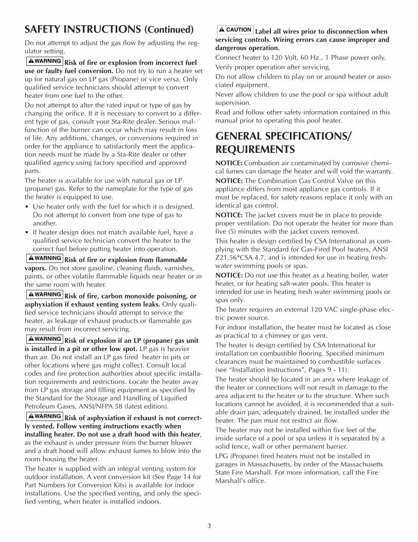
DESCRIPTION OF THE HEATER
FIGURE 2
Figure 2 is a diagram of the heater showing how it operates.Precisely matched orifice plates meter the air and gas intothe mixer. The blower draws the air and gas through themixer and forces it into the burner’s flameholder. A sealedheat exchanger surrounds the flameholder, dischargingexhaust gases out the flue.Two inch PVC water piping connects directly to the mani-fold/header on the heat exchanger using 2” PVC slip unionsprovided with the heater. The outer manifold remains cool;no heat sinks are required. A thermal regulator and an inter-nal bypass regulate the water flow through the heatexchanger to maintain the correct outlet temperature.A plastic jacket with the top half split for access surrounds
the assembly. The heater control board assembly, set intothe top of the jacket, contains the operating controls.
SEQUENCE OF OPERATIONAn electronic temperature sensing thermistor in the mani-fold adapter inlet controls the heater operation. When theinlet water temperature drops below the temperature set onthe operating control, the burner controller suppliespower to the combustion air blower through a series ofsafety interlocks. The interlocks consist of • the pressure switch (PS), which senses that the pump is
running, • the high limit switch (HLS), which opens if the heat
exchanger outlet temperature goes above 135°F, and• the automatic gas shutoff (AGS) switch, which opens if
the heat exchanger outlet temperature goes above140°F.
• the stack flue sensor (SFS), which shuts down the heaterif the flue gas temperature reaches 500°F.
The air flow switch (AFS) senses the pressure drop acrossthe air metering orifice. As soon as there is sufficient airflow, the AFS closes, closing the circuit to the hot surfaceignition (HSI), which ignites the fuel mixture. On a call for heat, the blower and HSI are energized. Inabout 20 seconds, the gas valve opens and ignition occurs.The HSI then switches to a sensing mode and monitors theflame. The heater is equipped with a digital operating control thatenables the user to pre-set the desired pool and spa watertemperatures. The control enables the user to selectbetween pool and spa heating, and features a digital dis-play that indicates the water temperature.
OWNER’S OPERATING INSTRUCTIONSFOR YOUR SAFETY READ BEFORE OPERATING
IF YOU DO NOT FOLLOW THESEINSTRUCTIONS EXACTLY, A FIRE OR EXPLOSIONMAY RESULT, CAUSING PROPERTY DAMAGE, PERSONAL INJURY OR LOSS OF LIFE.
START-UP AND OPERATIONSTART-UP AND SHUTDOWN INSTRUCTIONS ARE ONTHE LABEL ATTACHED TO THE COVER OF THE APPLI-ANCE CONTROL BOX.
BEFORE START-UPA. This appliance does not have a pilot. It is equipped
with an ignition device which automatically lights theburner. Do not try to light the burner by hand.
B. BEFORE OPERATING check for odor. Sniff all aroundthe appliance area for gas. Be sure to sniff next to thefloor, because some gas (such as propane) is heavierthan air and will settle on the floor.
4
Gas
Air
Mixer
Blower
Inlet(Cold Water)
Exh
aust
Heating CoilsOutlet(MixedWater)
Burner
WHAT TO DO IF YOU SMELL GAS• Do not try to light any appliance.• Do not touch any electrical switch; do not use any
phone in your building.• Immediately call your gas supplier from a neighbor’s
phone. Follow the gas supplier’s instructions.• If you cannot reach your gas supplier, call the fire
department.C. Use only your hand to push in or turn the gas control
knob. Never use tools. If the knob will not push in orturn by hand, don’t try to repair it, call a qualified ser-vice technician. Force or attempted repair may resultin fire or explosion.
D. Do not use this heater if any part has been underwater. Immediately call a qualified service technicianto inspect the heater and to replace any part of thecontrol system and any gas control which has beenunder water.
E. Do not operate the pool heater unless the pool or spais properly filled with water.
F. Before operating the appliance for the first time or afterit has been off for an extended time, perform the fol-lowing checklist:1. Remove debris or other articles from inside the
heater and the area around the heater and itsexhaust vent. Make sure the ventilation openings areclear of debris or obstruction. For installations in anenclosed space, make sure openings for combustionand ventilation air are unobstructed.
2. Keep heater area clear and free from combustibles,flammable liquids and chemicals.
3. Check that all water connections are tight.4. Water must be flowing through the heater during
operation. Make sure that the pool/spa is filled withwater and have the pump operating. Check thatwater flow is unobstructed from the appliance.When operating for the first time or after an extend-ed shut-down, run filter pump for several minutesto clear all air from the system.
SPA TEMPERATURE CAUTION All safety rules recommended by the U.S. ConsumerProduct Safety Commission should be observed whenusing a spa or hot tub, including:1. Spa or hot tub water temperatures should never exceed
104°F (40°C). A temperature of 100°F (38°C) is consid-ered safe for a healthy adult. Special caution is sug-gested for young children.
2. Drinking of alcoholic beverages before or during spaor hot tub use can cause drowsiness which could leadto unconsciousness and subsequently result in drowning.
3. Pregnant women beware! Soaking in water above 102°F (39°C) can cause fetal damage during the firstthree months of pregnancy (resulting in the birth of abrain-damaged or deformed child). Pregnant womenshould follow the 100°F (38°C) maximum rule.
4. Before entering the spa or hot tub, users should checkthe water temperature with an accurate thermometer;spa or hot tub thermostats may err in regulating watertemperature.
5. Persons with medical history of heart disease, circula-tory problems, diabetes or blood pressure problemsshould obtain their physician’s advice before usingspas or hot tubs.
6. Persons taking medications which induce drowsiness,such as tranquilizers, antihistamines or anticoagulants,should not use spas or hot tubs.
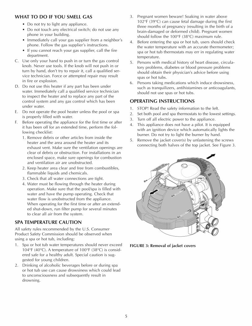
OPERATING INSTRUCTIONS1. STOP! Read the safety information to the left.2. Set both pool and spa thermostats to the lowest settings.3. Turn off all electric power to the appliance.4. This appliance does not have a pilot. It is equipped
with an ignition device which automatically lights theburner. Do not try to light the burner by hand.
5. Remove the jacket cover(s) by unfastening the screwsconnecting both halves of the top jacket. See Figure 3.
FIGURE 3: Removal of jacket covers
5
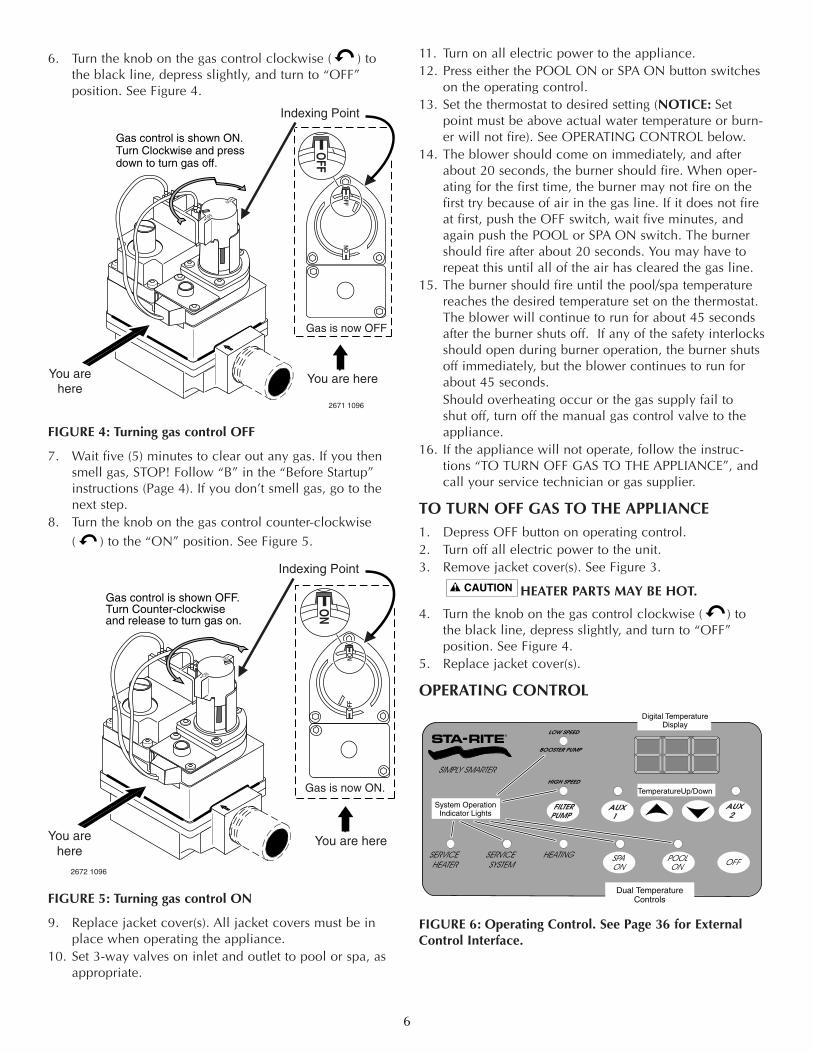
6. Turn the knob on the gas control clockwise ( ) tothe black line, depress slightly, and turn to “OFF” position. See Figure 4.
FIGURE 4: Turning gas control OFF
7. Wait five (5) minutes to clear out any gas. If you thensmell gas, STOP! Follow “B” in the “Before Startup”instructions (Page 4). If you don’t smell gas, go to thenext step.
8. Turn the knob on the gas control counter-clockwise( ) to the “ON” position. See Figure 5.
FIGURE 5: Turning gas control ON
9. Replace jacket cover(s). All jacket covers must be inplace when operating the appliance.
10. Set 3-way valves on inlet and outlet to pool or spa, asappropriate.
11. Turn on all electric power to the appliance.12. Press either the POOL ON or SPA ON button switches
on the operating control.13. Set the thermostat to desired setting (NOTICE: Set
point must be above actual water temperature or burn-er will not fire). See OPERATING CONTROL below.
14. The blower should come on immediately, and afterabout 20 seconds, the burner should fire. When oper-ating for the first time, the burner may not fire on thefirst try because of air in the gas line. If it does not fireat first, push the OFF switch, wait five minutes, andagain push the POOL or SPA ON switch. The burnershould fire after about 20 seconds. You may have torepeat this until all of the air has cleared the gas line.
15. The burner should fire until the pool/spa temperaturereaches the desired temperature set on the thermostat.The blower will continue to run for about 45 secondsafter the burner shuts off. If any of the safety interlocksshould open during burner operation, the burner shutsoff immediately, but the blower continues to run forabout 45 seconds. Should overheating occur or the gas supply fail to shut off, turn off the manual gas control valve to theappliance.
16. If the appliance will not operate, follow the instruc-tions “TO TURN OFF GAS TO THE APPLIANCE”, andcall your service technician or gas supplier.
TO TURN OFF GAS TO THE APPLIANCE1. Depress OFF button on operating control.2. Turn off all electric power to the unit.3. Remove jacket cover(s). See Figure 3.
HEATER PARTS MAY BE HOT.
4. Turn the knob on the gas control clockwise ( ) tothe black line, depress slightly, and turn to “OFF” position. See Figure 4.
5. Replace jacket cover(s).
OPERATING CONTROL
FIGURE 6: Operating Control. See Page 36 for ExternalControl Interface.
6
Indexing Point
Gas control is shown OFF.Turn Counter-clockwiseand release to turn gas on.
You arehere
You are here
OFF
ON
ON
Gas is now ON.
2672 1096
You arehere
You are here
Gas control is shown ON.Turn Clockwise and press down to turn gas off.
ON
OFF
OFF
Gas is now OFF
2671 1096
Indexing Point
Digital TemperatureDisplay
TemperatureUp/Down
Dual TemperatureControls
System OperationIndicator Lights
FILTERPUMP
AUX1
AUX2
HIGH SPEED
LOW SPEED
BOOSTER PUMP
The five operating switches are:
POOL ON Press this button to govern heater operation bythe pool temperature setting.SPA ON Press this button to govern heater operation by thespa temperature setting.OFF Press this button to switch off the heater.
▲TEMP Press this button to raise the temperature setting.
▼TEMP Press this button to lower the temperature setting. To toggle the display between degrees Centigrade (°C) anddegrees Fairenheit (°F):1. Turn the Operating Control OFF.2. Press ▲TEMP or ▼TEMP for 5 seconds. The display
will flash once and change modes (°C to °F or viceversa).
When either the ▲TEMP or ▼TEMP buttons are depressed,the digital display will indicate the temperature setting.After five seconds, the display will return to the actualpool/spa temperature.In addition to the digital temperature display, there are fiveindicator lights:The POOL ON light indicates that the pool water tempera-ture is governing operation of the heater.The SPA ON light indicates that the spa water temperatureis governing operation of the heater.The HEATING light comes on and stays on when the burn-er is firing. This light should be on whenever the burner ison. It blinks when the heater is calling for heat but not fir-ing. If this light is on but the burner fails to come on, oneof the “service” lights should come on, indicating a fault inthe system.The SERVICE SYSTEM light indicates that there is insufficientwater flow to the heater. If the pump is operating, this usual-ly indicates that the filter and/or skimmers should be cleaned(some filters may require backwashing). If the light remainson after the filter/skimmers have been serviced, the systemshould be checked by a qualified service technician.The SERVICE HEATER light indicates a fault in the heateror its controls. If this light comes on, shut down the heater(See TO TURN OFF GAS TO THE APPLIANCE, at left), andhave a qualified service technician check the system.
Risk of explosion or fire causing burns ordeath if safety interlocks are disabled. DO NOT attempt tooperate heater when SERVICE HEATER light is on or ifblower or burner will not start. Instead, follow instructionsunder “To Turn Off Gas to the Appliance”, at left, and calla qualified service technician to repair unit.
AFTER START-UPCHECKING WATER FLOW
Fire or flooding hazard. If the unit overheatsand the burner fails to shut off, follow instructions under“To Turn Off Gas to the Appliance”, Page 6, and call aqualified service technician to repair unit.
After start-up, the outlet water pipe should feel slightlywarmer than the inlet pipe. If it feels hot, or if you hear thewater in the heater boiling, there may not be enough waterflow to the appliance. Make sure that the filter is notplugged. If water temperature remains high but the unitcontinues to operate, turn off the appliance and call yourservice technician.
SPRING AND FALL OPERATION If the pool is only used occasionally, lower the pool ther-mostat to 65°F. and leave the heater on. This will keep thepool and the surrounding ground warm enough so that theheater should restore the pool to a comfortable tempera-ture within about one day.
COLD WEATHER OPERATIONThe heater may be operated in the wintertime, provided airtemperatures remain above freezing and the water tempera-ture is not permitted to drop below 65°F. Extended heateroperation with water temperatures below 65°F can result inserious damage to the heater and is not covered by warranty. NOTICE: When starting the heater for the swimming sea-son with a water temperature below 50°F, the heater maybe used to heat the water; however, make sure that theheater operates continuously until the water temperaturereaches the heater’s minimum setting of 65°F.During cold weather, if there is no danger of freezing,operate the filter pump continuously even if the heater isnot operating. If air temperatures are expected to dropbelow freezing (32°F), shut down the heater and winterizeit (See ”WINTERIZING”, Page 8). Allowing the heater tofreeze will void the warranty.
MAINTAINING POOL TEMPERATURETo maintain pool temperature, make sure that the heaterswitch and valving are reset to pool settings after using thespa.
ENERGY SAVING TIPS 1. Keep the pool or spa covered when not in use. This
will reduce heating costs, reduce water evaporation,conserve chemicals and reduce load on the filteringsystem.
2. Reduce pool thermostat to 78°F or lower; reduce spatemperature to 100°F.
3. Use a time clock to start the filter pump at 6 a.m. orlater. The swimming pool loses less heat after day-break.
4. For pools used only on weekends, lower the thermostatsetting by 10°F to 15°F during the week to reduce heatloss. A properly sized heater will restore normal tem-perature within one day.
5. Turn the heater off when the pool will not be used foran extended period.
6. Follow a regular program of preventive maintenancefor the heater each new swimming season. Checkoperation of the heater and its controls.
7
CARE AND MAINTENANCEMAINTENANCE INSTRUCTIONS
Risk of fire or explosion from flammablevapors. Do not store gasoline, cleaning fluids, varnishes,paints, or other volatile flammable liquids near heater or inthe same room with heater. The following maintenance is recommended every sixmonths and at the start of every swimming season:1. Inspect the jacket and venting system to make sure that
there are no obstructions to the flow of ventilating airor burner exhaust. On indoor heaters, check that roomair intakes are open and clear of obstructions.
2. Keep the area in and around the heater clear and freefrom combustible materials, gasoline and other flam-mable vapors and corrosive liquids.
3. On heaters equipped with a pressure relief valve, testthe operation of the valve by lifting the valve lever.
4. Test for proper operation of the pressure switch. (See“SWITCH SETTINGS” for testing instructions).
5. On indoor installations with high-temperature SpecialGas Vent systems, repeat the Final Installation Check,Page 15. Check for evidence of joint leakage. Makesure that joints have not slipped partially or completelyapart. Check pipe and fittings for cracks or breaks.
The combustion air blower is permanently lubricated,and does not require periodic lubrication. The burner doesnot require maintenance or adjustment by the user. Call aqualified service technician if you suspect that the burnermay require maintenance.
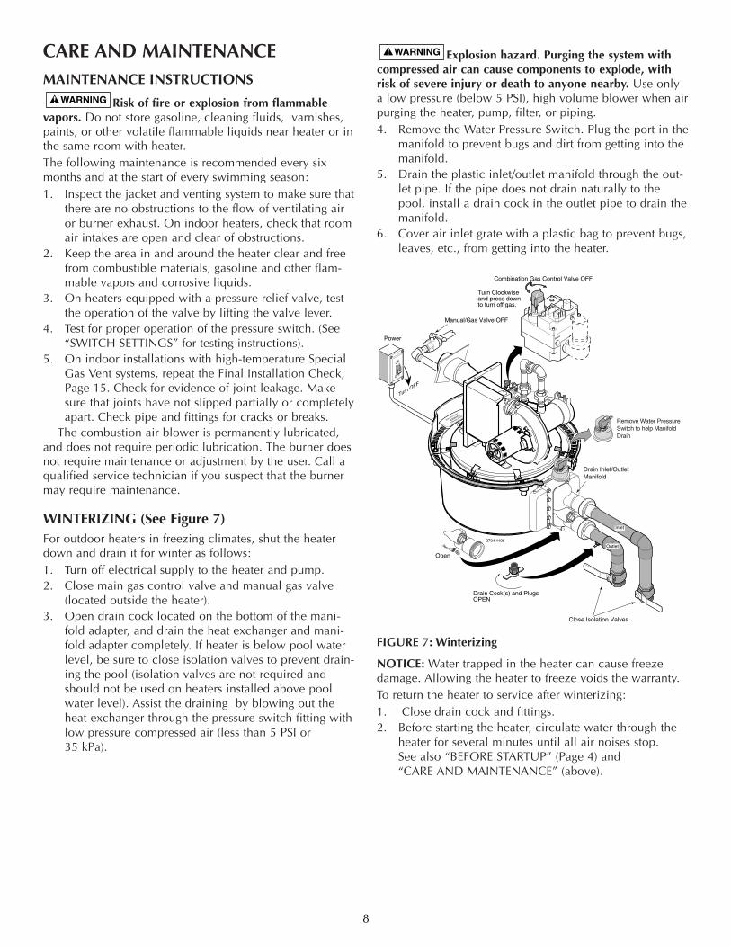
WINTERIZING (See Figure 7)For outdoor heaters in freezing climates, shut the heaterdown and drain it for winter as follows:1. Turn off electrical supply to the heater and pump.2. Close main gas control valve and manual gas valve
(located outside the heater).3. Open drain cock located on the bottom of the mani-
fold adapter, and drain the heat exchanger and mani-fold adapter completely. If heater is below pool waterlevel, be sure to close isolation valves to prevent drain-ing the pool (isolation valves are not required andshould not be used on heaters installed above poolwater level). Assist the draining by blowing out theheat exchanger through the pressure switch fitting withlow pressure compressed air (less than 5 PSI or 35 kPa).
Explosion hazard. Purging the system withcompressed air can cause components to explode, withrisk of severe injury or death to anyone nearby. Use onlya low pressure (below 5 PSI), high volume blower when airpurging the heater, pump, filter, or piping.4. Remove the Water Pressure Switch. Plug the port in the
manifold to prevent bugs and dirt from getting into themanifold.
5. Drain the plastic inlet/outlet manifold through the out-let pipe. If the pipe does not drain naturally to thepool, install a drain cock in the outlet pipe to drain themanifold.
6. Cover air inlet grate with a plastic bag to prevent bugs,leaves, etc., from getting into the heater.
FIGURE 7: Winterizing
NOTICE: Water trapped in the heater can cause freezedamage. Allowing the heater to freeze voids the warranty.To return the heater to service after winterizing:1. Close drain cock and fittings.2. Before starting the heater, circulate water through the
heater for several minutes until all air noises stop. See also “BEFORE STARTUP” (Page 4) and “CARE AND MAINTENANCE” (above).
8
PRESS
TAB
VENT
PILOT
OFFOFF
ONON
Open
Manual/Gas Valve OFF
Power
Combination Gas Control Valve OFF
Close Isolation Valves
Turn Clockwiseand press downto turn off gas.
Drain Cock(s) and PlugsOPEN
2704 1196
PRESS
TAB
VENT
PILOT
OF
FO
FF
ONO
N
Remove Water PressureSwitch to help ManifoldDrain
Outlet
Inlet
Drain Inlet/Outlet Manifold
INSTALLATION INSTRUCTIONSRisk of fire, explosion, or asphyxiation if heater
is improperly installed, adjusted, serviced or maintained.These instructions are for licensed, certified, trained andexperienced installers only. Be sure your installer or servicetechnician holds all required licenses or certification foryour area. Attempts by unqualified persons to service orrepair this heater are dangerous and could be fatal.
PUTTING THE HEATER INTO SERVICEIf the heater is installed below the level of the pool, ormore than two feet above pool level, the pressure switchsetting should be adjusted. See PRESSURE SWITCH, in theMAINTENANCE section.Before putting the heater into service for the first time, fol-low the instructions under BEFORE STARTUP in the frontof this manual. Check for proper operation of the heater byfollowing the steps under OPERATING INSTRUCTIONS. Damage to equipment caused by improper installation orrepair will void the warranty.
OUTDOOR INSTALLATION INSTRUCTIONSFor heaters located outdoors, using the built-in stacklessventing system.
Risk of explosion if an LP (propane) gas unit isinstalled in a pit or other low spot. LP gas is heavier thanair. Do not install the heater using LP gas in pits or otherlocations where gas might collect. Consult your local build-ing code officials to determine installation requirements ofheater relative to LP gas storage tanks and filling equipment.Installation must meet the requirements of the Standard forthe Storage and Handling of Liquid Petroleum Gases,ANSI/NFPA 58 (latest edition). Consult local codes and fire pro-tection authorities about specific installation restrictions.
Locate the heater on a level surface in an open area that isprotected from drainage or run-off. Install the heater in anarea where leaves or other debris will not collect on oraround the heater. Do not install the heater where water(including sprinklers or runoff) will fall directly onto thejacket.
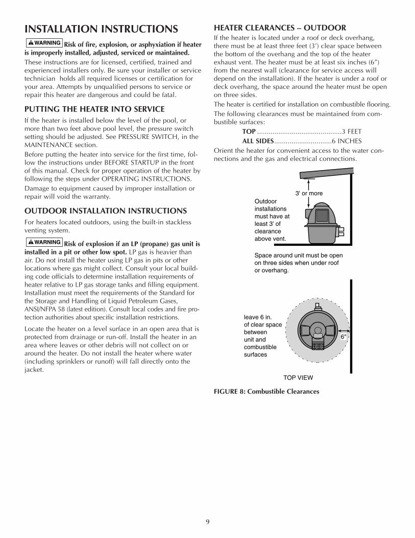
HEATER CLEARANCES – OUTDOORIf the heater is located under a roof or deck overhang,there must be at least three feet (3’) clear space betweenthe bottom of the overhang and the top of the heaterexhaust vent. The heater must be at least six inches (6”)from the nearest wall (clearance for service access willdepend on the installation). If the heater is under a roof ordeck overhang, the space around the heater must be openon three sides.The heater is certified for installation on combustible flooring.The following clearances must be maintained from com-bustible surfaces:
TOP ............................................3 FEETALL SIDES..............................6 INCHES
Orient the heater for convenient access to the water con-nections and the gas and electrical connections.
FIGURE 8: Combustible Clearances
9
Outdoor installationsmust have atleast 3' ofclearanceabove vent.
leave 6 in.of clear spacebetweenunit andcombustiblesurfaces
TOP VIEW
6"
3' or more
Space around unit must be open on three sides when under roofor overhang.
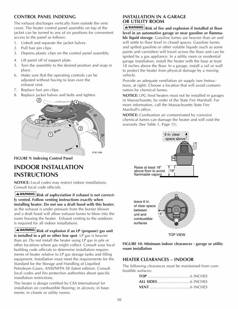
CONTROL PANEL INDEXINGThe exhaust discharges vertically from outside the ventcover. The heater control panel assembly on top of thejacket can be turned to any of six positions for convenientaccess to the panel as follows:1. Unbolt and separate the jacket halves.2. Pull hair pin clips.3. Depress plastic clips on the control panel assembly.
4. Lift panel off of support plate.5. Turn the assembly to the desired position and snap in
place.6. Make sure that the operating controls can be
adjusted without having to lean over the exhaust vent.
7. Replace hair pin clips.8. Replace jacket halves and bolts and tighten.
FIGURE 9: Indexing Control Panel
INDOOR INSTALLATION INSTRUCTIONSNOTICE: Local codes may restrict indoor installations.Consult local code officials.
Risk of asphyxiation if exhaust is not correct-ly vented. Follow venting instructions exactly wheninstalling heater. Do not use a draft hood with this heater,as the exhaust is under pressure from the burner blowerand a draft hood will allow exhaust fumes to blow into theroom housing the heater. Exhaust venting to the outdoorsis required for all indoor installations.
Risk of explosion if an LP (propane) gas unitis installed in a pit or other low spot. LP gas is heavierthan air. Do not install the heater using LP gas in pits orother locations where gas might collect. Consult your localbuilding code officials to determine installation require-ments of heater relative to LP gas storage tanks and fillingequipment. Installation must meet the requirements for theStandard for the Storage and Handling of LiquifiedPetroleum Gases, ANSI/NFPA 58 (latest edition). Consultlocal codes and fire protection authorities about specificinstallation restrictions.The heater is design certified by CSA International forinstallation on combustible flooring; in alcoves; in base-ments; in closets or utility rooms.
INSTALLATION IN A GARAGE OR UTILITY ROOM
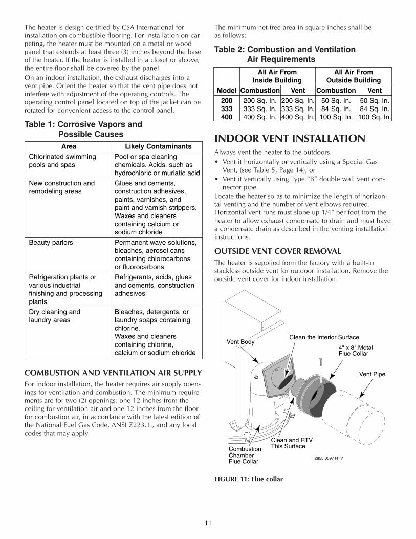
Risk of fire and explosion if installed at floorlevel in an automotive garage or near gasoline or flamma-ble liquid storage. Gasoline fumes are heavier than air andwill settle to floor level in closed spaces. Gasoline fumesand spilled gasoline or other volatile liquids (such as somepaints and varnishes) will travel across the floor and can beignited by a gas appliance. In a utility room or residentialgarage installation, install the heater with the base at least18 inches above the floor. In a garage, install a rail or wallto protect the heater from physical damage by a movingvehicle.Provide an adequate ventilation air supply (see Instruc-tions, at right). Choose a location that will avoid contami-nation by chemical fumes. NOTICE: LPG fired heaters must not be installed in garagesin Massachusetts, by order of the State Fire Marshall. Formore information, call the Massachusetts State FireMarshall’s office.NOTICE: Combustion air contaminated by corrosive chemical fumes can damage the heater and will void thewarranty (See Table 1, Page 11).
FIGURE 10: Minimum indoor clearances - garage or utilityroom installation
HEATER CLEARANCES – INDOORThe following clearances must be maintained from com-bustible surfaces:
TOP .......................................6 INCHESALL SIDES..............................6 INCHESVENT .....................................6 INCHES
10
6 in. clear space above
leave 6 in.of clear spacebetweenunit andcombustiblesurfaces
TOP VIEW
6"
Raise at least 18"above floor to avoidflammable vapors
18"
45
1
2
2732 1296
FILTERPUMP AUX1
AUX2
HIGH SPEED
LOW SPEED BOOSTER PUMP
3
The heater is design certified by CSA International forinstallation on combustible flooring. For installation on car-peting, the heater must be mounted on a metal or woodpanel that extends at least three (3) inches beyond the baseof the heater. If the heater is installed in a closet or alcove,the entire floor shall be covered by the panel. On an indoor installation, the exhaust discharges into avent pipe. Orient the heater so that the vent pipe does notinterfere with adjustment of the operating controls. Theoperating control panel located on top of the jacket can berotated for convenient access to the control panel.
Table 1: Corrosive Vapors and Possible Causes
COMBUSTION AND VENTILATION AIR SUPPLYFor indoor installation, the heater requires air supply open-ings for ventilation and combustion. The minimum require-ments are for two (2) openings: one 12 inches from theceiling for ventilation air and one 12 inches from the floorfor combustion air, in accordance with the latest edition ofthe National Fuel Gas Code, ANSI Z223.1., and any localcodes that may apply.
The minimum net free area in square inches shall be as follows:
Table 2: Combustion and VentilationAir Requirements
INDOOR VENT INSTALLATIONAlways vent the heater to the outdoors. • Vent it horizontally or vertically using a Special Gas
Vent, (see Table 5, Page 14), or • Vent it vertically using Type “B” double wall vent con-
nector pipe. Locate the heater so as to minimize the length of horizon-tal venting and the number of vent elbows required.Horizontal vent runs must slope up 1/4” per foot from theheater to allow exhaust condensate to drain and must havea condensate drain as described in the venting installationinstructions.
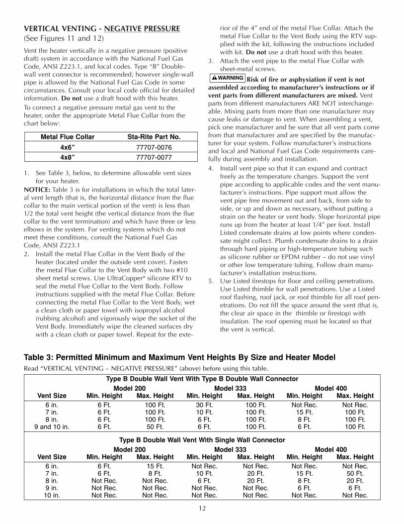
OUTSIDE VENT COVER REMOVALThe heater is supplied from the factory with a built-instackless outside vent for outdoor installation. Remove theoutside vent cover for indoor installation.
FIGURE 11: Flue collar
11
Area Likely Contaminants
Chlorinated swimming Pool or spa cleaning pools and spas chemicals. Acids, such as
hydrochloric or muriatic acid
New construction and Glues and cements, remodeling areas construction adhesives,
paints, varnishes, and paint and varnish strippers.Waxes and cleanerscontaining calcium or sodium chloride
Beauty parlors Permanent wave solutions,bleaches, aerosol canscontaining chlorocarbons or fluorocarbons
Refrigeration plants or Refrigerants, acids, glues various industrial and cements, constructionfinishing and processing adhesivesplants
Dry cleaning and Bleaches, detergents, or laundry areas laundry soaps containing
chlorine. Waxes and cleanerscontaining chlorine, calcium or sodium chloride
All Air From All Air FromInside Building Outside Building
Model Combustion Vent Combustion Vent
200 200 Sq. In. 200 Sq. In. 50 Sq. In. 50 Sq. In. 333 333 Sq. In. 333 Sq. In. 84 Sq. In. 84 Sq. In.400 400 Sq. In. 400 Sq. In. 100 Sq. In. 100 Sq. In.
CombustionChamberFlue Collar
4" x 8" Metal Flue Collar
Vent Body
2855 0597 RTV
Clean the Interior Surface
Vent Pipe
Clean and RTV This Surface
VERTICAL VENTING - NEGATIVE PRESSURE(See Figures 11 and 12)
Vent the heater vertically in a negative pressure (positivedraft) system in accordance with the National Fuel GasCode, ANSI Z223.1, and local codes. Type “B” Double-wall vent connector is recommended; however single-wallpipe is allowed by the National Fuel Gas Code in somecircumstances. Consult your local code official for detailedinformation. Do not use a draft hood with this heater.To connect a negative pressure metal gas vent to theheater, order the appropriate Metal Flue Collar from thechart below:
1. See Table 3, below, to determine allowable vent sizesfor your heater.
NOTICE: Table 3 is for installations in which the total later-al vent length (that is, the horizontal distance from the fluecollar to the main vertical portion of the vent) is less than1/2 the total vent height (the vertical distance from the fluecollar to the vent termination) and which have three or lesselbows in the system. For venting systems which do notmeet these conditions, consult the National Fuel GasCode, ANSI Z223.1 2. Install the metal Flue Collar in the Vent Body of the
heater (located under the outside vent cover). Fastenthe metal Flue Collar to the Vent Body with two #10sheet metal screws. Use UltraCopper® silicone RTV toseal the metal Flue Collar to the Vent Body. Followinstructions supplied with the metal Flue Collar. Beforeconnecting the metal Flue Collar to the Vent Body, weta clean cloth or paper towel with isopropyl alcohol(rubbing alcohol) and vigorously wipe the socket of theVent Body. Immediately wipe the cleaned surfaces drywith a clean cloth or paper towel. Repeat for the exte-
rior of the 4” end of the metal Flue Collar. Attach themetal Flue Collar to the Vent Body using the RTV sup-plied with the kit, following the instructions includedwith kit. Do not use a draft hood with this heater.
3. Attach the vent pipe to the metal Flue Collar withsheet-metal screws.
Risk of fire or asphyxiation if vent is notassembled according to manufacturer’s instructions or ifvent parts from different manufacturers are mixed. Ventparts from different manufacturers ARE NOT interchange-able. Mixing parts from more than one manufacturer maycause leaks or damage to vent. When assembling a vent,pick one manufacturer and be sure that all vent parts comefrom that manufacturer and are specified by the manufac-turer for your system. Follow manufacturer’s instructionsand local and National Fuel Gas Code requirements care-fully during assembly and installation. 4. Install vent pipe so that it can expand and contract
freely as the temperature changes. Support the ventpipe according to applicable codes and the vent manu-facturer’s instructions. Pipe support must allow thevent pipe free movement out and back, from side toside, or up and down as necessary, without putting astrain on the heater or vent body. Slope horizontal piperuns up from the heater at least 1/4” per foot. InstallListed condensate drains at low points where conden-sate might collect. Plumb condensate drains to a drainthrough hard piping or high-temperature tubing suchas silicone rubber or EPDM rubber – do not use vinylor other low temperature tubing. Follow drain manu-facturer’s installation instructions.
5. Use Listed firestops for floor and ceiling penetrations.Use Listed thimble for wall penetrations. Use a Listedroof flashing, roof jack, or roof thimble for all roof pen-etrations. Do not fill the space around the vent (that is,the clear air space in the thimble or firestop) withinsulation. The roof opening must be located so thatthe vent is vertical.
12
Table 3: Permitted Minimum and Maximum Vent Heights By Size and Heater ModelRead “VERTICAL VENTING – NEGATIVE PRESSURE” (above) before using this table.
Type B Double Wall Vent With Type B Double Wall ConnectorModel 200 Model 333 Model 400
Vent Size Min. Height Max. Height Min. Height Max. Height Min. Height Max. Height6 in. 6 Ft. 100 Ft. 30 Ft. 100 Ft. Not Rec. Not Rec.7 in. 6 Ft. 100 Ft. 10 Ft. 100 Ft. 15 Ft. 100 Ft.8 in. 6 Ft. 100 Ft. 6 Ft. 100 Ft. 8 Ft. 100 Ft.
9 and 10 in. 6 Ft. 50 Ft. 6 Ft. 100 Ft. 6 Ft. 100 Ft.
Type B Double Wall Vent With Single Wall ConnectorModel 200 Model 333 Model 400
Vent Size Min. Height Max. Height Min. Height Max. Height Min. Height Max. Height6 in. 6 Ft. 15 Ft. Not Rec. Not Rec. Not Rec. Not Rec.7 in. 6 Ft. 8 Ft. 10 Ft. 20 Ft. 15 Ft. 50 Ft.8 in. Not Rec. Not Rec. 6 Ft. 20 Ft. 8 Ft. 20 Ft.9 in. Not Rec. Not Rec. Not Rec. Not Rec. 6 Ft. 6 Ft.10 in. Not Rec. Not Rec. Not Rec. Not Rec. Not Rec. Not Rec.
Metal Flue Collar Sta-Rite Part No.
4x6” 77707-0076
4x8” 77707-0077
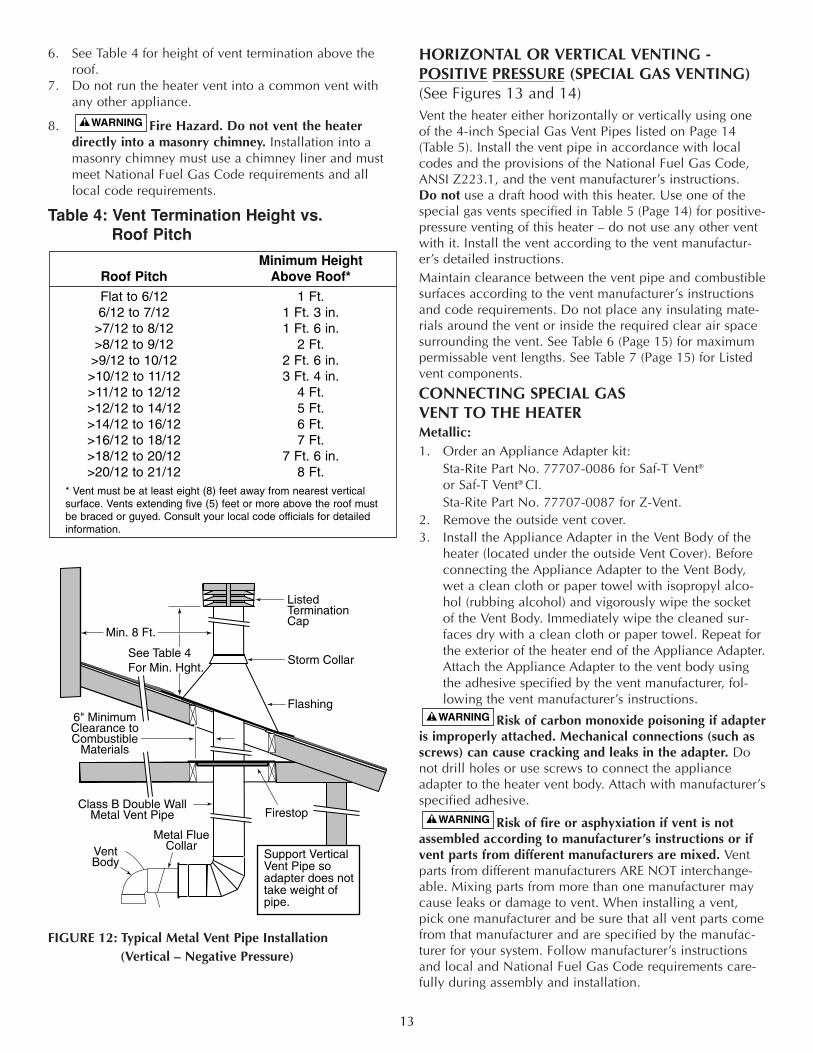
6. See Table 4 for height of vent termination above theroof.
7. Do not run the heater vent into a common vent withany other appliance.
8. Fire Hazard. Do not vent the heaterdirectly into a masonry chimney. Installation into amasonry chimney must use a chimney liner and mustmeet National Fuel Gas Code requirements and alllocal code requirements.
Table 4: Vent Termination Height vs.Roof Pitch
FIGURE 12: Typical Metal Vent Pipe Installation(Vertical – Negative Pressure)
HORIZONTAL OR VERTICAL VENTING -POSITIVE PRESSURE (SPECIAL GAS VENTING)(See Figures 13 and 14)Vent the heater either horizontally or vertically using oneof the 4-inch Special Gas Vent Pipes listed on Page 14(Table 5). Install the vent pipe in accordance with localcodes and the provisions of the National Fuel Gas Code,ANSI Z223.1, and the vent manufacturer’s instructions. Do not use a draft hood with this heater. Use one of thespecial gas vents specified in Table 5 (Page 14) for positive-pressure venting of this heater – do not use any other ventwith it. Install the vent according to the vent manufactur-er’s detailed instructions. Maintain clearance between the vent pipe and combustiblesurfaces according to the vent manufacturer’s instructionsand code requirements. Do not place any insulating mate-rials around the vent or inside the required clear air spacesurrounding the vent. See Table 6 (Page 15) for maximumpermissable vent lengths. See Table 7 (Page 15) for Listedvent components.
CONNECTING SPECIAL GAS VENT TO THE HEATERMetallic:1. Order an Appliance Adapter kit:
Sta-Rite Part No. 77707-0086 for Saf-T Vent®
or Saf-T Vent® CI.Sta-Rite Part No. 77707-0087 for Z-Vent.
2. Remove the outside vent cover. 3. Install the Appliance Adapter in the Vent Body of the
heater (located under the outside Vent Cover). Beforeconnecting the Appliance Adapter to the Vent Body,wet a clean cloth or paper towel with isopropyl alco-hol (rubbing alcohol) and vigorously wipe the socketof the Vent Body. Immediately wipe the cleaned sur-faces dry with a clean cloth or paper towel. Repeat forthe exterior of the heater end of the Appliance Adapter.Attach the Appliance Adapter to the vent body usingthe adhesive specified by the vent manufacturer, fol-lowing the vent manufacturer’s instructions.
Risk of carbon monoxide poisoning if adapteris improperly attached. Mechanical connections (such asscrews) can cause cracking and leaks in the adapter. Donot drill holes or use screws to connect the applianceadapter to the heater vent body. Attach with manufacturer’sspecified adhesive.
Risk of fire or asphyxiation if vent is notassembled according to manufacturer’s instructions or ifvent parts from different manufacturers are mixed. Ventparts from different manufacturers ARE NOT interchange-able. Mixing parts from more than one manufacturer maycause leaks or damage to vent. When installing a vent,pick one manufacturer and be sure that all vent parts comefrom that manufacturer and are specified by the manufac-turer for your system. Follow manufacturer’s instructionsand local and National Fuel Gas Code requirements care-fully during assembly and installation.
13
Minimum HeightRoof Pitch Above Roof*
Flat to 6/12 1 Ft.6/12 to 7/12 1 Ft. 3 in.
>7/12 to 8/12 1 Ft. 6 in.>8/12 to 9/12 2 Ft.>9/12 to 10/12 2 Ft. 6 in.>10/12 to 11/12 3 Ft. 4 in.>11/12 to 12/12 4 Ft.>12/12 to 14/12 5 Ft.>14/12 to 16/12 6 Ft.>16/12 to 18/12 7 Ft.>18/12 to 20/12 7 Ft. 6 in.>20/12 to 21/12 8 Ft.
* Vent must be at least eight (8) feet away from nearest verticalsurface. Vents extending five (5) feet or more above the roof mustbe braced or guyed. Consult your local code officials for detailedinformation.
6" MinimumClearance toCombustible
Materials
ListedTermination Cap
Storm Collar
Flashing
Firestop
VentBody
Metal FlueCollar
Class B Double WallMetal Vent Pipe
See Table 4For Min. Hght.
Min. 8 Ft.
Support Vertical Vent Pipe so adapter does not take weight of pipe.
4. Install vent pipe so that it can expand and contractfreely as the temperature changes. Support the ventpipe according to applicable codes and vent manufac-turer’s instructions. Pipe support must allow the ventpipe free movement out and back, from side to side, orup and down as necessary, without putting a strain onthe heater or vent body. Slope horizontal pipe runs upfrom the heater at least 1/4” per foot. Install Listed con-densate drains at low points where condensate mightcollect. Plumb condensate drains to a drain throughhard piping or high-temperature tubing such as sili-cone rubber or EPDM rubber – do not use vinyl orother low temperature tubing. Follow drain manufac-turer’s installation instructions.
5. Use Listed firestops for floor and ceiling penetrations.Use Listed thimble for wall penetrations. Use a Listedroof flashing, roof jack, or roof thimble for all roof pen-etrations. Do not fill the space around the vent (that is,
the clear air space in the thimble or firestop) withinsulation. The roof opening must be located so thatthe vent is vertical.
6. Vent Termination – Vertical (See Table 4, Page 13, forheight of vent termination above the roof. See Table 7,Page 15, for Listed terminations.) Use a Listed vent ter-minal specified by local and national codes and yourmanufacturer’s instructions. A roof termination must bevertical.
7. Vent Termination – Horizontal (See Table 7). Use a list-ed wall thimble and vent terminal from Table 7.
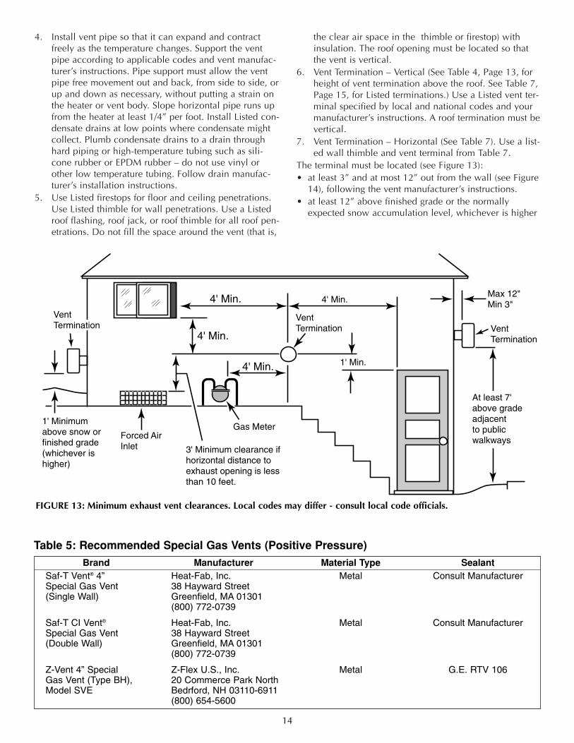
The terminal must be located (see Figure 13):• at least 3” and at most 12” out from the wall (see Figure
14), following the vent manufacturer’s instructions.• at least 12” above finished grade or the normally
expected snow accumulation level, whichever is higher
14
Brand Manufacturer Material Type SealantSaf-T Vent® 4” Heat-Fab, Inc. Metal Consult ManufacturerSpecial Gas Vent 38 Hayward Street(Single Wall) Greenfield, MA 01301
(800) 772-0739
Saf-T CI Vent® Heat-Fab, Inc. Metal Consult ManufacturerSpecial Gas Vent 38 Hayward Street(Double Wall) Greenfield, MA 01301
(800) 772-0739
Z-Vent 4” Special Z-Flex U.S., Inc. Metal G.E. RTV 106Gas Vent (Type BH), 20 Commerce Park NorthModel SVE Bedrford, NH 03110-6911
(800) 654-5600
Table 5: Recommended Special Gas Vents (Positive Pressure)
1' Min.
4' Min.4' Min.
4' Min.
4' Min.
3' Minimum clearance ifhorizontal distance toexhaust opening is lessthan 10 feet.
Forced AirInlet
VentTermination
1' Minimumabove snow orfinished grade(whichever ishigher)
At least 7' above grade adjacent to publicwalkways
VentTermination Vent
Termination
Gas Meter
Max 12"Min 3"
FIGURE 13: Minimum exhaust vent clearances. Local codes may differ - consult local code officials.
• at least 4 feet below or horizontally from, or 1 footabove, any doors or windows or gravity air inlet to abuilding
• At least 3 feet above any forced air inlet located within10 feet
• At least 4 feet horizontally from electric meters, gasmeters, regulators and relief equipment
• At least 7 feet above grade adjacent to walkways or sim-ilar traffic areas.
Allow at least 3 feet vertical clearance over vent termina-tion when terminating under an overhang or deck.Avoid corners or alcoves where snow or wind could havean effect. Exhaust may affect shrubbery and some buildingmaterials. Keep shrubbery away from termination. To pre-vent staining or deterioration, sealing or shielding exposedsurfaces may be required.
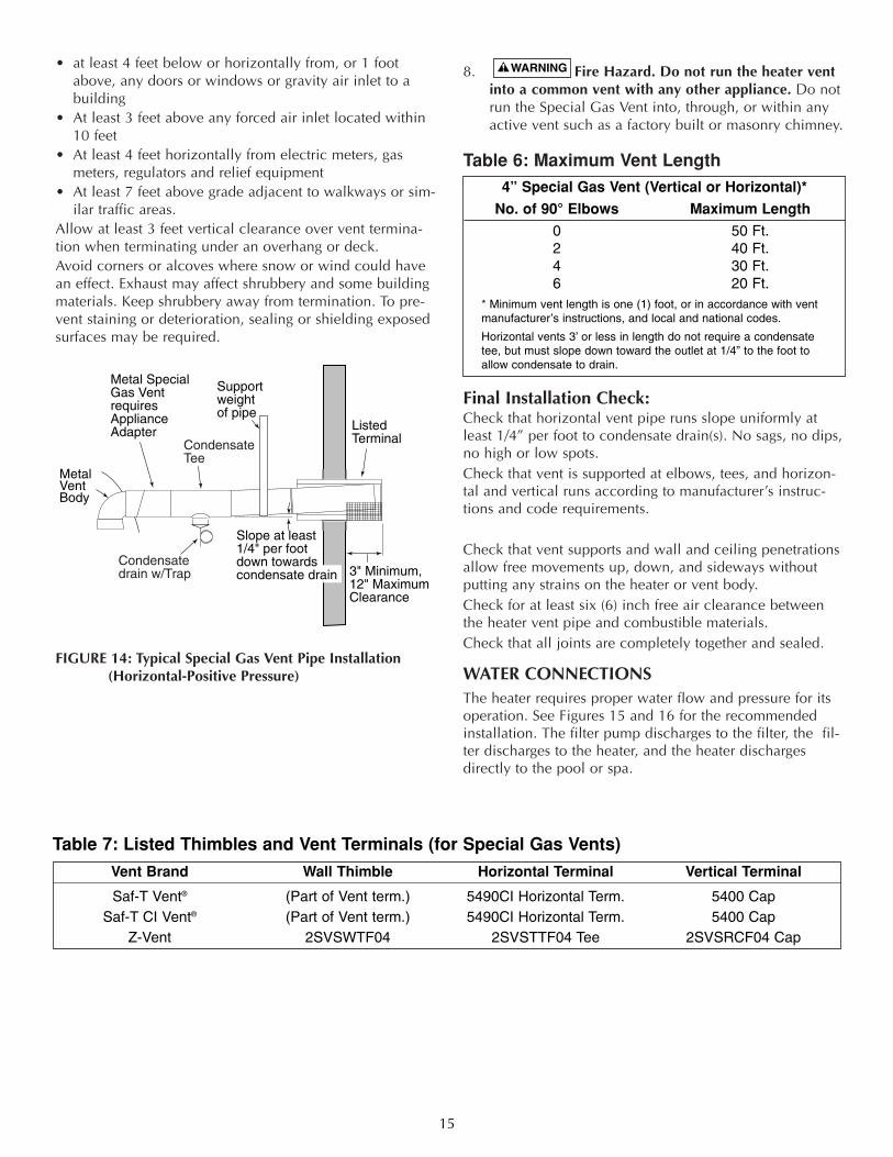
FIGURE 14: Typical Special Gas Vent Pipe Installation(Horizontal-Positive Pressure)
8. Fire Hazard. Do not run the heater ventinto a common vent with any other appliance. Do notrun the Special Gas Vent into, through, or within anyactive vent such as a factory built or masonry chimney.
Table 6: Maximum Vent Length
Final Installation Check:Check that horizontal vent pipe runs slope uniformly atleast 1/4” per foot to condensate drain(s). No sags, no dips,no high or low spots. Check that vent is supported at elbows, tees, and horizon-tal and vertical runs according to manufacturer’s instruc-tions and code requirements.
Check that vent supports and wall and ceiling penetrationsallow free movements up, down, and sideways withoutputting any strains on the heater or vent body.Check for at least six (6) inch free air clearance betweenthe heater vent pipe and combustible materials.Check that all joints are completely together and sealed.
WATER CONNECTIONSThe heater requires proper water flow and pressure for itsoperation. See Figures 15 and 16 for the recommendedinstallation. The filter pump discharges to the filter, the fil-ter discharges to the heater, and the heater dischargesdirectly to the pool or spa.
15
Vent Brand Wall Thimble Horizontal Terminal Vertical Terminal
Saf-T Vent® (Part of Vent term.) 5490CI Horizontal Term. 5400 CapSaf-T CI Vent® (Part of Vent term.) 5490CI Horizontal Term. 5400 Cap
Z-Vent 2SVSWTF04 2SVSTTF04 Tee 2SVSRCF04 Cap
Table 7: Listed Thimbles and Vent Terminals (for Special Gas Vents)
4” Special Gas Vent (Vertical or Horizontal)*
No. of 90° Elbows Maximum Length
0 50 Ft.2 40 Ft.4 30 Ft.6 20 Ft.
* Minimum vent length is one (1) foot, or in accordance with vent manufacturer’s instructions, and local and national codes.
Horizontal vents 3’ or less in length do not require a condensatetee, but must slope down toward the outlet at 1/4” to the foot toallow condensate to drain.
Condensate drain w/Trap
Condensate Tee
2787 0297
Slope at least 1/4" per footdown towards condensate drain
Support weightof pipe
ListedTerminal
3" Minimum,12" MaximumClearance
Metal Special Gas VentrequiresApplianceAdapter
MetalVentBody
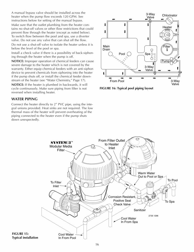
A manual bypass valve should be installed across theheater when the pump flow exceeds 120 GPM. Seeinstructions below for setting of the manual bypass.Make sure that the outlet plumbing from the heater con-tains no shut-off valves or other flow restrictions that couldprevent flow through the heater (except as noted below).To switch flow between the pool and spa, use a divertervalve. Do not use any valve that can shut off the flow. Do not use a shut-off valve to isolate the heater unless it isbelow the level of the pool or spa. Install a check valve if there is a possibility of back-siphon-ing through the heater when the pump is off. NOTICE: Improper operation of chemical feeders can causesevere damage to the heater which is not covered by thewarranty. Either equip chemical feeders with an anti-siphondevice to prevent chemicals from siphoning into the heaterif the pump shuts off, or install the chemical feeder down-stream of the heater (see “Water Chemistry,” Page 17).NOTICE: If the heater is plumbed in backwards, it willcycle continuously. Make sure piping from filter is notreversed when installing heater.
WATER PIPINGConnect the heater directly to 2” PVC pipe, using the inte-gral unions provided. Heat sinks are not required. The lowthermal mass of the heater will prevent overheating of thepiping connected to the heater even if the pump shutsdown unexpectedly.
16
Cool Water In From Spa
2735 1296
From Filter Outletto Heater
Inlet
Warm WaterOut to Pool or Spa
Sanitizer
Corrosion Resistant,Positive SealCheck Valve
To FilterInlet
Cool Water In From Pool
To Spa
To Pool
SYSTEM 3™
Modular MediaFilter
FIGURE 15:Typical installation
Pool
MainDrain
Spa
From Pool
3-WayValve
3-WayValve
3-WayValve
Chlorinator
Heater
Filter
Pump
FIGURE 16: Typical pool piping layout
17
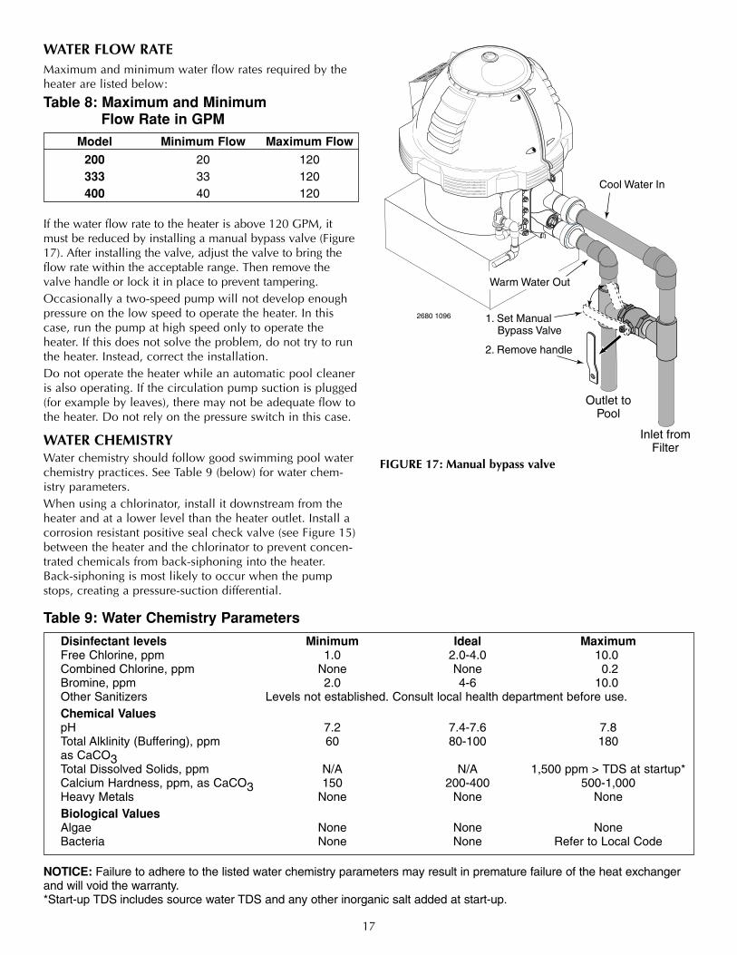
WATER FLOW RATEMaximum and minimum water flow rates required by theheater are listed below:
Table 8: Maximum and Minimum Flow Rate in GPM
If the water flow rate to the heater is above 120 GPM, itmust be reduced by installing a manual bypass valve (Figure17). After installing the valve, adjust the valve to bring theflow rate within the acceptable range. Then remove thevalve handle or lock it in place to prevent tampering.Occasionally a two-speed pump will not develop enoughpressure on the low speed to operate the heater. In thiscase, run the pump at high speed only to operate theheater. If this does not solve the problem, do not try to runthe heater. Instead, correct the installation.Do not operate the heater while an automatic pool cleaneris also operating. If the circulation pump suction is plugged(for example by leaves), there may not be adequate flow tothe heater. Do not rely on the pressure switch in this case.
WATER CHEMISTRYWater chemistry should follow good swimming pool waterchemistry practices. See Table 9 (below) for water chem-istry parameters.When using a chlorinator, install it downstream from theheater and at a lower level than the heater outlet. Install acorrosion resistant positive seal check valve (see Figure 15)between the heater and the chlorinator to prevent concen-trated chemicals from back-siphoning into the heater.Back-siphoning is most likely to occur when the pumpstops, creating a pressure-suction differential.
FIGURE 17: Manual bypass valve
Model Minimum Flow Maximum Flow
200 20 120333 33 120400 40 120
Table 9: Water Chemistry Parameters
Disinfectant levels Minimum Ideal MaximumFree Chlorine, ppm 1.0 2.0-4.0 10.0Combined Chlorine, ppm None None 0.2Bromine, ppm 2.0 4-6 10.0Other Sanitizers Levels not established. Consult local health department before use.Chemical ValuespH 7.2 7.4-7.6 7.8Total Alklinity (Buffering), ppm 60 80-100 180as CaCO3Total Dissolved Solids, ppm N/A N/A 1,500 ppm > TDS at startup*Calcium Hardness, ppm, as CaCO3 150 200-400 500-1,000Heavy Metals None None NoneBiological ValuesAlgae None None NoneBacteria None None Refer to Local Code
1. Set Manual Bypass Valve
2. Remove handle
Cool Water In
Warm Water Out
2680 1096
Inlet fromFilter
Outlet toPool
NOTICE: Failure to adhere to the listed water chemistry parameters may result in premature failure of the heat exchangerand will void the warranty.*Start-up TDS includes source water TDS and any other inorganic salt added at start-up.
18
WATER PRESSURE SWITCHHazardous pressure. Do not bypass the Water
Pressure Switch or render it inoperable.
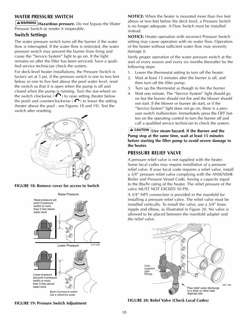
Switch SettingsThe water pressure switch turns off the burner if the waterflow is interrupted. If the water flow is restricted, the waterpressure switch may prevent the burner from firing andcause the “Service System” light to go on. If the lightremains on after the filter has been serviced, have a quali-fied service technician check the system. For deck-level heater installations, the Pressure Switch isfactory set at 3 psi. If the pressure switch is one to two feetbelow or one to five feet above the pool water level, resetthe switch so that it is open when the pump is off andclosed when the pump is running. Turn the star-wheel onthe switch clockwise ( ) to raise setting (heater belowthe pool) and counterclockwise ( ) to lower the setting(heater above the pool - see Figures 18 and 19). Test theswitch after resetting.
FIGURE 18: Remove cover for access to Switch
FIGURE 19: Pressure Switch Adjustment
NOTICE: When the heater is mounted more than five feetabove or two feet below the deck level, a Pressure Switchis no longer adequate. A Flow Switch must be installedinstead.NOTICE: Heater operation with incorrect Pressure Switchsetting may cause operation with no water flow. Operationof the heater without sufficient water flow may severelydamage it.Verify proper operation of the water pressure switch at thestart of every season and every six months thereafter by thefollowing steps:1. Lower the thermostat setting to turn off the heater.2. Wait at least 15 minutes after the burner is off, and
then turn off the filter pump. 3. Turn up the thermostat as though to fire the burner. 4. Wait one minute. The “Service System” light should go
on but the burner should not fire and the blower shouldnot start. If the blower or burner do start, or if the“Service System” light does not go on, there is a pres-sure switch malfunction. Immediately press the OFF but-ton on the operating control to turn the burner off andcall a qualified service technician to check the system.
Live steam hazard. If the Burner and thePump stop at the same time, wait at least 15 minutesbefore starting the filter pump to avoid severe damage tothe heater.
PRESSURE RELIEF VALVEA pressure relief valve is not supplied with the heater.Some local codes may require installation of a pressurerelief valve. If your local code requires a relief valve, installa 3/4” pressure relief valve complying with the ANSI/ASMEBoiler and Pressure Vessel Code, having a capacity equalto the Btu/hr rating of the heater. The relief pressure of thevalve MUST NOT EXCEED 50 PSI.A 3/4” NPT connection is provided in the manifold forinstalling a pressure relief valve. The relief valve must beinstalled vertically. To install the valve, use a 3/4” brassnipple and elbow, as illustrated in Figure 20. No valve isallowed to be placed between the manifold adapter andthe relief valve.
FIGURE 20: Relief Valve (Check Local Codes)
Pipe relief valve dischargeto a drain or other safe disposal site.
2681 1096
Relief Valve Installed
Usersuppliedpipefittings
2734 1296Lower Pressure
Raise Pressure
Raise pressure set point if pressureswitch is more than 2 feet below water level
Lower pressure set point if pressure switch is more than 5 feet above water level
Back of pressure switch has a reference scale.
19
To avoid water damage or scalding from operation of therelief valve, install a drain pipe in the outlet of the pressurerelief valve that will direct water discharging from thevalve to a safe place for disposal. Do not install any reduc-ing couplings or valves in the drain pipe. The drain pipemust be installed so as to allow complete drainage fromthe valve and drain line. The relief valve should be testedat least once a year by lifting the valve lever.
Explosion hazard. Any heater installed withrestrictive devices in the piping system downstream fromthe heater (including check valves, isolation valves, flownozzles, or therapeutic pool valving) must have a reliefvalve installed as described above. See Page 16.
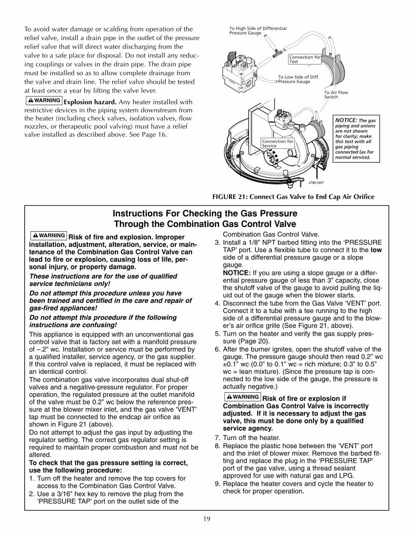
Risk of fire and explosion. Improperinstallation, adjustment, alteration, service, or main-tenance of the Combination Gas Control Valve canlead to fire or explosion, causing loss of life, per-sonal injury, or property damage.These instructions are for the use of qualified service technicians only!Do not attempt this procedure unless you havebeen trained and certified in the care and repair ofgas-fired appliances!Do not attempt this procedure if the followinginstructions are confusing!This appliance is equipped with an unconventional gascontrol valve that is factory set with a manifold pressureof –.2” wc. Installation or service must be performed bya qualified installer, service agency, or the gas supplier.If this control valve is replaced, it must be replaced withan identical control.The combination gas valve incorporates dual shut-offvalves and a negative-pressure regulator. For properoperation, the regulated pressure at the outlet manifoldof the valve must be 0.2” wc below the reference pres-sure at the blower mixer inlet, and the gas valve ‘VENT’tap must be connected to the endcap air orifice asshown in Figure 21 (above).Do not attempt to adjust the gas input by adjusting theregulator setting. The correct gas regulator setting isrequired to maintain proper combustion and must not bealtered.To check that the gas pressure setting is correct,use the following procedure:1. Turn off the heater and remove the top covers for
access to the Combination Gas Control Valve.2. Use a 3/16” hex key to remove the plug from the
‘PRESSURE TAP’ port on the outlet side of the
Combination Gas Control Valve.3. Install a 1/8” NPT barbed fitting into the ‘PRESSURE
TAP’ port. Use a flexible tube to connect it to the lowside of a differential pressure gauge or a slopegauge.NOTICE: If you are using a slope gauge or a differ-ential pressure gauge of less than 3” capacity, closethe shutoff valve of the gauge to avoid pulling the liq-uid out of the gauge when the blower starts.
4. Disconnect the tube from the Gas Valve ‘VENT’ port.Connect it to a tube with a tee running to the highside of a differential pressure gauge and to the blow-er’s air orifice grille (See Figure 21, above).
5. Turn on the heater and verify the gas supply pres-sure (Page 20).
6. After the burner ignites, open the shutoff valve of thegauge. The pressure gauge should then read 0.2” wc±0.1” wc (0.0” to 0.1” wc = rich mixture; 0.3” to 0.5”wc = lean mixture). (Since the pressure tap is con-nected to the low side of the gauge, the pressure isactually negative.)
Risk of fire or explosion ifCombination Gas Control Valve is incorrectlyadjusted. If it is necessary to adjust the gasvalve, this must be done only by a qualified service agency.
7. Turn off the heater.8. Replace the plastic hose between the ‘VENT’ port
and the inlet of blower mixer. Remove the barbed fit-ting and replace the plug in the ‘PRESSURE TAP’port of the gas valve, using a thread sealantapproved for use with natural gas and LPG.
9. Replace the heater covers and cycle the heater tocheck for proper operation.
Instructions For Checking the Gas PressureThrough the Combination Gas Control Valve
PRESS
TAP
VENT
PILOT
OFFOFF
ONON
CAUTION
2788 0397
PRESS
TAB
VENT
PILOT
OFFOFF
ONON
Connection forService
Connection forTest
To Air FlowSwitch
To High Side of DifferentialPressure Gauge
To Low Side of Diff.Pressure Gauge
NOTICE: The gaspiping and unionsare not shownfor clarity; make this test with allgas piping connected (as fornormal service).
FIGURE 21: Connect Gas Valve to End Cap Air Orifice
20
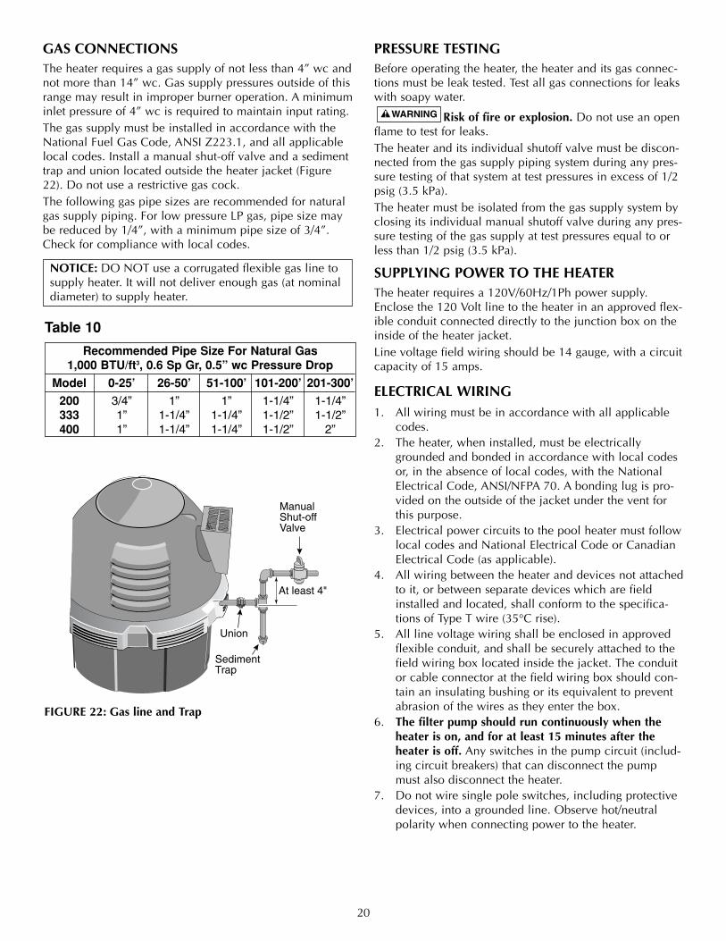
GAS CONNECTIONSThe heater requires a gas supply of not less than 4” wc andnot more than 14” wc. Gas supply pressures outside of thisrange may result in improper burner operation. A minimuminlet pressure of 4” wc is required to maintain input rating.The gas supply must be installed in accordance with theNational Fuel Gas Code, ANSI Z223.1, and all applicablelocal codes. Install a manual shut-off valve and a sedimenttrap and union located outside the heater jacket (Figure22). Do not use a restrictive gas cock. The following gas pipe sizes are recommended for naturalgas supply piping. For low pressure LP gas, pipe size maybe reduced by 1/4”, with a minimum pipe size of 3/4”.Check for compliance with local codes.
NOTICE: DO NOT use a corrugated flexible gas line tosupply heater. It will not deliver enough gas (at nominaldiameter) to supply heater.
PRESSURE TESTINGBefore operating the heater, the heater and its gas connec-tions must be leak tested. Test all gas connections for leakswith soapy water.
Risk of fire or explosion. Do not use an openflame to test for leaks.The heater and its individual shutoff valve must be discon-nected from the gas supply piping system during any pres-sure testing of that system at test pressures in excess of 1/2psig (3.5 kPa).The heater must be isolated from the gas supply system byclosing its individual manual shutoff valve during any pres-sure testing of the gas supply at test pressures equal to orless than 1/2 psig (3.5 kPa).
SUPPLYING POWER TO THE HEATERThe heater requires a 120V/60Hz/1Ph power supply.Enclose the 120 Volt line to the heater in an approved flex-ible conduit connected directly to the junction box on theinside of the heater jacket. Line voltage field wiring should be 14 gauge, with a circuitcapacity of 15 amps.
ELECTRICAL WIRING1. All wiring must be in accordance with all applicable
codes.2. The heater, when installed, must be electrically
grounded and bonded in accordance with local codesor, in the absence of local codes, with the NationalElectrical Code, ANSI/NFPA 70. A bonding lug is pro-vided on the outside of the jacket under the vent forthis purpose.
3. Electrical power circuits to the pool heater must followlocal codes and National Electrical Code or CanadianElectrical Code (as applicable).
4. All wiring between the heater and devices not attachedto it, or between separate devices which are fieldinstalled and located, shall conform to the specifica-tions of Type T wire (35°C rise).
5. All line voltage wiring shall be enclosed in approvedflexible conduit, and shall be securely attached to thefield wiring box located inside the jacket. The conduitor cable connector at the field wiring box should con-tain an insulating bushing or its equivalent to preventabrasion of the wires as they enter the box.
6. The filter pump should run continuously when theheater is on, and for at least 15 minutes after theheater is off. Any switches in the pump circuit (includ-ing circuit breakers) that can disconnect the pumpmust also disconnect the heater.
7. Do not wire single pole switches, including protectivedevices, into a grounded line. Observe hot/neutralpolarity when connecting power to the heater.
Manual Shut-offValve
Sediment Trap
Union
At least 4"
Recommended Pipe Size For Natural Gas1,000 BTU/ft3, 0.6 Sp Gr, 0.5” wc Pressure Drop
Model 0-25’ 26-50’ 51-100’ 101-200’ 201-300’
200 3/4” 1” 1” 1-1/4” 1-1/4”333 1” 1-1/4” 1-1/4” 1-1/2” 1-1/2”400 1” 1-1/4” 1-1/4” 1-1/2” 2”
FIGURE 22: Gas line and Trap
Table 10
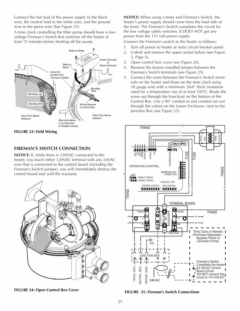
Connect the hot lead of the power supply to the blackwire, the neutral lead to the white wire, and the groundwire to the green wire (See Figure 23).A time clock controlling the filter pump should have a low-voltage Fireman’s Switch that switches off the heater atleast 15 minutes before shutting off the pump.
FIREMAN’S SWITCH CONNECTIONNOTICE: If, while there is 120VAC connected to theheater, you touch either 120VAC terminal with any 24VACwire that is connected to the control board (including theFireman’s Switch jumper), you will immediately destroy thecontrol board and void the warranty.
NOTICE: When using a timer and Fireman’s Switch, theheater’s power supply should come from the load side ofthe timer. The Fireman’s Switch completes the circuit forthe low voltage safety switches. It DOES NOT get anypower from the 115 volt power supply.Connect the Fireman’s switch to the heater as follows:1. Turn off power to heater at main circuit breaker panel.2. Unbolt and remove the upper jacket halves (see Figure
3, Page 5).3. Open control box cover (see Figure 24).4. Remove the factory-installed jumper between the
Fireman’s Switch terminals (see Figure 25).5. Connect the wires between the Fireman’s Switch termi-
nals on the heater and those on the time clock using18 gauge wire with a minimum 3/64” thick insulationrated for a temperature rise of at least 105°C. Route thewires out through the knockout on the bottom of theControl Box. Use a 90° conduit el and conduit run outthrough the cutout on the Lower Enclosure, next to theJunction Box (see Figure 23).
21
Wire into bottomof Junction-box in Flexible Conduit
Wiring Harnessto Control Box
Black to Black
White to White
Green (Ground)to
Green (Ground)
Bonding Wire
Bonding Wire
Bonding Lug
View From Below(Exterior)
View From Above(Interior)
Cutout for Conduit from Fireman's Switch
PRESS
TAB
VENT
PILOT
OF
FO
FF
ONO
N
GND
120V
AC (
HO
T)
GR
OU
ND
(G
ND
)
NEU
TRAL
(N
EU)
JUNCTION BOX
L1 L2
BM
FL
F1
TRANS TRANSFIREMANS
SWITCH
Fireman's SwitchCompletes the heater24 Volt AC Control Board Circuit.DO NOT connect thiscircuit to 115 Volt AC!
24V
AC
SE
C
PR
IM
120V
AC
Y Y
BK
BK
BK W
W
W
W
W
G
Y
Y
JMP3
VA
LT
HIN
DG
ND
24V
AC
24V
AC FS
TH
ER
MIS
TO
R
OPERATING CONTROL
DISABLE TOGGLEENABLE TOGGLE
1
CONTROL CENTER SPA CONTROL
VERSION 1 PAD
MEMBRANE PADCONNECTION
TERMINAL BOARD
TRAN
STRANS
TRAN
S
TRANS
FUSE
FUSE
NEUTRALTime Clock or Remote(Purchase Separately –
Supplies Power toCirculator Pump)
3663 0200
24VAC
FIGURE 24: Open Control Box Cover FIGURE 25: Fireman’s Switch Connections
FIGURE 23: Field Wiring
6. Reinstall and bolt up the jacket halves.The fuse for the Fireman’s Switch is 1.25 amp 1-1/4x1/4”fast blow fuse, available locally.
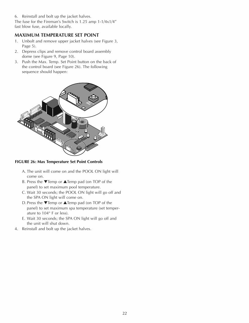
MAXIMUM TEMPERATURE SET POINT1. Unbolt and remove upper jacket halves (see Figure 3,
Page 5).2. Depress clips and remove control board assembly
dome (see Figure 9, Page 10).3. Push the Max. Temp. Set Point button on the back of
the control board (see Figure 26). The followingsequence should happen:
A. The unit will come on and the POOL ON light willcome on.
B. Press the ▼Temp or ▲Temp pad (on TOP of thepanel) to set maximum pool temperature.
C. Wait 30 seconds; the POOL ON light will go off andthe SPA ON light will come on.
D.Press the ▼Temp or ▲Temp pad (on TOP of thepanel) to set maximum spa temperature (set temper-ature to 104° F or less).
E. Wait 30 seconds; the SPA ON light will go off andthe unit will shut down.
4. Reinstall and bolt up the jacket halves.
22
S1SETMAX
S1
SETMAX
FIGURE 26: Max Temperature Set Point Controls
23
Start here for directions to specific Troubleshooting Chart
Hazardous voltage. Can shock, burn or kill. Disconnect power before servicing any components.
Fire and Explosion hazard. Do notjumper switch terminals to remedy a failed safetyswitch.
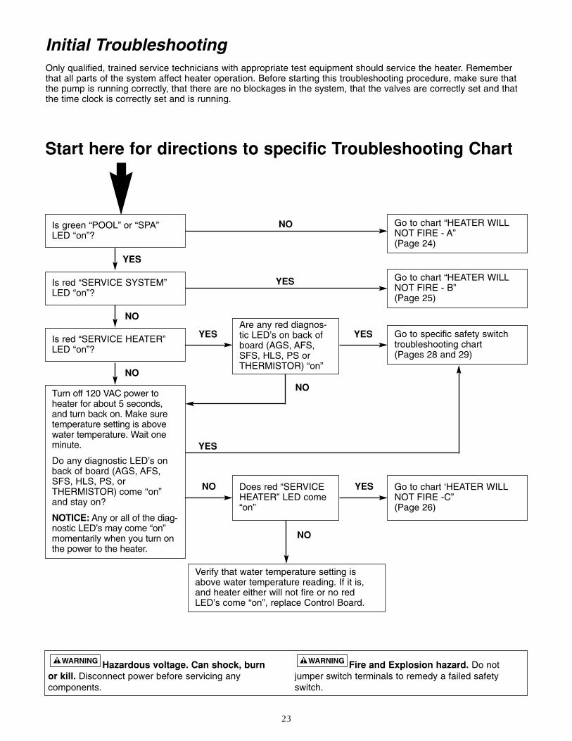
Initial TroubleshootingOnly qualified, trained service technicians with appropriate test equipment should service the heater. Rememberthat all parts of the system affect heater operation. Before starting this troubleshooting procedure, make sure thatthe pump is running correctly, that there are no blockages in the system, that the valves are correctly set and thatthe time clock is correctly set and is running.
Go to chart “HEATER WILLNOT FIRE - A”(Page 24)
Go to chart “HEATER WILLNOT FIRE - B” (Page 25)
Go to specific safety switchtroubleshooting chart (Pages 28 and 29)
Go to chart ‘HEATER WILLNOT FIRE -C” (Page 26)
Are any red diagnos-tic LED’s on back ofboard (AGS, AFS,SFS, HLS, PS orTHERMISTOR) “on”
NO
NO
NO
NO
NO
YES
YES
YES
NO
YES
YES
Does red “SERVICEHEATER” LED come“on”
Verify that water temperature setting isabove water temperature reading. If it is, and heater either will not fire or no red LED’s come “on”, replace Control Board.
YES
Is green “POOL” or “SPA”LED “on”?
Is red “SERVICE SYSTEM”LED “on”?
Is red “SERVICE HEATER”LED “on”?
Turn off 120 VAC power toheater for about 5 seconds,and turn back on. Make suretemperature setting is abovewater temperature. Wait oneminute.
Do any diagnostic LED’s onback of board (AGS, AFS,SFS, HLS, PS, or THERMISTOR) come “on”and stay on?
NOTICE: Any or all of the diag-nostic LED’s may come “on”momentarily when you turn onthe power to the heater.
24
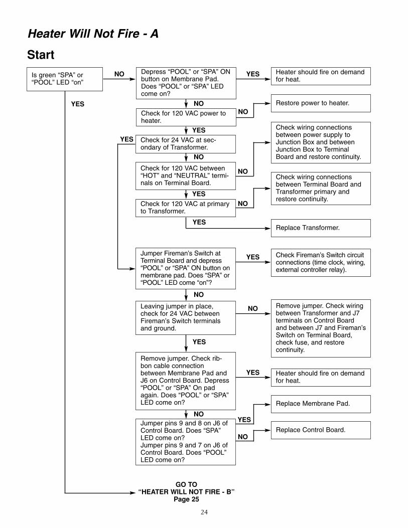
Heater Will Not Fire - A
Start
GO TO“HEATER WILL NOT FIRE - B”
Page 25
Heater should fire on demandfor heat.
Check Fireman’s Switch circuitconnections (time clock, wiring,external controller relay).
Remove jumper. Check wiringbetween Transformer and J7terminals on Control Boardand between J7 and Fireman’sSwitch on Terminal Board,check fuse, and restore continuity.
Restore power to heater.
Replace Transformer.
Heater should fire on demandfor heat.
Replace Control Board.
Replace Membrane Pad.
Check wiring connectionsbetween power supply toJunction Box and betweenJunction Box to TerminalBoard and restore continuity.
Check wiring connectionsbetween Terminal Board andTransformer primary andrestore continuity.
Is green “SPA” or“POOL” LED “on”
YES
NO YES
YES
YES
NO
NO
Depress “POOL” or “SPA” ONbutton on Membrane Pad.Does “POOL” or “SPA” LEDcome on?
Check for 120 VAC power toheater.
Check for 24 VAC at sec-ondary of Transformer.
Check for 120 VAC at primaryto Transformer.
Jumper Fireman’s Switch atTerminal Board and depress“POOL” or “SPA” ON button onmembrane pad. Does “SPA” or“POOL” LED come “on”?
Leaving jumper in place,check for 24 VAC betweenFireman’s Switch terminalsand ground.
Jumper pins 9 and 8 on J6 ofControl Board. Does “SPA”LED come on?Jumper pins 9 and 7 on J6 ofControl Board. Does “POOL”LED come on?
Remove jumper. Check rib-bon cable connectionbetween Membrane Pad andJ6 on Control Board. Depress“POOL” or “SPA” On padagain. Does “POOL” or “SPA”LED come on?
Check for 120 VAC between“HOT” and “NEUTRAL” termi-nals on Terminal Board.
NO
NO
NO
NO
YESYES
YES
YES
YES
NO
NO
YES
NO
25
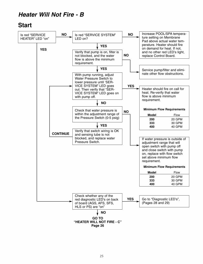
Heater Will Not Fire - B
StartIncrease POOL/SPA tempera-ture setting on MembranePad above actual water tem-perature. Heater should fireon demand for heat. If not,and no other red LED’s light,replace Control Board.
Service pump/filter and elimi-nate other flow obstructions.
Heater should fire on call forheat. Re-verify that water flow is above minimumrequirement.
Minimum Flow Requirements
Model Flow200 20 GPM333 30 GPM400 40 GPM
If water pressure is outside ofadjustment range that willopen switch with pump offand close switch with pumpon, replace with flow switchset above minimum flowrequirement.
Minimum Flow Requirements
Model Flow200 20 GPM333 30 GPM400 40 GPM
Is red “SERVICEHEATER” LED “on”
YES
YES
NO
YES
NO
NO
Is red “SERVICE SYSTEM”LED on?
Verify that pump is on, filter isnot blocked, and the waterflow is above the minimumrequirement.
Check that water pressure iswithin the adjustment range ofthe Pressure Switch (0-5 psig)
Verify that switch wiring is OKand sensing tube is notblocked, and replace waterPressure Switch.
Check whether any of thered diagnostic LED’s on backof board (AGS, AFS, SFS,HLS or PS) are “on”
GO TO“HEATER WILL NOT FIRE - C”
Page 26
Go to “Diagnostic LED’s”,(Pages 28 and 29)
With pump running, adjustWater Pressure Switch tolower pressure until ‘SER-VICE SYSTEM” LED goesout. Then verify that “SER-VICE SYSTEM” LED goes onwith pump off.
YES
YES
YES
NO
NO
NO
CONTINUE
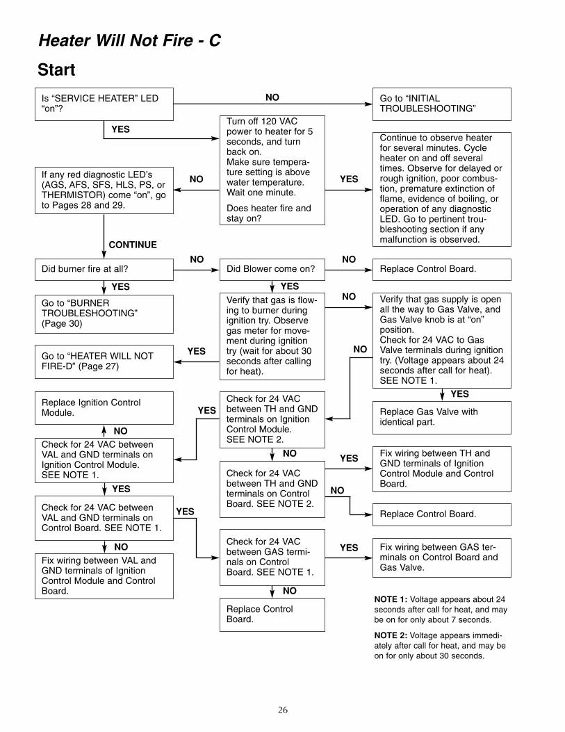
26
Heater Will Not Fire - C
Start
Go to “INITIALTROUBLESHOOTING”
Continue to observe heaterfor several minutes. Cycleheater on and off severaltimes. Observe for delayed orrough ignition, poor combus-tion, premature extinction offlame, evidence of boiling, oroperation of any diagnosticLED. Go to pertinent trou-bleshooting section if anymalfunction is observed.
Replace Control Board.
Replace Gas Valve with identical part.
Fix wiring between TH andGND terminals of IgnitionControl Module and ControlBoard.
Replace Control Board.
Fix wiring between GAS ter-minals on Control Board andGas Valve.
NOTE 1: Voltage appears about 24seconds after call for heat, and maybe on for only about 7 seconds.
NOTE 2: Voltage appears immedi-ately after call for heat, and may beon for only about 30 seconds.
Verify that gas supply is openall the way to Gas Valve, andGas Valve knob is at “on”position.Check for 24 VAC to GasValve terminals during ignitiontry. (Voltage appears about 24seconds after call for heat).SEE NOTE 1.
Turn off 120 VACpower to heater for 5seconds, and turnback on.Make sure tempera-ture setting is abovewater temperature.Wait one minute.
Does heater fire andstay on?
Did Blower come on?
Verify that gas is flow-ing to burner duringignition try. Observegas meter for move-ment during ignitiontry (wait for about 30seconds after callingfor heat).
Check for 24 VACbetween TH and GNDterminals on IgnitionControl Module. SEE NOTE 2.
Check for 24 VACbetween TH and GNDterminals on ControlBoard. SEE NOTE 2.
Check for 24 VACbetween GAS termi-nals on ControlBoard. SEE NOTE 1.
Replace ControlBoard.
NO
CONTINUE
YES
YES YES
NO
NO
YES
NO
YES
NO
NO
YES
YES
NO
YES
YES
Is “SERVICE HEATER” LED“on”?
Go to “BURNERTROUBLESHOOTING”(Page 30)
Go to “HEATER WILL NOTFIRE-D” (Page 27)
Check for 24 VAC betweenVAL and GND terminals onIgnition Control Module. SEE NOTE 1.
Check for 24 VAC betweenVAL and GND terminals onControl Board. SEE NOTE 1.
If any red diagnostic LED’s(AGS, AFS, SFS, HLS, PS, orTHERMISTOR) come “on”, goto Pages 28 and 29.
Did burner fire at all?
Replace Ignition ControlModule.
NO
YES
Fix wiring between VAL andGND terminals of IgnitionControl Module and ControlBoard.
NO
YES
NO
NO
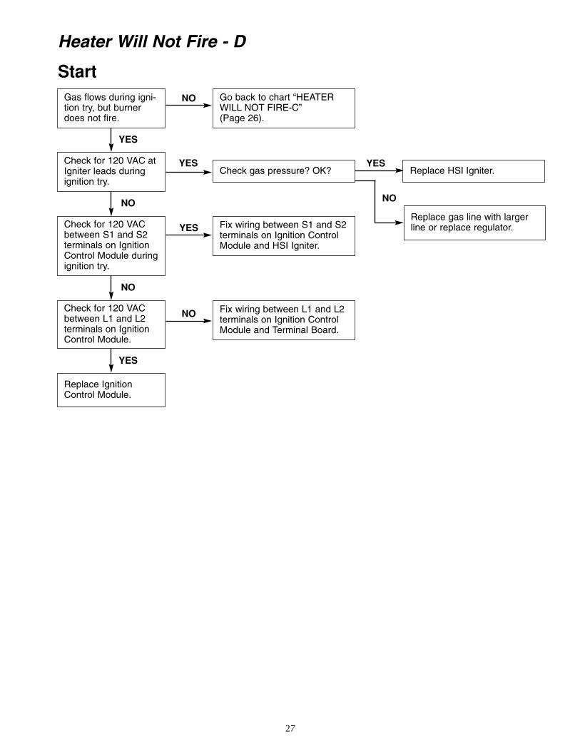
27
Heater Will Not Fire - D
StartGas flows during igni-tion try, but burnerdoes not fire.
Check for 120 VAC atIgniter leads duringignition try.
Check for 120 VACbetween S1 and S2terminals on IgnitionControl Module duringignition try.
Check for 120 VACbetween L1 and L2terminals on IgnitionControl Module.
Replace IgnitionControl Module.
YES
YES
NO NO
NO
NO
NO
YES
YESYES
Go back to chart “HEATERWILL NOT FIRE-C”(Page 26).
Check gas pressure? OK? Replace HSI Igniter.
Replace gas line with largerline or replace regulator.Fix wiring between S1 and S2
terminals on Ignition ControlModule and HSI Igniter.
Fix wiring between L1 and L2terminals on Ignition ControlModule and Terminal Board.
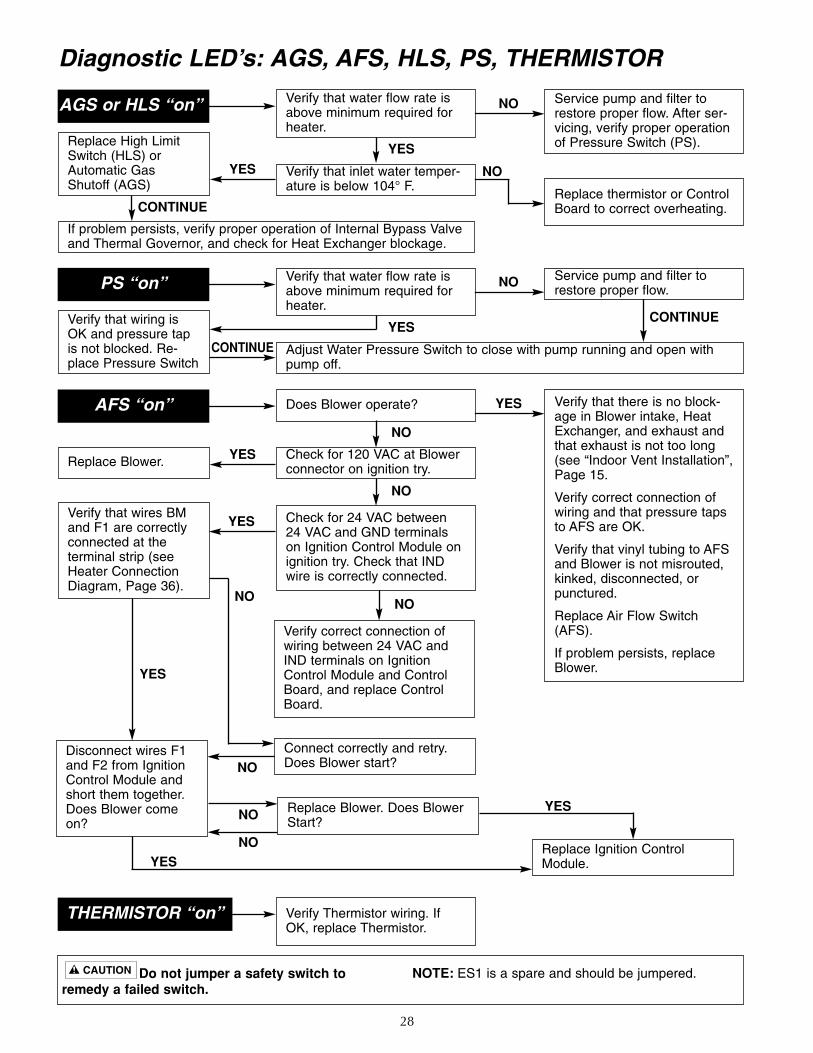
28
Diagnostic LED’s: AGS, AFS, HLS, PS, THERMISTOR
Do not jumper a safety switch to remedy a failed switch.
NOTE: ES1 is a spare and should be jumpered.
Service pump and filter torestore proper flow. After ser-vicing, verify proper operationof Pressure Switch (PS).
Replace thermistor or ControlBoard to correct overheating.
Replace High LimitSwitch (HLS) orAutomatic GasShutoff (AGS)
If problem persists, verify proper operation of Internal Bypass Valveand Thermal Governor, and check for Heat Exchanger blockage.
YES
NO
NO
AGS or HLS “on” Verify that water flow rate isabove minimum required forheater.
Verify that inlet water temper-ature is below 104° F.
YES
CONTINUE
YES
CONTINUE
Verify that there is no block-age in Blower intake, HeatExchanger, and exhaust andthat exhaust is not too long(see “Indoor Vent Installation”,Page 15.
Verify correct connection ofwiring and that pressure tapsto AFS are OK.
Verify that vinyl tubing to AFSand Blower is not misrouted,kinked, disconnected, orpunctured.
Replace Air Flow Switch(AFS).
If problem persists, replaceBlower.
Replace Blower.
Verify correct connection ofwiring between 24 VAC andIND terminals on IgnitionControl Module and ControlBoard, and replace ControlBoard.
YES
YES
NO
NO
NOYES
YES
YES
NO
AFS “on” Does Blower operate?
THERMISTOR “on” Verify Thermistor wiring. IfOK, replace Thermistor.
Check for 120 VAC at Blowerconnector on ignition try.
Connect correctly and retry.Does Blower start?
Replace Blower. Does BlowerStart?
Replace Ignition ControlModule.
NO
Verify that wires BMand F1 are correctlyconnected at the terminal strip (seeHeater ConnectionDiagram, Page 36).
Disconnect wires F1and F2 from IgnitionControl Module andshort them together.Does Blower comeon?
Check for 24 VAC between24 VAC and GND terminalson Ignition Control Module onignition try. Check that INDwire is correctly connected.
NO
NO
Service pump and filter torestore proper flow.
Verify that wiring isOK and pressure tapis not blocked. Re-place Pressure Switch
CONTINUE
NOPS “on” Verify that water flow rate isabove minimum required forheater.
Adjust Water Pressure Switch to close with pump running and open withpump off.
YES
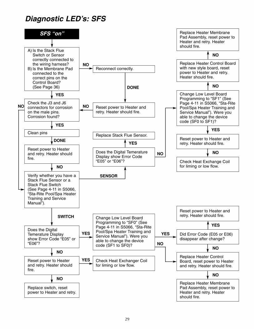
29
Diagnostic LED’s: SFS
Replace Heater MembranePad Assembly, reset power toHeater and retry. Heatershould fire.
Replace Heater MembranePad Assembly, reset power toHeater and retry. Heatershould fire.
Replace Heater Control Boardwith new style board, resetpower to Heater and retry.Heater should fire.
Change Low Level BoardProgramming to “SF1” (SeePage 4-11 in S5066, “Sta-RitePool/Spa Heater Training andService Manual”). Were youable to change the devicecode (SF0 to SF1)?
Reset power to Heater andretry. Heater should fire.
Check Heat Exchange Coilfor liming or low flow.
Reset power to Heater andretry. Heater should fire.
Did Error Code (E05 or E06)disappear after change?
Replace Heater ControlBoard, reset power to Heaterand retry. Heater should fire.
NO
YES
NO
NO
SENSOR
SWITCH
Reset power to Heater andretry. Heater should fire.
Does the Digital TemeratureDisplay show Error Code“E05” or “E06”?
Change Low Level BoardProgramming to “SF0” (SeePage 4-11 in S5066, “Sta-RitePool/Spa Heater Training andService Manual”). Were youable to change the devicecode (SF1 to SF0)?
Check Heat Exchanger Coilfor liming or low flow.
A) Is the Stack FlueSwitch or Sensor correctly connected tothe wiring harness?
B) Is the Membrane Padconnected to the correct pins on theControl Board? (See Page 36)
Check the J3 and J6 connectors for corrosionon the male pins.Corrosion found?
Clean pins
Reset power to Heaterand retry. Heater shouldfire.
Reset power to Heaterand retry. Heater shouldfire.
Replace switch, resetpower to Heater and retry.
Verify whether you have aStack Flue Sensor or aStack Flue Switch (See Page 4-11 in S5066,“Sta-Rite Pool/Spa HeaterTraining and ServiceManual”).
Does the DigitalTemerature Display show Error Code “E05” or“E06”?
NO
YES
YES
NO
SFS “on”
Reconnect correctly.
Replace Stack Flue Sensor.
DONE
YES
NO
NO
YES
YES
NO
NO
NO
YES
YESDONE
NO
NO
NO
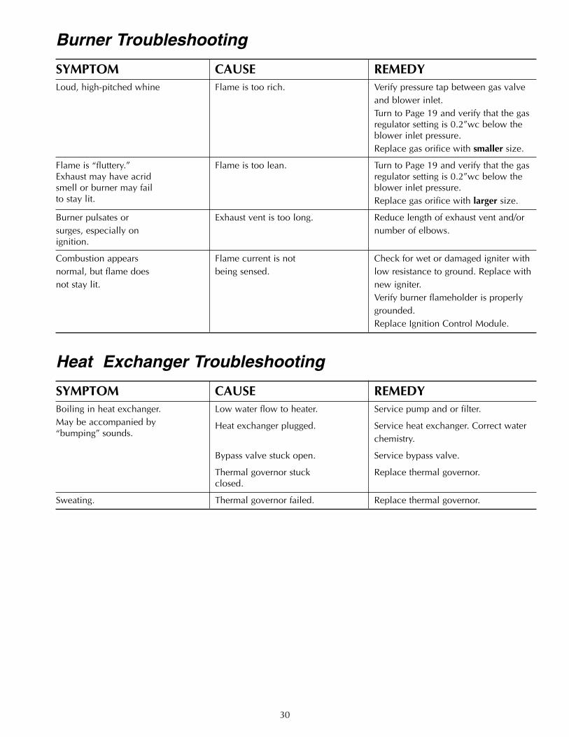
30
Burner Troubleshooting
SYMPTOM CAUSE REMEDYLoud, high-pitched whine Flame is too rich. Verify pressure tap between gas valve
and blower inlet.Turn to Page 19 and verify that the gasregulator setting is 0.2”wc below theblower inlet pressure.Replace gas orifice with smaller size.
Flame is “fluttery.” Flame is too lean. Turn to Page 19 and verify that the gasExhaust may have acrid regulator setting is 0.2”wc below thesmell or burner may fail blower inlet pressure.to stay lit. Replace gas orifice with larger size.
Burner pulsates or Exhaust vent is too long. Reduce length of exhaust vent and/orsurges, especially on number of elbows.ignition.
Combustion appears Flame current is not Check for wet or damaged igniter withnormal, but flame does being sensed. low resistance to ground. Replace withnot stay lit. new igniter.
Verify burner flameholder is properlygrounded.Replace Ignition Control Module.
Heat Exchanger Troubleshooting
SYMPTOM CAUSE REMEDYBoiling in heat exchanger. Low water flow to heater. Service pump and or filter.May be accompanied by Heat exchanger plugged. Service heat exchanger. Correct water“bumping” sounds.
chemistry.
Bypass valve stuck open. Service bypass valve.
Thermal governor stuck Replace thermal governor.closed.
Sweating. Thermal governor failed. Replace thermal governor.
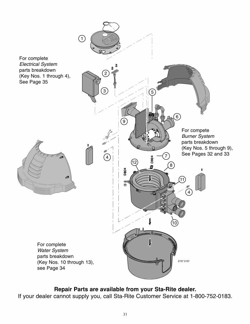
31
4
PRESS
TAB
VENT
PILOT
OFFOFF
ONON
2737 0197
1
3
4
5
6
7
8
10
9
2
12
11
For completeElectrical System parts breakdown(Key Nos. 1 through 4),See Page 34
For completeBurner Systemparts breakdown(Key Nos. 5 through 9),See Pages 31 and 32
For completeWater Systemparts breakdown(Key Nos. 10 through 12),See Page 33
Repair Parts are available from your Sta-Rite dealer.If your dealer cannot supply you, call Sta-Rite Customer Service at 1-800-752-0183.
For completeElectrical Systemparts breakdown(Key Nos. 1 through 4),See Page 35
For competeBurner Systemparts breakdown(Key Nos. 5 through 9),See Pages 32 and 33
For completeWater Systemparts breakdown(Key Nos. 10 through 13),see Page 34
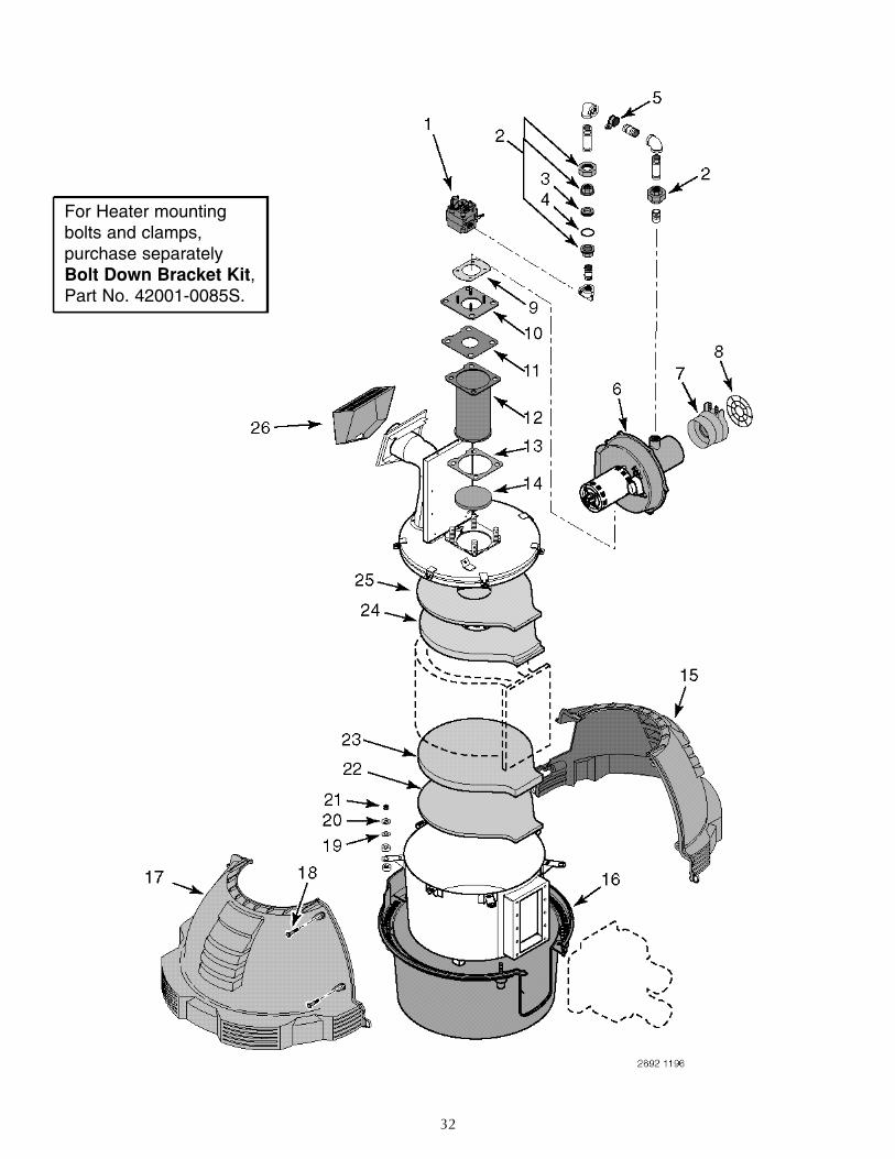
32
For Heater mountingbolts and clamps, purchase separatelyBolt Down Bracket Kit, Part No. 42001-0085S.
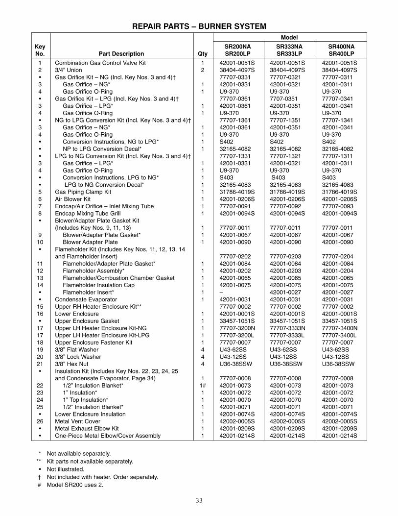
33
REPAIR PARTS – BURNER SYSTEMModel
Key SR200NA SR333NA SR400NANo. Part Description Qty SR200LP SR333LP SR400LP
1 Combination Gas Control Valve Kit 1 42001-0051S 42001-0051S 42001-0051S2 3/4” Union 2 38404-4097S 38404-4097S 38404-4097S• Gas Orifice Kit – NG (Incl. Key Nos. 3 and 4)† 77707-0331 77707-0321 77707-03113 Gas Orifice – NG* 1 42001-0331 42001-0321 42001-03114 Gas Orifice O-Ring 1 U9-370 U9-370 U9-370• Gas Orifice Kit – LPG (Incl. Key Nos. 3 and 4)† 77707-0361 7707-0351 77707-03413 Gas Orifice – LPG* 1 42001-0361 42001-0351 42001-03414 Gas Orifice O-Ring 1 U9-370 U9-370 U9-370• NG to LPG Conversion Kit (Incl. Key Nos. 3 and 4)† 77707-1361 77707-1351 77707-13413 Gas Orifice – NG* 1 42001-0361 42001-0351 42001-03414 Gas Orifice O-Ring 1 U9-370 U9-370 U9-370• Conversion Instructions, NG to LPG* 1 S402 S402 S402• NP to LPG Conversion Decal* 1 32165-4082 32165-4082 32165-4082• LPG to NG Conversion Kit (Incl. Key Nos. 3 and 4)† 77707-1331 77707-1321 77707-13113 Gas Orifice – LPG* 1 42001-0331 42001-0321 42001-03114 Gas Orifice O-Ring 1 U9-370 U9-370 U9-370• Conversion Instructions, LPG to NG* 1 S403 S403 S403• LPG to NG Conversion Decal* 1 32165-4083 32165-4083 32165-40835 Gas Piping Clamp Kit 1 31786-4019S 31786-4019S 31786-4019S6 Air Blower Kit 1 42001-0206S 42001-0206S 42001-0206S7 Endcap/Air Orifice – Inlet Mixing Tube 1 77707-0091 77707-0092 77707-00938 Endcap Mixing Tube Grill 1 42001-0094S 42001-0094S 42001-0094S• Blower/Adapter Plate Gasket Kit
(Includes Key Nos. 9, 11, 13) 1 77707-0011 77707-0011 77707-00119 Blower/Adapter Plate Gasket* 1 42001-0067 42001-0067 42001-006710 Blower Adapter Plate 1 42001-0090 42001-0090 42001-0090• Flameholder Kit (Includes Key Nos. 11, 12, 13, 14
and Flameholder Insert) 77707-0202 77707-0203 77707-020411 Flameholder/Adapter Plate Gasket* 1 42001-0084 42001-0084 42001-008412 Flameholder Assembly* 1 42001-0202 42001-0203 42001-020413 Flameholder/Combustion Chamber Gasket 1 42001-0065 42001-0065 42001-006514 Flameholder Insulation Cap 1 42001-0075 42001-0075 42001-0075• Flameholder Insert* 1 – 42001-0027 42001-0027• Condensate Evaporator 1 42001-0031 42001-0031 42001-0031
15 Upper RH Heater Enclosure Kit** 77707-0002 77707-0002 77707-000216 Lower Enclosure 1 42001-0001S 42001-0001S 42001-0001S• Upper Enclosure Gasket 1 33457-1051S 33457-1051S 33457-1051S
17 Upper LH Heater Enclosure Kit-NG 1 77707-3200N 77707-3333N 77707-3400N17 Upper LH Heater Enclosure Kit-LPG 1 77707-3200L 77707-3333L 77707-3400L18 Upper Enclosure Fastener Kit 1 77707-0007 77707-0007 77707-000719 3/8” Flat Washer 4 U43-62SS U43-62SS U43-62SS20 3/8” Lock Washer 4 U43-12SS U43-12SS U43-12SS21 3/8” Hex Nut 4 U36-38SSW U36-38SSW U36-38SSW• Insulation Kit (Includes Key Nos. 22, 23, 24, 25
and Condensate Evaporator, Page 34) 1 77707-0008 77707-0008 77707-000822 1/2” Insulation Blanket* 1# 42001-0073 42001-0073 42001-007323 1” Insulation* 1 42001-0072 42001-0072 42001-007224 1” Top Insulation* 1 42001-0070 42001-0070 42001-007025 1/2” Insulation Blanket* 1 42001-0071 42001-0071 42001-0071• Lower Enclosure Insulation 1 42001-0074S 42001-0074S 42001-0074S
26 Metal Vent Cover 1 42002-0005S 42002-0005S 42002-0005S• Metal Exhaust Elbow Kit 1 42001-0209S 42001-0209S 42001-0209S• One-Piece Metal Elbow/Cover Assembly 1 42001-0214S 42001-0214S 42001-0214S
* Not available separately.** Kit parts not available separately.• Not illustrated.† Not included with heater. Order separately.# Model SR200 uses 2.
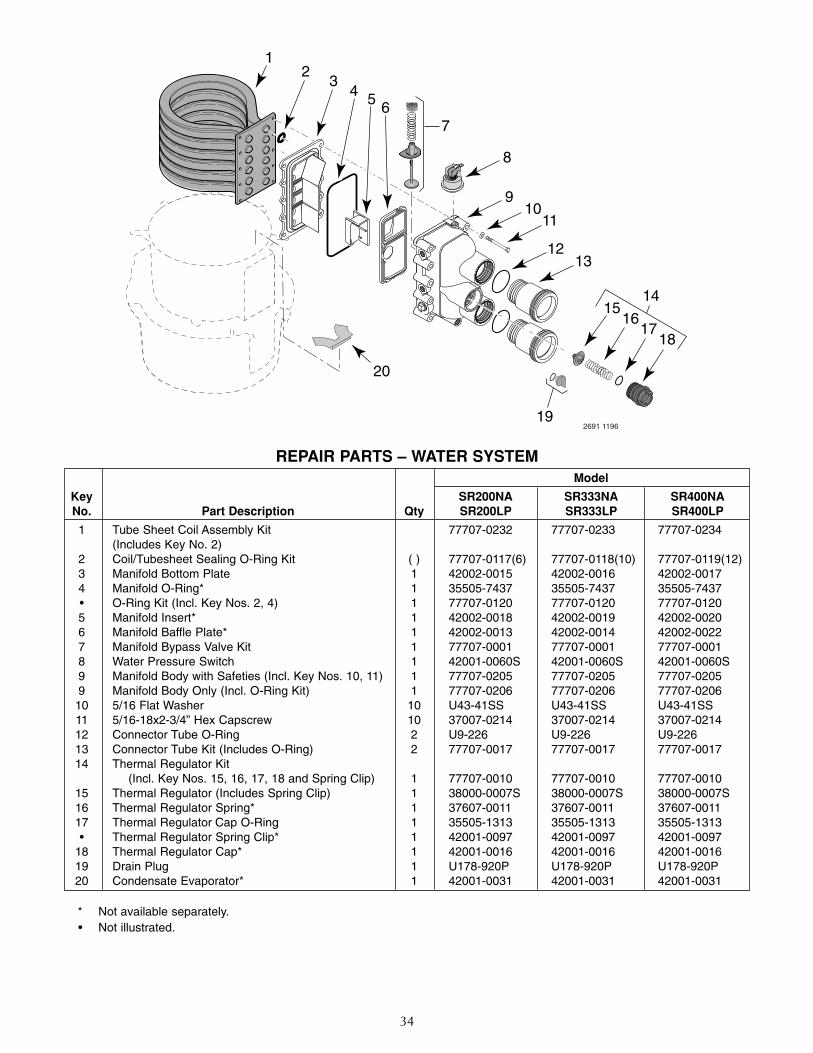
34
REPAIR PARTS – WATER SYSTEM
12
19
20
34
7
8
1110
9
65
2691 1196
18
13
14
12
1716
15
* Not available separately.• Not illustrated.
Model
Key SR200NA SR333NA SR400NANo. Part Description Qty SR200LP SR333LP SR400LP
1 Tube Sheet Coil Assembly Kit 77707-0232 77707-0233 77707-0234(Includes Key No. 2)
2 Coil/Tubesheet Sealing O-Ring Kit ( ) 77707-0117(6) 77707-0118(10) 77707-0119(12)3 Manifold Bottom Plate 1 42002-0015 42002-0016 42002-00174 Manifold O-Ring* 1 35505-7437 35505-7437 35505-7437• O-Ring Kit (Incl. Key Nos. 2, 4) 1 77707-0120 77707-0120 77707-01205 Manifold Insert* 1 42002-0018 42002-0019 42002-00206 Manifold Baffle Plate* 1 42002-0013 42002-0014 42002-00227 Manifold Bypass Valve Kit 1 77707-0001 77707-0001 77707-00018 Water Pressure Switch 1 42001-0060S 42001-0060S 42001-0060S9 Manifold Body with Safeties (Incl. Key Nos. 10, 11) 1 77707-0205 77707-0205 77707-02059 Manifold Body Only (Incl. O-Ring Kit) 1 77707-0206 77707-0206 77707-0206
10 5/16 Flat Washer 10 U43-41SS U43-41SS U43-41SS11 5/16-18x2-3/4” Hex Capscrew 10 37007-0214 37007-0214 37007-021412 Connector Tube O-Ring 2 U9-226 U9-226 U9-22613 Connector Tube Kit (Includes O-Ring) 2 77707-0017 77707-0017 77707-001714 Thermal Regulator Kit
(Incl. Key Nos. 15, 16, 17, 18 and Spring Clip) 1 77707-0010 77707-0010 77707-001015 Thermal Regulator (Includes Spring Clip) 1 38000-0007S 38000-0007S 38000-0007S16 Thermal Regulator Spring* 1 37607-0011 37607-0011 37607-001117 Thermal Regulator Cap O-Ring 1 35505-1313 35505-1313 35505-1313• Thermal Regulator Spring Clip* 1 42001-0097 42001-0097 42001-0097
18 Thermal Regulator Cap* 1 42001-0016 42001-0016 42001-001619 Drain Plug 1 U178-920P U178-920P U178-920P20 Condensate Evaporator* 1 42001-0031 42001-0031 42001-0031
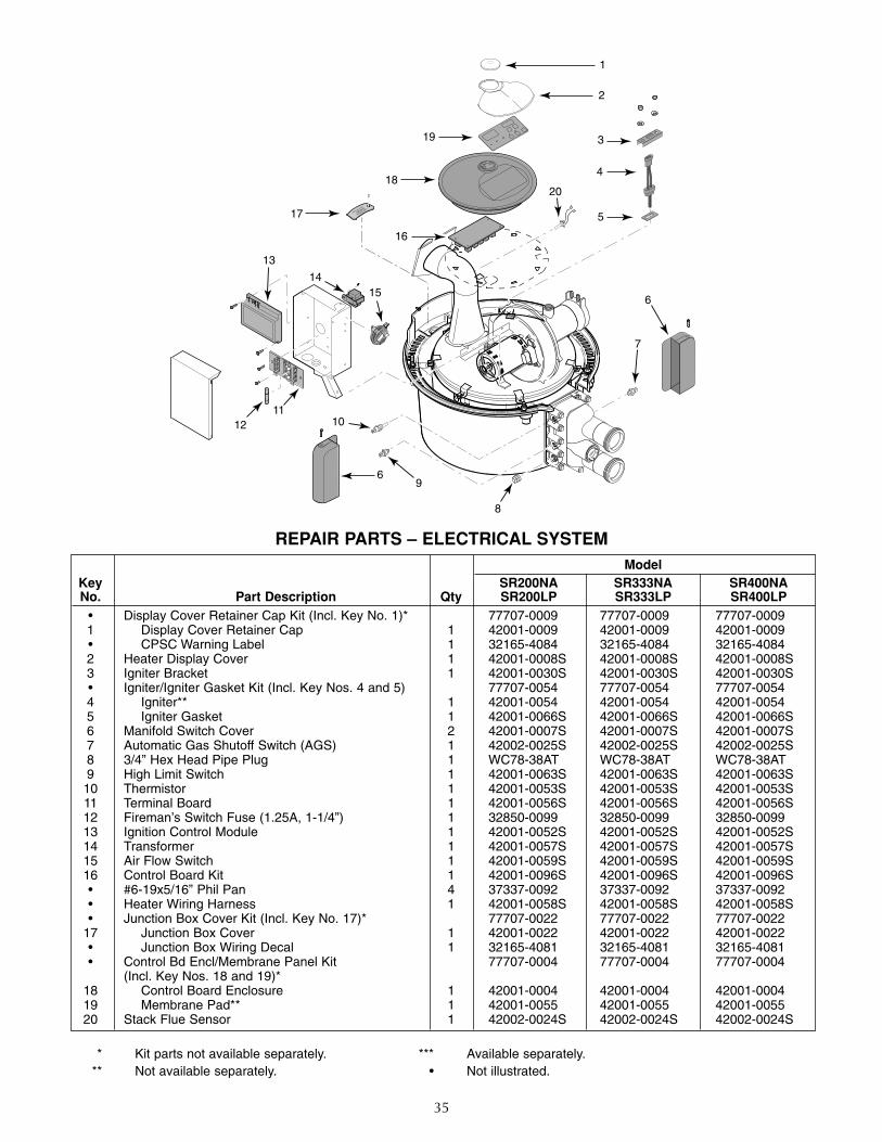
35
REPAIR PARTS – ELECTRICAL SYSTEM
1
2
3
9
6
8
6
1011
12
13
4
5
20
14
17
19
18
15
16
7
ModelKey SR200NA SR333NA SR400NANo. Part Description Qty SR200LP SR333LP SR400LP
• Display Cover Retainer Cap Kit (Incl. Key No. 1)* 77707-0009 77707-0009 77707-00091 Display Cover Retainer Cap 1 42001-0009 42001-0009 42001-0009• CPSC Warning Label 1 32165-4084 32165-4084 32165-40842 Heater Display Cover 1 42001-0008S 42001-0008S 42001-0008S3 Igniter Bracket 1 42001-0030S 42001-0030S 42001-0030S• Igniter/Igniter Gasket Kit (Incl. Key Nos. 4 and 5) 77707-0054 77707-0054 77707-00544 Igniter** 1 42001-0054 42001-0054 42001-00545 Igniter Gasket 1 42001-0066S 42001-0066S 42001-0066S6 Manifold Switch Cover 2 42001-0007S 42001-0007S 42001-0007S7 Automatic Gas Shutoff Switch (AGS) 1 42002-0025S 42002-0025S 42002-0025S8 3/4” Hex Head Pipe Plug 1 WC78-38AT WC78-38AT WC78-38AT9 High Limit Switch 1 42001-0063S 42001-0063S 42001-0063S
10 Thermistor 1 42001-0053S 42001-0053S 42001-0053S11 Terminal Board 1 42001-0056S 42001-0056S 42001-0056S12 Fireman’s Switch Fuse (1.25A, 1-1/4”) 1 32850-0099 32850-0099 32850-009913 Ignition Control Module 1 42001-0052S 42001-0052S 42001-0052S14 Transformer 1 42001-0057S 42001-0057S 42001-0057S15 Air Flow Switch 1 42001-0059S 42001-0059S 42001-0059S16 Control Board Kit 1 42001-0096S 42001-0096S 42001-0096S• #6-19x5/16” Phil Pan 4 37337-0092 37337-0092 37337-0092• Heater Wiring Harness 1 42001-0058S 42001-0058S 42001-0058S• Junction Box Cover Kit (Incl. Key No. 17)* 77707-0022 77707-0022 77707-0022
17 Junction Box Cover 1 42001-0022 42001-0022 42001-0022• Junction Box Wiring Decal 1 32165-4081 32165-4081 32165-4081• Control Bd Encl/Membrane Panel Kit 77707-0004 77707-0004 77707-0004
(Incl. Key Nos. 18 and 19)*18 Control Board Enclosure 1 42001-0004 42001-0004 42001-000419 Membrane Pad** 1 42001-0055 42001-0055 42001-005520 Stack Flue Sensor 1 42002-0024S 42002-0024S 42002-0024S
* Kit parts not available separately.** Not available separately.
*** Available separately.• Not illustrated.
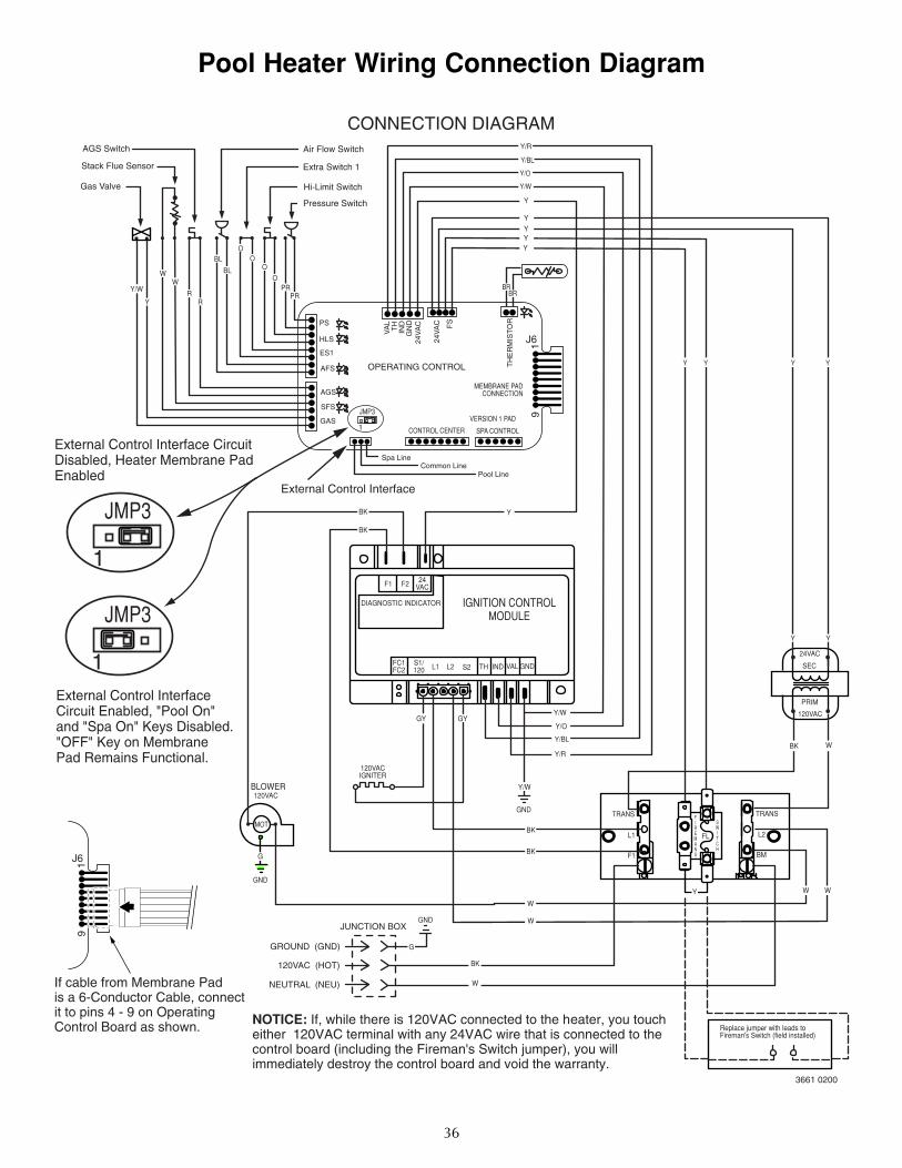
36
Pool Heater Wiring Connection Diagram
JMP3 91
J6
JMP3
1
JMP3
1
External Control Interface Circuit Disabled, Heater Membrane Pad Enabled
External Control Interface Circuit Enabled, "Pool On"and "Spa On" Keys Disabled. "OFF" Key on Membrane Pad Remains Functional.
CONNECTION DIAGRAMAGS Switch
Stack Flue Sensor
Gas Valve
Air Flow Switch
Extra Switch 1
Hi-Limit Switch
Pressure Switch
VA
LT
HIN
DG
ND
24V
AC
24V
AC FS
TH
ER
MIS
TO
R
OPERATING CONTROL
1
PS
HLS
ES1
AFS
AGS
SFS
GASCONTROL CENTER SPA CONTROL
VERSION 1 PAD
MEMBRANE PADCONNECTION
Spa LineCommon Line
Pool Line
IGNITION CONTROLMODULE
DIAGNOSTIC INDICATOR
F1 F2 24VAC
FC1FC2
S1/120 L1
L1 L2
BM
FL
F1
L2 S2 TH IND VAL GND
GND
GND
GND
BLOWER120VAC
120VAC (HOT)
120VACIGNITER
MOTTRANS TRANS
GROUND (GND)
NEUTRAL (NEU)
JUNCTION BOX
FIREMANS
SWITCH
Replace jumper with leads to Fireman's Switch (field installed)
24VAC
SEC
PRIM
120VACY/W
Y/W
Y/R
Y/O
Y/BLBK
GY GY
BK
BK
W
W
BK
W
W
W W
G
G
Y
Y
YY
BK
BK
Y/W
WW
RR
BL
BL
OO
O
OPR
PR
Y/R
Y/BL
Y/O
Y/W
Y
Y
YYY
Y Y Y Y
BRBR
3661 0200
External Control Interface
If cable from Membrane Pad is a 6-Conductor Cable, connectit to pins 4 - 9 on Operating Control Board as shown.
Y
91
J6
NOTICE: If, while there is 120VAC connected to the heater, you touch either 120VAC terminal with any 24VAC wire that is connected to the control board (including the Fireman's Switch jumper), you willimmediately destroy the control board and void the warranty.
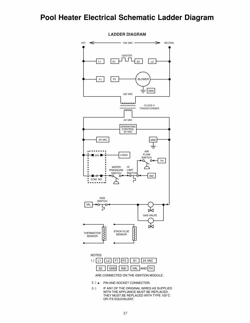
37
Pool Heater Electrical Schematic Ladder Diagram
HOT NEUTRAL120 VAC
120 VAC
IGNITER
L1 S1 S2 L2
F1 F2 BLOWER
GND
GND
CLASS IITRANSFORMER
24 VAC
24 VAC
24V
OPERATINGCONTROL
24 VAC
LOGIC
TH
IND
AIRFLOW
SWITCH
HILIMITSWITCH
WATERPRESSURE
SWITCH
COM NO
AGSSWITCH
VAL
GAS VALVE
THERMISTORSENSOR
STACK FLUESENSOR
NOTES:
1.)
AND TH
L1 L2 F1 F2 S1 24 VAC
S2 GND IND VAL
ARE CONNECTED ON THE IGNITION MODULE.
2. )
3. )
PIN AND SOCKET CONNECTOR.
IF ANY OF THE ORIGINAL WIRES AS SUPPLIED WITH THE APPLIANCE MUST BE REPLACED, THEY MUST BE REPLACED WITH TYPE 105°COR ITS EQUIVALENT.
LADDER DIAGRAM

38

39
▲ Retain Warranty Certificate (upper portion) in a safe and convenient location for your records.
DETACH HERE: Fill out bottom portion completely and mail within 10 days of purchase/installation to:▼ Sta-Rite, Attn: Warranty Dept., 293 Wright St., Delavan, WI 53115
Pumps, filters, skimmers, underwater lights (except bulbs),accessories and fittings manufactured by Sta-Rite are war-ranted to be free of defects in material and workmanshipfor one (1) year from date of installation.
Product specific warranties: Year from date of installation
HRPB, DEPB, System 3, and PL – Tanks . . . . . . .10 yearsInternal filter components and valves . . . . . . . . 1 year
Max-E-Therm – Pool/Spa Heaters . . . . . . . . . . . . 2 yearsHeater Enclosure only (Upper RH & LH;lower enclosure; and control board enclosure)…10 years
Automatic Pool Cleaners including Hose . . . . . . 2 years
Cristal-Flo filters – Tanks . . . . . . . . . . .10 years pro-rated* Valve and internal components. . . . . . . . . . . . . . 1 year
Posi-Flo II – Tanks . . . . . . . . . . . . . . . . . . . . . . . .10 years Elements . . . . . . . . . . . . . . . . . . . . . . . . . . . . . . 1 year
PRC Cartridge – Filter Tanks . . . . . . . . .5 years pro-rated (1st 2 years full) Elements . . . . . . . . . . . . . . . . . . . . . . . . . . . . . . 1 year
System 3 Above Ground Systems – Tanks . . . . . .10 years Pumps / Platform and Internals . . . . . . . . . . . . . 1 year
Pumps . . . . . . . . . . . . . . . . . . . . . . . . . . . . . . . . . . 1 yearWhen equipped with A.O. Smith 2-compartment motors (Does not includepumps sold as part of a systems package) . . . . . 2 years
Traps / In-Line Strainers . . . . . . . . . . . . . . . . . . . 1 year
Vertical Commercial Filter – Tanks . . . . . . . . . . .10 years Internals . . . . . . . . . . . . . . . . . . . . . . . . . . . . . . . 1 year
Horizontal Commercial FilterTanks . . . . . . . . . . . . . . . . . . . . . . . . . . . . . . . . .5 years(Years 6-9, Prorated declining 20%/year,Yr. 10 - 10%)Internals . . . . . . . . . . . . . . . . . . . . . . . . . . . . . . . 1 year
* Full warranty coverage is in effect for one year after instal-lation.The pro-rated warranty covers the tank only duringthe 2nd through 10th year after installation.The amount cov-ered decreases by 10% each year. (ie., 2nd year 90% covered,3rd year 80% covered, etc.).
The foregoing warranties relate to the original consumerpurchaser (“Purchaser”) only. Sta-Rite shall have the optionto repair or replace the defective product, at its sole discre-tion. Purchasers must pay all labor and shipping chargesnecessary to replace the product covered by this warranty.Requests for warranty service must be made through theinstalling dealer.This warranty shall not apply to any prod-uct that has been subject to negligence, misapplication,improper installation or maintenance, or other circum-stances which are not in Sta-Rite’s direct control.
This warranty sets forth Sta-Rite’s sole obligation andPurchaser’s exclusive remedy for defective products.
STA-RITE SHALL NOT BE LIABLE FOR ANY CONSEQUENTIAL,INCIDENTAL OR CONTINGENT DAMAGES WHATSOEVER.
THE FOREGOING WARRANTIES ARE EXCLUSIVE AND INLIEU OF ALL OTHER EXPRESS WARRANTIES. IMPLIED WAR-RANTIES, INCLUDING BUT NOT LIMITED TO THE IMPLIEDWARRANTIES OF MERCHANTABILITY AND FITNESS FOR APARTICULAR PURPOSE, SHALL NOT EXTEND BEYOND THEDURATION OF THE APPLICABLE EXPRESS WARRANTIESPROVIDED HEREIN.
Some states do not allow the exclusion or limitation of inci-dental or consequential damages or limitations on how longan implied warranty lasts, so the above limitations or exclu-sion may not apply to you.This warranty gives you specificlegal rights and you may also have other rights which varyfrom state to state.
Supersedes all previous publications.
Sta-Rite Industries 293 Wright St., Delavan, WI 53115
Warranty Registration Card
Name
Address
City State Zip
Purchase Date
Product Purchased
■■ New installation ■■ Replacement
Type of Pool ■■ Inground ■■ Vinyl ■■ Fiberglass ■■ Gunite
Size of Pool
Years pool has been in service ■■ less than 1 ■■ 1-3 ■■ 3-5 ■■ 5-10
Purchased from: Company name
Address
City State Zip
Please send me more information on these other products from Sta-Rite.
■■ Pumps ■■ Filters ■■ Automatic Pool Cleaners
■■ Maintenance Equipment ■■ Test Strips
■■ Heaters
S4877PS (Rev. 1/22/01)
STA-RITE LIMITED WARRANTY