Embed Size (px)
Citation preview
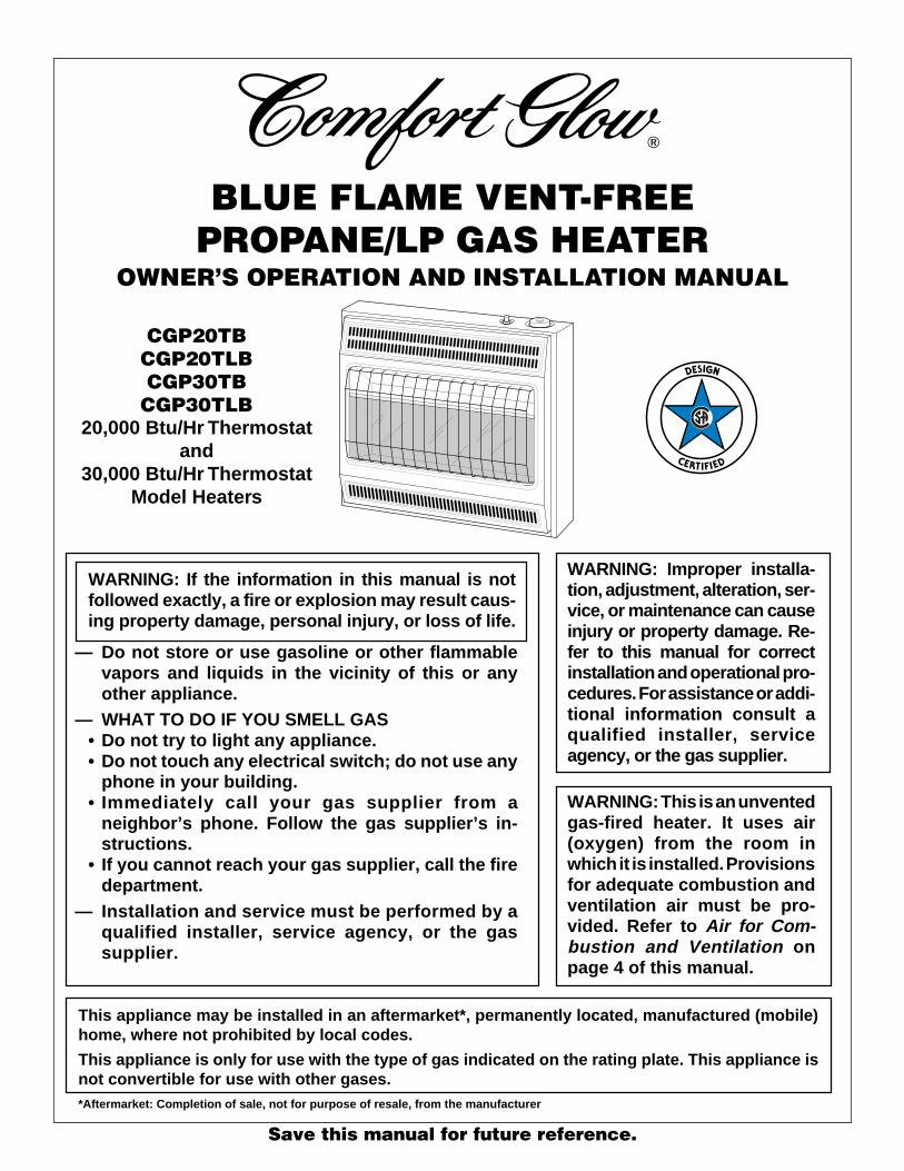
BLUE FLAME VENT-FREEPROPANE/LP GAS HEATER
OWNER’S OPERATION AND INSTALLATION MANUAL
WARNING: If the information in this manual is notfollowed exactly, a fire or explosion may result caus-ing property damage, personal injury, or loss of life.
— Do not store or use gasoline or other flammablevapors and liquids in the vicinity of this or anyother appliance.
— WHAT TO DO IF YOU SMELL GAS• Do not try to light any appliance.• Do not touch any electrical switch; do not use any
phone in your building.• Immediately call your gas supplier from a
neighbor’s phone. Follow the gas supplier’s in-structions.
• If you cannot reach your gas supplier, call the firedepartment.
— Installation and service must be performed by aqualified installer, service agency, or the gassupplier.
Save this manual for future reference.
CGP20TBCGP20TLBCGP30TB
CGP30TLB20,000 Btu/Hr Thermostat
and30,000 Btu/Hr Thermostat
Model Heaters
WARNING: Improper installa-tion, adjustment, alteration, ser-vice, or maintenance can causeinjury or property damage. Re-fer to this manual for correctinstallation and operational pro-cedures. For assistance or addi-tional information consult aqualified installer, serviceagency, or the gas supplier.
WARNING: This is an unventedgas-fired heater. It uses air(oxygen) from the room inwhich it is installed. Provisionsfor adequate combustion andventilation air must be pro-vided. Refer to Air for Com-bustion and Ventilation onpage 4 of this manual.
This appliance may be installed in an aftermarket*, permanently located, manufactured (mobile)home, where not prohibited by local codes.
This appliance is only for use with the type of gas indicated on the rating plate. This appliance isnot convertible for use with other gases.*Aftermarket: Completion of sale, not for purpose of resale, from the manufacturer
2 104332
BLUE FLAME PROPANE/LP HEATER
SAFETYINFORMATION
Carbon Monoxide Poisoning: Early signsof carbon monoxide poisoning resemble theflu, with headaches, dizziness, or nausea. Ifyou have these signs, the heater may not beworking properly. Get fresh air at once!Have heater serviced. Some people aremore affected by carbon monoxide thanothers. These include pregnant women,people with heart or lung disease or anemia,those under the influence of alcohol, andthose at high altitudes.
Propane/LP Gas: Propane/LP gas is odor-less. An odor-making agent is added to pro-pane/LP gas. The odor helps you detect apropane/LP gas leak. However, the odor addedto propane/LP gas can fade. Propane/LP gasmay be present even though no odor exists.
Make certain you read and understand allwarnings. Keep this manual for reference. Itis your guide to safe and proper operation ofthis heater.
WARNINGS
IMPORTANT: Read this owner’smanual carefully and completelybefore trying to assemble, oper-ate, or service this heater. Im-proper use of this heater cancause serious injury or death fromburns, fire, explosion, electricalshock, and carbon monoxidepoisoning.
DANGER: Carbon monoxidepoisoning may lead to death!
1. This appliance is only for use with thetype of gas indicated on the rating plate.This appliance is not convertible for usewith other gases.
2. Do not place propane/LP supply tank(s)inside any structure. Locate propane/LP supply tank(s) outdoors.
3. If you smell gas• shut off gas supply• do not try to light any appliance• do not touch any electrical switch; do
not use any phone in your building• immediately call your gas supplier
from a neighbor’s phone. Follow thegas supplier’s instructions
• if you cannot reach your gas supplier,call the fire department
WARNING: Any change tothis heater or its controls can bedangerous.
4. This heater shall not be installed in abedroom or bathroom.
5. This heater needs fresh, outside air ven-tilation to run properly. This heater hasan Oxygen Depletion Sensing (ODS)safety shutoff system. The ODS shutsdown the heater if not enough fresh airis available. See Air for Combustionand Ventilation, pages 4 through 6.
6. Keep air openings in front and bottomof heater clear and free of debris. Thiswill ensure enough air for proper com-bustion.
7. If heater shuts off, do not relight untilyou provide fresh, outside air. If heaterkeeps shutting off, have it serviced.
8. Do not run heater• where flammable liquids or vapors
are used or stored• under dusty conditions
9. Do not use heater if any part has beenunder water. Immediately call a quali-fied service technician to inspect theroom heater and to replace any part ofthe control system and any gas controlwhich has been under water.
10. Turn off and unplug heater and let coolbefore servicing. Only a qualified ser-vice person should service and repairheater.
11. Operating heater above elevations of4,500 feet could cause pilot outage.
12. To prevent performance problems, donot use propane/LP fuel tank of lessthan 100 lbs. capacity.
Do not place clothing or otherflammable material on or nearthe appliance. Never place anyobjects on the heater.
Surface of heater becomes veryhot when running heater. Keepchildren and adults away fromhot surface to avoid burns orclothing ignition. Heater will re-main hot for a time after shut-down. Allow surface to cool be-fore touching.
Carefully supervise young chil-dren when they are in the sameroom with heater.
Make sure grill guard is in placebefore running heater.
Keep the appliance area clear andfree from combustible materials,gasoline and other flammablevapors and liquids.
Due to high temperatures, theappliance should be located outof traffic and away from furnitureand draperies.
WARNING: Do not use anyaccessory not approved for usewith this heater.
3104332
OWNER’S MANUAL
PRODUCTIDENTIFICATION
LOCAL CODESInstall and use heater with care. Follow all localcodes. In the absence of local codes, use thelatest edition of The National Fuel Gas CodeANS Z223.1, also known as NFPA 54*.
*Available from:
American National Standards Institute, Inc.1430 Broadway
New York, NY 10018
National Fire Protection Association, Inc.Batterymarch ParkQuincy, MA 02269
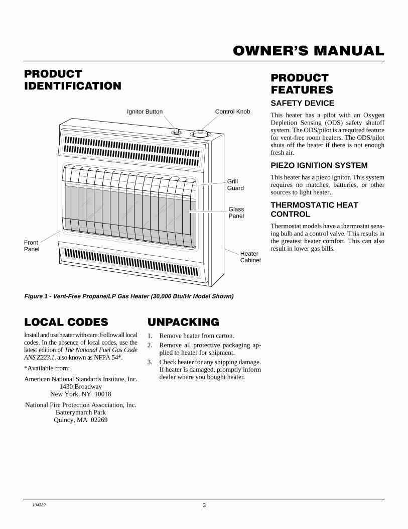
Figure 1 - Vent-Free Propane/LP Gas Heater (30,000 Btu/Hr Model Shown)
UNPACKING1. Remove heater from carton.
2. Remove all protective packaging ap-plied to heater for shipment.
3. Check heater for any shipping damage.If heater is damaged, promptly informdealer where you bought heater.
PRODUCTFEATURESSAFETY DEVICEThis heater has a pilot with an OxygenDepletion Sensing (ODS) safety shutoffsystem. The ODS/pilot is a required featurefor vent-free room heaters. The ODS/pilotshuts off the heater if there is not enoughfresh air.
PIEZO IGNITION SYSTEMThis heater has a piezo ignitor. This systemrequires no matches, batteries, or othersources to light heater.
THERMOSTATIC HEATCONTROLThermostat models have a thermostat sens-ing bulb and a control valve. This results inthe greatest heater comfort. This can alsoresult in lower gas bills.
Ignitor Button Control Knob
HeaterCabinet
FrontPanel
GlassPanel
GrillGuard
4 104332
BLUE FLAME PROPANE/LP HEATER
AIR FORCOMBUSTION ANDVENTILATION
Today’s homes are built more energy effi-cient than ever. New materials, increasedinsulation, and new construction methodshelp reduce heat loss in homes. Home ownersweather strip and caulk around windows anddoors to keep the cold air out and the warm airin. During heating months, home ownerswant their homes as airtight as possible.
While it is good to make your home energyefficient, your home needs to breathe. Freshair must enter your home. All fuel-burningappliances need fresh air for proper com-bustion and ventilation.
Exhaust fans, fireplaces, clothes dryers, andfuel burning appliances draw air from thehouse to operate. You must provide ad-equate fresh air for these appliances. Thiswill insure proper venting of vented fuel-burning appliances.
Confined and Unconfined Space
The National Fuel Gas Code ANS Z223.1defines a confined space as a space whosevolume is less than 50 cubic feet per 1,000Btu per hour (4.8 m3 per kw) of the aggre-gate input rating of all appliances installedin that space and an unconfined space as aspace whose volume is not less than 50cubic feet per 1,000 Btu per hour (4.8 m3 perkw) of the aggregate input rating of allappliances installed in that space. Roomscommunicating directly with the space inwhich the appliances are installed*, throughopenings not furnished with doors, are con-sidered a part of the unconfined space.
This heater shall not be installed in a con-fined space or unusually tight constructionunless provisions are provided for adequatecombustion and ventilation air.
* Adjoining rooms are communicating onlyif there are doorless passageways or ventila-tion grills between them.
PROVIDING ADEQUATEVENTILATIONThe following are excerpts from NationalFuel Gas Code. NFPA 54/ANS Z223.1, Sec-tion 5.3, Air for Combustion and Ventilation.
All spaces in homes fall into one of the threefollowing ventilation classifications:
1. Unusually Tight Construction
2. Unconfined Space
3. Confined Space
The information on pages 4 through 6 willhelp you classify your space and provideadequate ventilation.
Unusually Tight Construction
The air that leaks around doors and win-dows may provide enough fresh air forcombustion and ventilation. However, inbuildings of unusually tight construction,you must provide additional fresh air.
Unusually tight construction is de-fined as construction where:a. walls and ceilings exposed to the
outside atmosphere have a con-tinuous water vapor retarder witha rating of one perm (6 x 10 -11 kgper pa-sec-m 2) or less with open-ings gasketed or sealed and
b. weather stripping has beenadded on openable windows anddoors and
c. caulking or sealants are appliedto areas such as joints aroundwindow and door frames, be-tween sole plates and floors, be-tween wall-ceiling joints, be-tween wall panels, at penetra-tions for plumbing, electrical, andgas lines, and at other openings.
If your home meets all of the threecriteria above, you must provide ad-ditional fresh air. See Ventilation AirFrom Outdoors , page 6 .
If your home does not meet all of thethree criteria above, proceed to De-termining Fresh-Air Flow For HeaterLocation, page 5.
WARNING: This heater shallnot be installed in a confined spaceor unusually tight constructionunless provisions are providedfor adequate combustion and ven-tilation air. Read the following in-structions to insure proper freshair for this and other fuel-burningappliances in your home.
5104332
OWNER’S MANUAL
AIR FORCOMBUSTION ANDVENTILATIONContinued
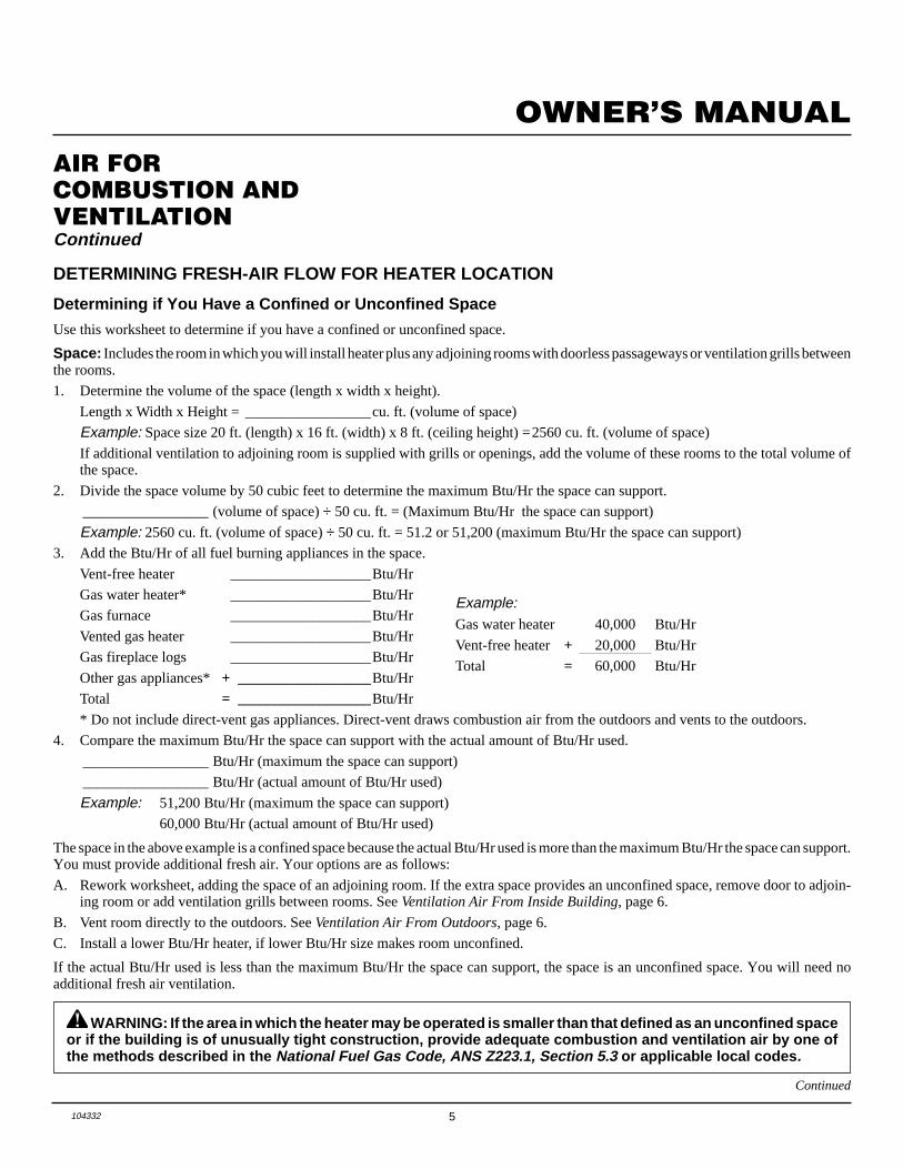
DETERMINING FRESH-AIR FLOW FOR HEATER LOCATION
Determining if You Have a Confined or Unconfined Space
Use this worksheet to determine if you have a confined or unconfined space.
Space: Includes the room in which you will install heater plus any adjoining rooms with doorless passageways or ventilation grills betweenthe rooms.
1. Determine the volume of the space (length x width x height).
Length x Width x Height = _________________cu. ft. (volume of space)
Example: Space size 20 ft. (length) x 16 ft. (width) x 8 ft. (ceiling height) =2560 cu. ft. (volume of space)
If additional ventilation to adjoining room is supplied with grills or openings, add the volume of these rooms to the total volume ofthe space.
2. Divide the space volume by 50 cubic feet to determine the maximum Btu/Hr the space can support.
_________________ (volume of space) ÷ 50 cu. ft. = (Maximum Btu/Hr the space can support)
Example: 2560 cu. ft. (volume of space) ÷ 50 cu. ft. = 51.2 or 51,200 (maximum Btu/Hr the space can support)
3. Add the Btu/Hr of all fuel burning appliances in the space.
Vent-free heater ___________________Btu/Hr
Gas water heater* ___________________Btu/Hr
Gas furnace ___________________Btu/Hr
Vented gas heater ___________________Btu/Hr
Gas fireplace logs ___________________Btu/Hr
Other gas appliances*+ __________________Btu/Hr
Total = __________________Btu/Hr
* Do not include direct-vent gas appliances. Direct-vent draws combustion air from the outdoors and vents to the outdoors.
4. Compare the maximum Btu/Hr the space can support with the actual amount of Btu/Hr used.
_________________ Btu/Hr (maximum the space can support)
_________________ Btu/Hr (actual amount of Btu/Hr used)
Example: 51,200 Btu/Hr (maximum the space can support)
60,000 Btu/Hr (actual amount of Btu/Hr used)
The space in the above example is a confined space because the actual Btu/Hr used is more than the maximum Btu/Hr the space can support.You must provide additional fresh air. Your options are as follows:
A. Rework worksheet, adding the space of an adjoining room. If the extra space provides an unconfined space, remove door to adjoin-ing room or add ventilation grills between rooms. See Ventilation Air From Inside Building, page 6.
B. Vent room directly to the outdoors. See Ventilation Air From Outdoors, page 6.
C. Install a lower Btu/Hr heater, if lower Btu/Hr size makes room unconfined.
If the actual Btu/Hr used is less than the maximum Btu/Hr the space can support, the space is an unconfined space. You will need noadditional fresh air ventilation.
Example:Gas water heater 40,000 Btu/Hr
Vent-free heater + 20,000 Btu/Hr
Total = 60,000 Btu/Hr
Continued
WARNING: If the area in which the heater may be operated is smaller than that defined as an unconfined spaceor if the building is of unusually tight construction, provide adequate combustion and ventilation air by one ofthe methods described in the National Fuel Gas Code, ANS Z223.1, Section 5.3 or applicable local codes .
6 104332
BLUE FLAME PROPANE/LP HEATER
Or Remove Door into Adjoining
Room, Option 3
Ventilation Grills Into Adjoining Room,
Option 2
12"
12"
VentilationGrills
into AdjoiningRoom,
Option 1
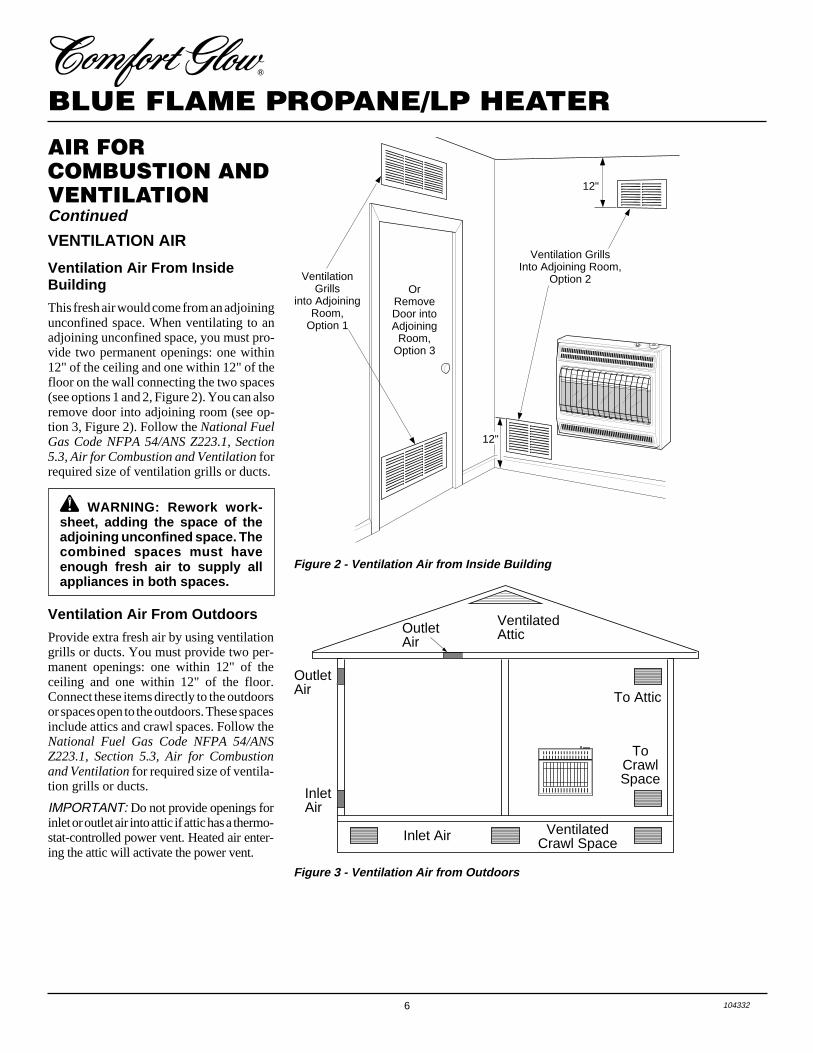
VENTILATION AIR
Ventilation Air From InsideBuilding
This fresh air would come from an adjoiningunconfined space. When ventilating to anadjoining unconfined space, you must pro-vide two permanent openings: one within12" of the ceiling and one within 12" of thefloor on the wall connecting the two spaces(see options 1 and 2, Figure 2). You can alsoremove door into adjoining room (see op-tion 3, Figure 2). Follow the National FuelGas Code NFPA 54/ANS Z223.1, Section5.3, Air for Combustion and Ventilation forrequired size of ventilation grills or ducts.
AIR FORCOMBUSTION ANDVENTILATIONContinued
Figure 2 - Ventilation Air from Inside Building
WARNING: Rework work-sheet, adding the space of theadjoining unconfined space. Thecombined spaces must haveenough fresh air to supply allappliances in both spaces.
Figure 3 - Ventilation Air from Outdoors
Ventilation Air From Outdoors
Provide extra fresh air by using ventilationgrills or ducts. You must provide two per-manent openings: one within 12" of theceiling and one within 12" of the floor.Connect these items directly to the outdoorsor spaces open to the outdoors. These spacesinclude attics and crawl spaces. Follow theNational Fuel Gas Code NFPA 54/ANSZ223.1, Section 5.3, Air for Combustionand Ventilation for required size of ventila-tion grills or ducts.
IMPORTANT: Do not provide openings forinlet or outlet air into attic if attic has a thermo-stat-controlled power vent. Heated air enter-ing the attic will activate the power vent.
OutletAir
VentilatedAttic
OutletAir
InletAir
Inlet Air Ventilated Crawl Space
To CrawlSpace
To Attic
7104332
OWNER’S MANUAL
INSTALLATION
WARNING: A qualified ser-vice person must install heater.Follow all local codes.
CHECK GAS TYPEUse only propane/LP gas. If your gas supplyis not propane/LP, do not install heater. Calldealer where you bought heater for propertype heater.
INSTALLATION ITEMSBefore installing heater, make sure you havethe items listed below.
• external regulator (supplied by installer)
• piping (check local codes)
• sealant (resistant to propane/LP gas)
• equipment shutoff valve *
• ground joint union
• test gauge connection *
• sediment trap
• tee joint
• pipe wrench
* A CSA/AGA design-certified equipmentshutoff valve with 1/8" NPT tap is an ac-ceptable alternative to test gauge connec-tion. Purchase the optional CSA/AGA de-sign-certified equipment shutoff valve fromyour dealer. See Accessories, page 18.
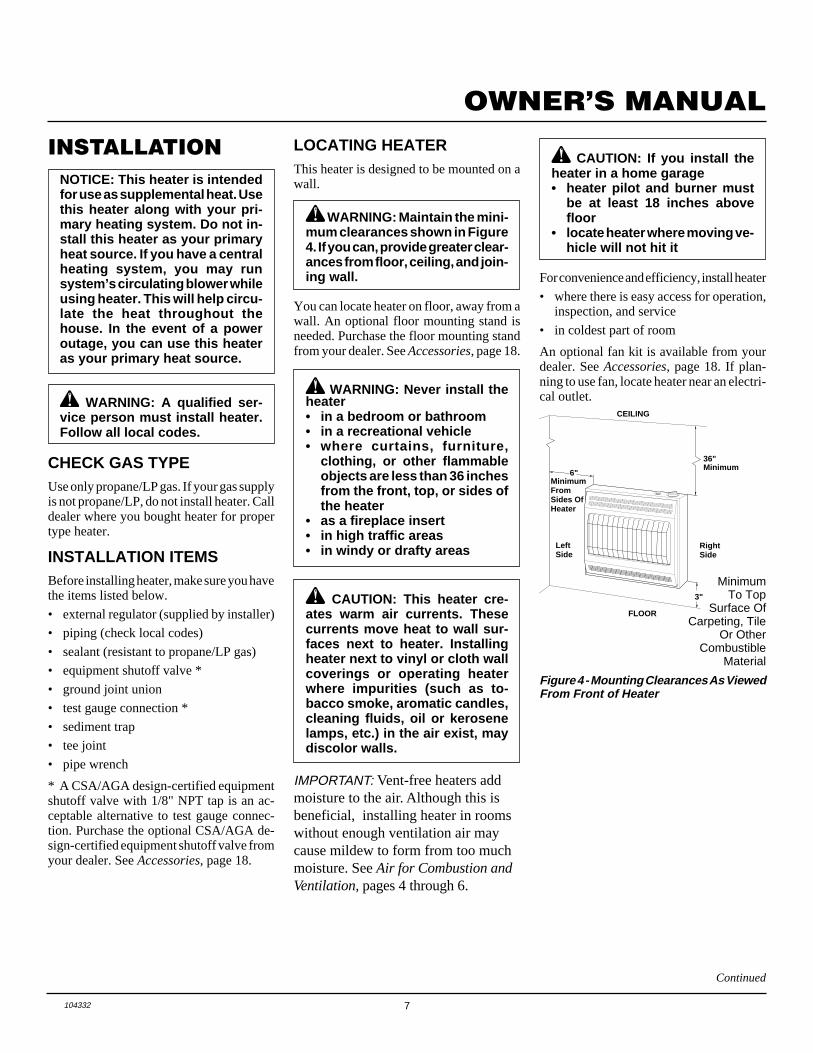
LOCATING HEATERThis heater is designed to be mounted on awall.
WARNING: Maintain the mini-mum clearances shown in Figure4. If you can, provide greater clear-ances from floor, ceiling, and join-ing wall.
You can locate heater on floor, away from awall. An optional floor mounting stand isneeded. Purchase the floor mounting standfrom your dealer. See Accessories, page 18.
WARNING: Never install theheater• in a bedroom or bathroom• in a recreational vehicle• where curtains, furniture,
clothing, or other flammableobjects are less than 36 inchesfrom the front, top, or sides ofthe heater
• as a fireplace insert• in high traffic areas• in windy or drafty areas
CAUTION: This heater cre-ates warm air currents. Thesecurrents move heat to wall sur-faces next to heater. Installingheater next to vinyl or cloth wallcoverings or operating heaterwhere impurities (such as to-bacco smoke, aromatic candles,cleaning fluids, oil or kerosenelamps, etc.) in the air exist, maydiscolor walls.
NOTICE: This heater is intendedfor use as supplemental heat. Usethis heater along with your pri-mary heating system. Do not in-stall this heater as your primaryheat source. If you have a centralheating system, you may runsystem’s circulating blower whileusing heater. This will help circu-late the heat throughout thehouse. In the event of a poweroutage, you can use this heateras your primary heat source.
Continued
IMPORTANT: Vent-free heaters addmoisture to the air. Although this isbeneficial, installing heater in roomswithout enough ventilation air maycause mildew to form from too muchmoisture. See Air for Combustion andVentilation, pages 4 through 6.
CAUTION: If you install theheater in a home garage• heater pilot and burner must
be at least 18 inches abovefloor
• locate heater where moving ve-hicle will not hit it
For convenience and efficiency, install heater
• where there is easy access for operation,inspection, and service
• in coldest part of room
An optional fan kit is available from yourdealer. See Accessories, page 18. If plan-ning to use fan, locate heater near an electri-cal outlet.
Figure 4 - Mounting Clearances As ViewedFrom Front of Heater
MinimumFromSides OfHeater
36"
3"
FLOOR
CEILING
Minimum
MinimumOf CarpeCombust
6"
LeftSide
RightSide
MinimumTo Top
Surface OfCarpeting, Tile
Or OtherCombustible
Material
8 104332
BLUE FLAME PROPANE/LP HEATER
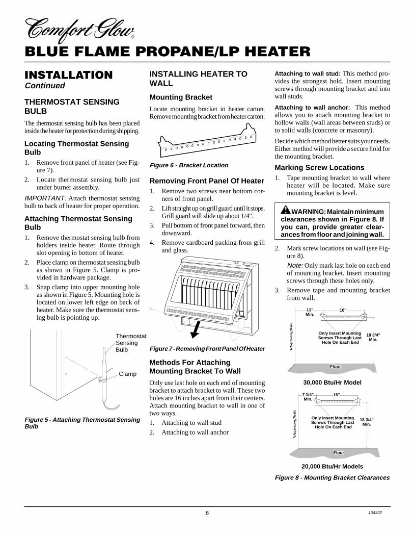
Figure 5 - Attaching Thermostat SensingBulb
Clamp
ThermostatSensingBulb
THERMOSTAT SENSINGBULBThe thermostat sensing bulb has been placedinside the heater for protection during shipping.
Locating Thermostat SensingBulb1. Remove front panel of heater (see Fig-
ure 7).
2. Locate thermostat sensing bulb justunder burner assembly.
IMPORTANT: Attach thermostat sensingbulb to back of heater for proper operation.
Attaching Thermostat SensingBulb1. Remove thermostat sensing bulb from
holders inside heater. Route throughslot opening in bottom of heater.
2. Place clamp on thermostat sensing bulbas shown in Figure 5. Clamp is pro-vided in hardware package.
3. Snap clamp into upper mounting holeas shown in Figure 5. Mounting hole islocated on lower left edge on back ofheater. Make sure the thermostat sens-ing bulb is pointing up.
INSTALLATIONContinued
INSTALLING HEATER TOWALL
Mounting Bracket
Locate mounting bracket in heater carton.Remove mounting bracket from heater carton.
Figure 6 - Bracket Location
Figure 7 - Removing Front Panel Of Heater
Methods For AttachingMounting Bracket To Wall
Only use last hole on each end of mountingbracket to attach bracket to wall. These twoholes are 16 inches apart from their centers.Attach mounting bracket to wall in one oftwo ways.
1. Attaching to wall stud
2. Attaching to wall anchor
Removing Front Panel Of Heater1. Remove two screws near bottom cor-
ners of front panel.
2. Lift straight up on grill guard until it stops.Grill guard will slide up about 1/4".
3. Pull bottom of front panel forward, thendownward.
4. Remove cardboard packing from grilland glass.
Attaching to wall stud: This method pro-vides the strongest hold. Insert mountingscrews through mounting bracket and intowall studs.
Attaching to wall anchor: This methodallows you to attach mounting bracket tohollow walls (wall areas between studs) orto solid walls (concrete or masonry).
Decide which method better suits your needs.Either method will provide a secure hold forthe mounting bracket.
Marking Screw Locations1. Tape mounting bracket to wall where
heater will be located. Make suremounting bracket is level.
30,000 Btu/Hr Model
20,000 Btu/Hr Models
2. Mark screw locations on wall (see Fig-ure 8).
Note: Only mark last hole on each endof mounting bracket. Insert mountingscrews through these holes only.
3. Remove tape and mounting bracketfrom wall.
Figure 8 - Mounting Bracket Clearances
WARNING: Maintain minimumclearances shown in Figure 8. Ifyou can, provide greater clear-ances from floor and joining wall.
18 3/4"Min.
11"Min.
16"
Adj
oini
ng W
all
Only Insert Mounting Screws Through Last
Hole On Each End
Floor
16"
18 3/4"Min.
7 1/4"Min.
Adj
oini
ng W
all
Only Insert Mounting Screws Through Last
Hole On Each End
Floor
9104332
OWNER’S MANUAL
Attaching Mounting Bracket ToWall
Note: Wall anchors, mounting screws, andspacers are in hardware package. The hard-ware package is provided with heater.
Attaching to Wall Stud method
For attaching mounting bracket to wall studs
1. Drill holes at marked locations using9/64" drill bit.
2. Place mounting bracket onto wall. Lineup last hole on each end of bracket withholes drilled in wall.
3. Insert mounting screws through bracketand into wall studs.
4. Tighten screws until mounting bracketis firmly fastened to wall studs.
Attaching to Wall Anchor Method
For attaching mounting bracket to hollowwalls (wall areas between studs) or solidwalls (concrete or masonry)
1. Drill holes at marked locations using5/16" drill bit. For solid walls (concreteor masonry), drill at least 1" deep.
2. Fold wall anchor as shown in Figure 9.
3. Insert wall anchor (wings first) intohole. Tap anchor flush to wall.
4. For thin walls (1/2" or less), insert redkey into wall anchor. Push red key to“pop” open anchor wings.IMPORTANT: Do not hammer key!For thick walls (over 1/2" thick) or solidwalls, do not pop open wings.
5. Place mounting bracket onto wall. Lineup last hole on each end of bracket withwall anchors.
6. Insert mounting screws through bracketand into wall anchors.
7. Tighten screws until mounting bracketis firmly fastened to wall.
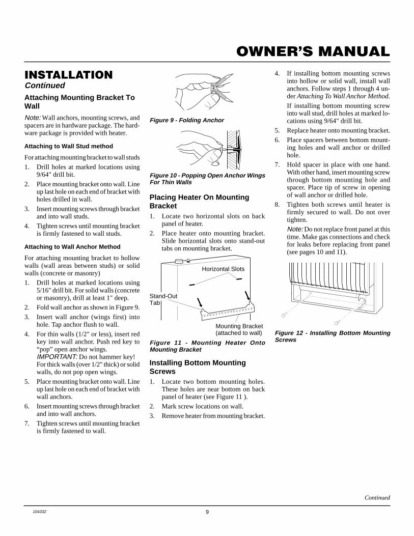
Figure 9 - Folding Anchor
INSTALLATIONContinued
Figure 10 - Popping Open Anchor WingsFor Thin Walls
Stand-OutTab
Figure 11 - Mounting Heater OntoMounting Bracket
Figure 12 - Installing Bottom MountingScrews
Horizontal Slots
Mounting Bracket(attached to wall)
Placing Heater On MountingBracket1. Locate two horizontal slots on back
panel of heater.
2. Place heater onto mounting bracket.Slide horizontal slots onto stand-outtabs on mounting bracket.
Installing Bottom MountingScrews1. Locate two bottom mounting holes.
These holes are near bottom on backpanel of heater (see Figure 11 ).
2. Mark screw locations on wall.
3. Remove heater from mounting bracket.
4. If installing bottom mounting screwsinto hollow or solid wall, install wallanchors. Follow steps 1 through 4 un-der Attaching To Wall Anchor Method.
If installing bottom mounting screwinto wall stud, drill holes at marked lo-cations using 9/64" drill bit.
5. Replace heater onto mounting bracket.
6. Place spacers between bottom mount-ing holes and wall anchor or drilledhole.
7. Hold spacer in place with one hand.With other hand, insert mounting screwthrough bottom mounting hole andspacer. Place tip of screw in openingof wall anchor or drilled hole.
8. Tighten both screws until heater isfirmly secured to wall. Do not overtighten.
Note: Do not replace front panel at thistime. Make gas connections and checkfor leaks before replacing front panel(see pages 10 and 11).
Continued
10 104332
BLUE FLAME PROPANE/LP HEATER
INSTALLATIONContinued
CONNECTING TO GASSUPPLY
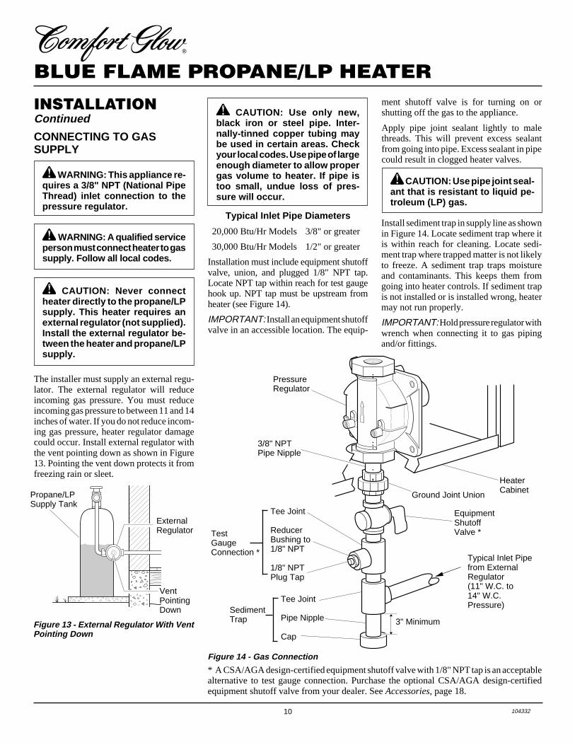
The installer must supply an external regu-lator. The external regulator will reduceincoming gas pressure. You must reduceincoming gas pressure to between 11 and 14inches of water. If you do not reduce incom-ing gas pressure, heater regulator damagecould occur. Install external regulator withthe vent pointing down as shown in Figure13. Pointing the vent down protects it fromfreezing rain or sleet.
WARNING: A qualified serviceperson must connect heater to gassupply. Follow all local codes.
Propane/LPSupply Tank
Figure 13 - External Regulator With VentPointing Down
Typical Inlet Pipe Diameters
20,000 Btu/Hr Models 3/8" or greater
30,000 Btu/Hr Models 1/2" or greater
Installation must include equipment shutoffvalve, union, and plugged 1/8" NPT tap.Locate NPT tap within reach for test gaugehook up. NPT tap must be upstream fromheater (see Figure 14).
IMPORTANT: Install an equipment shutoffvalve in an accessible location. The equip-
Install sediment trap in supply line as shownin Figure 14. Locate sediment trap where itis within reach for cleaning. Locate sedi-ment trap where trapped matter is not likelyto freeze. A sediment trap traps moistureand contaminants. This keeps them fromgoing into heater controls. If sediment trapis not installed or is installed wrong, heatermay not run properly.
IMPORTANT: Hold pressure regulator withwrench when connecting it to gas pipingand/or fittings.
CAUTION: Never connectheater directly to the propane/LPsupply. This heater requires anexternal regulator (not supplied).Install the external regulator be-tween the heater and propane/LPsupply.
CAUTION: Use only new,black iron or steel pipe. Inter-nally-tinned copper tubing maybe used in certain areas. Checkyour local codes. Use pipe of largeenough diameter to allow propergas volume to heater. If pipe istoo small, undue loss of pres-sure will occur.
CAUTION: Use pipe joint seal-ant that is resistant to liquid pe-troleum (LP) gas.
ExternalRegulator
VentPointingDown
* A CSA/AGA design-certified equipment shutoff valve with 1/8" NPT tap is an acceptablealternative to test gauge connection. Purchase the optional CSA/AGA design-certifiedequipment shutoff valve from your dealer. See Accessories, page 18.
Figure 14 - Gas Connection
ment shutoff valve is for turning on orshutting off the gas to the appliance.
Apply pipe joint sealant lightly to malethreads. This will prevent excess sealantfrom going into pipe. Excess sealant in pipecould result in clogged heater valves.
WARNING: This appliance re-quires a 3/8" NPT (National PipeThread) inlet connection to thepressure regulator.
PressureRegulator
Tee Joint
ReducerBushing to1/8" NPT
1/8" NPTPlug Tap
TestGaugeConnection *
Tee Joint
Pipe Nipple
Cap
3/8" NPTPipe Nipple
HeaterCabinet
SedimentTrap
EquipmentShutoffValve *
3" Minimum
Typical Inlet Pipefrom ExternalRegulator(11" W.C. to14" W.C.Pressure)
Ground Joint Union
11104332
OWNER’S MANUAL
INSTALLATIONContinued
Continued
CHECKING GASCONNECTIONS
Pressure Testing Gas SupplyPiping System
Test Pressures In Excess Of 1/2 PSIG(3.5 kPa)
1. Disconnect appliance with its appliancemain gas valve (control valve) and equip-ment shutoff valve from gas supply pip-ing system. Pressures in excess of 1/2 psigwill damage heater regulator.
2. Cap off open end of gas pipe whereequipment shutoff valve was connected.
3. Pressurize supply piping system by ei-ther using compressed air or openingpropane/LP supply tank valve.
4. Check all joints of gas supply pipingsystem. Apply mixture of liquid soapand water to gas joints. Bubbles form-ing show a leak.
5. Correct all leaks at once.6. Reconnect heater and equipment
shutoff valve to gas supply. Check re-connected fittings for leaks.
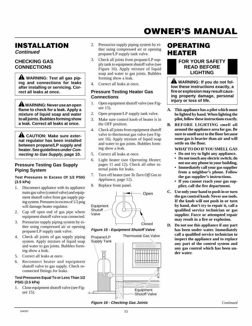
Test Pressures Equal To or Less Than 1/2PSIG (3.5 kPa)1. Close equipment shutoff valve (see Fig-
ure 15).
WARNING: Test all gas pip-ing and connections for leaksafter installing or servicing. Cor-rect all leaks at once.
WARNING: Never use an openflame to check for a leak. Apply amixture of liquid soap and waterto all joints. Bubbles forming showa leak. Correct all leaks at once.
CAUTION: Make sure exter-nal regulator has been installedbetween propane/LP supply andheater. See guidelines under Con-necting to Gas Supply , page 10.
Figure 15 - Equipment Shutoff Valve
Figure 16 - Checking Gas Joints
ONPOSIT
PO
EquipmentShutoffValve
Open
Closed
Thermostat Gas ValvePropane/LPSupply Tank
EquipmentShutoff Valve
OPERATINGHEATER
FOR YOUR SAFETYREAD BEFORE
LIGHTING
A. This appliance has a pilot which mustbe lighted by hand. When lighting thepilot, follow these instructions exactly.
B. BEFORE LIGHTING smell allaround the appliance area for gas. Besure to smell next to the floor becausesome gas is heavier than air and willsettle on the floor.WHAT TO DO IF YOU SMELL GAS• Do not try to light any appliance.• Do not touch any electric switch; do
not use any phone in your building.• Immediately call your gas supplier
from a neighbor’s phone. Followthe gas supplier’s instructions.
• If you cannot reach your gas sup-plier, call the fire department.
C. Use only your hand to push in or turnthe gas control knob. Never use tools.If the knob will not push in or turnby hand, don’t try to repair it, call aqualified service technician or gassupplier. Force or attempted repairmay result in a fire or explosion.
D. Do not use this appliance if any parthas been under water. Immediatelycall a qualified service technician toinspect the appliance and to replaceany part of the control system andany gas control which has been un-der water.
WARNING: If you do not fol-low these instructions exactly, afire or explosion may result caus-ing property damage, personalinjury or loss of life.
2. Pressurize supply piping system by ei-ther using compressed air or openingpropane/LP supply tank valve.
3. Check all joints from propane/LP sup-ply tank to equipment shutoff valve (seeFigure 16). Apply mixture of liquidsoap and water to gas joints. Bubblesforming show a leak.
4. Correct all leaks at once.
Pressure Testing Heater GasConnections1. Open equipment shutoff valve (see Fig-
ure 15).
2. Open propane/LP supply tank valve.
3. Make sure control knob of heater is inthe OFF position.
4. Check all joints from equipment shutoffvalve to thermostat gas valve (see Fig-ure 16). Apply mixture of liquid soapand water to gas joints. Bubbles form-ing show a leak.
5. Correct all leaks at once.
6. Light heater (see Operating Heater,pages 11 and 12). Check all other in-ternal joints for leaks.
7. Turn off heater (see To Turn Off Gas toAppliance, page 12).
8. Replace front panel.
12 104332
BLUE FLAME PROPANE/LP HEATER
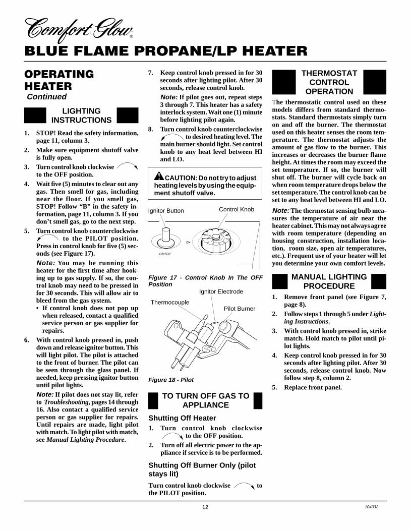
PILOT LO
OFF
HI
IGNITOR
LIGHTINGINSTRUCTIONS
1. STOP! Read the safety information,page 11, column 3.
2. Make sure equipment shutoff valveis fully open.
3. Turn control knob clockwise Clockwise
to the OFF position.4. Wait five (5) minutes to clear out any
gas. Then smell for gas, includingnear the floor. If you smell gas,STOP! Follow “B” in the safety in-formation, page 11, column 3. If youdon’t smell gas, go to the next step.
5. Turn control knob counterclockwiseC-clockwise to the PILOT position.
Press in control knob for five (5) sec-onds (see Figure 17).Note: You may be running thisheater for the first time after hook-ing up to gas supply. If so, the con-trol knob may need to be pressed infor 30 seconds. This will allow air tobleed from the gas system.• If control knob does not pop up
when released, contact a qualifiedservice person or gas supplier forrepairs.
6. With control knob pressed in, pushdown and release ignitor button. Thiswill light pilot. The pilot is attachedto the front of burner. The pilot canbe seen through the glass panel. Ifneeded, keep pressing ignitor buttonuntil pilot lights.Note: If pilot does not stay lit, referto Troubleshooting, pages 14 through16. Also contact a qualified serviceperson or gas supplier for repairs.Until repairs are made, light pilotwith match. To light pilot with match,see Manual Lighting Procedure.
Figure 17 - Control Knob In The OFFPosition
Ignitor Button Control Knob
OPERATINGHEATER Continued
Figure 18 - Pilot
CAUTION: Do not try to adjustheating levels by using the equip-ment shutoff valve.
7. Keep control knob pressed in for 30seconds after lighting pilot. After 30seconds, release control knob.Note: If pilot goes out, repeat steps3 through 7. This heater has a safetyinterlock system. Wait one (1) minutebefore lighting pilot again.
8. Turn control knob counterclockwiseC-clockwise to desired heating level. The
main burner should light. Set controlknob to any heat level between HIand LO.
TO TURN OFF GAS TOAPPLIANCE
Shutting Off Heater1. Turn control knob clockwise
Clockwise to the OFF position.2. Turn off all electric power to the ap-
pliance if service is to be performed.
Shutting Off Burner Only (pilotstays lit)
Turn control knob clockwise Clockwise tothe PILOT position.
THERMOSTATCONTROL
OPERATIONThe thermostatic control used on thesemodels differs from standard thermo-stats. Standard thermostats simply turnon and off the burner. The thermostatused on this heater senses the room tem-perature. The thermostat adjusts theamount of gas flow to the burner. Thisincreases or decreases the burner flameheight. At times the room may exceed theset temperature. If so, the burner willshut off. The burner will cycle back onwhen room temperature drops below theset temperature. The control knob can beset to any heat level between HI and LO.
Note: The thermostat sensing bulb mea-sures the temperature of air near theheater cabinet. This may not always agreewith room temperature (depending onhousing construction, installation loca-tion, room size, open air temperatures,etc.). Frequent use of your heater will letyou determine your own comfort levels.
MANUAL LIGHTINGPROCEDURE
1. Remove front panel (see Figure 7,page 8).
2. Follow steps 1 through 5 under Light-ing Instructions.
3. With control knob pressed in, strikematch. Hold match to pilot until pi-lot lights.
4. Keep control knob pressed in for 30seconds after lighting pilot. After 30seconds, release control knob. Nowfollow step 8, column 2.
5. Replace front panel.
Ignitor Electrode
Pilot BurnerThermocouple
13104332
OWNER’S MANUAL
INSPECTINGBURNERCheck pilot flame pattern and burner flamepattern often.
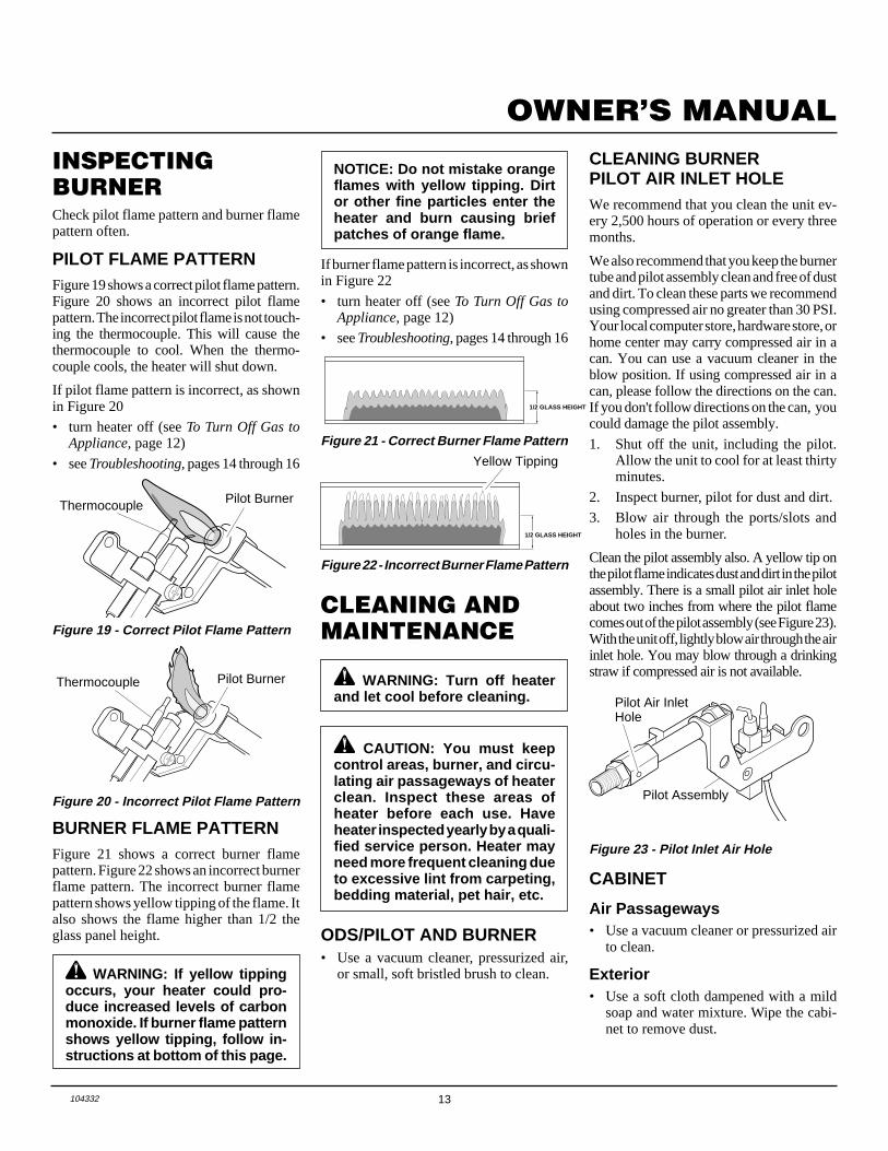
PILOT FLAME PATTERNFigure 19 shows a correct pilot flame pattern.Figure 20 shows an incorrect pilot flamepattern. The incorrect pilot flame is not touch-ing the thermocouple. This will cause thethermocouple to cool. When the thermo-couple cools, the heater will shut down.
If pilot flame pattern is incorrect, as shownin Figure 20
• turn heater off (see To Turn Off Gas toAppliance, page 12)
• see Troubleshooting, pages 14 through 16
Figure 19 - Correct Pilot Flame Pattern
Figure 20 - Incorrect Pilot Flame Pattern
NOTICE: Do not mistake orangeflames with yellow tipping. Dirtor other fine particles enter theheater and burn causing briefpatches of orange flame.
1/2 GLASS HEIGHT
1/2 GLASS HEIGHT
Yellow Tipping
WARNING: If yellow tippingoccurs, your heater could pro-duce increased levels of carbonmonoxide. If burner flame patternshows yellow tipping, follow in-structions at bottom of this page.
Figure 22 - Incorrect Burner Flame Pattern
Figure 21 - Correct Burner Flame Pattern
BURNER FLAME PATTERNFigure 21 shows a correct burner flamepattern. Figure 22 shows an incorrect burnerflame pattern. The incorrect burner flamepattern shows yellow tipping of the flame. Italso shows the flame higher than 1/2 theglass panel height.
If burner flame pattern is incorrect, as shownin Figure 22
• turn heater off (see To Turn Off Gas toAppliance, page 12)
• see Troubleshooting, pages 14 through 16
CLEANING ANDMAINTENANCE
ODS/PILOT AND BURNER• Use a vacuum cleaner, pressurized air,
or small, soft bristled brush to clean.
WARNING: Turn off heaterand let cool before cleaning.
CAUTION: You must keepcontrol areas, burner, and circu-lating air passageways of heaterclean. Inspect these areas ofheater before each use. Haveheater inspected yearly by a quali-fied service person. Heater mayneed more frequent cleaning dueto excessive lint from carpeting,bedding material, pet hair, etc.
Figure 23 - Pilot Inlet Air Hole
Pilot Assembly
Pilot Air InletHole
CLEANING BURNERPILOT AIR INLET HOLEWe recommend that you clean the unit ev-ery 2,500 hours of operation or every threemonths.
We also recommend that you keep the burnertube and pilot assembly clean and free of dustand dirt. To clean these parts we recommendusing compressed air no greater than 30 PSI.Your local computer store, hardware store, orhome center may carry compressed air in acan. You can use a vacuum cleaner in theblow position. If using compressed air in acan, please follow the directions on the can.If you don't follow directions on the can, youcould damage the pilot assembly.
1. Shut off the unit, including the pilot.Allow the unit to cool for at least thirtyminutes.
2. Inspect burner, pilot for dust and dirt.
3. Blow air through the ports/slots andholes in the burner.
Clean the pilot assembly also. A yellow tip onthe pilot flame indicates dust and dirt in the pilotassembly. There is a small pilot air inlet holeabout two inches from where the pilot flamecomes out of the pilot assembly (see Figure 23).With the unit off, lightly blow air through the airinlet hole. You may blow through a drinkingstraw if compressed air is not available.
CABINET
Air Passageways• Use a vacuum cleaner or pressurized air
to clean.
Exterior• Use a soft cloth dampened with a mild
soap and water mixture. Wipe the cabi-net to remove dust.
Thermocouple Pilot Burner
Pilot BurnerThermocouple
14 104332
BLUE FLAME PROPANE/LP HEATER
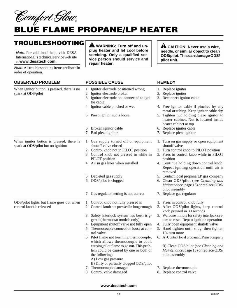
TROUBLESHOOTING WARNING: Turn off and un-plug heater and let cool beforeservicing. Only a qualified ser-vice person should service andrepair heater.
CAUTION: Never use a wire,needle, or similar object to cleanODS/pilot. This can damage ODS/pilot unit.
POSSIBLE CAUSE
1. Ignitor electrode positioned wrong2. Ignitor electrode broken3. Ignitor electrode not connected to igni-
tor cable4. Ignitor cable pinched or wet
5. Piezo ignitor nut is loose
6. Broken ignitor cable7. Bad piezo ignitor
1. Gas supply turned off or equipmentshutoff valve closed
2. Control knob not in PILOT position3. Control knob not pressed in while in
PILOT position4. Air in gas lines when installed
5. Depleted gas supply6. ODS/pilot is clogged
7. Gas regulator setting is not correct
1. Control knob not fully pressed in2. Control knob not pressed in long enough
3. Safety interlock system has been trig-gered (thermostat models only)
4. Equipment shutoff valve not fully open5. Thermocouple connection loose at con-
trol valve6. Pilot flame not touching thermocouple,
which allows thermocouple to cool,causing pilot flame to go out. This prob-lem could be caused by one or both ofthe following:A) Low gas pressureB) Dirty or partially clogged ODS/pilot
7. Thermocouple damaged8. Control valve damaged
REMEDY
1. Replace ignitor2. Replace ignitor3. Reconnect ignitor cable
4. Free ignitor cable if pinched by anymetal or tubing. Keep ignitor cable dry
5. Tighten nut holding piezo ignitor toheater cabinet. Nut is located insideheater cabinet at top
6. Replace ignitor cable7. Replace piezo ignitor
1. Turn on gas supply or open equipmentshutoff valve
2. Turn control knob to PILOT position3. Press in control knob while in PILOT
position4. Continue holding down control knob.
Repeat igniting operation until air isremoved
5. Contact local propane/LP gas company6. Clean ODS/pilot (see Cleaning and
Maintenance, page 13) or replace ODS/pilot assembly
7. Replace gas regulator
1. Press in control knob fully2. After ODS/pilot lights, keep control
knob pressed in 30 seconds3. Wait one minute for safety interlock sys-
tem to reset. Repeat ignition operation4. Fully open equipment shutoff valve5. Hand tighten until snug, then tighten
1/4 turn more6. A) Contact local propane/LP gas company
B) Clean ODS/pilot (see Cleaning andMaintenance, page 13) or replace ODS/pilot assembly
7. Replace thermocouple8. Replace control valve
OBSERVED PROBLEM
When ignitor button is pressed, there is nospark at ODS/pilot
When ignitor button is pressed, there isspark at ODS/pilot but no ignition
ODS/pilot lights but flame goes out whencontrol knob is released
Note: For additional help, visit DESAInternational’s technical service web siteat www.desatech.com .
Note: All troubleshooting items are listed inorder of operation.
www.desatech.com
15104332
OWNER’S MANUAL
Continued
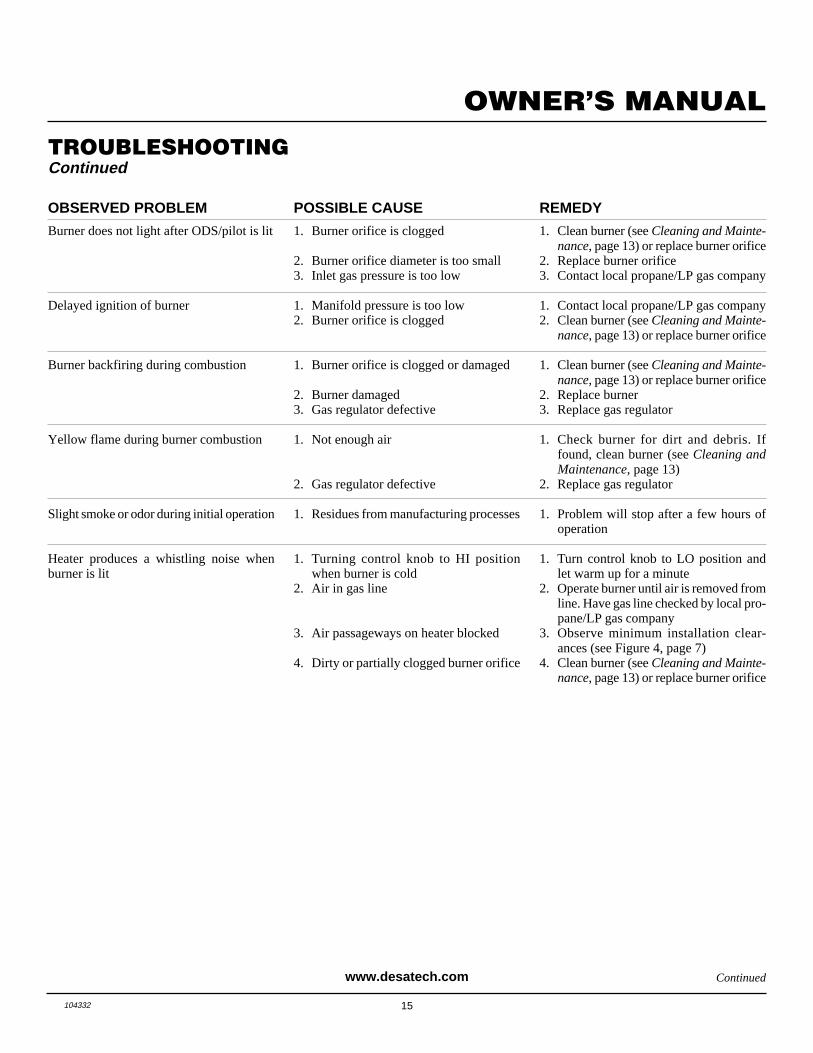
TROUBLESHOOTINGContinued
OBSERVED PROBLEM
Burner does not light after ODS/pilot is lit
Delayed ignition of burner
Burner backfiring during combustion
Yellow flame during burner combustion
Slight smoke or odor during initial operation
Heater produces a whistling noise whenburner is lit
REMEDY
1. Clean burner (see Cleaning and Mainte-nance, page 13) or replace burner orifice
2. Replace burner orifice3. Contact local propane/LP gas company
1. Contact local propane/LP gas company2. Clean burner (see Cleaning and Mainte-
nance, page 13) or replace burner orifice
1. Clean burner (see Cleaning and Mainte-nance, page 13) or replace burner orifice
2. Replace burner3. Replace gas regulator
1. Check burner for dirt and debris. Iffound, clean burner (see Cleaning andMaintenance, page 13)
2. Replace gas regulator
1. Problem will stop after a few hours ofoperation
1. Turn control knob to LO position andlet warm up for a minute
2. Operate burner until air is removed fromline. Have gas line checked by local pro-pane/LP gas company
3. Observe minimum installation clear-ances (see Figure 4, page 7)
4. Clean burner (see Cleaning and Mainte-nance, page 13) or replace burner orifice
POSSIBLE CAUSE
1. Burner orifice is clogged
2. Burner orifice diameter is too small3. Inlet gas pressure is too low
1. Manifold pressure is too low2. Burner orifice is clogged
1. Burner orifice is clogged or damaged
2. Burner damaged3. Gas regulator defective
1. Not enough air
2. Gas regulator defective
1. Residues from manufacturing processes
1. Turning control knob to HI positionwhen burner is cold
2. Air in gas line
3. Air passageways on heater blocked
4. Dirty or partially clogged burner orifice
www.desatech.com
16 104332
BLUE FLAME PROPANE/LP HEATER
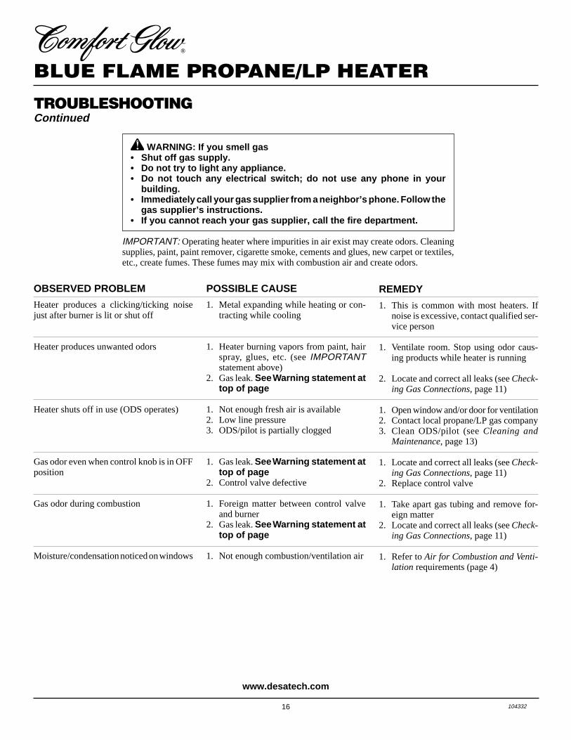
TROUBLESHOOTINGContinued
WARNING: If you smell gas• Shut off gas supply.• Do not try to light any appliance.• Do not touch any electrical switch; do not use any phone in your
building.• Immediately call your gas supplier from a neighbor’s phone. Follow the
gas supplier’s instructions.• If you cannot reach your gas supplier, call the fire department.
POSSIBLE CAUSE
1. Metal expanding while heating or con-tracting while cooling
1. Heater burning vapors from paint, hairspray, glues, etc. (see IMPORTANTstatement above)
2. Gas leak. See Warning statement attop of page
1. Not enough fresh air is available2. Low line pressure3. ODS/pilot is partially clogged
1. Gas leak. See Warning statement attop of page
2. Control valve defective
1. Foreign matter between control valveand burner
2. Gas leak. See Warning statement attop of page
1. Not enough combustion/ventilation air
OBSERVED PROBLEM
Heater produces a clicking/ticking noisejust after burner is lit or shut off
Heater produces unwanted odors
Heater shuts off in use (ODS operates)
Gas odor even when control knob is in OFFposition
Gas odor during combustion
Moisture/condensation noticed on windows
REMEDY
1. This is common with most heaters. Ifnoise is excessive, contact qualified ser-vice person
1. Ventilate room. Stop using odor caus-ing products while heater is running
2. Locate and correct all leaks (see Check-ing Gas Connections, page 11)
1. Open window and/or door for ventilation2. Contact local propane/LP gas company3. Clean ODS/pilot (see Cleaning and
Maintenance, page 13)
1. Locate and correct all leaks (see Check-ing Gas Connections, page 11)
2. Replace control valve
1. Take apart gas tubing and remove for-eign matter
2. Locate and correct all leaks (see Check-ing Gas Connections, page 11)
1. Refer to Air for Combustion and Venti-lation requirements (page 4)
IMPORTANT: Operating heater where impurities in air exist may create odors. Cleaningsupplies, paint, paint remover, cigarette smoke, cements and glues, new carpet or textiles,etc., create fumes. These fumes may mix with combustion air and create odors.
www.desatech.com
17104332
OWNER’S MANUAL
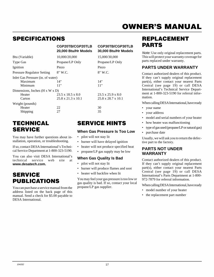
TECHNICALSERVICEYou may have further questions about in-stallation, operation, or troubleshooting.
If so, contact DESA International’s Techni-cal Service Department at 1-800-323-5190.
You can also visit DESA International’stechnical service web site atwww.desatech.com.
CGP20TB/CGP20TLB CGP30TB/CGP30TLB20,000 Btu/Hr Models 30,000 Btu/Hr Models
Btu (Variable) 10,000/20,000 15,000/30,000
Type Gas Propane/LP Only Propane/LP Only
Ignition Piezo Piezo
Pressure Regulator Setting 8" W.C. 8" W.C.
Inlet Gas Pressure (in. of water)Maximum 14" 14"Minimum 11" 11"
Dimensions, Inches (H x W x D)Heater 23.5 x 18.5 x 8.0 23.5 x 25.9 x 8.0Carton 25.8 x 21.3 x 10.1 25.8 x 28.7 x 10.1
Weight (pounds)Heater 22 30Shipping 27 35
SPECIFICATIONS
SERVICEPUBLICATIONSYou can purchase a service manual from theaddress listed on the back page of thismanual. Send a check for $5.00 payable toDESA International.
When Gas Pressure Is Too Low• pilot will not stay lit
• burner will have delayed ignition
• heater will not produce specified heat
• propane/LP gas supply may be low
When Gas Quality Is Bad• pilot will not stay lit
• burner will produce flames and soot
• heater will backfire when lit
You may feel your gas pressure is too low orgas quality is bad. If so, contact your localpropane/LP gas supplier.
SERVICE HINTS
REPLACEMENTPARTSNote: Use only original replacement parts.This will protect your warranty coverage forparts replaced under warranty.
PARTS UNDER WARRANTYContact authorized dealers of this product.If they can’t supply original replacementpart(s), either contact your nearest PartsCentral (see page 19) or call DESAInternational’s Technical Service Depart-ment at 1-800-323-5190 for referral infor-mation.
When calling DESA International, have ready
• your name
• your address
• model and serial numbers of your heater
• how heater was malfunctioning
• type of gas used (propane/LP or natural gas)
• purchase date
Usually, we will ask you to return the defec-tive part to the factory.
PARTS NOT UNDERWARRANTYContact authorized dealers of this product.If they can’t supply original replacementpart(s), either contact your nearest PartsCentral (see page 19) or call DESAInternational’s Parts Department at 1-800-972-7879 for referral information.
When calling DESA International, have ready
• model number of your heater
• the replacement part number
18 104332
BLUE FLAME PROPANE/LP HEATER
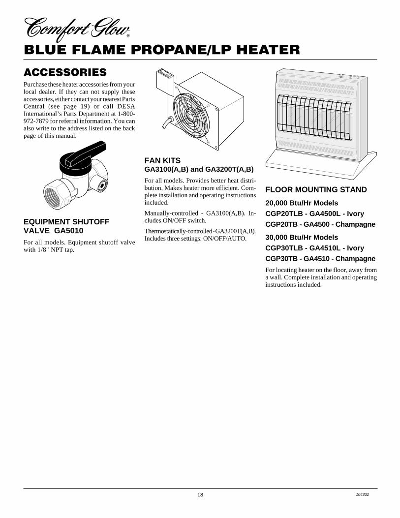
ACCESSORIES
EQUIPMENT SHUTOFFVALVE GA5010For all models. Equipment shutoff valvewith 1/8" NPT tap.
Purchase these heater accessories from yourlocal dealer. If they can not supply theseaccessories, either contact your nearest PartsCentral (see page 19) or call DESAInternational’s Parts Department at 1-800-972-7879 for referral information. You canalso write to the address listed on the backpage of this manual.
FLOOR MOUNTING STAND
20,000 Btu/Hr ModelsCGP20TLB - GA4500L - IvoryCGP20TB - GA4500 - Champagne
30,000 Btu/Hr ModelsCGP30TLB - GA4510L - IvoryCGP30TB - GA4510 - Champagne
For locating heater on the floor, away froma wall. Complete installation and operatinginstructions included.
FAN KITSGA3100(A,B) and GA3200T(A,B)
For all models. Provides better heat distri-bution. Makes heater more efficient. Com-plete installation and operating instructionsincluded.
Manually-controlled - GA3100(A,B). In-cludes ON/OFF switch.
Thermostatically-controlled - GA3200T(A,B).Includes three settings: ON/OFF/AUTO.
19104332
OWNER’S MANUALThese Parts Centrals are privately owned businesses. They have agreed to support ourcustomer’s needs by providing original replacement parts and accessories.
Baltimore Electric1348 Dixwell AvenueHamden, CT 06514-03221-800-397-7553203-248-7553Parts Department
Portable Heater Parts342 N. County Rd. 400 EastValparaiso, IN 46383-9704All States219-462-74411-800-362-6951sales@[email protected]
FBD1349 Adams StreetBowling Green, KY 42103-3414270-846-11991-800-654-8534Fax: [email protected]
Master Parts Dist.1251 Mound Ave. NWGrand Rapids, MI 49504-2672616-791-05051-800-446-1446Fax: 616-791-8270www.nbmc.com
Washer Equipment Co.1715 Main StreetKansas City, MO 64108-2195KS, MO, AR816-842-3911www.washerparts.com
East Coast Energy Products707 BroadwayW. Long Branch, NJ 07764-1542732-870-88091-800-755-8809www.njplaza.com/ecep
Tarantin Tank Co.P.O. Box 6129Freehold, NJ 07728-6129908-780-93401-800-922-0724www.tarantin.com
Heater and Fireplace Store58 Halbe LaneCape May Court, NJ 08210-1110609-390-9774Parts Department
Dayton HardwareP.O. Box 275North Dayton StationDayton, OH 45404-0275All States937-258-3721OH 1-800-762-3426
Halco Enterprises208 Carter Drive, Unit 21West Chester, PA 19382-4500610-430-77171-800-368-0803www.halcoenterprises.com
LA Porte’s Parts & Service2444 N. 5th StreetHartsville, SC 29550-7704803-332-0191Parts Department
Cans Unlimited, Inc.P.O. Box 645Taylor, SC 29687-0013All [email protected]
PARTSCENTRALS
20 104332
BLUE FLAME PROPANE/LP HEATER
11-1
11-2
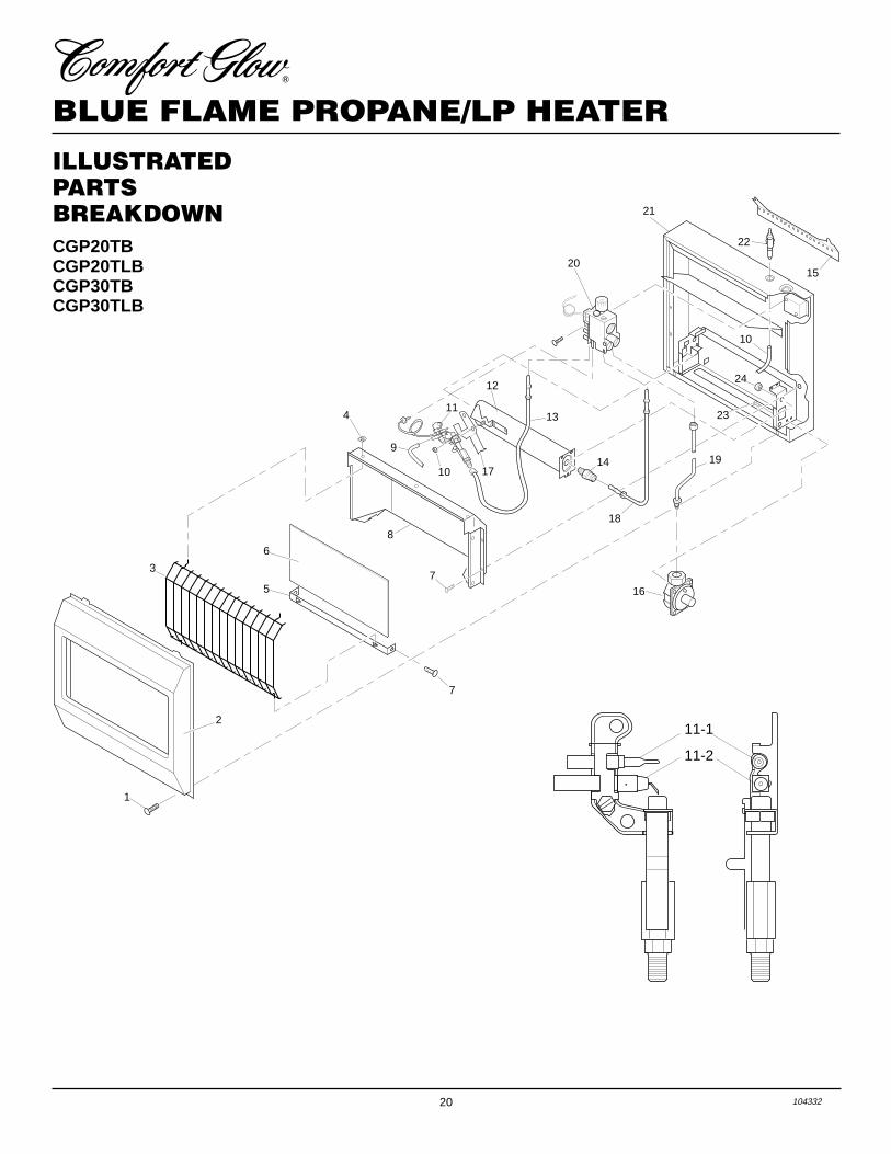
CGP20TBCGP20TLBCGP30TBCGP30TLB
ILLUSTRATEDPARTSBREAKDOWN
1
2
3
4
5
6
7
8
9
10
10
11
12
13
14
16
18
19
20
21
22
15
23
24
17
7
21104332
OWNER’S MANUAL
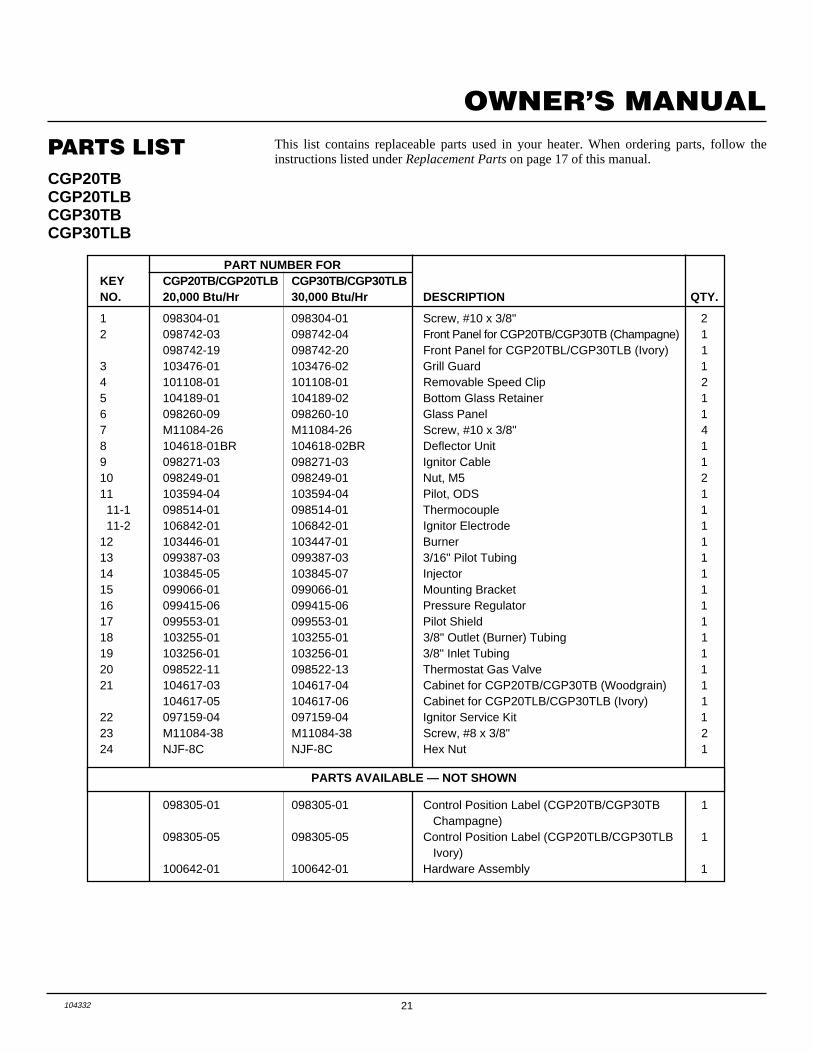
PARTS LISTCGP20TBCGP20TLBCGP30TBCGP30TLB
This list contains replaceable parts used in your heater. When ordering parts, follow theinstructions listed under Replacement Parts on page 17 of this manual.
PART NUMBER FORKEY CGP20TB/CGP20TLB CGP30TB/CGP30TLBNO. 20,000 Btu/Hr 30,000 Btu/Hr DESCRIPTION QTY.
1 098304-01 098304-01 Screw, #10 x 3/8" 22 098742-03 098742-04 Front Panel for CGP20TB/CGP30TB (Champagne) 1
098742-19 098742-20 Front Panel for CGP20TBL/CGP30TLB (Ivory) 13 103476-01 103476-02 Grill Guard 14 101108-01 101108-01 Removable Speed Clip 25 104189-01 104189-02 Bottom Glass Retainer 16 098260-09 098260-10 Glass Panel 17 M11084-26 M11084-26 Screw, #10 x 3/8" 48 104618-01BR 104618-02BR Deflector Unit 19 098271-03 098271-03 Ignitor Cable 110 098249-01 098249-01 Nut, M5 211 103594-04 103594-04 Pilot, ODS 1 11-1 098514-01 098514-01 Thermocouple 1 11-2 106842-01 106842-01 Ignitor Electrode 112 103446-01 103447-01 Burner 113 099387-03 099387-03 3/16" Pilot Tubing 114 103845-05 103845-07 Injector 115 099066-01 099066-01 Mounting Bracket 116 099415-06 099415-06 Pressure Regulator 117 099553-01 099553-01 Pilot Shield 118 103255-01 103255-01 3/8" Outlet (Burner) Tubing 119 103256-01 103256-01 3/8" Inlet Tubing 120 098522-11 098522-13 Thermostat Gas Valve 121 104617-03 104617-04 Cabinet for CGP20TB/CGP30TB (Woodgrain) 1
104617-05 104617-06 Cabinet for CGP20TLB/CGP30TLB (Ivory) 122 097159-04 097159-04 Ignitor Service Kit 123 M11084-38 M11084-38 Screw, #8 x 3/8" 224 NJF-8C NJF-8C Hex Nut 1
PARTS AVAILABLE — NOT SHOWN
098305-01 098305-01 Control Position Label (CGP20TB/CGP30TB 1 Champagne)
098305-05 098305-05 Control Position Label (CGP20TLB/CGP30TLB 1 Ivory)
100642-01 100642-01 Hardware Assembly 1
KEEP THIS WARRANTY
WARRANTY INFORMATION
Always specify model and serial numbers when communicating with the factory.
We reserve the right to amend these specifications at any time without notice. The only warranty applicable is our standard written warranty.We make no other warranty, expressed or implied.
Model
Serial No.
Date Purchased
LIMITED WARRANTYCOMFORT GLOW VENT-FREE PROPANE/LP GAS HEATERS
DESA International warrants this product to be free from defects in materials and components for two (2) years from the date of firstpurchase, provided that the product has been properly installed, operated and maintained in accordance with all applicable instructions.To make a claim under this warranty the Bill of Sale or cancelled check must be presented.
This warranty is extended only to the original retail purchaser. This warranty covers the cost of part(s) required to restore this heater to properoperating condition and an allowance for labor when provided by a DESA Authorized Service Center. Warranty part(s) MUST be obtainedthrough authorized dealers of this product and/or DESA International who will provide original factory replacement parts. Failure to useoriginal factory replacement parts voids this warranty. The heater MUST be installed by a qualified installer in accordance with all localcodes and instructions furnished with the unit.
This warranty does not apply to parts that are not in original condition because of normal wear and tear, or parts that fail or become damagedas a result of misuse, accidents, lack of proper maintenance or defects caused by improper installation. Travel, diagnostic cost, labor,transportation and any and all such other costs related to repairing a defective heater will be the responsibility of the owner.
TO THE FULL EXTENT ALLOWED BY THE LAW OF THE JURISDICTION THAT GOVERNS THE SALE OF THE PRODUCT;THIS EXPRESS WARRANTY EXCLUDES ANY AND ALL OTHER EXPRESSED WARRANTIES AND LIMITS THE DURATIONOF ANY AND ALL IMPLIED WARRANTIES, INCLUDING WARRANTIES OF MERCHANTABILITY AND FITNESS FOR APARTICULAR PURPOSE TO TWO (2) YEARS FROM THE DATE OF FIRST PURCHASE; AND DESA INTERNATIONAL’SLIABILITY IS HEREBY LIMITED TO THE PURCHASE PRICE OF THE PRODUCT AND DESA INTERNATIONAL SHALL NOTBE LIABLE FOR ANY OTHER DAMAGES WHATSOEVER INCLUDING INDIRECT, INCIDENTAL OR CONSEQUENTIALDAMAGES.
Some states do not allow a limitation on how long an implied warranty lasts or an exclusion or limitation of incidental or consequentialdamages, so the above limitation on implied warranties, or exclusion or limitation on damages may not apply to you.
This warranty gives you specific legal rights, and you may also have other rights that vary from state to state.
For information about this warranty write:
104332-01Rev. C02/00
2701 Industrial DriveP.O. Box 90004Bowling Green, KY 42102-9004
www.desatech.com
INTERNATIONAL
NOT A UPC
104332 01