Embed Size (px)
Citation preview
Brodogradnja/Shipbuilding/Open access Volume 68 Number 2, 2017
1
M. M. Moustafa
W. Yehia
http://dx.doi.org/10.21278/brod68201 ISSN 0007-215X
eISSN 1845-5859
SQUAT ASSESSMENT FOR SAFE NAVIGATION OF RIVER NILE
CRUISERS
UDC 629.5.553:629.5.015.2: 629.5.012.442
Review paper
Summary
In recent years a great deal of research efforts in ship hydromechanics have been
devoted to practical navigation problems in moving larger ships safely into existing harbors
and inland waterways. An area of particular concern is the prediction of ship squat in shallow
or restricted waters at different speeds. Squat may cause grounding of the ship which result in
severe damage to the ship, and consequently higher repair bills and off hire losses.
River Nile cruisers are encountering squat every movement due to lacking water depth
and stand up to grounding risk day after day. In this paper a series of simple but practical
useful theoretical models concerning ship squat problems in shallow waterways are discussed.
Luxor-Aswan is a selected waterway for the present study. In the course of this study,
characteristics of Luxor-Aswan waterway and main feature of existing Nile cruisers are
outlined.
Finally, theoretical squat analysis of a candidate Nile cruiser has been presented. The
results show the position and magnitude of maximum squat, grounding speed has been also
identified. It has been found that masters awareness of squat phenomenon and its prediction
for each specific vessel is of great concern for vessel safety. This work can be useful for ship
designers, naval architects and naval officers, who have to be aware of squat effects, with a
specific end goal to avoid any squat related accidents.
Key words: Ship squat; River Nile Cruisers; Luxor-Aswan Waterway.
1. Introduction
Most maritime professionals may genuinely say that they know about “squat” - the
sinkage and trim that a vessel experiences when operating in shallow water or in a channel.
There is developing evidence, however, that most masters do not fully appreciate the serious
potential magnitude of squat effects. For example, recent analyses, highly publicized maritime
accidents have revealed that squat was a contributing factor. It also comes as a surprise to
many that both the U.S. Coast Guard (USCG) and the International Maritime Organization
(IMO) require a prediction of squat effect, and that squat effect calculations are a
recommended part of the ISM Code, STCW training and the International Chamber of
M. M. Moustafa, W. Yehia. Squat Assessment for Safe Navigation of River Nile Cruisers
2
Shipping (ICS) Bridge Procedures Guide. This deficiency in understanding such a critical
design topic is quite surprising given the extensive research and publications on squat.
However, it seems to be that the design community has deemed squat be relatively
unimportant [1]. When the problem of ship squat belongs to a passenger or cruise vessels the
consequences became worthy; when a ship grounds due to excessive squat ship owners may
be faced with the following costs:
1. A large repair bill,
2. Loss of passenger bookings in the weeks following a grounding,
3. Compensation for passengers already booked,
4. Compensation claims for oil spillage, if applied,
5. Compensation claims for loss of life, if applied.
The presence of locks through Luxor -Aswan waterway and shallow water nature of River
Nile represent several constraints on the dimensions of River Nile cruisers [2], where, this
ship type has tended to be shorter in length and wider in breadth. Also, River Nile cruisers are
characterized by great values of the hull block coefficient (CB) in order to achieve a larger
displacement at small draught moreover, to gain maximum capacity and revenue. This has
prompt reporting grounding accidents due squat. Therefore, this paper presents a useful
guideline to assess every specific case with its specific operation conditions by a quick and
simple strategy in order to determine the degree of grounding risk stemmed by squat in
shallow water.
2. Underkeel clearance
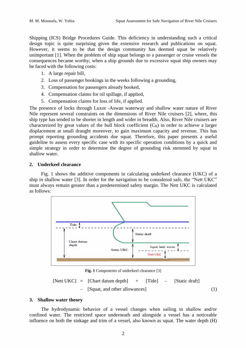
Fig. 1 shows the additive components in calculating underkeel clearance (UKC) of a
ship in shallow water [3]. In order for the navigation to be considered safe, the “Nett UKC”
must always remain greater than a predetermined safety margin. The Nett UKC is calculated
as follows:
Fig. 1 Components of underkeel clearance [3]
[Nett UKC] = [Chart datum depth] + [Tide] – [Static draft]
– [Squat, and other allowances] (1)
3. Shallow water theory
The hydrodynamic behavior of a vessel changes when sailing in shallow and/or
confined water. The restricted space underneath and alongside a vessel has a noticeable
influence on both the sinkage and trim of a vessel, also known as squat. The water depth (H)
M. M. Moustafa, W. Yehia. Squat Assessment for Safe Navigation of River Nile Cruisers
3
and the mean draught (T) of the static ship are broadly used as the parameters to characterize
shallow water. If the ratio H/T drops below 1.5, one will, in general, experience a measurable
change in the draught of the ship (sinkage). As H/T approaches 1.0 (grounding), the effect of
shallow water increases significantly. Tuck [4] presented an analytical solution for squat of
slender hull vessel traveling in open water. In the subcritical domain, he proved for laterally
open water conditions of constant water depth (H) that the sinkage and trim of a vessel sailing
at a steady speed (V) is proportional to depth Froude number (Fnh).
Tuck’s theory was extended to dredged channels by Beck [5] with a matching of
solutions between the deep and shallow regions of the cross section. Naghdi and Rubin [6]
solved Tuck’s problem using a nonlinear steady state solution of the differential equations of
the theory of a thin ship. Shallow water theory of Tuck predicts ship squat for the critical
speed value corresponding to Fnh =1. On the other hand, based on the Bernoulli principle and
conservation of mass, Dand and Ferguson [7] and Gourlay [8] give a blockage dependent
critical speed range instead of one particular critical speed value. Also, they depended upon
experimental research to extend their theoretical developments towards different bottom
conditions and very wide waterways. Dand [9] proposed a correction for the effect of the
propeller and applied the effective width parameter (W) to cope with large or even infinite
canal widths.
As the ship is generally not symmetrical about its half-length and because of the viscous
effects of water, the changes in pressure are not identical for the fore and aft parts of the hull.
This causes the ship to trim forward or astern depending on the hull shape. Thus, the
magnitude of squat depends on the hull shape, the side and under-keel clearance and the speed
through the water. Briggs [10] presented an comprehensive overview of publications and
calculation methods related to bow squat based on physical model tests and field
measurements for different channel configurations, ship types, and loading characteristics.
These formulae can be used easily to calculate bow squat by masters navigating in shallow
water to overcome grounding.
4. Slender versus fuller ships
When a ship proceeds through water, she pushes water ahead of bow. In order not to
leave a hole in the water, this volume of water must return down the sides and under the
bottom of the ship. The streamlines of return flow are accelerated under the ship. This causes
a drop in pressure, resulting in the ship dropping vertically in the water. As well as dropping
vertically, the ship generally trims forward or aft depending on the vessel’s block coefficient
(CB). The overall decrease in the static underkeel clearance “UKC”, forward or aft, is called
ship squat. Thus, ship squat is made up of two components, namely mean bodily sinkage plus
a trimming effect.
Experimental measurements have shown that bow squat is greater in magnitude than
trim; thus it has more effect on grounding. It has been observed that the variation of squat
follows the same trend for various ship types although the magnitude differs from slender to
full forms. The results portray that full form ships such as tankers trim more by the bow than
the slender hull forms. If a ship moves forward with a very high speed in shallow water, then
grounding due to excessive squat could occur at the bow or at the stern. Therefore, location of
maximum squat can be explained as follows [11]:
1. If CB > 0.70, then maximum squat will occur at the bow,
2. If CB < 0.70, then maximum squat will occur at the stern,
3. If CB is very near to 0.70, then, squat will consist only of mean bodily sinkage with
no trimming effects.
M. M. Moustafa, W. Yehia. Squat Assessment for Safe Navigation of River Nile Cruisers
4
Some ships have a static trim when they are stationary. This static trim will decide the
position of maximum squat while the ship is underway. For example, if a ship has static trim
by stern, then she will have dynamic trim in the same direction as the static trim. In other
words, she will have increased trim and could possibly run aground at her stern.
5. Factors affecting ship squat
All recent research indicates that ship squat relies on upon ship characteristics and
channel configurations. The most important factors influencing the size of ship squat are as
follows [11]:
1. Ship speed (V) is the most important factor influencing ship squat. Detailed analysis
has shown that squat varies as speed to the power of 2.08. However, squat can be
said to vary approximately with the speed squared.
2. The block coefficient (CB) is another factor which directly influences squat. Full-
form ships such as oil tankers undergo more squat than passenger ships which have
fine hull form.
3. The blockage factor (S) is another important factor affecting ship squat. This factor
can be defined as the ratio of the underwater cross-section area of ship at amidships
(AS) to the cross-section area of the canal or river (AC). Blockage factor (S) can be
calculated as follows:
HW
TBS
AA
C
S
.
. (2)
Since an open water channel has no channel width (W), an effective channel width
(Weff) can be used as follows [12]:
BCWLW eff
1
24577. (3)
4. Water depth (H)/ship draft (T) also affects ship squat. At a specified ship speed, ship
squat increases as depth to draft (H/T) ratio decreases.
5. As to the nearness of river or canal banks, the closer banks are to the sides of a
moving vessel, the greater will be the squat.
6. The nearness of another ship in a narrow river will also affect squat of the
considered ship, so much so, that squats can double in value as she passes/crosses
the other vessel.
Information of ship squat is necessary when navigating through shallow water areas, such as
rivers and channels. Precise squat prediction is therefore essential to minimize the risk of
grounding for ships.
6. Empirical squat equations
Ship squat can be calculated by various strategies such as analytical method [13],
numerical and experimental methods [14, 15]. Due to the existence of complicated three-
dimensional flow around the ship in shallow water, experimental methods are the most viable
option and the most accurate method. Several empirical formulae have been developed for
estimating maximum ships squats most of them are derived statistically from experimental
data. Some of these formulae are presented as follows:
M. M. Moustafa, W. Yehia. Squat Assessment for Safe Navigation of River Nile Cruisers
5
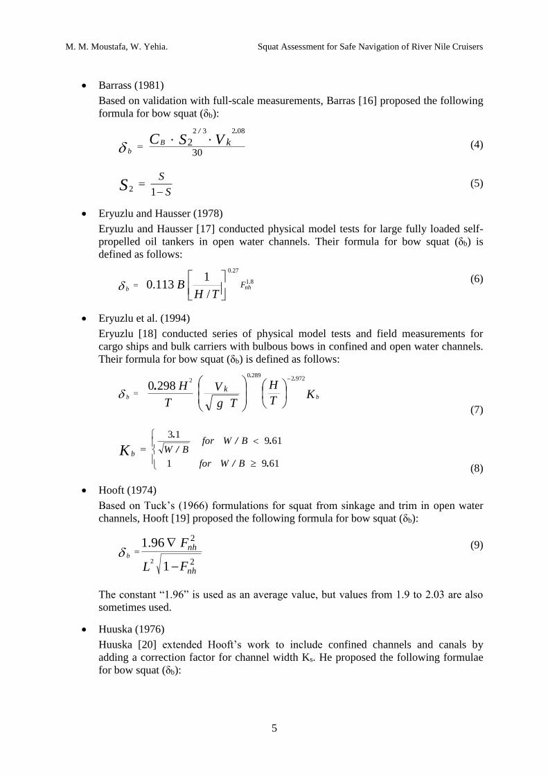
Barrass (1981)
Based on validation with full-scale measurements, Barras [16] proposed the following
formula for bow squat (δb):
302
08232
VSC kB
b
./..
(4)
S
SS
12 (5)
Eryuzlu and Hausser (1978)
Eryuzlu and Hausser [17] conducted physical model tests for large fully loaded self-
propelled oil tankers in open water channels. Their formula for bow squat (δb) is
defined as follows:
8.1
27.0
/
1113.0 nhb
F
THB
(6)
Eryuzlu et al. (1994)
Eryuzlu [18] conducted series of physical model tests and field measurements for
cargo ships and bulk carriers with bulbous bows in confined and open water channels.
Their formula for bow squat (δb) is defined as follows:
KT
H
Tg
V
T
Hbb
k
97222890
2
2980.
.
.
(7)
6191
61913
./
.//
.
BWfor
BWforBWK b
(8)
Hooft (1974)
Based on Tuck’s (1966) formulations for squat from sinkage and trim in open water
channels, Hooft [19] proposed the following formula for bow squat (δb):
2
2
1
96.1
2
nh
nh
FL
Fb
(9)
The constant “1.96” is used as an average value, but values from 1.9 to 2.03 are also
sometimes used.
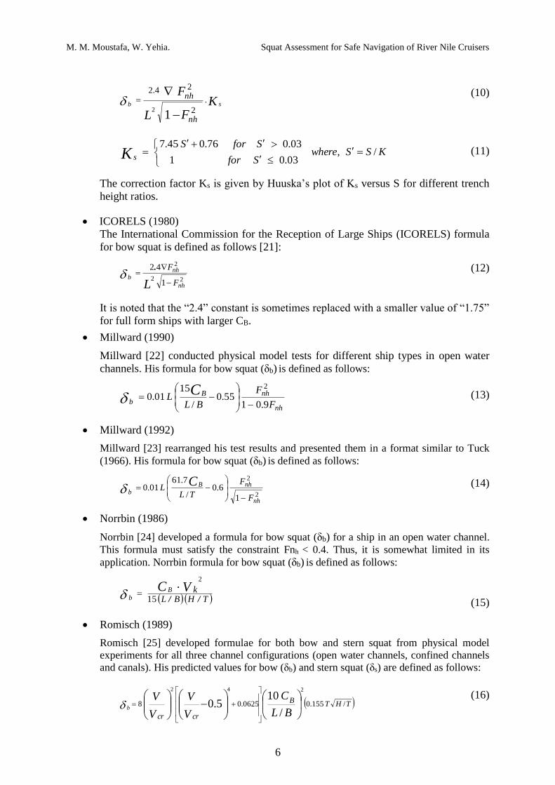
Huuska (1976)
Huuska [20] extended Hooft’s work to include confined channels and canals by
adding a correction factor for channel width Ks. He proposed the following formulae
for bow squat (δb):
M. M. Moustafa, W. Yehia. Squat Assessment for Safe Navigation of River Nile Cruisers
6
KFL
Fsb
nh
nh.
2
24.2
12
(10)
KSSwhereSfor
SforSK s
/,03.01
03.076.045.7
(11)
The correction factor Ks is given by Huuska’s plot of Ks versus S for different trench
height ratios.
ICORELS (1980)
The International Commission for the Reception of Large Ships (ICORELS) formula
for bow squat is defined as follows [21]:
22
2
1
42
nh
nhb
F
F
L
.
(12)
It is noted that the “2.4” constant is sometimes replaced with a smaller value of “1.75”
for full form ships with larger CB.
Millward (1990)
Millward [22] conducted physical model tests for different ship types in open water
channels. His formula for bow squat (δb) is defined as follows:
nh
nhBb F
F
BLL
C9.01
55.0/
1501.0
2
(13)
Millward (1992)
Millward [23] rearranged his test results and presented them in a format similar to Tuck
(1966). His formula for bow squat (δb) is defined as follows:
2
2
1
6.0/
7.6101.0
nh
nhBb
F
F
TLL
C
(14)
Norrbin (1986)
Norrbin [24] developed a formula for bow squat (δb) for a ship in an open water channel.
This formula must satisfy the constraint Fnh < 0.4. Thus, it is somewhat limited in its
application. Norrbin formula for bow squat (δb) is defined as follows:
THBLkVC B
b //
.
15
2
(15)
Romisch (1989)
Romisch [25] developed formulae for both bow and stern squat from physical model
experiments for all three channel configurations (open water channels, confined channels
and canals). His predicted values for bow (δb) and stern squat (δs) are defined as follows:
THTB
crcr BL
C
V
V
V
Vb
/155.00625.08
/
105.0
242
(16)
M. M. Moustafa, W. Yehia. Squat Assessment for Safe Navigation of River Nile Cruisers
7
THT
crcr V
V
V
VS
/155.00625.08 5.0
42
(17)
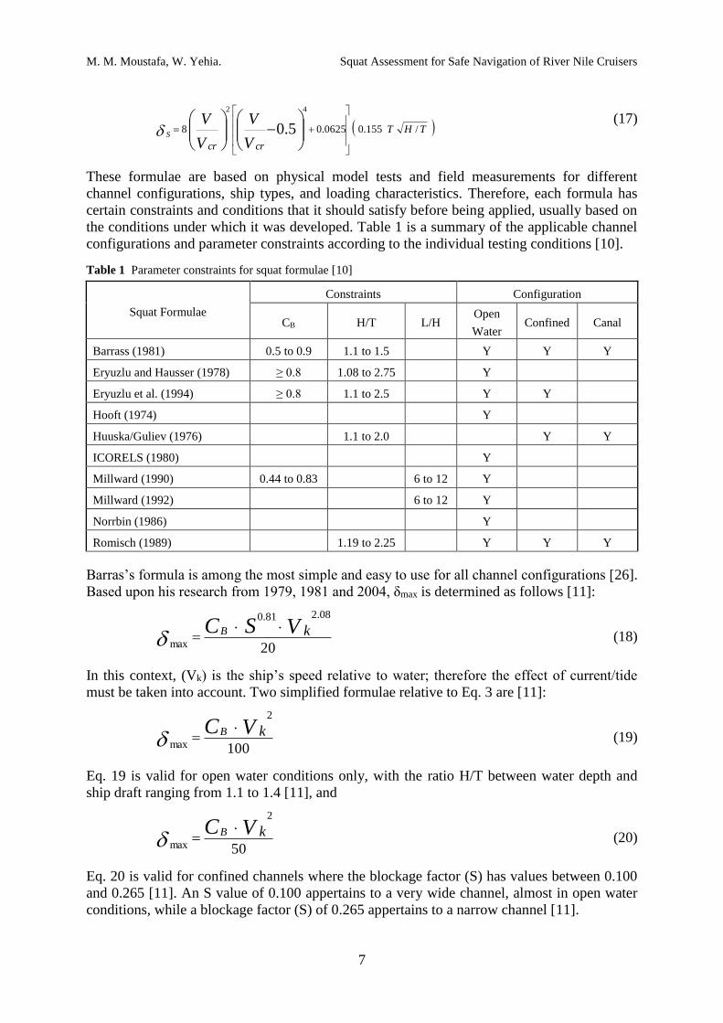
These formulae are based on physical model tests and field measurements for different
channel configurations, ship types, and loading characteristics. Therefore, each formula has
certain constraints and conditions that it should satisfy before being applied, usually based on
the conditions under which it was developed. Table 1 is a summary of the applicable channel
configurations and parameter constraints according to the individual testing conditions [10].
Table 1 Parameter constraints for squat formulae [10]
Squat Formulae
Constraints Configuration
CB H/T L/H Open
Water Confined Canal
Barrass (1981) 0.5 to 0.9 1.1 to 1.5 Y Y Y
Eryuzlu and Hausser (1978) ≥ 0.8 1.08 to 2.75 Y
Eryuzlu et al. (1994) ≥ 0.8 1.1 to 2.5 Y Y
Hooft (1974) Y
Huuska/Guliev (1976) 1.1 to 2.0 Y Y
ICORELS (1980) Y
Millward (1990) 0.44 to 0.83 6 to 12 Y
Millward (1992) 6 to 12 Y
Norrbin (1986) Y
Romisch (1989) 1.19 to 2.25 Y Y Y
Barras’s formula is among the most simple and easy to use for all channel configurations [26].
Based upon his research from 1979, 1981 and 2004, δmax is determined as follows [11]:
20
..08.281.0
max
VSC kB (18)
In this context, (Vk) is the ship’s speed relative to water; therefore the effect of current/tide
must be taken into account. Two simplified formulae relative to Eq. 3 are [11]:
100
.2
max
VC kB (19)
Eq. 19 is valid for open water conditions only, with the ratio H/T between water depth and
ship draft ranging from 1.1 to 1.4 [11], and
50
.2
max
VC kB (20)
Eq. 20 is valid for confined channels where the blockage factor (S) has values between 0.100
and 0.265 [11]. An S value of 0.100 appertains to a very wide channel, almost in open water
conditions, while a blockage factor (S) of 0.265 appertains to a narrow channel [11].
M. M. Moustafa, W. Yehia. Squat Assessment for Safe Navigation of River Nile Cruisers
8
7. Luxor-Aswan waterway
Luxor-Aswan waterway is 216 km long and mainly utilized by tourist Nile cruisers with
heavy traffic density of more than 5 units per hour [27], while the traffic density of other
navigation types can be neglected as it is limited to less than 2 units per hour [27]. Luxor-
Aswan waterway is classified as a first class waterway according to the classification of the
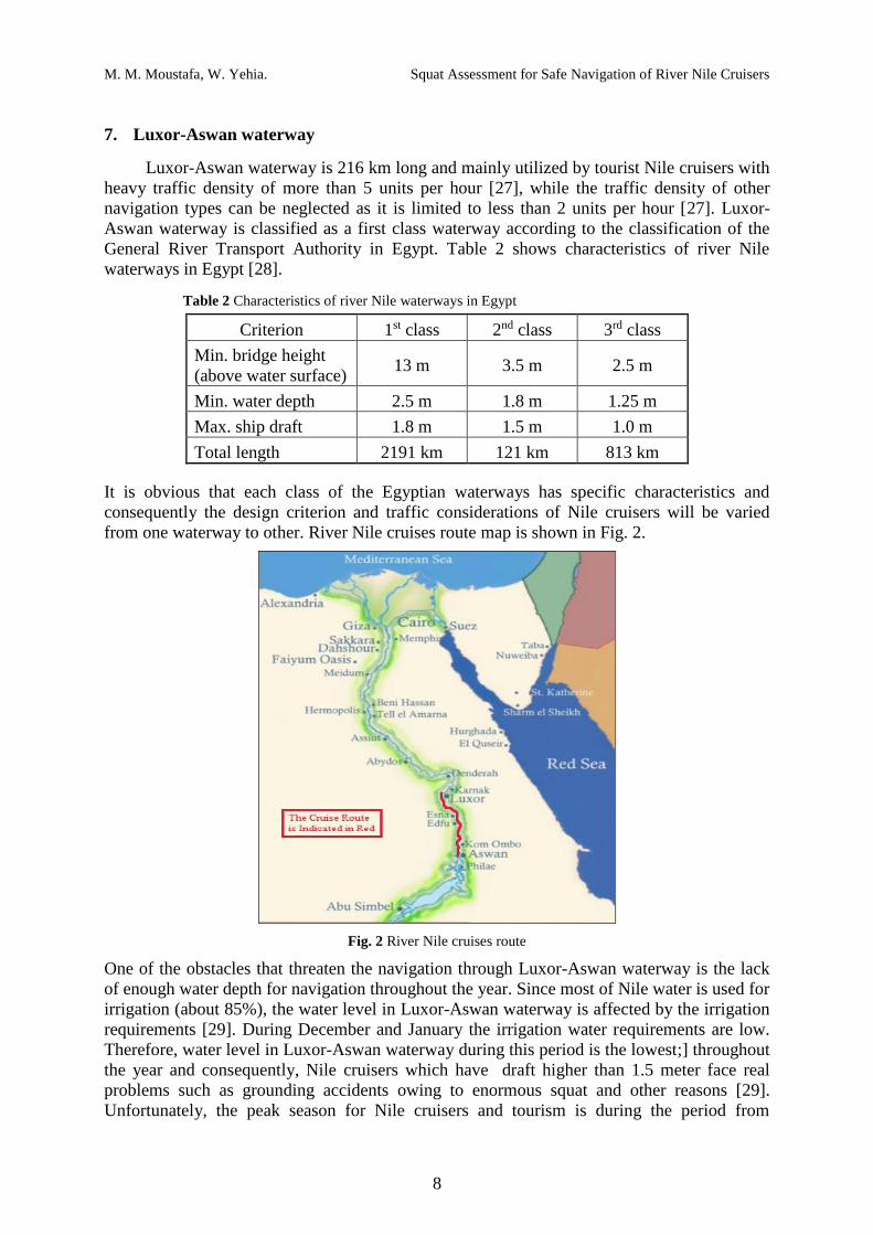
General River Transport Authority in Egypt. Table 2 shows characteristics of river Nile
waterways in Egypt [28].
Table 2 Characteristics of river Nile waterways in Egypt
Criterion 1st class 2nd class 3rd class
Min. bridge height
(above water surface) 13 m 3.5 m 2.5 m
Min. water depth 2.5 m 1.8 m 1.25 m
Max. ship draft 1.8 m 1.5 m 1.0 m
Total length 2191 km 121 km 813 km
It is obvious that each class of the Egyptian waterways has specific characteristics and
consequently the design criterion and traffic considerations of Nile cruisers will be varied
from one waterway to other. River Nile cruises route map is shown in Fig. 2.
Fig. 2 River Nile cruises route
One of the obstacles that threaten the navigation through Luxor-Aswan waterway is the lack
of enough water depth for navigation throughout the year. Since most of Nile water is used for
irrigation (about 85%), the water level in Luxor-Aswan waterway is affected by the irrigation
requirements [29]. During December and January the irrigation water requirements are low.
Therefore, water level in Luxor-Aswan waterway during this period is the lowest;] throughout
the year and consequently, Nile cruisers which have draft higher than 1.5 meter face real
problems such as grounding accidents owing to enormous squat and other reasons [29].
Unfortunately, the peak season for Nile cruisers and tourism is during the period from
M. M. Moustafa, W. Yehia. Squat Assessment for Safe Navigation of River Nile Cruisers
9
November to February. This period matches the low discharge period, which is considered a
real threat to the tourism industry.
8. Case study
In the following section, squat analysis is carried out for a specific Nile cruiser (“M/S
Davinci”) that runs from Luxor to Aswan. It carries approximately 136 guests and its
particulars are shown in Table 3. M/S Davinci has a block coefficient (CB) greater than 0.7,
hence maximum squat (δmax) will occur at bow.
Table 3 Main particulars of M/S Davinci (full load condition)
LOA 72.0 m T 1.75 m
LWL 70.5 m CB 0.83
B 13.6 m CWL 0.92
D 3.60 m Sun deck height 11.9 m
Up to now there is no exact evaluation method for ship squat. It is recommended to use a
reliable evaluation method which will deliver results on the so called “safe side”. Briggs [10]
presented a worked example to calculate ship squat of bulk carrier in open water channel
using the aforesaid squat formulae. The results of this study show that, Barras’s formula gives
the highest estimation of ship squat. Thus, in the present analysis squat analysis will be
carried out using Barras’s formula considering “safe side” concept.
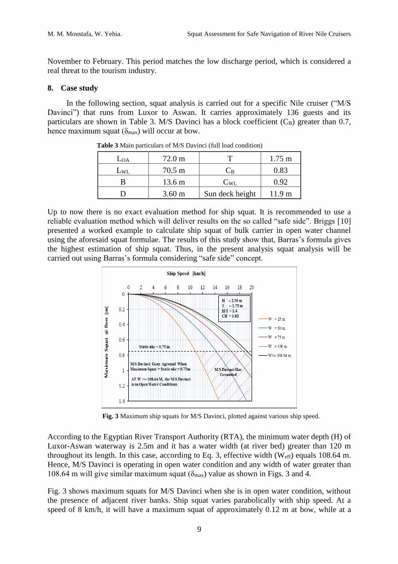
Fig. 3 Maximum ship squats for M/S Davinci, plotted against various ship speed.
According to the Egyptian River Transport Authority (RTA), the minimum water depth (H) of
Luxor-Aswan waterway is 2.5m and it has a water width (at river bed) greater than 120 m
throughout its length. In this case, according to Eq. 3, effective width (Weff) equals 108.64 m.
Hence, M/S Davinci is operating in open water condition and any width of water greater than
108.64 m will give similar maximum squat (δmax) value as shown in Figs. 3 and 4.
Fig. 3 shows maximum squats for M/S Davinci when she is in open water condition, without
the presence of adjacent river banks. Ship squat varies parabolically with ship speed. At a
speed of 8 km/h, it will have a maximum squat of approximately 0.12 m at bow, while at a
M. M. Moustafa, W. Yehia. Squat Assessment for Safe Navigation of River Nile Cruisers
10
speed of 16 km/h, it will have a maximum squat of around 0.51 m at bow. Fig. 3 shows that
maximum squat increases as river width decreases from 108.64 m down to 25 m.
When M/S Davinci has a forward speed of 10.85 km/h in river width of 25 m, it will have a
maximum squat of 0.75 m. grounding at bow will be occurred.
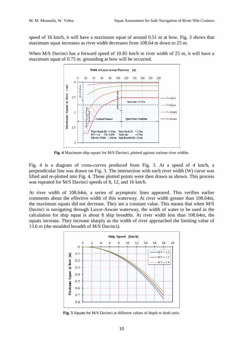
Fig. 4 Maximum ship squats for M/S Davinci, plotted against various river widths.
Fig. 4 is a diagram of cross-curves produced from Fig. 3. At a speed of 4 km/h, a
perpendicular line was drawn on Fig. 3. The intersection with each river width (W) curve was
lifted and re-plotted into Fig. 4. These plotted points were then drawn as shown. This process
was repeated for M/S Davinci speeds of 8, 12, and 16 km/h.
At river width of 108.64m, a series of asymptotic lines appeared. This verifies earlier
comments about the effective width of this waterway. At river width greater than 108.64m,
the maximum squats did not decrease. They are a constant value. This means that when M/S
Davinci is navigating through Luxor-Aswan waterway, the width of water to be used in the
calculation for ship squat is about 8 ship breadths. At river width less than 108.64m, the
squats increase. They increase sharply as the width of river approached the limiting value of
13.6 m (the moulded breadth of M/S Davinci).
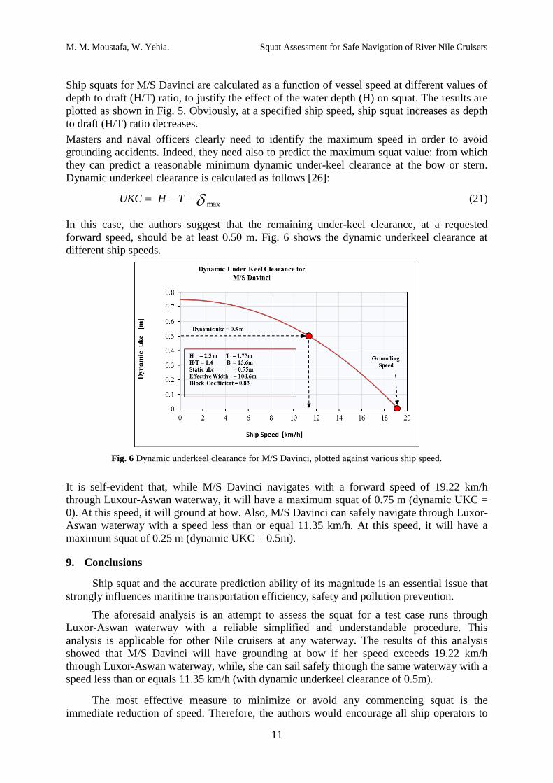
Fig. 5 Squats for M/S Davinci at different values of depth to draft ratio.
M. M. Moustafa, W. Yehia. Squat Assessment for Safe Navigation of River Nile Cruisers
11
Ship squats for M/S Davinci are calculated as a function of vessel speed at different values of
depth to draft (H/T) ratio, to justify the effect of the water depth (H) on squat. The results are
plotted as shown in Fig. 5. Obviously, at a specified ship speed, ship squat increases as depth
to draft (H/T) ratio decreases.
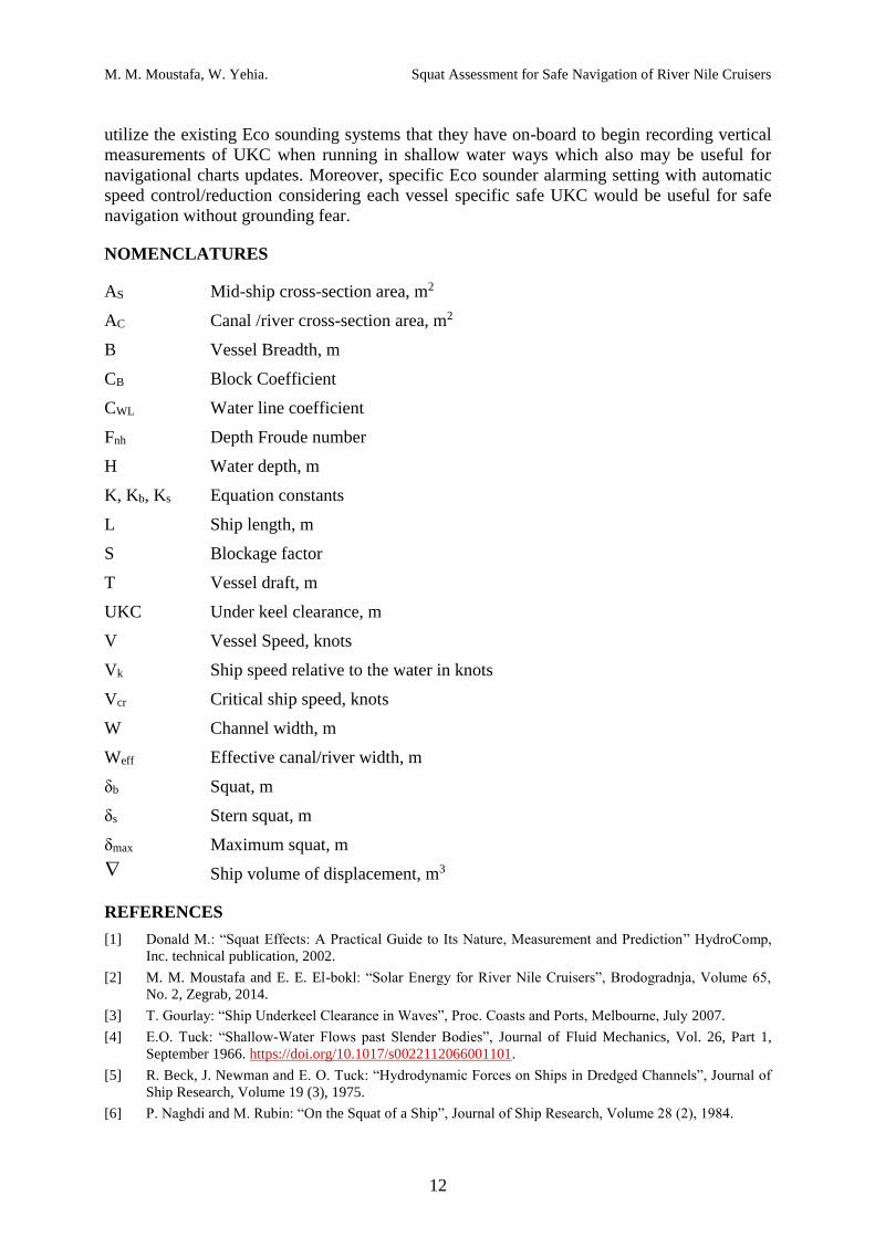
Masters and naval officers clearly need to identify the maximum speed in order to avoid
grounding accidents. Indeed, they need also to predict the maximum squat value: from which
they can predict a reasonable minimum dynamic under-keel clearance at the bow or stern.
Dynamic underkeel clearance is calculated as follows [26]:
max THUKC (21)
In this case, the authors suggest that the remaining under-keel clearance, at a requested
forward speed, should be at least 0.50 m. Fig. 6 shows the dynamic underkeel clearance at
different ship speeds.
Fig. 6 Dynamic underkeel clearance for M/S Davinci, plotted against various ship speed.
It is self-evident that, while M/S Davinci navigates with a forward speed of 19.22 km/h
through Luxour-Aswan waterway, it will have a maximum squat of 0.75 m (dynamic UKC =
0). At this speed, it will ground at bow. Also, M/S Davinci can safely navigate through Luxor-
Aswan waterway with a speed less than or equal 11.35 km/h. At this speed, it will have a
maximum squat of 0.25 m (dynamic UKC = 0.5m).
9. Conclusions
Ship squat and the accurate prediction ability of its magnitude is an essential issue that
strongly influences maritime transportation efficiency, safety and pollution prevention.
The aforesaid analysis is an attempt to assess the squat for a test case runs through
Luxor-Aswan waterway with a reliable simplified and understandable procedure. This
analysis is applicable for other Nile cruisers at any waterway. The results of this analysis
showed that M/S Davinci will have grounding at bow if her speed exceeds 19.22 km/h
through Luxor-Aswan waterway, while, she can sail safely through the same waterway with a
speed less than or equals 11.35 km/h (with dynamic underkeel clearance of 0.5m).
The most effective measure to minimize or avoid any commencing squat is the
immediate reduction of speed. Therefore, the authors would encourage all ship operators to
M. M. Moustafa, W. Yehia. Squat Assessment for Safe Navigation of River Nile Cruisers
12
utilize the existing Eco sounding systems that they have on-board to begin recording vertical
measurements of UKC when running in shallow water ways which also may be useful for
navigational charts updates. Moreover, specific Eco sounder alarming setting with automatic
speed control/reduction considering each vessel specific safe UKC would be useful for safe
navigation without grounding fear.
NOMENCLATURES
AS Mid-ship cross-section area, m2
AC Canal /river cross-section area, m2
B Vessel Breadth, m
CB Block Coefficient
CWL Water line coefficient
Fnh Depth Froude number
H Water depth, m
K, Kb, Ks Equation constants
L Ship length, m
S Blockage factor
T Vessel draft, m
UKC Under keel clearance, m
V Vessel Speed, knots
Vk Ship speed relative to the water in knots
Vcr Critical ship speed, knots
W Channel width, m
Weff Effective canal/river width, m
δb Squat, m
δs Stern squat, m
δmax Maximum squat, m
Ship volume of displacement, m3
REFERENCES
[1] Donald M.: “Squat Effects: A Practical Guide to Its Nature, Measurement and Prediction” HydroComp,
Inc. technical publication, 2002.
[2] M. M. Moustafa and E. E. El-bokl: “Solar Energy for River Nile Cruisers”, Brodogradnja, Volume 65,
No. 2, Zegrab, 2014.
[3] T. Gourlay: “Ship Underkeel Clearance in Waves”, Proc. Coasts and Ports, Melbourne, July 2007.
[4] E.O. Tuck: “Shallow-Water Flows past Slender Bodies”, Journal of Fluid Mechanics, Vol. 26, Part 1,
September 1966. https://doi.org/10.1017/s0022112066001101.
[5] R. Beck, J. Newman and E. O. Tuck: “Hydrodynamic Forces on Ships in Dredged Channels”, Journal of
Ship Research, Volume 19 (3), 1975.
[6] P. Naghdi and M. Rubin: “On the Squat of a Ship”, Journal of Ship Research, Volume 28 (2), 1984.
M. M. Moustafa, W. Yehia. Squat Assessment for Safe Navigation of River Nile Cruisers
13
[7] I.W. Dand and A. M. Ferguson: “Estimating the Bow and Stern Sinkage of a Ship under Way in Shallow
Water”, the Naval Architect, 1973.
[8] T. Gourlay: “The Effect of Squat on Steady Nonlinear Hydraulic Flow Past a Ship in a Channel”,
Schiffstechnik Bd. 46. Ship Technol. Res. 46, 1999.
[9] I.W. Dand: “On Full Form Ships in Shallow Water: Some Methods for the Prediction of Squat in
Subcritical Flows”, National Physical Laboratory, Ship Division, Ship Report 160, 1972.
[10] M. Briggs: “ Ship squat predictions for ship/tow simulator”, Coastal and Hydraulics Engineering
Technical Note - CHETN-I-72, U.S. Army Engineer Research and Development Center, Vicksburg,
2006.
[11] C. B. Barrass: “Ship Design and Performance for Masters and Mates”, Elsevier Butterworth-Heinemann,
London, 2004.
[12] C. B. Barrass: “The phenomenon of ship squat”, International Shipbuilding Progress, 26, 44-47, 1979.
[13] T. Gourlay: “Mathematical and Computational Techniques for Predicting the Squat of Ships”, The
University of Adelaide, Department of Applied Mathematics, PhD thesis, 2000.
[14] A. Olivieri, F. Pistani, A. Avanzini, F.Stern and R. Penna: “Towing Tank Experiments of Resistance,
Sinkage and Trim, Wake, and Free Surface Flow Around a Naval Combatant, SEAN 2340 Model”, Iowa
Institute of Hydraulic Research, Technical Report No. 421, Iowa, 2001.
[15] H. Zeraatgar, K. A. Vakilabadi and R. Yousefnejad: “Parametric Analysis of Ship Squat in Shallow
Water by Model Test”, Brodogradnja, Vol. 62, No.1, Zegrab, 2011.
[16] C. B. Barrass: “Ship squat – A reply”, The Naval Architect, November, 1981.
[17] N. E. Eryuzlu and R. Hausser: “Experimental Investigation into Some Aspects of Large Vessel
Navigation in Restricted Waterways”, Proceedings of the Symposium of Aspects of Navigability of
Constraint Waterways Including Harbor Entrances, Vol. 2, 1978.
[18] N. E. Eryuzlu, Y. L. Cao and F. D’Agnolo: “Underkeel Requirements for Large Vessels in Shallow
Waterways”, 28th International Navigation Congress, PIANC, Paper S11-2, Sevilla, 1994.
[19] J. P. Hooft: “The Behavior of a Ship in Head Waves at Restricted Water Depth”, International
Shipbuilding Progress 244(21), 1974.
[20] O. Huuska: “On the Evaluation of Underkeel Clearances in Finnish Waterways”, Report No. 9, Otaniemi:
University of Technology, Ship Hydrodynamics Laboratory, 1976.
[21] ICORELS (International Commission for the Reception of Large Ships), Report of Working Group IV,
PIANC Bulletin No. 35, Supplement, 1980.
[22] A. Millward: “A Preliminary Design Method for the Prediction of Squat in Shallow Water”, Marine
Technology 27(1), 1990.
[23] A. Millward: “A Comparison of the Theoretical and Empirical Prediction of Squat in Shallow Water”,
International Shipbuilding Progress 39(417), 1992.
[24] N. H. Norrbin: “Fairway Design with Respect to Ship Dynamics and Operational Requirements”, SSPA
Research Report No. 102, Gothenburg, Sweden: SSPA Maritime Consulting, 1986.
[25] K. Romisch: Empfehlungen zur Bemessung von Hafeneinfahrten. Wasserbauliche Mitteilungen der
Technischen Universitat Dresden, Heft 1, 1989.
[26] S. P. Șerban, C. Katona and V. N. Panaitescu: “The Analysis of Squat and Underkeel Clearance for
Different Ship Types in a Trapezoidal Cross Section Channel”, University Politehnica of Bucharest,
Scientific Bulletin, Series D, Vol. 77, No. 3, 2015.
[27] H. El-Sersawy and A.F. Ahmed: “Inland Waterways Design Criteria and Its Applications in Egypt”,
Ninth International Water Technology Conference, IWTC9 2005, Sharm El-Sheikh, Egypt, 2005.
[28] The River Transport Authority: “Inland Navigation Guide for River Nile”, Egypt, 2008.
[29] Y. Raslan and M. R. Abdelbary: “Economical and Environmental Aspects of Navigation Development in
the Nile”, Sixth International Water Technology Conference, IWTC 2001, Alexandria, Egypt, 2001.
Submitted: 05.05.2016
Accepted: 24.01.2017.
M. M. Moustafa, [email protected]
W. Yehia, [email protected]
Naval Architecture and Marine Engineering Department,
Faculty of Engineering, Port Said University, Egypt.