Embed Size (px)
Citation preview

TTC Meeting, Nov. 2012, JLab TTC Meeting, Nov. 2012, JLab
SPX Crab Cavity Development and
Testing Result
Haipeng Wang
For the team of Short Pulse X-ray project at APS
from the
ANL-JLab-SLAC-LBNL-(Tsinghua-PKU)
Collaboration

TTC Meeting, Nov. 2012, JLab
SPX Project Baseline and Upgrade Plan
1: A. Zholents, P.
Heimann, M. Zolotorev,
J. Byrd, NIM A524.
385, (1999)
X-ray pulse compression

TTC Meeting, Nov. 2012, JLab
SPX0 (R&D): beam test fully dressed 2-cavity Cryomodule in APS ring
Sector 5 Sector 7
SPX0 will only be operated during the non-users periods
Demonstrate SPX is transparent to storage ring operation with cavities
detuned.
Test and evaluate performance of deflecting cavities and RF components.
Test design concepts for cavity, cavity/cryomodule alignment, LOM/HOM
absorbers, damper design and cryogenics load
Demonstrate cavity voltage regulation and control to required SPX
tolerance.
Demonstrate cavity differential phase control to required SPX tolerance.
Demonstrate that fs-level synchronization ( BW: 0.1 Hz – 1 MHz) can be
achieved
Opportunity for users to have a first look at short x-ray pulse
Mitigate risks as much as possible before the construction phase
– Effect of warm cavity ( SPX0 will operate in batch fill
mode only @ 2K LHe)
– System shakedown ( LLRF, HLRF, control, alignment,
etc.)
– Beam loading and rf power management
Beam dynamics tests
– Effects on lifetime and injection efficiency ( nonlinear
dynamics)
– Orbit stability, beam behavior during cavity quench
– Effects on single bunch accumulation limit ( impedance)
Diagnostics tests

TTC Meeting, Nov. 2012, JLab
Early Prototypes and Design Optimizations in 2007-2008
Courtesy of P. Kneisel, C. Ciovati, L Turlington
Courtesy of R. Rimmer First CCA1 Cavity
Cavity shape optimization by
CST, HFSS ANSYS
Courtesy of J. Shi and
G. Waldschmidt,

TTC Meeting, Nov. 2012, JLab
Design Comparison with Other Projects’ Crab Cavities
SPX cavity is frequency scaled up (2.815GHz , 8th harmonics of
APS RF) of elliptical type from KEKB design. It requires high
dV/dt and using part of RF curvature by the APS beam dynamics,
much different from LHC-HL-CC compact designs.

TTC Meeting, Nov. 2012, JLab
Design Comparison with Other Projects’ Crab Cavities
Scale different designs to same frequency, but to compare beam apertures
due to the HOM damping and beam emittance conservation requirement

TTC Meeting, Nov. 2012, JLab
Two Types of Bare Crab Cavity Designs for Down Selection in 2011
Input
Coupler
LOM
Damper
HOM
Dampers
Baseline
(Mark-I)
Alternate
(Mark-II)

TTC Meeting, Nov. 2012, JLab 8
Longitudinal and Transverse Impedance*
l
s
P
VR
2
2
GHzMfRps
44.0*
Stability
Threshold
Monopole
Impedance
Monopole Stability
Threshold
2
0
2
2
0
rkP
V
R
l
rr
t
mMRt
/4.1
mMRt
/9.3
Horizontal dipole
Vertical dipole
Dipole Stability
Threshold
Vertical Dipole
Impedance
Stability
Threshold
Stability
Threshold
Horizontal Dipole
Impedance
Trapped HOM in 4-cavity
cryomodule
Omega3P simulation
IPAC 2012, WEPPC086
Courtesy of L. Xiao etc

TTC Meeting, Nov. 2012, JLab
W / M
Hz
Frequency (GHz)
10 0 10 -1 10 -2 10 -3 10 -4
Coupler
HOM
2 3 4 5 6 7 8 9 10
W / M
Hz
Frequency Frequency (GHz) 2 3 4 5 6 7 8 9 10
10 2 10 1 10 0 10 -1 10 -2 10 -3 10 -4 10 -5 10 -6
• Total LOM / HOM induced power is 1.8 kW for Mark-
II cavity. Power is distributed through each of the
waveguides.
• Design specifications for dampers: LOM = 2kW /
HOM = 0.3 kW
• Waveguide damper design is based on PEP-II (10kW)
and KEK (500W) operational dampers.
• LOM damper is challenging due to high-power (2kW),
high frequency, and relatively narrowband, spectrum at
2.4GHz.
LOM/HOM Induced Power
HOM / Coupler
power spectrum
Coupler:
161 W
HOM 2:
154 W
HOM 1:
165 W
LOM :
1.12 kW
Beampipe:
6.1 W
Power spectral density at cavity ports
LOM
power
spectrum
HOM induced
loss through
cavity ports

TTC Meeting, Nov. 2012, JLab
Baseline CC-B1 Cavity Fabrication in 2010
EDM cut Y Nb fine grain RRR>250 plate CNC machine two halves and EBW Survey on LOM WG pre-alignment
Finished Y waveguide group Finished two half groups before
final equator EBW CCB1 cavity with Nb blank offs

TTC Meeting, Nov. 2012, JLab
Fabrication of CC-A2 Cavity by CNC Machining
Cut fixture plate machined fixture base RRR>250 large grain Nb ingor EDM wire cut Nb template
Machine outside surface Machine inside surface with 30um unfinished Milling tool head for last inner finish Machine inner surface on the base
Finished first half with 4mm wall thickness Match to other Al model half Outside finish of first half EDM wire cut Nb template for Y WG

TTC Meeting, Nov. 2012, JLab TTC Meeting, Nov. 2012, JLab
Cavity Surface Inspection by Bore Scope on Dec 07, 2010
On iris weld
trench like feature
On iris wall to
LOM WG
Indium residual?

TTC Meeting, Nov. 2012, JLab TTC Meeting, Nov. 2012, JLab
Cavity Surface Inspection and Treatment after Grinding and Hand Polishing
original trench like feature area
original Indium
residual area
• Cavity was mechanically polished on the interior
• 80um BCP in the production cabinet
• Furnace treated at 600oC for 10 hours
• Final BCP on bench 5um
• HPR ~1hr on R&D system
• Dry overnight in portable clean room class 10 area
• Final assembly and evacuation in class 100 room
• RF test at Dewar#4, 23 Torr He level 110cm

TTC Meeting, Nov. 2012, JLab
Surface Treatment and Clean Room Assembly of Baseline CCB1 Cavity
• 90+10um BCP, ∆T <10°C
etching rate=1um/min to
allow iris and equator
removal the same amount
Inlet to outlet ∆T<1.5°C
• 600oC for 4hrs bake
• Ultrasonic degrease
• HPR in R&D system ~ 1hr
• Dried in class 10 for
several hrs
• Assembly in class 10
• Attached to test stand in
class 100
• First assembly got a leak
on pumping port after a few
days
the cavity got reassembled.
The indium seal on the
pumping flange got clean
with dry N2 blow and
plugging beam pipe.
• variable coupling was set
up
• <5e-10 mBar at 2K
• Liquid Helium Level in
128cm at the test start.

TTC Meeting, Nov. 2012, JLab
The Baseline Cavity CCB1was Qualified 3 Times at JLab/ANL
Test data: Feb. 11, 2011

TTC Meeting, Nov. 2012, JLab
The Baseline Cavity CCB1was Qualified 3 Times at JLab/ANL
TTC Meeting, Nov. 2012, JLab
Test Results for CC-A2 Cavity on August 13-16, 2011

TTC Meeting, Nov. 2012, JLab
CCA3 production cavities (3) EBW fabrication
Courtesy of B. Clemens and G. Slack

TTC Meeting, Nov. 2012, JLab
Port field on asymmetric meshing
Dipole field leaks from LOM WG to NbTi blank caused a low Q problem
TE20
dipole + monopole comp.
FTE10 cutoff<FLOM<FDFM<FTE20cutoff
2078MHz<2425<2815<4156MHz
TE10+TE20
Tuning to symmetry of dipole
field also corrects electric
center of the crabbing field
Qext=3e15
Courtesy of F. He and Y Yang
Beampipe stretching
Reduce LOM leak before flipping
4MHz/1.6mm/20dB

TTC Meeting, Nov. 2012, JLab
First Production Cavity Vertical Test and Lessons Learned
Courtesy of G. Wu, J. Holzbauer, Y. Yang

TTC Meeting, Nov. 2012, JLab
Mark-II type cavity first time passed QA spec after tuning the dipole field
Courtesy of G. Wu, J. Holzbauer, Y. Yang
LFD=-26.2Hz/(MV/m)2
AT 1.8K test, the average detected
temperature rising around 119mT is
140mK while in 89mT the average
rising is only 15mK.
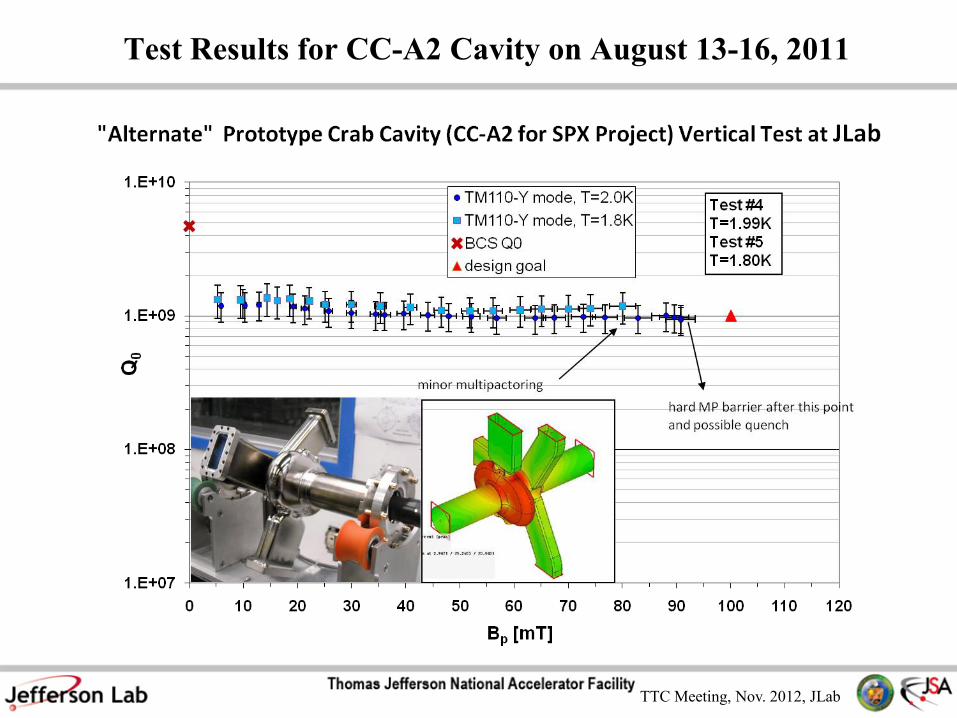
TTC Meeting, Nov. 2012, JLab
Double screws notch filter
on NC (SC?) waveguide
DPC shielding Q (with
top-hat) 4E11
LOM shielding Q (with
top-hat) 1.3E13
LOM shielding Q (port matched)
Qe-LOM * 1.1E6
CCA3-3 cavity with RF gaskets
will be VT tested at ATLAS this
week.
Design to block RF leaks from cavity to LOM WG and AlMg seals
Courtesy of F. He, G. Waldismidt and Y. Yang

TTC Meeting, Nov. 2012, JLab
Horizontal cavity test
• No LOM/HOM loads but
• with windows & WG bellows
• Fully dressed tuner
• 5kW amplifier
• 50W cooling@2K
• Analog and digital LLRF
• Ti helium vessel and bellows
is being welded at ORNL.
Courtesy of G. Wu, J.
Mammosser and B. Stillwell
Recent Progress toward horizontal test with tuner to be done in Nov.

TTC Meeting, Nov. 2012, JLab
Cryomodule Engineering Design (SPX0)
RF
Window
Nb neck
Vacuum
Vessel
2K
80K
300K
~7/8”
clearance
Coupler
Step
WR284
Bellows
2K
80
K
300K
RF
window
~7/8” clearance
WR340 Bellows Taper (60mm)
Tuner

TTC Meeting, Nov. 2012, JLab
Summary
• SPX(0) project has been successfully gone through critical
R&D phase. Crab cavity design, prototype, down selection,
vertical test result have demonstrated successfully the frontier
SRF technology application for both high gradient and high
current accelerator application.
• The recent test result shows a major milestone achievement
and to be ready for the CD2 review next month.
• Horizontal test will be the next milestone toward to the SPX0
cryomodule development.
• Engineering analysis and design are in good progress in all
technical details.
• SPX is a challenging, exciting and collaborating project for
producing short pulse x-rays for future science at APS.

TTC Meeting, Nov. 2012, JLab
Backup Slides

TTC Meeting, Nov. 2012, JLab
Why Was SRF Crab Cavity Design not Multi-cell?

TTC Meeting, Nov. 2012, JLab
TM110-y Same Pass-band Modes in a 5-cell APS Crab Cavity
Scaled Frequency Scaled External Q-factor Rt/Q
GHz for a flat 0-mode Hx field Ohm, at y=1cm offaxis distance
2.794523 1.69E+07 0.02
2.799700 2.96E+06 0.20
2.806271 9.21E+05 0.90
2.811808 5.29E+05 3.04
2.815488 8.07E+05 185.99
• One of multi-cell cavity design choices for APS crab
cryomodule.
• Are the same pass-band modes (SAMs) with given loaded
Qs and Rt/Qs allowed in the APS for a 200mA stable beam
operation with different filling patterns?
• If not, what their frequency spectrum and loaded Qs could
be allowed for a stable beam operation?
Hi Bob,
Sang-ho Kim from SNS ("HOM power in elliptical superconducting cavities for ...") referenced a
Cornell study that showed the standard deviation of the HOM frequencies to be sigma=0.00109
* |fn - fo|, where fn is HOM and fo is the tuned operating mode. If you take Haipeng's values
2.794523GHz and 2.815488GHz, respectively, this gives you sigma=22.85kHz. But how accurate
this is, and how applicable to dipole mode cavities, I don't know. On the other hand, I talked
with Louis again and the actual frequency control that is required is 135kHz (i.e., frev/2).]
Geoff
Robert Rimmer wrote:
Hi Geoff,
I presume that the SPM frequencies would tune very similarly to the operating mode so it might
be worth thinking about how they track. We would keep the operating mode very stable in
frequency with the active tuners, so the SPM's might stay put too? A bigger problem may be
that they might be different from one cavity to another because of manufacturing variations. In
other words controlling their absolute frequency might be harder than keeping them stable. On
the other hand their offset from the operating mode should be determined only by the cell to
cell coupling. I wonder how repeatable that might be?
Bob.
On May 18, 2010, at 7:03 PM, Geoff Waldschmidt wrote:
Hi Haipeng,
The Physics group looked at the multi-cell design and found that it would be difficult to
implement. From the impedance criteria that we've been using, it wouldn't work - which we
already know. But, in order to park it between dangerous sidebands, the SPM frequencies
would need to be controlled to within 50kHz which would appear to be very difficult. As far as I
can tell, it doesn't look possible. Do you have any further questions that I should ask?
Geoff
Subject: HOM too stong
Date: Tue, 18 May 2010 16:59:37 -0500
From: Louis Emery <[email protected]>
The limit on the Rt quantity that we use is 7.9 MOhm/m. This is specified in my OAG-TN-2007-
023, and other documents that Y. Chae wrote. Converting your (R/Q)' quantity to Rt gives me 47
MOhn/m, which is 6 times too large. I ran the instability code to see what growth rates the 47
MOhn/m HOM produces, and I got 6 times too high growth rate. I did this for 24 singlets. I
didn't do hybrid mode yet, but sine the Q's are so high, I think the results would be the same.
(For the normal conducting cavities of 3 years ago, a Q of 10000 would actually decay some
during one turn). I didn't do a randomization of frequencies, which "could" help. But in that
calculation I would have to include the other HOMs, and add three more cavities. If you think
you could reduce the Q by say 20, then I could try that with the full-blown calculation. It may be
marginal.
Louis Emery
APS: 7GeV, 100~300 mA

TTC Meeting, Nov. 2012, JLab
LOM/HOM RF-thermal Simulation on Waveguide SiC Dampers
LOM 2KW
HOM 500W
Loss of coolant
Total loss of power
τ=0 s
τ=1100 s
Courtesy of G. Waldschmidt and
B. Brajuskovic

TTC Meeting, Nov. 2012, JLab TTC Meeting, Nov. 2012, JLab
Frequency Recipe of CCA3 Cavity Design Based on CC-B1 CCA1-A2 Prototypes
Only available method for the
target frequency correction is
plastic tuning
Original frequency (MHz):
CC-A3-3: 2829.683
CC-A3-2: 2843.717
CC-A3-1 2831.070
CC-A3 Bare
cavity tuning
sensitivity:
~13MHz/mm
2809.830 on bench target

TTC Meeting, Nov. 2012, JLab
SPX Tuner Design Status:Tuner Resolution
12Gev Upgrade SPX SPXC100 Style Cavity
CC-A3
3.5mm wall
CC-A3
3.5mm wall
Tuning Sensitivity* Hz / um 310 8900 8900
Stiffness* N / um 1.2 23.0 23.0
Deflection required for 1
MHz frequency shiftum 3226 112 112
Force required for 1 MHz
frequency shiftN 3871 2584 2584
Stepper Motor Resolution Steps/rev 200 200 800Harmonic Drive Ratio 100 100 100
Ball Screw Pitch mm/rev 5 5 2
Resolution from Stepper**full step Hz / increment 13.6 390.4 39.0half step Hz / increment 6.8 195.2 19.5
quarter step Hz / increment 3.4 97.6 9.8
Resolution from PiezoPiezo resolution (drive axis) nm 0.13 0.33 0.33
Piezo resolution (cavity axis) Hz 0.01 0.52 0.52
* - SPX numbers taken from J. Liu FEA
** - Stepper controller enables up to 1/256 microstepping. As smaller steps are used there is a tradeoff of resolution for torque.
Testing is required to determine what level of micro-stepping is achievable.
Cavity Related Info
Tuner Related Info
Design Specifications
•Coarse Tuning Range:
400 kHz
•Tuning Resolution:
40Hz
TTC Meeting, Nov. 2012, JLab
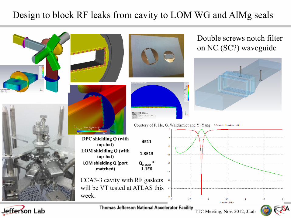
Particle Count vs. Temp: SiC +
Braze (Cusil / Incusil)
SiC temperature
cycling vs. time
LOM/HOM Loads Sample Tests and Production Fabrication
Courtesy of G. Waldschmidt and
B. Brajuskovic

TTC Meeting, Nov. 2012, JLab
• Qext ~ 1*106 which locates the
coupler step at 219 mm from
cavity center-line.
SPX cavity with
FPC waveguide and
single window
7 + 7
bellows
Coupler
step
Pillbox
window
Step
(mm)
Freq
(GHz)
Pfwd
(kW)
Qext
(No Round)
209 2.815 2.41 6.95E+05
219 2.815 1.82 9.14E+05
229 2.815 1.36 1.23E+06
HeliumV
essel
location
Forward power and Qext at
various step locations
(simulation results)
*Analytic values of forward
power vs. Qext
*Plot courtesy of T. Berenc
Input Power Coupler Design Opertimization

TTC Meeting, Nov. 2012, JLab
SPX0 Crab Cavities Alignment Requirement and Plan
30 um error each time fiducialization transferred
Wires stretching using TM110-y mode Courtesy of J. Mammoser and J. Feigold

TTC Meeting, Nov. 2012, JLab
HL-RF and LL-RF systems for SPX0: requirement and design layouts
Courtesy of Tim Berenc

TTC Meeting, Nov. 2012, JLab
LLRF System Bench Test for SPX0
Courtesy of Tim Berenc

TTC Meeting, Nov. 2012, JLab
Low Impedance Unshielded Bellows
Bellows Bunch
length [mm]
Nominal loss
factor Kloss
[mV/pC]
Shielding
APS 3 64 Yes
SOLEIL 3 20 Yes
SPEAR3 3 67 Yes
NSLS-II 3 18 Yes
American BOA
IV
3 455 No
American BOA
IV
10 1.517 No
Materials: Copper
plated Stainless
Steel or Phosphor
copper alloy
Courtesy of G. Wu

TTC Meeting, Nov. 2012, JLab
FPC Geometry Layout
Center line
125 mm at CM: 2K BC location
220.8 mm: Spool piece ends
147.5 mm: 1st bellow starts
7+7 bellows
180.2 mm: 11mm wide 80K location
249.6 mm: Pillbox Window
337.3 mm: Window flange
162.8 mm: Spool piece starts
Courtesy of G. Waldschmidt and J. Liu

TTC Meeting, Nov. 2012, JLab
FPC Thermal Analysis • Spool piece added to extend Nb waveguide – reduce heat load
due to cavity evanescent field.
• Bellows consists of a 7 + 7 convolution pattern with 80K
thermal strap.
• NbTi flange to Nb weld joint contact included.
3
9
RF Power
(W)
Loss
Tan
RF
Window
(W)
Cu
Plating
(um)
2K
(W)
3K
(W)
80K
(W)
300K
(W)
STATIC --- --- 10 -0.13 -1.01 -3.74 4.88
5.97
(Dynamic)0.007 103.4 10 -0.23 -1.38 -4.18 -103.55
Spool
piece
Input
Coupler
Step
80K 3K
2K
loss tan = 0.007
Pl = 103.4 W
Thermal analysis
with 0.5 MV
deflecting voltage
Courtesy of G. Waldschmidt and J. Liu

TTC Meeting, Nov. 2012, JLab
LOM Geometry Layout
Center line
125 mm at CM: 2K BC location
207.9 mm: Nb Wg ends
269 mm: 1st bellow starts
6+6 bellows
295.4 mm: 10mm wide 80K location
344.6 mm: Pillbox Window
453.7 mm: Window flange
Courtesy of G. Waldschmidt and J. Liu

TTC Meeting, Nov. 2012, JLab
LOM Double Window
• Double window separation was
optimized for ~2.2 – 2.4 GHz and are
relatively broadband from 2.2 – 4 GHz.
• LOM double window terminates in an
out-of-vacuum WR340 rf load.
• Prototype windows are currently being
tested at CML.
4
1
LOM double
window layout
Double window
return loss
LOM double
window
WR340 load
location
Courtesy of G. Waldschmidt and J. Liu

TTC Meeting, Nov. 2012, JLab
LOM Thermal Analysis
• Taper was extended into SS
cavity flange to improve
broadband rf performance.
• Convolutions were extended into
rf window flange to reduce 80K
heat load.
4
2
Input power
(kW)
Cu
Plating
(um)
Loss
Tan
Window
losses
(W)
RF Surf
losses
(W)
2K
(W)
80K
(W)
300K
(W)
STATIC 10 --- --- --- -1.36 -7.09 8.46
2 10 0.007 21.3 2.81 -1.57 -7.28 -15.30
Extended
taper
Thermal
profile
LOM
waveguide
geometry
Extended
convolutions
Thermal
analysis
Courtesy of G. Waldschmidt and J. Liu

TTC Meeting, Nov. 2012, JLab
Heat Flow Case 1 static Case 2 static Targeted
static
Expected
dynamic
Estimated
Total
2K (W) -1.2 -0.41811 < -1.0 < -1.3 <2.3
80K (W) 0.2 -0.73 < -5 < -5 <10
300K (W) 1.0 1.14 N/A N/A N/A
4
3
HOM Waveguide Static Heat Load*
*Courtesy of J. Liu
SS waveguide (3.18 mm
thick) - no copper plating
0.2mm
thick SS
bellows
Waveguide connects to
damper
Heat load estimation
per HOM waveguide
Case 1
Case 2
80K
300K
2K 2K
80K
300K

TTC Meeting, Nov. 2012, JLab 4
4
HOM Waveguide RF Performance*
*Design courtesy of J. Holzbauer
HOM
waveguide in
Cryomodule
Ridge: 2
x 4mm
Damper
location
Evanescence of
2815 MHz in
HOM waveguide
Power vs. Distance
from HV flange
(m)
Tuner
HOM
waveguide
HOM
waveguide RF
design
HOM
waveguide
return loss

TTC Meeting, Nov. 2012, JLab
HOM Dynamic Heat Load (Archive
Results)
4
5
Case
RF
Load
(W)
Nb
Neck
(mm)
Cu
Plating
(um)
2K
(W)
80K
(W)
300K
(W)
STATIC --- 15 10 -0.86 -0.37 1.23
Evanescent
(no traveling)2.03 15 10 -2.07 -1.09 1.12
80K
2K
300K
Results to be used only as an
estimation of dynamic loading Dynamic loading
– Cavity evanescent field at 0.5 MV deflecting volt
– 500W traveling wave at 2.8 GHz
Simplified geometry without ridge
Custom bellows will be not be included in the actual SPX geometry.
Traveling wave dynamic
losses contribute ~0.1 W to
2K
Thermal analysis
with 0.5 MV
deflecting voltage
Courtesy of G. Waldschmidt and J. Liu

TTC Meeting, Nov. 2012, JLab
Bellows: FPC / LOM
4
6
135.867 mm
WR340
154.812 mm
WR284
Location of FPC bellows convolutions was optimized for rf performance
LOM bellows utilizes taper in cavity flange for improved broadband performance
and cuts additional convolutions into the rf window flange to reduce 80K heat
load.
FPC LOM
Courtesy of G. Waldschmidt and J. Liu

TTC Meeting, Nov. 2012, JLab
Effect of Waveguide “Y” Group to LOM Leaking
Original Model M:/ANLcrab/JimHenry/cavity/CC-A3/CC-A3 cavity for Geoff
31jan12MOD10FEB.stp Meshing Tet10, 330k – 813k mesh cells
Frequency 2.829GHz
More descriptions Fully symmetric mesh: cavity mesh mirrored by X/Y/Z plane, LOM WG by X/Z
plane, Y-group by Y plane.
Conclusions Calculated Qe of TE10 in LOM WG is 9.4e6, and it is induced by monopole mode
excited by the reflection from Y-group.
Courtesy of F. He

TTC Meeting, Nov. 2012, JLab
How monopole mode be excited (1)
• Various modes in the beam pipe (circular WG) can be exited by
the cavity, including dipole of TE11, and Hexapole of TE31
• Below illustrate B field of cavity, TE11, and TE31
Courtesy of F. He

TTC Meeting, Nov. 2012, JLab
How monopole mode be excited (2)
• The TE31 in beam pipe excites TE10 in Y-group, and the
reflection excites TM01 in beam pipe, which in turn excites
monopole mode in cavity
• Below is B field of TE31, TM01 and monopole in cavity
Courtesy of F. He